Embed Size (px)
Citation preview

Performance Evaluation Test of the
Nemesis M3
September 2008
Prepared by
Institute for Defense Analyses 4850 Mark Center Drive
Alexandria, VA 22311-1882
for
Humanitarian Demining Program Night Vision and Electronic Sensors Directorate
Attn: AMSRD-CER-NV-CM-HD 10221 Burbeck Road
Fort Belvoir, VA 22060
Office of the Assistant Secretary of Defense Special Operations and Low-Intensity Conflict
Attn: OASD/SOLIC (RES) 2500 Defense Pentagon
Washington, DC 20301-2500

iii
PREFACE
In its continuing program to provide a complete size-range of area-preparation systems to the world’s humanitarian demining community, the United States Humanitarian Demining Research and Development Program, located at Ft. Belvoir, Virginia, developed a lightweight area-preparation system around the ASV Inc. SR-80 rubber-tracked crawler with a family of attachments. The system, assembled by Applied Research Associates, Inc., and named the Nemesis, is intended to cut and mulch up to Category 3 (difficult, up to 10 cm diameter trees) vegetation and to remove cutting debris. Attachments used during this evaluation test were the Bradco, Inc., Mini-Mag Mulcher Model XL 165-6; the Quick Attach Attachment, Inc., 4-in-1 bucket and Eagle Talon Grapple; and the Coneqtec, Inc., Universal AP1000 Cold Planer.
Testing of the Nemesis took place during the spring of 2008 at a central Virginia military test site. The government’s system and test engineer was Zeke Topolosky from the Humanitarian Demining Program staff; the system operator was Todd Sellmer. Test site support was provided by John Snellings and Arthur Limerick. Photography support was provided by Tanekwa Bournes of the Camber Corporation. Test data collection, test data analysis, and writing of this report were done by Harold Bertrand and Jennifer Soult of the Institute for Defense Analyses (IDA). Tom Milani (IDA) edited the report.

iv
TABLE OF CONTENTS 1 Purpose....................................................................................................................... 1
2 System Description.................................................................................................... 1
3 Test Site Description ................................................................................................. 5
3.1 Test Site A – Line-of-Site and Non-Line-of-Sight Testing ............................ 5
3.2 Test Site B – Vegetation Cutting...................................................................... 6
3.3 Test Site C – Planer Testing (Clay and Loam Mix) ....................................... 7
3.4 Test Site D – Planer Testing (Sandy Loam).................................................... 8
3.5 Test Site E – Grapple and 4-in-1 Testing........................................................ 9
4 Pre-Operation Maintenance Inspections ................................................................ 9
5 System Testing......................................................................................................... 11
5.1 Line-of-Site Control Distance ........................................................................ 11
5.2 GPS Testing ..................................................................................................... 11
5.3 Non-Line-of-Site Control Distance ................................................................ 12
5.4 Vegetation Cutting .......................................................................................... 13
5.5 Vegetation Removal and Site Clearing ......................................................... 15
5.6 Cold Planer Operations .................................................................................. 17
5.7 Cold Planer Operations After Modifications ............................................... 24
5.8 Track Blast Testing......................................................................................... 25
5.9 Antitank Mine Overpass Capability Test ..................................................... 27
6 Consumables............................................................................................................ 28
7 Maintenance and Maintainability ......................................................................... 29
8 Transportation ........................................................................................................ 30
9 Manpower and Training ........................................................................................ 30
10 Results of the Performance Evaluation Test ........................................................ 30

v
TABLE OF FIGURES
Figure 1: Nemesis with Vegetation Cutter Attachment...................................................... 1 Figure 2: Remote Operator Control Unit with Battery Box .............................................. 2 Figure 3: Remote Transmit/Receiver Antenna ................................................................... 2 Figure 4: Vehicle-Mounted Remote Transmit/Receive
Antennas and Electronics Box .................................................................................... 2 Figure 5: Vehicle-Mounted Pan/Tilt Camera ..................................................................... 2 Figure 6: Bradco Mini-Mag Mulcher XL 165-6................................................................. 3 Figure 7: Quick Combo, 4-in-1 Bucket .............................................................................. 4 Figure 8: Eagle Talon Grapple............................................................................................ 4 Figure 9: Cold Planer .......................................................................................................... 5 Figure 10: Test Site A, Line-of-Site Test Road .................................................................. 6 Figure 11: Test Site A, Non-Line-of-Site Test Road.......................................................... 6 Figure 12: Category 1, Easy................................................................................................ 7 Figure 13: Category 2, Moderate ........................................................................................ 7 Figure 14: Category 3, Difficult.......................................................................................... 7 Figure 15: Category 4, Very Difficult................................................................................. 7 Figure 16: Test Site C ......................................................................................................... 8 Figure 17: Test Site C, Mine Simulant and Witness Board Layout.................................... 8 Figure 18: Test Site D......................................................................................................... 9 Figure 19: Test Site D, Mine Simulant and Witness Board Layout ................................... 9 Figure 20: Test Site E ....................................................................................................... 10 Figure 21: Cab Raised for Maintenance Inspection.......................................................... 11 Figure 22: Line-of-Site Test Route ................................................................................... 12 Figure 23: Non Line-of-Site Test Route ........................................................................... 13 Figure 24: Vegetation/Dirt Mounds Created During Mulching Operations..................... 14 Figure 25: Category 1 Vegetation, Before Cutting.......................................................... 14 Figure 26: Category 1 Vegetation, After Cutting ............................................................. 14 Figure 27: Category 2 Vegetation, Before Cutting.......................................................... 14 Figure 28: Category 2 Vegetation, After Cutting ............................................................. 14 Figure 29: Category 3 Trees ............................................................................................. 15 Figure 30: Cutting Category 3 Trees ................................................................................ 15 Figure 31: Removing Large Tree with Branches.............................................................. 16 Figure 32: Removing Branches and Other Vegetation Debris ......................................... 16 Figure 33: Removing Large Tree...................................................................................... 16 Figure 34: Felling Large, Dead Tree................................................................................. 16 Figure 35: Remotely Controlling Nemesis with Operator Control Unit........................... 16 Figure 36: Scooping Small Debris with the 4-in-1 Bucket............................................... 17 Figure 37: Scooping Small Debris with the 4-in-1 Bucket............................................... 17 Figure 38: Grading with the 4-in-1 Bucket....................................................................... 17 Figure 39: Cold Planer Attached to Nemesis.................................................................... 18 Figure 40: Fiber Board Emplacement, Test Site C ........................................................... 18 Figure 41: Penetration Depth of Planer in Manual Operations......................................... 19 Figure 42: Dirt Buildup Inside Planer............................................................................... 19 Figure 43: Dirt Buildup in front of Planer ........................................................................ 19

vi
Figure 44: Test Site C, Vehicle Path................................................................................. 20 Figure 45: Box Mine Broken in Pieces by Planer, Test Site C
(Pieces Recovered by Test Personnel) ...................................................................... 21 Figure 46: Box Mine Untouched by Planer, Test Site C
(Uncovered by Personnel for Photo)......................................................................... 21 Figure 47: Board #1, Test Site C ...................................................................................... 21 Figure 48: Board #2, Test Site C ...................................................................................... 21 Figure 49: Board #3, Test Site C ...................................................................................... 21 Figure 50: Board #4, Test Site C ...................................................................................... 21 Figure 51: Test Site D, Vehicle Path ................................................................................ 21 Figure 52: Test Site D....................................................................................................... 22 Figure 53: Dirt and Vegetation Accumulation Inside Planer............................................ 22 Figure 54: Removal of Dirt and Vegetation Accumulation.............................................. 22 Figure 55: Witness Boards Test Site D............................................................................. 23 Figure 56: Angled Digging Tooth Plates in Planer........................................................... 24 Figure 57: Test 2 Configuration, Cover Removed,
Planer Disks Perpendicular to Shaft ......................................................................... 25 Figure 58: Board #1, Cold Planer Test 2 .......................................................................... 25 Figure 59: Board #2, Cold Planer Test 2 .......................................................................... 25 Figure 60: Board #3, Cold Planer Test 2 .......................................................................... 25 Figure 61: Board #4, Cold Planer Test 2 .......................................................................... 25 Figure 62: Mine A Blast ................................................................................................... 26 Figure 63: Vehicle after Mine A Blast.............................................................................. 26 Figure 64: Damage to Track Exterior, Mine A................................................................. 26 Figure 65: Damage to Track Interior, Mine A.................................................................. 26 Figure 66: Mine C Blast.................................................................................................... 27 Figure 67: Damage to Track Exterior, Mine C................................................................. 27 Figure 68: Damage to Outer Wheel, Mine C.................................................................... 27 Figure 69: Damage to Outer and Inner Wheel, Mine C.................................................... 27 Figure 70: Emplaced Smoke-Fused Antitank Mine......................................................... 28 Figure 71: Nemesis, Driving Over Smoke-Fused Antitank Mine .................................... 28 Figure 72: Pickup Truck Detonating Smoke-Fused Mine ................................................ 28

vii
TABLE OF TABLES
Table 1: Nemesis Specifications......................................................................................... 1 Table 2: Applied Research Associates, Inc., Modular Robotic Control System
Specifications.............................................................................................................. 3 Table 3: Bradco, Inc., Mini-Mag Mulcher XL 165-6 Specifications ................................. 3 Table 4: Quick Combo, 4-in-1 Bucket Specifications ........................................................ 4 Table 5: Eagle Talon Grapple Specifications ..................................................................... 4 Table 6: Coneqtec Universal AP1000 Cold Planer............................................................. 5 Table 7: Vegetation Categories........................................................................................... 7 Table 8: Vehicle Pre-Operation Maintenance Inspections ............................................... 10 Table 9: Surrogate Mine Data, Test Site C....................................................................... 20 Table 10: Fiber Board Data, Test Site C........................................................................... 20 Table 11: Surrogate Mine Data, Test Site D..................................................................... 23 Table 12: Fiber Board Data, Cold Planer Test #1, Test Site D......................................... 23 Table 13: Fiber Board Data, Cold Planer Test #2, Test Site D......................................... 25 Table 14: Mine Types and Emplacements, Track Blast Test ........................................... 26 Table 15: Suggested Items to be Added to Nemesis Tool Kit.......................................... 29 Table 16: Maintenance Schedule ...................................................................................... 29
1
1 Purpose
The purpose of this performance evaluation test was to determine if the Nemesis, an off-the-shelf, self-propelled area-preparation system, and its attachments can be operated under absolute control, at distances up to 400 m, through the use of a radio-controlled remote operating system. The performance evaluation included the remote deployment of the Nemesis, the cutting and clearing of varying vegetation categories, the use and control of a grapple and 4-in-1 bucket to clear an area where heavy vegetation cutting had occurred, and the use of an off-the-shelf pavement cold planer to potentially engage and destroy antipersonnel land mines buried to a depth of 15 cm (6 inches).
2 System Description
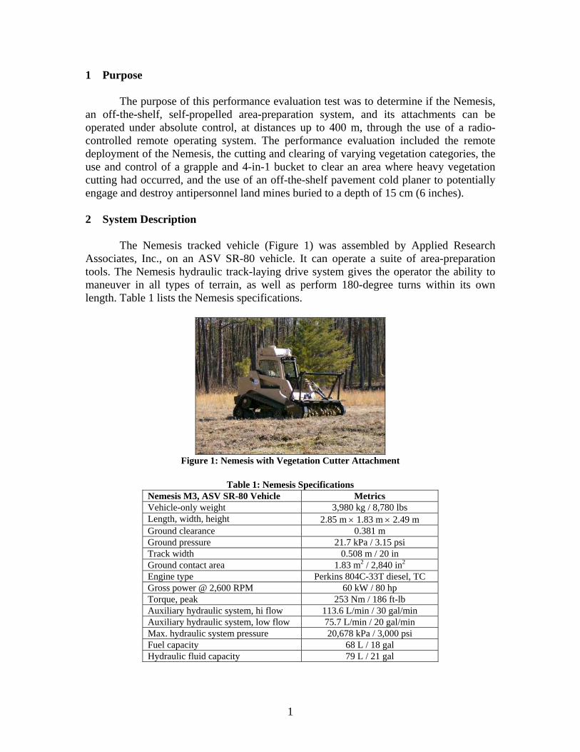
The Nemesis tracked vehicle (Figure 1) was assembled by Applied Research Associates, Inc., on an ASV SR-80 vehicle. It can operate a suite of area-preparation tools. The Nemesis hydraulic track-laying drive system gives the operator the ability to maneuver in all types of terrain, as well as perform 180-degree turns within its own length. Table 1 lists the Nemesis specifications.
Figure 1: Nemesis with Vegetation Cutter Attachment
Table 1: Nemesis Specifications
Nemesis M3, ASV SR-80 Vehicle Metrics Vehicle-only weight 3,980 kg / 8,780 lbs Length, width, height 2.85 m × 1.83 m × 2.49 m Ground clearance 0.381 m Ground pressure 21.7 kPa / 3.15 psi Track width 0.508 m / 20 in Ground contact area 1.83 m2 / 2,840 in2 Engine type Perkins 804C-33T diesel, TC Gross power @ 2,600 RPM 60 kW / 80 hp Torque, peak 253 Nm / 186 ft-lb Auxiliary hydraulic system, hi flow 113.6 L/min / 30 gal/min Auxiliary hydraulic system, low flow 75.7 L/min / 20 gal/min Max. hydraulic system pressure 20,678 kPa / 3,000 psi Fuel capacity 68 L / 18 gal Hydraulic fluid capacity 79 L / 21 gal

2
The Nemesis, which can also be controlled by an on-board operator, is fitted with the Modular Robotic Control System (MRCS), a remote-control system manufactured by Applied Research Associates, Inc. This system can provide up to 1.5 km line-of-sight control with video and up to 2.4 km without video. The remote system consists of a receiver antenna, a remote operator control unit, a battery, and the transmit antennas and cameras mounted on the Nemesis vehicle. The operator control unit gives remote operators the ability to fix vehicle speed, maneuver and perform operations with attachments, and view operations from a selection of four cameras (to include a pan/tilt camera that can be slewed by the operator to any desired forward-looking location) through the use of touch-screen and joystick controls (expandable up to eight cameras). In addition, the remote system is equipped with Global Positioning System (GPS) receiver to provide tracking, track mapping, and a record of the vehicle’s current location. Figures 2–5 give images of the remote system components, and Table 2 lists specifications of the radio control system.
Figure 2: Remote Operator Control Unit with Battery Box
Figure 3: Remote Transmit/Receiver Antenna
Figure 4: Vehicle-Mounted Remote Transmit/Receive Antennas and Electronics Box
Figure 5: Vehicle-Mounted Pan/Tilt Camera

3
Table 2: Applied Research Associates, Inc., Modular Robotic Control System Specifications Modular Control System Metrics Line-of-sight operating range (with video)
1.5 km
Weight 364 kg / 800 lbs Frequency 2.35–2.5 GHz Bandwidth 2.5 MHz
The set of attachments for Nemesis currently contains four skid-steer tools: a
mulcher, grapple bucket, 4-in-1 bucket, and a cold asphalt planer. The primary tool is the heavy-duty Bradco Mini-Mag Mulcher brush cutter, capable of cutting heavy undergrowth and trees up to 20 cm (8 inches) in diameter. Figure 6 shows the mulcher, with specifications given in Table 3.
Figure 6: Bradco Mini-Mag Mulcher XL 165-6
Table 3: Bradco, Inc., Mini-Mag Mulcher XL 165-6 Specifications
Mini-Mag Mulcher Metrics Overall width 213.3 cm / 84 in Cutting width 183 cm / 72 in Fixed hammers 54 Weight 1,045 kg / 2,300 lbs Hydraulic flow 113.5–127 L / 30–60 gal
The 4-in-1 bucket (the Quick Combo Bucket; see Figure 7) and the Eagle Talon
grapple (see Figure 8), both built by Quick Attach Attachments, Inc., are used to clear areas where vegetation has been cut or stockpiled. The 4-in-1 bucket can be used as a shovel or scoop to pick up and move debris or as a plow/light grapple to push debris into berms for later disposal. The grapple is ideal for lifting large, heavy items (rocks, logs, etc.) and moving them to nearby locations. Specifications for both attachments can be found in Tables 4 and 5.
4
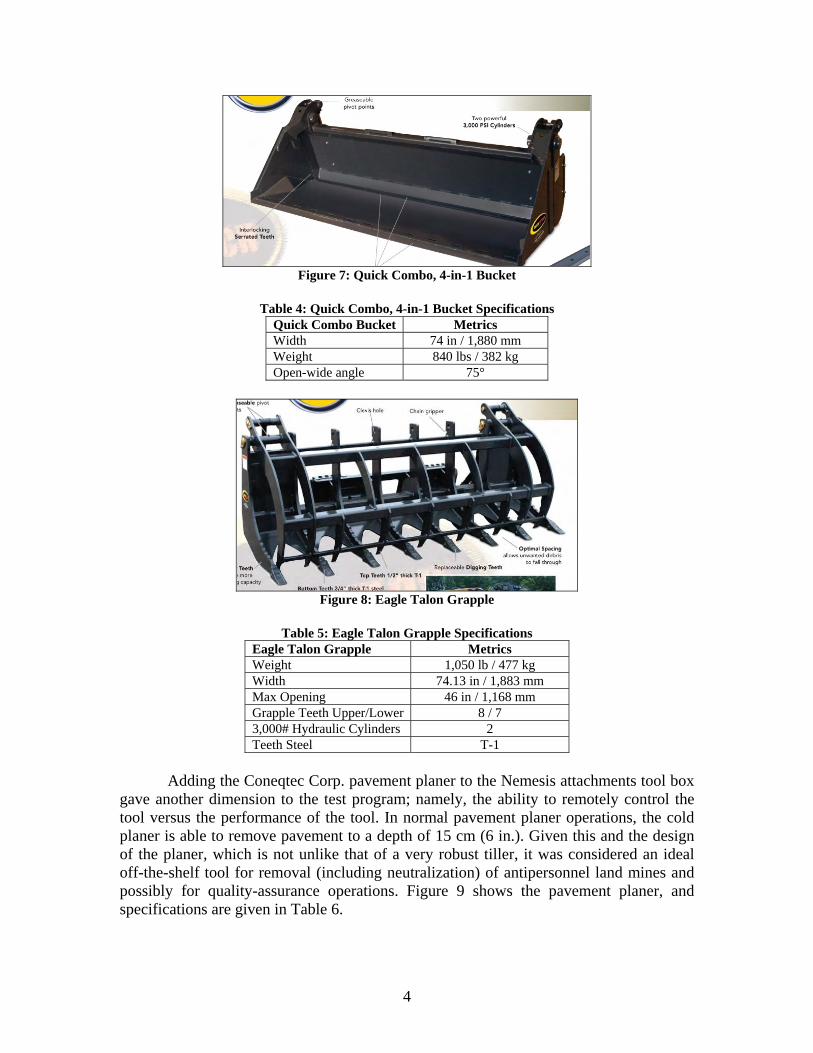
Figure 7: Quick Combo, 4-in-1 Bucket
Table 4: Quick Combo, 4-in-1 Bucket Specifications
Quick Combo Bucket Metrics Width 74 in / 1,880 mm Weight 840 lbs / 382 kg Open-wide angle 75°
Figure 8: Eagle Talon Grapple
Table 5: Eagle Talon Grapple Specifications
Eagle Talon Grapple Metrics Weight 1,050 lb / 477 kg Width 74.13 in / 1,883 mm Max Opening 46 in / 1,168 mm Grapple Teeth Upper/Lower 8 / 7 3,000# Hydraulic Cylinders 2 Teeth Steel T-1
Adding the Coneqtec Corp. pavement planer to the Nemesis attachments tool box
gave another dimension to the test program; namely, the ability to remotely control the tool versus the performance of the tool. In normal pavement planer operations, the cold planer is able to remove pavement to a depth of 15 cm (6 in.). Given this and the design of the planer, which is not unlike that of a very robust tiller, it was considered an ideal off-the-shelf tool for removal (including neutralization) of antipersonnel land mines and possibly for quality-assurance operations. Figure 9 shows the pavement planer, and specifications are given in Table 6.

5
Figure 9: Cold Planer
Table 6: Coneqtec Universal AP1000 Cold Planer
AP1000 Cold Planer Metrics Cutting width 101.6 cm / 40 in Cutting depth 15.24 cm / 6 in Shipping weight 1,225 kg / 2,700 lbs Tilt capability right or left 7.5°
3 Test Site Description
Five test areas were chosen to assess performance of the Nemesis and its attachments while under remote-control operation. Test Site A was used to measure the line-of-sight and non-light-of-sight remote-control ranges. Test Site B was used to evaluate the operational ability of the Mini-Mag Mulcher against various categories of vegetation, while it was operated remotely. Test Sites C and D were used to assess the performance of the remotely-operated cold planer. And a fifth test site, an area filled with fallen and cut trees and vegetation, was used to evaluate the performance of the grapple and 4-in-1 bucket. 3.1 Test Site A – Line-of-Site and Non-Line-of-Sight Testing
Test Site A contains well-maintained gravel roads that were used to determine operational distances achieved by the remotely operated Nemesis in clear, line-of-sight and obstructed, non-line-of-sight situations. For non-line-of-sight testing, obstructions included hills, trees, and other vegetation. Figures 10 and 11 show aerial images of the gravel roads (with the roads highlighted in yellow).

6
Point B
Point A
Figure 10: Test Site A, Line-of-Site Test Road
Stop
Start
Figure 11: Test Site A, Non-Line-of-Site Test Road
3.2 Test Site B – Vegetation Cutting
Test Site B is an area comprising Category 1 – Category 4 vegetation. Figures 12–15 and Table 7 show example images and descriptions of vegetation categories, respectively.

7
Figure 12: Category 1, Easy
Figure 13: Category 2, Moderate
Figure 14: Category 3, Difficult
Figure 15: Category 4, Very Difficult
Table 7: Vegetation Categories Category 1
(Easy) Category 2 (Moderate)
Category 3 (Difficult)
Category 4 (Very Difficult)
Light vegetation with minimal saplings up to
3 cm diameter
Moderate vegetation with sparse brush and saplings up to 6 cm
diameter
Moderate vegetation with brush, saplings and
trees up to 10 cm diameter
Heavy vegetation with dense brush, saplings and trees greater than
10 cm diameter Fairly level terrain with
minimal ruts Level to light rolling terrain with some ruts
Rolling terrain with lots of ruts
Steep hills with lots of ruts, very rugged terrain
Minimal debris and obstacles
Some debris and obstacles
Moderate debris and obstacles
Heavy debris and obstacles
3.3 Test Site C – Planer Testing (Clay and Loam Mix)
Figure 16 shows Test Site C, an area of little to no vegetation consisting of a clay and loam mix soil. Due to rain in the weeks prior to testing, the ground was relatively soft. Because this area was designated for planer testing, six antipersonnel mine simulants were buried at various depths, together with four 8 ft (length) × 1 ft (width) fiber witness boards. Figure 17 is a plan view of the layout. Use of the mines and boards during testing will be described in Section 5.6.

8
Figure 16: Test Site C
PMN
PMA-1 or Box mine
PMA-2
Buried flush
Buried 1” to top
Buried 3” to top
Buried 5” to top
Buried 4” to top
Buried 2” to top
Witness Boards
Figure 17: Test Site C, Mine Simulant and Witness Board Layout, Plan View
3.4 Test Site D – Planer Testing (Sandy Loam)
Test Site D was used for additional testing of the cold planer. The soil in Test Site D is a sandy loam consisting of a low, thick, grass-like vegetation with a heavy root system (see Figure 18). Like Test Site C, mine simulants and fiber boards were buried within the test area for the cold planer testing. Figure 19 is a plan view of the mine and board layout.

9
Figure 18: Test Site D
PMA-2
T72 AP
PMN
Buried 6” to top
Buried 6” to top
Buried 6” to top
Witness Boards
Figure 19: Test Site D, Mine Simulant and Witness Board Layout, Plan View
3.5 Test Site E – Grapple and 4-in-1 Testing
Test Site E was used to demonstrate the ability of the grapple and 4-in-1 bucket to clear an area of fallen trees and cut vegetation. Figure 20 shows the area chosen for Test Site E, which consisted of many large trees, as well as piles of cut vegetation. 4 Pre-Operation Maintenance Inspections
Before testing, the Nemesis and its remote-control system underwent an extensive pre-operation maintenance inspection. Inspection lists and schedules can be found in the Nemesis Operation Manual. Table 8 lists the maintenance and checks performed before the test.

10
Figure 20: Test Site E
Table 8: Vehicle Pre-Operation Maintenance Inspections
Maintenance Item Service Performed Grease fittings Lubricate Fluid levels Check and adjust levels as necessary Fan belt tension Check and adjust tension as necessary Fan belt condition Inspect and replace if worn or damaged Water separator Drain Track condition Inspect and replace if severely damaged Track tension Inspect and adjust as necessary Air cleaners Inspect and replace if damaged or heavily soiled Radiator/oil cooler Inspect and clean Undercarriages Inspect and clean Engine compartment Inspect and clean Drive socket rollers Inspect and replace if damaged or worn Loose nuts and bolts Inspect and tighten as required Lights Check Hoses and fittings Inspect Linkage and cables Check Battery Check voltage and inspect connections Lift arm safety stop Check Power quick attach Verify that quick attach is in locked position and adjust
as necessary High/low flow auxiliary switches Verify that switches are in their neutral positions and
adjust as necessary Joysticks Verify that joysticks are in their neutral positions and
adjust as necessary
All maintenance and inspections, except those items requiring under-the-cab investigation, can be performed by a single trained person in less than 2 hours. For under-the-cab inspections, three persons are recommended to lift and lock the cab in its raised position (see Figure 21). Tools needed to perform maintenance inspections will be provided with the Nemesis.

11
Figure 21: Cab Raised for Maintenance Inspection
5 System Testing 5.1 Line-of-Site Control Distance
The emphasis of this performance evaluation test is to assess the ability of the operator to remotely control the operation of the Nemesis vehicle and attachments from a safe distance. A line-of-sight test was conducted to determine the distance between the operator and the Nemesis that could reliably be negotiated. Using the forward-looking camera mounted on the top front of the Nemesis cab, the remote operator was able to drive the Nemesis from Point A to Point B, shown in Figure 22. Note that the path in Figure 22, shown in magenta, is the actual GPS-mapped path the vehicle traversed during this test. The travel path of the vehicle for this test totaled a distance of approximately 0.95 km, a straight-line distance (from Point A to Point B) of approximately 0.87 km. The Nemesis was shut off by test personnel when it reached Point B because of people and other moving vehicles on the roadway outside the viewing angle of the Nemesis camera. For the purpose of establishing a documented minimum reliable remote-control distance, the roughly 1 kilometer distance was considered more than sufficient. 5.2 GPS Testing
During the line-of-site test, the Nemesis passed by three GPS monuments located within the test site compound. Since a mapping of the vehicle’s path and its current GPS locations are viewable on the operator control unit, the GPS monuments located within the test site were used to verify the accuracy of the system’s GPS (latitude-longitude in degrees, elevation in meters). For each monument within the test site, the operator stopped the vehicle next to the monument location and the corresponding GPS coordinates were compared. In each case, the GPS coordinates of the remote guidance unit were identical to those of the GPS monuments.

12
Point B
Point A
Figure 22: Line-of-Site Test Route
5.3 Non-Line-of-Site Control Distance
Area preparation operations can necessitate the movement of a clearance vehicle to visually obstructed (from the operator’s point of view) locations. For this reason, a non-line-of-site control distance test was conducted to determine how far the operator could be from the Nemesis when it was beyond his line of sight and still retain radio contract and control.
The test was conducted in an area with hills, trees, and other vegetation acting as line-of-sight obstructions. The remote operator maintained complete control of the Nemesis for a travel path of approximately 0.45 km, at which time the video feed began to skip and delay. The operator continued movement along the road until a total loss of video feed occurred. Although the video transmission ceased, the operator maintained control of the vehicle. (Nevertheless, in any situations in which the vehicle is beyond the operator’s line of sight, it is recommended that operations stop once video feedback is lost.) The total path traversed was approximately 0.55 km, a straight-line distance of approximately 0.25 km. Figure 23 shows the non-line-of-site path.

13
Stop
Start
Figure 23: Non-Line-of-Site Test Route
5.4 Vegetation Cutting
Remote vegetation-cutting operations were performed using the Mini-Mag Mulcher attached to the Nemesis front arms. The test began with Category 1 vegetation cutting in Test Site B. The Category 1 vegetation test area covered, on average, a 7-degree slope, with slopes reaching 12.8 degrees at one end of the test area. When cutting on a slope, it was observed that the cutter tended to cut into the soil since it was not able to remain perfectly parallel to the ground (see Figure 24). On a few occasions, the tilled dirt formed mounds that were high enough to slow the Nemesis’s forward movement. In one instance, the flat underbelly of the Nemesis plowed enough soft dirt and cut vegetation under the vehicle to lift the tracks off the ground and stop its motion. The vehicle had to be backed off the dirt and vegetation mound, and the mound had to be further mulched by the cutter to sufficiently level the ground for forward movement. These mounds, and the effects they had on vehicle travel, were not always visible with the onboard camera system. In those cases, the remote operator had to reposition himself to get a line-of-sight view of the Nemesis to determine what was slowing the vehicle.
In total, the Nemesis with the attached mulcher was able to cut a 454.3 m2 area in 21 minutes, a 1,298 m2/hour cutting rate for Category 1 vegetation. Figures 25 and 26 give before cutting and after cutting looks at the Category 1 test area.
The second cutting performance evaluation included the remote cutting of Category 2 vegetation in Test Site B. Slopes within the Category 2 test area averaged 14 degrees, and cutting operations in this area were executed in with-slope passes to avoid the mobility issues caused by the vegetation and dirt mounds in Category 1 testing. This with-slope pattern appeared to alleviate some of the problems experienced earlier. In total, 240.8 m2 of Category 2 vegetation were cut within 28 minutes, giving a cutting rate of 516 m2/hour. Figures 27 and 28 show the Category 2 test area before and after cutting operations.

14
Figure 24: Vegetation/Dirt Mounds Created During Mulching Operations
Figure 25: Category 1 Vegetation, Before Cutting
Figure 26: Category 1 Vegetation, After Cutting
Figure 27: Category 2 Vegetation, Before Cutting
Figure 28: Category 2 Vegetation, After Cutting
Continued passes over cut vegetation did not result in continued mulching of the
cutting debris. Much of the debris was pushed into the soil loosened by the initial cutting pass and then passed over by the mulcher and vehicle. Where the debris was thick, it was

15
frequently swept under the Nemesis by the mulcher. However, the debris was light enough, and in small enough pieces, to be removed manually before demining.
Last, a test of the vehicle’s ability to remotely cut a Category 3-sized (10 cm) tree was conducted. To cut any tree with the mulcher, the Nemesis must be able to push the tree slightly over using the mulcher’s front bar to allow its cutting heads to reach (and cut) the tree. In soft soil, cutting Category 3 trees can be difficult because the vehicle’s tracks may not have enough ground traction to force these trees to bend. This traction problem was occasionally observed during this test, but ultimately, the Nemesis and mulcher were able to cut and mulch the tree. Figure 29 shows the Category 3 trees, and Figure 30 shows the Nemesis cutting them.
Figure 29: Category 3 Trees
Figure 30: Cutting Category 3 Trees
5.5 Vegetation Removal and Site Clearing
The grapple and 4-in-1 bucket were tested in Test Site E to determine their performance when remotely operated for area preparation. The test area consisted of many large cut or fallen trees, as well as branches, roots, and other vegetation debris.
Testing began with the grapple. Clearance performed with the grapple included the removal of large trees, branches, and other debris, as well as the felling and removal of two large, dead trees. Remote operators remarked that the remote controls for the grapple were easy to use, but noted that smooth operating skills take time to develop (e.g., determining ground clearance and lift height necessary for transport). One of the major obstacles to successfully operating the grapple remotely is the inability to see the lifted objects in the camera’s field of view. Operators cannot determine safe travel routes when grabbed objects are larger than the camera’s field of view when the grapple is lifted, which obstructs the view of the forward-looking camera. Because of these issues,

16
remote operations were completed by allowing operators to physically watch the movements of the vehicle as opposed to using the limited camera views. Figures 31–35 are images of grapple operations.
Figure 31: Removing Large Tree with Branches Figure 32: Removing Branches and Other Vegetation Debris
Figure 33: Removing Large Tree
Figure 34: Felling Large, Dead Tree
Figure 35: Remotely Controlling Nemesis with Operator Control Unit

17
After the grapple completed the removal of medium- and large-sized vegetation debris, site-clearance operations continued with the use of the 4-in-1 bucket. The bucket was used to scoop up and remove smaller debris and grade the area after all removal operations had been completed. Figures 36–38 are images of the 4-in-1 bucket’s scooping and grading operations.
Figure 36: Scooping Small Debris with the 4-in-1 Bucket
Figure 37: Scooping Small Debris with the 4-in-1 Bucket
Figure 38: Grading with the 4-in-1 Bucket
5.6 Cold Planer Operations
The cold planer is a 101.6 cm wide off-the-shelf asphalt planer that has potential for the removal or neutralization of small antipersonnel mines. Because the cutting width of the planer is less than the width of the Nemesis, the planer’s attached position relative to the vehicle will be offset to the right to cover the path of the right track (see Figure 39). This will ensure that the planer will engage threats before that side’s track overpasses them. The exposed left track will always operate in an area already cleared of mines to maintain its safety.

18
Figure 39: Cold Planer Attached to Nemesis
The cold planer was tested in Test Site C and Test Site D. For both tests,
antipersonnel mine simulants were buried at various depths to assess the planer’s ability to remove and possibly neutralize small mine threats. In addition, at each site, four 8 ft × 1 ft fiber boards were buried on edge, flush to the surface, at a distance of 5 m apart, to determine the depth reached by the planer during normal operations (see Figure 40). (See Figures 17 and 19 for images of the surrogate mine and fiber board layout.)
Figure 40: Fiber Board Emplacement, Test Site C
Before remote operations, the planer was manually operated within Test Site C. The purpose of this manual operation was to determine the ground-to-planer height that should be maintained for planing operations. During this test, it was observed that the weight of the planer caused the vehicle to rock while operating, stop abruptly when attempting to brake, and tilt forward when the planer was lifted off the ground. Also, due to the skewed location of the planer in relation to the Nemesis, the vehicle tended to drift to the right when forward operations straight ahead were attempted. The planer was able to penetrate 6 inches into the ground (see Figure 41), although buildup inside and in front

19
of the planer caused the vehicle’s forward movement to slow or stop on many occasions. Figures 42 and 43 show dirt buildup inside and in front of the planer.
Figure 41: Penetration Depth of Planer in Manual Operations
Figure 42: Dirt Buildup Inside Planer Figure 43: Dirt Buildup in front of Planer
The first remote operation performance test of the Planer occurred at Test Site C. As described in Section 3.3, Test Site C consists of flat ground with clay and loam mixed soil and spotty amounts of low vegetation (e.g. ,grass, shallow roots). Simulated mines and 8 ft × 1 ft fiber witness boards were buried according to the layout in Figure 44. The dotted line represents the path forward by the Nemesis.

20
PMN
PMA-1 or Box mine
PMA-2
Buried flush
Buried 1” to top
Buried 3” to top
Buried 5” to top
Buried 4” to top
Buried 2” to top
PASS 1 PASS 2 Board 1
Board 2
Board 3
Board 4
Figure 44: Test Site C, Vehicle Path
As this test progressed, the operator was better able to control the depth of the
planer. (This was the first time the cold planer had been used on the Nemesis and operated by the operator on any piece of equipment.) By the time the system was tilling the soil to a constant depth of 15 cm (6 in), the backpressure of the soil buildup inside and in front of the planer became so great that the track on the Nemesis lost traction, and the vehicle came to a halt. To restore forward progress, the operator had to raise the planer, but in doing so, the planer missed board #3 and missed the surrogate mines buried at 4 in and 5 in. Table 9 shows the effect of the planer on the buried mine stimulants. The effects of the operator’s learning to control the depth of the planer and the raising of the planer necessitated by the buildup of dirt are reflected in the depths of cuts made in the witness boards (see Table 10). Note that the data in Table 10 correspond to Figure 44 in the following way: The top-most board in the layout is Board #1, the bottom-most board in the layout is Board #4. The “left-hand” side of the board is the left-hand side when looking at the layout drawing. Images corresponding to the data are shown in Figures 45–50.
Table 9: Surrogate Mine Data, Test Site C Simulated Mine Description Outcome PMN, buried flush to surface Planer flipped mine over, but mine remained intact Box mine, buried 1 in. to the top of the mine Mine broken into pieces by the planer PMA-2, buried 2 in. to the top of the mine Mine broken into pieces by the planer PMA-2, buried 3 in. to the top of the mine Mine broken into pieces by the planer Box mine, buried 4 in. to the top of the mine Mine untouched PMN, buried 5 in. to the top of the mine Mine untouched
Table 10: Fiber Board Data, Test Site C Fiber Board Description Outcome Board #1, Left-hand side 4.6 in / 11.7 cm depth cut by planer Board #2, Left-hand side 2 in / 5.0 cm depth cut by planer Board #3, Left-hand side 5.4 in / 13.7 cm depth cut by planer Board #4, Left-hand side 6 in / 15.2 cm depth cut by planer Board #4, Right-hand side 6 in / 15.2 cm depth cut by planer Board #3, Right-hand side Untouched by planer Board #2, Right-hand side Slightly chewed by planer, but not cut Board #1, Right-hand side 2.25 in. depth cut by planer
21
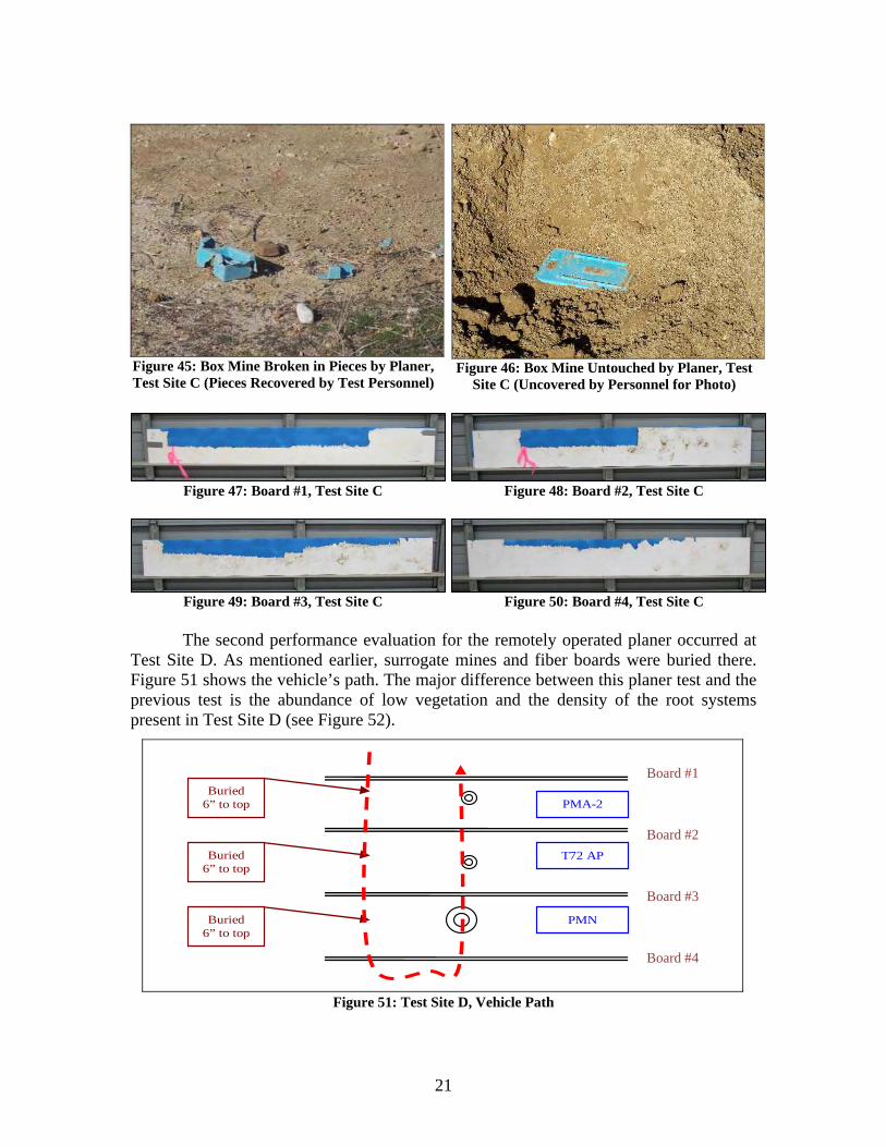
Figure 45: Box Mine Broken in Pieces by Planer, Test Site C (Pieces Recovered by Test Personnel)
Figure 46: Box Mine Untouched by Planer, Test Site C (Uncovered by Personnel for Photo)
Figure 47: Board #1, Test Site C Figure 48: Board #2, Test Site C
Figure 49: Board #3, Test Site C Figure 50: Board #4, Test Site C
The second performance evaluation for the remotely operated planer occurred at Test Site D. As mentioned earlier, surrogate mines and fiber boards were buried there. Figure 51 shows the vehicle’s path. The major difference between this planer test and the previous test is the abundance of low vegetation and the density of the root systems present in Test Site D (see Figure 52).
PMA-2
T72 AP
PMN
Buried 6” to top
Buried 6” to top
Buried 6” to top
Board #1
Board #2
Board #3
Board #4
Figure 51: Test Site D, Vehicle Path

22
Figure 52: Test Site D
The vegetation present in Test Site D posed new challenges for the planer.
Whereas in Test Site C the dirt accumulated within and in front of the planer, at Test Site D the density of the root systems and the moisture retained in the soil by the vegetation caused the dirt to pack in between the planer cutting tillers. Compounding this, the cutting tiller disks are canted to the mounting shaft to provide maximum coverage of the cutting teeth, but the variable separation between the tiller disks became traps for the roots and soil. This collection of dirt and roots was hard enough to require the use of picks and shovels for removal (see Figures 53 and 54).
Figure 53: Dirt and Vegetation Accumulation Inside Planer
Figure 54: Removal of Dirt and Vegetation Accumulation
As dirt and vegetation accumulated within the planer as it traveled forward, the
ground-penetration depth decreased dramatically. Furthermore, the inability of the planer to achieve deep penetration due to vegetation and dirt accumulation made contact with the buried surrogate mines impossible. As a result, all mines were left untouched by the planer. Tables 11 and 12 provide data on the buried mines and fiber boards for Test Site D. (Note that the top-most board in Figure 51 is labeled as Board #1 and the bottom-most board is Board #4.) A picture of the boards is shown in Figure 55. Black and red lines/arrows represent first and second pass, respectively.

23
Table 11: Surrogate Mine Data, Test Site D Surrogate Mine Description Outcome PMN, buried 6 in. to the top of the mine Untouched by the planer T72 AP, buried 6 in. to the top of the mine Untouched by the planer PMA-2, buried 6 in. to the top of the mine Untouched by the planer
Table 12: Fiber Board Data, Cold Planer Test #1, Test Site D Fiber Board Description Outcome Board #1 4.5 in. depth cut by planer Board #2 3.5 in. depth cut by planer Board #3 1.5 in. – 2.75 in. bowed cut by planer Board #4 1.75 in. depth cut by planer
Figure 55: Witness Boards Test Site D
Although the planer was clogged with soil at both test sites, it was slowed less
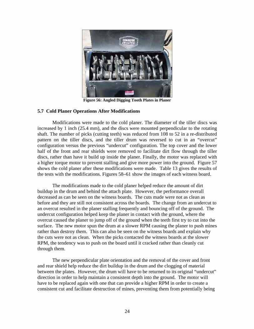
while remotely operated than while manually operated. The remote system allows the Nemesis to maintain a constant forward speed and a maximum speed limit. For example, in “slow-ops” mode, a forward speed down to 0.3 kph can be maintained. During this test, the optimum speed for the cold planer was 0.4 kph. In Test Site D, where more vegetation and root systems were present, the clogging problems limited the use of the planer. A manufacturer’s representative recommended that the cold planer be reengineered to incorporate straight-mounted tiller disks, as opposed to the canted disk installation (see Figure 56), to eliminate some of the dirt collection problems faced during operation. This dirt and vegetation accumulation not only slows operations, but could potentially present a danger to personnel clearing the dirt out of the tiller head if a mine became lodged inside the clogged dirt.
24
Figure 56: Angled Digging Tooth Plates in Planer
5.7 Cold Planer Operations After Modifications
Modifications were made to the cold planer. The diameter of the tiller discs was increased by 1 inch (25.4 mm), and the discs were mounted perpendicular to the rotating shaft. The number of picks (cutting teeth) was reduced from 108 to 52 in a re-distributed pattern on the tiller discs, and the tiller drum was reversed to cut in an “overcut” configuration versus the previous “undercut” configuration. The top cover and the lower half of the front and rear shields were removed to facilitate dirt flow through the tiller discs, rather than have it build up inside the planer. Finally, the motor was replaced with a higher torque motor to prevent stalling and give more power into the ground. Figure 57 shows the cold planer after these modifications were made. Table 13 gives the results of the tests with the modifications. Figures 58–61 show the images of each witness board. The modifications made to the cold planer helped reduce the amount of dirt buildup in the drum and behind the attach plate. However, the performance overall decreased as can be seen on the witness boards. The cuts made were not as clean as before and they are still not consistent across the boards. The change from an undercut to an overcut resulted in the planer stalling frequently and bouncing off of the ground. The undercut configuration helped keep the planer in contact with the ground, where the overcut caused the planer to jump off of the ground when the teeth first try to cut into the surface. The new motor spun the drum at a slower RPM causing the planer to push mines rather than destroy them. This can also be seen on the witness boards and explain why the cuts were not as clean. When the picks contacted the witness boards at the slower RPM, the tendency was to push on the board until it cracked rather than cleanly cut through them. The new perpendicular plate orientation and the removal of the cover and front and rear shield help reduce the dirt buildup in the drum and the clogging of material between the plates. However, the drum will have to be returned to its original “undercut” direction in order to help maintain a consistent depth into the ground. The motor will have to be replaced again with one that can provide a higher RPM in order to create a consistent cut and facilitate destruction of mines, preventing them from potentially being

25
pushed deeper into the ground. Further modifications will be made and tested at a later date. Results from further testing will be presented in a supplement to this report.
new pick placement with fewer picks
larger diameter plates
cover removed
bottom removed
new pick placement with fewer picks
larger diameter plates
cover removed
bottom removed
Figure 57: Test 2 Configuration, Cover Removed,
Planer Disks Perpendicular to Shaft
Table 13: Fiber Board Data, Cold Planer Test #2, Test Site D Fiber Board Description Outcome Board #1, left edge 4.6 in – 5 in depth cut by planer Board #1, right edge 4.5 in depth cut by planer Board #2, left edge 4.75 in – 4.9 in depth cut by planer Board #2, right edge 4.25 in – 6 in depth cut by planer Board #3, left edge 2.25 in – 2.75 in bowed cut by planer Board #3, right edge 5.4 in – 6.4 in depth cut by planer Board #4, left edge 5.75 in – 7 in depth cut by planer Board #4, right edge 5.5 in depth cut by planer
Figure 58: Board #1, Cold Planer Test 2 Figure 59: Board #2, Cold Planer Test 2
Figure 60: Board #3, Cold Planer Test 2 Figure 61: Board #4, Cold Planer Test 2 5.8 Track Blast Testing
The Nemesis rubber tracks were subject to blast testing using three antipersonnel mines. Each of the three mines was emplaced so that it would detonate in predetermined track locations. Table 14 gives the details.

26
Table 14: Mine Types and Emplacements, Track Blast Test
Mine Name TNT-Equivalent Explosive Content
Emplacement with Respect to Vehicle
A ~37 grams Rear end of right-side track B ~54 grams Rear end of right-side track C ~240 grams Front end of right-side track
The first mine to be used for testing was Mine A, a small, round antipersonnel
mine. Inspection of the vehicle after the blast showed damage to both the exterior and interior of the rubber track (see Figures 62–65). Exterior damage was limited to surface scarring, whereas interior damage resulted in a deep crack in one of the belt’s drive cogs. In addition to the track damage, the drive system encoder, which is located at the rear inside the loop of the track, sustained some damage. As a result of the damage, the vehicle veered slightly left during straight drives.
Figure 62: Mine A Blast
Figure 63: Vehicle after Mine A Blast
Figure 64: Damage to Track Exterior, Mine A Figure 65: Damage to Track Interior, Mine A
The second mine used for blast testing was Mine B, but when the vehicle was driven over the mine, no blast occurred. Test personnel noted that this lack of an explosion could have been the result of a faulty mine or the vehicle’s overpass

27
capabilities for this particular type of mine. Because it is uncertain why this mine did not explode, no conclusions with respect to Mine B are made at this time.
The last mine tested, Mine C, had the largest explosive (TNT) content of the three mines tested. The blast from this mine damaged both the exterior and interior of the rubber track, as well as two of the graphite composite wheels inside the track. Although the damage was more severe than the damage sustained from Mine A, the vehicle was still able to function and could safely move both forward and backward after the blast. In fact, the Nemesis traveled approximately 200 m from the blast test site to a maintenance garage. Figures 66–69 are images of the blast and damage incurred from Mine C.
Figure 66: Mine C Blast
Figure 67: Damage to Track Exterior, Mine C
Figure 68: Damage to Outer Wheel, Mine C
Figure 69: Damage to Outer and Inner Wheel, Mine C
5.9 Antitank Mine Overpass Capability Test
The Nemesis vehicle has a reported overpass capability against antitank mines. This claim was tested in an Overpass Capability Test using a smoke-fused, large U.S. antitank mine. This smoke fuse has the same pressure-plate sensitivity as an armed mine, but releases smoke to indicate detonation.

28
To perform the test, the smoke-fused antitank mine was buried flush to the ground’s surface, as shown in Figure 69. The Nemesis was remotely driven over the mine without activating the fuse (Figure 70). The Nemesis then backed over the mine, again without setting the mine off. The mine was lifted and reburied with the fuse at one inch above the ground. The Nemesis again drove over the mine without detonating the fuse. To ensure the fuse was functioning properly and that the Nemesis had indeed demonstrated an overpass capability, test personnel drove a pickup truck over the mine. This set off the smoke fuse (see Figure 71), thus verifying that the Nemesis has a potential antitank mine overpass capability.
Figure 70: Emplaced Smoke-Fused Antitank Mine
Figure 71: Nemesis, Driving Over Smoke-Fused Antitank Mine
Figure 72: Pickup Truck Detonating Smoke-Fused Mine
6 Consumables
Consumables for operation of the Nemesis and its attachments include diesel fuel (68 L) and hydraulic fluid (79 L). Refilling the tanks requires the use of a dispenser fitted with a nozzle because the refill ports are located under the rear hood of the cab.
During the test, 9.4 hours of operation were logged on the engine clock. During this time, the hydraulic fluid did not need refilling, and fuel consumption averaged 7.14
29
liters per hour. Also, the test averaged 5.7 hours of remote operation from a fully charged remote-system battery. 7 Maintenance and Maintainability
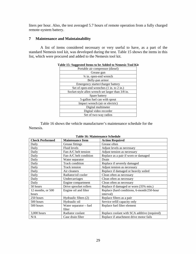
A list of items considered necessary or very useful to have, as a part of the standard Nemesis tool kit, was developed during the test. Table 15 shows the items in this list, which were procured and added to the Nemesis tool kit.
Table 15: Suggested Items to be Added to Nemesis Tool Kit Portable air compressor (diesel)
Grease gun ¾ in. open-end wrench
Belly-pan armor Emergency starter/charger battery
Set of open-end wrenches (1 in. to 2 in.) Socket-style allen wrench set larger than 3/8 in.
Spare battery 5-gallon fuel can with spout
Impact wrench (air or electric) Digital multimeter
Digital video recorder Set of two-way radios
Table 16 shows the vehicle manufacturer’s maintenance schedule for the
Nemesis.
Table 16: Maintenance Schedule Check Performed Maintenance Item Action Required Daily Grease fittings Grease often Daily Fluid levels Adjust levels as necessary Daily Fan-A/C belt tension Adjust tension as necessary Daily Fan-A/C belt condition Replace as a pair if worn or damaged Daily Water separator Drain Daily Track condition Replace if severely damaged Daily Track tension Adjust tension as necessary Daily Air cleaners Replace if damaged or heavily soiled Daily Radiator/oil cooler Clean often as necessary Daily Undercarriages Clean often as necessary Daily Engine compartment Clean often as necessary 50 hours Drive sprocket rollers Replace if damaged or worn (35% min.) 12 months, or 500 hours
Engine oil and filter Replace (hard conditions, 6-month/250-hour interval)
250 hours Hydraulic filters (2) Replace filters as a pair 500 hours Hydraulic oil Service refill capacity only 500 hours Water separator – fuel
filter Replace fuel filter element
3,000 hours Radiator coolant Replace coolant with SCA additive (required) N/A Case drain filter Replace if attachment drive motor fails
30
8 Transportation
Shipment of the Nemesis, its spares, and its attachments can be made in a 20 ft. ISO shipping container if the MRCS is removed from the roof of the vehicle. If MRCS equipment is left attached to the roof, the Nemesis and it attachments can be shipped on a flat rack. 9 Manpower and Training
Although the Nemesis can be operated by a single operator, it is recommended that a minimum of two operators be available for all operations. This is more critical during remote operation, where constant staring at the screen can be tiring. It is also recommended that the operators be trained to perform routine maintenance checks and repairs. Because of the weight of the cab, three people (two to lift, one to place the safety bar) are recommended for maintenance operations that require lifting the cab to an upright position.
Manual operation of the Nemesis requires little training if the operator has prior experience operating any skid-steer equipment. For remote operations, however, more training will be needed. Although the controls on the remote unit are straightforward and intuitive, operating both the vehicle and attachment simultaneously will take some practice to achieve smooth operations. This is particularly true when controlling both the Nemesis and the attachment with only the benefit of views from the on-board cameras. 10 Results of the Performance Evaluation Test
The ASV SR-80 vehicle is a powerful and agile tracked vehicle. There was no condition encountered during the test that the vehicle was not able to handle. Its power-to-weight ratio is adequate to maintain top vehicle-rated speed, even with a full bucket load of heavy debris. The lift height will allow use with any commercial hauling truck.
The Bradco, Inc., Mini-Mag Mulcher Model XL 165-6; the Quick Attach Attachment, Inc., 4-in-1 bucket; and Eagle Talon Grapple performed extremely well and were suitably matched with the ASV SR-80 vehicle. Although the front push bar on the mulcher prevented it from engaging some larger trees (when the trees would not bend enough to allow cutting teeth on mulcher to engage the tree), the push bar itself is needed to push away cut trees that might otherwise cause damage should they fall on the vehicle.
At this point, the results of the cold planer test are inconclusive. More testing is needed to arrive at the optimum manner in which to use the attachment. Also, since it is an in-ground working attachment, testing against live mines is needed.