Embed Size (px)
Citation preview
INTERNATIONAL JOURNAL OF MICROWAVE AND OPTICAL TECHNOLOGY,
Performance Evaluation of Radio over Fiber System Model in
Multipath Fading Channel at 60 GHz
Abstract—Providing high data rates and wide
bandwidth applications are the most important
challenges that mobile systems and radio networks
are trying to accomplish. Radio over Fiber (RoF)
system is a promoting research field since it
benefits of Passive Optical Network (PON)
advantages and unlicensed large bands in 60 GHz
millimeter band (57-64GHz). In this study, we
consider a complete downlink RoF system from
the central office to the end-user passing by the
base station and we study the impact of the
propagation environment on the whole system
performance and the radio coverage. Different
scenarios for multipath propagation are
considered (Line of Sight-LOS, Non Line of Sight-
NLOF). In particular, we have been interested in
Rayleigh and Rice propagation models for both
indoor and outdoor environments.
Optisystem/ADS Co-simulation has been
investigated to simulate RoF network coverage for
indoor and outdoor environments while
considering IEEE 802.15.3C application classes
and assuming 16-QAM, Q-PSK and B-PSK
modulation formats.
Index Terms- - RoF system, Rayleigh model, Rice
model, LoS, NLoS, indoor and outdoor
environments.
I. INTRODUCTION
Besides providing high data rates up to 10 Gbps, Radio over Fiber system is a promoting research domain that contributes to fiber based networks assessment and predicates optical network topology. The association of the millimeter band has led to RoF technology spread. Many standards releases for wireless transmission in 60 GHz band have been proposed. IEEE 802.15.3C standard dealing with physical layer (PHY) for wireless personal area network (WPAN) was released in October 2009 [1]. The standard offers four large bandwidth channels (2.16 GHz) that do not request licenses worldwide and provides three classes of modulation and coding schemes (MCSs) targeting different wireless connectivity
applications. Class 1 is deploying simple modulation schemas such as π /2 B-PSK and G-MSK while maintaining relatively high data rates up to 1.5 Gb/s. Class 2 was specified to achieve data rates up to 3 Gb/s using π/2 Q-PSK. Class 3 is deploying π/2 QAM and was specified to support high performance applications with data rates in excess of 5 Gb/s.
Besides providing high data rates up to 5 Gbps, the RoF centralized architecture is well suited for cognitive radio and global network management [2]. The centralized network architecture of RoF systems reduces the network cost, promotes the global network management and centralizes treatment of information. Therefore, when using RoF systems, it would be possible to allocate network resources dynamically. In recent decade, great efforts have been made to study different aspects of RoF systems operating at the millimeter bands. In fact, several researches have considered the channel design, mobility and handoff at 60 GHz [3].
In our recent work [4], we have considered a simple propagation model assuming LOS case to study RoF network coverage. Friis Equation defines the path loss during the signal propagation. This equation is used to estimate radio link range for free-space environment. We have assumed 16 dB/km losses due to atmospheric absorption at 60 GHz. In this paper, we study a more realistic propagation model assuming multi-path propagation and we investigate the impact of modulation format and data bit rates on RoF system performances. The main finding of this paper is to study the impact of propagation environment and application class on the RoF budget link, the system performance and the coverage range. We consider indoor and outdoor applications and different multipath propagation scenarios (LOS and NLOS) using Rayleigh and Rice propagation models.
VOL.9, NO.6, NOVEMBER 2014
460
IJMOT-2014-8-629 © 2014 IAMOT
Sarra Rebhi1*, Rim Barrak1, Mourad Menif1, Ali El Moussati2, 1 GRESCOM Laboratory, Higher School of Communications of Tunis, University of Carthage, Ariana, Tunisia
2 Signals, Systems and Information Processing team, National School of Applied Sciences, Oujda, Morocco E-mail:[email protected], [email protected], [email protected], [email protected]
INTERNATIONAL JOURNAL OF MICROWAVE AND OPTICAL TECHNOLOGY,
The paper is structured as follows. RoF system architecture is detailed in section II. Indoor and outdoor propagation models at 60 GHz and the budget link for different scenarios and different modulation formats are investigated in section III. Before concluding, simulation results for different indoor and outdoor environments are given.
II. ROF SYSTEM ARCHITECTURE
Micro-cells and pico-cells concepts are the innovative approach in mobile and heterogeneous network systems. Indeed, 4G networks (Release 12 LTE advanced) have considered these new aspects in order to boost system capacity and improve hotspots. Assuming medium range cell coverage for RoF systems at millimeter band due to high frequency and significant atmospheric absorption, we can move to pico-cells and micro-cells in indoor and outdoor environments respectively.
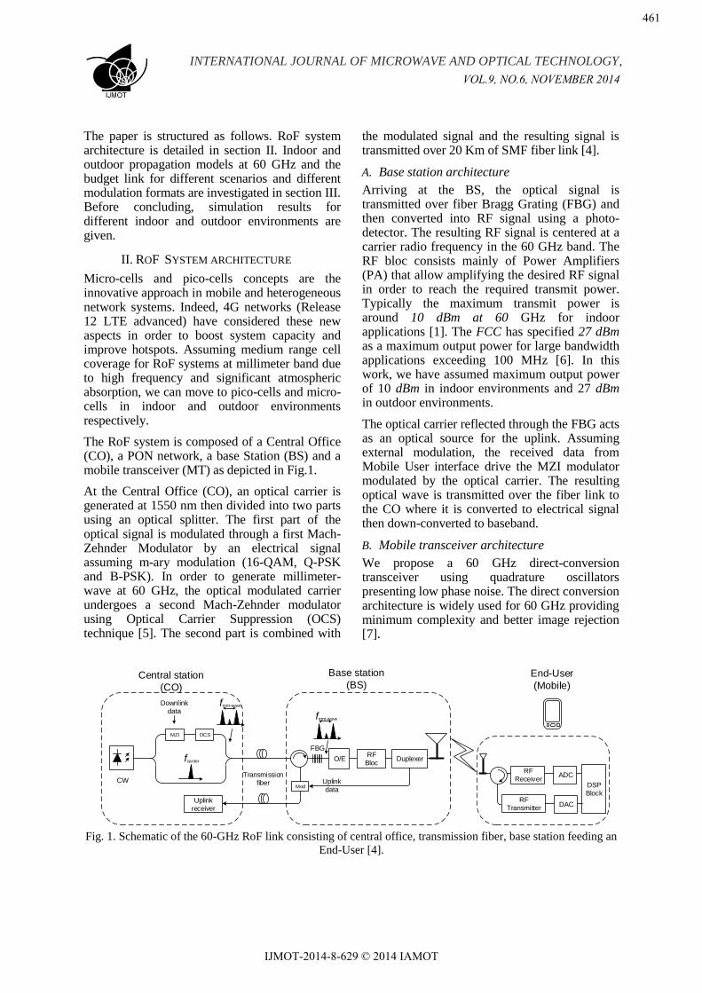
The RoF system is composed of a Central Office (CO), a PON network, a base Station (BS) and a mobile transceiver (MT) as depicted in Fig.1.
At the Central Office (CO), an optical carrier is generated at 1550 nm then divided into two parts using an optical splitter. The first part of the optical signal is modulated through a first Mach-Zehnder Modulator by an electrical signal assuming m-ary modulation (16-QAM, Q-PSK and B-PSK). In order to generate millimeter-wave at 60 GHz, the optical modulated carrier undergoes a second Mach-Zehnder modulator using Optical Carrier Suppression (OCS) technique [5]. The second part is combined with
the modulated signal and the resulting signal is transmitted over 20 Km of SMF fiber link [4].
A. Base station architecture
Arriving at the BS, the optical signal is transmitted over fiber Bragg Grating (FBG) and then converted into RF signal using a photo-detector. The resulting RF signal is centered at a carrier radio frequency in the 60 GHz band. The RF bloc consists mainly of Power Amplifiers (PA) that allow amplifying the desired RF signal in order to reach the required transmit power. Typically the maximum transmit power is around 10 dBm at 60 GHz for indoor applications [1]. The FCC has specified 27 dBm as a maximum output power for large bandwidth applications exceeding 100 MHz [6]. In this work, we have assumed maximum output power of 10 dBm in indoor environments and 27 dBm in outdoor environments.
The optical carrier reflected through the FBG acts as an optical source for the uplink. Assuming external modulation, the received data from Mobile User interface drive the MZI modulator modulated by the optical carrier. The resulting optical wave is transmitted over the fiber link to the CO where it is converted to electrical signal then down-converted to baseband.
B. Mobile transceiver architecture
We propose a 60 GHz direct-conversion transceiver using quadrature oscillators presenting low phase noise. The direct conversion architecture is widely used for 60 GHz providing minimum complexity and better image rejection [7].
CW
MZI OCS
Downlink data
Transmission fiber
Central station
(CO)
Base station
(BS)End-User
(Mobile)
ModUplink data
Uplink receiver
FBGRF
BlocO/E
fmm-wave
fmm-wave
fcarrier Duplexer
RF Receiver
DSP Block
ADC
RF Transmitter
DAC
Fig. 1. Schematic of the 60-GHz RoF link consisting of central office, transmission fiber, base station feeding an
End-User [4].
VOL.9, NO.6, NOVEMBER 2014
461
IJMOT-2014-8-629 © 2014 IAMOT
INTERNATIONAL JOURNAL OF MICROWAVE AND OPTICAL TECHNOLOGY,
PA
LNA
BPF
BPF
LO
0°
90°
0°
90°
LPF
LPF
LPF
PA
AGC
PAAntenna
DAC
ADC
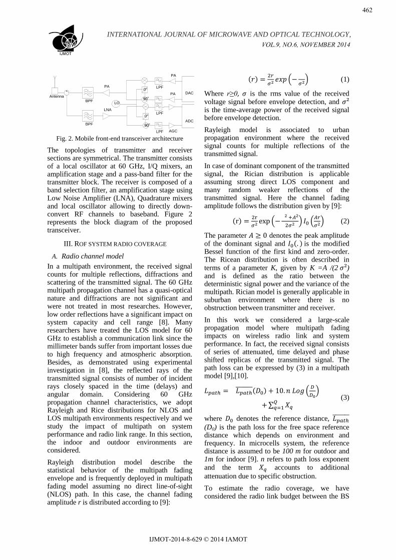
Fig. 2. Mobile front-end transceiver architecture
The topologies of transmitter and receiver sections are symmetrical. The transmitter consists of a local oscillator at 60 GHz, I/Q mixers, an amplification stage and a pass-band filter for the transmitter block. The receiver is composed of a band selection filter, an amplification stage using Low Noise Amplifier (LNA), Quadrature mixers and local oscillator allowing to directly down-convert RF channels to baseband. Figure 2 represents the block diagram of the proposed transceiver.
III. ROF SYSTEM RADIO COVERAGE
A. Radio channel model
In a multipath environment, the received signal counts for multiple reflections, diffractions and scattering of the transmitted signal. The 60 GHz multipath propagation channel has a quasi-optical nature and diffractions are not significant and were not treated in most researches. However, low order reflections have a significant impact on system capacity and cell range [8]. Many researchers have treated the LOS model for 60 GHz to establish a communication link since the millimeter bands suffer from important losses due to high frequency and atmospheric absorption. Besides, as demonstrated using experimental investigation in [8], the reflected rays of the transmitted signal consists of number of incident rays closely spaced in the time (delays) and angular domain. Considering 60 GHz propagation channel characteristics, we adopt Rayleigh and Rice distributions for NLOS and LOS multipath environments respectively and we study the impact of multipath on system performance and radio link range. In this section, the indoor and outdoor environments are considered.
Rayleigh distribution model describe the statistical behavior of the multipath fading envelope and is frequently deployed in multipath fading model assuming no direct line-of-sight (NLOS) path. In this case, the channel fading amplitude r is distributed according to [9]:
( )
(
) (1)
Where is the rms value of the received voltage signal before envelope detection, and is the time-average power of the received signal before envelope detection.
Rayleigh model is associated to urban propagation environment where the received signal counts for multiple reflections of the transmitted signal.
In case of dominant component of the transmitted signal, the Rician distribution is applicable assuming strong direct LOS component and many random weaker reflections of the transmitted signal. Here the channel fading amplitude follows the distribution given by [9]:
( )
(
) (
) (2)
The parameter denotes the peak amplitude of the dominant signal and ( ) is the modified Bessel function of the first kind and zero-order. The Ricean distribution is often described in terms of a parameter K, given by K =A /(2 ) and is defined as the ratio between the deterministic signal power and the variance of the multipath. Rician model is generally applicable in suburban environment where there is no obstruction between transmitter and receiver.
In this work we considered a large-scale propagation model where multipath fading impacts on wireless radio link and system performance. In fact, the received signal consists of series of attenuated, time delayed and phase shifted replicas of the transmitted signal. The path loss can be expressed by (3) in a multipath model [9],[10].
( ) (
)
∑
(3)
where denotes the reference distance,
(D0) is the path loss for the free space reference distance which depends on environment and frequency. In microcells system, the reference distance is assumed to be 100 m for outdoor and 1m for indoor [9]. n refers to path loss exponent and the term accounts to additional
attenuation due to specific obstruction.
To estimate the radio coverage, we have considered the radio link budget between the BS
VOL.9, NO.6, NOVEMBER 2014
462
IJMOT-2014-8-629 © 2014 IAMOT
INTERNATIONAL JOURNAL OF MICROWAVE AND OPTICAL TECHNOLOGY,
and the MT. The signal power at the input of the end-user receiver is given by friis equation:
(4)
where, PR and PT are the received and transmitted power, respectively. GR and GT are the gains of the terminal antennas, Lpath is the path loss given by (3).
The maximum radio coverage corresponds to a received power PR equal to the receiver sensitivity PRmin which is the minimum signal power producing an acceptable BER. It is given by:
(5)
where NF is the receiver noise figure in dB, SNRmin is the required signal to noise ratio in dB that meets the error rate criterion in term of BER and Pnoise is the input receiver noise power in dBm given by:
( ) ( ) (6)
with 10 log kT is the input noise power density and B is the channel bandwidth.
The minimum required signal to noise ratio SNRmin is given by:
( ⁄ ) ( ) (7)
where ⁄ is the bit energy to noise spectral density ratio in dB associated the required BER and D is the signal data rate.
Table 1 gives RoF system parameters that we considered for radio link budget.
Table 1: RoF system parameters
RoF system parameters Value
Modulation BPSK/QPSK/16 QAM
Bandwidth [1] 2.2 GHz
⁄ [11] 10.4/14.6
BER 10-6
BS output power Outdoor [6] 27 dBm
Indoor [1] 10dBm
MT Noise Figure figure 7 dB
BS antenna gain Outdoor 19 dB
Indoor 8 dB
MT antenna gain Outdoor
and indoor 17 dB
For the MT, the noise figure is assumed to be equal to 7 dB and the antenna is assumed to be directional with a gain of 17 dB [12]. For the BS
antenna, two cases are considered. The indoor BS antenna is assumed to be omnidirectional with a gain of 8 dB [13] and the outdoor BS antenna is assumed to be directional with a gain of 19 dB [14].
In the following sections, the indoor and outdoor radio coverage will be computed using equations (3)-(7).
B. Outdoor environment
In [4], we have proposed a radio link budget for a direct unobstructed LOS path between the transmitter and the mobile receiver and we have assumed free space environment. For a free space environment, the communication distance can reach 220 m assuming 16-QAM signal and 5.28 Gbps [1]. In this work we considered a more realistic channel model (3).
For outdoor environment, we assume 16 dB/Km oxygen absorption and 3.4 dB standard shadowing at 60 GHz as indicated by IEEE.802.11ad [10].
The path loss exponent n depends on environment specifications and varies between 2.7 and 3.5 for an outdoor suburban environment and it is more important (varying from 3 to 5) when obstructions are present [9].
For the outdoor LOS environment, the Rician fading model assumes the presence of a dominant multipath. This is the typical case of a rural environment. The radio link is about 154 m for 5.28 Gbps data rate and can reach 337 m deploying B-PSK modulation and assuming 1.65 Gbps.
For a NLOS model answering to Rayleigh distribution and in the absence of a dominant LOS, the received signal counts for low order reflections of the transmitted signal at 60 GHz. This is the typical case of an urban environment. The radio link distance varies between 225 m and 126 m deploying respectively 16-QAM and BPSK modulation when path loss exponent rises from 4 to 5.
In [15], we have computed radio link distance assuming 16 QAM modulation and maximum data rate of 5.28 Gbps. The communication distance D varies between 134 m to 126 m for NLOS model and between 154 m and 142 m for LOS scenario. We notice that when the required data rate increases, the maximum radio distance decreases and becomes close to the reference distance.
VOL.9, NO.6, NOVEMBER 2014
463
IJMOT-2014-8-629 © 2014 IAMOT
INTERNATIONAL JOURNAL OF MICROWAVE AND OPTICAL TECHNOLOGY,
Table 2 summarizes the radio link distance for different outdoor environments and different modulation formats and data rates.
Table 2: Calculated radio link distance for Rayleigh and Rice outdoor environments
Outdoor Path loss
exponent
Theoretical Radio distance
Class1
(B-PSK, 1.65 Gbps)
Class 2
(Q-PSK, 3.3 Gbps)
Class 3
(16-QAM, 5.28 Gbps)
Rice
(LOS)
2.7 337 m 261 m 154 m
3 299 m 237 m 147 m
3.3 271 m 219 m 142 m
Rayleigh
(NLOS)
4 225 m 191 m 134 m
4.5 208 m 178 m 130 m
5 193 m 168 m 126 m
C. Indoor environment
Due to high propagation losses in an indoor environment cell range is considerably reduced and is taken typically of the order of a few meters. Mm-waves indoor radio channels are more complex and subject to a severe multipath propagation phenomenon, but are of interest for many researchers [8-10].
Two models of channel propagation are proposed depending on environment and link frequency: statistical model and deterministic model. The Ray tracing model is the commonly used physical deterministic model at 60 GHz due to the optical geometric characteristic of the propagation channel and accurate results on millimetric band [8]. Many researchers have been investigated on a typical LOS scenario for 60 GHz WLAN considering a conference room for the LOS indoor environment using Tracing Ray models that requires a great knowledge on the propagation environment and allows obtaining precise as well as accurate predictions of signal propagation in the channel corresponding to the considered environment. The authors in [16-17] have approximated path loss exponent for different indoor scenarios and proposed 1.55 as path loss for LOS environment in indoor home and 1.77 for conference room. For indoor NLOS, path loss exponent can be taken as 3.85 for conference room and 2.44 for home environment. The author in [6] has proposed 1.2 and 1.65 in LOS scenario for an indoor environment.
Multipath fading is resulting from small-scale fading and large-scale fading. Fast fading can be defined as the fluctuation of the received signal in time and reflects system stability against small-
scale fading. The author in [18] mentioned that small average fade duration at 60 GHz leads to negligible fast fading impact for an indoor environment and noted that the millimeter band is robust to fast fading. However, large scale fading resulting from important path loss at 60 GHz and shadowing caused by constructive and destructive combination of multipath signal impact considerably on wireless radio link range. Considering most popular indoor environment parameters, we calculate wireless link range for LOS and NLOS scenarios. This is depicted in table 3. The resulted radio link distances point out that 60 GHz channel is more appropriate for LOS scenarios and pico-cells in case of indoor propagation, since radio link distance does not exceed 14 m for NLOS indoor environment.
We notice that high data rates applications form 3.3 Gbps to 5 Gbps are more suited for indoor environment since calculated radio distance concords with indoor environment proprieties, user concentration and applications requirements such HD video downloading .
Table 3: Calculated radio link distance for indoor environments
Indoor
environment
Path loss
exponent
Radio link distance
Class1 (1.65
Gbps)
Class 2 (3.3
Gbps)
Class 3 (5.28
Gbps)
Home LOS 1.55 61 m 40 m 18 m
NLOS 2.44 14 m 10 m 6 m
Conference
room
LOS 1.77 38 m 25 m 11m
NLOS 3.85 5 m 4.5 m 3 m
Corridor LOS 1.65 49 m 32 m 14 m
IV. SIMULATION RESULTS
Considering the complete downlink RoF system, we have simulated the wireless optic system using co-simulation between Optisystem software from Optiwave for the optic link and Agilent’s Advanced Design System for the radio link. To simulate RoF system performance, we have selected optical and 60 GHz components chosen from published scientific papers as detailed in [4].
In this section, we validate the theoretical distance range coverage for indoor and outdoor environment by simulating Optic/radio system Error Vector Magnitude (EVM) at the End User. In [15] we have simulated EVM considering 16 QAM modulation and 5.28 Gbps and we have demonstrated that simulated EVM for indoor radio cell are acceptable. In this paper, we simulate EVM for variable distance in both LOS
VOL.9, NO.6, NOVEMBER 2014
464
IJMOT-2014-8-629 © 2014 IAMOT
INTERNATIONAL JOURNAL OF MICROWAVE AND OPTICAL TECHNOLOGY,
and NLOS scenarios assuming Q-PSK and BPSK modulations.
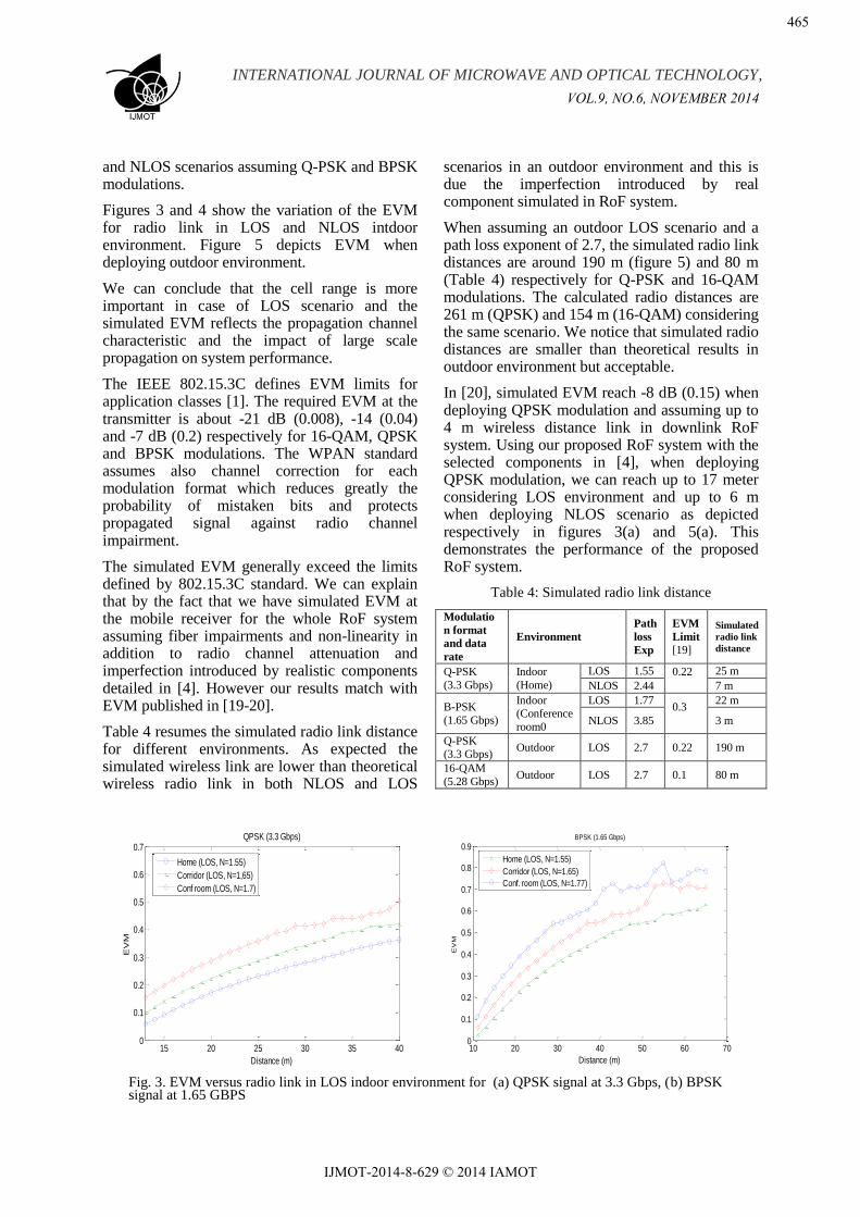
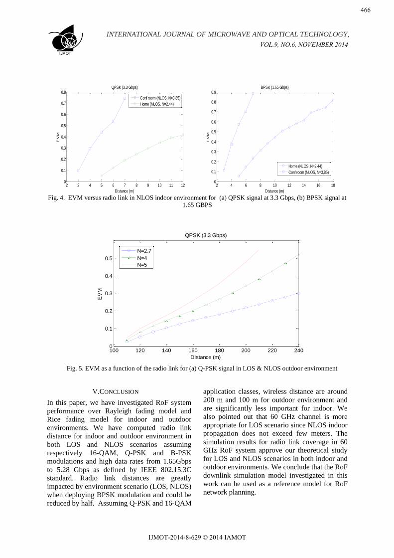
Figures 3 and 4 show the variation of the EVM for radio link in LOS and NLOS intdoor environment. Figure 5 depicts EVM when deploying outdoor environment.
We can conclude that the cell range is more important in case of LOS scenario and the simulated EVM reflects the propagation channel characteristic and the impact of large scale propagation on system performance.
The IEEE 802.15.3C defines EVM limits for application classes [1]. The required EVM at the transmitter is about -21 dB (0.008), -14 (0.04) and -7 dB (0.2) respectively for 16-QAM, QPSK and BPSK modulations. The WPAN standard assumes also channel correction for each modulation format which reduces greatly the probability of mistaken bits and protects propagated signal against radio channel impairment.
The simulated EVM generally exceed the limits defined by 802.15.3C standard. We can explain that by the fact that we have simulated EVM at the mobile receiver for the whole RoF system assuming fiber impairments and non-linearity in addition to radio channel attenuation and imperfection introduced by realistic components detailed in [4]. However our results match with EVM published in [19-20].
Table 4 resumes the simulated radio link distance for different environments. As expected the simulated wireless link are lower than theoretical wireless radio link in both NLOS and LOS
scenarios in an outdoor environment and this is due the imperfection introduced by real component simulated in RoF system.
When assuming an outdoor LOS scenario and a path loss exponent of 2.7, the simulated radio link distances are around 190 m (figure 5) and 80 m (Table 4) respectively for Q-PSK and 16-QAM modulations. The calculated radio distances are 261 m (QPSK) and 154 m (16-QAM) considering the same scenario. We notice that simulated radio distances are smaller than theoretical results in outdoor environment but acceptable.
In [20], simulated EVM reach -8 dB (0.15) when deploying QPSK modulation and assuming up to 4 m wireless distance link in downlink RoF system. Using our proposed RoF system with the selected components in [4], when deploying QPSK modulation, we can reach up to 17 meter considering LOS environment and up to 6 m when deploying NLOS scenario as depicted respectively in figures 3(a) and 5(a). This demonstrates the performance of the proposed RoF system.
Table 4: Simulated radio link distance
Modulatio
n format
and data
rate
Environment
Path
loss
Exp
EVM
Limit
[19]
Simulated
radio link
distance
Q-PSK
(3.3 Gbps)
Indoor
(Home)
LOS 1.55 0.22 25 m
NLOS 2.44 7 m
B-PSK
(1.65 Gbps)
Indoor (Conference
room0
LOS 1.77 0.3
22 m
NLOS 3.85 3 m
Q-PSK (3.3 Gbps)
Outdoor LOS 2.7 0.22 190 m
16-QAM
(5.28 Gbps) Outdoor LOS 2.7 0.1 80 m
Fig. 3. EVM versus radio link in LOS indoor environment for (a) QPSK signal at 3.3 Gbps, (b) BPSK signal at 1.65 GBPS
15 20 25 30 35 400
0.1
0.2
0.3
0.4
0.5
0.6
0.7
Distance (m)
EV
M
QPSK (3.3 Gbps)
Home (LOS, N=1.55)
Corridor (LOS, N=1,65)
Conf room (LOS, N=1.7)
10 20 30 40 50 60 700
0.1
0.2
0.3
0.4
0.5
0.6
0.7
0.8
0.9
Distance (m)
EV
M
BPSK (1.65 Gbps)
Home (LOS, N=1.55)
Corridor (LOS, N=1.65)
Conf. room (LOS, N=1.77)
VOL.9, NO.6, NOVEMBER 2014
465
IJMOT-2014-8-629 © 2014 IAMOT
INTERNATIONAL JOURNAL OF MICROWAVE AND OPTICAL TECHNOLOGY,
Fig. 4. EVM versus radio link in NLOS indoor environment for (a) QPSK signal at 3.3 Gbps, (b) BPSK signal at 1.65 GBPS
Fig. 5. EVM as a function of the radio link for (a) Q-PSK signal in LOS & NLOS outdoor environment
V.CONCLUSION
In this paper, we have investigated RoF system
performance over Rayleigh fading model and
Rice fading model for indoor and outdoor
environments. We have computed radio link
distance for indoor and outdoor environment in
both LOS and NLOS scenarios assuming
respectively 16-QAM, Q-PSK and B-PSK
modulations and high data rates from 1.65Gbps
to 5.28 Gbps as defined by IEEE 802.15.3C
standard. Radio link distances are greatly
impacted by environment scenario (LOS, NLOS)
when deploying BPSK modulation and could be
reduced by half. Assuming Q-PSK and 16-QAM
application classes, wireless distance are around
200 m and 100 m for outdoor environment and
are significantly less important for indoor. We
also pointed out that 60 GHz channel is more
appropriate for LOS scenario since NLOS indoor
propagation does not exceed few meters. The
simulation results for radio link coverage in 60
GHz RoF system approve our theoretical study
for LOS and NLOS scenarios in both indoor and
outdoor environments. We conclude that the RoF
downlink simulation model investigated in this
work can be used as a reference model for RoF
network planning.
2 3 4 5 6 7 8 9 10 11 120
0.1
0.2
0.3
0.4
0.5
0.6
0.7
0.8
Distance (m)
EV
M
QPSK (3.3 Gbps)
Conf room (NLOS, N=3,85)
Home (NLOS, N=2,44)
2 4 6 8 10 12 14 16 180
0.1
0.2
0.3
0.4
0.5
0.6
0.7
0.8
0.9
Distance (m)
EV
M
BPSK (1.65 Gbps)
Home (NLOS, N=2,44)
Conf room (NLOS, N=3,85)
100 120 140 160 180 200 220 2400
0.1
0.2
0.3
0.4
0.5
Distance (m)
EV
M
QPSK (3.3 Gbps)
N=2.7
N=4
N=5
VOL.9, NO.6, NOVEMBER 2014
466
IJMOT-2014-8-629 © 2014 IAMOT
INTERNATIONAL JOURNAL OF MICROWAVE AND OPTICAL TECHNOLOGY,
REFERENCES
[1] IEEE 802.15.3C, ―Wireless Medium Access Control (MAC) and Physical Layer (PHY) Specifications for High Rate Wireless Personal Area Networks (WPANs)‖, Amendment 2: Millimeter-wave-based Alternative Physical Layer Extension," IEEE Std 802.15.3c-2009.
[2] A. Attar, H. Li, V.C.M. Leung and Q. Pang, "Cognitive wireless local area network over fibers: Architecture, research issues and testbed implementation," Communications Magazine, IEEE , vol.50, no.6, pp.107,113, 2012.
[3] B. Van Quang; R. Venkatesha Prasad and I. Niemegeers, "A Survey on Handoffs — Lessons for 60 GHz Based Wireless Systems," Communications Surveys & Tutorials, IEEE , vol.14, no.1, pp.64,86, 2012.
[4] S. Rebhi, R. Barrak, and M. Menif, "Optic/RF co-design for outdoor RoF System at 60 GHz," Mediterranean Microwave Symposium (MMS), 2013 13th , vol., no., pp.1,4, 2013.
[5] Z. Jia, G. Ellinas, and G. K. Chang, "Key Enabling Technologies for Optical–Wireless Networks: Optical Millimeter-Wave Generation, Wavelength Reuse, and Architecture," Lightwave Technology, Journal of , vol.25, no.11, pp.3452-3471, 2007.
[6] SK. Yong, P. Xia and A. Valdes-Garcia, 60 GHz Technology for GBPS WLAN and WPAN, John Wiley & Sons Ltd, 2011.
[7] K. Okada, K. Matsushita, K. Bunsen, R. Murakami, A. Musa, T. Sato, H. Asada, N.Takayama, S. Ito, W. Chaivipas, R. Minami, T. Yamaguchi, Y. Takeuchi, H. Yamagishi, M. Noda and A. Matsuzawa, "A 60-GHz 16QAM/8PSK/QPSK/BPSK Direct-Conversion Transceiver for IEEE802.15.3c," Solid-State Circuits, IEEE Journal of , vol.46, no.12, pp.2988,3004, 2011.
[8] A. Maltsev, R. Maslennikov, A. Sevastyanov, A. Lomayev, and A. Khoryaev, "Statistical channel model for 60 GHz WLAN systems in conference room environment," Antennas and Propagation (EuCAP), 2010 Proceedings of the Fourth European Conference on , vol., no., pp.1,5, 2010.
[9] Th-S. Rappaport, ―Wireless communications‖, Prentice Hall PTR, p 104, 1996.
[10] Y. Zhu, L. Song, Ch. Tang, Sh. Wu and S. Biaz, "Analytical and comparative investigation of 60 GHz
wireless channels," Wireless and Pervasive Computing (ISWPC), 2012 7th International Symposium on , vol., no., pp.1,6, 2012 .
[11] V. Meghdadi, "BER calculation" Wireless Communications by Andrea Goldsmith. 2008.
[12] B. Zhang; Y. P. Zhang, "Grid Array Antennas With Subarrays and Multiple Feeds for 60-GHz Radios," IEEE Transactions on Antennas and Propagation, vol.60, no.5, pp.2270,2275, 2012.
[13] D. Liu, J. Akkermans, B. Floyd,"A superstrate patch antenna for 60-GHz applications," Antennas and Propagation, 2009. EuCAP 2009. 3rd European Conference on , vol., no., pp.2592,2594, 2009.
[14] E.Cohen, M. Ruberto, M. Cohen, H.K.Pan, S.Ravid, "Antenna packaging of a 32 element TX/RX phased array RFIC for 60 GHz communications," Microwaves, Communications, Antennas and Electronics Systems (COMCAS), 2013 IEEE International Conference on , vol., no., pp.1,5, 2013.
[15] S. Rebhi, R. Barrak, and M. Menif, " Performance Evaluation of Radio over Fiber System at 60 GHz for Outdoor and Indoor Environments," International conference on multimedia computing and systems (ICMCS’14).
[16] M. K. Simon and M. S. Alouini, Digital Communication over Fading Channels, 2nd Ed., Wiley-IEEE Press, New York, NY, USA, 2004.
[17] M. Fiacoo and S. Saunders, ―Final report for OFCOM -Indoor Propagation Factors at 17GHz and 60GHz‖, 1998.
[18] J. Wang, H. Zhang, T. Lv, and T. A. Gulliver, ―Capacity of 60 GHz Wireless Communication Systems over Fading Channels‖ Journal of Networks, Vol 7, No 1 (2012), 203-209, 2012.
[19] R. Schmogrow, B. Nebendahl, M. Winter, A. Josten, D. Hillerkuss, S. Koenig, J. Meyer, M. Dreschmann, M. Huebner, C. Koos, J. Becker, W. Freude, J. Leuthold, "Error Vector Magnitude as a Performance Measure for Advanced Modulation Formats," PhotonicsTechnology Letters, IEEE , vol.24, no.1, pp.61,63, 2012
[20] R.Llorente, S.Walker, I.T Monroy, M. Beltran, M. Morant, T.Quinlan,J.B. Jensen, "Triple-play and 60-GHz radio-over-fiber techniques for next-generation optical access networks," Networks and Optical Communications (NOC), 2011 16th European Conference on , vol., no., pp.16,19, 2011
VOL.9, NO.6, NOVEMBER 2014
467
IJMOT-2014-8-629 © 2014 IAMOT