Embed Size (px)
Citation preview
Performance Evaluation of
Border Gateway Protocol with
Route Flap Damping and Routing Policies
Ravinder Paul
B.Tech., Punjab Technical University, 2006
Thesis Submitted In Partial Fulfillment of the
Requirements for the Degree of
Master of Applied Science
in the
School of Engineering Science
Faculty of Applied Sciences
Ravinder Paul 2013
SIMON FRASER UNIVERSITY
Spring 2013
ii
Approval
Name: Ravinder Paul
Degree: Master of Applied Science
Title of Thesis: Performance Evaluation of Border Gateway Protocol with Route Flap Damping and Routing Policies
Examining Committee
Chair: John Jones, Associate Professor
Ljiljana Trajkovic
Senior Supervisor Professor
R. H. Stephen Hardy
Supervisor Professor Emeritus
William A. Gruver Internal Examiner Professor Emeritus
Date Defended: March 26, 2013

iii
Partial Copyright Licence
iv
Abstract
Route flap damping (RFD) is the occurrence where routers exchange repeated
withdrawals and re-announcements of routes. RFD may cause instability of the Internet
routing system. Several algorithms were proposed to address the issue of route flapping.
However, because of aggressiveness of the RFD algorithms in suppressing routes, they
are not widely used in the Internet. In this thesis, we address the issue of
aggressiveness of the RFD algorithms by proposing to change value of the RFD
parameter called maximum suppress value. RFD and BGP routing policies play a
significant role in preserving the Internet routing stability and BGP convergence time. In
this thesis, we also evaluate the impact of routing policies on BGP convergence time
and the number of route flaps.
Keywords: BGP; RFD; RFD algorithm; BGP routing policies; instability;
Convergence time.

v
Dedication
This thesis is dedicated to my father who,
even though is not with me,
has taught me how to hold myself in
a time of adversity.
I also dedicate it to my mother and my brother,
who have always been a source of my strength.

vi
Acknowledgements
It is a pleasure to thank those who have made this thesis possible. I would like to
show my deepest gratitude to my advisor, professors, family and friends.
I am heartily thankful to my advisor Prof. Ljiljana Trajkovic for her guidance and
encouragement throughout my master‘s program. In the initial stages, when I was
struggling to find a thesis topic, Prof. Ljiljana Trajkovic was patient and supportive. I am
also thankful to her for providing me with quick and constructive feedbacks on the drafts
of my thesis and for organizing a thesis committee and meeting other departmental
requirements in a compressed time-space to allow me to graduate on time.
I am also grateful to my thesis committee, which consisted of Prof. William A.
Gruver, Prof. R. H. Stephen Hardy, and Dr. John Jones, for reviewing my thesis in a tight
time frame.
Finally, I would like to thank my parents, brother, and friends for their never-
ending support and encouragement. This thesis would have not been possible without
the support of my lab mates. I thank my mother and brother for giving me strength and
support.
vii
Table of Contents
Approval .......................................................................................................................... ii Partial Copyright Licence................................................................................................ iii Abstract .......................................................................................................................... iv Dedication ....................................................................................................................... v Acknowledgements ........................................................................................................ vi Table of Contents ...........................................................................................................vii List of Tables .................................................................................................................. ix List of Figures.................................................................................................................. x List of Algorithms ............................................................................................................ xi List of Acronyms .............................................................................................................xii
1. Introduction .......................................................................................................... 1 1.1. Contribution ............................................................................................................ 3
1.1.1. Implementation of BGP policies in ns-2.34 .................................................. 3 1.1.2. Analysis of RFD algorithms with modified maximum suppress value
and BGP policies ........................................................................................ 3 1.2. Thesis outline ......................................................................................................... 3
2. Internet Routing .................................................................................................... 4 2.1. Autonomous Systems ............................................................................................. 4
2.1.1. Classification of ISPs .................................................................................. 6 Tier-1 .......................................................................................................... 6 Tier-2 .......................................................................................................... 6 Tier-3 .......................................................................................................... 6
2.2. BGP ....................................................................................................................... 7 2.3. BGP Routing Process and Decision Making ........................................................... 9 2.4. Network Instability ................................................................................................ 11 2.5. Route Flap Damping (RFD) algorithms ................................................................. 12
2.5.1. RFD Configuration Parameters ................................................................. 13 1. Cutoff threshold (cut) ........................................................................... 13 2. Reuse threshold (reuse) ...................................................................... 13 3. Maximum hold down time (T-hold) ...................................................... 13 4. Decay half life while reachable (decay-ok) .......................................... 13 5. Decay half life while unreachable (decay-ng) ...................................... 13 6. Decay memory limit (T max-ok or T max-ng) ....................................... 13
2.5.2. Original RFD Algorithm ............................................................................. 14 2.5.3. Selective RFD Algorithm ........................................................................... 15 2.5.4. RFD+ Algorithm ........................................................................................ 16 2.5.5. Modified RFD+ Algorithm .......................................................................... 16
2.6. BGP Policies and Convergence Time ................................................................... 17 2.7. Previous Work ...................................................................................................... 20
viii
3. Implementation of BGP Routing Policies in ns-2 ............................................. 22 3.1. The ns-2 Simulator ............................................................................................... 22 3.2. Structure of Routing and Routing Policies used in ns-2 Implementation ............... 24 3.3. ns-BGP-RP Features ............................................................................................ 27 3.4. Simulation Validation Scenarios ........................................................................... 27
3.4.1. RFD Algorithms ......................................................................................... 27 3.4.2. AS-Path List Policy ................................................................................... 28 3.4.3. Community-path List Policy ....................................................................... 29
4. Simulated Network Topologies ......................................................................... 32 4.1. GT-ITM Topology Generator ................................................................................ 32 4.2. BRITE Topology Generator .................................................................................. 34 4.3. BCNET Topology ................................................................................................. 35 4.4. Inter-arrival time between Routing Update Messages ........................................... 35 4.5. Simulation Run Time ............................................................................................ 36 4.6. Simulation Parameters ......................................................................................... 36
5. Simulation Results ............................................................................................. 38 5.1. Comparison of BGP Modules With and Without Policies ...................................... 38
5.1.1. Comparison of Convergence Time for Individual BGP Speakers .............. 39 5.1.2. Comparison of the Overall BGP Convergence Time ................................. 41 5.1.3. Comparison of the Number of Updates and Flaps ..................................... 42
6. The BCNET Traffic Routes ................................................................................. 44
7. Analysis of RFD Algorithms .............................................................................. 50 7.1. Performance Analysis of RFD Algorithms using BRITE and GT-ITM
Generated Topologies .......................................................................................... 50 7.2. Analysis of RFD Algorithms for Various Maximum Suppress values ..................... 54
8. Conclusions ........................................................................................................ 60
References ................................................................................................................... 62
Appendices .................................................................................................................. 67 Appendix A. The Internet Graphs .......................................................................... 68 Appendix B. Simulation Results............................................................................. 70 Appendix C. Relationship table of AS 271 ............................................................. 71 Appendix D. Test Scripts for Validation.................................................................. 72
ix
List of Tables
Table 2.1: Header Format of BGP Message [9]. .......................................................... 8
Table 2.2: Policy Relationships between Router Origin AS and Peer Type AS. ......... 18
Table 3.1: Results for RFD Test Scripts. .................................................................... 28
Table 3.2: Routing Table for R1. ................................................................................ 29
Table 3.3: Routing Table for R1 to R5........................................................................ 30
Table 4.1: GT-ITM Topology Generator Script Example [44]. .................................... 33
Table 4.2: The GLP Parameters [47]. ........................................................................ 34
Table 4.3: The default Cisco RFD Parameter Settings. .............................................. 36
Table 5.1: Simulated Network Topologies. ................................................................. 39
Table 5.2: Comparison of the Total Number of Received Updates. ............................ 43
Table 5.3: Comparison of the Total Number of Identified Flaps.................................. 43
Table 5.4: Comparison of the Total Number of Suppressed Flaps. ............................ 43
Table 6.1: A List of Updates for the First 20 Routes from AS 271 through AS 6327 with Various Prefixes. ....................................................................... 47
Table 6.2: A List of Updates for the First 20 Routes from AS 271 Through AS 6453 with Various Prefixes. ....................................................................... 48
Table 7.1: Network Topologies Used in the Simulation Scenario. .............................. 50
Table 7.2: Comparison between BRITE and GT-ITM Generators for Topology 2................................................................................................................ 54
Table 7.3: Comparison between BRITE and GT-ITM Generators for Topology 3................................................................................................................ 54
Table 7.4: Comparison between BRITE and GT-ITM Generators for Topology 4................................................................................................................ 54
Table 7.5: Network Topologies used in this Simulation Scenario. .............................. 55
Table 7.6: Topology 1 with Maximum Suppress Value 4,000. .................................... 57
Table 7.7: Topology 2 with Maximum Suppress Value 4,000. .................................... 57
x
Table 7.8: Topology 3 with Maximum Suppress Value 4,000. .................................... 57
Table 7.9: Topology 4 with Maximum Suppress Value 4,000. .................................... 57
Table 7.10: Topology 1 with Maximum Suppress Value 6,000. .................................... 58
Table 7.11: Topology 2 with Maximum Suppress Value 6,000. .................................... 58
Table 7.12: Topology 3 with Maximum Suppress Value 6,000. .................................... 58
Table 7.13: Topology 4 with Maximum Suppress Value 6,000. .................................... 58
List of Figures
Figure 1.1: World-Wide Growth of the Internet since 1994 [1]. ...................................... 1
Figure 2.1: Growth of ASes since 1998 [4]. ................................................................... 5
Figure 2.2: Difference between Exterior and Interior Gateway Protocols. ...................... 7
Figure 2.3: Overview of the BGP Routing. .................................................................... 8
Figure 3.1: Overview of the ns-2 Network Simulator (37). ........................................... 23
Figure 3.2: Implementation of the Routing Policies and Modification of RFD Algorithms in the ns-BGP-RP Node with Shaded BGP modules. .............. 26
Figure 3.3: Example of the Network Routing without AS-Path List Policy. ................... 28
Figure 3.4: Example of the Network Routing with AS-Path List Policy. ........................ 29
Figure 3.5: Example of the Network Routing without Community-path List Policy. ....................................................................................................... 30
Figure 3.6: Example of the Network Routing with Community-path List Policy. ........... 31
Figure 4.1: Timeline for Occasional and Persistent Flaps [3]: A (Advertisement), W (Withdrawal), and C (Converge). .......................................................... 37
Figure 5.1: Convergence Time for Various Nodes in Network Topology ..................... 40
Figure 5.2: Convergence Time for Various Nodes in Network Topology 2. ................. 40
Figure 5.3: Convergence Time for Various Nodes in Network Topology 3. ................. 41
Figure 5.4: Comparison of the BGP Convergence Time. ............................................ 42
xi
Figure 6.1. Real Time Network Usage by BCNET Members, Collected on Dec. 28, 2012 [49] (G: gigabytes and M: megabytes). ....................................... 45
Figure 6.2: BCNET Relationship Map with Service Providers, Peers, and Customers of BCNET (AS 271, Country Canada, as cone 20 represents number of direct and indirect customers, as degree 21 represents peering with other ASes, rank 708 represents world-wide rank of BCNET)[53]. .................................................................................. 49
Figure 7.1: Comparison of the Convergence Time for Topology 1. ............................. 51
Figure 7.2: Comparison of the Number of Updates for Topology 1. ............................. 52
Figure 7.3: Comparison of the Number of Flaps for Topology 1. ................................. 52
Figure 7.4: Comparison of the Suppressed Flaps for Topology 1. ............................... 53
Figure 7.5: Comparison of Flaps Identified with Suppresses Value 4,000. .................. 56
List of Algorithms
Algorithm 2.1: Pseudo Code of the Original RFD Algorithm. ...................................... 14
Algorithm 2.2: Pseudo Code of the Selective RFD Algorithm. .................................... 15
Algorithm 2.3: Pseudo Code of the RFD+ Algorithm. ................................................. 16
Algorithm 2.4: Pseudo Code of the Modified RFD+ Algorithm. ................................... 17
Algorithm 2.5: The BGP Routing Policy Algorithm. ..................................................... 20
xii
List of Acronyms
Adj-RIB-In Adjacent Routing Information Base Incoming
Adj-RIB-Out Adjacent Routing Information Base Outgoing
AfriNIC African Network Information Centre
APNIC Asia-Pacific Network Information Centre
ARIN American Registry for Internet Numbers
ARPAnet Advanced Research Projects Agency Network
AS Autonomous System
ASN Autonomous System Number
BGP Border Gateway Protocol
BRITE Boston university Topology Representative Internet Topology gEnerator
CANARIE Canada’s Advanced Research and Innovation Network
CIDR Classless Inter-Domain Routing
DANTE Delivery of Advanced Network Technology to Europe
DNS Domain Name System
DoP Degree of Preference
eBGP Exterior Border Gateway Protocol
EGP Exterior Gateway Protocol
EIGRP Enhanced Interior Gateway Routing Protocol
FIB Forwarding Information Base
FIFO First In First Out
GLP Generalized Linear Preference
GT-ITM Georgia Tech Internetwork Topology Models
IANA Internet Assigned Numbers Authority
iBGP interior Border Gateway Protocol
ICANN Internet Corporation for Assigned Names and Numbers
IGP Interior Gateway Protocol
IGRP Interior Gateway Routing Protocol
IP Internet Protocol
IPv4 Internet Protocol version 4
IPv6 Internet Protocol version 6
IS-IS Intermediate System to Intermediate System
xiii
ISP Internet Service Provider
LACNIC Latin America and Caribbean Network Information Centre
LAN Local Area Network
Loc-RIB Local Routing Information Base
MED Multi-Exit Discriminator
MRAI Minimal Route Advertisement Interval
NSFNET National Science Foundation Network
NS Network Simulator
ORAN Optical Regional Advanced Network
OSPF Open Shortest Path First
OTcl Object-oriented Tool Command Language
PCCW Pacific Century CyberWorks
RIB Routing Information Base
RIP Routing Information Protocol
RIPE Réseaux IP Européens
RIPE NCC Réseaux IP Européens Network Coordination Centre
RIR Regional Internet Registry
RFD Route Flap Damping
SSFNET Scalable Simulation Framework Network
SSLD Sender Side Loop Detection
TCL Tool Command Language
TCP Transmission Control Protocol
1
1. Introduction
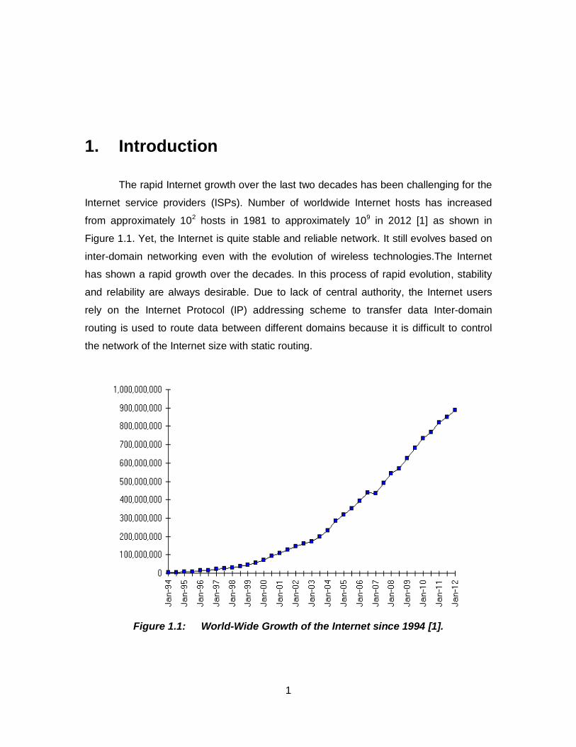
The rapid Internet growth over the last two decades has been challenging for the
Internet service providers (ISPs). Number of worldwide Internet hosts has increased
from approximately 102 hosts in 1981 to approximately 109 in 2012 [1] as shown in
Figure 1.1. Yet, the Internet is quite stable and reliable network. It still evolves based on
inter-domain networking even with the evolution of wireless technologies.The Internet
has shown a rapid growth over the decades. In this process of rapid evolution, stability
and relability are always desirable. Due to lack of central authority, the Internet users
rely on the Internet Protocol (IP) addressing scheme to transfer data Inter-domain
routing is used to route data between different domains because it is difficult to control
the network of the Internet size with static routing.
Figure 1.1: World-Wide Growth of the Internet since 1994 [1].
2
Border Gateway Protocol (BGP) is the de facto inter-domain Internet routing
protocol. BGP was developed in 1989 and has undergone several modifications since
then. Current version of BGP is known as BGP4 [2] and was modified to account for the
challenges arising from the Internet growth.
BGP routing tables store the information about the change of the routes and BGP
selects the best possible path based on these changes. In large networks, physical link
and router failures over a period of time cause changes in attribute of routing tables.
When a link or a router recovers from the failure, routers send updates to a routing table
for availability of route, which may cause route fluctuation. This may happen due to
misconfiguration of the routers. Routing policies between Autonomous Systems (ASes)
may contribute to the exchange of withdrawal and re-announcement update messages.
Route Flap Damping (RFD) is a technique developed to counter the BGP route
fluctuation caused by router configuration errors, transient data link failures, wrong policy
implementation, or software defects. The exchange of withdrawals and re-
announcement messages causes a change in route attribute and it is known as a flap.
RFD configuration includes number of parameters and a penalty that is assigned for
each route. With the occurrence of each route flap, the penalty value of a route
increases and route advertisements are suppressed when the threshold suppress limit is
exceeded. Once suppressed, the route will not be advertised in further announcements.
The route penalty of the suppressed route decreases exponentially based on the
exponential decay algorithm. A route may participate in the advertisement event and the
BGP decision process after the route penalty decreases below the threshold value.
RFD algorithms are deployed to improve the BGP convergence time. However,
BGP policies are configured without considering the BGP convergence. These policies
are the trade-offs imposed by the ISPs for exchanging large traffic volume. Based on the
BGP policies, ISPs may deny or allow any updates from a particular AS depending on
the policy between ASes. That may cause route oscillations and could, therefore, be
detected by the RFD mechanisms. To avoid such complications, the ISPs prefer not to
use RFD in their networks.
3
1.1. Contribution
1.1.1. Implementation of BGP policies in ns-2.34
We imported the policy module from the SSFNet simulation tool to an existing ns-
BGP model that was developed for the ns-2 network simulator. Several RFD algorithms
have been implemented in the ns-BGP module [3]. In this project, we implemented
modifications to the RFD algorithm and the maximum suppress threshold.
1.1.2. Analysis of RFD algorithms with modified maximum suppress value and BGP policies
The RFD algorithms were implemented in ns-2.34 using various maximum
suppress values. We have also analyzed the behavior of RFD algorithms with
implemented BGP policies. We used two network topology generators and the BCNET
routing tables to build networks for the simulation scenarios.
1.2. Thesis outline
The Thesis is organized as follows:
Chapter 2 provides brief introduction to ASes, BGP, the BGP routing process,
routing policies, convergence time, and previous work. Chapter 3 begins with
implementation of the BGP routing policies and RFD in ns-2.34, brief description of the
ns-2 simulator, structure of routing and routing policies used in the ns-2 implementation,
features of the ns-BGP, and simulation tests. Chapter 4 emphasizes the details of
network topology generators used in simulations. In Chapter 5, we have described the
Georgia Tech Inter−network Topology Model (GT-ITM) generator and the Boston
University Topology Representative Internet Topology generator (BRITE), routing
updates inter-arrival time, simulation run time, simulation settings, and the simulation
results without BGP routing policy. In Chapter 6 and Chapter 7, we analyzed the BCNET
traffic routes with implemented RFD algorithms and the proposed modified values of the
maximum suppress threshold. We conclude the Thesis with Chapter 8.
4
2. Internet Routing
Routers are the devices used to direct data packets in the Internet. Based on the
incoming traffic, routers maintain the route information in the routing tables based on the
best route decisions taken according to BGP. Internet instabilities that affect these
routing decisions may be due to either hardware or software related issues. They may
cause route oscillation in the network. Route Flap Damping (RFD) techniques were
introduced to overcome these issues. In this Section, we provide background information
about de-facto Internet routing protocol BGP, Internet instabilities, RFD, RFD algorithms,
and BGP policies.
2.1. Autonomous Systems
In the ideal Internet, routers are connected to end-points in a well-connected
graph to allow peers to exchange information using Internet protocols as well as provide
connectivity to the global network. In an ideal view of the Internet, it would be easy to
design algorithms to detect route faults and perform load-balancing on congested paths
in order to improve the network convergence time. However, the Internet is not simple to
understand.
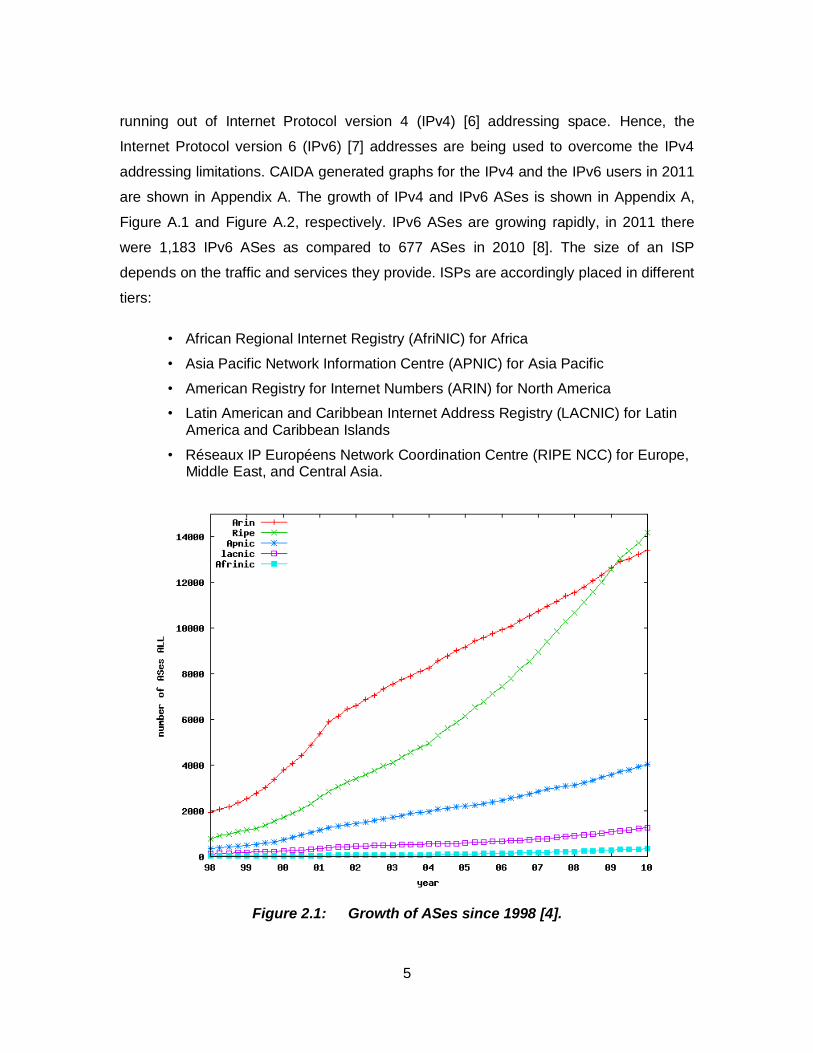
The growth of the number of ASes is shown in Figure 2.1.
The Cooperative Association for Internet Data Analysis (CAIDA) [4] recorded the growth
of ASes based on the registries with various registry networks. Réseaux IP Européens
(RIPE) and American Registry for Internet Numbers (ARIN) are the largest AS registry
networks. In 1998, ARIN had the largest number of registered ASes. However, since
2004, there has been an exponential growth in the RIPE network and it currently has the
largest number of ASes [4]. There are many service providers and most of the global
connectivity decisions are mainly based on the profit that ISPs may generate based on
their collaboration. The Internet Assigned Number Authority (IANA) [5] is currently
5
running out of Internet Protocol version 4 (IPv4) [6] addressing space. Hence, the
Internet Protocol version 6 (IPv6) [7] addresses are being used to overcome the IPv4
addressing limitations. CAIDA generated graphs for the IPv4 and the IPv6 users in 2011
are shown in Appendix A. The growth of IPv4 and IPv6 ASes is shown in Appendix A,
Figure A.1 and Figure A.2, respectively. IPv6 ASes are growing rapidly, in 2011 there
were 1,183 IPv6 ASes as compared to 677 ASes in 2010 [8]. The size of an ISP
depends on the traffic and services they provide. ISPs are accordingly placed in different
tiers:
• African Regional Internet Registry (AfriNIC) for Africa
• Asia Pacific Network Information Centre (APNIC) for Asia Pacific
• American Registry for Internet Numbers (ARIN) for North America
• Latin American and Caribbean Internet Address Registry (LACNIC) for Latin America and Caribbean Islands
• Réseaux IP Européens Network Coordination Centre (RIPE NCC) for Europe, Middle East, and Central Asia.
Figure 2.1: Growth of ASes since 1998 [4].
6
2.1.1. Classification of ISPs
Tier-1
ISPs belonging to Tier-1 are large service providers. They peer with other Tier-1
networks to ensure connectivity to the entire Internet.
Tier-2
Tier-2 ISPs are connected with at least one Tier-1 network to get transit services.
Tier-2 ISPs have to compensate Tier-1 networks that ensure their connectivity across
networks.
Tier-3
ISPs in Tier-3 are usually not multi-homed. They only have a single exchange
point to peer with other networks. To provide service in the regional area, a Tier-3 ISP
has to associate with either a Tier-2 or a Tier-1 transit service provider.
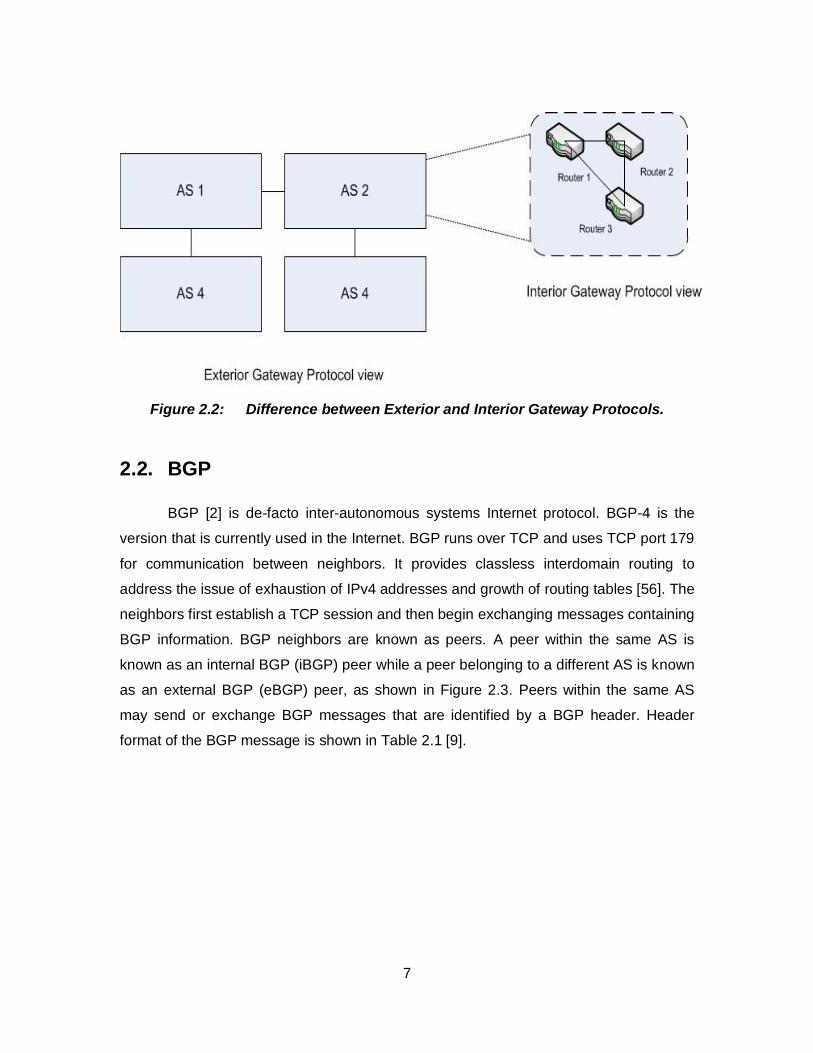
The current routing protocol architecture is defined by the ASes. An AS is given
to a particular university/company that decides how to share route information with other
ASes. The Internet routing protocol is employed to exchange reachability information
between ASes. The difference between Exterior Gateway Protocols (EGPs) and Interior
Gateway Protocols (IGPs) is shown in Figure 2.2.
Each AS has its own 16-bit identification number. Routing within an AS is
controlled with IGPs, while EGPs control the routing between ASes. Routing Information
Protocol (RIP), Open Shortest Path First (OSPF), Intermediate System to Intermediate
System (IS-IS), Interior Gateway Routing Protocol (IGRP), and Enhanced Interior
Gateway Routing Protocol (EIGRP) are interior routing protocols that operate within an
AS. BGP is the only exterior routing protocol currently employed in the Internet. IGPs
work well to optimize path metric of ASes while EGPs operate on accessibility
information and routing scalability [9].
7
Figure 2.2: Difference between Exterior and Interior Gateway Protocols.
2.2. BGP
BGP [2] is de-facto inter-autonomous systems Internet protocol. BGP-4 is the
version that is currently used in the Internet. BGP runs over TCP and uses TCP port 179
for communication between neighbors. It provides classless interdomain routing to
address the issue of exhaustion of IPv4 addresses and growth of routing tables [56]. The
neighbors first establish a TCP session and then begin exchanging messages containing
BGP information. BGP neighbors are known as peers. A peer within the same AS is
known as an internal BGP (iBGP) peer while a peer belonging to a different AS is known
as an external BGP (eBGP) peer, as shown in Figure 2.3. Peers within the same AS
may send or exchange BGP messages that are identified by a BGP header. Header
format of the BGP message is shown in Table 2.1 [9].
8
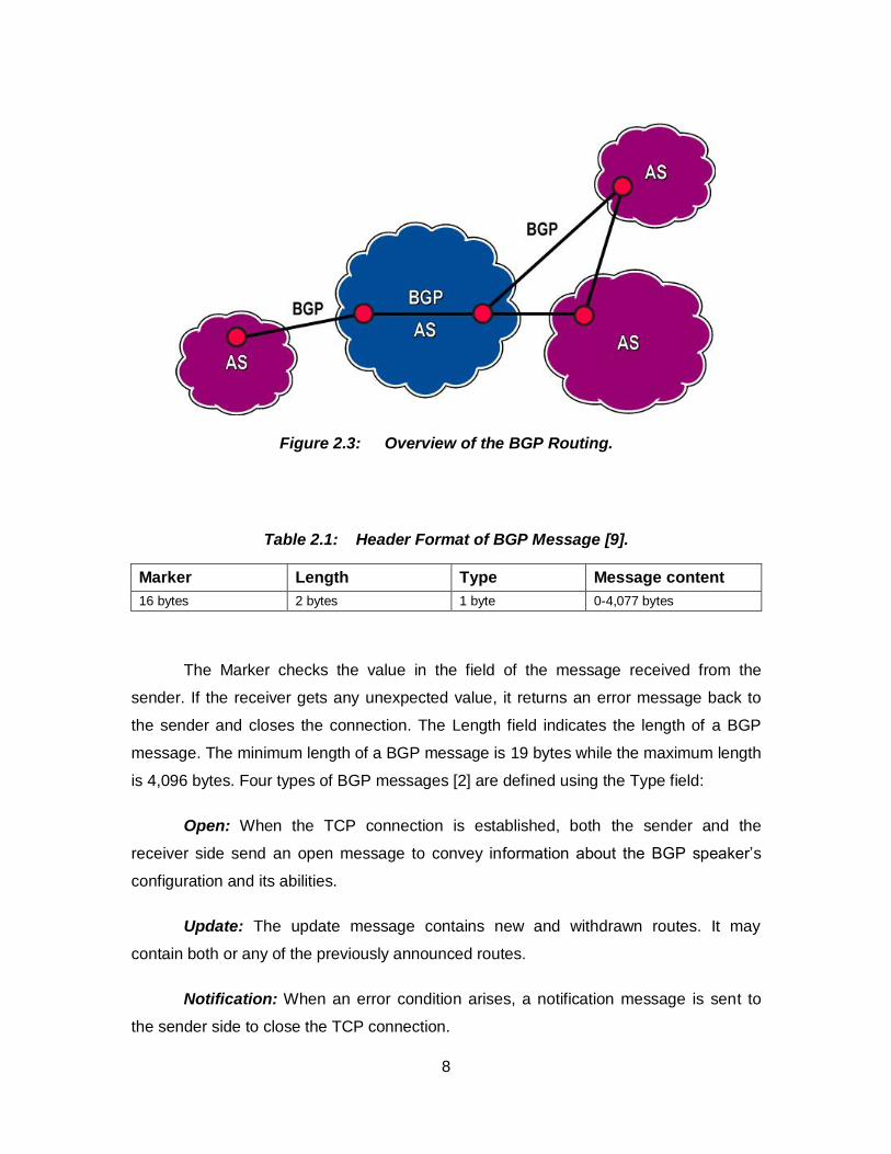
Figure 2.3: Overview of the BGP Routing.
Table 2.1: Header Format of BGP Message [9].
Marker Length Type Message content
16 bytes 2 bytes 1 byte 0-4,077 bytes
The Marker checks the value in the field of the message received from the
sender. If the receiver gets any unexpected value, it returns an error message back to
the sender and closes the connection. The Length field indicates the length of a BGP
message. The minimum length of a BGP message is 19 bytes while the maximum length
is 4,096 bytes. Four types of BGP messages [2] are defined using the Type field:
Open: When the TCP connection is established, both the sender and the
receiver side send an open message to convey information about the BGP speaker’s
configuration and its abilities.
Update: The update message contains new and withdrawn routes. It may
contain both or any of the previously announced routes.
Notification: When an error condition arises, a notification message is sent to
the sender side to close the TCP connection.
9
Keep alive: When the connection is in an idle state, a keep alive message is
sent to ensure that the hold timer does not expire.
2.3. BGP Routing Process and Decision Making
BGP4 defines the order to set up a BGP session between peers to begin
communication. The process of setting up a BGP session is:
1. According to the BGP4 [2], the BGP session may be in Idle, Connect Active, Open Sent, Open Confirm, or Established state.
2. In Idle state, the router does not set up a BGP session and waits for the BGP “start” event.
3. The router establishes TCP connection by listening to the incoming TCP sessions in the connect state.
4. BGP waits for a TCP session in the active state.
5. The open sent and open confirm states are used to exchange messages to complete a BGP session. After confirmations of open sent and open confirm states, a connection is ready for transmission of update, keep alive, and notification messages.
When the connection is established, only two types of update messages are
exchanged:
• Announcement messages are send to notify changes in the routes or announce new routes and withdrawal messages. They inform routers and/or receivers about availability of routes.
• A withdrawal of a route usually occurs when the routes announced earlier become unavailable due to network failure or a change in the BGP routing policy.
Traffic generated by BGP update messages is controlled by setting the Minimum
Route Advertisement Interval (MRAI) parameter. An update message should wait for the
time period equal to the MRAI value before sending new updates. The default value of
MRAI is 30 s. Hence, every message that has been sent has a life window of 30 s. A
BGP speaker waits for 30 s to receive a reply from destination before sending another
message [2].
10
The routes from update messages are stored in the Routing Information Base
(RIB). Outgoing update messages are stored in Adj-RIBs-Out, routes for local use are
stored in LOC-RIB, and incoming routes are stored in Adj-RIBs-In. BGP path attributes
are present in every update message as a variable length string. BGP path attributes [2]
are:
1. ORIGIN: AS uses the origin attribute to originate the routing
information to BGP speakers. All update messages use this attribute to send the information about the AS that issued it.
2. AS-Path: It contains the information in the form of AS sets and also the sequence of the ASes through which a route is passed. This attribute keeps changing with the change of routes or with the availability of new routes and unavailability of previously announced routes.
3. NEXT_HOP: This attribute contains the IP address of the router that may be used as the next hop towards reaching the destination. Router may be either within the same subnet or in another AS.
4. MULTI_EXIT_DISC: This attribute contains the information about the inter-AS routers and helps them to communicate with the neighboring ASes. This attribute helps the routers to decide through which neighboring routers the packets may be exchanged to the destination AS.
5. LOCAL_PREF: This important path attribute helps decide the preferred route. This attribute should only be added to a route for internal routing inside an AS. Route with the highest local preference should be preferred after calculating the degree of preference.
6. ATOMIC_AGGREGATOR: When a BGP speaker selects a less specific route rather than the more specific routes available from a set of overlapping routes from its peer, this attribute should be attached with the update message.
7. AGGREGATOR: This is an additional attribute to the update message. It should only be added by the BGP speakers that perform route aggregation.
BGP routing uses the best path selection algorithm by prioritizing the routes
according to the Degree of Preference (DoP) [2]:
• user-configured policies
• the highest local preference
11
• the shortest AS path
• the lowest MED.
Users may modify BGP routing decisions according to needs of the network. For
example, Cisco attaches additional attributes to the Cisco routers using the path attribute
to make it easier for customers to set up their routers.
2.4. Network Instability
Network stability is a very important Internet feature. Network instabilities may be
due to link failure, wrong router configuration, software problem, or malicious attacks.
They may cause delay in convergence time and delay in the propagation of the routes
throughout the Internet. As these attacks will change the preferred routes and announce
new routes to the destination, this contributes to route flapping. RFD algorithms were
designed to control the oscillation of routes due to these network failures [10].
When a network link fails or a policy changes, the announced route travels
through the Internet without reaching the destination. This overloads the other routers
and prolongs the convergence time. Due to overloading of the routers when the link
failure occurs, BGP path exploration becomes slower. Incorrect router software
implementations may cause similar problems because the configuration of two routers
would not match and the BGP speaker will announce routes that may never reach the
destination router.
Network instability may occur because of the denial of service (DoS) attacks [64].
In prefix hijacking attacks, attackers target the host with the AS prefixes that may look
like the legitimate route and all the ASes receiving this announcement will send traffic
towards a wrong AS. Attacker then may collect all the information directed towards this
bogus AS.
In similar type of attacks, Pakistan Telecomm used the “longest prefix rule” to
block YouTube access from Pakistan. Pakistan Telecomm AS 17557 announced a prefix
208.65.153.0/24, which was similar to YouTube AS 36561 prefix 208.65.152.0/12. The
Pacific Century CyberWorks (PCCW) Global AS 3491 forwarded the announcement to
12
the routers around the world. As the routes from AS 17557 had the longest prefix match,
all the Internet traffic was directed to Pakistan [11].
The DoS attacks may be used to compromise confidentiality and integrity of the
BGP speakers. Attackers may sniff personal information exchanged between two BGP
speakers, may modify the messages sent between two BGP speakers, and even add
fake messages.
DoS attackers may target TCP three-way handshake to perform the SYN
flooding attack. A router may transmit a number of SYN messages to the destination
router without completing the three-way handshake to establish the connection between
the receiver and the sender. This may open multiple TCP connections and may cause
the destination router to run out of the memory space, which may prevent the destination
router from completing any other transaction. The neighboring router will then consider
the destination router unreachable and will cause route flapping [12].
An attack on the physical link between two ASes may be directed through the
route path of the attacker’s choice. This may cause the routers to enter undesired
forwarding state where it becomes necessary to intervene and change these states.
Misconfiguration of the policies in BGP speakers may cause the instability because the
route would not reach the required destination thus causing the route oscillations [12].
Researchers have addressed the impact of BGP routing policies on the network during
the last decade. These studies have helped understand how BGP policies may cause
persistent oscillations [13].
2.5. Route Flap Damping (RFD) algorithms
RFD [10] is a technique used to detect route oscillations in a network and punish
the repeating routes [14]. RFD helps reduce routing traffic between the BGP peers. RFD
is designed to reduce the processing load of a router without affecting the BGP
convergence time and the overhead.
RFD algorithms define poorly behaved and well-behaved routes. If there is a
stable and an unstable route available for the same destination, then the unstable route
13
should be aggressively suppressed. Stable routes, however, should be processed
quickly. When unstable routes become stable, they should be considered in a BGP
decision. A flap [14] is defined for a route whose availability changes continuously over a
period of time and continuous advertisement, withdrawal, and re-advertisement
messages are exchanged with the neighboring routers. A penalty is assigned to a route
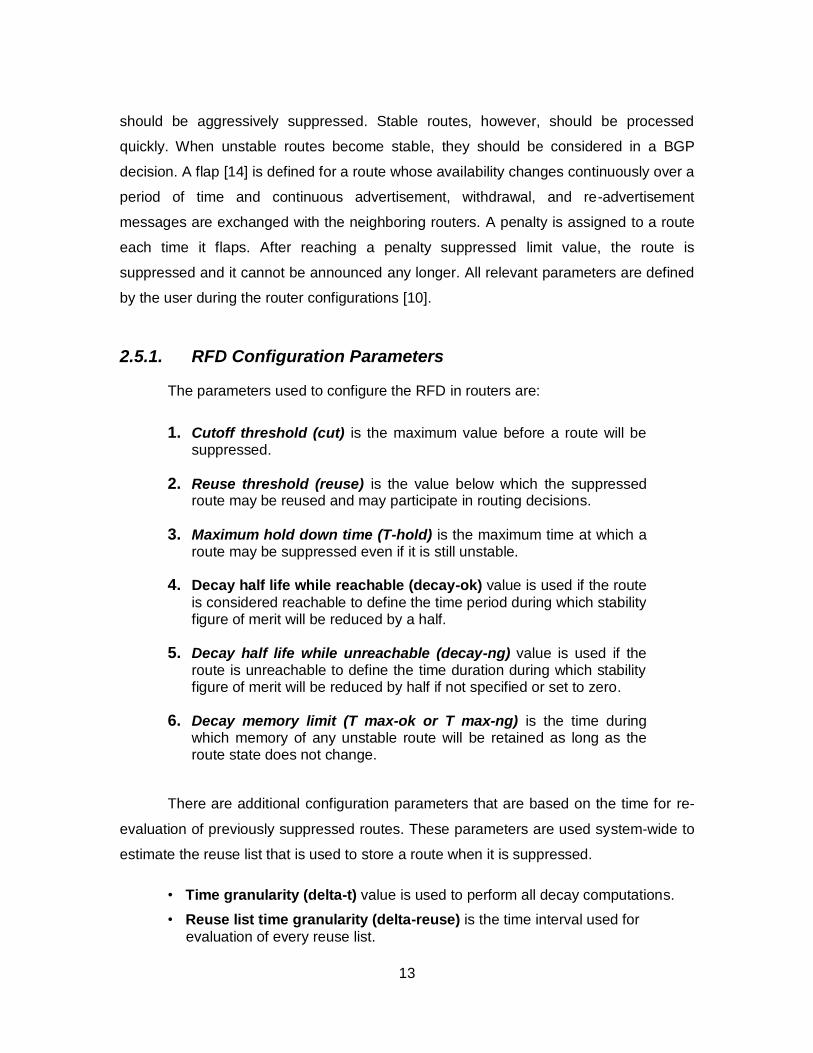
each time it flaps. After reaching a penalty suppressed limit value, the route is
suppressed and it cannot be announced any longer. All relevant parameters are defined
by the user during the router configurations [10].
2.5.1. RFD Configuration Parameters
The parameters used to configure the RFD in routers are:
1. Cutoff threshold (cut) is the maximum value before a route will be suppressed.
2. Reuse threshold (reuse) is the value below which the suppressed route may be reused and may participate in routing decisions.
3. Maximum hold down time (T-hold) is the maximum time at which a route may be suppressed even if it is still unstable.
4. Decay half life while reachable (decay-ok) value is used if the route
is considered reachable to define the time period during which stability figure of merit will be reduced by a half.
5. Decay half life while unreachable (decay-ng) value is used if the route is unreachable to define the time duration during which stability figure of merit will be reduced by half if not specified or set to zero.
6. Decay memory limit (T max-ok or T max-ng) is the time during which memory of any unstable route will be retained as long as the route state does not change.
There are additional configuration parameters that are based on the time for re-
evaluation of previously suppressed routes. These parameters are used system-wide to
estimate the reuse list that is used to store a route when it is suppressed.
• Time granularity (delta-t) value is used to perform all decay computations.
• Reuse list time granularity (delta-reuse) is the time interval used for
evaluation of every reuse list.
14
• Reuse list memory (reuse-list-max) is the maximum time value of T-hold parameter that corresponds to the last reuse list.
• Number of reuse lists (reuse-list-size) is the list that may be used according
to the value defined in parameter reuse-list-max.
Various algorithms have been designed to identify flaps and to assign penalties
to routes that are identified as flaps. We consider four algorithms that employ different
mechanisms to identify flaps. These RFD algorithms are:
2.5.2. Original RFD Algorithm
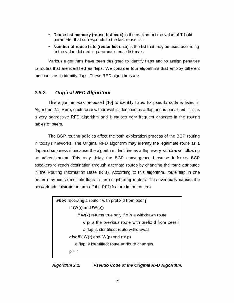
This algorithm was proposed [10] to identify flaps. Its pseudo code is listed in
Algorithm 2.1. Here, each route withdrawal is identified as a flap and is penalized. This is
a very aggressive RFD algorithm and it causes very frequent changes in the routing
tables of peers.
The BGP routing policies affect the path exploration process of the BGP routing
in today’s networks. The Original RFD algorithm may identify the legitimate route as a
flap and suppress it because the algorithm identifies as a flap every withdrawal following
an advertisement. This may delay the BGP convergence because it forces BGP
speakers to reach destination through alternate routes by changing the route attributes
in the Routing Information Base (RIB). According to this algorithm, route flap in one
router may cause multiple flaps in the neighboring routers. This eventually causes the
network administrator to turn off the RFD feature in the routers.
Algorithm 2.1: Pseudo Code of the Original RFD Algorithm.
when receiving a route r with prefix d from peer j
if (W(r) and !W(p))
// W(x) returns true only if x is a withdrawn route
// p is the previous route with prefix d from peer j
a flap is identified: route withdrawal
elseif (!W(r) and !W(p) and r ≠ p)
a flap is identified: route attribute changes
p = r
15
2.5.3. Selective RFD Algorithm
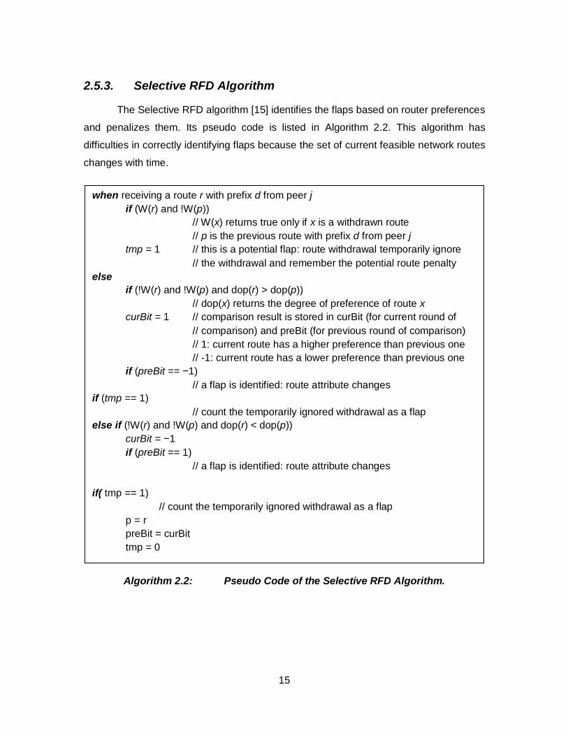
The Selective RFD algorithm [15] identifies the flaps based on router preferences
and penalizes them. Its pseudo code is listed in Algorithm 2.2. This algorithm has
difficulties in correctly identifying flaps because the set of current feasible network routes
changes with time.
Algorithm 2.2: Pseudo Code of the Selective RFD Algorithm.
when receiving a route r with prefix d from peer j
if (W(r) and !W(p))
// W(x) returns true only if x is a withdrawn route
// p is the previous route with prefix d from peer j
tmp = 1 // this is a potential flap: route withdrawal temporarily ignore
// the withdrawal and remember the potential route penalty
else
if (!W(r) and !W(p) and dop(r) > dop(p))
// dop(x) returns the degree of preference of route x
curBit = 1 // comparison result is stored in curBit (for current round of
// comparison) and preBit (for previous round of comparison)
// 1: current route has a higher preference than previous one
// -1: current route has a lower preference than previous one
if (preBit == −1)
// a flap is identified: route attribute changes
if (tmp == 1)
// count the temporarily ignored withdrawal as a flap
else if (!W(r) and !W(p) and dop(r) < dop(p))
curBit = −1
if (preBit == 1)
// a flap is identified: route attribute changes
if( tmp == 1)
// count the temporarily ignored withdrawal as a flap
p = r
preBit = curBit
tmp = 0
16
2.5.4. RFD+ Algorithm
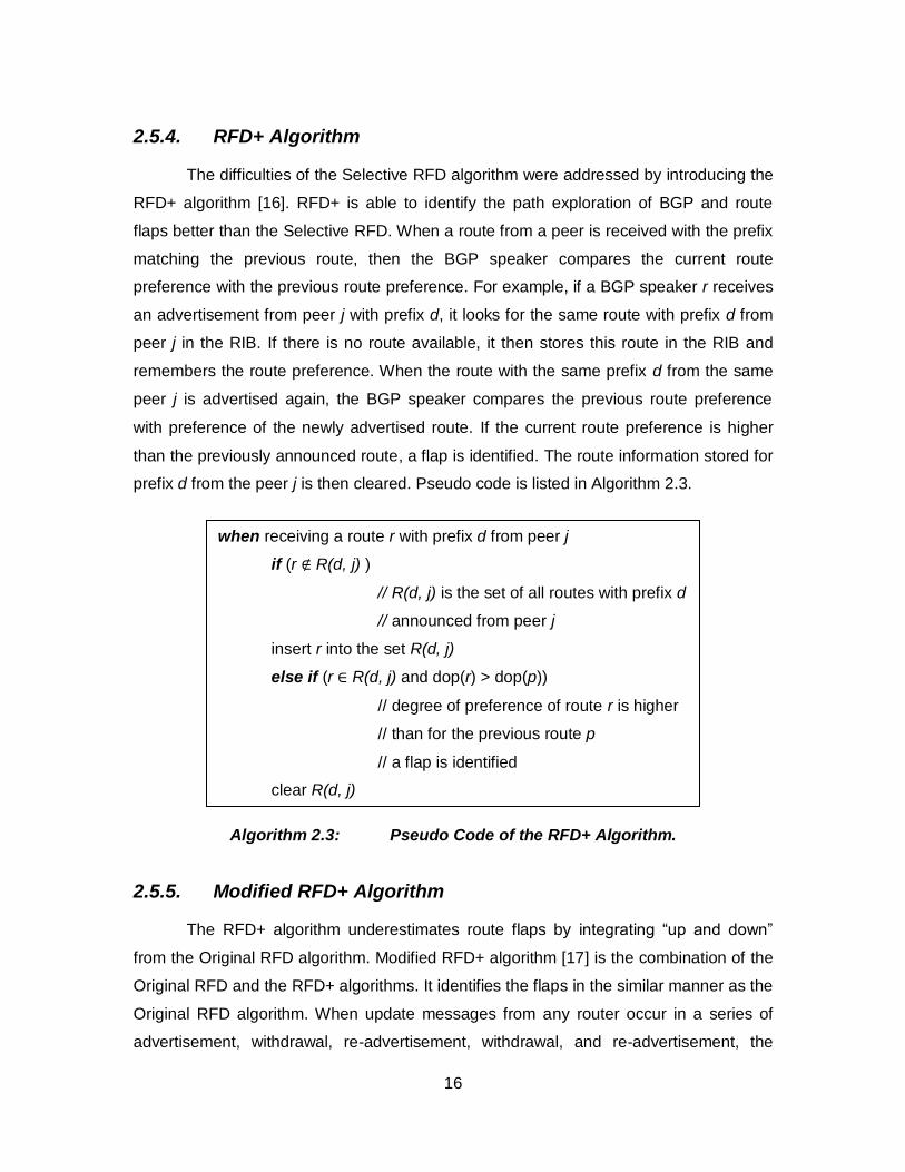
The difficulties of the Selective RFD algorithm were addressed by introducing the
RFD+ algorithm [16]. RFD+ is able to identify the path exploration of BGP and route
flaps better than the Selective RFD. When a route from a peer is received with the prefix
matching the previous route, then the BGP speaker compares the current route
preference with the previous route preference. For example, if a BGP speaker r receives
an advertisement from peer j with prefix d, it looks for the same route with prefix d from
peer j in the RIB. If there is no route available, it then stores this route in the RIB and
remembers the route preference. When the route with the same prefix d from the same
peer j is advertised again, the BGP speaker compares the previous route preference
with preference of the newly advertised route. If the current route preference is higher
than the previously announced route, a flap is identified. The route information stored for
prefix d from the peer j is then cleared. Pseudo code is listed in Algorithm 2.3.
Algorithm 2.3: Pseudo Code of the RFD+ Algorithm.
2.5.5. Modified RFD+ Algorithm
The RFD+ algorithm underestimates route flaps by integrating “up and down”
from the Original RFD algorithm. Modified RFD+ algorithm [17] is the combination of the
Original RFD and the RFD+ algorithms. It identifies the flaps in the similar manner as the
Original RFD algorithm. When update messages from any router occur in a series of
advertisement, withdrawal, re-advertisement, withdrawal, and re-advertisement, the
when receiving a route r with prefix d from peer j
if (r ∉ R(d, j) )
// R(d, j) is the set of all routes with prefix d
// announced from peer j
insert r into the set R(d, j)
else if (r ∈ R(d, j) and dop(r) > dop(p))
// degree of preference of route r is higher
// than for the previous route p
// a flap is identified
clear R(d, j)
17
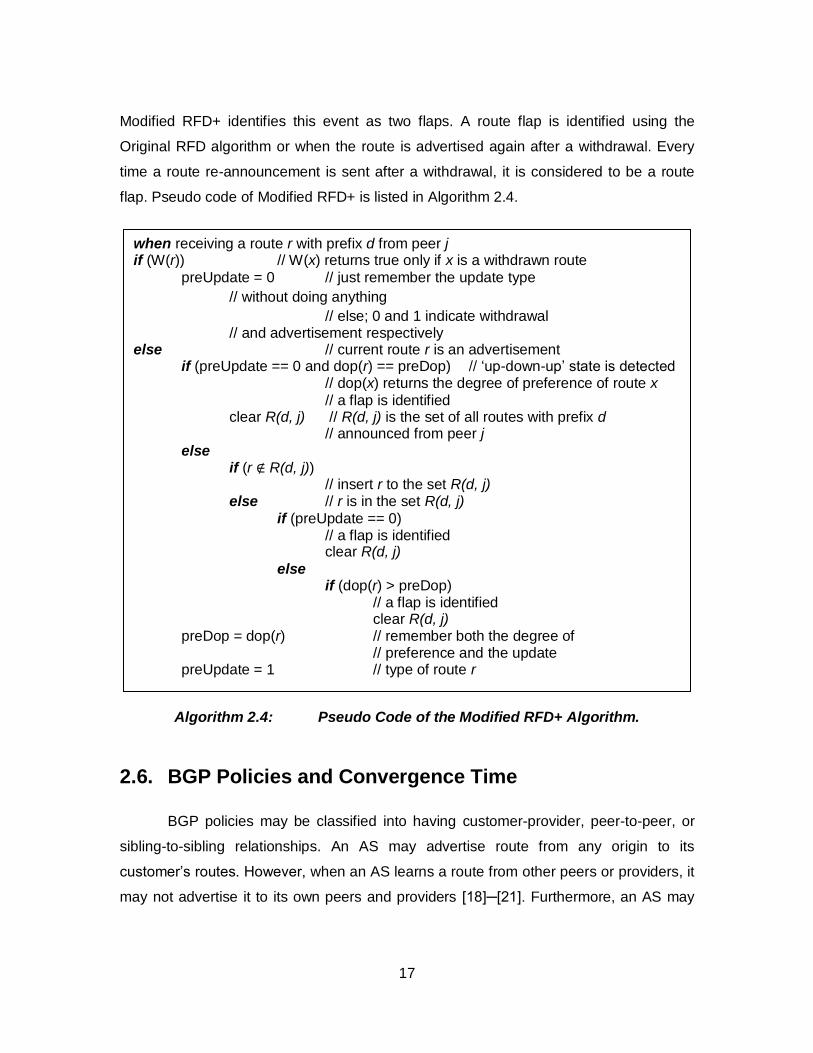
Modified RFD+ identifies this event as two flaps. A route flap is identified using the
Original RFD algorithm or when the route is advertised again after a withdrawal. Every
time a route re-announcement is sent after a withdrawal, it is considered to be a route
flap. Pseudo code of Modified RFD+ is listed in Algorithm 2.4.
Algorithm 2.4: Pseudo Code of the Modified RFD+ Algorithm.
2.6. BGP Policies and Convergence Time
BGP policies may be classified into having customer-provider, peer-to-peer, or
sibling-to-sibling relationships. An AS may advertise route from any origin to its
customer’s routes. However, when an AS learns a route from other peers or providers, it
may not advertise it to its own peers and providers [18]─[21]. Furthermore, an AS may
when receiving a route r with prefix d from peer j if (W(r)) // W(x) returns true only if x is a withdrawn route
preUpdate = 0 // just remember the update type
// without doing anything
// else; 0 and 1 indicate withdrawal // and advertisement respectively else // current route r is an advertisement if (preUpdate == 0 and dop(r) == preDop) // ‘up-down-up’ state is detected // dop(x) returns the degree of preference of route x
// a flap is identified clear R(d, j) // R(d, j) is the set of all routes with prefix d // announced from peer j
else if (r ∉ R(d, j)) // insert r to the set R(d, j) else // r is in the set R(d, j)
if (preUpdate == 0) // a flap is identified clear R(d, j)
else if (dop(r) > preDop) // a flap is identified clear R(d, j) preDop = dop(r) // remember both the degree of // preference and the update preUpdate = 1 // type of route r
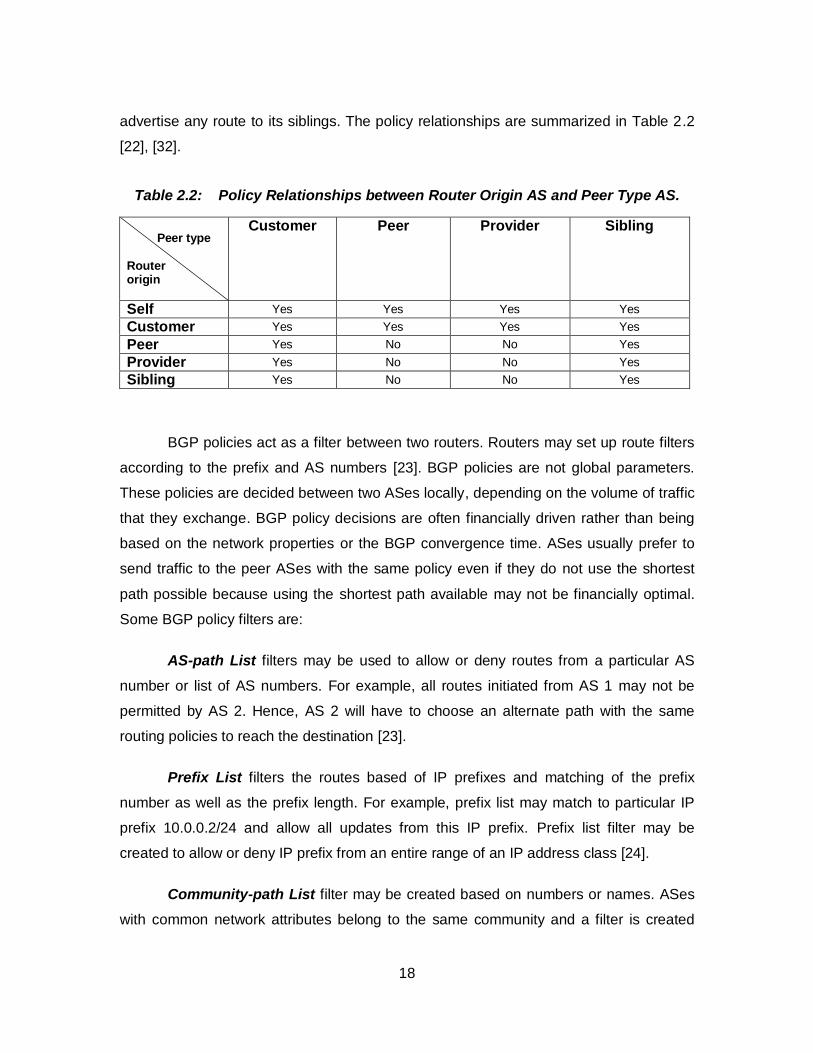
18
advertise any route to its siblings. The policy relationships are summarized in Table 2.2
[22], [32].
Table 2.2: Policy Relationships between Router Origin AS and Peer Type AS.
Peer type Router origin
Customer Peer Provider Sibling
Self Yes Yes Yes Yes
Customer Yes Yes Yes Yes
Peer Yes No No Yes
Provider Yes No No Yes
Sibling Yes No No Yes
BGP policies act as a filter between two routers. Routers may set up route filters
according to the prefix and AS numbers [23]. BGP policies are not global parameters.
These policies are decided between two ASes locally, depending on the volume of traffic
that they exchange. BGP policy decisions are often financially driven rather than being
based on the network properties or the BGP convergence time. ASes usually prefer to
send traffic to the peer ASes with the same policy even if they do not use the shortest
path possible because using the shortest path available may not be financially optimal.
Some BGP policy filters are:
AS-path List filters may be used to allow or deny routes from a particular AS
number or list of AS numbers. For example, all routes initiated from AS 1 may not be
permitted by AS 2. Hence, AS 2 will have to choose an alternate path with the same
routing policies to reach the destination [23].
Prefix List filters the routes based of IP prefixes and matching of the prefix
number as well as the prefix length. For example, prefix list may match to particular IP
prefix 10.0.0.2/24 and allow all updates from this IP prefix. Prefix list filter may be
created to allow or deny IP prefix from an entire range of an IP address class [24].
Community-path List filter may be created based on numbers or names. ASes
with common network attributes belong to the same community and a filter is created
19
based on these common attributes. Regular expressions are used to form these filters
[24].
There is no central authority to decide which routing policies should be
implemented in the network routers and there are no guidelines for setting up the
universal policy. This leads to persistent route oscillations in the network, which may
increase the number of updates and the traffic volume. The increase in number of
updates and traffic hampers the BGP convergence time. Routes selection does not
follow the shortest path possible because the presence of routing policies that may alter
the shortest path by imposing routing filters.
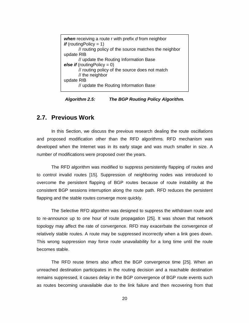
The algorithm for the policy filter is listed in Algorithm 2.5. Networks use the AS-
list policy to filter the BGP AS path attributes. In the AS-path list, network defines the
entire set of AS numbers that get approval to reach any particular network. The AS-path
list also helps the BGP in deciding the best available path. A regular expression string is
used to define the attribute pattern to deny or permit the list. Community-path list policy
may be of two types: numbered or named. Both identify and filter the routes according to
common attributes between two networks.
If a network has multiple routing policies, then routing policy module works
differently on the inbound updates. For inbound updates, first processes the filter list that
may deny access to any network. It then processes the route map and the type of policy
list. However, for outbound, the routing module processes the type of policy list first,
followed by the filter list and the route map [24].
20
Algorithm 2.5: The BGP Routing Policy Algorithm.
2.7. Previous Work
In this Section, we discuss the previous research dealing the route oscillations
and proposed modification other than the RFD algorithms. RFD mechanism was
developed when the Internet was in its early stage and was much smaller in size. A
number of modifications were proposed over the years.
The RFD algorithm was modified to suppress persistently flapping of routes and
to control invalid routes [15]. Suppression of neighboring nodes was introduced to
overcome the persistent flapping of BGP routes because of route instability at the
consistent BGP sessions interruption along the route path. RFD reduces the persistent
flapping and the stable routes converge more quickly.
The Selective RFD algorithm was designed to suppress the withdrawn route and
to re-announce up to one hour of route propagation [25]. It was shown that network
topology may affect the rate of convergence. RFD may exacerbate the convergence of
relatively stable routes. A route may be suppressed incorrectly when a link goes down.
This wrong suppression may force route unavailability for a long time until the route
becomes stable.
The RFD reuse timers also affect the BGP convergence time [25]. When an
unreached destination participates in the routing decision and a reachable destination
remains suppressed, it causes delay in the BGP convergence of BGP route events such
as routes becoming unavailable due to the link failure and then recovering from that
when receiving a route r with prefix d from neighbor
if (routingPolicy = 1) // routing policy of the source matches the neighbor update RIB // update the Routing Information Base else if (routingPolicy = 0)
// routing policy of the source does not match // the neighbor
update RIB // update the Routing Information Base
21
failure. The RFD+RG [26] is an RFD algorithm with a reachability guard algorithm that
was proposed to perform route flap damping without losing reachability of routes. It may
be employed with any RFD algorithm [26].
The persistent route oscillations may exist with a certain policy configuration that
may cause BGP stability [27]. Hop-by-hop inter-domain routing may not safely advertise
routes and, hence, for this purpose the shortest path route selection is considered to
have better performance. RFD may be used to detect route oscillations due to policy
configuration. With the introduction of the policy configuration, link state protocols may
have loops.
While BGP policies may cause instability and route oscillation in the network,
route oscillation may also occur even without the configuration of BGP policies [28]. The
occurrence of instability could also happen with the incorrect router configuration [29].
The increase of the damping suppresses the value of the threshold time and
makes the Original RFD algorithm less aggressive [27]. It will only suppress the routes
that may flap very frequently over a period of time without negatively affecting the BGP
convergence. Suppression of well-behaved routes may be prevented by increasing the
suppress threshold value because it will reduce inadequate suppression of frequently
used well-behaved routes.
22
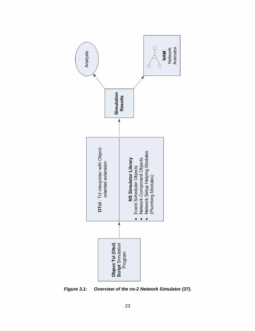
3. Implementation of BGP Routing Policies in ns-2
We implemented the BGP routing policies in the ns-2 network simulator. The ns-
BGP_2.0 [30] was ported to ns-2 from the SSFNET [31], [32] simulator. The MRAI
feature was then added [33]. RFD algorithms were implemented in the ns version ns-
2.27 [17]. We upgraded the RFD algorithms in the ns-2.34 [30], [34]. After upgrading the
RFD algorithms, we imported the BGP routing policy module from the SSFNET
simulator. We implemented two routing policies named AS-path and Community-path
lists in the routing policy module in ns-BGP-RP. To configure the routing policy module,
we imported the regular expression library tre-0.8.0 [35] in ns-2.34 and made changes in
the SSFNET code to compile it in ns-2.
3.1. The ns-2 Simulator
Ns-2 [36] is a discrete event simulator developed for network research. It is an
open source software. The ns-2 simulator was developed by the University of Southern
California, with the emphasis on modeling and analysis of network protocols such as
TCP, UDP, multicast, unicast, wireless, wired, and satellite. It is used to compare various
routing protocols. The ns-2 consists of a network simulator and nam (Network Animator)
for visualizing the network topology. The pre-processing includes the traffic and topology
generators while the trace analysis is done as the post-processing. The ns-2 uses C++
for packet processing and OTcl for setting up simulation configuration. Tcl scripts are
used for creating the network topologies. Many topology generators are integrated with
the ns-2 simulator and are used to create network topologies for the simulation. Smaller
network topologies may be generated by creating simple Tcl script. The overview of the
ns-2 simulator is shown in Figure 3.1.
23
Figure 3.1: Overview of the ns-2 Network Simulator (37).
24
3.2. Structure of Routing and Routing Policies used in ns-2 Implementation
The structure of routing and routing policies in ns-2 is shown in Figure 6. It
consists of two planes:
• Forwarding plane is used to classify the packets and forward them to their destination according to the classification.
• Control plane is used to compute routes, maintain routing table, and for
implementation of routing algorithms to select route paths.
The classifier_ analyzes the incoming packet for the destination address. If the
node is the packet’s destination, it forwards the packet to the dmux_. Otherwise, the
classifier_ sends packet information to the dmux_ to forward the packet to the packet’s
destination port number. The forwarding plane consists of classifier and routing modules
while the control plane consists of route logic, route object, and routing protocol. The ns-
BGP module in ns-2.34 has five important classes [38]:
1. TcpSocket
2. IPv4
3. rtModule/BGP
4. rtProtoBGP
5. BGP_Timer.
The TcpSocket class is an Application Programming Interface (API) in the ns-
BGP implementation. It consists of bind, listen, connect, close, read, and write functions.
The rtProtoBGP class (Agent/rtProto/BGP) performs all BGP operations, establishes
BGP peer sessions, performs protocol decision, and stores routes in RIB. We modified
the rtProtoBGP to apply BGP policy rules in the decision making process of BGP
operations.
The Peer Entry class sets up and closes the peer sessions and stores the
address, route preference, and the route advertised by the peer. Peer Entry instances
contain AdjIn, AdjOut, and the BGP_Timer class for the BGP Routing Information Base
(RIB). The BGP_Timer class contains the information about the BGP timer used during
the peer entry instances between two BGP speakers.
25
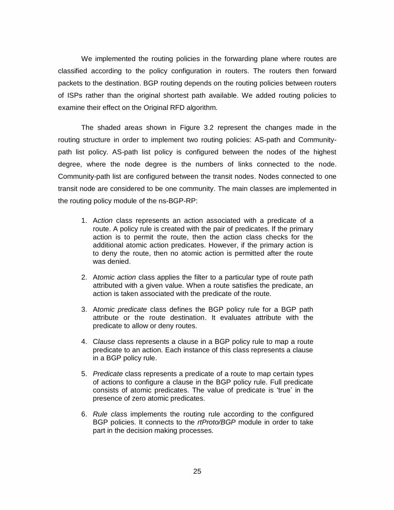
We implemented the routing policies in the forwarding plane where routes are
classified according to the policy configuration in routers. The routers then forward
packets to the destination. BGP routing depends on the routing policies between routers
of ISPs rather than the original shortest path available. We added routing policies to
examine their effect on the Original RFD algorithm.
The shaded areas shown in Figure 3.2 represent the changes made in the
routing structure in order to implement two routing policies: AS-path and Community-
path list policy. AS-path list policy is configured between the nodes of the highest
degree, where the node degree is the numbers of links connected to the node.
Community-path list are configured between the transit nodes. Nodes connected to one
transit node are considered to be one community. The main classes are implemented in
the routing policy module of the ns-BGP-RP:
1. Action class represents an action associated with a predicate of a
route. A policy rule is created with the pair of predicates. If the primary action is to permit the route, then the action class checks for the additional atomic action predicates. However, if the primary action is to deny the route, then no atomic action is permitted after the route was denied.
2. Atomic action class applies the filter to a particular type of route path attributed with a given value. When a route satisfies the predicate, an action is taken associated with the predicate of the route.
3. Atomic predicate class defines the BGP policy rule for a BGP path attribute or the route destination. It evaluates attribute with the predicate to allow or deny routes.
4. Clause class represents a clause in a BGP policy rule to map a route
predicate to an action. Each instance of this class represents a clause in a BGP policy rule.
5. Predicate class represents a predicate of a route to map certain types
of actions to configure a clause in the BGP policy rule. Full predicate consists of atomic predicates. The value of predicate is ‘true’ in the presence of zero atomic predicates.
6. Rule class implements the routing rule according to the configured BGP policies. It connects to the rtProto/BGP module in order to take
part in the decision making processes.
26
Figure 3.2: Implementation of the Routing Policies and Modification of RFD Algorithms in the ns-BGP-RP Node with Shaded BGP modules.
27
We modified the peer-entry class to implement routing policy between the BGP
peers. DampInfo and ReuseTimer classes are used for RFD algorithms. The prefix
damping structure for a peer of a BGP speaker is stored in the DampInfo class. The
ReuseTimer class works on the timer of a route suppressed by RFD algorithms. This
class decides when a suppressed route may be re-advertised. An interim route array for
the RFD+ algorithm is maintained in the VecRoutes.
The global.h is used to define all BGP global variables. We modified the value of
the route suppress [20] in the global.h class to comply with the default Cisco RFD
settings.
3.3. ns-BGP-RP Features
The routing policy features are added to ns-BGP-RP along with already existing
features of the ns-BGP such as sender-side loop detection, withdrawal rate limiting,
unjittered MRAI, per-peer per-destination, and rate limiting. The ns-BGP-RP also
supports Route Reflection, Multiple Exit Discriminator, Aggregator, Community,
Originator ID, Cluster List Path attributes, and RFD as an optional feature. Routing
policies may be configured in the OTcl script for simulations without the need to
recompile the C++ code.
3.4. Simulation Validation Scenarios
3.4.1. RFD Algorithms
We tested the RFD algorithms with various network topologies [3] in order to
validate the software implementation. We compared ns-BGP-RP simulation results for a
2-node line, 4-node tree, 6-node clique, and 11-node fork topologies with the results
reported in the literature [3]. Tcl scripts of these topologies are given in the Appendix A.
The number of flaps for every network topology is shown in Table 3.1
28
Table 3.1: Results for RFD Test Scripts.
Topology type
Simulation time
Subsection in Appendix D
Reported results [3]
ns-BGP-RP results
Line 3,100 1 4 4
Tree 12,800 2 35 35
Clique 910 3 1 1
Fork 250 4 2 2
3.4.2. AS-Path List Policy
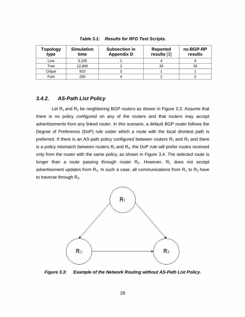
Let R1 and R2 be neighboring BGP routers as shown in Figure 3.3. Assume that
there is no policy configured on any of the routers and that routers may accept
advertisements from any linked router. In this scenario, a default BGP router follows the
Degree of Preference (DoP) rule under which a route with the local shortest path is
preferred. If there is an AS-path policy configured between routers R1 and R2 and there
is a policy mismatch between routers R1 and R3, the DoP rule will prefer routes received
only from the router with the same policy, as shown in Figure 3.4. The selected route is
longer than a route passing through router R3. However, R1 does not accept
advertisement updates from R3. In such a case, all communications from R1 to R3 have
to traverse through R2.
Figure 3.3: Example of the Network Routing without AS-Path List Policy.
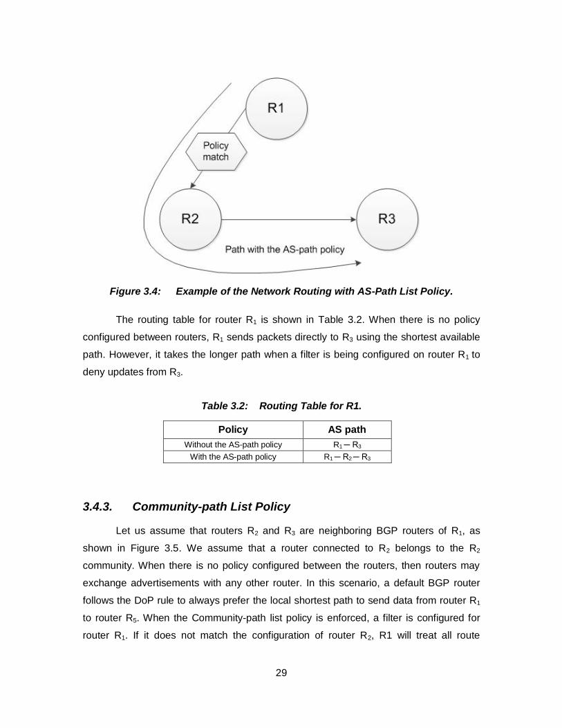
29
Figure 3.4: Example of the Network Routing with AS-Path List Policy.
The routing table for router R1 is shown in Table 3.2. When there is no policy
configured between routers, R1 sends packets directly to R3 using the shortest available
path. However, it takes the longer path when a filter is being configured on router R1 to
deny updates from R3.
Table 3.2: Routing Table for R1.
Policy AS path
Without the AS-path policy R1 ─ R3
With the AS-path policy R1 ─ R2 ─ R3
3.4.3. Community-path List Policy
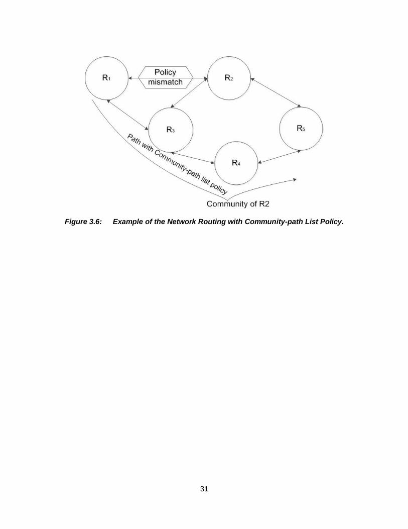
Let us assume that routers R2 and R3 are neighboring BGP routers of R1, as
shown in Figure 3.5. We assume that a router connected to R2 belongs to the R2
community. When there is no policy configured between the routers, then routers may
exchange advertisements with any other router. In this scenario, a default BGP router
follows the DoP rule to always prefer the local shortest path to send data from router R1
to router R5. When the Community-path list policy is enforced, a filter is configured for
router R1. If it does not match the configuration of router R2, R1 will treat all route
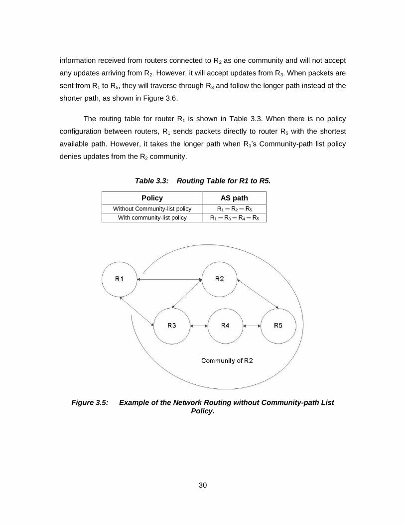
30
information received from routers connected to R2 as one community and will not accept
any updates arriving from R2. However, it will accept updates from R3. When packets are
sent from R1 to R5, they will traverse through R3 and follow the longer path instead of the
shorter path, as shown in Figure 3.6.
The routing table for router R1 is shown in Table 3.3. When there is no policy
configuration between routers, R1 sends packets directly to router R5 with the shortest
available path. However, it takes the longer path when R1’s Community-path list policy
denies updates from the R2 community.
Table 3.3: Routing Table for R1 to R5.
Policy AS path
Without Community-list policy R1 ─ R2 ─ R5
With community-list policy R1 ─ R3 ─ R4 ─ R5
Figure 3.5: Example of the Network Routing without Community-path List Policy.
31
Figure 3.6: Example of the Network Routing with Community-path List Policy.
32
4. Simulated Network Topologies
We used two topology generators to generate network topologies to evaluate the
performance of the RFD algorithms. The Georgia Tech Internetworks Topology Models
(GT-ITM) generator [39] and the Boston University Topology Representative Internet
Topology generator (BRITE) [40] were used to simulate various networks. We also
examined the routing tables of the BGP traffic data collected from BCNET [47] and
generated topology of the BCNET deployed network.
4.1. GT-ITM Topology Generator
The GT-ITM topology generator was developed by the Georgia Institute of
Technology. It may generate topologies with the flat random models, n-hierarchy
models, and transit-stub models. Six random models may be used to generate a network
topology [41], [42]:
1. Pure Random
2. Waxman1
3. Waxman2
4. DoarLeslie
5. Exponential
6. Locality.
Each model has is specific characteristics. Random models do not reflect the genuine
interworking structure. However, they are commonly used to examine networking
performance [41]. GT-ITM also generates network topologies using n-level and transit-
stub hierarchy models. The n-level hierarchy method connects all interconnecting nodes
to a connected flat random graph. Connected graphs are defined by the number of
levels [44].
33
The transit-stub model generates graphs that more closely match today’s Internet
topology. The model generates graphs with all edges connected and discards all the
unconnected graphs. This method utilizes the 2-level hierarchy where the first level
represents a transit domain and the second level represents the inter-domain
connectivity. The ASes in the stubs do not exchange traffic with the ASes in other stubs.
When required, the exchange of traffic has to be performed through the transit ASes.
The transit-stub model creates the network topology that has precise hierarchical
configuration comparable to the Internet tiers that allow a provider to divide traffic into
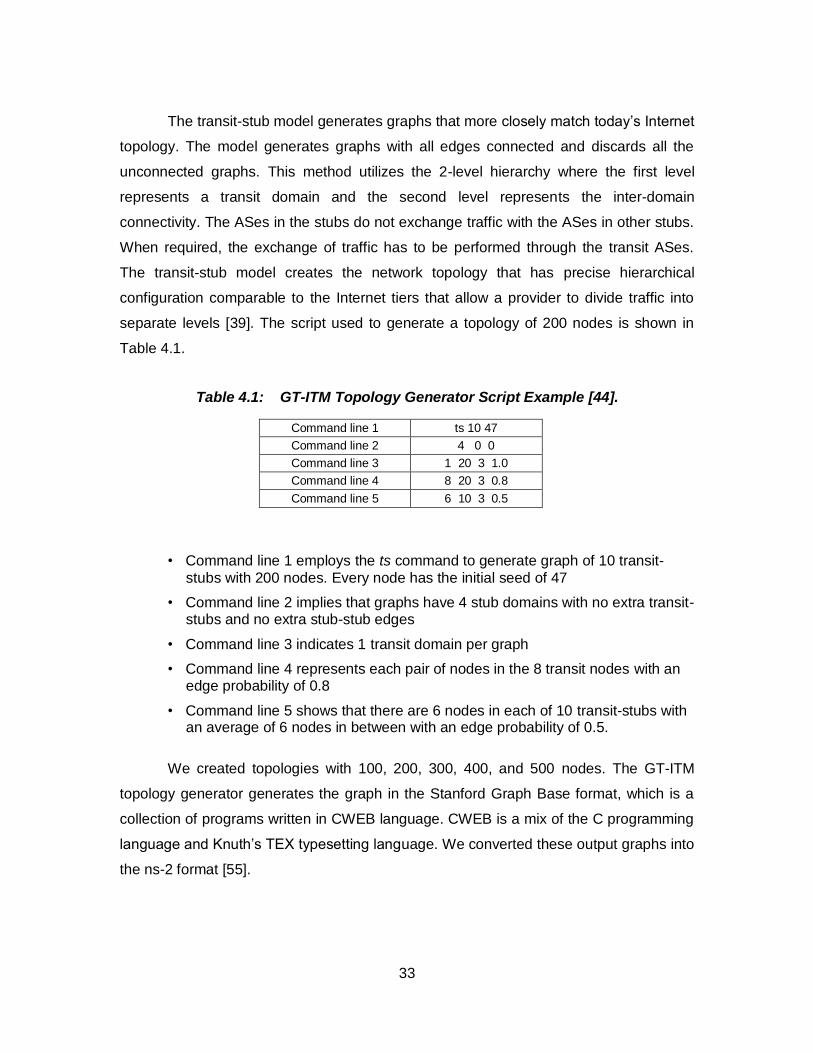
separate levels [39]. The script used to generate a topology of 200 nodes is shown in
Table 4.1.
Table 4.1: GT-ITM Topology Generator Script Example [44].
Command line 1 ts 10 47
Command line 2 4 0 0
Command line 3 1 20 3 1.0
Command line 4 8 20 3 0.8
Command line 5 6 10 3 0.5
• Command line 1 employs the ts command to generate graph of 10 transit-
stubs with 200 nodes. Every node has the initial seed of 47
• Command line 2 implies that graphs have 4 stub domains with no extra transit-stubs and no extra stub-stub edges
• Command line 3 indicates 1 transit domain per graph
• Command line 4 represents each pair of nodes in the 8 transit nodes with an edge probability of 0.8
• Command line 5 shows that there are 6 nodes in each of 10 transit-stubs with an average of 6 nodes in between with an edge probability of 0.5.
We created topologies with 100, 200, 300, 400, and 500 nodes. The GT-ITM
topology generator generates the graph in the Stanford Graph Base format, which is a
collection of programs written in CWEB language. CWEB is a mix of the C programming
language and Knuth’s TEX typesetting language. We converted these output graphs into
the ns-2 format [55].
34
4.2. BRITE Topology Generator
We used the BRITE network topology generator to create topologies that are
then compared with the GT-ITM topologies. BRITE generates a network topology by
placing the nodes in a plane, interconnecting those nodes, assigning attribute to the
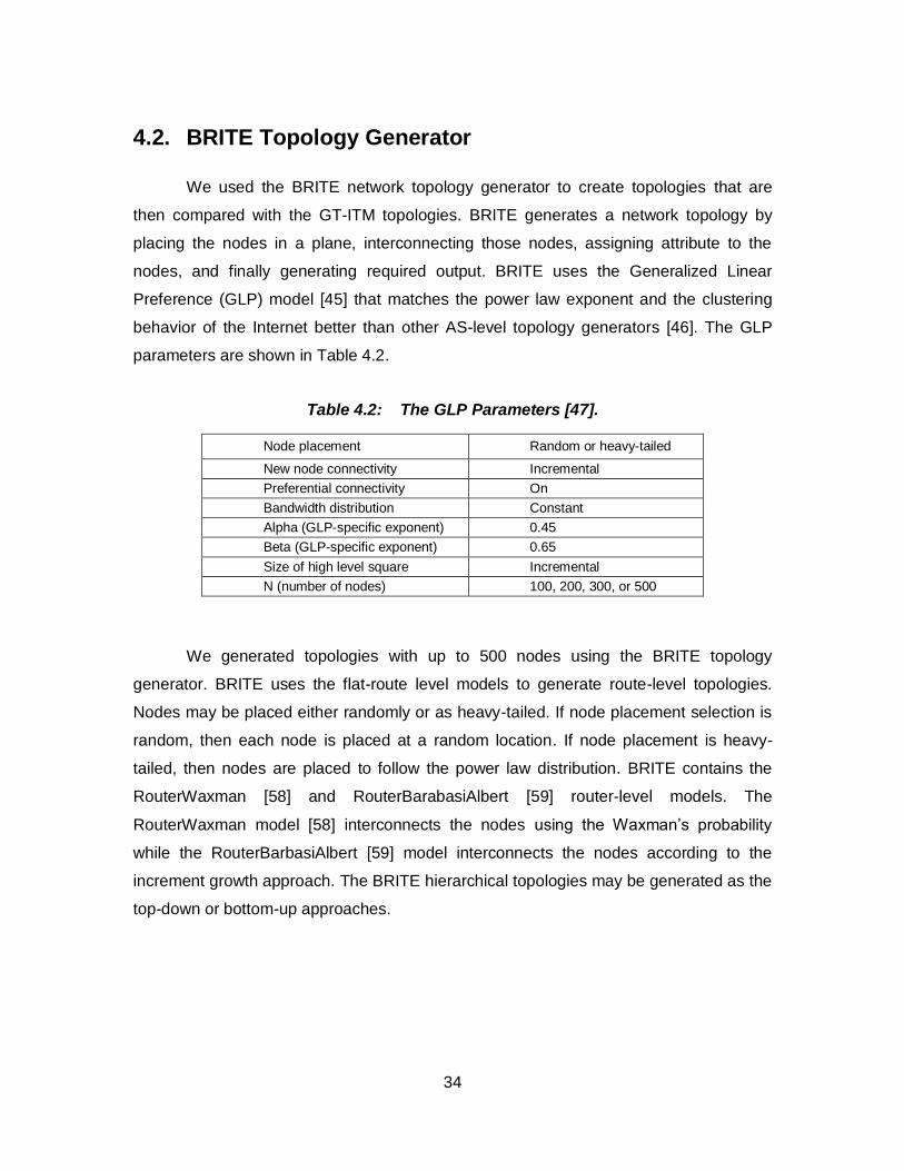
nodes, and finally generating required output. BRITE uses the Generalized Linear
Preference (GLP) model [45] that matches the power law exponent and the clustering
behavior of the Internet better than other AS-level topology generators [46]. The GLP
parameters are shown in Table 4.2.
Table 4.2: The GLP Parameters [47].
Node placement Random or heavy-tailed
New node connectivity Incremental
Preferential connectivity On
Bandwidth distribution Constant
Alpha (GLP-specific exponent) 0.45
Beta (GLP-specific exponent) 0.65
Size of high level square Incremental
N (number of nodes) 100, 200, 300, or 500
We generated topologies with up to 500 nodes using the BRITE topology
generator. BRITE uses the flat-route level models to generate route-level topologies.
Nodes may be placed either randomly or as heavy-tailed. If node placement selection is
random, then each node is placed at a random location. If node placement is heavy-
tailed, then nodes are placed to follow the power law distribution. BRITE contains the
RouterWaxman [58] and RouterBarabasiAlbert [59] router-level models. The
RouterWaxman model [58] interconnects the nodes using the Waxman’s probability
while the RouterBarbasiAlbert [59] model interconnects the nodes according to the
increment growth approach. The BRITE hierarchical topologies may be generated as the
top-down or bottom-up approaches.
35
4.3. BCNET Topology
We also used the BCNET traffic collection to generate 79 nodes graphs from the
collected Internet traffic data. These topologies were built [32], [47] by:
• creating a network topology extracted from a BGP routing table of the BCNET data
• placing nodes with the smallest degrees on a plane
• interconnecting the nodes and assigning the bandwidth according to the node degrees
• merging nodes with the smallest degree first.
We then analyzed the RFD algorithms using the connected sub-graphs of
genuine AS Internet topologies generated from collected BCNET data.
4.4. Inter-arrival time between Routing Update Messages
Inter-arrival time is the response time between advertisement updates from the
origin router. We selected different inter-arrival times for routing updates for a various
simulation scenarios. Inter-arrival time between the updates vary between very small
value of 30 s to a rather large value of 1,000 s. A simple simulation scenario consists of
the following steps:
1. set up BGP node and BGP agents
2. set up BGP neighbors according to the topology
3. BGP router A advertises a route R at time t (s)
4. BGP router A withdraws a route R at time t+i (s)
5. BGP router A re-advertises a route R at time t+2i (s)
6. simulation ends.
In simulation scenarios, the routers advertise the routes at the time t and then
withdraw the routes within the inter-arrival time i between the updates from routers.
Value i represents the time interval between advertised and withdrawn routes in the
network. This time may affect to the number of flaps in the simulation. However, it would
not affect the BGP convergence time [3].
36
4.5. Simulation Run Time
Simulation run time varies and depends on the simulation scenarios. It depends
on a number of factors such as:
1. Number of nodes in the network topology: As the number of nodes increases, requirement for additional memory space for the simulation increases.
2. Type of network topology: The ring, tree, and star topologies behave differently and may call for different simulation run time.
3. RFD route suppression value: This value defines the instant when a suppressed route may be reused again.
4. Type of flaps: The simulation time depends whether with the flaps are occasional or persistent.
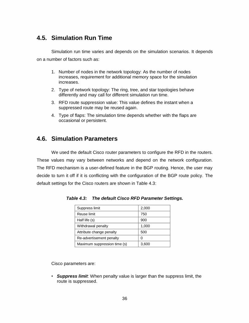
4.6. Simulation Parameters
We used the default Cisco router parameters to configure the RFD in the routers.
These values may vary between networks and depend on the network configuration.
The RFD mechanism is a user-defined feature in the BGP routing. Hence, the user may
decide to turn it off if it is conflicting with the configuration of the BGP route policy. The
default settings for the Cisco routers are shown in Table 4.3:
Table 4.3: The default Cisco RFD Parameter Settings.
Suppress limit 2,000
Reuse limit 750
Half life (s) 900
Withdrawal penalty 1,000
Attribute change penalty 500
Re-advertisement penalty 0
Maximum suppression time (s) 3,600
Cisco parameters are:
• Suppress limit: When penalty value is larger than the suppress limit, the route is suppressed.
37
• Reuse limit: When the penalty is smaller than the reuse limit, a route that has been suppressed may be announced again.
• Half-life time: The time required to reduce the penalty by one half.
• Withdrawal penalty: Penalty is assigned to a route when it is withdrawn.
• Attribute change penalty: Penalty is assigned to a route when it changes the route attribute.
• Re-advertisement penalty: Penalty is assigned to a route when it advertises a previously announced route.
• Maximum suppression time: The time value to keep a route suppressed.
• History entry: Stores the route flap information when the route is down.
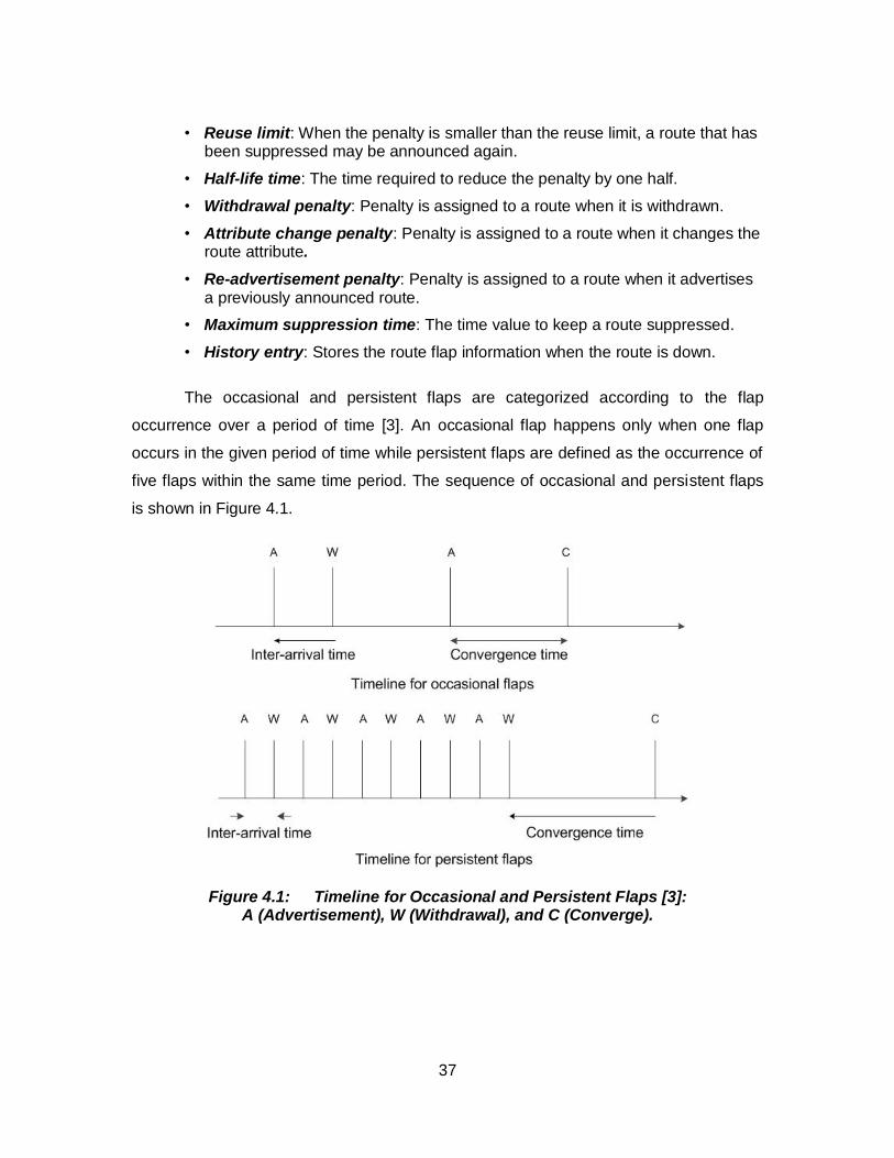
The occasional and persistent flaps are categorized according to the flap
occurrence over a period of time [3]. An occasional flap happens only when one flap
occurs in the given period of time while persistent flaps are defined as the occurrence of
five flaps within the same time period. The sequence of occasional and persistent flaps
is shown in Figure 4.1.
Figure 4.1: Timeline for Occasional and Persistent Flaps [3]: A (Advertisement), W (Withdrawal), and C (Converge).
38
5. Simulation Results
We analyzed the behavior of the Original RFD algorithm with and without BGP
routing policies and characterize the results according to:
1. total number of updates during simulation time
2. BGP convergence time
3. number of flaps
4. number of suppressed routes
5. size and shape of network topologies generated using various network topology generators
6. effect of routing policies
7. number of flaps with various values for route maximum suppression.
5.1. Comparison of BGP Modules With and Without Policies
In this Section, we compare the BGP modules with and without policies. The AS-
path list policy shows behavior similar to BGP without routing policies compared to the
Community-path list policy. We observed the BGP network convergence time for each
node as well as the overall BGP convergence time, number of updates, number of flaps,
and number of suppressed routes. For the comparison, we generated network
topologies using the GT-ITM topology generator. The BGP network converges when
routers stop sending AS route update messages. The advertisement and withdrawal
phases of the route update messages keep information about number of updates, flaps,
and route suppressions. A BGP speaker convergence time depends on the origin of the
incoming routes and location of routers. The network topologies used in simulations are
given in Table 5.1.
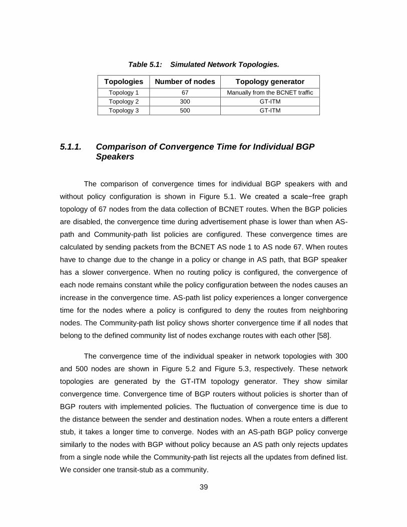
39
Table 5.1: Simulated Network Topologies.
Topologies Number of nodes Topology generator
Topology 1 67 Manually from the BCNET traffic
Topology 2 300 GT-ITM
Topology 3 500 GT-ITM
5.1.1. Comparison of Convergence Time for Individual BGP Speakers
The comparison of convergence times for individual BGP speakers with and
without policy configuration is shown in Figure 5.1. We created a scale−free graph
topology of 67 nodes from the data collection of BCNET routes. When the BGP policies
are disabled, the convergence time during advertisement phase is lower than when AS-
path and Community-path list policies are configured. These convergence times are
calculated by sending packets from the BCNET AS node 1 to AS node 67. When routes
have to change due to the change in a policy or change in AS path, that BGP speaker
has a slower convergence. When no routing policy is configured, the convergence of
each node remains constant while the policy configuration between the nodes causes an
increase in the convergence time. AS-path list policy experiences a longer convergence
time for the nodes where a policy is configured to deny the routes from neighboring
nodes. The Community-path list policy shows shorter convergence time if all nodes that
belong to the defined community list of nodes exchange routes with each other [58].
The convergence time of the individual speaker in network topologies with 300
and 500 nodes are shown in Figure 5.2 and Figure 5.3, respectively. These network
topologies are generated by the GT-ITM topology generator. They show similar
convergence time. Convergence time of BGP routers without policies is shorter than of
BGP routers with implemented policies. The fluctuation of convergence time is due to
the distance between the sender and destination nodes. When a route enters a different
stub, it takes a longer time to converge. Nodes with an AS-path BGP policy converge
similarly to the nodes with BGP without policy because an AS path only rejects updates
from a single node while the Community-path list rejects all the updates from defined list.
We consider one transit-stub as a community.
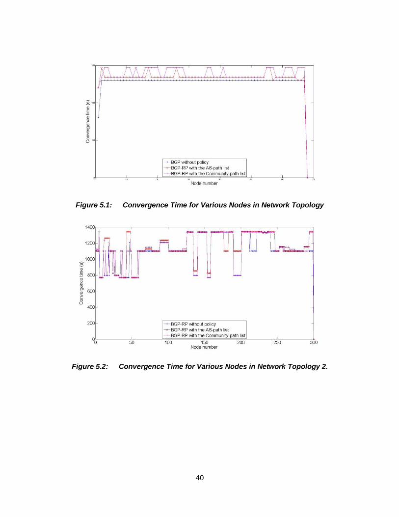
40
Figure 5.1: Convergence Time for Various Nodes in Network Topology
Figure 5.2: Convergence Time for Various Nodes in Network Topology 2.
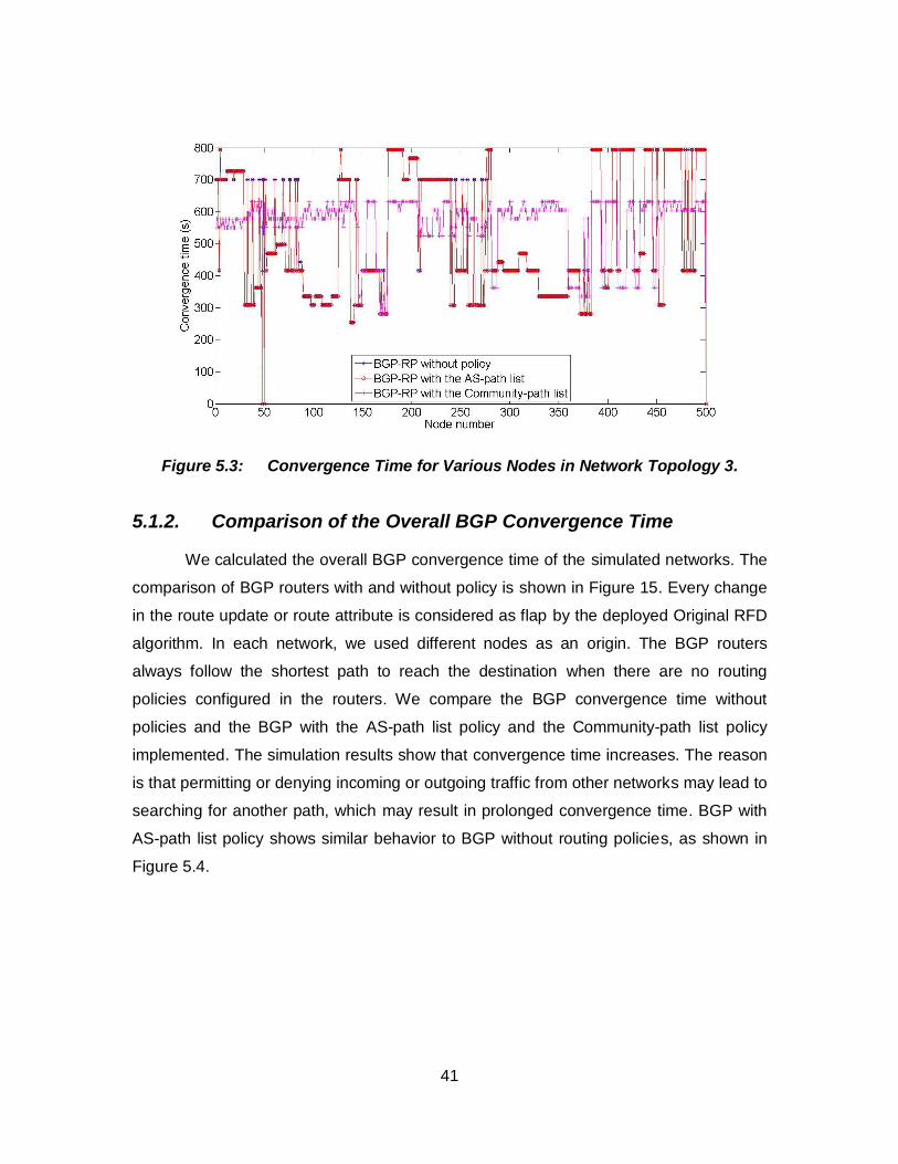
41
Figure 5.3: Convergence Time for Various Nodes in Network Topology 3.
5.1.2. Comparison of the Overall BGP Convergence Time
We calculated the overall BGP convergence time of the simulated networks. The
comparison of BGP routers with and without policy is shown in Figure 15. Every change
in the route update or route attribute is considered as flap by the deployed Original RFD
algorithm. In each network, we used different nodes as an origin. The BGP routers
always follow the shortest path to reach the destination when there are no routing
policies configured in the routers. We compare the BGP convergence time without
policies and the BGP with the AS-path list policy and the Community-path list policy
implemented. The simulation results show that convergence time increases. The reason
is that permitting or denying incoming or outgoing traffic from other networks may lead to
searching for another path, which may result in prolonged convergence time. BGP with
AS-path list policy shows similar behavior to BGP without routing policies, as shown in
Figure 5.4.
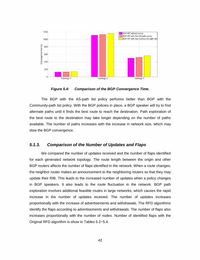
42
Figure 5.4: Comparison of the BGP Convergence Time.
The BGP with the AS-path list policy performs better than BGP with the
Community-path list policy. With the BGP policies in place, a BGP speaker will try to find
alternate paths until it finds the best route to reach the destination. Path exploration of
the best route to the destination may take longer depending on the number of paths
available. The number of paths increases with the increase in network size, which may
slow the BGP convergence.
5.1.3. Comparison of the Number of Updates and Flaps
We compared the number of updates received and the number of flaps identified
for each generated network topology. The route length between the origin and other
BGP routers affects the number of flaps identified in the network. When a route changes,
the neighbor router makes an announcement to the neighboring routers so that they may
update their RIB. This leads to the increased number of updates when a policy changes
in BGP speakers. It also leads to the route fluctuation in the network. BGP path
exploration involves additional feasible routes in large networks, which causes the rapid
increase in the number of updates received. The number of updates increases
proportionally with the increase of advertisements and withdrawals. The RFD algorithms
identify the flaps according to advertisements and withdrawals. The number of flaps also
increases proportionally with the number of nodes. Number of identified flaps with the
Original RFD algorithm is show in Tables 5.2−5.4.
43
Table 5.2: Comparison of the Total Number of Received Updates.
Topology Total number of
updates received without policy
Total number of updates received with
the AS-path list
Total number of updates received with the Community-path
list
1 745 1,102 970
2 27,113 28,366 28,575
3 24,822 28,109 28,446
Table 5.3: Comparison of the Total Number of Identified Flaps.
Topology Total number of flaps identified without policy
Total number of flaps identified with the
AS-path list
Total number of flaps identified with the
Community-path list
1 302 437 430
2 16,062 15,879 20,257
3 19,225 18,552 20,258
Table 5.4: Comparison of the Total Number of Suppressed Flaps.
Topology Total number of
flaps suppressed without policy
Total number of flaps suppressed with the AS-path list policy
Total number of flaps suppressed with the Community-path list
1 0 1 1
2 977 977 979
3 1,308 1,288 1,314
44
6. The BCNET Traffic Routes
The BCNET network is high-speed fiber optic research network that facilitates
high-definition video-conferencing, remote research, virtual laboratories, distributed
computing, distant learning, and large-scale data transfers. It provides interconnections
between the BCNET transit exchanges, implementation of local peering to exchange the
routing information, and multi-homing services [48]. The BCNET network connects cities
such as Kamloops, Kelowna, Prince George, Vancouver, and Victoria. The BCNET
network covers Prince George and Victoria through Vancouver and contributes up to 72
wavelengths of capacity at the link speed of 10 Gbps. The BCNET network covers over
140 provincial universities and institute campus sites, provincial health centers, research
facilities, federal and provincial research labs, and colleges and schools that use the
Provincial Learning Network. BCNET is connected with the network alliance Canada’s
Advanced Research and Innovation Network (CANARIE), which connects Canada to the
United States through the Internet and to Europe through the Delivery of Advanced
Network Technology to Europe (DANTE). The BCNET traffic map shown in Figure 6.1
displays the real time network usage by the BCNET associates [48].
45
Figure 6.1. Real Time Network Usage by BCNET Members, Collected on Dec. 28, 2012 [49] (G: gigabytes and M: megabytes).
46
We collected the traffic data from BCNET [48], [50]. In this Chapter, we use the
collected data to evaluate identification of flaps by four routing algorithms:
1. Original RFD
2. Selective RFD
3. RFD+
4. Modified RFD+.
Table 6.1 and Table 6.2 show the collected routing information from AS 271
(BCNET) and list all the update messages that passed through AS 6327 (Shaw cable)
and AS 6453 (Bell Canada) as two traffic carriers for BCNET. Traffic was collected
during the 24 hours period. However, only the first 20 routes for each carrier from the
BGP data collection from BCNET are shown. AS-path attribute of the route with time and
type of the update already announced are also shown.
The routing table for AS 271 through the carrier AS 6327 along with various
prefixes assigned by the BCNET for the routes is shown in Table 6.1. The BCNET
network sends the updates with the various prefix values. The BCNET network routers
examine the route requested by the origin AS. If there are active routes available with
the other carrier of BCNET, they send that routing information to the sender router. For
example, at time 21:07:29, the sender asks for destination AS 45228. Since routing
information for this destination was stored at time 19:51:45, router returns the stored
routes. Only few prefixes are always active in the trace. All other routers remain quiet for
most of the time. The small portion of active prefixes generates large number of BGP
update messages [50], [51].
47
Table 6.1: A List of Updates for the First 20 Routes from AS 271 through AS 6327 with Various Prefixes.
Origin AS 271 Local Preference 100 From 207.23.253.2 Prefix :1.0.4.0/22 to 223.255.254.0/24
Date 2-11-2011 To 207.23.253.2
Time AS-path Updates: A (advertise) and W (withdraw).
09:35:16 6327 7473 38040 9737 56120 I A
03:18:40 6327 15412 18101 A
03:18:40 W
19:51:45 6327 9498 45528 45528 45528 45528 I A
19:51:45 6327 9498 45528 I A
06:16:06 6327 15412 18101 45528 I A
03:55:53 6327 3549 55410 45528 I A
09:33:16 6327 1273 37986 24186 45528 I A
17:07:45 6327 1273 37986 24186 45528 I A
09:33:16 6327 15412 18101 45528 I A
09:33:16 6327 1273 37986 24186 45528 I A
19:51:45 6327 9498 45528 I A
19:51:45 6327 15412 18101 45528 I A
02:51:47 6327 9498 9730 45528 I A
02:51:47 W
14:01:55 6327 15412 18101 45528 I A
03:55:51 6327 3491 55410 45528 I A
19:51:45 6327 9498 45528 45528 45528 45528 I A
21:07:29 6327 3491 55410 45528 I A
19:51:45 6327 9498 9730 45528 I A
In the case where the RFD is enabled on the BCNET network routers, the four
RFD algorithms identified flaps according to the AS-path preference metrics as:
1. Original RFD algorithm identifies 19 flaps
2. Selective RFD algorithm identifies 4 flaps
3. RFD+ algorithm identifies 2 flaps
4. Modified RFD+ algorithm identifies 2 flaps.
The routing table for AS 271 through the carrier AS 6453 with various prefixes
assigned by the BCNET for the routes is shown in Table 14. The maximum and
minimum AS path lengths of BGP routes are 4 and 2, respectively.
48
Table 6.2: A List of Updates for the First 20 Routes from AS 271 Through AS 6453 with Various Prefixes.
Origin AS 271 Local Preference 100 From 207.23.253.2 Prefix :1.0.4.0/22 to 223.255.254.0/24
Date 2-11-2011 To 216.6.0.0
Time AS-path Updates. A (advertise) and W (withdraw).
15:04:29 6453 7545 7545 7545 7545 7545 56203 I A
05:18:31 6453 2914 2519 I A
05:18:31 6453 2914 2519 I A
05:18:31 6453 2914 2519 I A
02:39:32 6453 4725 7670 18144 I A
00:02:38 6453 4725 I A
14:53:43 6453 2914 4641 38345 I A
14:53:43 6453 2914 4641 38345 I A
14:53:43 6453 2914 4641 38345 I A
20:47:49 6453 3320 7497 38345 I A
14:53:43 6453 2914 4641 38345 I A
14:53:43 6453 2914 4641 38345 I A
07:53:27 6453 38345 I A
14:53:43 6453 2914 4641 38345 I A
09:57:31 6453 38345 I A
14:53:43 6453 2914 4641 38345 I A
14:53:43 6453 2914 4641 38345 I A
20:47:49 6453 3320 7497 38345 A
07:35:33 6453 2914 4641 38345 I A
07:53:27 6453 38345 I A
The relationship between the BCNET and its customers is shown in Figure 6.2.
Also shown is the rank number of each peer connected to BCNET with their
geographical locations. The graph is centered on the BCNET AS 271, with the providers
placed above AS 271 and BCNET customers placed below AS 271. The thickness of
each connecting line represents the AS size of the neighboring customer and AS ranks.
BCNET is ranked 708 in the Internet with the AS degree of 21. AS rank is based on the
number ASes associated with BCNET while AS degree is calculated according to the
number of connections with providers, siblings, peers, and customers. Twenty customer
ASes are associated with BCNET network, which represents the AS cone 20 in Figure
6.2. The BCNET network has total of 21 ASes as providers, siblings, peers, and
customers. The AS rank software develop by CAIDA [52] is used to visualize
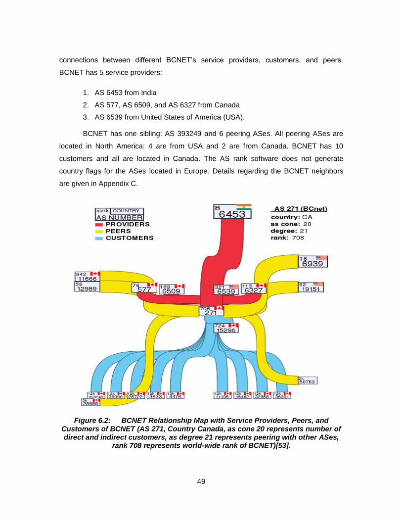
49
connections between different BCNET’s service providers, customers, and peers.
BCNET has 5 service providers:
1. AS 6453 from India
2. AS 577, AS 6509, and AS 6327 from Canada
3. AS 6539 from United States of America (USA).
BCNET has one sibling: AS 393249 and 6 peering ASes. All peering ASes are
located in North America: 4 are from USA and 2 are from Canada. BCNET has 10
customers and all are located in Canada. The AS rank software does not generate
country flags for the ASes located in Europe. Details regarding the BCNET neighbors
are given in Appendix C.
Figure 6.2: BCNET Relationship Map with Service Providers, Peers, and Customers of BCNET (AS 271, Country Canada, as cone 20 represents number of direct and indirect customers, as degree 21 represents peering with other ASes,
rank 708 represents world-wide rank of BCNET)[53].
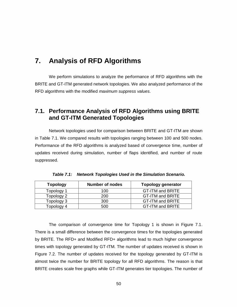
50
7. Analysis of RFD Algorithms
We perform simulations to analyze the performance of RFD algorithms with the
BRITE and GT-ITM generated network topologies. We also analyzed performance of the
RFD algorithms with the modified maximum suppress values.
7.1. Performance Analysis of RFD Algorithms using BRITE and GT-ITM Generated Topologies
Network topologies used for comparison between BRITE and GT-ITM are shown
in Table 7.1. We compared results with topologies ranging between 100 and 500 nodes.
Performance of the RFD algorithms is analyzed based of convergence time, number of
updates received during simulation, number of flaps identified, and number of route
suppressed.
Table 7.1: Network Topologies Used in the Simulation Scenario.
Topology Number of nodes Topology generator
Topology 1 100 GT-ITM and BRITE
Topology 2 200 GT-ITM and BRITE
Topology 3 300 GT-ITM and BRITE
Topology 4 500 GT-ITM and BRITE
The comparison of convergence time for Topology 1 is shown in Figure 7.1.
There is a small difference between the convergence times for the topologies generated
by BRITE. The RFD+ and Modified RFD+ algorithms lead to much higher convergence
times with topology generated by GT-ITM. The number of updates received is shown in
Figure 7.2. The number of updates received for the topology generated by GT-ITM is
almost twice the number for BRITE topology for all RFD algorithms. The reason is that
BRITE creates scale free graphs while GT-ITM generates tier topologies. The number of
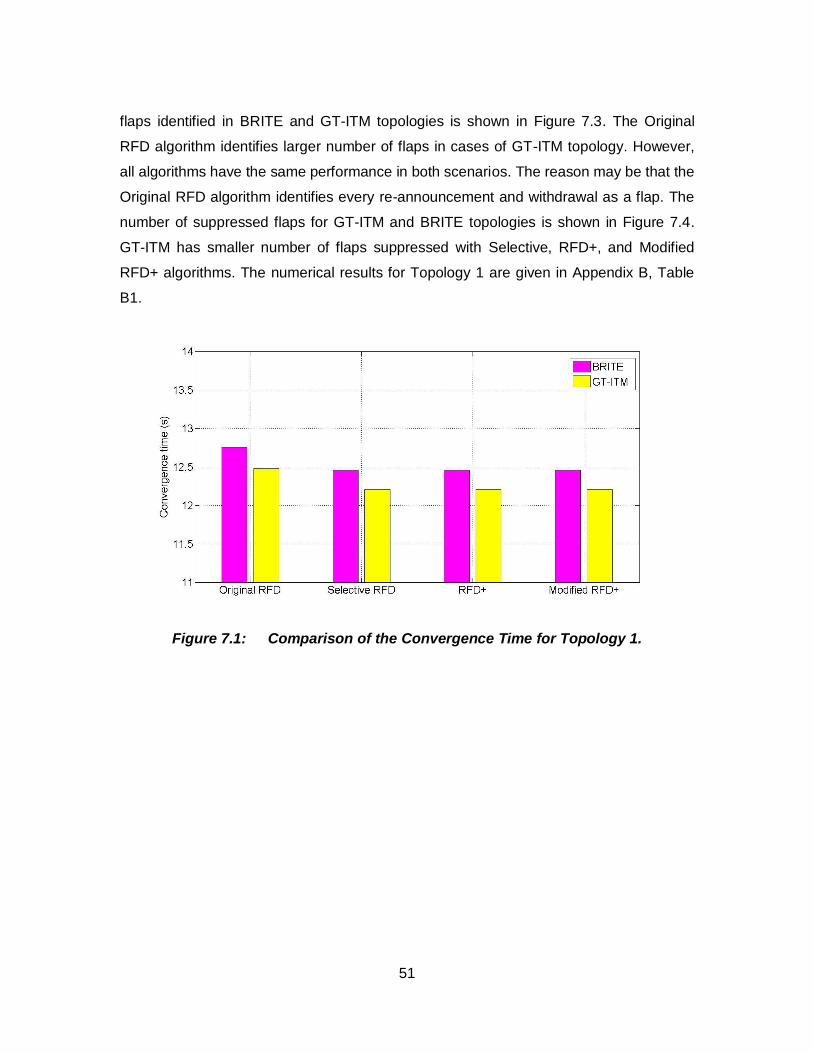
51
flaps identified in BRITE and GT-ITM topologies is shown in Figure 7.3. The Original
RFD algorithm identifies larger number of flaps in cases of GT-ITM topology. However,
all algorithms have the same performance in both scenarios. The reason may be that the
Original RFD algorithm identifies every re-announcement and withdrawal as a flap. The
number of suppressed flaps for GT-ITM and BRITE topologies is shown in Figure 7.4.
GT-ITM has smaller number of flaps suppressed with Selective, RFD+, and Modified
RFD+ algorithms. The numerical results for Topology 1 are given in Appendix B, Table
B1.
Figure 7.1: Comparison of the Convergence Time for Topology 1.
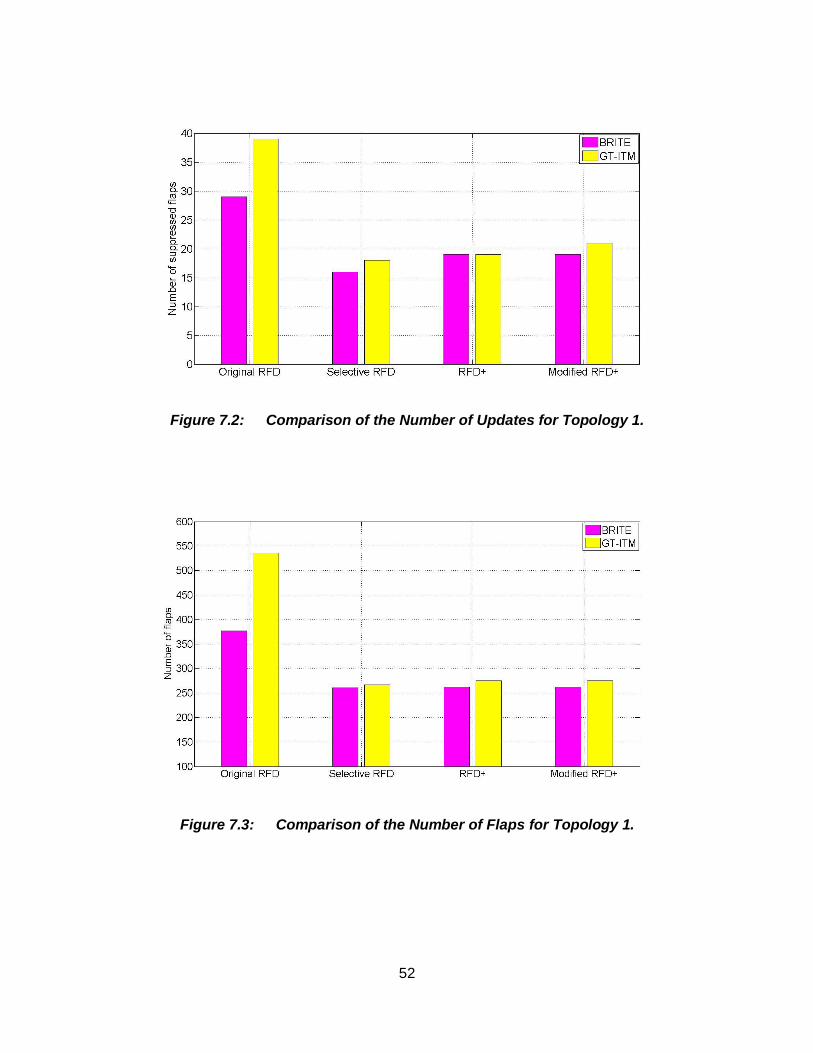
52
Figure 7.2: Comparison of the Number of Updates for Topology 1.
Figure 7.3: Comparison of the Number of Flaps for Topology 1.
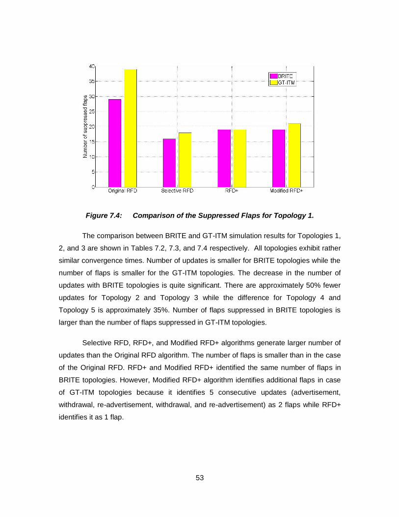
53
Figure 7.4: Comparison of the Suppressed Flaps for Topology 1.
The comparison between BRITE and GT-ITM simulation results for Topologies 1,
2, and 3 are shown in Tables 7.2, 7.3, and 7.4 respectively. All topologies exhibit rather
similar convergence times. Number of updates is smaller for BRITE topologies while the
number of flaps is smaller for the GT-ITM topologies. The decrease in the number of
updates with BRITE topologies is quite significant. There are approximately 50% fewer
updates for Topology 2 and Topology 3 while the difference for Topology 4 and
Topology 5 is approximately 35%. Number of flaps suppressed in BRITE topologies is
larger than the number of flaps suppressed in GT-ITM topologies.
Selective RFD, RFD+, and Modified RFD+ algorithms generate larger number of
updates than the Original RFD algorithm. The number of flaps is smaller than in the case
of the Original RFD. RFD+ and Modified RFD+ identified the same number of flaps in
BRITE topologies. However, Modified RFD+ algorithm identifies additional flaps in case
of GT-ITM topologies because it identifies 5 consecutive updates (advertisement,
withdrawal, re-advertisement, withdrawal, and re-advertisement) as 2 flaps while RFD+
identifies it as 1 flap.
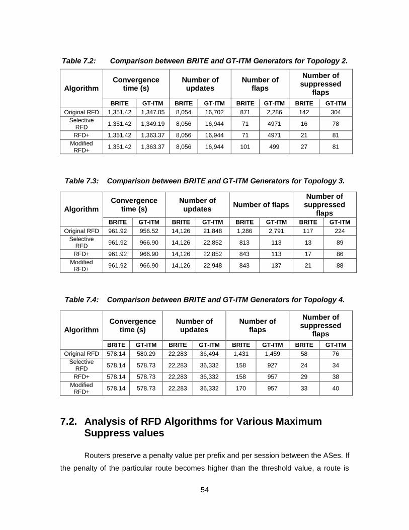
54
Table 7.2: Comparison between BRITE and GT-ITM Generators for Topology 2.
Algorithm Convergence
time (s) Number of
updates Number of
flaps
Number of suppressed
flaps
BRITE GT-ITM BRITE GT-ITM BRITE GT-ITM BRITE GT-ITM
Original RFD 1,351.42 1,347.85 8,054 16,702 871 2,286 142 304
Selective RFD
1,351.42 1,349.19 8,056 16,944 71 4971 16 78
RFD+ 1,351.42 1,363.37 8,056 16,944 71 4971 21 81
Modified RFD+
1,351.42 1,363.37 8,056 16,944 101 499 27 81
Table 7.3: Comparison between BRITE and GT-ITM Generators for Topology 3.
Algorithm
Convergence time (s)
Number of updates
Number of flaps Number of
suppressed flaps
BRITE GT-ITM BRITE GT-ITM BRITE GT-ITM BRITE GT-ITM
Original RFD 961.92 956.52 14,126 21,848 1,286 2,791 117 224
Selective RFD
961.92 966.90 14,126 22,852 813 113 13 89
RFD+ 961.92 966.90 14,126 22,852 843 113 17 86
Modified RFD+
961.92 966.90 14,126 22,948 843 137 21 88
Table 7.4: Comparison between BRITE and GT-ITM Generators for Topology 4.
Algorithm Convergence
time (s) Number of
updates Number of
flaps
Number of suppressed
flaps
BRITE GT-ITM BRITE GT-ITM BRITE GT-ITM BRITE GT-ITM
Original RFD 578.14 580.29 22,283 36,494 1,431 1,459 58 76
Selective RFD
578.14 578.73 22,283 36,332 158 927 24 34
RFD+ 578.14 578.73 22,283 36,332 158 957 29 38
Modified RFD+
578.14 578.73 22,283 36,332 170 957 33 40
7.2. Analysis of RFD Algorithms for Various Maximum Suppress values
Routers preserve a penalty value per prefix and per session between the ASes. If
the penalty of the particular route becomes higher than the threshold value, a route is
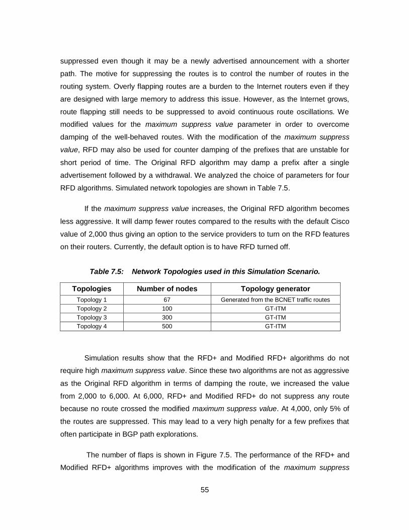
55
suppressed even though it may be a newly advertised announcement with a shorter
path. The motive for suppressing the routes is to control the number of routes in the
routing system. Overly flapping routes are a burden to the Internet routers even if they
are designed with large memory to address this issue. However, as the Internet grows,
route flapping still needs to be suppressed to avoid continuous route oscillations. We
modified values for the maximum suppress value parameter in order to overcome
damping of the well-behaved routes. With the modification of the maximum suppress
value, RFD may also be used for counter damping of the prefixes that are unstable for
short period of time. The Original RFD algorithm may damp a prefix after a single
advertisement followed by a withdrawal. We analyzed the choice of parameters for four
RFD algorithms. Simulated network topologies are shown in Table 7.5.
If the maximum suppress value increases, the Original RFD algorithm becomes
less aggressive. It will damp fewer routes compared to the results with the default Cisco
value of 2,000 thus giving an option to the service providers to turn on the RFD features
on their routers. Currently, the default option is to have RFD turned off.
Table 7.5: Network Topologies used in this Simulation Scenario.
Topologies Number of nodes Topology generator
Topology 1 67 Generated from the BCNET traffic routes
Topology 2 100 GT-ITM
Topology 3 300 GT-ITM
Topology 4 500 GT-ITM
Simulation results show that the RFD+ and Modified RFD+ algorithms do not
require high maximum suppress value. Since these two algorithms are not as aggressive
as the Original RFD algorithm in terms of damping the route, we increased the value
from 2,000 to 6,000. At 6,000, RFD+ and Modified RFD+ do not suppress any route
because no route crossed the modified maximum suppress value. At 4,000, only 5% of
the routes are suppressed. This may lead to a very high penalty for a few prefixes that
often participate in BGP path explorations.
The number of flaps is shown in Figure 7.5. The performance of the RFD+ and
Modified RFD+ algorithms improves with the modification of the maximum suppress
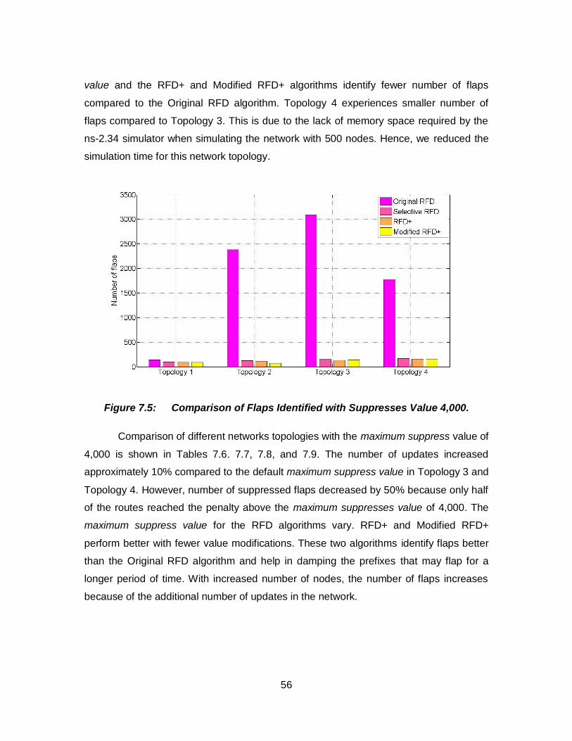
56
value and the RFD+ and Modified RFD+ algorithms identify fewer number of flaps
compared to the Original RFD algorithm. Topology 4 experiences smaller number of
flaps compared to Topology 3. This is due to the lack of memory space required by the
ns-2.34 simulator when simulating the network with 500 nodes. Hence, we reduced the
simulation time for this network topology.
Figure 7.5: Comparison of Flaps Identified with Suppresses Value 4,000.
Comparison of different networks topologies with the maximum suppress value of
4,000 is shown in Tables 7.6. 7.7, 7.8, and 7.9. The number of updates increased
approximately 10% compared to the default maximum suppress value in Topology 3 and
Topology 4. However, number of suppressed flaps decreased by 50% because only half
of the routes reached the penalty above the maximum suppresses value of 4,000. The
maximum suppress value for the RFD algorithms vary. RFD+ and Modified RFD+
perform better with fewer value modifications. These two algorithms identify flaps better
than the Original RFD algorithm and help in damping the prefixes that may flap for a
longer period of time. With increased number of nodes, the number of flaps increases
because of the additional number of updates in the network.
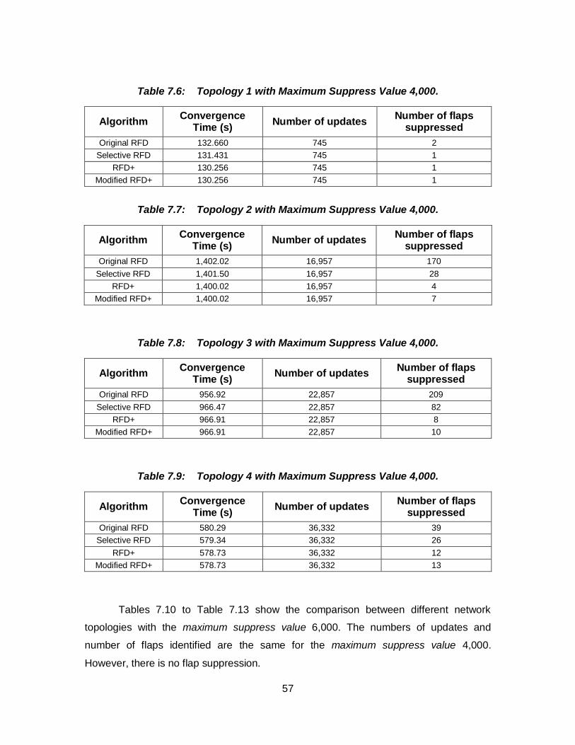
57
Table 7.6: Topology 1 with Maximum Suppress Value 4,000.
Algorithm Convergence
Time (s) Number of updates
Number of flaps suppressed
Original RFD 132.660 745 2
Selective RFD 131.431 745 1
RFD+ 130.256 745 1
Modified RFD+ 130.256 745 1
Table 7.7: Topology 2 with Maximum Suppress Value 4,000.
Algorithm Convergence
Time (s) Number of updates
Number of flaps suppressed
Original RFD 1,402.02 16,957 170
Selective RFD 1,401.50 16,957 28
RFD+ 1,400.02 16,957 4
Modified RFD+ 1,400.02 16,957 7
Table 7.8: Topology 3 with Maximum Suppress Value 4,000.
Algorithm Convergence
Time (s) Number of updates
Number of flaps suppressed
Original RFD 956.92 22,857 209
Selective RFD 966.47 22,857 82
RFD+ 966.91 22,857 8
Modified RFD+ 966.91 22,857 10
Table 7.9: Topology 4 with Maximum Suppress Value 4,000.
Algorithm Convergence
Time (s) Number of updates
Number of flaps suppressed
Original RFD 580.29 36,332 39
Selective RFD 579.34 36,332 26
RFD+ 578.73 36,332 12
Modified RFD+ 578.73 36,332 13
Tables 7.10 to Table 7.13 show the comparison between different network
topologies with the maximum suppress value 6,000. The numbers of updates and
number of flaps identified are the same for the maximum suppress value 4,000.
However, there is no flap suppression.
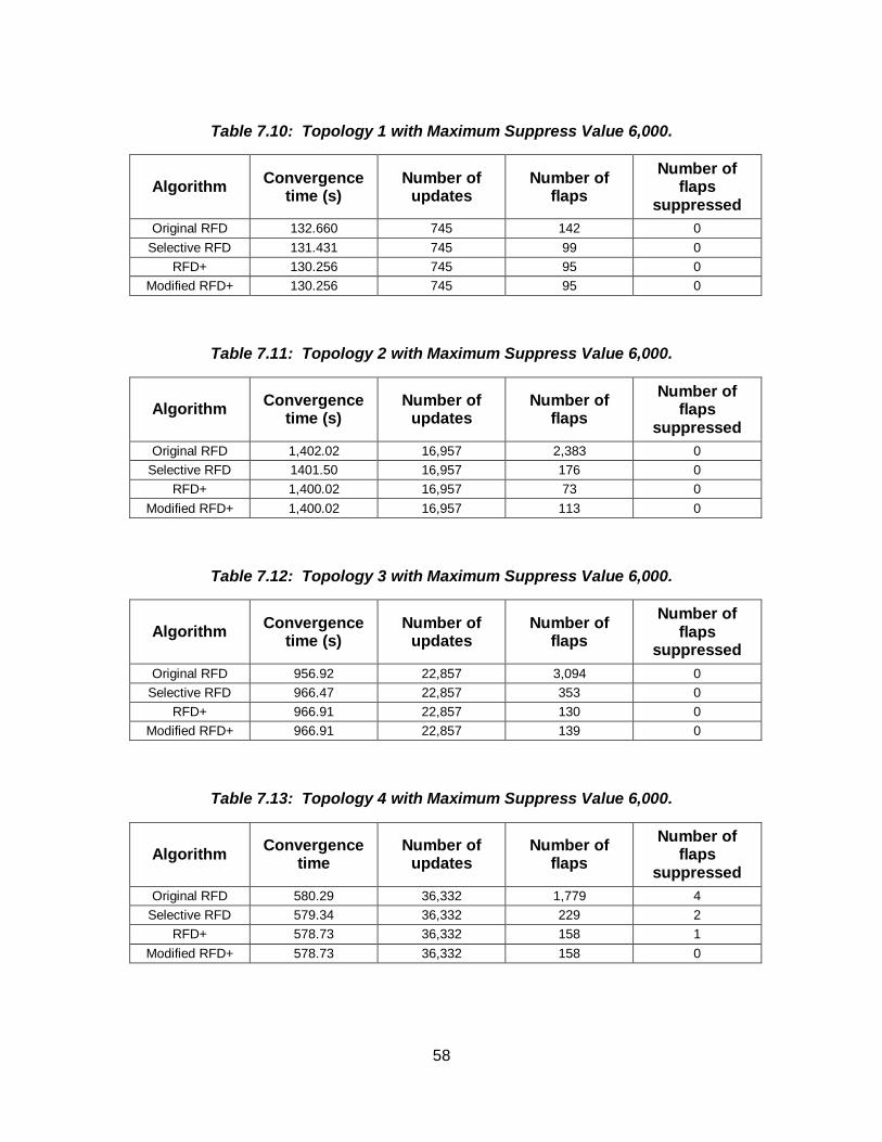
58
Table 7.10: Topology 1 with Maximum Suppress Value 6,000.
Algorithm Convergence
time (s) Number of
updates Number of
flaps
Number of flaps
suppressed
Original RFD 132.660 745 142 0
Selective RFD 131.431 745 99 0
RFD+ 130.256 745 95 0
Modified RFD+ 130.256 745 95 0
Table 7.11: Topology 2 with Maximum Suppress Value 6,000.
Algorithm Convergence
time (s) Number of
updates Number of
flaps
Number of flaps
suppressed
Original RFD 1,402.02 16,957 2,383 0
Selective RFD 1401.50 16,957 176 0
RFD+ 1,400.02 16,957 73 0
Modified RFD+ 1,400.02 16,957 113 0
Table 7.12: Topology 3 with Maximum Suppress Value 6,000.
Algorithm Convergence
time (s) Number of
updates Number of
flaps
Number of flaps
suppressed
Original RFD 956.92 22,857 3,094 0
Selective RFD 966.47 22,857 353 0
RFD+ 966.91 22,857 130 0
Modified RFD+ 966.91 22,857 139 0
Table 7.13: Topology 4 with Maximum Suppress Value 6,000.
Algorithm Convergence
time Number of
updates Number of
flaps
Number of flaps
suppressed
Original RFD 580.29 36,332 1,779 4
Selective RFD 579.34 36,332 229 2
RFD+ 578.73 36,332 158 1
Modified RFD+ 578.73 36,332 158 0
59
The change of the maximum suppress value may vary according to the traffic a
router receives and the configured policies. A router processing a heavy Internet traffic
may require higher suppression value while a router with lighter network traffic may
adjust the value to higher than the default value. As in the case of Topology 4 with 500
nodes, there are few suppressed routes with the maximum suppress value 6,000. This
number also depends on the RFD algorithm implemented in the router. If the Original
RFD algorithm is implemented, then the maximum suppress value needs to be higher
than in the case of Selective RFD, RFD+, and Modified RFD+ algorithms.
60
8. Conclusions
In this Thesis, we implemented a BGP module with routing policies in the ns-2
network simulator. The policies are imported from the SSFNET BGP-4 module. We
implemented the AS-path list and Community-path list filters in the BGP module.
We compared the performance of the BGP network without policy and the
network with the AS-path list and the Community-path list policies. Convergence time of
BGP with the AS-path policy is similar to the BGP without policy when compared to the
convergence time of BGP with the Community-path list policy. The number of updates
received and the number of flaps are also smaller in case of the AS-path policy. Network
routing policies increase convergence time, number of updates, and number of flaps.
BGP without a policy performs better than BGP with policies. However, most ISPs have
policies configured in ASes in order to exchange routes at low cost.
We compared the performance of the Original RFD, Selective RFD, RFD+, and
Modified RFD+ algorithms with topologies generated by BRITE and GT-ITM topology
generators. Original RFD may identify the flaps and may suppress the routes more
efficiently, which leads to the legitimate route suppression. BRITE generated topologies
have smaller number of updates and smaller number of flaps identified in the network
when compared to the GT-ITM generated topologies. Convergence time of GT-ITM
topologies is shorter than for the BRITE topologies while RFD+ and Modified RFD+ have
almost identical performance. However, they may suppress the persistent route flaps
slower than the Original RFD algorithm.
We evaluated performance of the Original RFD, Selective RFD, RFD+, and
Modified RFD+ algorithms with the various values of the maximum suppression RFD
parameter. The Modified RFD+ performed similarly to the RFD+. The increase of the
maximum suppression value parameter may be essential for today’s fast growing
Internet. The default values were set when the Internet was not as large as it is today.
61
Hence, these values may need to be modified to make the algorithms more useful to the
ISPs so that they may have better policy control of the network routers.
An adaptive approach to the route flap damping may help achieve an agreement
between the BGP policy configurations without adversely affecting the network stability
and network security. The RFD algorithms may also have to be redesigned in order to
identify the persistent route flapping caused by the Internet instabilities without causing
slower convergence.
62
References
1. The ISC Domain Survey [Online]. Available: https:\\www.isc.org/wordpress/solutions/domain-survey/
2. Y. Rekhter and T. Li, “A border gateway protocol 4 (BGP-4),” IETF RFC 1771, Mar.
1995.
3. W. Shen, BGP Route Flap Damping Algorithms, M.A.Sc. Thesis, SFU, Dec. 2005.
4. AS growth [online] Available: http:\\www.caida.org/research/routing/as_growth/.
5. Internet Assigned Numbers Authority [Online]. Available: http:\\www.iana.org/.
6. J. Postel, "Internet Protocol," IETF RFC 791, Sept. 1981.
7. S. Deering and R. Hinden, "Internet Protocol, version 6 (IPv6) specification," RFC 2460, Dec. 1998.
8. CAIDA’S IPv4 & IPv6 AS Core AS-level INTERNET GRAPH [Online]. Available: http:\\www.caida.org/research/topology/as_core_network/pics/ascore-2011-apr-ipv4v6-poster.pdf.
9. I. V. Beijnum, “The Internet, Routing, and BGP,” in BGP, Sebastopol, CA, O'Reilly Media, 2002, Ch. 2, Sec. 2.3, p. 19.
10. C. Villamizar, R. Chandra, and R. Govindan, “BGP route flap damping,” IETF RFC 2439, Nov. 1998.
11. YouTube Hijacking: A RIPE NCC RIS case study [online] Available: http:\\www.ripe.net/internet-coordination/news/industry-developments/youtube-hijacking-a-ripe-ncc-ris-case-study.
12. K. Varadhan, R. Govindan, and D. Estrin, “Persistent route oscillations in interdomain routing,” Computer Networks, vol. 32, no. 1, pp. 1–16, Jan. 2000.
13. C. Labovitz, R. Wattenhofer, S. Venkatachary, and A. Ahuja, “The impact of Internet policy and topology on delayed routing convergence,” in Proc. INFOCOM, Anchorage, AK, Apr. 2001, pp. 537–546.
14. T. Griffin, “What is the sound of one route flapping?,” in IPAM 2002, Los Angeles,
CA, USA, Mar. 2002.
63
15. K. Varadhan, R. Govindan, and D. Estrin, “Persistent route oscillations in interdomain routing,” Computer Networks, vol. 32, no. 1, pp. 1–16, Jan. 2000.
16. Z. Duan, J. Chandrashekar, J. Krasky, K. Xu, and Z.-L. Zhang, “Damping BGP route flaps,” in Proc. IPCCC, Phoenix, AZ, USA, Apr. 2004, pp. 131–138.
17. W. Shen and Lj. Trajkovic, “BGP route flap damping algorithms,” in Proc. SPECTS 2005, Philadelphia, PA, USA, July 2005, pp. 488–495.
18. F. Wang and L. Gao, “Inferring and characterizing Internet routing policies,” in Proc. ACM SIGCOMM Internet Measurement Conference 2003, New York, NY, USA, Oct. 2003, pp. 15–26.
19. L. Gao, “On inferring autonomous system relationships in the Internet,” IEEE/ACM Transaction on Networking, vol. 9, no. 6, pp. 733–745, Dec. 2001.
20. L. Gao, T. Griffin, and J. Rexford, “Inherently Safe Backup Routing with BGP,” in Proc. IEEE INFOCOM 2001, Apr. 2001, pp. 547–556.
21. L. Gao, J. Rexford, “Stable Internet Routing Without Global Coordination,” in Proc. ACM SIGMETRICS 2000, Santa Clara, CA, USA Jun 2000, pp. 307–317.
22. G. Huston, “Interconnection, peering, and settlements,” in Proc. INET, San Jose,
CA, USA, June 1999, pp. 2–-29.
23. BGP++ [Online]. Available: http:\\www.ece.gatech.edu/research/labs/MANIACS/BGP++/.
24. R. Zhang and M. Bartell, “Effective BGP Policy Control,” in BGP Design and Implementation. Indianapolis, Indiana: Cisco Press, 2003, Ch. 3, Sec. 3.1, pp. 109–122.
25. Z. Mao, R. Govindan, G. Varghese, and R. Katz, “Route flap damping exacerbates Internet routing convergence,” Computer Communication Review, vol. 32, no. 4,
pp. 221–233, Aug. 2002.
26. Route flap damping considered useable [Online]. Available: http:\\www.ripe.net/ripe/mail/archives/routing-wg/2012-July/002163.html.
27. P. Cheng, J. H. Park, K. Patel, and L. Zhang, “Flap damping with assured reachability,” in Proc. AINTEC '10, Bangkok, Thailand, Nov. 2010, pp. 24–31.
28. L. Gao and J. Rexford, “Stable Internet routing without global coordination,” in Proc. ACM SIGCOMM, San Diego, CA, USA, Dec. 2001, pp. 681–692.
29. C. Labovitz, R. Wattenhofer, S. Venkatachary, and A. Ahuja, “The impact of Internet policy and topology on delayed routing convergence,” in Proc. INFOCOM,
Anchorage, AL, USA, Apr. 2001, pp. 537–546.
64
30. T. D. Feng, R. Ballantyne, and Lj. Trajkovic, “Implementation of BGP in a network simulator,” in Proc. ATS, Arlington, VA, USA, Apr. 2004, pp. 149–154.
31. T. G. Griffin and B. J. Premore, “An experimental analysis of BGP convergence time,” in Proc. ICNP, Riverside, CA, USA, Nov. 2001, pp. 53–61.
32. B. J. Premore, An Analysis of Convergence Properties of the Border Gateway Protocol using Discrete Event Simulation, Ph. D. Thesis, Dartmouth College, 2003.
33. N. Laskovic and Lj. Trajkovic, “BGP with an adaptive minimal route advertisement interval,” in Proc. IPCCC, Phoenix, AZ, USA, Apr. 2006, pp. 142–151.
34. ns-BGP 2.0 for ns-2.34 [Online]. Available: http:\\www2.ensc.sfu.ca/~ljilja/cnl/projects/BGP-ns-2.34_revised/ns-2.34-BGP.html
35. TRE [Online]. Available: http:\\laurikari.net/tre/.
36. The Network Simulator ns-2 [Online]: http:\\www.isi.edu/nsnam/ns/
37. The Network Simulator ns-2: Documentation [Online]: http:\\www.isi.edu/nsnam/ns/ns-documentation.html
38. T. D. Feng, Implementation of BGP in a network simulator, M.A.Sc. Thesis, SFU, Apr. 2004.
39. GT-ITM [Online]. Available: http:\\www.cc.gatech.edu/projects/gtitm/.
40. BRITE [Online]. Available: http:\\www.cs.bu.edu/brite.
41. E. W. Zegura, K. Calvert, and S. Bhattacharjee, "How to model an Internetwork," IEEE INFOCOM '96, vol. 2, no. 2, pp. 594–602, Mar 1996.
42. K. Calvert, M. Doar, and E. W. Zegura. "Modeling Internet topology." IEEE
Communications Magazine, vol. 35, no. 6, pp.160–163, June 1997.
43. E. W. Zegura, K. Calvert, and M. J. Donahoo. "A quantitative comparison of graph-based models for Internet topology." IEEE/ACM Transactions on Networking, vol.
5, no. 6, pp. 770–783, Dec. 1997.
44. The Network Simulator ns-2: Topology Generation [Online]. Available: http:\\www.isi.edu/nsnam/ns/ns-topogen.html
45. T. Bu and D. Towsley, “On distinguishing between Internet power law topology generators,” in Proc. INFOCOM, New York, NY, June 2002, pp. 638–647.
46. Multi-AS topologies from routing tables. (2006, January). [Online]. Available: http:\\www.ssfnet.org/Exchange/gallery/asgraph.
65
47. BCNET [Online]. Available: https:\\wiki.bc.net/atl-conf/display/Content/Home.
48. BCNET Traffic Map [Online]. Available: https:\\www.bc.net/atlconf/display/Network/BCNET+Traffic+Map.
49. T. Farah, S. Lally, R. Gill, N. Al-Rousan, R. Paul, D. Xu, and Lj. Trajkovic, “Collection of BCNET BGP traffic,” in Proc. 23rd ITC, San Francisco, CA, USA,
Sept. 2011, pp. 322–323.
50. S. Lally, T. Farah, R. Gill, R. Paul, N. Al-Rousan, and Lj. Trajkovic, “Collection and characterization of BCNET BGP traffic,” in Proc. 2011 IEEE PACRIM, Victoria, BC,
Canada, Aug. 2011, pp. 830–835.
51. AS Rank [Online]. Available: http:\\as-rank.caida.org/.
52. AS Rank: Information for a single AS: AS Relationship Graph (AS 271) [Online]. Available: http:\\as-rank.caida.org/?mode0=as-info&mode1=as-graph&as=271.
53. AS Rank: Information for a single AS: AS Relationship Table (AS 271) [Online]. Available: http:\\as-rank.caida.org/?mode0=as-info&mode1=as-table&as=271.
54. RIS Statistics Report (2012-11-23 - 2012-11-30) [Online] Available: http:\\www.ris.ripe.net/weekly-report/reports/risreport-20121123-20121130.txt.
55. D. Knuth, "How to read CWEB programs," in The Stanford GraphBase: a platform for combinatorial computing, ACM Press. Addison-Wesley, New York: 1993, Ch. 4,
pp. 70-73.
56. V. Fuller and T. Li, “Classless inter-domain routing (CIDR): the Internet address assignment and aggregation plan,” IETF RFC 4632, Aug. 2006.
57. R. Gill, R. Paul, and Lj. Trajkovic, "Effect of MRAI timers and routing policies on BGP convergence times," in Proc. IPCCC, Austin, TX, USA, Dec. 2012, pp. 314–323.
58. B. M. Waxman, "Routing of multipoint connections," IEEE Journal on Selected Areas in Communications, vol.6, no.9, pp. 1617–1622, Dec. 1988.
59. A. L. Barabasi and R. Albert, "Emergence of scaling in random networks," Science Magazine, vol.286, no.5439, pp. 509–512, Oct. 1999.
60. S. Haeri, D. Kresic, and Lj. Trajkovic, “Probabilistic verification of BGP convergence,” in Proc. IEEE International Conference on Network Protocols, ICNP 2011, Vancouver, BC, Canada, Oct. 2011, pp. 127–128 (students poster session
paper).
61. D. Meyer, “BGP communities for data collection,” IETF RFC 4384, 2006 [Online].
Available: http:\\www.ietf.org/rfc/rfc4384.txt.
66
62. N. Al-Rousan and Lj. Trajkovic, “Comparison of machine learning models for classification of BGP anomalies,” in Proc. HPSR 2012, Belgrade, Serbia, June
2012, pp. 103–108.
63. N. Al-Rousan, S. Haeri, and Lj. Trajkovic, “Feature selection for classification of BGP anomalies using Bayesian models,” in Proc. ICMLC 2012, Xi'an, China, July 2012, pp. 140–147.
64. F. Lau, S. H. Rubin, M. H. Smith, and Lj. Trajkovic, "Distributed denial of service attacks," (invited paper) in Proc. IEEE Int. Conf. on Systems, Man, and Cybernetics, SMC 2000, Nashville, TN, Oct. 2000, pp. 2275–2280.

67
Appendices
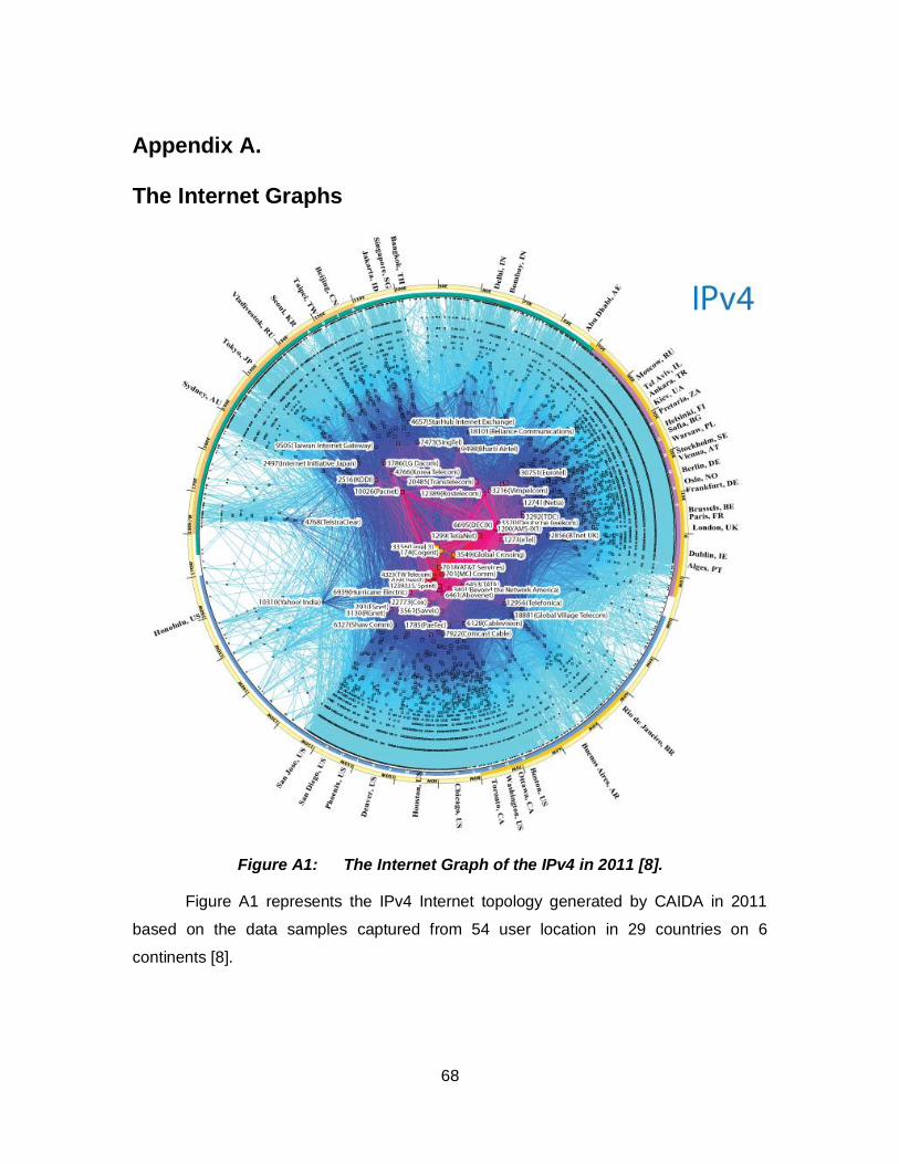
68
Appendix A. The Internet Graphs
Figure A1: The Internet Graph of the IPv4 in 2011 [8].
Figure A1 represents the IPv4 Internet topology generated by CAIDA in 2011
based on the data samples captured from 54 user location in 29 countries on 6
continents [8].
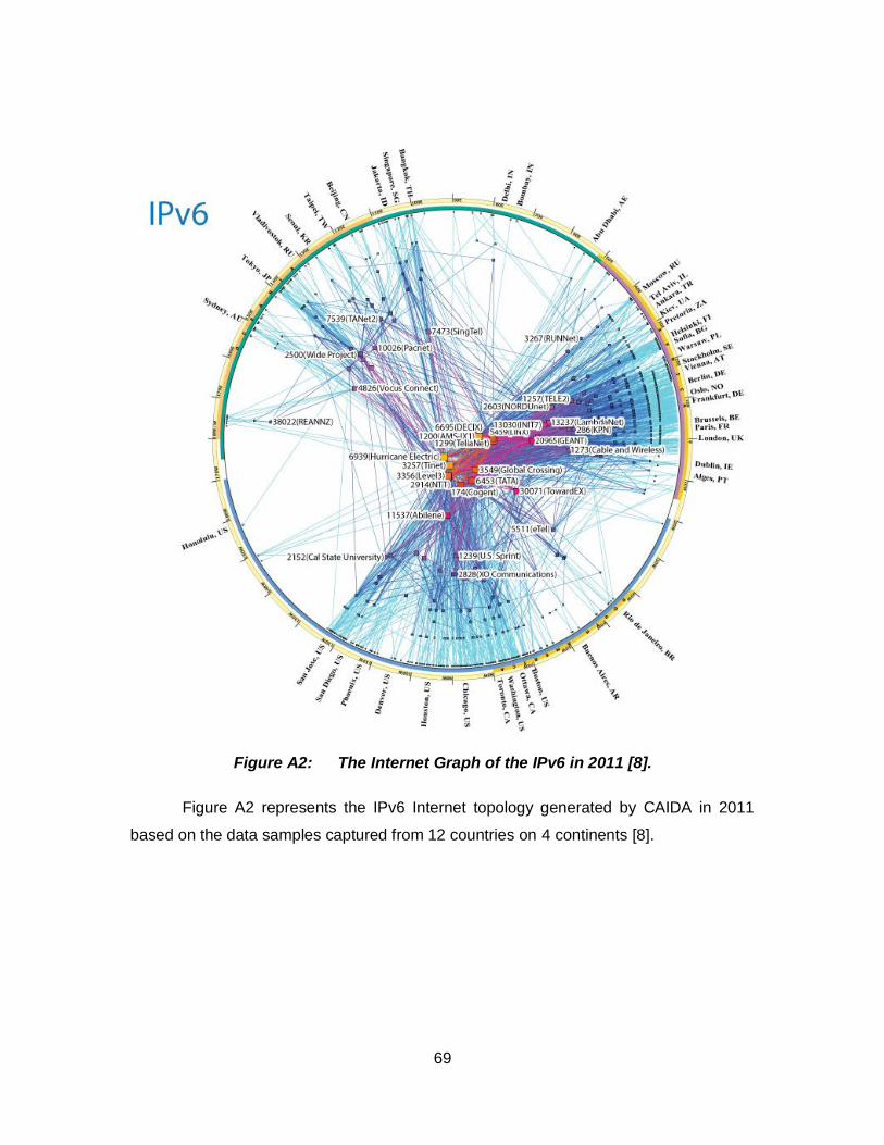
69
Figure A2: The Internet Graph of the IPv6 in 2011 [8].
Figure A2 represents the IPv6 Internet topology generated by CAIDA in 2011
based on the data samples captured from 12 countries on 4 continents [8].
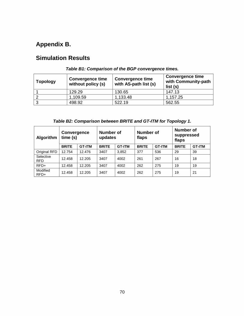
70
Appendix B. Simulation Results
Table B1: Comparison of the BGP convergence times.
Topology Convergence time without policy (s)
Convergence time with AS-path list (s)
Convergence time with Community-path list (s)
1 129.29 130.65 147.13
2 1,109.59 1,133.48 1,157.25
3 498.92 522.19 562.55
Table B2: Comparison between BRITE and GT-ITM for Topology 1.
Algorithm Convergence time (s)
Number of updates
Number of flaps
Number of suppressed flaps
BRITE GT-ITM BRITE GT-ITM BRITE GT-ITM BRITE GT-ITM
Original RFD 12.754 12.476 3407 3,852 377 536 29 39
Selective RFD
12.458 12.205 3407 4002 261 267 16 18
RFD+ 12.458 12.205 3407 4002 262 275 19 19
Modified RFD+
12.458 12.205 3407 4002 262 275 19 21
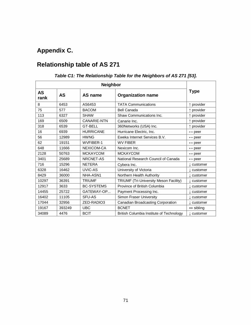
71
Appendix C. Relationship table of AS 271
Table C1: The Relationship Table for the Neighbors of AS 271 [53].
Neighbor
Type AS rank
AS AS name Organization name
8 6453 AS6453 TATA Communications ↑ provider
75 577 BACOM Bell Canada ↑ provider
113 6327 SHAW Shaw Communications Inc. ↑ provider
169 6509 CANARIE-NTN Canarie Inc. ↑ provider
318 6539 GT-BELL 360Networks (USA) Inc. ↑ provider
16 6939 HURRICANE Hurricane Electric, Inc. ↔ peer
56 12989 HWNG Eweka Internet Services B.V. ↔ peer
62 19151 WVFIBER-1 WV FIBER ↔ peer
648 11666 NEXICOM-CA Nexicom Inc. ↔ peer
2128 50763 MCKAYCOM MCKAYCOM ↔ peer
3401 25689 NRCNET-AS National Research Council of Canada ↔ peer
716 15296 NETERA Cybera Inc. ↓ customer
6328 16462 UVIC-AS University of Victoria ↓ customer
8429 36000 NHA-ASN1 Northern Health Authority ↓ customer
10297 36391 TRIUMF TRIUMF (Tri-University Meson Facility) ↓ customer
12917 3633 BC-SYSTEMS Province of British Columbia ↓ customer
14455 25722 GATEWAY-OP... Payment Processing Inc. ↓ customer
16402 11105 SFU-AS Simon Fraser University ↓ customer
17044 32956 ZED-RADIO3 Canadian Broadcasting Corporation ↓ customer
19167 393249 UBC BCNET ⇔ sibling
34089 4476 BCIT British Columbia Institute of Technology ↓ customer
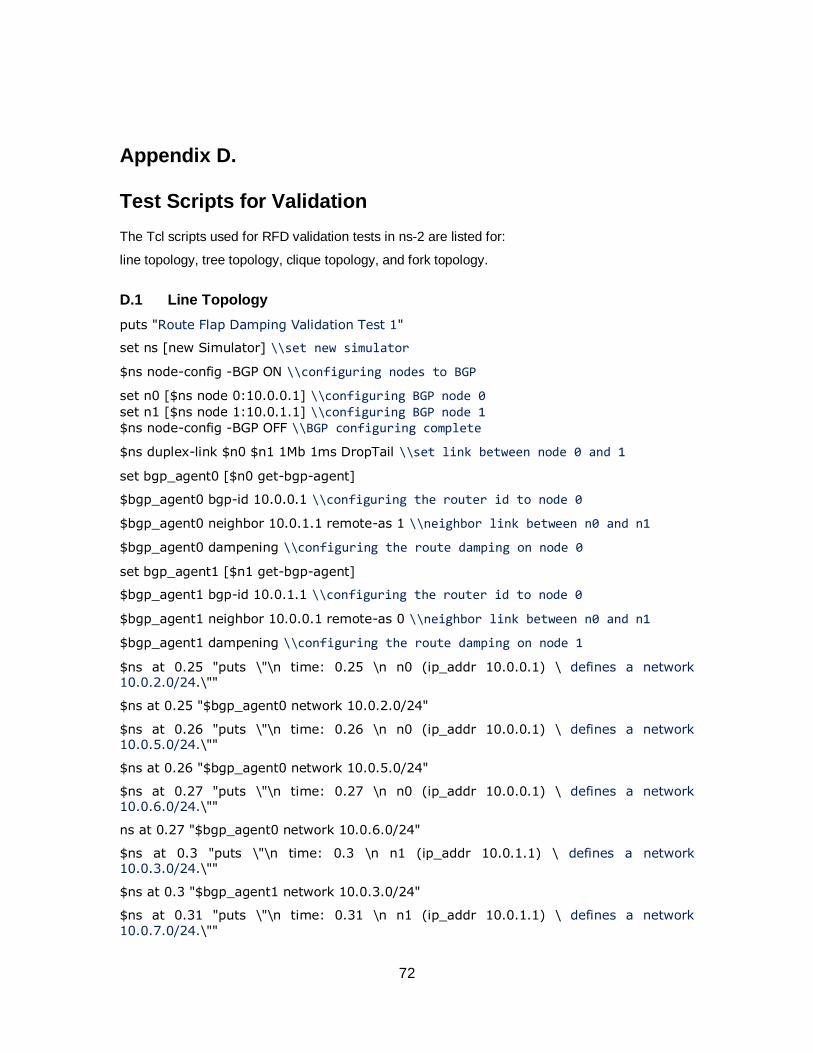
72
Appendix D. Test Scripts for Validation
The Tcl scripts used for RFD validation tests in ns-2 are listed for:
line topology, tree topology, clique topology, and fork topology.
D.1 Line Topology
puts "Route Flap Damping Validation Test 1"
set ns [new Simulator] \\set new simulator
$ns node-config -BGP ON \\configuring nodes to BGP
set n0 [$ns node 0:10.0.0.1] \\configuring BGP node 0 set n1 [$ns node 1:10.0.1.1] \\configuring BGP node 1 $ns node-config -BGP OFF \\BGP configuring complete
$ns duplex-link $n0 $n1 1Mb 1ms DropTail \\set link between node 0 and 1
set bgp_agent0 [$n0 get-bgp-agent]
$bgp_agent0 bgp-id 10.0.0.1 \\configuring the router id to node 0
$bgp_agent0 neighbor 10.0.1.1 remote-as 1 \\neighbor link between n0 and n1
$bgp_agent0 dampening \\configuring the route damping on node 0
set bgp_agent1 [$n1 get-bgp-agent]
$bgp_agent1 bgp-id 10.0.1.1 \\configuring the router id to node 0
$bgp_agent1 neighbor 10.0.0.1 remote-as 0 \\neighbor link between n0 and n1
$bgp_agent1 dampening \\configuring the route damping on node 1
$ns at 0.25 "puts \"\n time: 0.25 \n n0 (ip_addr 10.0.0.1) \ defines a network 10.0.2.0/24.\""
$ns at 0.25 "$bgp_agent0 network 10.0.2.0/24"
$ns at 0.26 "puts \"\n time: 0.26 \n n0 (ip_addr 10.0.0.1) \ defines a network 10.0.5.0/24.\""
$ns at 0.26 "$bgp_agent0 network 10.0.5.0/24"
$ns at 0.27 "puts \"\n time: 0.27 \n n0 (ip_addr 10.0.0.1) \ defines a network 10.0.6.0/24.\""
ns at 0.27 "$bgp_agent0 network 10.0.6.0/24"
$ns at 0.3 "puts \"\n time: 0.3 \n n1 (ip_addr 10.0.1.1) \ defines a network 10.0.3.0/24.\""
$ns at 0.3 "$bgp_agent1 network 10.0.3.0/24"
$ns at 0.31 "puts \"\n time: 0.31 \n n1 (ip_addr 10.0.1.1) \ defines a network
10.0.7.0/24.\""
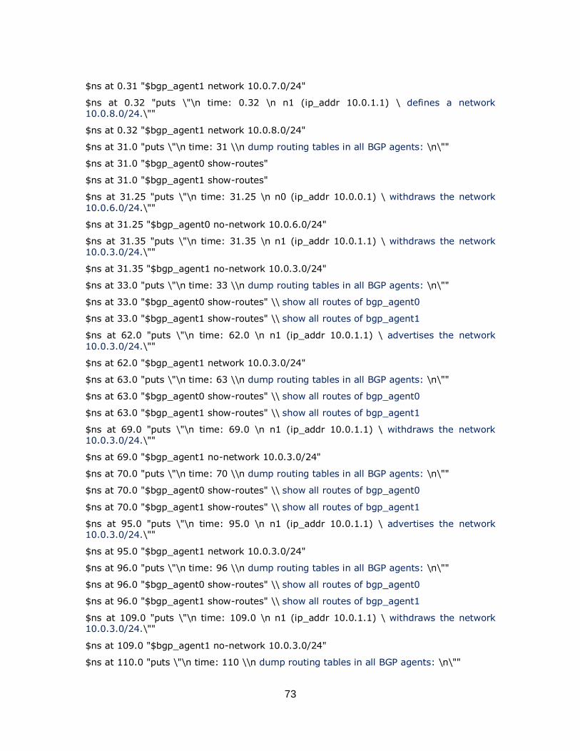
73
$ns at 0.31 "$bgp_agent1 network 10.0.7.0/24"
$ns at 0.32 "puts \"\n time: 0.32 \n n1 (ip_addr 10.0.1.1) \ defines a network 10.0.8.0/24.\""
$ns at 0.32 "$bgp_agent1 network 10.0.8.0/24"
$ns at 31.0 "puts \"\n time: 31 \\n dump routing tables in all BGP agents: \n\""
$ns at 31.0 "$bgp_agent0 show-routes"
$ns at 31.0 "$bgp_agent1 show-routes"
$ns at 31.25 "puts \"\n time: 31.25 \n n0 (ip_addr 10.0.0.1) \ withdraws the network
10.0.6.0/24.\""
$ns at 31.25 "$bgp_agent0 no-network 10.0.6.0/24"
$ns at 31.35 "puts \"\n time: 31.35 \n n1 (ip_addr 10.0.1.1) \ withdraws the network 10.0.3.0/24.\""
$ns at 31.35 "$bgp_agent1 no-network 10.0.3.0/24"
$ns at 33.0 "puts \"\n time: 33 \\n dump routing tables in all BGP agents: \n\""
$ns at 33.0 "$bgp_agent0 show-routes" \\ show all routes of bgp_agent0
$ns at 33.0 "$bgp_agent1 show-routes" \\ show all routes of bgp_agent1
$ns at 62.0 "puts \"\n time: 62.0 \n n1 (ip_addr 10.0.1.1) \ advertises the network
10.0.3.0/24.\""
$ns at 62.0 "$bgp_agent1 network 10.0.3.0/24"
$ns at 63.0 "puts \"\n time: 63 \\n dump routing tables in all BGP agents: \n\""
$ns at 63.0 "$bgp_agent0 show-routes" \\ show all routes of bgp_agent0
$ns at 63.0 "$bgp_agent1 show-routes" \\ show all routes of bgp_agent1
$ns at 69.0 "puts \"\n time: 69.0 \n n1 (ip_addr 10.0.1.1) \ withdraws the network 10.0.3.0/24.\""
$ns at 69.0 "$bgp_agent1 no-network 10.0.3.0/24"
$ns at 70.0 "puts \"\n time: 70 \\n dump routing tables in all BGP agents: \n\""
$ns at 70.0 "$bgp_agent0 show-routes" \\ show all routes of bgp_agent0
$ns at 70.0 "$bgp_agent1 show-routes" \\ show all routes of bgp_agent1
$ns at 95.0 "puts \"\n time: 95.0 \n n1 (ip_addr 10.0.1.1) \ advertises the network 10.0.3.0/24.\""
$ns at 95.0 "$bgp_agent1 network 10.0.3.0/24"
$ns at 96.0 "puts \"\n time: 96 \\n dump routing tables in all BGP agents: \n\""
$ns at 96.0 "$bgp_agent0 show-routes" \\ show all routes of bgp_agent0
$ns at 96.0 "$bgp_agent1 show-routes" \\ show all routes of bgp_agent1
$ns at 109.0 "puts \"\n time: 109.0 \n n1 (ip_addr 10.0.1.1) \ withdraws the network 10.0.3.0/24.\""
$ns at 109.0 "$bgp_agent1 no-network 10.0.3.0/24"
$ns at 110.0 "puts \"\n time: 110 \\n dump routing tables in all BGP agents: \n\""
74
$ns at 110.0 "$bgp_agent0 show-routes" \\ show all routes of bgp_agent0
$ns at 110.0 "$bgp_agent1 show-routes" \\ show all routes of bgp_agent1
$ns at 126.0 "puts \"\n time: 126.0 \n n1 (ip_addr 10.0.1.1) \ advertises the network 10.0.3.0/24.\""
$ns at 126.0 "$bgp_agent1 network 10.0.3.0/24"
$ns at 127.0 "puts \"\n time: 127 \\n dump routing tables in all BGP agents: \n\""
$ns at 127.0 "$bgp_agent0 show-routes" \\ show all routes of bgp_agent0
$ns at 127.0 "$bgp_agent1 show-routes" \\ show all routes of bgp_agent1
$ns at 137.0 "puts \"\n time: 137.0 \n n1 (ip_addr 10.0.1.1) \ withdraws the network 10.0.3.0/24.\""
$ns at 137.0 "$bgp_agent1 no-network 10.0.3.0/24"
$ns at 158.0 "puts \"\n time: 158.0 \n n1 (ip_addr 10.0.1.1) \ advertises the network 10.0.3.0/24.\""
$ns at 158.0 "$bgp_agent1 network 10.0.3.0/24"
$ns at 160.0 "puts \"\n time: 160 \\n dump routing tables in all BGP agents: \n\""
$ns at 160.0 "$bgp_agent0 show-routes" \\ show all routes of bgp_agent0
$ns at 160.0 "$bgp_agent0 show-all" \\ show all messages of bgp_agent0
$ns at 160.0 "$bgp_agent1 show-routes" \\ show all routes of bgp_agent1
$ns at 160.0 "$bgp_agent1 show-all" \\ show all messages of bgp_agent1
$ns at 1500.0 "puts \"\n time: 1500 \\n dump routing tables in all BGP agents: \n\""
$ns at 1500.0 "$bgp_agent0 show-routes" \\ show all routes of bgp_agent0
$ns at 1500.0 "$bgp_agent0 show-all" \\ show all messages of bgp_agent0
$ns at 1500.0 "$bgp_agent1 show-routes" \\ show all routes of bgp_agent1
$ns at 1500.0 "$bgp_agent1 show-all" \\ show all messages of bgp_agent1
$ns at 3000.0 "puts \"\n time: 3000 \
\n dump routing tables in all BGP agents: \n\""
$ns at 3000.0 "$bgp_agent0 show-routes" \\ Show routes of bgp_agent0
$ns at 3000.0 "$bgp_agent0 show-all" \\ Show all messages of bgp_agent0
$ns at 3000.0 "$bgp_agent0 show-damping" \\ Show damping routes of bgp_agent0
$ns at 3000.0 "$bgp_agent1 show-routes" \\ Show routes of bgp_agent1
$ns at 3000.0 "$bgp_agent1 show-all" \\ Show all messages of bgp_agent1
$ns at 3000.0 "$bgp_agent1 show-damping" \\ Show damping routes of bgp_agent1
$ns at 3100.0 "finish" \\ Simulation finishes
proc finish {} {
global ns
puts "Simulation finished. "
75
exit 0
}
puts "Simulation starts..."
$ns run \\ Simulation starts
D.2 Tree Topology
puts "Route Flap Damping Validation Test 2"
set ns [new Simulator] \\ set new simulator
$ns node-config -BGP ON \\ configuring nodes to BGP
set n0 [$ns node 0:10.0.0.4] \\ configuring BGP node 0
set n1 [$ns node 1:10.0.1.3] \\ configuring BGP node 1
set n2 [$ns node 2:10.0.2.2] \\ configuring BGP node 2
set n3 [$ns node 3:10.0.3.1] \\ configuring BGP node 3
$ns node-config -BGP OFF \\ configuring BGP node 0
$ns duplex-link $n0 $n1 1Mb 1ms DropTail \\ set link between node 0 and 1
$ns duplex-link $n2 $n0 1Mb 1ms DropTail \\ set link between node 0 and 2
$ns duplex-link $n0 $n3 1Mb 1ms DropTail \\ set link between node 0 and 2
set bgp_agent0 [$n0 get-bgp-agent]
$bgp_agent0 bgp-id 10.0.0.4 \\ configuring the router id to node 0
$bgp_agent0 neighbor 10.0.1.3 remote-as 1 \\ configuring neighbors of node 0
$bgp_agent0 neighbor 10.0.2.2 remote-as 2 \\ configuring neighbors of node 0
$bgp_agent0 neighbor 10.0.3.1 remote-as 3 \\ configuring neighbors of node 0
$bgp_agent0 dampening 0 0 3000 750 900 1000 500 3600 \\ configuring damping parameters for node 0
set bgp_agent1 [$n1 get-bgp-agent]
$bgp_agent1 bgp-id 10.0.1.3 \\ configuring the router id to node 1
$bgp_agent1 neighbor 10.0.0.4 remote-as 0 \\ configuring neighbors of node 1
$bgp_agent1 dampening 0 0 3000 750 900 1000 500 3600 \\ configuring damping parameters for node 1
set bgp_agent2 [$n2 get-bgp-agent]
$bgp_agent2 bgp-id 10.0.2.2 \\ configuring the router id to node 2
$bgp_agent2 neighbor 10.0.0.4 remote-as 0 \\ configuring neighbors of node 2
$bgp_agent2 dampening 0 0 3000 750 900 1000 500 3600 \\ configuring damping parameters for node 1
set bgp_agent3 [$n3 get-bgp-agent]
$bgp_agent3 bgp-id 10.0.3.1 \\ configuring the router id to node 3
76
$bgp_agent3 neighbor 10.0.0.4 remote-as 0 \\ configuring neighbors of node 3
$bgp_agent3 dampening 0 0 3000 750 900 1000 500 3600 \\ configuring damping parameters for node 3
$ns at 0.2 "puts \"\n time: 0.2 \n n0 (ip_addr 10.0.0.4) \ defines a network 10.0.4.0/24.\""
$ns at 0.2 "$bgp_agent0 network 10.0.4.0/24"
$ns at 2.22 "puts \"\n time: 2.22 \n n0 (ip_addr 10.0.0.4) \ defines a network 10.0.5.0/24.\""
$ns at 2.22 "$bgp_agent0 network 10.0.5.0/24"
$ns at 2.57 "puts \"\n time: 2.57 \n n0 (ip_addr 10.0.0.4) \ defines a network 10.0.6.0/24.\""
$ns at 2.57 "$bgp_agent0 network 10.0.6.0/24"
$ns at 3.3 "puts \"\n time: 3.3 \n n1 (ip_addr 10.0.1.3) \ defines a network 10.0.7.0/24.\""
$ns at 3.3 "$bgp_agent1 network 10.0.7.0/24"
$ns at 4.31 "puts \"\n time: 4.31 \n n1 (ip_addr 10.0.1.3) \ defines a network 10.0.8.0/24.\""
$ns at 4.31 "$bgp_agent1 network 10.0.8.0/24"
$ns at 5.32 "puts \"\n time: 5.32 \n n1 (ip_addr 10.0.1.3) \ defines a network 10.0.9.0/24.\""
$ns at 5.32 "$bgp_agent1 network 10.0.9.0/24"
$ns at 6.35 "puts \"\n time: 6.35 \n n2 (ip_addr 10.0.2.2) \ defines a network 10.1.7.0/24.\""
$ns at 6.35 "$bgp_agent2 network 10.1.7.0/24"
$ns at 7.37 "puts \"\n time: 7.37 \n n2 (ip_addr 10.0.2.2) \ defines a network 10.1.8.0/24.\""
$ns at 7.37 "$bgp_agent2 network 10.1.8.0/24"
$ns at 62.0 "puts \"\n time: 62 \\n dump routing tables in all BGP agents: \n\""
$ns at 62.0 "$bgp_agent0 show-routes" \\ Show routes of bgp_agent0
$ns at 62.0 "$bgp_agent0 show-all" \\ Show all messages of bgp_agent0
$ns at 62.0 "$bgp_agent1 show-routes" Show routes of bgp_agent1
$ns at 62.0 "$bgp_agent1 show-all" \\ Show all messages of bgp_agent1
$ns at 62.0 "$bgp_agent2 show-routes" \\ Show routes of bgp_agent2
$ns at 62.0 "$bgp_agent2 show-all" \\ Show all messages of bgp_agent2
$ns at 62.0 "$bgp_agent3 show-routes" \\ Show routes of bgp_agent3
$ns at 62.0 "$bgp_agent3 show-all" \\ Show all messages of bgp_agent3
$ns at 62.05 "puts \"\n time: 62.05 \n n2 (ip_addr 10.0.2.2) \ withdraws the network 10.1.7.0/24.\""
$ns at 62.05 "$bgp_agent2 no-network 10.1.7.0/24"
77
$ns at 62.85 "puts \"\n time: 62.85 \n n1 (ip_addr 10.0.1.3) \ withdraws the network 10.0.7.0/24.\""
$ns at 62.85 "$bgp_agent1 no-network 10.0.7.0/24"
$ns at 66.0 "puts \"\n time: 66 \\n dump routing tables in all BGP agents: \n\""
$ns at 66.0 "$bgp_agent0 show-routes" \\ Show routes of bgp_agent0
$ns at 66.0 "$bgp_agent0 show-all" Show all messages of bgp_agent0
$ns at 66.0 "$bgp_agent1 show-routes" \\ Show routes of bgp_agent1
$ns at 66.0 "$bgp_agent1 show-all" Show all messages of bgp_agent1
$ns at 66.0 "$bgp_agent2 show-routes" \\ Show routes of bgp_agent2
$ns at 66.0 "$bgp_agent2 show-all" Show all messages of bgp_agent2
$ns at 66.0 "$bgp_agent3 show-routes" \\ Show routes of bgp_agent3
$ns at 66.0 "$bgp_agent3 show-all" Show all messages of bgp_agent3
$ns at 95.0 "puts \"\n time: 95.0 \n n1 (ip_addr 10.0.1.3) \ advertises the network 10.0.7.0/24.\""
$ns at 95.0 "$bgp_agent1 network 10.0.7.0/24"
$ns at 100.0 "puts \"\n time: 100 \\n dump routing tables in all BGP agents: \n\""
$ns at 100.0 "$bgp_agent0 show-routes" \\ Show routes of bgp_agent0
$ns at 100.0 "$bgp_agent0 show-all" \\ Show all messages of bgp_agent0
$ns at 100.0 "$bgp_agent1 show-routes" \\ Show routes of bgp_agent1
$ns at 100.0 "$bgp_agent1 show-all" \\ Show all messages of bgp_agent1
$ns at 100.0 "$bgp_agent2 show-routes" \\ Show routes of bgp_agent2
$ns at 100.0 "$bgp_agent2 show-all" \\ Show all messages of bgp_agent2
$ns at 100.0 "$bgp_agent3 show-routes" \\ Show routes of bgp_agent3
$ns at 100.0 "$bgp_agent3 show-all" \\ Show all messages of bgp_agent3
$ns at 200.0 "puts \"\n time: 200.0 \n n1 (ip_addr 10.0.1.3) \ advertises the network 10.0.7.0/24.\""
$ns at 200.0 "$bgp_agent1 network 10.0.7.0/24"
$ns at 210.0 "puts \"\n time: 210 \\n dump routing tables in all BGP agents: \n\""
$ns at 210.0 "$bgp_agent0 show-routes" \\ Show routes of bgp_agent0
$ns at 210.0 "$bgp_agent0 show-all" \\ Show all messages of bgp_agent0
$ns at 210.0 "$bgp_agent0 show-damping" \\ Show damping of bgp_agent0
$ns at 210.0 "$bgp_agent1 show-routes" \\ Show routes of bgp_agent1
$ns at 210.0 "$bgp_agent1 show-all" \\ Show all messages of bgp_agent1
$ns at 210.0 "$bgp_agent1 show-damping" \\ Show damping of bgp_agent1
$ns at 210.0 "$bgp_agent2 show-routes" \\ Show routes of bgp_agent2
$ns at 210.0 "$bgp_agent2 show-all" \\ Show all messages of bgp_agent2
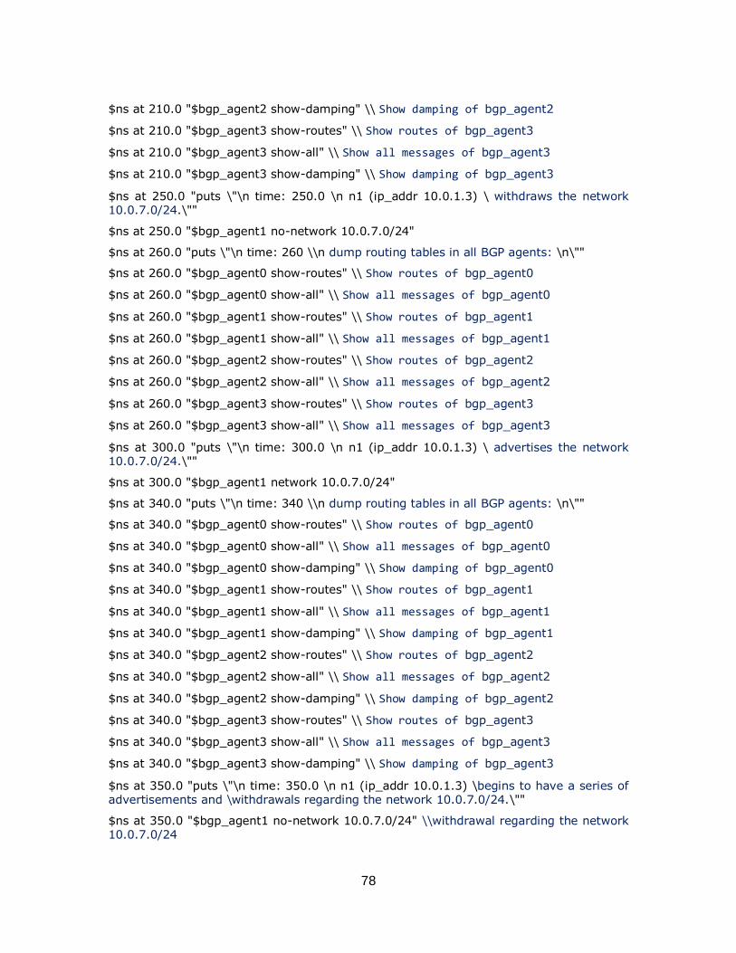
78
$ns at 210.0 "$bgp_agent2 show-damping" \\ Show damping of bgp_agent2
$ns at 210.0 "$bgp_agent3 show-routes" \\ Show routes of bgp_agent3
$ns at 210.0 "$bgp_agent3 show-all" \\ Show all messages of bgp_agent3
$ns at 210.0 "$bgp_agent3 show-damping" \\ Show damping of bgp_agent3
$ns at 250.0 "puts \"\n time: 250.0 \n n1 (ip_addr 10.0.1.3) \ withdraws the network 10.0.7.0/24.\""
$ns at 250.0 "$bgp_agent1 no-network 10.0.7.0/24"
$ns at 260.0 "puts \"\n time: 260 \\n dump routing tables in all BGP agents: \n\""
$ns at 260.0 "$bgp_agent0 show-routes" \\ Show routes of bgp_agent0
$ns at 260.0 "$bgp_agent0 show-all" \\ Show all messages of bgp_agent0
$ns at 260.0 "$bgp_agent1 show-routes" \\ Show routes of bgp_agent1
$ns at 260.0 "$bgp_agent1 show-all" \\ Show all messages of bgp_agent1
$ns at 260.0 "$bgp_agent2 show-routes" \\ Show routes of bgp_agent2
$ns at 260.0 "$bgp_agent2 show-all" \\ Show all messages of bgp_agent2
$ns at 260.0 "$bgp_agent3 show-routes" \\ Show routes of bgp_agent3
$ns at 260.0 "$bgp_agent3 show-all" \\ Show all messages of bgp_agent3
$ns at 300.0 "puts \"\n time: 300.0 \n n1 (ip_addr 10.0.1.3) \ advertises the network 10.0.7.0/24.\""
$ns at 300.0 "$bgp_agent1 network 10.0.7.0/24"
$ns at 340.0 "puts \"\n time: 340 \\n dump routing tables in all BGP agents: \n\""
$ns at 340.0 "$bgp_agent0 show-routes" \\ Show routes of bgp_agent0
$ns at 340.0 "$bgp_agent0 show-all" \\ Show all messages of bgp_agent0
$ns at 340.0 "$bgp_agent0 show-damping" \\ Show damping of bgp_agent0
$ns at 340.0 "$bgp_agent1 show-routes" \\ Show routes of bgp_agent1
$ns at 340.0 "$bgp_agent1 show-all" \\ Show all messages of bgp_agent1
$ns at 340.0 "$bgp_agent1 show-damping" \\ Show damping of bgp_agent1
$ns at 340.0 "$bgp_agent2 show-routes" \\ Show routes of bgp_agent2
$ns at 340.0 "$bgp_agent2 show-all" \\ Show all messages of bgp_agent2
$ns at 340.0 "$bgp_agent2 show-damping" \\ Show damping of bgp_agent2
$ns at 340.0 "$bgp_agent3 show-routes" \\ Show routes of bgp_agent3
$ns at 340.0 "$bgp_agent3 show-all" \\ Show all messages of bgp_agent3
$ns at 340.0 "$bgp_agent3 show-damping" \\ Show damping of bgp_agent3
$ns at 350.0 "puts \"\n time: 350.0 \n n1 (ip_addr 10.0.1.3) \begins to have a series of advertisements and \withdrawals regarding the network 10.0.7.0/24.\""
$ns at 350.0 "$bgp_agent1 no-network 10.0.7.0/24" \\withdrawal regarding the network 10.0.7.0/24
79
$ns at 400.0 "$bgp_agent1 network 10.0.7.0/24" \\ advertisement regarding the network 10.0.7.0/24
$ns at 450.0 "$bgp_agent1 no-network 10.0.7.0/24" \\withdrawal regarding the network 10.0.7.0/24
$ns at 500.0 "$bgp_agent1 network 10.0.7.0/24" \\ advertisement regarding the network 10.0.7.0/24
$ns at 550.0 "$bgp_agent1 no-network 10.0.7.0/24" \\withdrawal regarding the network 10.0.7.0/24
$ns at 600.0 "$bgp_agent1 network 10.0.7.0/24" \\ advertisement regarding the network 10.0.7.0/24
$ns at 650.0 "$bgp_agent1 no-network 10.0.7.0/24" \\withdrawal regarding the network 10.0.7.0/24
$ns at 700.0 "$bgp_agent1 network 10.0.7.0/24" \\ advertisement regarding the network 10.0.7.0/24
$ns at 750.0 "$bgp_agent1 no-network 10.0.7.0/24" \\withdrawal regarding the network 10.0.7.0/24
$ns at 800.0 "$bgp_agent1 network 10.0.7.0/24" \\advertisement regarding the network
10.0.7.0/24
$ns at 850.0 "puts \"\n time: 850 \\n dump routing tables in all BGP agents: \n\""
$ns at 850.0 "$bgp_agent0 show-routes" \\ Show routes of bgp_agent0
$ns at 850.0 "$bgp_agent0 show-all" \\ Show all messages of bgp_agent0
$ns at 850.0 "$bgp_agent0 show-damping" \\ Show damping of bgp_agent0
$ns at 850.0 "$bgp_agent1 show-routes" \\ Show routes of bgp_agent1
$ns at 850.0 "$bgp_agent1 show-all" \\ Show all messages of bgp_agent1
$ns at 850.0 "$bgp_agent1 show-damping" \\ Show damping of bgp_agent1
$ns at 850.0 "$bgp_agent2 show-routes" \\ Show routes of bgp_agent2
$ns at 850.0 "$bgp_agent2 show-all" \\ Show all messages of bgp_agent2
$ns at 850.0 "$bgp_agent2 show-damping" \\ Show damping of bgp_agent2
$ns at 850.0 "$bgp_agent3 show-routes" \\ Show routes of bgp_agent3
$ns at 850.0 "$bgp_agent3 show-all" \\ Show all messages of bgp_agent3
$ns at 850.0 "$bgp_agent3 show-damping" \\ Show damping of bgp_agent3
$ns at 1200.0 "puts \"\n time: 1200.0 \n n2 (ip_addr 10.0.2.2) \begins to have a series of advertisements and \withdrawals regarding the network 10.1.7.0/24.\""
$ns at 1200.0 "$bgp_agent2 network 10.1.7.0/24" \\advertisement regarding the network 10.0.7.0/24
$ns at 1300.0 "$bgp_agent2 no-network 10.1.7.0/24" \\withdrawal regarding the network 10.0.7.0/24
$ns at 1400.0 "$bgp_agent2 network 10.1.7.0/24" \\advertisement regarding the
network 10.0.7.0/24
80
$ns at 1500.0 "$bgp_agent2 no-network 10.1.7.0/24" \\withdrawal regarding the network 10.0.7.0/24
$ns at 1600.0 "$bgp_agent2 network 10.1.7.0/24" \\advertisement regarding the network 10.0.7.0/24
$ns at 1700.0 "$bgp_agent2 no-network 10.1.7.0/24" \\withdrawal regarding the network 10.0.7.0/24
$ns at 1800.0 "$bgp_agent2 network 10.1.7.0/24" \\advertisement regarding the network 10.0.7.0/24
$ns at 1900.0 "$bgp_agent2 no-network 10.1.7.0/24" \\withdrawal regarding the network 10.0.7.0/24
$ns at 2000.0 "$bgp_agent2 network 10.1.7.0/24" \\advertisement regarding the network 10.0.7.0/24
$ns at 2005.0 "puts \"\n time: 2005 \\n dump routing tables in all BGP agents: \n\""
$ns at 2005.0 "$bgp_agent0 show-routes" \\ Show routes of bgp_agent0
$ns at 2005.0 "$bgp_agent0 show-all" \\ Show all messages of bgp_agent0
$ns at 2005.0 "$bgp_agent0 show-damping" \\ Show damping of bgp_agent0
$ns at 2005.0 "$bgp_agent1 show-routes" \\ Show routes of bgp_agent1
$ns at 2005.0 "$bgp_agent1 show-all" \\ Show all messages of bgp_agent1
$ns at 2005.0 "$bgp_agent1 show-damping" \\ Show damping of bgp_agent1
$ns at 2005.0 "$bgp_agent2 show-routes" \\ Show routes of bgp_agent2
$ns at 2005.0 "$bgp_agent2 show-all" \\ Show all messages of bgp_agent2
$ns at 2005.0 "$bgp_agent2 show-damping" \\ Show damping of bgp_agent2
$ns at 2005.0 "$bgp_agent3 show-routes" \\ Show routes of bgp_agent3
$ns at 2005.0 "$bgp_agent3 show-all" \\ Show all messages of bgp_agent3
$ns at 2005.0 "$bgp_agent3 show-damping" \\ Show damping of bgp_agent3
$ns at 3500.0 "puts \"\n time: 3500 \\n dump routing tables in all BGP agents: \n\""
$ns at 3500.0 "$bgp_agent0 show-routes" \\ Show routes of bgp_agent0
$ns at 3500.0 "$bgp_agent0 show-all" \\ Show all messages of bgp_agent0
$ns at 3500.0 "$bgp_agent0 show-damping" \\ Show damping of bgp_agent0
$ns at 3500.0 "$bgp_agent1 show-routes" \\ Show routes of bgp_agent1
$ns at 3500.0 "$bgp_agent1 show-all" \\ Show all messages of bgp_agent1
$ns at 3500.0 "$bgp_agent1 show-damping" \\ Show damping of bgp_agent1
$ns at 3500.0 "$bgp_agent2 show-routes" \\ Show routes of bgp_agent2
$ns at 3500.0 "$bgp_agent2 show-all" \\ Show all messages of bgp_agent2
$ns at 3500.0 "$bgp_agent2 show-damping" \\ Show damping of bgp_agent2
$ns at 3500.0 "$bgp_agent3 show-routes" \\ Show routes of bgp_agent3
$ns at 3500.0 "$bgp_agent3 show-all" \\ Show all messages of bgp_agent3
81
$ns at 3500.0 "$bgp_agent3 show-damping" \\ Show damping of bgp_agent3
$ns at 3530.0 "puts \"\n time: 3530.0 \n n1 (ip_addr 10.0.1.3) \ advertises the network 10.0.7.0/24.\""
$ns at 3530.0 "$bgp_agent1 network 10.0.7.0/24"
$ns at 3535.0 "puts \"\n time: 3535.0 \n n2 (ip_addr 10.0.2.2) \ advertises the network 10.1.7.0/24.\""
$ns at 3535.0 "$bgp_agent2 network 10.1.7.0/24"
$ns at 3550.0 "puts \"\n time: 3550 \\n dump routing tables in all BGP agents: \n\""
$ns at 3550.0 "$bgp_agent0 show-routes" \\ Show routes of bgp_agent0
$ns at 3550.0 "$bgp_agent0 show-all" \\ Show all messages of bgp_agent0
$ns at 3550.0 "$bgp_agent1 show-routes" \\ Show routes of bgp_agent1
$ns at 3550.0 "$bgp_agent1 show-all" \\ Show all messages of bgp_agent1
$ns at 3550.0 "$bgp_agent2 show-routes" \\ Show routes of bgp_agent2
$ns at 3550.0 "$bgp_agent2 show-all" \\ Show all messages of bgp_agent2
$ns at 3550.0 "$bgp_agent3 show-routes" \\ Show routes of bgp_agent3
$ns at 3550.0 "$bgp_agent3 show-all" \\ Show all messages of bgp_agent3
$ns at 3580.0 "puts \"\n time: 3580.0 \n n1 (ip_addr 10.0.1.3) \withdraws the network 10.0.7.0/24.\""
$ns at 3580.0 "$bgp_agent1 no-network 10.0.7.0/24"
$ns at 3600.0 "puts \"\n time: 3600 \\n dump routing tables in all BGP agents: \n\""
$ns at 3600.0 "$bgp_agent0 show-routes" \\ Show routes of bgp_agent0
$ns at 3600.0 "$bgp_agent0 show-all" \\ Show all messages of bgp_agent0
$ns at 3600.0 "$bgp_agent1 show-routes" \\ Show routes of bgp_agent1
$ns at 3600.0 "$bgp_agent1 show-all" \\ Show all messages of bgp_agent1
$ns at 3600.0 "$bgp_agent2 show-routes" \\ Show routes of bgp_agent2
$ns at 3600.0 "$bgp_agent2 show-all" \\ Show all messages of bgp_agent2
$ns at 3600.0 "$bgp_agent3 show-routes" \\ Show routes of bgp_agent3
$ns at 3600.0 "$bgp_agent3 show-all" \\ Show all messages of bgp_agent3
$ns at 3650.0 "puts \"\n time: 3650.0 \n n1 (ip_addr 10.0.1.3) \ advertises the network 10.0.7.0/24.\""
$ns at 3650.0 "$bgp_agent1 network 10.0.7.0/24"
$ns at 3700.0 "puts \"\n time: 3700 \\n dump routing tables in all BGP agents: \n\""
$ns at 3700.0 "$bgp_agent0 show-routes" \\ Show routes of bgp_agent0
$ns at 3700.0 "$bgp_agent0 show-all" \\ Show all messages of bgp_agent0
$ns at 3700.0 "$bgp_agent1 show-routes" \\ Show routes of bgp_agent1
$ns at 3700.0 "$bgp_agent1 show-all" \\ Show all messages of bgp_agent1
82
$ns at 3700.0 "$bgp_agent2 show-routes" \\ Show routes of bgp_agent2
$ns at 3700.0 "$bgp_agent2 show-all" \\ Show all messages of bgp_agent2
$ns at 3700.0 "$bgp_agent3 show-routes" \\ Show routes of bgp_agent3
$ns at 3700.0 "$bgp_agent3 show-all" \\ Show all messages of bgp_agent3
$ns at 3750.0 "puts \"\n time: 3750.0 \n n1 (ip_addr 10.0.1.3) \ withdraws the network 10.0.7.0/24.\""
$ns at 3750.0 "$bgp_agent1 no-network 10.0.7.0/24"
$ns at 3800.0 "puts \"\n time: 3800 \\n dump routing tables in all BGP agents: \n\""
$ns at 3800.0 "$bgp_agent0 show-routes" \\ Show routes of bgp_agent0
$ns at 3800.0 "$bgp_agent0 show-all" \\ Show all messages of bgp_agent0
$ns at 3800.0 "$bgp_agent1 show-routes" \\ Show routes of bgp_agent1
$ns at 3800.0 "$bgp_agent1 show-all" \\ Show all messages of bgp_agent1
$ns at 3800.0 "$bgp_agent2 show-routes" \\ Show routes of bgp_agent2
$ns at 3800.0 "$bgp_agent2 show-all" \\ Show all messages of bgp_agent2
$ns at 3800.0 "$bgp_agent3 show-routes" \\ Show routes of bgp_agent3
$ns at 3800.0 "$bgp_agent3 show-all" \\ Show all messages of bgp_agent3
$ns at 3830.0 "puts \"\n time: 3830.0 \n n1 (ip_addr 10.0.1.3) \begins to have a series of advertisements and \withdrawals regarding the network 10.0.7.0/24.\""
$ns at 3830.0 "$bgp_agent1 network 10.0.7.0/24" \\advertisement regarding the network 10.0.7.0/24
$ns at 3840.0 "$bgp_agent1 no-network 10.0.7.0/24" \\withdrawal regarding the network 10.0.7.0/24
$ns at 3870.0 "$bgp_agent1 network 10.0.7.0/24" \\advertisement regarding the network 10.0.7.0/24
$ns at 3880.0 "$bgp_agent1 no-network 10.0.7.0/24" \\withdrawal regarding the network 10.0.7.0/24
$ns at 3910.0 "$bgp_agent1 network 10.0.7.0/24" \\advertisement regarding the network 10.0.7.0/24
$ns at 3920.0 "$bgp_agent1 no-network 10.0.7.0/24" \\withdrawal regarding the
network 10.0.7.0/24
$ns at 3950.0 "$bgp_agent1 network 10.0.7.0/24" \\advertisement regarding the network 10.0.7.0/24
$ns at 3960.0 "$bgp_agent1 no-network 10.0.7.0/24" \\withdrawal regarding the network 10.0.7.0/24
$ns at 3990.0 "$bgp_agent1 network 10.0.7.0/24" \\advertisement regarding the network 10.0.7.0/24
$ns at 4005.0 "puts \"\n time: 4005 \\n dump routing tables in all BGP agents: \n\""
$ns at 4005.0 "$bgp_agent0 show-routes" \\ Show routes of bgp_agent0
$ns at 4005.0 "$bgp_agent0 show-all" \\ Show all messages of bgp_agent0
83
$ns at 4005.0 "$bgp_agent0 show-damping" \\ Show damping of bgp_agent0
$ns at 4005.0 "$bgp_agent1 show-routes" \\ Show routes of bgp_agent1
$ns at 4005.0 "$bgp_agent1 show-all" \\ Show all messages of bgp_agent1
$ns at 4005.0 "$bgp_agent1 show-damping" \\ Show damping of bgp_agent1
$ns at 4005.0 "$bgp_agent2 show-routes" \\ Show routes of bgp_agent2
$ns at 4005.0 "$bgp_agent2 show-all" \\ Show all messages of bgp_agent2
$ns at 4005.0 "$bgp_agent2 show-damping" \\ Show damping of bgp_agent2
$ns at 4005.0 "$bgp_agent3 show-routes" \\ Show routes of bgp_agent3
$ns at 4005.0 "$bgp_agent3 show-all" \\ Show all messages of bgp_agent3
$ns at 4005.0 "$bgp_agent3 show-damping" \\ Show damping of bgp_agent3
$ns at 6005.0 "puts \"\n time: 6005 \\n dump routing tables in all BGP agents: \n\""
$ns at 6005.0 "$bgp_agent0 show-routes" \\ Show routes of bgp_agent0
$ns at 6005.0 "$bgp_agent0 show-all" \\ Show all messages of bgp_agent0
$ns at 6005.0 "$bgp_agent1 show-routes" \\ Show routes of bgp_agent1
$ns at 6005.0 "$bgp_agent1 show-all" \\ Show all messages of bgp_agent1
$ns at 6005.0 "$bgp_agent2 show-routes" \\ Show routes of bgp_agent2
$ns at 6005.0 "$bgp_agent2 show-all" \\ Show all messages of bgp_agent2
$ns at 6005.0 "$bgp_agent3 show-routes" \\ Show routes of bgp_agent3
$ns at 6005.0 "$bgp_agent3 show-all" \\ Show all messages of bgp_agent3
$ns at 8050.0 "puts \"\n time: 8050 \\n dump routing tables in all BGP agents: \n\""
$ns at 8050.0 "$bgp_agent0 show-routes" \\ Show routes of bgp_agent0
$ns at 8050.0 "$bgp_agent0 show-all" \\ Show all messages of bgp_agent0
$ns at 8050.0 "$bgp_agent0 show-damping" \\ Show damping of bgp_agent0
$ns at 8050.0 "$bgp_agent1 show-routes" \\ Show routes of bgp_agent1
$ns at 8050.0 "$bgp_agent1 show-all" \\ Show all messages of bgp_agent1
$ns at 8050.0 "$bgp_agent1 show-damping" \\ Show damping of bgp_agent1
$ns at 8050.0 "$bgp_agent2 show-routes" \\ Show routes of bgp_agent2
$ns at 8050.0 "$bgp_agent2 show-all" \\ Show all messages of bgp_agent2
$ns at 8050.0 "$bgp_agent2 show-damping" \\ Show damping of bgp_agent2
$ns at 8050.0 "$bgp_agent3 show-routes" \\ Show routes of bgp_agent3
$ns at 8050.0 "$bgp_agent3 show-all" \\ Show all messages of bgp_agent3
$ns at 8050.0 "$bgp_agent3 show-damping" \\ Show damping of bgp_agent3
$ns at 8100.0 "puts \"\n time: 8100.0 \n n1 (ip_addr 10.0.1.3) \begins to have a series of advertisements and \withdrawals regarding the network 10.0.7.0/24.\""
84
$ns at 8100.0 "$bgp_agent1 no-network 10.0.7.0/24" \\withdrawal regarding the network 10.0.7.0/24
$ns at 8120.0 "$bgp_agent1 network 10.0.7.0/24" \\advertisment regarding the network 10.0.7.0/24
$ns at 8140.0 "$bgp_agent1 no-network 10.0.7.0/24" \\withdrawal regarding the network 10.0.7.0/24
$ns at 8160.0 "$bgp_agent1 network 10.0.7.0/24" \\advertisment regarding the network 10.0.7.0/24
$ns at 8180.0 "$bgp_agent1 no-network 10.0.7.0/24" \\withdrawal regarding the network 10.0.7.0/24
$ns at 8200.0 "$bgp_agent1 network 10.0.7.0/24" \\advertisment regarding the network 10.0.7.0/24
$ns at 8220.0 "$bgp_agent1 no-network 10.0.7.0/24" \\withdrawal regarding the network 10.0.7.0/24
$ns at 8240.0 "$bgp_agent1 network 10.0.7.0/24" \\advertisment regarding the network 10.0.7.0/24
$ns at 8260.0 "$bgp_agent1 no-network 10.0.7.0/24" \\withdrawal regarding the
network 10.0.7.0/24
$ns at 8280.0 "$bgp_agent1 network 10.0.7.0/24" \\advertisment regarding the network 10.0.7.0/24
$ns at 8300.0 "$bgp_agent1 no-network 10.0.7.0/24" \\withdrawal regarding the network 10.0.7.0/24
$ns at 8320.0 "$bgp_agent1 network 10.0.7.0/24" \\advertisment regarding the network 10.0.7.0/24
$ns at 8340.0 "$bgp_agent1 no-network 10.0.7.0/24" \\withdrawal regarding the network 10.0.7.0/24
$ns at 8360.0 "$bgp_agent1 network 10.0.7.0/24"
$ns at 8380.0 "$bgp_agent1 no-network 10.0.7.0/24" \\withdrawal regarding the network 10.0.7.0/24
$ns at 8400.0 "$bgp_agent1 network 10.0.7.0/24" \\advertisment regarding the network 10.0.7.0/24
$ns at 8420.0 "$bgp_agent1 network 10.0.7.0/24" \\advertisment regarding the network 10.0.7.0/24
$ns at 8430.0 "$bgp_agent1 no-network 10.0.7.0/24" \\withdrawal regarding the network 10.0.7.0/24
$ns at 8460.0 "$bgp_agent1 network 10.0.7.0/24" \\advertisment regarding the network
10.0.7.0/24
$ns at 8480.0 "$bgp_agent1 no-network 10.0.7.0/24" \\withdrawal regarding the network 10.0.7.0/24
$ns at 8500.0 "$bgp_agent1 network 10.0.7.0/24" \\advertisment regarding the network 10.0.7.0/24
$ns at 8520.0 "$bgp_agent1 no-network 10.0.7.0/24" \\withdrawal regarding the network 10.0.7.0/24
85
$ns at 8535.0 "$bgp_agent1 network 10.0.7.0/24" \\advertisment regarding the network 10.0.7.0/24
$ns at 8550.0 "$bgp_agent1 no-network 10.0.7.0/24" \\withdrawal regarding the network 10.0.7.0/24
$ns at 8570.0 "$bgp_agent1 network 10.0.7.0/24" \\advertisment regarding the network 10.0.7.0/24
$ns at 8580.0 "$bgp_agent1 no-network 10.0.7.0/24" \\withdrawal regarding the network 10.0.7.0/24
$ns at 8605.0 "$bgp_agent1 network 10.0.7.0/24" \\advertisment regarding the network 10.0.7.0/24
$ns at 8610.0 "$bgp_agent1 no-network 10.0.7.0/24" \\withdrawal regarding the network 10.0.7.0/24
$ns at 8640.0 "$bgp_agent1 network 10.0.7.0/24" \\advertisment regarding the network 10.0.7.0/24
$ns at 8650.0 "$bgp_agent1 no-network 10.0.7.0/24" \\withdrawal regarding the network 10.0.7.0/24
$ns at 8675.0 "$bgp_agent1 network 10.0.7.0/24" \\advertisment regarding the network
10.0.7.0/24
$ns at 8690.0 "$bgp_agent1 no-network 10.0.7.0/24" \\withdrawal regarding the network 10.0.7.0/24
$ns at 8710.0 "$bgp_agent1 network 10.0.7.0/24" \\advertisment regarding the network 10.0.7.0/24
$ns at 8720.0 "$bgp_agent1 no-network 10.0.7.0/24" \\withdrawal regarding the network 10.0.7.0/24
$ns at 8750.0 "$bgp_agent1 network 10.0.7.0/24" \\advertisment regarding the network 10.0.7.0/24
$ns at 8760.0 "$bgp_agent1 no-network 10.0.7.0/24" \\withdrawal regarding the
network 10.0.7.0/24
$ns at 8785.0 "$bgp_agent1 network 10.0.7.0/24" \\advertisment regarding the network 10.0.7.0/24
$ns at 8800.0 "$bgp_agent1 no-network 10.0.7.0/24" \\withdrawal regarding the network 10.0.7.0/24
$ns at 8820.0 "$bgp_agent1 network 10.0.7.0/24" \\advertisment regarding the network 10.0.7.0/24
$ns at 8830.0 "$bgp_agent1 no-network 10.0.7.0/24" \\withdrawal regarding the network 10.0.7.0/24
$ns at 8855.0 "$bgp_agent1 network 10.0.7.0/24" \\advertisment regarding the network 10.0.7.0/24
$ns at 8870.0 "$bgp_agent1 no-network 10.0.7.0/24" \\withdrawal regarding the network 10.0.7.0/24
$ns at 8890.0 "$bgp_agent1 network 10.0.7.0/24" \\advertisment regarding the network 10.0.7.0/24
$ns at 8900.0 "puts \"\n time: 8900 \\n dump routing tables in all BGP agents: \n\""
86
$ns at 8900.0 "$bgp_agent0 show-routes" \\ Show routes of bgp_agent0
$ns at 8900.0 "$bgp_agent0 show-all" \\ Show all messages of bgp_agent0
$ns at 8900.0 "$bgp_agent0 show-damping" \\ Show damping of bgp_agent0
$ns at 8900.0 "$bgp_agent1 show-routes" \\ Show routes of bgp_agent1
$ns at 8900.0 "$bgp_agent1 show-all" \\ Show all messages of bgp_agent1
$ns at 8900.0 "$bgp_agent1 show-damping" \\ Show damping of bgp_agent1
$ns at 8900.0 "$bgp_agent2 show-routes" \\ Show routes of bgp_agent2
$ns at 8900.0 "$bgp_agent2 show-all" \\ Show all messages of bgp_agent2
$ns at 8900.0 "$bgp_agent2 show-damping" \\ Show damping of bgp_agent2
$ns at 8900.0 "$bgp_agent3 show-routes" \\ Show routes of bgp_agent3
$ns at 8900.0 "$bgp_agent3 show-all" \\ Show all messages of bgp_agent0
$ns at 8900.0 "$bgp_agent3 show-damping" \\ Show damping of bgp_agent3
$ns at 12500.0 "puts \"\n time: 12500 \\n dump routing tables in all BGP agents: \n\""
$ns at 12500.0 "$bgp_agent0 show-routes" \\ Show routes of bgp_agent0
$ns at 12500.0 "$bgp_agent0 show-all" \\ Show all messages of bgp_agent0
$ns at 12500.0 "$bgp_agent0 show-damping" \\ Show damping of bgp_agent0
$ns at 12500.0 "$bgp_agent1 show-routes" \\ Show routes of bgp_agent1
$ns at 12500.0 "$bgp_agent1 show-all" \\ Show all messages of bgp_agent1
$ns at 12500.0 "$bgp_agent1 show-damping" \\ Show damping of bgp_agent1
$ns at 12500.0 "$bgp_agent2 show-routes" \\ Show routes of bgp_agent2
$ns at 12500.0 "$bgp_agent2 show-all" \\ Show all messages of bgp_agent2
$ns at 12500.0 "$bgp_agent2 show-damping" \\ Show damping of bgp_agent2
$ns at 12500.0 "$bgp_agent3 show-routes" \\ Show routes of bgp_agent3
$ns at 12500.0 "$bgp_agent3 show-all" \\ Show all messages of bgp_agent3
$ns at 12500.0 "$bgp_agent3 show-damping" \\ Show damping of bgp_agent3
$ns at 12580.0 "puts \"\n time: 12580.0 \n n1 (ip_addr 10.0.1.3) \withdraws the network 10.0.7.0/24.\""
$ns at 12580.0 "$bgp_agent1 no-network 10.0.7.0/24"
$ns at 12590.0 "puts \"\n time: 12590 \\n dump routing tables in all BGP agents: \n\""
$ns at 12590.0 "$bgp_agent0 show-routes" \\ Show routes of bgp_agent0
$ns at 12590.0 "$bgp_agent0 show-all" \\ Show all messages of bgp_agent0
$ns at 12590.0 "$bgp_agent1 show-routes" \\ Show routes of bgp_agent1
$ns at 12590.0 "$bgp_agent1 show-all" \\ Show all messages of bgp_agent1
$ns at 12590.0 "$bgp_agent2 show-routes" \\ Show routes of bgp_agent2
$ns at 12590.0 "$bgp_agent2 show-all" \\ Show all messages of bgp_agent2
87
$ns at 12590.0 "$bgp_agent3 show-routes" \\ Show routes of bgp_agent3
$ns at 12590.0 "$bgp_agent3 show-all" \\ Show all messages of bgp_agent3
$ns at 12600.0 "puts \"\n time: 12600.0 \n n1 (ip_addr 10.0.1.3) \advertises the network 10.0.7.0/24.\""
$ns at 12600.0 "$bgp_agent1 network 10.0.7.0/24"
$ns at 12610.0 "puts \"\n time: 12610 \\n dump routing tables in all BGP agents: \n\""
$ns at 12610.0 "$bgp_agent0 show-routes" \\ Show routes of bgp_agent0
$ns at 12610.0 "$bgp_agent0 show-all" \\ Show all messages of bgp_agent0
$ns at 12610.0 "$bgp_agent0 show-damping" \\ Show damping of bgp_agent0
$ns at 12610.0 "$bgp_agent1 show-routes" \\ Show routes of bgp_agent1
$ns at 12610.0 "$bgp_agent1 show-all" \\ Show all messages of bgp_agent1
$ns at 12610.0 "$bgp_agent1 show-damping" \\ Show damping of bgp_agent1
$ns at 12610.0 "$bgp_agent2 show-routes" \\ Show routes of bgp_agent2
$ns at 12610.0 "$bgp_agent2 show-all" \\ Show all messages of bgp_agent2
$ns at 12610.0 "$bgp_agent2 show-damping" \\ Show damping of bgp_agent2
$ns at 12610.0 "$bgp_agent3 show-routes" \\ Show routes of bgp_agent3
$ns at 12610.0 "$bgp_agent3 show-all" \\ Show all messages of bgp_agent3
$ns at 12610.0 "$bgp_agent3 show-damping" \\ Show damping of bgp_agent3
$ns at 12800.0 "finish"
proc finish {} {
global ns
puts "Simulation finished. "
exit 0
}
puts "Simulation starts..."
$ns run
D.3 Clique Topology
puts "Route Flap Damping Validation Test 3"
set ns [new Simulator] \\ set new simulator
$ns node-config -BGP ON \\ configuring nodes to BGP
set n0 [$ns node 0:10.0.0.1] \\ configuring BGP node 0
set n1 [$ns node 1:10.0.1.1] \\ configuring BGP node 1
set n2 [$ns node 2:10.0.2.1] \\ configuring BGP node 2
set n3 [$ns node 3:10.0.3.1] \\ configuring BGP node 3
set n4 [$ns node 4:10.0.4.1] \\ configuring BGP node 4
88
set n5 [$ns node 5:10.0.5.1] \\ configuring BGP node 5
$ns node-config -BGP OFF \\ BGP configuring complete
$ns duplex-link $n1 $n2 1Mb 1ms DropTail \\ set link between node 1 and 2
$ns duplex-link $n1 $n3 1Mb 1ms DropTail \\ set link between node 1 and 3
$ns duplex-link $n1 $n4 1Mb 1ms DropTail \\ set link between node 1 and 4
$ns duplex-link $n1 $n5 1Mb 1ms DropTail \\ set link between node 1 and 5
$ns duplex-link $n2 $n3 1Mb 1ms DropTail \\ set link between node 2 and 3
$ns duplex-link $n2 $n4 1Mb 1ms DropTail \\ set link between node 2 and 4
$ns duplex-link $n2 $n5 1Mb 1ms DropTail \\ set link between node 2 and 5
$ns duplex-link $n3 $n4 1Mb 1ms DropTail \\ set link between node 3 and 4
$ns duplex-link $n3 $n5 1Mb 1ms DropTail \\ set link between node 3 and 5
$ns duplex-link $n4 $n5 1Mb 1ms DropTail \\ set link between node 4 and 5
$ns duplex-link $n5 $n0 1Mb 1ms DropTail \\ set link between node 5 and 0
set bgp_agent0 [$n0 get-bgp-agent]
$bgp_agent0 bgp-id 10.0.0.1 \\ configuring the router id to node 0
$bgp_agent0 neighbor 10.0.5.1 remote-as 5 \\ configuring the router id to node 0
$bgp_agent0 dampening 2 0 3000 750 900 1000 500 3600 \\ configuring damping parameters for node 0
set bgp_agent1 [$n1 get-bgp-agent]
$bgp_agent1 bgp-id 10.0.1.1 \\ configuring the router id to node 1
$bgp_agent1 neighbor 10.0.2.1 remote-as 2 \\ configuring neighbors of node 0
$bgp_agent1 neighbor 10.0.3.1 remote-as 3 \\ configuring neighbors of node 0
$bgp_agent1 neighbor 10.0.4.1 remote-as 4 \\ configuring neighbors of node 0
$bgp_agent1 neighbor 10.0.5.1 remote-as 5 \\ configuring neighbors of node 0
$bgp_agent1 dampening 2 0 3000 750 900 1000 500 3600 \\ configuring damping parameters for node 1
set bgp_agent2 [$n2 get-bgp-agent]
$bgp_agent2 bgp-id 10.0.2.1 \\ configuring the router id to node 2
$bgp_agent2 neighbor 10.0.1.1 remote-as 1 \\ configuring neighbors of node 1
$bgp_agent2 neighbor 10.0.3.1 remote-as 3 \\ configuring neighbors of node 1
$bgp_agent2 neighbor 10.0.4.1 remote-as 4 \\ configuring neighbors of node 1
$bgp_agent2 neighbor 10.0.5.1 remote-as 5 \\ configuring neighbors of node 1
$bgp_agent2 dampening 2 0 3000 750 900 1000 500 3600 \\ configuring damping parameters for node 2
set bgp_agent3 [$n3 get-bgp-agent]
$bgp_agent3 bgp-id 10.0.3.1 \\ configuring the router id to node 3
89
$bgp_agent3 neighbor 10.0.1.1 remote-as 1 \\ configuring neighbors of node 3
$bgp_agent3 neighbor 10.0.2.1 remote-as 2 \\ configuring neighbors of node 3
$bgp_agent3 neighbor 10.0.4.1 remote-as 4 \\ configuring neighbors of node 3
$bgp_agent3 neighbor 10.0.5.1 remote-as 5 \\ configuring neighbors of node 3
$bgp_agent3 dampening 2 0 3000 750 900 1000 500 3600 \\ configuring damping parameters for node 3
set bgp_agent4 [$n4 get-bgp-agent]
$bgp_agent4 bgp-id 10.0.4.1 \\ configuring the router id to node 4
$bgp_agent4 neighbor 10.0.1.1 remote-as 1 \\ configuring neighbors of node 4
$bgp_agent4 neighbor 10.0.2.1 remote-as 2 \\ configuring neighbors of node 4
$bgp_agent4 neighbor 10.0.3.1 remote-as 3 \\ configuring neighbors of node 4
$bgp_agent4 neighbor 10.0.5.1 remote-as 5 \\ configuring neighbors of node 4
$bgp_agent4 dampening 2 0 3000 750 900 1000 500 3600 \\ configuring damping parameters for node 4
set bgp_agent5 [$n5 get-bgp-agent]
$bgp_agent5 bgp-id 10.0.5.1 \\ configuring the router id to node 5
$bgp_agent5 neighbor 10.0.1.1 remote-as 1 \\ configuring neighbors of node 5
$bgp_agent5 neighbor 10.0.2.1 remote-as 2 \\ configuring neighbors of node 5
$bgp_agent5 neighbor 10.0.3.1 remote-as 3 \\ configuring neighbors of node 5
$bgp_agent5 neighbor 10.0.4.1 remote-as 4 \\ configuring neighbors of node 5
$bgp_agent5 neighbor 10.0.0.1 remote-as 0 \\ configuring neighbors of node 5
$bgp_agent5 dampening 2 0 3000 750 900 1000 500 3600 \\ configuring damping parameters for node 5
$ns at 1.25 "puts \"\n time: 1.25 \n n1 (ip_addr 10.0.1.1) \defines a network 10.1.2.0/24.\""
$ns at 1.25 "$bgp_agent1 network 10.1.2.0/24"
$ns at 100.0 "puts \"\n time: 100 \\n dump routing tables in all BGP agents: \n\""
$ns at 100.0 "$bgp_agent0 show-routes" \\ Show routes of bgp_agent0
$ns at 100.0 "$bgp_agent0 show-all" \\ Show all messages of bgp_agent0
$ns at 100.0 "$bgp_agent1 show-routes" \\ Show routes of bgp_agent1
$ns at 100.0 "$bgp_agent1 show-all" \\ Show all messages of bgp_agent1
$ns at 100.0 "$bgp_agent2 show-routes" \\ Show routes of bgp_agent2
$ns at 100.0 "$bgp_agent2 show-all" \\ Show all messages of bgp_agent2
$ns at 100.0 "$bgp_agent3 show-routes" \\ Show routes of bgp_agent3
$ns at 100.0 "$bgp_agent3 show-all" \\ Show all messages of bgp_agent3
$ns at 100.0 "$bgp_agent4 show-routes" \\ Show routes of bgp_agent4
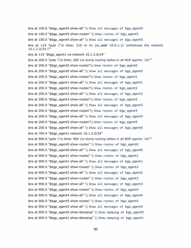
90
$ns at 100.0 "$bgp_agent4 show-all" \\ Show all messages of bgp_agent4
$ns at 100.0 "$bgp_agent5 show-routes" \\ Show routes of bgp_agent5
$ns at 100.0 "$bgp_agent5 show-all" \\ Show all messages of bgp_agent5
$ns at 110 "puts \"\n time: 110 \n n1 (ip_addr 10.0.1.1) \withdraws the network
10.1.2.0/24.\""
$ns at 110 "$bgp_agent1 no-network 10.1.2.0/24"
$ns at 200.0 "puts \"\n time: 200 \\n dump routing tables in all BGP agents: \n\""
$ns at 200.0 "$bgp_agent0 show-routes"\\ Show routes of bgp_agent0
$ns at 200.0 "$bgp_agent0 show-all" \\ Show all messages of bgp_agent0
$ns at 200.0 "$bgp_agent1 show-routes"\\ Show routes of bgp_agent1
$ns at 200.0 "$bgp_agent1 show-all" \\ Show all messages of bgp_agent1
$ns at 200.0 "$bgp_agent2 show-routes"\\ Show routes of bgp_agent2
$ns at 200.0 "$bgp_agent2 show-all" \\ Show all messages of bgp_agent2
$ns at 200.0 "$bgp_agent3 show-routes"\\ Show routes of bgp_agent3
$ns at 200.0 "$bgp_agent3 show-all" \\ Show all messages of bgp_agent3
$ns at 200.0 "$bgp_agent4 show-routes"\\ Show routes of bgp_agent4
$ns at 200.0 "$bgp_agent4 show-all" \\ Show all messages of bgp_agent4
$ns at 200.0 "$bgp_agent5 show-routes"\\ Show routes of bgp_agent5
$ns at 200.0 "$bgp_agent5 show-all" \\ Show all messages of bgp_agent5
$ns at 700.0 "$bgp_agent1 network 10.1.2.0/24"
$ns at 900.0 "puts \"\n time: 900 \\n dump routing tables in all BGP agents: \n\""
$ns at 900.0 "$bgp_agent0 show-routes" \\ Show routes of bgp_agent0
$ns at 900.0 "$bgp_agent0 show-all" \\ Show all messages of bgp_agent0
$ns at 900.0 "$bgp_agent1 show-routes" \\ Show routes of bgp_agent1
$ns at 900.0 "$bgp_agent1 show-all" \\ Show all messages of bgp_agent1
$ns at 900.0 "$bgp_agent2 show-routes" \\ Show routes of bgp_agent2
$ns at 900.0 "$bgp_agent2 show-all" \\ Show all messages of bgp_agent2
$ns at 900.0 "$bgp_agent3 show-routes" \\ Show routes of bgp_agent3
$ns at 900.0 "$bgp_agent3 show-all" \\ Show all messages of bgp_agent3
$ns at 900.0 "$bgp_agent4 show-routes" \\ Show routes of bgp_agent4
$ns at 900.0 "$bgp_agent4 show-all" \\ Show all messages of bgp_agent4
$ns at 900.0 "$bgp_agent5 show-routes" \\ Show routes of bgp_agent5
$ns at 900.0 "$bgp_agent5 show-all" \\ Show all messages of bgp_agent5
$ns at 905.0 "$bgp_agent0 show-damping" \\ Show damping of bgp_agent0
$ns at 905.0 "$bgp_agent1 show-damping" \\ Show damping of bgp_agent1

91
$ns at 905.0 "$bgp_agent2 show-damping" \\ Show damping of bgp_agent2
$ns at 905.0 "$bgp_agent3 show-damping" \\ Show damping of bgp_agent3
$ns at 905.0 "$bgp_agent4 show-damping" \\ Show damping of bgp_agent4
$ns at 905.0 "$bgp_agent5 show-damping" \\ Show damping of bgp_agent5
$ns at 910.0 "finish"
proc finish {} {
global ns
puts "Simulation finished. "
exit 0
}
puts "Simulation starts..."
$ns run
D.4 Fork Topology
puts "Route Flap Damping Validation Test 4"
set ns [new Simulator] \\ set new simulator
$ns node-config -BGP ON \\ configuring nodes to BGP
set n0 [$ns node 0:10.0.0.1] \\ configuring BGP node 0
set n1 [$ns node 1:10.0.1.1] \\ configuring BGP node 1
set n2 [$ns node 2:10.0.2.1] \\ configuring BGP node 2
set n3 [$ns node 3:10.0.3.1] \\ configuring BGP node 3
set n4 [$ns node 4:10.0.4.1] \\ configuring BGP node 4
set n5 [$ns node 5:10.0.5.1] \\ configuring BGP node 5
set n6 [$ns node 6:10.0.6.1] \\ configuring BGP node 6
set n7 [$ns node 7:10.0.7.1] \\ configuring BGP node 7
set n8 [$ns node 8:10.0.8.1] \\ configuring BGP node 8
set n9 [$ns node 9:10.0.9.1] \\ configuring BGP node 9
set n10 [$ns node 10:10.0.10.1] \\ configuring BGP node 10
$ns node-config -BGP OFF \\ BGP configuring complete
$ns duplex-link $n0 $n1 1Mb 1ms DropTail \\ set link between node 0 and 1 $ns duplex-link $n0 $n3 1Mb 1ms DropTail \\ set link between node 0 and 3
$ns duplex-link $n0 $n4 1Mb 1ms DropTail \\ set link between node 0 and 4
$ns duplex-link $n0 $n2 1Mb 1ms DropTail \\ set link between node 0 and 2
$ns duplex-link $n5 $n1 1Mb 1ms DropTail \\ set link between node 5 and 1
$ns duplex-link $n1 $n3 1Mb 1ms DropTail \\ set link between node 1 and 3
$ns duplex-link $n3 $n4 1Mb 1ms DropTail \\ set link between node 3 and 4
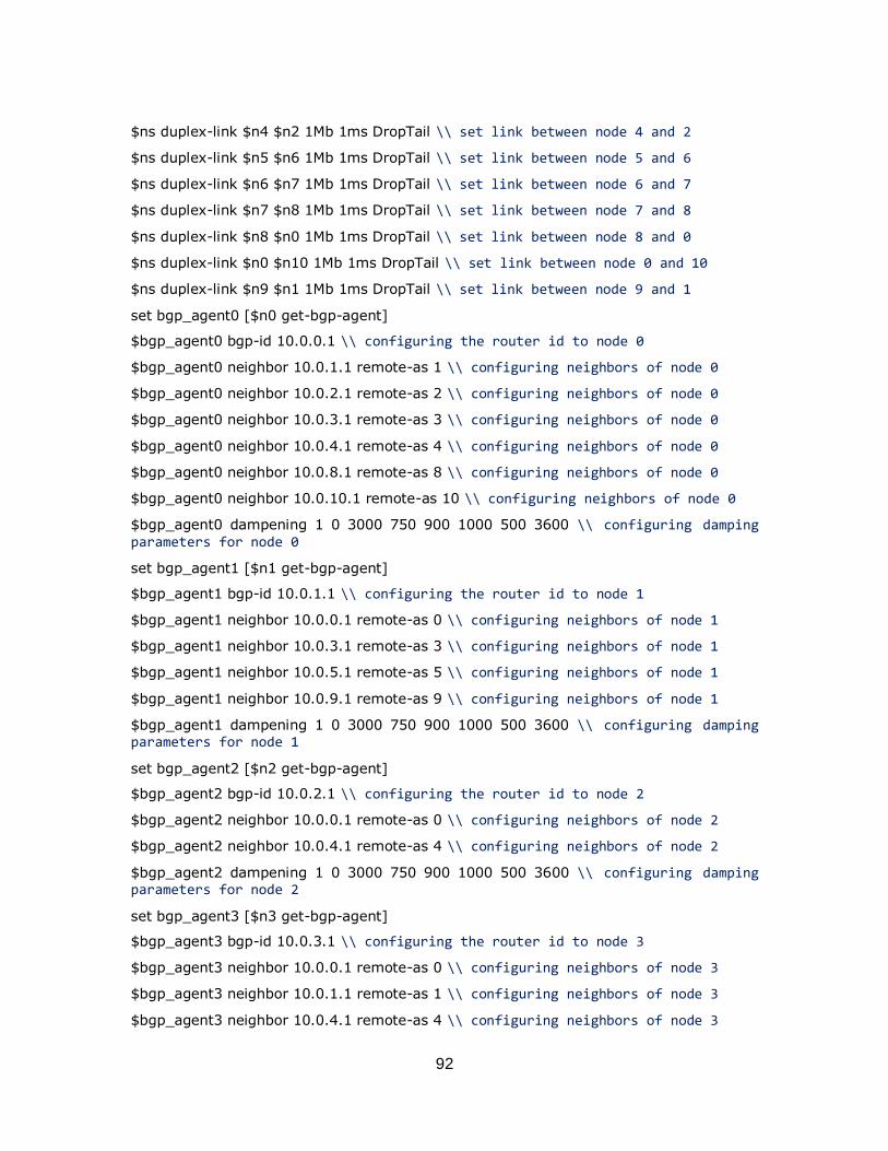
92
$ns duplex-link $n4 $n2 1Mb 1ms DropTail \\ set link between node 4 and 2
$ns duplex-link $n5 $n6 1Mb 1ms DropTail \\ set link between node 5 and 6
$ns duplex-link $n6 $n7 1Mb 1ms DropTail \\ set link between node 6 and 7
$ns duplex-link $n7 $n8 1Mb 1ms DropTail \\ set link between node 7 and 8
$ns duplex-link $n8 $n0 1Mb 1ms DropTail \\ set link between node 8 and 0
$ns duplex-link $n0 $n10 1Mb 1ms DropTail \\ set link between node 0 and 10
$ns duplex-link $n9 $n1 1Mb 1ms DropTail \\ set link between node 9 and 1
set bgp_agent0 [$n0 get-bgp-agent]
$bgp_agent0 bgp-id 10.0.0.1 \\ configuring the router id to node 0
$bgp_agent0 neighbor 10.0.1.1 remote-as 1 \\ configuring neighbors of node 0
$bgp_agent0 neighbor 10.0.2.1 remote-as 2 \\ configuring neighbors of node 0
$bgp_agent0 neighbor 10.0.3.1 remote-as 3 \\ configuring neighbors of node 0
$bgp_agent0 neighbor 10.0.4.1 remote-as 4 \\ configuring neighbors of node 0
$bgp_agent0 neighbor 10.0.8.1 remote-as 8 \\ configuring neighbors of node 0
$bgp_agent0 neighbor 10.0.10.1 remote-as 10 \\ configuring neighbors of node 0
$bgp_agent0 dampening 1 0 3000 750 900 1000 500 3600 \\ configuring damping parameters for node 0
set bgp_agent1 [$n1 get-bgp-agent]
$bgp_agent1 bgp-id 10.0.1.1 \\ configuring the router id to node 1
$bgp_agent1 neighbor 10.0.0.1 remote-as 0 \\ configuring neighbors of node 1
$bgp_agent1 neighbor 10.0.3.1 remote-as 3 \\ configuring neighbors of node 1
$bgp_agent1 neighbor 10.0.5.1 remote-as 5 \\ configuring neighbors of node 1
$bgp_agent1 neighbor 10.0.9.1 remote-as 9 \\ configuring neighbors of node 1
$bgp_agent1 dampening 1 0 3000 750 900 1000 500 3600 \\ configuring damping parameters for node 1
set bgp_agent2 [$n2 get-bgp-agent]
$bgp_agent2 bgp-id 10.0.2.1 \\ configuring the router id to node 2
$bgp_agent2 neighbor 10.0.0.1 remote-as 0 \\ configuring neighbors of node 2
$bgp_agent2 neighbor 10.0.4.1 remote-as 4 \\ configuring neighbors of node 2
$bgp_agent2 dampening 1 0 3000 750 900 1000 500 3600 \\ configuring damping parameters for node 2
set bgp_agent3 [$n3 get-bgp-agent]
$bgp_agent3 bgp-id 10.0.3.1 \\ configuring the router id to node 3
$bgp_agent3 neighbor 10.0.0.1 remote-as 0 \\ configuring neighbors of node 3
$bgp_agent3 neighbor 10.0.1.1 remote-as 1 \\ configuring neighbors of node 3
$bgp_agent3 neighbor 10.0.4.1 remote-as 4 \\ configuring neighbors of node 3
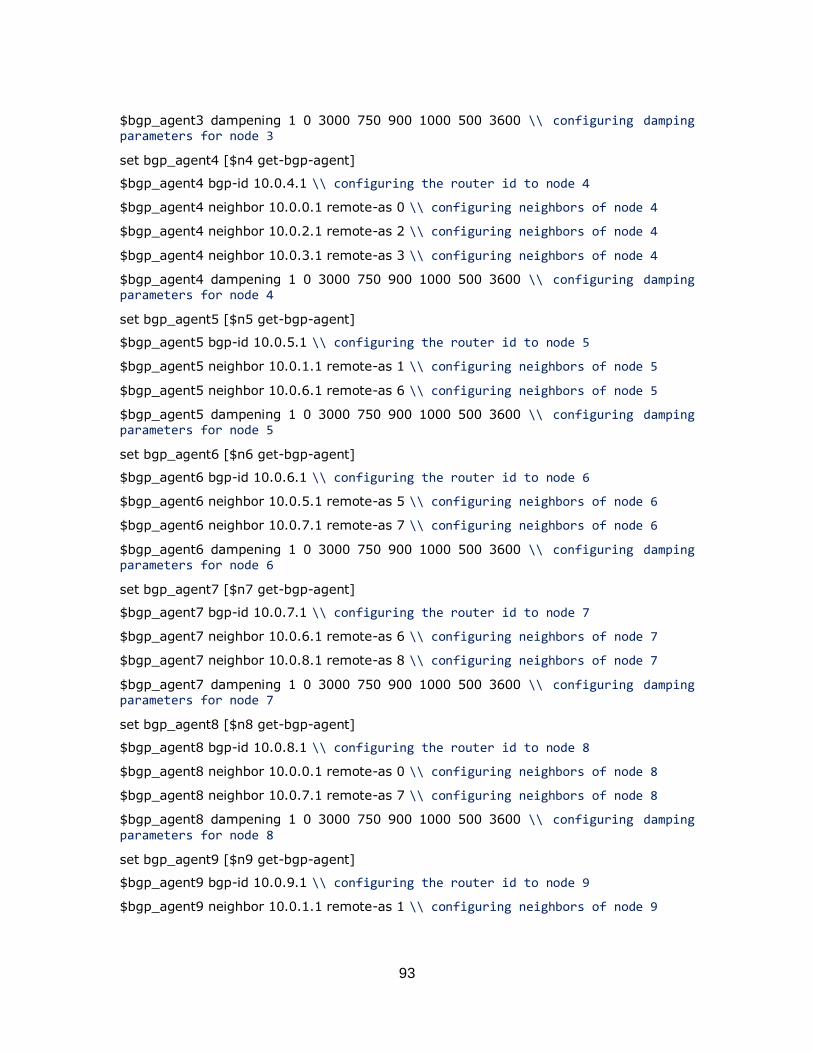
93
$bgp_agent3 dampening 1 0 3000 750 900 1000 500 3600 \\ configuring damping parameters for node 3
set bgp_agent4 [$n4 get-bgp-agent]
$bgp_agent4 bgp-id 10.0.4.1 \\ configuring the router id to node 4
$bgp_agent4 neighbor 10.0.0.1 remote-as 0 \\ configuring neighbors of node 4
$bgp_agent4 neighbor 10.0.2.1 remote-as 2 \\ configuring neighbors of node 4
$bgp_agent4 neighbor 10.0.3.1 remote-as 3 \\ configuring neighbors of node 4
$bgp_agent4 dampening 1 0 3000 750 900 1000 500 3600 \\ configuring damping parameters for node 4
set bgp_agent5 [$n5 get-bgp-agent]
$bgp_agent5 bgp-id 10.0.5.1 \\ configuring the router id to node 5
$bgp_agent5 neighbor 10.0.1.1 remote-as 1 \\ configuring neighbors of node 5
$bgp_agent5 neighbor 10.0.6.1 remote-as 6 \\ configuring neighbors of node 5
$bgp_agent5 dampening 1 0 3000 750 900 1000 500 3600 \\ configuring damping parameters for node 5
set bgp_agent6 [$n6 get-bgp-agent]
$bgp_agent6 bgp-id 10.0.6.1 \\ configuring the router id to node 6
$bgp_agent6 neighbor 10.0.5.1 remote-as 5 \\ configuring neighbors of node 6
$bgp_agent6 neighbor 10.0.7.1 remote-as 7 \\ configuring neighbors of node 6
$bgp_agent6 dampening 1 0 3000 750 900 1000 500 3600 \\ configuring damping parameters for node 6
set bgp_agent7 [$n7 get-bgp-agent]
$bgp_agent7 bgp-id 10.0.7.1 \\ configuring the router id to node 7
$bgp_agent7 neighbor 10.0.6.1 remote-as 6 \\ configuring neighbors of node 7
$bgp_agent7 neighbor 10.0.8.1 remote-as 8 \\ configuring neighbors of node 7
$bgp_agent7 dampening 1 0 3000 750 900 1000 500 3600 \\ configuring damping parameters for node 7
set bgp_agent8 [$n8 get-bgp-agent]
$bgp_agent8 bgp-id 10.0.8.1 \\ configuring the router id to node 8
$bgp_agent8 neighbor 10.0.0.1 remote-as 0 \\ configuring neighbors of node 8
$bgp_agent8 neighbor 10.0.7.1 remote-as 7 \\ configuring neighbors of node 8
$bgp_agent8 dampening 1 0 3000 750 900 1000 500 3600 \\ configuring damping parameters for node 8
set bgp_agent9 [$n9 get-bgp-agent]
$bgp_agent9 bgp-id 10.0.9.1 \\ configuring the router id to node 9
$bgp_agent9 neighbor 10.0.1.1 remote-as 1 \\ configuring neighbors of node 9
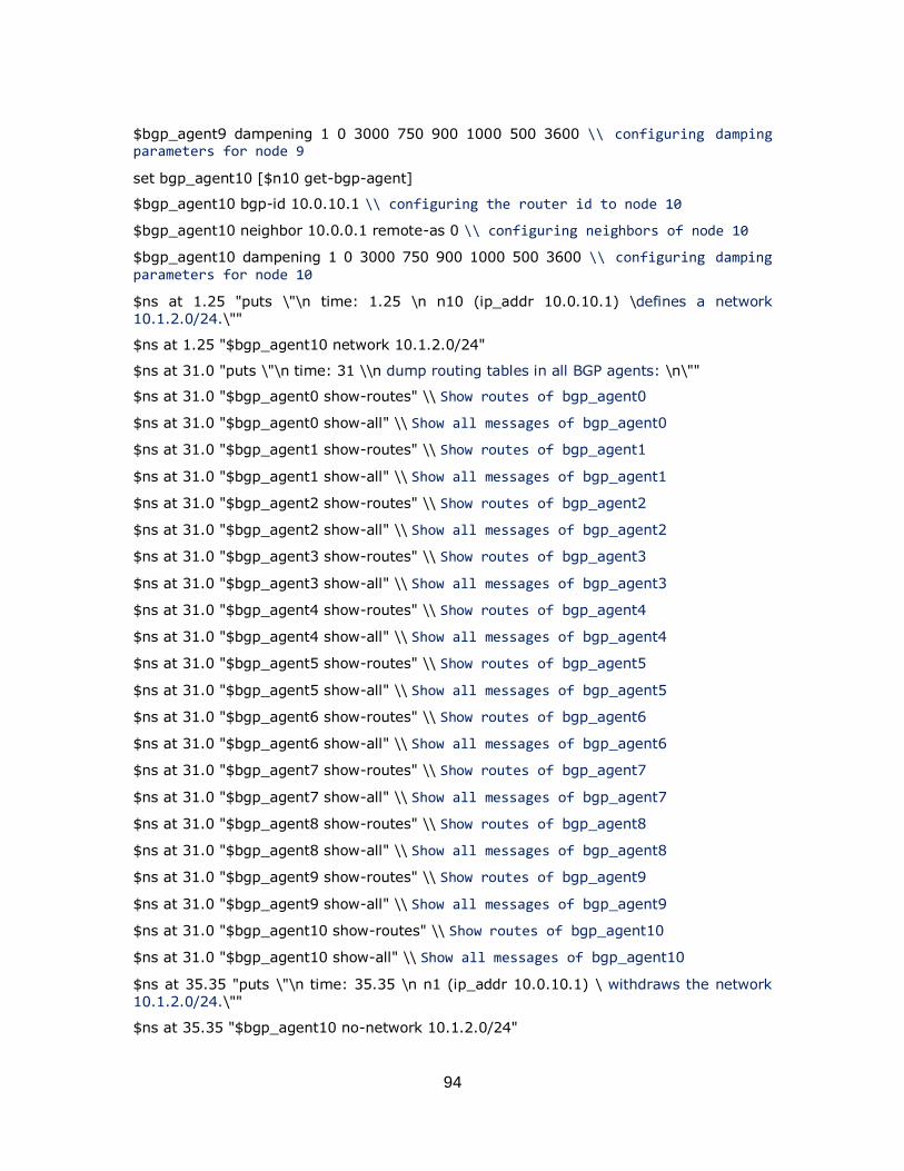
94
$bgp_agent9 dampening 1 0 3000 750 900 1000 500 3600 \\ configuring damping parameters for node 9
set bgp_agent10 [$n10 get-bgp-agent]
$bgp_agent10 bgp-id 10.0.10.1 \\ configuring the router id to node 10
$bgp_agent10 neighbor 10.0.0.1 remote-as 0 \\ configuring neighbors of node 10
$bgp_agent10 dampening 1 0 3000 750 900 1000 500 3600 \\ configuring damping parameters for node 10
$ns at 1.25 "puts \"\n time: 1.25 \n n10 (ip_addr 10.0.10.1) \defines a network
10.1.2.0/24.\""
$ns at 1.25 "$bgp_agent10 network 10.1.2.0/24"
$ns at 31.0 "puts \"\n time: 31 \\n dump routing tables in all BGP agents: \n\""
$ns at 31.0 "$bgp_agent0 show-routes" \\ Show routes of bgp_agent0
$ns at 31.0 "$bgp_agent0 show-all" \\ Show all messages of bgp_agent0
$ns at 31.0 "$bgp_agent1 show-routes" \\ Show routes of bgp_agent1
$ns at 31.0 "$bgp_agent1 show-all" \\ Show all messages of bgp_agent1
$ns at 31.0 "$bgp_agent2 show-routes" \\ Show routes of bgp_agent2
$ns at 31.0 "$bgp_agent2 show-all" \\ Show all messages of bgp_agent2
$ns at 31.0 "$bgp_agent3 show-routes" \\ Show routes of bgp_agent3
$ns at 31.0 "$bgp_agent3 show-all" \\ Show all messages of bgp_agent3
$ns at 31.0 "$bgp_agent4 show-routes" \\ Show routes of bgp_agent4
$ns at 31.0 "$bgp_agent4 show-all" \\ Show all messages of bgp_agent4
$ns at 31.0 "$bgp_agent5 show-routes" \\ Show routes of bgp_agent5
$ns at 31.0 "$bgp_agent5 show-all" \\ Show all messages of bgp_agent5
$ns at 31.0 "$bgp_agent6 show-routes" \\ Show routes of bgp_agent6
$ns at 31.0 "$bgp_agent6 show-all" \\ Show all messages of bgp_agent6
$ns at 31.0 "$bgp_agent7 show-routes" \\ Show routes of bgp_agent7
$ns at 31.0 "$bgp_agent7 show-all" \\ Show all messages of bgp_agent7
$ns at 31.0 "$bgp_agent8 show-routes" \\ Show routes of bgp_agent8
$ns at 31.0 "$bgp_agent8 show-all" \\ Show all messages of bgp_agent8
$ns at 31.0 "$bgp_agent9 show-routes" \\ Show routes of bgp_agent9
$ns at 31.0 "$bgp_agent9 show-all" \\ Show all messages of bgp_agent9
$ns at 31.0 "$bgp_agent10 show-routes" \\ Show routes of bgp_agent10
$ns at 31.0 "$bgp_agent10 show-all" \\ Show all messages of bgp_agent10
$ns at 35.35 "puts \"\n time: 35.35 \n n1 (ip_addr 10.0.10.1) \ withdraws the network
10.1.2.0/24.\""
$ns at 35.35 "$bgp_agent10 no-network 10.1.2.0/24"
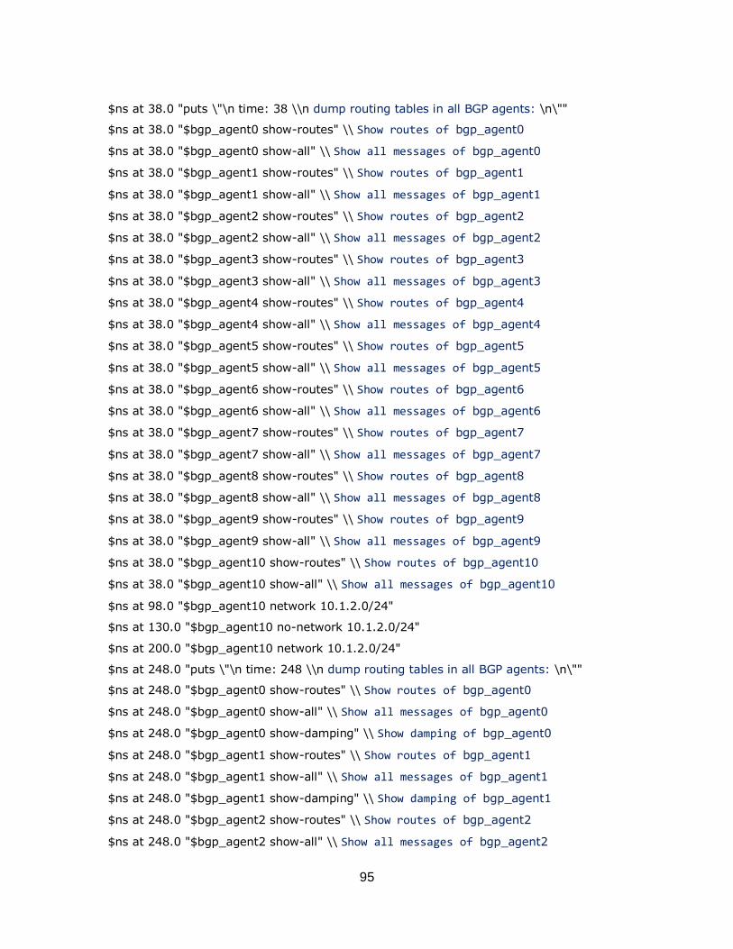
95
$ns at 38.0 "puts \"\n time: 38 \\n dump routing tables in all BGP agents: \n\""
$ns at 38.0 "$bgp_agent0 show-routes" \\ Show routes of bgp_agent0
$ns at 38.0 "$bgp_agent0 show-all" \\ Show all messages of bgp_agent0
$ns at 38.0 "$bgp_agent1 show-routes" \\ Show routes of bgp_agent1
$ns at 38.0 "$bgp_agent1 show-all" \\ Show all messages of bgp_agent1
$ns at 38.0 "$bgp_agent2 show-routes" \\ Show routes of bgp_agent2
$ns at 38.0 "$bgp_agent2 show-all" \\ Show all messages of bgp_agent2
$ns at 38.0 "$bgp_agent3 show-routes" \\ Show routes of bgp_agent3
$ns at 38.0 "$bgp_agent3 show-all" \\ Show all messages of bgp_agent3
$ns at 38.0 "$bgp_agent4 show-routes" \\ Show routes of bgp_agent4
$ns at 38.0 "$bgp_agent4 show-all" \\ Show all messages of bgp_agent4
$ns at 38.0 "$bgp_agent5 show-routes" \\ Show routes of bgp_agent5
$ns at 38.0 "$bgp_agent5 show-all" \\ Show all messages of bgp_agent5
$ns at 38.0 "$bgp_agent6 show-routes" \\ Show routes of bgp_agent6
$ns at 38.0 "$bgp_agent6 show-all" \\ Show all messages of bgp_agent6
$ns at 38.0 "$bgp_agent7 show-routes" \\ Show routes of bgp_agent7
$ns at 38.0 "$bgp_agent7 show-all" \\ Show all messages of bgp_agent7
$ns at 38.0 "$bgp_agent8 show-routes" \\ Show routes of bgp_agent8
$ns at 38.0 "$bgp_agent8 show-all" \\ Show all messages of bgp_agent8
$ns at 38.0 "$bgp_agent9 show-routes" \\ Show routes of bgp_agent9
$ns at 38.0 "$bgp_agent9 show-all" \\ Show all messages of bgp_agent9
$ns at 38.0 "$bgp_agent10 show-routes" \\ Show routes of bgp_agent10
$ns at 38.0 "$bgp_agent10 show-all" \\ Show all messages of bgp_agent10
$ns at 98.0 "$bgp_agent10 network 10.1.2.0/24"
$ns at 130.0 "$bgp_agent10 no-network 10.1.2.0/24"
$ns at 200.0 "$bgp_agent10 network 10.1.2.0/24"
$ns at 248.0 "puts \"\n time: 248 \\n dump routing tables in all BGP agents: \n\""
$ns at 248.0 "$bgp_agent0 show-routes" \\ Show routes of bgp_agent0
$ns at 248.0 "$bgp_agent0 show-all" \\ Show all messages of bgp_agent0
$ns at 248.0 "$bgp_agent0 show-damping" \\ Show damping of bgp_agent0
$ns at 248.0 "$bgp_agent1 show-routes" \\ Show routes of bgp_agent1
$ns at 248.0 "$bgp_agent1 show-all" \\ Show all messages of bgp_agent1
$ns at 248.0 "$bgp_agent1 show-damping" \\ Show damping of bgp_agent1
$ns at 248.0 "$bgp_agent2 show-routes" \\ Show routes of bgp_agent2
$ns at 248.0 "$bgp_agent2 show-all" \\ Show all messages of bgp_agent2
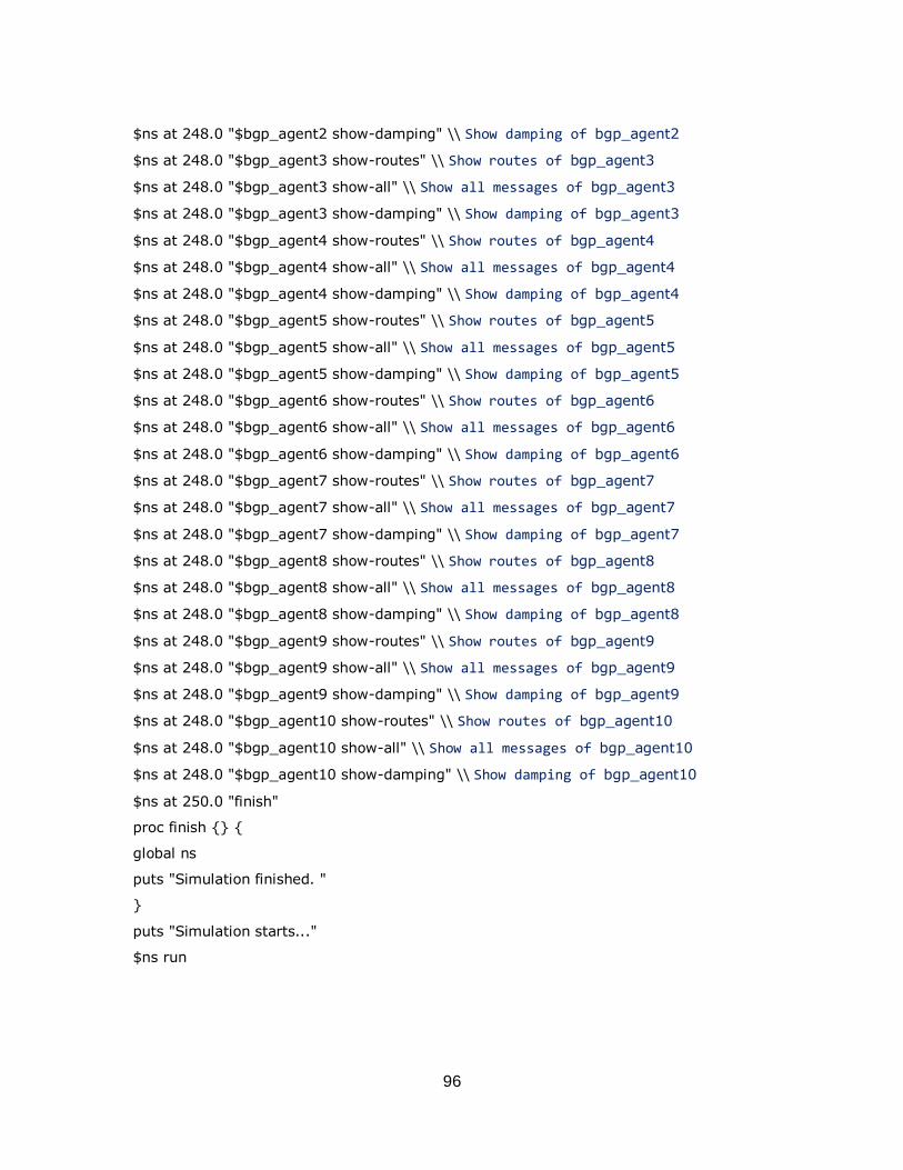
96
$ns at 248.0 "$bgp_agent2 show-damping" \\ Show damping of bgp_agent2
$ns at 248.0 "$bgp_agent3 show-routes" \\ Show routes of bgp_agent3
$ns at 248.0 "$bgp_agent3 show-all" \\ Show all messages of bgp_agent3
$ns at 248.0 "$bgp_agent3 show-damping" \\ Show damping of bgp_agent3
$ns at 248.0 "$bgp_agent4 show-routes" \\ Show routes of bgp_agent4
$ns at 248.0 "$bgp_agent4 show-all" \\ Show all messages of bgp_agent4
$ns at 248.0 "$bgp_agent4 show-damping" \\ Show damping of bgp_agent4
$ns at 248.0 "$bgp_agent5 show-routes" \\ Show routes of bgp_agent5
$ns at 248.0 "$bgp_agent5 show-all" \\ Show all messages of bgp_agent5
$ns at 248.0 "$bgp_agent5 show-damping" \\ Show damping of bgp_agent5
$ns at 248.0 "$bgp_agent6 show-routes" \\ Show routes of bgp_agent6
$ns at 248.0 "$bgp_agent6 show-all" \\ Show all messages of bgp_agent6
$ns at 248.0 "$bgp_agent6 show-damping" \\ Show damping of bgp_agent6
$ns at 248.0 "$bgp_agent7 show-routes" \\ Show routes of bgp_agent7
$ns at 248.0 "$bgp_agent7 show-all" \\ Show all messages of bgp_agent7
$ns at 248.0 "$bgp_agent7 show-damping" \\ Show damping of bgp_agent7
$ns at 248.0 "$bgp_agent8 show-routes" \\ Show routes of bgp_agent8
$ns at 248.0 "$bgp_agent8 show-all" \\ Show all messages of bgp_agent8
$ns at 248.0 "$bgp_agent8 show-damping" \\ Show damping of bgp_agent8
$ns at 248.0 "$bgp_agent9 show-routes" \\ Show routes of bgp_agent9
$ns at 248.0 "$bgp_agent9 show-all" \\ Show all messages of bgp_agent9
$ns at 248.0 "$bgp_agent9 show-damping" \\ Show damping of bgp_agent9
$ns at 248.0 "$bgp_agent10 show-routes" \\ Show routes of bgp_agent10
$ns at 248.0 "$bgp_agent10 show-all" \\ Show all messages of bgp_agent10
$ns at 248.0 "$bgp_agent10 show-damping" \\ Show damping of bgp_agent10
$ns at 250.0 "finish"
proc finish {} {
global ns
puts "Simulation finished. "
}
puts "Simulation starts..."
$ns run