Embed Size (px)
Citation preview
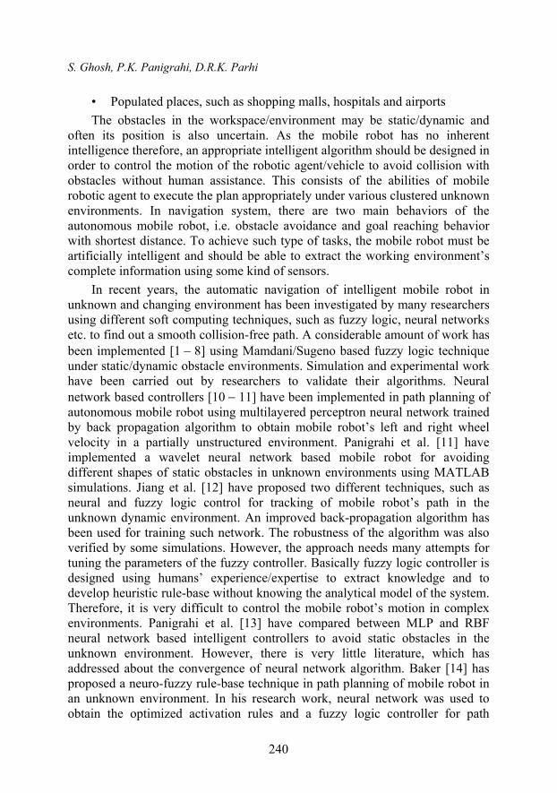
SERBIAN JOURNAL OF ELECTRICAL ENGINEERING Vol. 13, No. 2, June 2016, 239-263
239
Performance Comparison of Novel WNN Approach with RBFNN in Navigation of Autonomous Mobile Robotic Agent
Saradindu Ghosh1, Pratap Kumar Panigrahi2, Dayal R. Parhi3
Abstract: This paper addresses the performance comparison of Radial Basis Function Neural Network (RBFNN) with novel Wavelet Neural Network (WNN) of designing intelligent controllers for path planning of mobile robot in an unknown environment. In the proposed WNN, different types of activation functions such as Mexican Hat, Gaussian and Morlet wavelet functions are used in the hidden nodes. The neural networks are trained by an intelligent supervised learning technique so that the robot makes a collision-free path in the unknown environment during navigation from different starting points to targets/goals. The efficiency of two algorithms is compared using some MATLAB simulations and experimental setup with Arduino Mega 2560 microcontroller in terms of path length and time taken to reach the target as an indicator for the accuracy of the network models.
Keywords: Autonomous Navigation, Collision Avoidance, Radial Basis Function Neural Network, Wavelet Neural Network.
1 Introduction
Autonomous navigation of mobile robotic agent is the ability of the robot to move in an unknown environment with obstacles based on its knowledge/intelligence and the sensor information in order to reach the target point without collision. Such type of mobile robot has wide applications in the real world life where human being is unsafe to work. In recent years, it has been employed in
• Automatic driving of vehicles
• Material handling/transportation and household services
• Military, agriculture, mining etc.
1Prof. Electrical Eng., National Institute of Technology, Durgapur, West Bengal, India; E-mail: [email protected]
2Asst. Prof. Electrical Eng., Padmanava College of Engineering, Rourkela; E-mail: [email protected]
3Prof. Mechanical Eng., National Institute of Technology, Rourkela, Odisha, India; E-mail: [email protected]
UDC: 007.52:004.42MATLAB DOI: 10.2298/SJEE1602239G
S. Ghosh, P.K. Panigrahi, D.R.K. Parhi
240
• Populated places, such as shopping malls, hospitals and airports
The obstacles in the workspace/environment may be static/dynamic and often its position is also uncertain. As the mobile robot has no inherent intelligence therefore, an appropriate intelligent algorithm should be designed in order to control the motion of the robotic agent/vehicle to avoid collision with obstacles without human assistance. This consists of the abilities of mobile robotic agent to execute the plan appropriately under various clustered unknown environments. In navigation system, there are two main behaviors of the autonomous mobile robot, i.e. obstacle avoidance and goal reaching behavior with shortest distance. To achieve such type of tasks, the mobile robot must be artificially intelligent and should be able to extract the working environment’s complete information using some kind of sensors.
In recent years, the automatic navigation of intelligent mobile robot in unknown and changing environment has been investigated by many researchers using different soft computing techniques, such as fuzzy logic, neural networks etc. to find out a smooth collision-free path. A considerable amount of work has been implemented [1 8] using Mamdani/Sugeno based fuzzy logic technique under static/dynamic obstacle environments. Simulation and experimental work have been carried out by researchers to validate their algorithms. Neural network based controllers [10 11] have been implemented in path planning of autonomous mobile robot using multilayered perceptron neural network trained by back propagation algorithm to obtain mobile robot’s left and right wheel velocity in a partially unstructured environment. Panigrahi et al. [11] have implemented a wavelet neural network based mobile robot for avoiding different shapes of static obstacles in unknown environments using MATLAB simulations. Jiang et al. [12] have proposed two different techniques, such as neural and fuzzy logic control for tracking of mobile robot’s path in the unknown dynamic environment. An improved back-propagation algorithm has been used for training such network. The robustness of the algorithm was also verified by some simulations. However, the approach needs many attempts for tuning the parameters of the fuzzy controller. Basically fuzzy logic controller is designed using humans’ experience/expertise to extract knowledge and to develop heuristic rule-base without knowing the analytical model of the system. Therefore, it is very difficult to control the mobile robot’s motion in complex environments. Panigrahi et al. [13] have compared between MLP and RBF neural network based intelligent controllers to avoid static obstacles in the unknown environment. However, there is very little literature, which has addressed about the convergence of neural network algorithm. Baker [14] has proposed a neuro-fuzzy rule-base technique in path planning of mobile robot in an unknown environment. In his research work, neural network was used to obtain the optimized activation rules and a fuzzy logic controller for path
Performance Comparison of Novel WNN Approach with RBFNN in Navigation …
241
planning of robot during navigation. Gigras et al. [15] have implemented an ant colony optimization algorithm to obtain an optimized collision free navigational path with respect to path length and time. The efficiency of the algorithm was verified with simulations. Castro et al. [16] have proposed an algorithm to control robot’s motion during navigation in a partially structured environment using the probabilistic neural network. Buniyamin et al. [17] have discussed an algorithm, based on the measurement of shortest distance obstacles using sensors for path planning of mobile robot in a static environment. The algorithm was designed to minimize the use of obstacle’s outer perimeter to generate a complete collision free path from starting point to a destination. Yang and Meng [18] have proposed a biologically artificial neural network based technique in real-world environment for collision-free motion of mobile robot in path planning problem. Braganza et al. [19] have described a path motion-planning controller using neural network feedforward configuration to compensate the dynamic uncertainties. Singh and Parhi [20] have proposed an artificial neural network based controller for path optimization using mobile robot in different complex environments. Multi-layer perceptron architecture with back propagation training algorithm is used in the algorithm. Kondo [21] has described an online learning ability based algorithm instead of weight adjustment parameter based algorithm in simulated platform. Corradini et al. [22] have used a neural network approach with mobile robot in tracking problem. Er et al. [23] have deigned a genetic algorithm based reinforcement learning which determines its behavior appropriately to adapt the problems caused by broken sensors so that the autonomous mobile robot moves in the unknown environments without hitting with obstacles. Zhang et al. [24] have presented a simplified control structure for the trajectory tracking design of non-holonomic wheeled mobile robots using H2 and H-infinity control methods. Panigrahi et al. [25] have implemented a probabilistic neural network based controller to obtain a non-collision free path during navigation of robot in unknown static obstacle environments. Velagic et al. [26] have proposed a neural network based path planning controller. But the optimal selection of synaptic weights of the given architecture is difficult. However, there are some other techniques, like artificial potential field, vector field histogram etc. have been used to solve such type of problems. Intelligent neural network [27 30] based reinforcement learning rules has been used to learn the reaction of mobile robot for robotic manipulators and mobile robot navigation. The above review work suggests that ANN can offer promising solutions in robotic navigation problem, because of their ability to learn complex non-linear relationship between input sensors values and output control variables. Thus, some new kind of intelligent and faster ANN controller is required that can cope with artificial intelligence techniques for obtaining a smooth and optimum collision free path for real time motion planning of mobile robot in different types of static
S. Ghosh, P.K. Panigrahi, D.R.K. Parhi
242
obstacle environments. The proposed algorithm is based on obstacle avoidance and goal reaching behavior. The main objective of this work is to compare the performance of RBFNN based path planner with the proposed WNN based in terms of path length, travel time, learning speed and guarantee of convergence in the application of navigation of mobile robot in different clustered environments.
2 Mobile Robot Configuration and Kinematic Analysis
Fig.1 represents a mobile robot with multiple obstacles in the environment. The robot is to move in an unknown environment with target angle ( ) so as to reach from starting location to any destination/goal without collision by avoiding a set of obstacles.
Front obstacles
Left obstacles
Target
Right obstacles
Robot Back obstacles
Fig. 1 Environment of mobile robot.
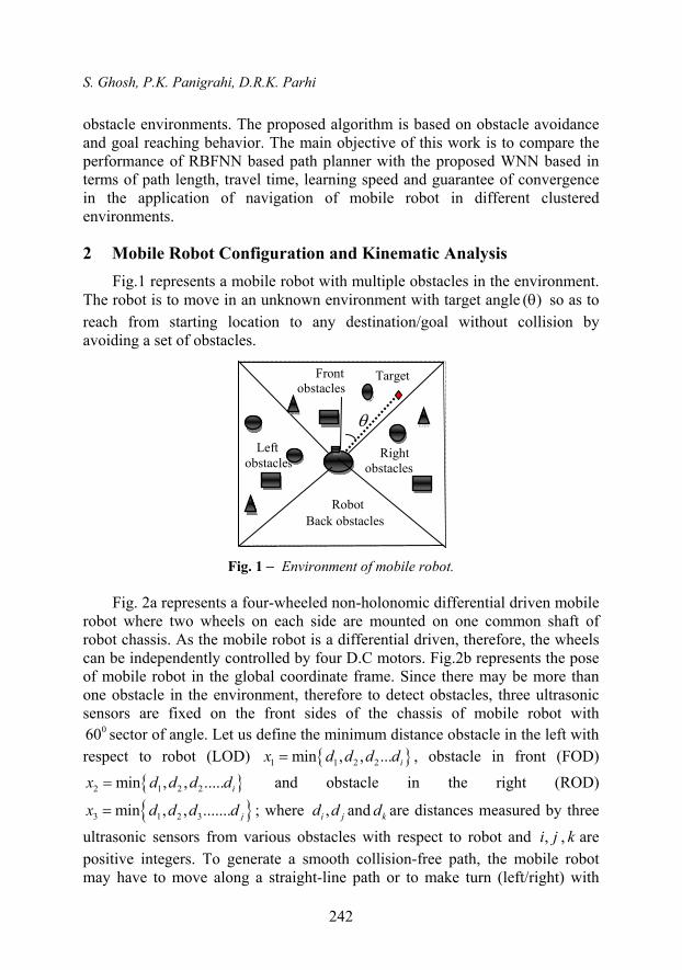
Fig. 2a represents a four-wheeled non-holonomic differential driven mobile
robot where two wheels on each side are mounted on one common shaft of robot chassis. As the mobile robot is a differential driven, therefore, the wheels can be independently controlled by four D.C motors. Fig.2b represents the pose of mobile robot in the global coordinate frame. Since there may be more than one obstacle in the environment, therefore to detect obstacles, three ultrasonic sensors are fixed on the front sides of the chassis of mobile robot with
060 sector of angle. Let us define the minimum distance obstacle in the left with respect to robot (LOD) 1 1 2 2min , , ... ix d d d d , obstacle in front (FOD)
2 1 2 2min , , ..... ix d d d d and obstacle in the right (ROD)
3 1 2 3min , , ....... jx d d d d ; where ,i jd d and kd are distances measured by three
ultrasonic sensors from various obstacles with respect to robot and ,i j , k are positive integers. To generate a smooth collision-free path, the mobile robot may have to move along a straight-line path or to make turn (left/right) with
Performance Comparison of Novel WNN Approach with RBFNN in Navigation …
243
appropriate steering angle depending on the position of the obstacles in the environment. To do so, four inputs are included for neural network, such as LOD, FOD, ROD, target/goal angle (TA) and one output called steering angle (SA). During navigation, the target angle is given at all time to the robot. The environment may contain static obstacles of different shapes and sizes.
As mentioned in Fig. 2a, the following notations are considered during kinematic analysis of robot, i.e. is the mobile robot’s steering angle, d is the
distance from front to rear axle, is the target/ goal angle of robot, R is the radius of curvature, w is the angular velocity, Lv and Rv are ground left and right rear wheels’ linear velocities, r is each wheel’s radius and L is the distance between two rear wheels.
O X O
Target
y
x
Y
Lv
Y
x
ICC
X
r
Rv
v
L By O
R
d
Fig. 2a Four-wheel mobile robot. Fig. 2b Robot pose in global coordinate.
2.1 Assumptions
The following assumptions are considered:
(i) The mobile robot must rotate about a point, called as the instantaneous center of curvature;
(ii) No slippage: wheels do not slip during rolling;
(iii) The traveled distance is assumed to be equal to r ;
(iv) Lateral slippage may be neglected.
2.2 Analysis
The robot has 2 degrees of freedom; ( , )x y , are the position and heading
or target angle of robot; is the steering angle of robot; the coordinate ( , , )x y is the pose of the robot in the plane. Fig. 2b is the robot pose in global co-ordinate system. Referring Fig. 2a the radius of curvature is
S. Ghosh, P.K. Panigrahi, D.R.K. Parhi
244
tan2
R d
. (1)
1 12 2 22 2
2( )
tan2
V V Vw
B d Rd d
, (2)
0 010 0 2 2
2
d d
tan2
t t Vw
d d
, (3)
Here cos , sin ,x yV V V V
0 00 0 0 0d cos d , d sin d
t r t r
x yx V V x y V V y .
3 Radial Basis Function Neural Network (RBFNN)
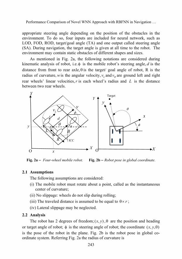
The basic RBFNN structure in Fig. 3a consists of three layers; an input layer, a kernel layer (hidden layer) and an output layer.
( )k x
Steering Angle
1 ( )LODx
2 ( )x FOD
kw
3 ( )x ROD
4 ( )x TA
Fig. 3a Configuration of RBFNN.
The kernel layer consists of a set of kernel basis functions, called radial basis functions. Each radial basis function (RBF) has two key parameters, i.e. center and width. The hidden nodes measure the distance between the input vector and center of RBF. The RBF attains a peak value when the distance between center and input vector is zero and decreases gradually as the distance increases. Each neuron in the hidden layer utilizes Gaussian function as an activation function. The output of RBFNN is a linear combination of (weighted sum) radial basis functions calculated by kernel units. The general radial basis output equation for interpolation of the network is
Performance Comparison of Novel WNN Approach with RBFNN in Navigation …
245
1
( ) . ( )i
k kk
f x w x
, (4)
where 2
2( ) exp
2k
kk
x cx
denotes the thk hidden node radial basis
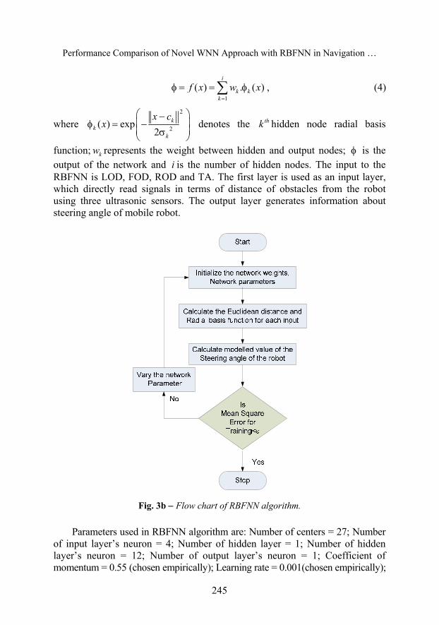
function; kw represents the weight between hidden and output nodes; is the output of the network and i is the number of hidden nodes. The input to the RBFNN is LOD, FOD, ROD and TA. The first layer is used as an input layer, which directly read signals in terms of distance of obstacles from the robot using three ultrasonic sensors. The output layer generates information about steering angle of mobile robot.
Fig. 3b Flow chart of RBFNN algorithm.
Parameters used in RBFNN algorithm are: Number of centers = 27; Number of input layer’s neuron = 4; Number of hidden layer = 1; Number of hidden layer’s neuron = 12; Number of output layer’s neuron = 1; Coefficient of momentum = 0.55 (chosen empirically); Learning rate = 0.001(chosen empirically);
S. Ghosh, P.K. Panigrahi, D.R.K. Parhi
246
Learning algorithm = Gradient descent with momentum (traingdm); Transfer function = Tangent Sigmoidal (tansig).
The flowchart concerned with the problem is represented in Fig. 3b. The RBF network is trained using gradient descent method. The gradient descent method is an effective method to train RBF neural network for approximation. Using gradient descent method, the parameters can be updated as follows:
( ) ( ( ) ( ))k d kk
Ew t t t
w
, (5)
( ) ( 1) ( ) ( ( 1) ( 2)k k k k kw t w t w t w t w t , (6)
2
3( ( ) ( )) k
k d k kk k
x cEt t w
, (7)
( ) ( 1) ( ( 1) ( 2)k k k k kt t t t , (8)
2
( ( ) ( )) k kiki d k
ki k
x cEc t t w
c
, (9)
( ) ( 1) ( ( 1) ( 2)ki ki ki ki kic t c t c c t c t , (10)
where (0,1) is the learning is rate and (0,1) is the momentum factor. A measure of the performance of the network is the instantaneous sum-square difference between d (desired) and a (actual) for the given training patterns.
During training, the RBF output a may differ from the desired output d for the set of given training patterns.
21( )
2 d aE . (11)
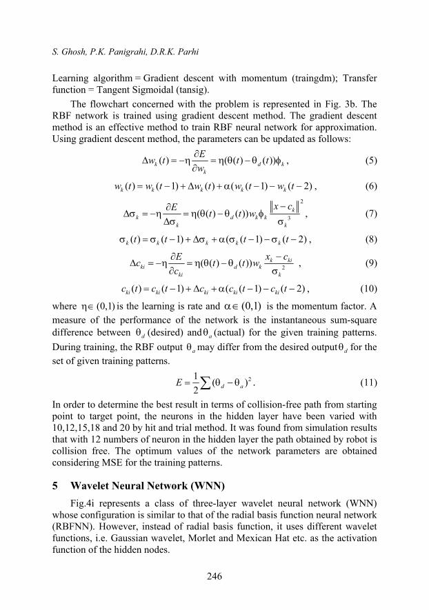
In order to determine the best result in terms of collision-free path from starting point to target point, the neurons in the hidden layer have been varied with 10,12,15,18 and 20 by hit and trial method. It was found from simulation results that with 12 numbers of neuron in the hidden layer the path obtained by robot is collision free. The optimum values of the network parameters are obtained considering MSE for the training patterns.
5 Wavelet Neural Network (WNN)
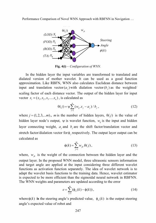
Fig.4i represents a class of three-layer wavelet neural network (WNN) whose configuration is similar to that of the radial basis function neural network (RBFNN). However, instead of radial basis function, it uses different wavelet functions, i.e. Gaussian wavelet, Morlet and Mexican Hat etc. as the activation function of the hidden nodes.
Performance Comparison of Novel WNN Approach with RBFNN in Navigation …
247
jkw
( )
Steering
Angle
k
(LOD) 1x
(FOD) 2x
(ROD) 3x
(TA) 4x
( )j ( )j
Fig. 4(i) Configuration of WNN.
In the hidden layer the input variables are transformed to translated and dialated version of mother wavelet. It can be used as a good function approximation. Like RBFN, WNN also calculates Euclidean distance between input and translation vector ( )ja with dialation vector ( )jb as the weighted/
scaling factor of each distance vector. The output of the hidden layer for input vector 1 2 3( , , ..... )i nx x x x x , is calculated as
1
( ) ( . ) /n
ij j j ji
j w x a b
, (12)
where (1,2,3,... )j m , m is the number of hidden layers, ( )j is the value of
hidden layer node’s output, is wavelet function, ijw is the input and hidden
layer connecting weight, ja and jb are the shift factor/translation vector and
stretch factor/dialation vector for j respectively. The output layer output can be
calculated as
1
( ) . ( )m
jkj
k w j
, (13)
where, jkw is the weight of the connection between the hidden layer and the
output layer. In the proposed WNN model, three ultrasonic sensors information and target angle are applied at the input considering three different wavelet functions as activation function separately. The idea of wavelet network is to adapt the wavelet basis functions to the training data. Hence, wavelet estimator is expected to be more efficient than the sigmoidal neural network in RBFNN. The WNN weights and parameters are updated according to the error
1
( ( ) ( ))m
ni
e k k
, (14)
where ( )k is the steering angle’s predicted value, ( )n k is the output steering angle’s expected value of robot and
S. Ghosh, P.K. Panigrahi, D.R.K. Parhi
248
( 1) ( ) ( 1)i i iij ij ijw w w ; ( 1) ( ) ( 1)i i i
jk jk jkw w w ,
( 1) ( ) ( 1)i i ij j ja a a and ( 1) ( ) ( 1)i i i
j j jb b b .
The values of ( 1) ( 1) ( 1) ( 1), , and i i i iij jk j jw w a b are calculated by the
predictor error of the network where
( 1) ( 1) ( 1) ( 1)( ) ( ) ( ) ( )
, , ,i i i iij jk j ji i i i
ij jk j j
e e e ew w a b
w w a b
.
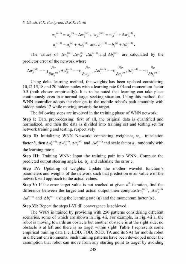
Using delta learning method, the weights has been updated considering 10,12,15,18 and 20 hidden nodes with a learning rate 0.01and momentum factor 0.5 (both chosen empirically). It is to be noted that learning can take place continuously even in a normal target seeking situation. Using this method, the WNN controller adopts the changes in the mobile robot’s path smoothly with hidden nodes 12 while moving towards the target.
The following steps are involved in the training phase of WNN network:
Step I: Data preprocessing: first of all, the original data is quantified and normalized, and then the data is divided into training set and testing set for network training and testing, respectively
Step II: Initializing WNN Network: connecting weights ,ij jkw w , translation
factor jb then ( 1) ( 1) ( 1) ( 1), , and i i i iij jk j jw w a b and scale factor ja randomly with
the learning rate η.
Step III: Training WNN: Input the training pair into WNN, Compute the predicted output steering angle i.e. n and calculate the error e.
Step IV: Updating of weights: Update the mother wavelet function’s parameters and weights of the network such that prediction error value e of the network will approach to the actual values.
Step V: If the error target value is not reached at given nth iteration, find the difference between the target and actual output then compute ( 1)i
ijw , ( 1)ijkw
( 1) ( 1) and i ij ja b using the learning rate (η) and the momentum factor ( ) .
Step VI: Repeat the steps I-VI till convergence is achieved.
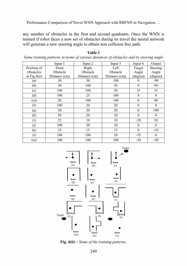
The WNN is trained by providing with 250 patterns considering different scenarios, some of which are shown in Fig. 4ii. For example, in Fig. 4ii a, the robot is moving towards an obstacle but another obstacle is at the right side; no obstacle is at left and there is no target within sight. Table 1 represents some empirical training data (i.e. LOD, FOD, ROD, TA and its SA) for mobile robot in different environments. Such training patterns have been developed under the assumption that robot can move from any starting point to target by avoiding
Performance Comparison of Novel WNN Approach with RBFNN in Navigation …
249
any number of obstacles in the first and second quadrants. Once the WNN is trained if robot faces a new set of obstacles during its travel the neural network will generate a new steering angle to obtain non collision free path.
Table 1 Some training patterns in terms of various distances of obstacles and its steering angle
Input 1 Input 2 Input 3 Input 4 Output Position of Obstacles in Fig.4(ii)
Front Obstacle
Distance (cm)
Right Obstacle
Distance (cm)
Left Obstacle
Distance (cm)
Target Angle
(degree)
Steering Angle
(degree) (a) 30 30 100 0 -90 (b) 30 100 30 0 90 (c) 100 100 30 35 35 (d) 100 25 100 0 0 (e)) 20 100 100 0 90 (f) 100 20 20 0 0 (g) 20 20 20 0 180 (h) 50 20 20 0 0 (i) 25 10 10 -20 10 (j) 100 20 20 0 0 (k) 25 15 15 0 -10 (l) 100 100 20 -35 0 (m) 100 100 100 -30 -30
Robot
(o)
Robot
(a) Robot
(b) Robot
(c)
Robot
(d) Robot
(e)
Robot
(f)
Robot
(g) Robot
(h) Robot
(i)
Robot
(m)Robot
(n)
Robot
(k) Robot
(j) Robot
(l)
Target
Target
Fig. 4(ii) Some of the training patterns.
S. Ghosh, P.K. Panigrahi, D.R.K. Parhi
250
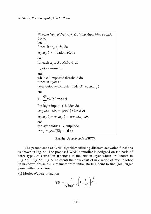
Fig. 5a Pseudo code of WNN.
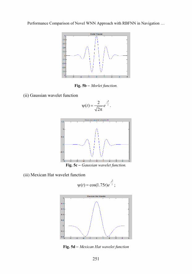
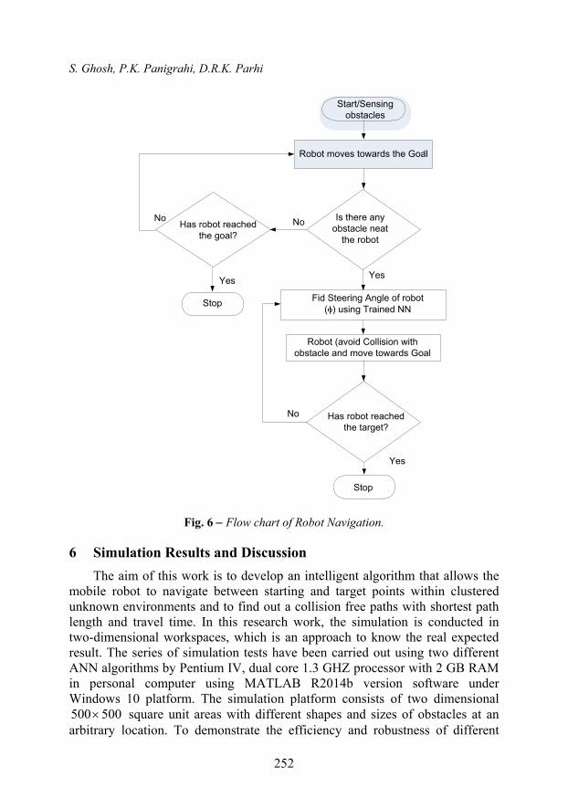
The pseudo code of WNN algorithm utilizing different activation functions is shown in Fig. 5a. The proposed WNN controller is designed on the basis of three types of activation functions in the hidden layer which are shown in Fig. 5b − Fig. 5d. Fig. 6 represents the flow chart of navigation of mobile robot in unknown obstacle environment from initial starting point to final goal/target point without collision.
(i) Morlet Wavelet Function
2
22
20.25
2( ) 1
3
ttt e
.
Wavelet Neural Network Training Algorithm Pseudo Code: begin for each , ,ij j jw a b do
, ,ij j jw a b random (0, 1)
end for each ,jx X ( )k do
, ( )jx k normalize
end while e > expected threshold do for each layer do layer output= compute (node, X, , ,ij j jw a b )
end
1
( ( ) ( ))m
ni
e k k
For layer input hidden do
, , Morlet ij j jw a b grad e
, , , , , ,ij j j ij j j ij j jw a b w a b w a b
end for layer hidden output do
(Sigmoid )jkw grad e
Performance Comparison of Novel WNN Approach with RBFNN in Navigation …
251
Fig. 5b Morlet function.
(ii) Gaussian wavelet function
2
22( )
2
t
t e
.
Fig. 5c Gaussian wavelet function.
(iii) Mexican Hat wavelet function
2
2
( ) cos(1.75 )t
t t e
;
Fig. 5d Mexican Hat wavelet function
S. Ghosh, P.K. Panigrahi, D.R.K. Parhi
252
Robot moves towards the Goal,
Start/Sensing obstacles
Stop
Yes
Is there any obstacle neat
the robot
Yes
Fid Steering Angle of robot ( ) using Trained NN
Robot (avoid Collision with obstacle and move towards Goal
Has robot reached the target?
No
No
Yes
Stop
Has robot reached the goal?
No
Fig. 6 Flow chart of Robot Navigation.
6 Simulation Results and Discussion
The aim of this work is to develop an intelligent algorithm that allows the mobile robot to navigate between starting and target points within clustered unknown environments and to find out a collision free paths with shortest path length and travel time. In this research work, the simulation is conducted in two-dimensional workspaces, which is an approach to know the real expected result. The series of simulation tests have been carried out using two different ANN algorithms by Pentium IV, dual core 1.3 GHZ processor with 2 GB RAM in personal computer using MATLAB R2014b version software under Windows 10 platform. The simulation platform consists of two dimensional 500 500 square unit areas with different shapes and sizes of obstacles at an arbitrary location. To demonstrate the efficiency and robustness of different
Performance Comparison of Novel WNN Approach with RBFNN in Navigation …
253
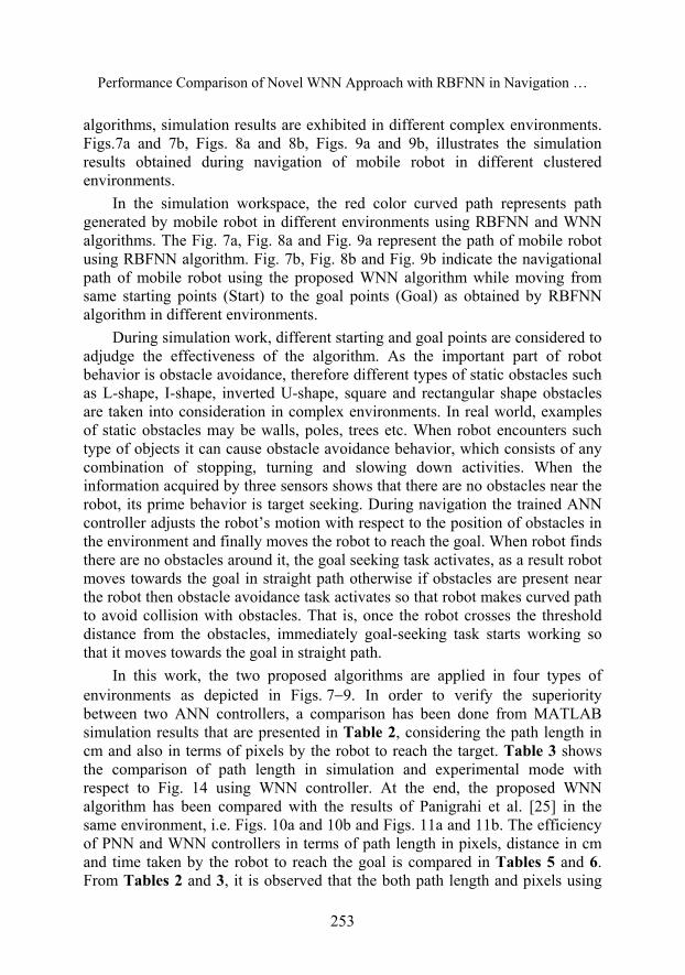
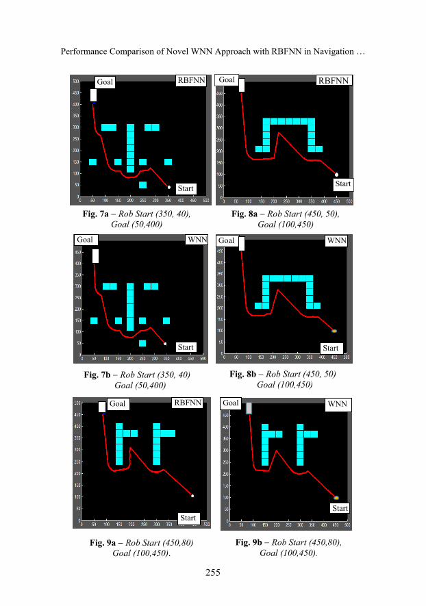
algorithms, simulation results are exhibited in different complex environments. Figs.7a and 7b, Figs. 8a and 8b, Figs. 9a and 9b, illustrates the simulation results obtained during navigation of mobile robot in different clustered environments.
In the simulation workspace, the red color curved path represents path generated by mobile robot in different environments using RBFNN and WNN algorithms. The Fig. 7a, Fig. 8a and Fig. 9a represent the path of mobile robot using RBFNN algorithm. Fig. 7b, Fig. 8b and Fig. 9b indicate the navigational path of mobile robot using the proposed WNN algorithm while moving from same starting points (Start) to the goal points (Goal) as obtained by RBFNN algorithm in different environments.
During simulation work, different starting and goal points are considered to adjudge the effectiveness of the algorithm. As the important part of robot behavior is obstacle avoidance, therefore different types of static obstacles such as L-shape, I-shape, inverted U-shape, square and rectangular shape obstacles are taken into consideration in complex environments. In real world, examples of static obstacles may be walls, poles, trees etc. When robot encounters such type of objects it can cause obstacle avoidance behavior, which consists of any combination of stopping, turning and slowing down activities. When the information acquired by three sensors shows that there are no obstacles near the robot, its prime behavior is target seeking. During navigation the trained ANN controller adjusts the robot’s motion with respect to the position of obstacles in the environment and finally moves the robot to reach the goal. When robot finds there are no obstacles around it, the goal seeking task activates, as a result robot moves towards the goal in straight path otherwise if obstacles are present near the robot then obstacle avoidance task activates so that robot makes curved path to avoid collision with obstacles. That is, once the robot crosses the threshold distance from the obstacles, immediately goal-seeking task starts working so that it moves towards the goal in straight path.
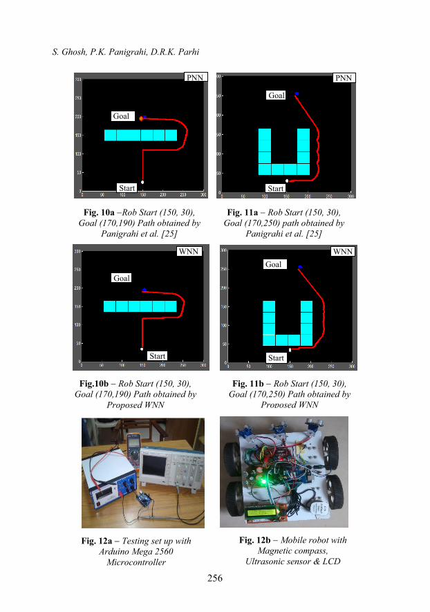
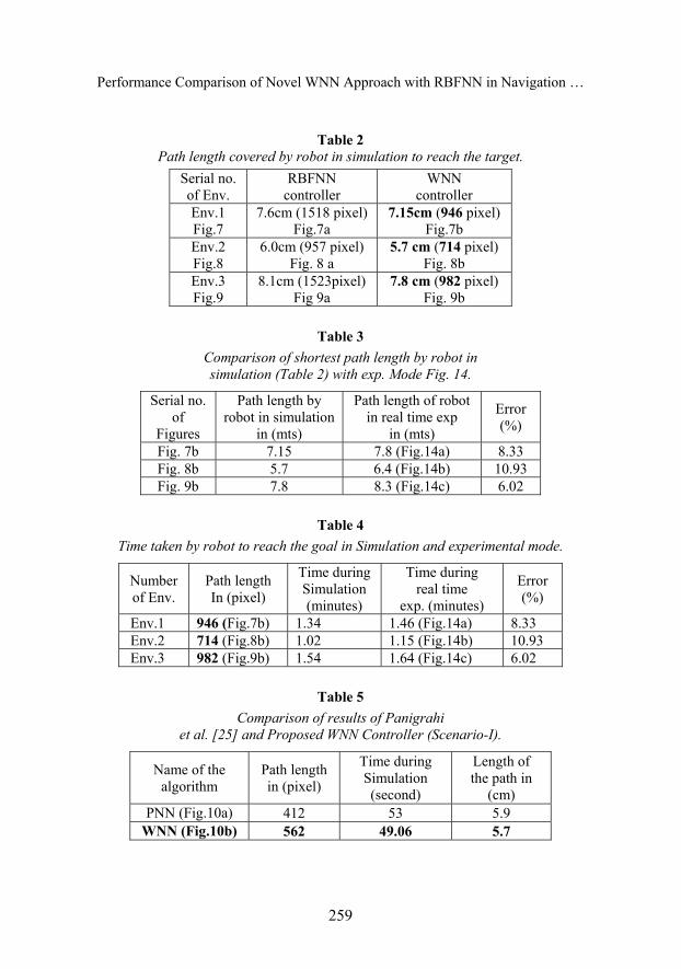
In this work, the two proposed algorithms are applied in four types of environments as depicted in Figs. 79. In order to verify the superiority between two ANN controllers, a comparison has been done from MATLAB simulation results that are presented in Table 2, considering the path length in cm and also in terms of pixels by the robot to reach the target. Table 3 shows the comparison of path length in simulation and experimental mode with respect to Fig. 14 using WNN controller. At the end, the proposed WNN algorithm has been compared with the results of Panigrahi et al. [25] in the same environment, i.e. Figs. 10a and 10b and Figs. 11a and 11b. The efficiency of PNN and WNN controllers in terms of path length in pixels, distance in cm and time taken by the robot to reach the goal is compared in Tables 5 and 6. From Tables 2 and 3, it is observed that the both path length and pixels using
S. Ghosh, P.K. Panigrahi, D.R.K. Parhi
254
WNN controller are less than the RBFNN controller. Moreover, from Tables 2 to 6 it may be concluded that the proposed WNN controller takes less time and makes shorter path length to reach the goal in the environments as shown in Figs. 7a and 7b, Figs. 8a and 8b, Figs. 9a and 9b, Figs. 10a and 10b and Figs. 11a and 11b. This comparison shows a good agreement.
7 Experimental Set Up
In order to validate the simulation results, an experimental analysis has been carried out by a differential driven mobile robot. The robot is equipped with the following accessories while performing the experiments in several real-time environments.
1. Fig. 12c represents the mobile robot’s accessories to make an autonomous mobile robot to fulfil our objective, where Arduino Mega 2560 is a Microcontroller board based on the ATmega2560. It consists of 54 input/output pins (of which 14 are used for PWM outputs), 16 analog inputs, 4 UARTs (hardware serial ports), a 16 MHz crystal oscillator, an USB connector, a power jack, an ICSP header and a reset button. Using Arduino command (program is prepared using C) and its functions each of the 54 digital pins of Microcontroller can be used as an input or output of a given task. Fig 12a and Fig 12b show the test set up of Arduino Mega 2560 and complete architecture of robot.
2. The robotic system using an Arduino Mega 2560 microcontroller is interfaced to a LCD, a magnetic compass sensor and two rear DC motors. The compass sensor determines the vehicle direction by continuously providing measurement of heading angle ( ) . The microcontroller drives the DC motors using motor driver to move the vehicle to the destination location by generating appropriate steering angle ( ) . Three ultrasonic sensors are utilized to carry out the obstacle detection and obstacle avoidance is achieved with the help of command from microcontroller.
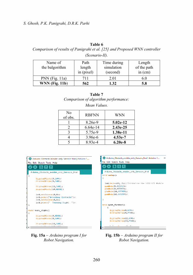
3. For autonomous navigation an Arduino 3 axis magnetic compass (HMC 5883L) is provided to measure the earth’s magnetic field in three axes. The 3-axis compass module measures field in thee directions labeled X, Y and Z. It is used to determine the direction of the robot. In experimental mode, the goal/destination location point coordinates are provided to the Arduino Mega 2560 microcontroller at beginning. Using Arduino codes (C-codes), the path-planning program has been prepared, and some of the programs are presented in the Fig.15a and 15b.
Performance Comparison of Novel WNN Approach with RBFNN in Navigation …
255
Start
WNN Goal
Start
Goal RBFNN
Start
Goal RBFNN
WNN Goal
Start
Fig. 7a Rob Start (350, 40), Goal (50,400)
Fig. 7b Rob Start (350, 40) Goal (50,400)
Fig. 8b Rob Start (450, 50) Goal (100,450)
Fig. 9a Rob Start (450,80) Goal (100,450).
Fig. 8a Rob Start (450, 50), Goal (100,450)
Fig. 9b Rob Start (450,80), Goal (100,450).
Goal WNN
Start Start
Goal RBFNN
S. Ghosh, P.K. Panigrahi, D.R.K. Parhi
256
Start
Goal
WNN
Start
Goal
WNN
Start
Goal
PNN PNN
Goal
Start
Fig. 10a Rob Start (150, 30), Goal (170,190) Path obtained by
Panigrahi et al. [25]
Fig.10b Rob Start (150, 30), Goal (170,190) Path obtained by
Proposed WNN
Fig. 11b Rob Start (150, 30), Goal (170,250) Path obtained by
Proposed WNN
Fig. 11a Rob Start (150, 30), Goal (170,250) path obtained by
Panigrahi et al. [25]
Fig. 12a Testing set up with Arduino Mega 2560
Microcontroller
Fig. 12b Mobile robot with Magnetic compass,
Ultrasonic sensor & LCD

Performance Comparison of Novel WNN Approach with RBFNN in Navigation …
257
Fig. 12c Mobile robot components.
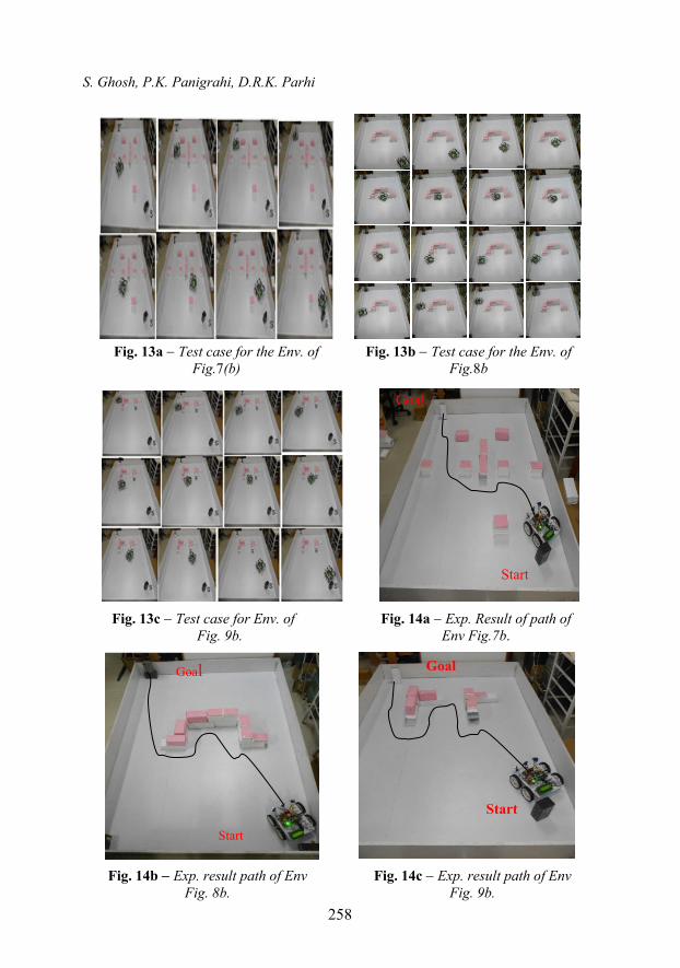
4. Ultrasonic sensors (HC-SR04) are used to detect the distance of the closest obstacle in left, front and right sectors of the sensor (from 2 m to 3 m). In experimental mode, the target location point coordinates are provided to the Arduino Mega 2560 micro controller at beginning. The robot is allowed to move from the same start point to target/goal as shown in Fig.7b, Fig. 8b and Fig. 9b using WNN during simulation. Figs. 14a14c represent the path obtained by robot in experimental mode using WNN algorithm applied in Arduino micro-controller. Figs. 13a 13c show snap shots of some positions of mobile robot in different environments during navigation. It is observed that the mobile robot has successfully navigated from starting point to target point making collision free path. Table 3 shows the results of path length in pixels and time to reach the target in seconds with simulation as well as experimental modes. It is observed that the proposed WNN controller algorithm makes lesser number of pixels and takes shorter time both during simulation and experimental work. After obtaining the above information, another comparison has also been made in terms of path length in simulation, experimental mode. Mean values of error are presented in Tables 3 and 7 to conclude the findings of this research work. It may be concluded that though the WNN controller makes shortest path length and takes lesser time in navigation but the experimental path length and time taken to reach the target were more than the simulation results. This may be due to the presence of signal transmission error in data cable, goal tracking error, frictional error in rotating elements, slippage between floor and wheels, friction between supported point and floor etc.).
4 Wheel Motor
LCD Display Motor Controller
Ultrasonic Sensor
Arduino Mega 2560 Microcontroller
Magnetic Compass
S. Ghosh, P.K. Panigrahi, D.R.K. Parhi
258
Start
Goal
Start
Goal
Goal
Start
Fig. 13a Test case for the Env. of Fig.7(b)
Fig. 13c Test case for Env. of Fig. 9b.
Fig. 14b Exp. result path of EnvFig. 8b.
Fig. 14c Exp. result path of Env Fig. 9b.
Fig. 14a Exp. Result of path of Env Fig.7b.
Fig. 13b Test case for the Env. of Fig.8b
Performance Comparison of Novel WNN Approach with RBFNN in Navigation …
259
Table 2
Path length covered by robot in simulation to reach the target. Serial no. of Env.
RBFNN controller
WNN controller
Env.1 Fig.7
7.6cm (1518 pixel) Fig.7a
7.15cm (946 pixel) Fig.7b
Env.2 Fig.8
6.0cm (957 pixel) Fig. 8 a
5.7 cm (714 pixel) Fig. 8b
Env.3 Fig.9
8.1cm (1523pixel) Fig 9a
7.8 cm (982 pixel) Fig. 9b
Table 3
Comparison of shortest path length by robot in simulation (Table 2) with exp. Mode Fig. 14.
Serial no. of
Figures
Path length by robot in simulation
in (mts)
Path length of robot in real time exp
in (mts)
Error (%)
Fig. 7b 7.15 7.8 (Fig.14a) 8.33 Fig. 8b 5.7 6.4 (Fig.14b) 10.93 Fig. 9b 7.8 8.3 (Fig.14c) 6.02
Table 4
Time taken by robot to reach the goal in Simulation and experimental mode.
Number of Env.
Path length In (pixel)
Time during Simulation (minutes)
Time during real time
exp. (minutes)
Error (%)
Env.1 946 (Fig.7b) 1.34 1.46 (Fig.14a) 8.33 Env.2 714 (Fig.8b) 1.02 1.15 (Fig.14b) 10.93 Env.3 982 (Fig.9b) 1.54 1.64 (Fig.14c) 6.02
Table 5
Comparison of results of Panigrahi et al. [25] and Proposed WNN Controller (Scenario-I).
Name of the algorithm
Path length in (pixel)
Time during Simulation (second)
Length of the path in
(cm) PNN (Fig.10a) 412 53 5.9
WNN (Fig.10b) 562 49.06 5.7
S. Ghosh, P.K. Panigrahi, D.R.K. Parhi
260
Table 6 Comparison of results of Panigrahi et al. [25] and Proposed WNN controller
(Scenario-II).
Name of the balgorithm
Path length
in (pixel)
Time during simulation (second)
Length of the path
in (cm)
PNN (Fig. 11a) 711 2.01 6.0 WNN (Fig. 11b) 562 1.32 5.8
Table 7
Comparison of algorithm performance:
Mean Values.
No of obs.
RBFNN WNN
1 8.26e-9 5.02e-12 2 6.64e-14 2.43e-25 3 5.75e-9 1.38e-11 4 3.96e-6 4.53e-7 5 8.93e-4 6.20e-8
Fig. 15a Arduino program I for Robot Navigation.
Fig. 15b Arduino program II for Robot Navigation.
Performance Comparison of Novel WNN Approach with RBFNN in Navigation …
261
8 Conclusion
There exist many ANN controllers for path planning of mobile robot in unknown environment containing static obstacles. In this work a WNN controller has been proposed and the effectiveness of the controller has been demonstrated through a variety of clustered environments in simulation as well as in experimental mode. Considering the results presented in this work it may be concluded that there are some advantages in using WNN instead of other two algorithms, because it is possible to achieve better solution in terms of collision free path, shortest path length and takes shortest time during navigation in unknown environments of different starting points to targets. Additionally, the proposed algorithm has been verified with the result of Panigrahi et al. [25]. The results of different simulations are also validated with experimental results using Arduino Mega 2560 microcontroller, which shows a good agreement to the path planning of mobile robot in unknown environment. Hence, the proposed WNN controller may be applied for the multi-robot path planning problems with static as well as dynamic obstacle environments in future work.
9 References
[1] D. Abiyev, D. Ibrahim, B. Erin: Navigation of Mobile Robots in the Presence of Obstacles, Advances in Engineering Software, Vol. 41, No. 10-11, Oct/Nov. 2010, pp. 1179 – 1186.
[2] S.M. Raghuraman, D. Tamilselvi, N. Shivakumar: Mobile Robot Navigation using Fuzzy Logic Controller, International Conference on Control, Automation, Communication and Energy Conversion, Perundurai, India, 04-06 June 2009.
[3] S.K. Harisha, K.P. Ramakantha, M. Krishna, S. Sharma: Fuzzy Logic Reasoning to Control Mobile Robot on a Pre-defined Strip-Path, World Academy of Science, Engineering and Technology, Vol. 42, 2008, pp. 642 – 646.
[4] Q.Y. Bao, L.I. S.M. Li, W.Y. Shang, M.J. An: A Fuzzy Behavior-Based Architecture for Mobile Robot Navigation in Unknown Environments, International Conference on Artificial Intelligence and Computational Intelligence, Shanghai, China, 07-08 Nov. 2009, Vol. 2, pp. 257 – 261.
[5] T. Lee, C.J. Wu: Fuzzy Motion Planning of Mobile Robots in Unknown Environments, International Journal of Intelligent and Robotics Systems, Vol. 37, No. 2, June 2003, pp. 177 – 191.
[6] O. Hachour: The Proposed Fuzzy Logic Navigation Approach of Autonomous Multi-robots in Unknown Environments, International Journal of Mathematical Models in Applied Sciences, Vol. 3, No. 3, 2009, pp. 204 – 218.
[7] T. Jin: Obstacle Avoidance of Mobile Robot Based on Behavior Hierarchy by Fuzzy Logic, International Journal of Fuzzy Logic and Intelligent Systems, Vol. 12, No. 3, Sept. 2012, pp. 245 – 249.
[8] P.K. Panigrahi, S. Ghosh, D.R Parhi: A Comparison of Mamdani and Sugeno Based Fuzzy Controller for Mobile Robot to Avoid Static Obstacles, 5th International Conference on Electronics and Computer Science, Kolkata, India, 28-29 Aug. 2014, p. 89.
S. Ghosh, P.K. Panigrahi, D.R.K. Parhi
262
[9] M.M Joshi, M.K Zaveri: Optimally Learnt Neural Network based Autonomous Mobile Robot Navigation System, International Journal on Control System and Instrumentation, Vol. 2, No. 1, Feb. 2011, pp. 28 – 32.
[10] D. Janglova: Neural Networks in Mobile Robot Motion, International Journal of Advanced Robotics Systems, Vol. 1, No. 1, Nov. 2004, pp. 15 – 22.
[11] P.K. Panigrahi, S. Ghosh, D.R. Parhi: Navigation of Autonomous Mobile Robot Using Different Activation Functions of Wavelet Neural Network, Archives of Control Sciences, Vol. 25, No. 1, 2015, pp. 21 – 34.
[12] D.Z. Jiang, W.Z. Min: Mobile Robot Path Tracking in Unknown Environment, IEEE Conference in Robotics, Automation and Mechatronics, Chengdu, China, 21-24 Sept. 2008, pp. 1201 – 1205.
[13] P.K. Panigrahi, S. Ghosh, D.R. Parhi: Intelligent Leaning and Control of Autonomous Mobile Robot using MLP and RBF based Neural Network in Clustered Environment, International Journal of Scientific and Engineering Research, Vol. 5, No. 6, June 2014, pp. 313 – 316.
[14] A.A. Baker: A Novel Mobile Robot Navigation System Using Neuro-Fuzzy Rule-based Optimization Technique, Journal of Applied Sciences and Technology, Vol. 4, No. 15, 2012, pp. 2577 – 2583.
[15] Y. Gigras, K. Gupta: Artificial Intelligence in Robot Path Planning, International Journal of Soft Computing and Engineering, Vol. 2, No. 2, May 2012, pp. 471 – 474.
[16] V. Castro, J.P. Neira, C.L. Rueda, J.C. Villamizar, L. Angel: Autonomous Navigation Strategies for Mobile Robots using a Probabilistic Neural Network, 33rd Annual Conference of the IEEE Industrial Electronics Society, Taipei, Taiwan, 05-08 Nov. 2007, pp. 2795 – 2800.
[17] N. Buniyamin, W.A.J. Wanngah, N. Sariff, Z. Mohamad: A Simple Local Path Planning Algorithm for Autonomous Mobile Robots, International Journal of Systems Applications, Engineering and Development, Vol. 5, No. 2, 2011, pp. 151 – 159.
[18] S.X. Yang, M.Q.H. Meng: Real-Time Collision-Free Motion Planning of a Mobile Robot using a Neural Dynamics-based Approach, IEEE Transaction on Neural Network, Vol. 14, No. 6, Nov. 2003, pp. 1541 – 1552.
[19] D. Braganza, M. Dawson, I.D. Walker, N. Nath: A Neural Network Controller for Continuum Robots, IEEE Transactions on Robotics, Vol. 23, No. 6, Dec. 2007, pp. 1270 – 1277.
[20] M.K. Singh, D.R. Parhi: Intelligent Neuro-controller for Navigation of Mobile Robot, International Conference on Advances in Computing, Communication and Control, Mumbai, India, 23-24 Jan. 2009, pp. 123 – 128.
[21] T. Kondo: Evolutionary Design and Behavior Analysis of Neuromodulary Neural Networks for Mobile Robots Control, Applied Soft Computing, Vol. 7, No. 1, Jan. 2007, pp. 189 – 202.
[22] M.L. Corradini, G. Ippoliti, S. Longhi: Neural Networks Based Control of Mobile Robots: Development and Experimental Validation, Journal of Robotic Systems, Vol. 20, No. 10, Oct. 2003, pp. 587 – 600.
[23] M.J. Er, Y. Zhou: Automatic Generation of Fuzzy Inference Systems via Unsupervised Learning, Neural Networks, Vol. 21, No. 10, Dec. 2008, pp. 1556 – 1566.
[24] Q. Zhang, J. Shippen, B. Jones: Robust Backstepping and Neural Network Control of a Low-quality Nonholonomic Mobile Robot, International Journal of Machines Tools Manufacturing, Vol. 39, No. 7, July 1999, pp. 1117 – 1134.
[25] P.K. Panigrahi, S. Ghosh, D.R. Parhi: A Novel Intelligent Mobile Robot Navigation Technique for Avoiding Obstacles using Probabilistic Neural Network (PNN), International Conference on Engineering and Applied Science, Hong Kong, 19-21 Dec. 2013, pp. 256 – 262.
Performance Comparison of Novel WNN Approach with RBFNN in Navigation …
263
[26] J. Velagic, N. Osmic, B. Lacevic: Neural Network Controller for Mobile Robot Motion Control, International Journal of Electrical and Computer Engineering, Vol. 3, 2008, pp. 127 – 132.
[27] S. Nefti, M. Oussalah, K. Djouaniand, J. Pontnau: Intelligent Adaptive Mobile Robot Navigation, Journal of Intelligent and Robotic Systems, Vol. 30, No. 4, April 2001, pp. 311 – 329.
[28] A. Sanchis, P. Isasi, J. M. Molina, J. Segovia: Applying Classifying Systems to Learn the Reactions in Mobile Robots, International Journal of Systems Science, Vol. 32, No. 2, 2001, pp. 237 – 258.
[29] J. Racz, A. Dubrawski: Artificial Neural Network for Mobile Robot Topological Localization, Robotics and Autonomous Systems, Vol. 16, No. 1, Nov. 1995, pp. 73 – 80.
[30] G. Oriolo, S. Panzieri, G. Ulivi: Learning Optimal Trajectories for Non-Holonomic Systems, International Journal of Control, Vol. 73, No. 10, 2000, pp. 980 – 991.