Embed Size (px)
Citation preview
Performance Bounds in In-Car and Aeronautic Networks
Seite 1
Hyung-Taek Lim (BMW), Emanuel Heidinger (EADS)

Outline
Introduction
• Motivation of Ethernet-based In-Car Networks
• Motivation of Ethernet-based Aeronautic Networks
Scope of the work and Techniques
• Discrete Event Simulation
Seite 2Emanuel Heidinger (EADS), Hyung-Taek Lim (BMW)
• Network Calculus
Performance Bounds and Evaluation
• Avionic Network
• In-Car Network with
- IEEE 802.1Q – Prioritization mechanism
- IEEE 802.1 Ethernet AVB
Summary, Conclusion

Motivation of Ethernet-based In-Car Networks
Vision and Challenges
Internet Protocol (IP)-based NetworkReplacement of current specific In-Car/Aeronautic protocols by standard IP
Seite 3Emanuel Heidinger (EADS), Hyung-Taek Lim (BMW)
• Suitable technology to transport IP for the industrial use
� Future applications have higher bandwidth demand
• Which of the existent technologies are capable to transport IP and can
fulfill the high bandwidth demand of future applications ?
� Ethernet ??

Legacy Ethernet
Applications
IP
TCP / UDP
7: Application
6: Presentation
5: Session
4: Transport
3: Network
?
?
?
(+) Mature Technology
(+) Fast, easy to use
(+) Two-wire unshielded available for automotive use
(+) No single source
(-) Real-time data transmission is not supported
Seite 4Emanuel Heidinger (EADS), Hyung-Taek Lim (BMW)
Ethernet Phy
Ethernet MAC 2: Data Link
1: Physical
supported
(-) Packets can be delayed or lost (Switch)
(-) Efficiency problems with small packets
Ethernet is currently used only for two areas in a vehicle:
● Diagnosis and flashing (OBD)
● Remote disc access
Currently: Ethernet is only used as a direct link without prioritization mechanism
Future: More than 2 ECUs are connected to the Ethernet network

State of the art:Avionics Full DupleX (AFDX):
• 100 ++ Endsystems; 10 ++ Switches
Ethernet in Aeronautic Networks
Seite 5
Additionally used technologies:•LVDS, CAN, ARINC 429, RS232, 10Base2 Ethernet, FlexRayVision: Build up Cabin System by COTS Components; homogeneous end-to-end networksVision 2025: Integrate In-Flight Entertainment in same network => Validation of high level requirements
[1]
[1]
Emanuel Heidinger (EADS), Hyung-Taek Lim (BMW)
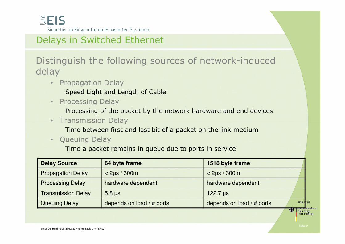
Delays in Switched Ethernet
Distinguish the following sources of network-induced delay
• Propagation Delay
Speed Light and Length of Cable
• Processing Delay
Processing of the packet by the network hardware and end devices
• Transmission Delay
Seite 6Emanuel Heidinger (EADS), Hyung-Taek Lim (BMW)
• Transmission Delay
Time between first and last bit of a packet on the link medium
• Queuing Delay
Time a packet remains in queue due to ports in service
Delay Source 64 byte frame 1518 byte frame
Propagation Delay < 2µs / 300m < 2µs / 300m
Processing Delay hardware dependent hardware dependent
Transmission Delay 5.8 µs 122.7 µs
Queuing Delay depends on load / # ports depends on load / # ports

Scope of the work and Methodology
• Analysis of an In-Car/Aeronautic Network with typical applications
- Influence of the
(1) Topology
(2) QoS mechanisms:
- Prioritization as specified in IEEE 802.1Q
- IEEE 802.1 AVB mechanisms
- Verifying the provided application constraints in terms of maximum end-to-end
delays
Seite 7Emanuel Heidinger (EADS), Hyung-Taek Lim (BMW)
delays
Worst Case Analysis
- Deterministic Network
Calculus (DNC)
Simulation-based Analysis
- Network Simulation with
INET-framework and some
modifications to support:
(1) Loading external trace files
(e.g. CAN, FlexRay traces)
(2) Prioritization mechanisms
(3) IEEE 802.1 Ethernet AVB

Deterministic Network Calculus – Short Introduction
–Arrival Curve α (1.6 MBit/s, burst 200 bytes)
– Service Curve β (3.2 MBit/s, delay 200 ms)
–Horizontal Deviation gives worst case Delay
–Vertical Deviation gives Backlogs
–Simple Example withone flow and one service curve
– For tight bounds it will be
Seite 8
– For tight bounds it will becrucial to find a tight servicecurve
Algorithms
– Total Flow Analysis (TFA)
–Separated Flow Analysis (SFA)
Emanuel Heidinger (EADS), Hyung-Taek Lim (BMW)

Cabin Scenario
Functionalities in Aircraft Cabin
• Passenger Call (PAX Call)
• Integrated Pre-recorded Announcement & Boarding Music
• Cabin Interphone
• Passenger Address (PA)
• Cabin Illumination
• Cabin Video Monitoring System
Seite 9Emanuel Heidinger (EADS), Hyung-Taek Lim (BMW)
• Cabin Video Monitoring System
Topology
• Star
• Up to 16 lines (more are welcome)
• Up to 12 BACs per line (more are welcome)
Prioritization
• IEEE 802.1Q
• high prio traffic, safety relevant
• low prio traffic, IFE as games, multimedia, etc.
[2]

Worst Case Simulation vs. Network Calculus, Cabin
Validation of high level requirements
• Low Delay
• Low Multicast Delay Difference
• Low Frame Loss
⇒Deterministic Network Calculus
⇒Network Simulation
⇒10 ms maximum delay
⇒100 ms maximum signaling delay
⇒1ms maximum multicast delay diff
⇒Worst Case Backlog
Network Calculus, 1-3
Seite 10Emanuel Heidinger (EADS), Hyung-Taek Lim (BMW)
Device Traffic Burst [bytes]
Rate [bytes/ms]
Peak [bytes/ms]
Sustain
[bytes]
Server TokenBucket 108 3456
PSU TokenBucket 108 25.5
Handset Dual
TokenBucket
64 204 816 1000
Disturb (optional)
TokenBucket 1518 6250
Traffic Description
Network Calculus, 1-3
Simulation, 1-4

Worst Case Simulation vs. Network Calculus, Cabin
• Worst Case Delay of each flow, staircase shows number of hops
• NC bound (blue/black) is worst case as identified by total flow analysis
• Worst case in light traffic
Seite 11Emanuel Heidinger (EADS), Hyung-Taek Lim (BMW)
• Worst case in light traffic scenario as identified by simulation (o)
• Worst case in overload scenario as identified by simulation (+)[3]
⇒10ms max delay and 100ms signalling delay are fulfilled
⇒1ms multicast delay difference could only be fulfilled with smaller MTU for high prio traffic

Simulation CDF, Device to Server
Validation of high level requirements
• Signaling is lower than 10ms
Requirement 100ms
• Audio Delay from handset to server is lower than 2ms
Requirement 10ms
Seite 12Emanuel Heidinger (EADS), Hyung-Taek Lim (BMW)

Switched Ethernet based In-Car Network [*]
DA_CAM
Control
Multimedia
Disc
Switch1
Switch1
DA_CAM
Control
Multimedia
Disc Changer
Seite 13Emanuel Heidinger (EADS), Hyung-Taek Lim (BMW)
Star-based(Topology-1)
Daisy chain-based(Topology-2)
Tree-based(Topology-3)
[*] Work was presented at the 48th Design Automation Conference (DAC 2011) Conference, San Diego
Head Unit
Legend:
ECU (End-Node)
Switch
100Mbit/s Link
Switch2
Switch3
RSE
Amplifier
TV
Control
Processing
Unit
AmplifierRSE
TV
Head Unit
Legend:
ECU (End-Node)
Switch
100Mbit/s Link

Traffic Type
UDP Packet Length [Byte]
SendingRate[ms]
Bandwidth[Mbit/s]
Prio Max.End-to-EndDelay [ms]
Control 18 33 < 1 3 10 [4,5]
DriverAssistanceCAM
1400 0.481 24 2 45 [5]
Navigation 1000 100 16 1 100
In-Car Network: Traffic Characteristics
Seite 14
MM Video 1400 0.28 41 0 150
MM Audio 1400 1.4 8.3 0 150
TV Video 1400 0.577 20 0 150
TV Audio 1400 2.33 4.9 0 150
Emanuel Heidinger (EADS), Hyung-Taek Lim (BMW)

Intermediate Result-1
(1) CDF: End-to-End delay Service constraints: - CTRL: Delay ≤ 10 ms- CAM: Delay ≤ 45 ms
Top-1 (‚star-based‘)Top-2 (‚daisy-chain‘)
Seite 15Emanuel Heidinger (EADS), Hyung-Taek Lim (BMW)
Top-3 (‚Tree-based‘)
Prioritization reduces the end-to-end delay of the highest data class to approx. 69%
Independent of the used Topology,Prioritization reduces the end-to-end delay of driver assistance camera data to approx. less than 10%

Intermediate Result-2: Worst-Case Analysis
- Performance Comparision:
End d
elay [m
s]
Seite 16Emanuel Heidinger (EADS), Hyung-Taek Lim (BMW)
- worst case calculation gives the hard limit for the end-to-end delay
Control CAM NAV MM-V MM-A TV-V TV-A
End-to-E
nd d
elay [m
s]

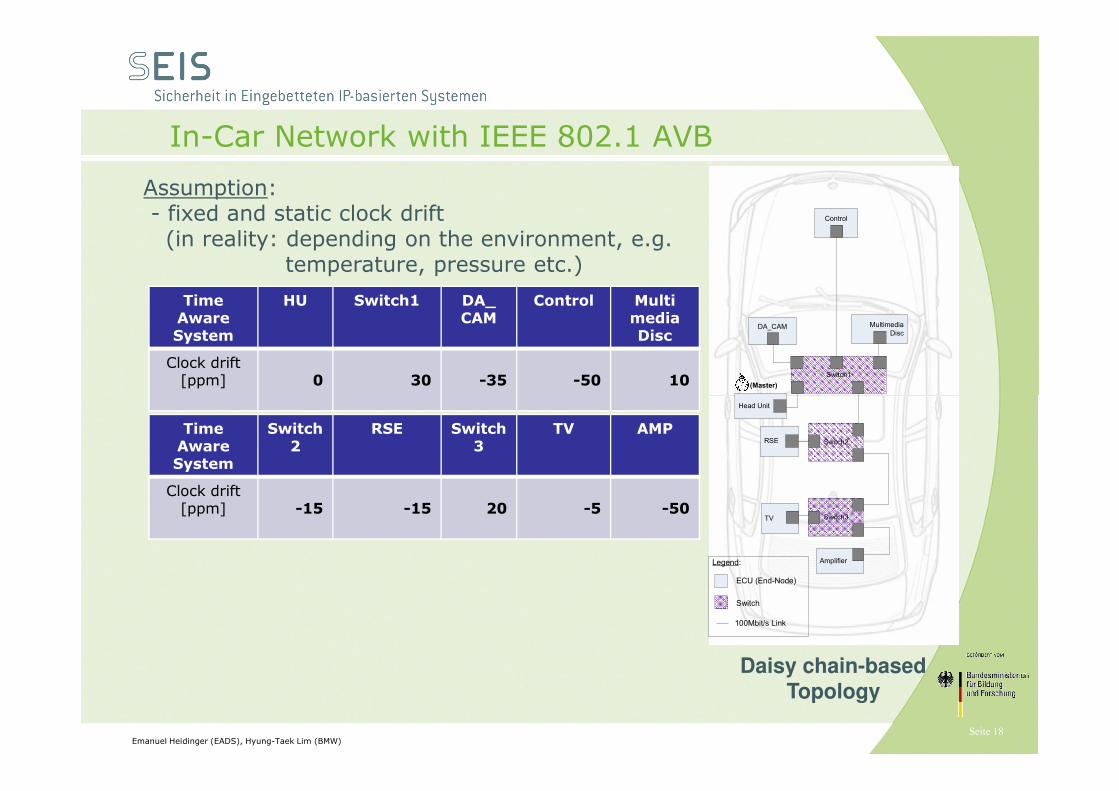
In-Car Network with IEEE 802.1 AVB
DA_CAM
Control
Multimedia
Disc
Switch1
(Master)
Following IEEE 802.1 AVB protocols are used for the performance evaluation:
� IEEE 802.1AS: Time Synchronization protocol
� IEEE 802.1Qat: Ressource Reservation protocolfor AVB streaming data
� IEEE 802.1Qav: Queuing and Forwarding rules for AVB streaming data
(1)
(2)
Seite 17Emanuel Heidinger (EADS), Hyung-Taek Lim (BMW)
Head Unit
Legend:
ECU (End-Node)
Switch
100Mbit/s Link
Switch2
Switch3
RSE
Amplifier
TV
Daisy chain-basedTopology
for AVB streaming data
� IEEE 1722: Transport protocol at Layer-2
Traffic Characteristics for AVB data:
TrafficType
AVBClass
FrameSize [byte]
Rate[ms]
BW[Mbit/s]
DAStream (1)
A 390 0.125 ≈ 27.6
TVStream (2)
B 800 0.250 ≈ 26.9
MMStream (3)
B 800 0.125 ≈ 53.8
(2)
(3)
In-Car Network with IEEE 802.1 AVB
DA_CAM
Control
Multimedia
Disc
Switch1
(Master)
Assumption:- fixed and static clock drift(in reality: depending on the environment, e.g.
temperature, pressure etc.)
Time AwareSystem
HU Switch1 DA_CAM
Control Multi mediaDisc
Clock drift[ppm] 0 30 -35 -50 10
Seite 18Emanuel Heidinger (EADS), Hyung-Taek Lim (BMW)
Head Unit
Legend:
ECU (End-Node)
Switch
100Mbit/s Link
Switch2
Switch3
RSE
Amplifier
TV
Daisy chain-basedTopology
Time AwareSystem
Switch2
RSE Switch3
TV AMP
Clock drift[ppm] -15 -15 20 -5 -50

Simulation Result
1.End-to-End delay 2. Synchronization accuracy
settling time (tset): 1.17 ms
Seite 19Emanuel Heidinger (EADS), Hyung-Taek Lim (BMW)
The end-to-end delays of MM-Streaming Data (AVB-Class B) are less than the maximum allowed latency.
After the listeners are synchronized (t>tset), the presentation time of the listeners are the same; no quite differences

Summary and Conclusion
- A switched Ethernet based In-Car/Aeronautic network was analyzed by determining the influence of:
(1) Topology(2) Prioritization mechanism as specified in IEEE 802.1Q
- A switched Ethernet based In-Car network with IEEE 802.1 AVB was analyzed to determine
(1) the latency of AVB streaming data(2) the synchronization process
Seite 20Emanuel Heidinger (EADS), Hyung-Taek Lim (BMW)
- Analysis was performed by(1) Simulation(2) Worst case estimation with determinitic network calculus
- Prioritization mechanisms can considerably improve the performance in terms of end-to-end delays and packet loss
- Ethernet AVB enables to synchronize different nodes with low latency after a certain time
- Worst case calculation with DNC gives information about the hard limit of end-to-end delays� DNC model has to be optimized to increase the accuracy

References
[1] Airbus, Internal Documents[2] Heidinger, E.; Heller, C.; Klein, A. & Schneele, S. Quality of Service IP Cabin Infrastructure Digital Avionics Systems Conference (DASC), 2010 IEEE/AIAA 29th, , 3-D[3] Heidinger, E. Rarer Events in Network Simulation Using MIP ITC, 2011[4] R. Steffen, R. Bogenberger, M. Rahmani, J. Hillebrand, W. Hintermaier, and A. Winckler, Design and Realization of an IP-based In-Car Network Architecture, The First Annual International Symposium on Vehicular Computing Systems, Dublin, July 2008.[5] M. Rahmani, R. Steen, K. Tappayuthpijarn, G. Giordano, R. Bogenberger, and E. Steinbach, Performance Analysis of Different Network Topologies for In-Vehicle Audio and Video Communication, The 4th International Telecommunication Networking WorkShop on QoS in Multiservice IP Networks(QoS-IP 2008), Venice, Italy, Feb 2008.
Seite 21Emanuel Heidinger (EADS), Hyung-Taek Lim (BMW)