Embed Size (px)
Citation preview
One Week FDPFundamentals of Structural Dynamics and Application to
Earthquake Engineeringin Sanjay Ghodawat Group of Institute
Performance-Based Plastic Design Method
Dr. Swapnil B. Kharmale
Assistant Professor, Applied MechanicsGovernment College of Engineering and Research, Avasari
December 11, 2015Dr. Swapnil B. Kharmale Fundamentals of Structural Dynamics and Application to Earthquake Engineering
Content
1 Review of Current Seismic Design Procedure
Design Standards (Viz IS 1893, ASCE7)
Calculation of Base Shear Vb
Response reduction or modification factor R
Equivalent Static Lateral Force Distribution
Design of members of LLRS
Displacement ductility of LLRS µ
2 Weaknesses in Current Seismic Design Procedure
3 Perfomance-Based Seismic Design (PBSD)
4 Performance-Based Plastic Design (PBPD)
Basis of Design Method
Application of PBPD to Various LLRS
PBPD for Steel MRF by Lee and Goel (2001)
Dr. Swapnil B. Kharmale Fundamentals of Structural Dynamics and Application to Earthquake Engineering
Review of Current Seismic Design Procedure
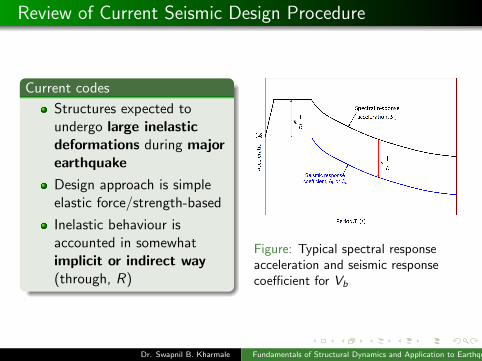
Current codes
Structures expected toundergo large inelasticdeformations during majorearthquake
Design approach is simpleelastic force/strength-based
Inelastic behaviour isaccounted in somewhatimplicit or indirect way(through, R)
Figure: Typical spectral responseacceleration and seismic responsecoefficient for Vb
Dr. Swapnil B. Kharmale Fundamentals of Structural Dynamics and Application to Earthquake Engineering
Review of Current Seismic Design Procedure: Calculationof Vb
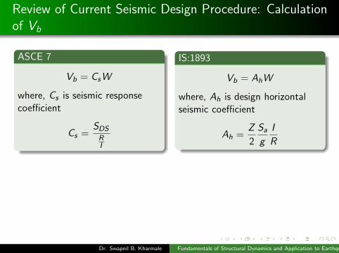
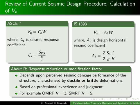
ASCE 7
Vb = CsW
where, Cs is seismic responsecoefficient
Cs =SDSRI
IS:1893
Vb = AhW
where, Ah is design horizontalseismic coefficient
Ah =Z
2
Sag
I
R
About R: Response reduction or modification factor
Depends upon perceived seismic damage performance of thestructure, characterised by ductile or brittle deformations.
Based on professional experience and judgment.
For example OMRF R = 3, SMRF R = 5.
Dr. Swapnil B. Kharmale Fundamentals of Structural Dynamics and Application to Earthquake Engineering
Review of Current Seismic Design Procedure: Calculationof Vb
ASCE 7
Vb = CsW
where, Cs is seismic responsecoefficient
Cs =SDSRI
IS:1893
Vb = AhW
where, Ah is design horizontalseismic coefficient
Ah =Z
2
Sag
I
R
About R: Response reduction or modification factor
Depends upon perceived seismic damage performance of thestructure, characterised by ductile or brittle deformations.
Based on professional experience and judgment.
For example OMRF R = 3, SMRF R = 5.
Dr. Swapnil B. Kharmale Fundamentals of Structural Dynamics and Application to Earthquake Engineering
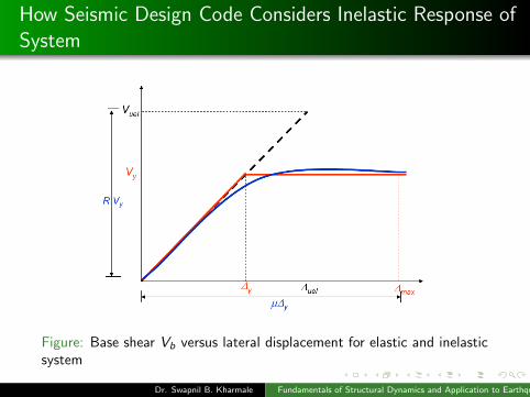
How Seismic Design Code Considers Inelastic Response ofSystem
Figure: Base shear Vb versus lateral displacement for elastic and inelasticsystem
Dr. Swapnil B. Kharmale Fundamentals of Structural Dynamics and Application to Earthquake Engineering
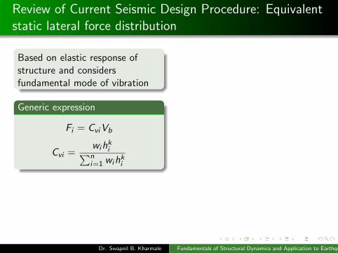
Review of Current Seismic Design Procedure: Equivalentstatic lateral force distribution
Based on elastic response ofstructure and considersfundamental mode of vibration
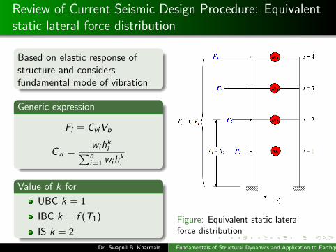
Generic expression
Fi = CviVb
Cvi =wih
ki∑n
i=1 wihki
Value of k for
UBC k = 1
IBC k = f (T1)
IS k = 2Figure: Equivalent static lateralforce distribution
Dr. Swapnil B. Kharmale Fundamentals of Structural Dynamics and Application to Earthquake Engineering
Review of Current Seismic Design Procedure: Equivalentstatic lateral force distribution
Based on elastic response ofstructure and considersfundamental mode of vibration
Generic expression
Fi = CviVb
Cvi =wih
ki∑n
i=1 wihki
Value of k for
UBC k = 1
IBC k = f (T1)
IS k = 2Figure: Equivalent static lateralforce distribution
Dr. Swapnil B. Kharmale Fundamentals of Structural Dynamics and Application to Earthquake Engineering
Review of Current Seismic Design Procedure: Selection ofmember sizes
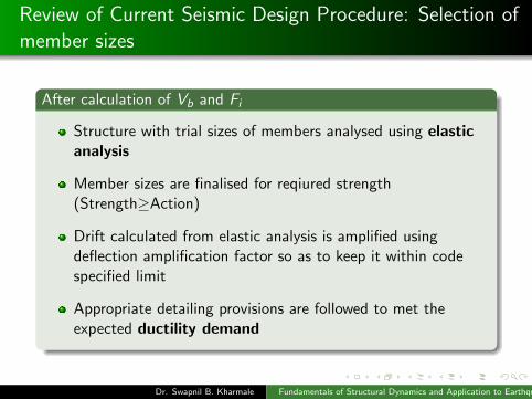
After calculation of Vb and Fi
Structure with trial sizes of members analysed using elasticanalysis
Member sizes are finalised for reqiured strength(Strength≥Action)
Drift calculated from elastic analysis is amplified usingdeflection amplification factor so as to keep it within codespecified limit
Appropriate detailing provisions are followed to met theexpected ductility demand
Dr. Swapnil B. Kharmale Fundamentals of Structural Dynamics and Application to Earthquake Engineering
Review of Current Seismic Design Procedure:Displacement ductility µ
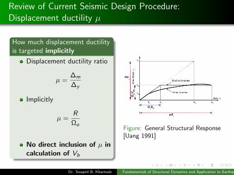
How much displacement ductilityis targeted implicitly
Displacement ductility ratio
µ =∆m
∆y
Implicitly
µ =R
Ωo
No direct inclusion of µ incalculation of Vb
Figure: General Structural Response[Uang 1991]
Dr. Swapnil B. Kharmale Fundamentals of Structural Dynamics and Application to Earthquake Engineering
Review of Current Seismic Design Procedure:Displacement ductility µ
How much displacement ductilityis targeted implicitly
Displacement ductility ratio
µ =∆m
∆y
Implicitly
µ =R
Ωo
No direct inclusion of µ incalculation of Vb
Figure: General Structural Response[Uang 1991]
Dr. Swapnil B. Kharmale Fundamentals of Structural Dynamics and Application to Earthquake Engineering
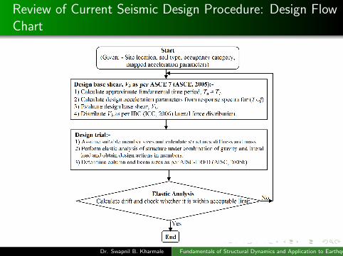
Review of Current Seismic Design Procedure: Design FlowChart
Figure: Typical design flow chart of current seismic design procedure(Say ASCE7)
Dr. Swapnil B. Kharmale Fundamentals of Structural Dynamics and Application to Earthquake Engineering
Review of Current Seismic Design Procedure: Weaknessesin design procedure
Force/strength-based and not displacement-based asdisplacements/drifts are better measure of damages
More iterative and never provide good or optimal design asdesired
Current design procedure is unable to utilize the significantinelastic deformation capacity of system
Structure designed by current design procedure whensubjected to severe strong motion have been found to undergolarge inelastic deformation in “un-controlled manner” (Say“soft storey” an unlike collapse mechanism)
Dr. Swapnil B. Kharmale Fundamentals of Structural Dynamics and Application to Earthquake Engineering
Performance-Based Seismic Design (PBSD)
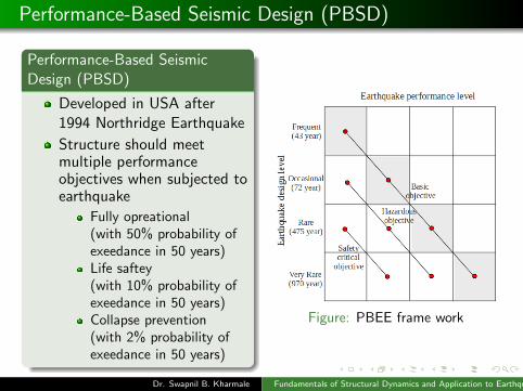
Performance-Based SeismicDesign (PBSD)
Developed in USA after1994 Northridge Earthquake
Structure should meetmultiple performanceobjectives when subjected toearthquake
Fully opreational(with 50% probability ofexeedance in 50 years)Life saftey(with 10% probability ofexeedance in 50 years)Collapse prevention(with 2% probability ofexeedance in 50 years)
Figure: PBEE frame work
Dr. Swapnil B. Kharmale Fundamentals of Structural Dynamics and Application to Earthquake Engineering
Salient features of PBSD
PBEE allows to choose owner or designer
level of ground shaking
level of performance/protection for that ground motion
Hence abvantages of PBSD
Better characterization of structural damage and dueconsideration to uncertainties
Explicit (Direct) consideration to inelastic behaviour in thedesign
Dr. Swapnil B. Kharmale Fundamentals of Structural Dynamics and Application to Earthquake Engineering
Appraches in PBSD
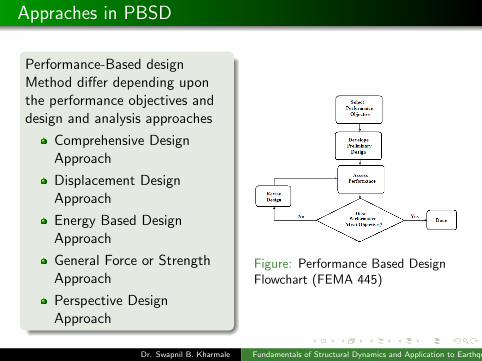
Performance-Based designMethod differ depending uponthe performance objectives anddesign and analysis approaches
Comprehensive DesignApproach
Displacement DesignApproach
Energy Based DesignApproach
General Force or StrengthApproach
Perspective DesignApproach
Figure: Performance Based DesignFlowchart (FEMA 445)
Dr. Swapnil B. Kharmale Fundamentals of Structural Dynamics and Application to Earthquake Engineering

Performance-Based Plastic Design (PBPD) Method
Developed at University of Michigan by Prof. Goel andResearch Associates
PBSD approaches based on plastic analysis and designconcepts
Pre-selected yield/failure mechanism and a uniformtarget drift (based on inelastic behaviour) are considered asperformance objectives.
Accounts for structural inelastic behaviour directly
Practically eliminate the need for assesment or iteration afterinitial design
Seismic force calculations are based on the concept ofenergy balance
Dr. Swapnil B. Kharmale Fundamentals of Structural Dynamics and Application to Earthquake Engineering
Performance-Based Plastic Design (PBPD) Method: Basisof Design
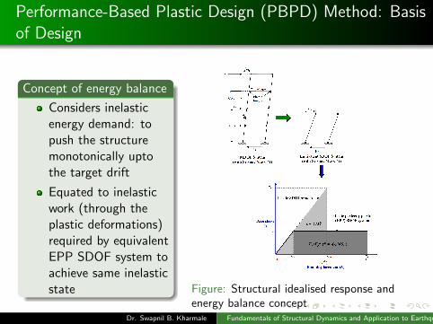
Concept of energy balance
Considers inelasticenergy demand: topush the structuremonotonically uptothe target drift
Equated to inelasticwork (through theplastic deformations)required by equivalentEPP SDOF system toachieve same inelasticstate Figure: Structural idealised response and
energy balance conceptDr. Swapnil B. Kharmale Fundamentals of Structural Dynamics and Application to Earthquake Engineering
Performance-Based Plastic Design (PBPD) Method:Application to various system
Application to various lateral load resisting system
Steel MRF: Leelataviwat et al. (1999) and Lee and Goel(2001)
Steel Buckling Restrained Braced frame: Dasgupta et al.(2005)
Steel Braced frame: Chao and Goel (2005)
Steel Special Truss Moment Resisting Frames: Chao andGoel (2008)
Steel Plate Shear Walls: Ghosh et al. (2009) and Kharmale(2011)
Dr. Swapnil B. Kharmale Fundamentals of Structural Dynamics and Application to Earthquake Engineering
PBPD for Steel MRF by Lee and Goel (2001)
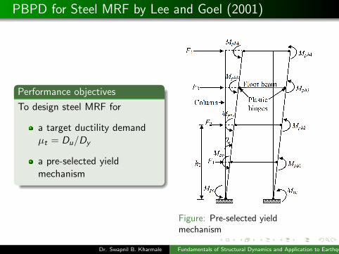
Performance objectives
To design steel MRF for
a target ductility demandµt = Du/Dy
a pre-selected yieldmechanism
Figure: Pre-selected yieldmechanism
Dr. Swapnil B. Kharmale Fundamentals of Structural Dynamics and Application to Earthquake Engineering
PBPD for Steel MRF : Design yield base shear Vby
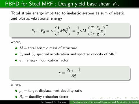
Total strain energy imparted to inelastic system as sum of elasticand plastic vibrational energy
Ee + Ep = γ
(1
2MS2
v
)=
1
2γM
(T1
2π
Sagg
)2
where,
M = total seismic mass of structure
Sa and Sv spectral acceleration and spectral velocity of MRF
γ = energy modification factor
γ =2µt − 1
R2µ
where,
µt = target displacement ductility ratio
Rµ = ductility reduction factor
Dr. Swapnil B. Kharmale Fundamentals of Structural Dynamics and Application to Earthquake Engineering
PBPD for Steel MRF : Design yield base shear Vby
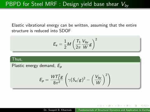
Elastic vibrational energy can be written, assuming that the entirestructure is reduced into SDOF
Ee =1
2M
(T1
2π
Vby
Wg
)2
Thus,
Plastic energy demand, Ep
Ep =WT 2
1 g
8π2
(γ(Sa/g)2 −
(Vby
W
)2)
Dr. Swapnil B. Kharmale Fundamentals of Structural Dynamics and Application to Earthquake Engineering
PBPD for Steel MRF: Design yield base shear Vby
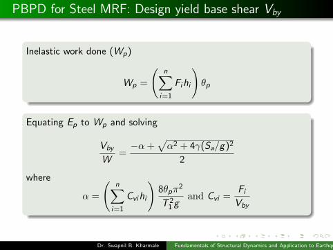
Inelastic work done (Wp)
Wp =
(n∑
i=1
Fihi
)θp
Equating Ep to Wp and solving
Vby
W=
−α +√α2 + 4γ(Sa/g)2
2
where
α =
(n∑
i=1
Cvihi
)8θpπ
2
T 21 g
and Cvi =FiVby
Dr. Swapnil B. Kharmale Fundamentals of Structural Dynamics and Application to Earthquake Engineering
PBPD for Steel MRF: Design of Floor Beams
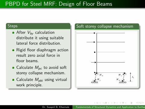
Steps
After Vby calculationdistribute it using suitablelateral force distribution.
Rigid floor diaphragm actionresult zero axial force infloor beams.
Calculate Mpc to avoid softstorey collapse mechanism.
Calculate Mpbi using virtualwork principle.
Soft storey collapse mechanism
Dr. Swapnil B. Kharmale Fundamentals of Structural Dynamics and Application to Earthquake Engineering
PBPD for Steel MRF : Design of Floor Beams
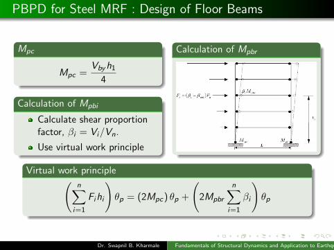
Mpc
Mpc =Vbyh1
4
Calculation of Mpbi
Calculate shear proportionfactor, βi = Vi/Vn.
Use virtual work principle
Calculation of Mpbr
Virtual work principle(n∑
i=1
Fihi
)θp = (2Mpc) θp +
(2Mpbr
n∑i=1
βi
)θp
Dr. Swapnil B. Kharmale Fundamentals of Structural Dynamics and Application to Earthquake Engineering
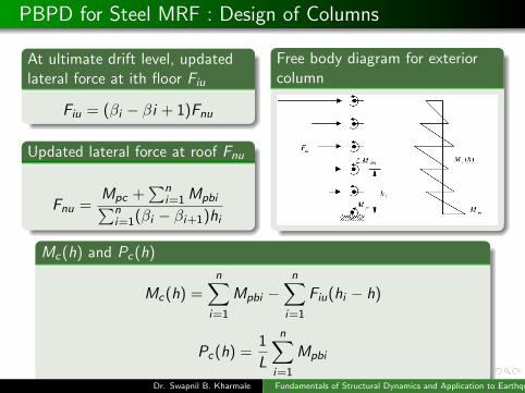
PBPD for Steel MRF : Design of Columns
At ultimate drift level, updatedlateral force at ith floor Fiu
Fiu = (βi − βi + 1)Fnu
Updated lateral force at roof Fnu
Fnu =Mpc +
∑ni=1Mpbi∑n
i=1(βi − βi+1)hi
Free body diagram for exteriorcolumn
Mc(h) and Pc(h)
Mc(h) =n∑
i=1
Mpbi −n∑
i=1
Fiu(hi − h)
Pc(h) =1
L
n∑i=1
Mpbi
Dr. Swapnil B. Kharmale Fundamentals of Structural Dynamics and Application to Earthquake Engineering
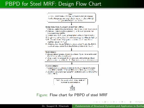
PBPD for Steel MRF: Design Flow Chart
Figure: Flow chart for PBPD of steel MRF
Dr. Swapnil B. Kharmale Fundamentals of Structural Dynamics and Application to Earthquake Engineering

THANK YOU!
Dr. Swapnil B. Kharmale Fundamentals of Structural Dynamics and Application to Earthquake Engineering