Embed Size (px)
Citation preview
This information has not been reviewed by WaterRF to determine whether it contains patentable subject matter or third-party copyrighted materials, nor has the accuracy of its information or conclusions been evaluated. Accordingly, the information is not considered published and is not available for general distribution. Until the information had been reviewed and evaluated by WaterRF, it should not be disclosed to others to reproduce, wholly or partially, without the written consent of WaterRF. ©2010 Water Research Foundation. ALL RIGHTS RESERVED. No part of this content may be copied, reproduced or otherwise utilized without permission
Performance and Life-Span of Polyethylene Wrap Materials for Ductile Iron Pipes
Literature Review Donavan Marney, Dhammika De Silva Water for a Healthy Country Flagship Report June 2010
This information has not been reviewed by WaterRF to determine whether it contains patentable subject matter or third-party copyrighted materials, nor has the accuracy of its information or conclusions been evaluated. Accordingly, the information is not considered published and is not available for general distribution. Until the information had been reviewed and evaluated by WaterRF, it should not be disclosed to others to reproduce, wholly or partially, without the written consent of WaterRF. ©2010 Water Research Foundation. ALL RIGHTS RESERVED. No part of this content may be copied, reproduced or otherwise utilized without permission - 1 -
CONTENTS Acknowledgments........................................................................................................................ 3
Executive Summary .................................................................................................................... 4
1. Introduction ....................................................................................................................... 5
2. PE wrap as a means for corrosion protection of DI pipe .............................................. 6
3. Standards for PE sleeving ................................................................................................ 8 3.1. US Standard for PE sleeving – ANSI/AWWA C105/A21.5 .................................... 8 3.2. Australian standard for PE sleeving – AS 36810 and AS 3681 ................................ 9 3.3. British and European standards ................................................................................ 9 3.4. Comparison of US and Australian standards for PE sleeving .................................. 9
3.4.1. Installation Method ................................................................................... 9 3.4.2. Sleeve attachment/securing ....................................................................... 9 3.4.3. Material requirements ............................................................................. 10
4. Durability of PE film in soil environments ................................................................... 11
5. Efficacy of PE sleeving .................................................................................................... 13 5.1. Canadian/US experience/studies............................................................................. 13 5.2. Australian experience/studies ................................................................................. 15 5.3. European and other studies ..................................................................................... 20 5.4. Australian Industry Survey ..................................................................................... 20
6. Costs associated with PE encasement of DI Pipe ......................................................... 22
7. Recycled iron in DI pipe manufacture .......................................................................... 24
8. Conclusion ....................................................................................................................... 24
9. Appendix 1 ....................................................................................................................... 26
10. References ........................................................................................................................ 28
This information has not been reviewed by WaterRF to determine whether it contains patentable subject matter or third-party copyrighted materials, nor has the accuracy of its information or conclusions been evaluated. Accordingly, the information is not considered published and is not available for general distribution. Until the information had been reviewed and evaluated by WaterRF, it should not be disclosed to others to reproduce, wholly or partially, without the written consent of WaterRF. ©2010 Water Research Foundation. ALL RIGHTS RESERVED. No part of this content may be copied, reproduced or otherwise utilized without permission - 2 -
LIST OF FIGURES Figure 1: Comparison in the spread in molecular weights and branch chains in LDPE and HDPE(Adapted from ‘Manufacture of Polyethylene’ by NZ Inst. of Chemistry)....................................................................................................................... 12
LIST OF TABLES Table 1: Material Requirements for PE Wrap Application ................................................... 11
Table 2: Exhumation observation of PE sleeved Cast Iron pipe in Hunter Region, NSW (adapted from (Ferguson and Nicholas, 1983)) ...................................................................................................................... 18
Table 3: Summary of South Australian field study on PE-sleeved pipe (Adapted from (Ellis, Moore et al., 1998)) ............................................................. 19
Table 4: European field trial results on DI pipes (Collins and Padley, 1983) ....................................................................................................................... 20
Table 5: Australian water authority opinion on the effectiveness of PE sleeving for corrosion protection of DI pipes ......................................................... 21
Table 6: Cost of DI pipe and different protective systems(Kroon, 2006) ............................. 26
Table 7: Cost of CP protection of pipe as supplied with asphaltic base coat (Kroon, 2006) .................................................................................................. 27
This information has not been reviewed by WaterRF to determine whether it contains patentable subject matter or third-party copyrighted materials, nor has the accuracy of its information or conclusions been evaluated. Accordingly, the information is not considered published and is not available for general distribution. Until the information had been reviewed and evaluated by WaterRF, it should not be disclosed to others to reproduce, wholly or partially, without the written consent of WaterRF. ©2010 Water Research Foundation. ALL RIGHTS RESERVED. No part of this content may be copied, reproduced or otherwise utilized without permission - 3 -
ACKNOWLEDGMENTS Organizations
This Project is a collaborative one between the Commonwealth Scientific Industrial Research Organization (CSIRO) – Water for a Healthy Country Flagship and the Water Research Foundation (WaterRF).
It is supported by in-kind contributions from the following water utilities:
§ City of Akron Public Utilities (Ohio - USA)
§ Greater Cincinnati Water Works (Ohio - USA)
§ Las Vegas Valley Water District (Nevada - USA)
§ Metropolitan Utilities District (Omaha - USA)
§ Pinellas County Utilities (Florida - USA)
§ South East Water (Victoria – Aus)
§ Sydney Water (New South Wales – Aus)
Project Dates
§ Project Start Date: 1st April 2010
§ Project End Date: 31st October 2013
Project Funding:
§ Total: US$462,996:
§ WaterRF: US$200,000,
§ CSIRO: US$200,000;
§ In-Kind from Utilities: US$63,000
This information has not been reviewed by WaterRF to determine whether it contains patentable subject matter or third-party copyrighted materials, nor has the accuracy of its information or conclusions been evaluated. Accordingly, the information is not considered published and is not available for general distribution. Until the information had been reviewed and evaluated by WaterRF, it should not be disclosed to others to reproduce, wholly or partially, without the written consent of WaterRF. ©2010 Water Research Foundation. ALL RIGHTS RESERVED. No part of this content may be copied, reproduced or otherwise utilized without permission - 4 -
EXECUTIVE SUMMARY The literature and utility experience indicates polyethylene (PE) wrap is an effective protection method for ductile iron pipe (DIP) in corrosive environments when installed without breaches to the PE film. However, in practice this does not occur, even though the installation specifications and procedures are detailed in numerous standards and industry guidelines. The lapses in protection performance is due principally to ingress of moisture from undetected damage to the wrap and from sealing breaches at joints and appurtenances such as service tappings, branch off-takes and valve insertions.
Although, the industry documents acknowledge that moisture ingress is unavoidable, especially during installation, it is suggested that oxygen in the trapped water will ultimately be consumed by corrosion, arresting further or continued corrosive action. This is disputed by industry practitioners and continues to be a controversial issue.
Deterioration of the PE wrap material in the soil burial environment from chemical or microbial action has not been recorded at test burial sites or at failure excavations. The samples at test sites are approaching 60 years while failure sites are aged around 40 years at best. Any breaches at failure sites have been attributed to damage at installation from poor workmanship or subsequent attachment of appurtenances. However the wrap is continuously stressed in service due to the weight of the pipe and from shrink/swell movement of soil. Although PE is able to stress relieve over time, the long term effects of burial stresses needs to be investigated. The long term effect of microbiological action also warrants investigation. While literature points to PE as bio-inert, some studies point to possible changes to the PE molecular structure by some fungi under specific conditions.
Another aspect that warrants investigation is the adhesive properties of sealing tapes used for PE wrap installation. Due to the inert properties of PE, the adhesion between the tape and PE film is purely electrostatic, and not chemical. Failure or diminution of the adhesive strength with age, especially under moist or water logged conditions is possible. While the literature does not record the condition of the sealing tape at excavations, long term adhesive properties of sealing tapes in soil environments should be studied.
An issue that encompasses all the factors discussed is microbial influenced corrosion (MIC). While MIC in cast iron is well documented, PE wrap protected DIP is considered safe from MIC because of the isolating barrier. However the ingress of moisture and subsequent depletion of oxygen in the confined space creates an environment that is suited for MIC processes such as that from aerobic or anaerobic sulfur reducing bacteria (SRB). The MIC action may not be limited to DI, as microbial action on polymers under anaerobic conditions is also a possibility.
This information has not been reviewed by WaterRF to determine whether it contains patentable subject matter or third-party copyrighted materials, nor has the accuracy of its information or conclusions been evaluated. Accordingly, the information is not considered published and is not available for general distribution. Until the information had been reviewed and evaluated by WaterRF, it should not be disclosed to others to reproduce, wholly or partially, without the written consent of WaterRF. ©2010 Water Research Foundation. ALL RIGHTS RESERVED. No part of this content may be copied, reproduced or otherwise utilized without permission - 5 -
1. INTRODUCTION Underground pipes play a vital role in the drinking water and wastewater systems across the world. However pipeline breaks are a daily occurrence, estimated at over 700 per day for water mains across North America (Lary, 2000) and over 75 per day in a large Australian cities (De Silva, 2010). A number of reviewers have suggested that managing the annual problems associated with their deterioration is likely to cost tens of billion dollars in the US (Lary, 2003) and $200M in Australia (Davis, Allan et al., 2003). Although age is considered to be the primary contributor to pipe deterioration and consequent breaks; in relation to iron pipes which account for majority of pipes in water distribution systems, the problems stem from pipe corrosion (Lary, 2000). Many factors contribute to external corrosion induced failures including pipe-soil electrochemical interaction, microbiological action, stray currents, coupling with dissimilar metals and soil stresses from seasonal soil moisture content changes. As the predominant deterioration mechanism from these is electrochemical corrosion, the physical environment in which the pipe is placed has a significant impact on the deterioration rate. This in turn has generated many preventative methods for protecting buried iron pipes from the chemical influence of the surrounding soil.
Ductile iron pipes (DIP) was introduced in the 1960s as an improved alternative to grey cast iron pipe (CIP), and they dominated new water distribution installations from the 1970’s and 1980’s. Whilst DI had similar corrosion properties to that of CI (Gummow, 1984), as a result of its enhanced strength compared to grey CI and DIP’s manufactured for equivalent pressure ratings had thinner walls (Rajani and Kleiner, 2003). This in combination with a factory provided asphaltic external coating, and copper water services in close proximity, led to the development of corrosion cells which in turn resulted in accelerated perforation of the DI at coating defects. Other forms of failure, i.e., through pipe-soil electrochemical action, also occurred in corrosive soils. In North America, there has been an increased incidence of failures observed in the 1970s (Jakobs and Hewes, 1987; Brander, 2001), which has generally been considered to be premature, since the piping was less than 10 years old (Gummow, 2000). The response from the pipeline manufacturing industry was recommendations for additional corrosion protection measures in potentially high risk soil environments. Based on research and the DIP industry recommendations, the most widely practiced method of external protection was field applied encasement of the pipe in polyethylene (PE) film, also known as PE wrap or PE sleeving (Crabtree, Breslin et al., 2007). This was supplemented with cathodic protection (CP) (Lary, 2003), for enhanced protection in soil environments considered strongly aggressive (Lindemuth and Kroon, 2009). Another method of protection generally available for buried iron pipelines is the factory application of a bonded dielectric coating such as polyethylene. Although it is more common for steel pipelines in below ground installations for oil and gas transmission/distribution systems, they have not been considered cost effective for water distribution networks and hence were unavailable for DI pipe.
As with any protective system, the efficacy of PE wrap relies upon appropriate and proper installation, with due attention given to the soil corrosivity as articulated by the Ductile Iron Pipe Research Association (DIPRA) (Bonds, 1995; Bonds, Barnard et al., 2005; Crabtree, Breslin et al., 2007; DIPRA, 2007; Crabtree and Breslin, 2008). Bonds noted the need to consider other non-PE wrap options for uniquely severe environments such as swamps and tidal muck areas (Bonds, 1995). There are however, contradictory findings in the literature which suggest that PE wrap does not adequately protect against corrosion. A number of researchers including Szeliga and Simpson (Szeliga and Simpson, 2001), and Szeliga (Szeliga, 2005; Szeliga, 2007; Szeliga, 2007; Szeliga, 2008) have observed, that regardless of whether the PE wrap was damaged or intact, quite severe corrosion of the DIP was possible.
Szeliga showed that regardless of PE- wrap protection or not, DIP external corrosion was minimal in benign soils (Szeliga, 2005). The service history, however, in corrosive soils has been mixed. While the
This information has not been reviewed by WaterRF to determine whether it contains patentable subject matter or third-party copyrighted materials, nor has the accuracy of its information or conclusions been evaluated. Accordingly, the information is not considered published and is not available for general distribution. Until the information had been reviewed and evaluated by WaterRF, it should not be disclosed to others to reproduce, wholly or partially, without the written consent of WaterRF. ©2010 Water Research Foundation. ALL RIGHTS RESERVED. No part of this content may be copied, reproduced or otherwise utilized without permission - 6 -
industry and independent reports have produced evidence of good performance in controlled and field environments, when the PE wrap protection was applied according to the specified standards (Ferguson and Nicholas, 1983; Ellis, Moore et al., 1998; Crabtree, Breslin et al., 2007; Horton, 2008), others have expressed views to the contrary (Szeliga, 2007; Szeliga, 2008). The differing viewpoints and reports of failures both with and without PE wrap for pipes with less than 35 years service, (Szeliga, 2007; Szeliga, 2007), prompted a US government instrumentality to specify the types of external corrosion protection required when DIP’s are installed in soils with different degrees of corrosivity (BoR, 2009). In essence the corrosion mitigation method for DIP was specified on the basis of soil resistivity (ohm-cm). The document specified protection of DIP with PE wrap in soils of low corrosivity (≥ 3000 ohm-cm), PE wrap and CP in moderately corrosive soils (2000-3000 ohm-cm) and bonded dielectric coatings and CP for highly corrosive soils (≤ 2000 ohm-cm). As a result of industry disagreement on these specifications within the industry, a wide-ranging review of the specifications found that based on current knowledge a 50 year service life could not be assured in highly corrosive soils for DI pipe protected by PE wrap and CP (BoR, 2009).
This literature review will be the basis of a research project to independently evaluate and predict the long-term performance and life expectancy of PE wrap material used to protect DIP from external corrosion. The project will evaluate and/or develop testing, evaluation and accelerated material life testing methods for PE wrap materials, whilst bearing in mind the underlying issues involved with simulation of actual burial conditions. This project will complement the ongoing AwwaRF project 3036, Long Term Performance of Ductile-Iron Pipe, and address the industry needs relative to issues relating to PE wrap raised in the substantial review conducted by Rajani and Kleiner on the three main methods for corrosion protection of DIP’s when installed in corrosive soils (Rajani and Kleiner, 2003). The combined life-expectancy results will form the basis for asset management decisions and future rehabilitation program spending levels.
2. PE WRAP AS A MEANS FOR CORROSION PROTECTION OF DI PIPE A United Kingdom water industry research (UK WIR), suggested that PE wrap functions by (WRc, 1984):
§ Preventing contact between the pipeline and the surrounding backfill; direct contact between unprotected DI mains and corrosive soils can lead to extremely intense and highly localised corrosion pitting events;
§ Promoting the formation of a relatively uniform aqueous environment between the pipe surface and the sleeving film thus ensuring that any corrosion which might occur will tend to be uniformly distributed over the pipe surface, rather than being concentrated in localised areas. This restricts the depth of the corrosion pitting on sleeved ductile iron mains, with the effect maximised if the sleeving is installed to fit snugly around the pipe. This is always the case for factory applied sleeving available in the UK where the application is via purpose built machines on the factory finishing lines; these processes restrict:
§ The access of oxygen, which essential for the aqueous corrosion of iron in non-acidic aerobic electrolytes and
§ The access of nutrients, which are necessary to sustain the activity of sulphate-reducing bacteria which can stimulate corrosion of iron in anaerobic environments, which in turn minimises the rate of attack on sleeved ductile iron mains.
This information has not been reviewed by WaterRF to determine whether it contains patentable subject matter or third-party copyrighted materials, nor has the accuracy of its information or conclusions been evaluated. Accordingly, the information is not considered published and is not available for general distribution. Until the information had been reviewed and evaluated by WaterRF, it should not be disclosed to others to reproduce, wholly or partially, without the written consent of WaterRF. ©2010 Water Research Foundation. ALL RIGHTS RESERVED. No part of this content may be copied, reproduced or otherwise utilized without permission - 7 -
PE film, developed in the 1950s, and was tested as PE wrap in the late 1950’s for protection of CIP, and subsequently introduced as a corrosion protection method for DIP’s in the late 1960’s. The protection method has since been adopted within various standards in the US, and other countries such as Japan, UK, Germany, and Australia. The standard method calls for DIP to be encased with loose sleeves of either 8 mil (200 microns) low density polyethylene (LDPE) or 4 mil (100 microns) high density polyethylene (HDPE) and cross laminated HDPE (CLHDPE). PE resins produce a very tough film with characteristics including resistance to most chemicals, good moisture resistance, excellent electrical resistance and high dielectric strength. As a result of these properties, loose PE wrap is the standard corrosion control method recommended by DIPRA for the protection of DIP’s in corrosive environments. It is a passive corrosion control method, which unlike other systems such as cathodic protection, requires no on-going maintenance or pipe monitoring after installation. As a result, the operational costs of asset protection are significantly lower than for example CP over the asset lifespan. In addition, DIPRA has reported a number of advantages of this means of corrosion control, including:
§ Ease of installation,
§ Low cost,
§ No deterioration once below ground, and
§ Easy repair if damaged during installation.
PE films are produced by blown film-extrusion technology, and both LDPE and HDPE tubes have higher physical strength characteristics in the machine direction than in the transverse direction. HDPE in addition has higher permeation resistance than LDPE because of its molecular structure. Cross laminated HDPE, is produced by laminating longitudinally and transversely oriented films, has an enhanced tear and puncture resistance while retaining the permeation resistance of HDPE.
PE is not resistant to ultra violet (UV) light and therefore is degraded by exposure to sunlight. However, although this is not an issue once buried in its application, the film is protected from UV exposure during transport and storage and by introducing carbon black or UV stabilisers to counter sunlight or UV weathering.
Unlike bonded coatings, PE sleeving does not electrically isolate the pipe. It is intended to isolate the pipe from the soil environment, although it does not completely seal the pipe. During installation, PE sleeving is loosely wrapped around the pipe length and secured in place using straps or adhesive tape. The pipe trench is then backfilled, firmly pressing the sleeve against the pipe outer surface and reducing the likelihood of groundwater infiltration. Although it is possible for water entrapment between the pipe and sleeve during installation (with consequent initial rusting), it has been suggested that this is not a major issue as oxygen in the trapped water will ultimately be consumed by cathodic reactions thereby polarizing the pipe surface and preventing further corrosion (Malizio, 1986). This polarization slows the rate of cathodic reactions associated with corrosion until equilibrium is attained. For buried pipes, polarization typically occurs near the cathode, where upon receiving electrons, hydrogen ions are converted to hydrogen gas. Rajani and Kleiner reported that the increased presence of hydrogen gas retards the delivery of electrons from the cathode to the hydrogen ions, until the potential difference between the cathode and anode is sufficiently low to prevent the flow of corrosion current (Rajani and Kleiner, 2003). However, this proposition has encountered some scepticism with the belief by many corrosion engineers, that trapped moisture, will, in the long term, create local corrosion cells. Specifically, analyses of field study data of DIP’s protected with PE sleeving indicated that entrapped moisture caused corrosion failure eight years after installation (Szeliga, 1991). It is interesting to note that the oxygen depletion theory may
This information has not been reviewed by WaterRF to determine whether it contains patentable subject matter or third-party copyrighted materials, nor has the accuracy of its information or conclusions been evaluated. Accordingly, the information is not considered published and is not available for general distribution. Until the information had been reviewed and evaluated by WaterRF, it should not be disclosed to others to reproduce, wholly or partially, without the written consent of WaterRF. ©2010 Water Research Foundation. ALL RIGHTS RESERVED. No part of this content may be copied, reproduced or otherwise utilized without permission - 8 -
not be true for all conditions where PE sleeving is used e.g., in tidal and variable groundwater conditions, where the moist air gap between the PE sleeve and the pipe is periodically replenished which would sustain corrosion; and where the cathode in the corrosion cell is external to the water main (i.e., copper service pipes). In the latter case, no oxygen depletion is likely to occur at the pipe, which is anodic in this reaction.
The PE sleeving method is considered to be relatively inexpensive and since it is applied in the trench, there is a reduced risk of damage during pipe transport, storage and handling. However, the PE sleeve can be torn as a result of interaction with stones in the trench, which in turn, may lead to localised corrosion. Consequently, PE sleeved pipe must be installed carefully to avoid cuts (Ash, 1998), and to ensure that the pipe is free of lumps of clay prior to backfilling (Collins and Padley, 1983). The type of PE material used for sleeving has changed since its introduction in the late 1960’s with the initial use of 8 mil (400 microns) thick LDPE sleeve, followed by high density HDPE and CLHDPE films. More recently, linear low density PE (LLDPE) has become more widespread. While maintaining the excellent properties of HDPE, CLHDPE was generally thought to provide the film with an improved resistance to tearing and puncture compared to LDPE and HDPE; however, there are some contradictory findings regarding the comparative strengths of LLDPE and CLHDPE. In a field evaluation of DIP for trenchless applications, the results suggested that 8 mil LLDPE is more durable than the standard 4 mil CLHDPE (Carpenter and Conner, 2003), while the 2007 update of the DIPRA technical document (DIPRA, 2007) suggests that 8 mil LLDPE and 4 mil CLHDPE provide comparable protection in aggressive environments. However, whichever sleeve material is used it needs to meet the performance requirements stipulated in the relevant standard.
3. STANDARDS FOR PE SLEEVING The most widely applied standards specifying the installation and material requirements of loose PE sleeving are the American (ANSI/AWWA, 1999), Australian (AS3681, 1989), British (BS6076, 1996) and European (ISO8180, 2006) standards.
3.1. US Standard for PE sleeving – ANSI/AWWA C105/A21.5 Three installation methods are outlined in ANSI/AWWA C105/A21.5 (ANSI/AWWA, 1999); Methods A and B for PE sleeve and Method C for PE sheet. The main differences between Methods A and B is that in Method A, the PE sleeve is overlapped at the joints, while in Method B, a length of PE tube is used for the barrel of the pipe and separate pieces of tube or sheets are used for the joint areas. Method A is the preferred method since it does not require extra sleeve or sheet to be used at the joints, allowing for a simpler and easier process. Method A is often used for dry trench conditions since the sleeve is pulled along the pipe length after the pipe has been lowered into the trench. The standard does not allow its use in wet trench conditions, since clay or soil may be trapped between the sleeve and the pipe during installation.
It should be noted that in wet trench conditions, the pipe must be completely encased by the PE sleeve before it is lowered into the trench in order to prevent ground water or soil infiltrating the area between the pipe and the PE film. For this reason, a modified version of Method A is used for wet trench conditions. Method B is similar to the installation method used in the Australian standard AS 3681 - 1989.
Method B is not recommended for bolt type joints unless an additional layer of PE sleeve is used over the joint area in order to prevent any sharp edges perforating the encasement. A shallow bell hole is also needed in the bottom of the trench to enable the 900 mm sleeve length to be pulled over the joint.
This information has not been reviewed by WaterRF to determine whether it contains patentable subject matter or third-party copyrighted materials, nor has the accuracy of its information or conclusions been evaluated. Accordingly, the information is not considered published and is not available for general distribution. Until the information had been reviewed and evaluated by WaterRF, it should not be disclosed to others to reproduce, wholly or partially, without the written consent of WaterRF. ©2010 Water Research Foundation. ALL RIGHTS RESERVED. No part of this content may be copied, reproduced or otherwise utilized without permission - 9 -
In both methods A and B, it is strongly recommend that a soft fabric type sling or suitably padded cable be used to reduce the risk of external damage to the PE sleeve during the lifting operations. The use of a padded sling would be of more importance in method B, since the sleeve is pulled along the length of the pipe prior to being lifted into the trench resulting in the sling being placed around the encasement during this operation. As a result of the sling being wrapped around the PE encased pipe, damage could easily occur.
3.2. Australian standard for PE sleeving – AS 36810 and AS 3681 There are two Australian standards for PE encasement: AS 3680 (AS3680, 1989) and AS 3681 (AS3681, 1989). The former stipulates the criteria for the PE material intended for encasement of DIP systems. Guidelines are set out to evaluate the ultimate tensile strength, elongation, impact resistance, and tear and UV resistance. AS 3681 provides guidelines for the application of PE sleeving to DI pipelines and fittings, and is comparable to the US standard ANSI/AWWA C105/A21.5. A key recommendation contained within in AS 3681 is that the pipe and fittings be sleeved individually prior to laying, as apposed to pre–sleeving of a number of pipes prior to laying; in addition the standard specifies the need for the pipe and fitting surface to be free of clay/soil or any other foreign material prior to fixing the sleeve to the pipe, as these may result in damage to the film.
3.3. British and European standards BS 6076:1996 (BS6076, 1996) and ISO 8180:2006 (ISO8180, 2006) are essentially similar, and as with the Australian standard are adaptations of the US standard. The British standard allows for factory applied sleeves in addition to site application. Factory application of PE sleeving ensures that the sleeving material is wrapped tightly and uniformly over the pipe barrel. In addition, application in the factory eliminates the risk of soil entrapment between the sleeving and the pipe surface, which can be a problem with the site application method. However care must be taken in the transportation, handling and laying of factory-sleeved pipe to minimise the risk and extent of damage to sleeves,
3.4. Comparison of US and Australian standards for PE sleeving 3.4.1. Installation Method In the US standard ANSI/AWWA C105/A21.5, two main installation methods, methods A and B for dry and wet trench conditions are recommended respectively. The installation method outlined in AS 3681 appears to be heavily based on that of Method B in ANSI/AWWA C105/A21.5. Method B is the preferred method of installation since the likelihood of soil or clay being trapped between the sleeve and the pipe is greatly reduced.
3.4.2. Sleeve attachment/securing One of main differences between the two standards is the criterion for securing of the sleeving. A maximum distance of 600 mm is proposed in ANSI/AWWA C105/A21.5 compared to 1000 mm in the AS 3681. In wet soil conditions, or areas that are subject to tidal movement (i.e., installation below the water table) this increased spacing requirement could increase the likelihood of groundwater breaching the sleeving. Alternatively, by reducing the free space between the pipe and the sleeve, the likelihood of tearing (since the PE sleeve can accommodate less movement relative to the pipe) is increased.
ANSI/AWWA C105/A21.5 standard discusses the potential problems that may occur when the sleeve is pulled too tightly around the pipe circumference during installation. AS 3681 states that the sleeve should
This information has not been reviewed by WaterRF to determine whether it contains patentable subject matter or third-party copyrighted materials, nor has the accuracy of its information or conclusions been evaluated. Accordingly, the information is not considered published and is not available for general distribution. Until the information had been reviewed and evaluated by WaterRF, it should not be disclosed to others to reproduce, wholly or partially, without the written consent of WaterRF. ©2010 Water Research Foundation. ALL RIGHTS RESERVED. No part of this content may be copied, reproduced or otherwise utilized without permission - 10 -
have a tight fit around the barrel of the pipe, however it is the area of the joint that is known to be of greater concern. If the sleeve is pulled too tightly around the pipe barrel, due to the increase in outside diameter of the pipe in the joint area, there is the possibility of stretching of the sleeve where different contours and shapes are encountered. If excessive stretching is present, tearing of the sleeve can result from the load of the backfill.
ANSI/AWWA C105/A21.5 also considers the installation of service connections, which can cause damage to the sleeve if not undertaken correctly. AS 3681 does not provide any guidance on the installation of service connections.
AS 3681 provides a good reference and guideline for installing PE encasement and when compared to ANSI/AWWA C105/A21.5, many similarities can be drawn. However some distinct differences, such as the securing intervals of the sleeve and the lack of guidance/procedures for the installation of service connections are noted. One of the most distinct advantages that ANSI/AWWA C105/A21.5 has compared to AS 3681 is the inclusion of the 10-point soil evaluation survey, which is used to determine the suitability of PE encasement in every particular field environment prior to selecting any corrosion prevention system.
From the literature and papers sighted and referenced during this review, the main standard referenced is ANSI / AWWA C105 / A21.5 primarily because the majority of the research undertaken on DIP encasement has taken place in the United States. Although alternate installation methods have also been developed, the methods discussed in this section of the literature review are found to be the most widely used and the most effective (Miller, 1985).
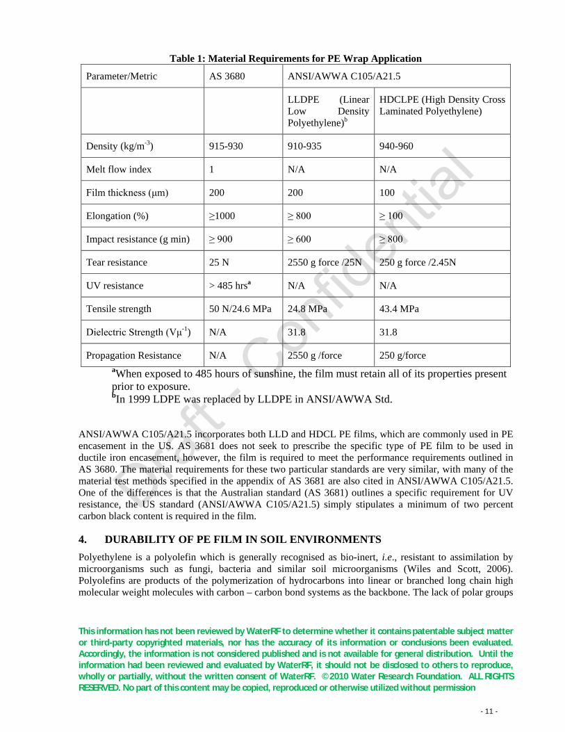
3.4.3. Material requirements The general material requirements outlined in both AS 3680 and ANSI/AWWA C105/A21.5 are outlined below in Table 1. In ANSI/AWWA C105/A21.5, both the material and installation requirements have been incorporated into one standard. A separate Australian Standard AS 3681 has been written to outline the guidelines for sleeving application.
This information has not been reviewed by WaterRF to determine whether it contains patentable subject matter or third-party copyrighted materials, nor has the accuracy of its information or conclusions been evaluated. Accordingly, the information is not considered published and is not available for general distribution. Until the information had been reviewed and evaluated by WaterRF, it should not be disclosed to others to reproduce, wholly or partially, without the written consent of WaterRF. ©2010 Water Research Foundation. ALL RIGHTS RESERVED. No part of this content may be copied, reproduced or otherwise utilized without permission - 11 -
Table 1: Material Requirements for PE Wrap Application
Parameter/Metric AS 3680 ANSI/AWWA C105/A21.5
LLDPE (Linear Low Density Polyethylene)b
HDCLPE (High Density Cross Laminated Polyethylene)
Density (kg/m-3) 915-930 910-935 940-960
Melt flow index 1 N/A N/A
Film thickness (μm) 200 200 100
Elongation (%) ≥1000 ≥ 800 ≥ 100
Impact resistance (g min) ≥ 900 ≥ 600 ≥ 800
Tear resistance 25 N 2550 g force /25N 250 g force /2.45N
UV resistance > 485 hrsa N/A N/A
Tensile strength 50 N/24.6 MPa 24.8 MPa 43.4 MPa
Dielectric Strength (Vμ-1) N/A 31.8 31.8
Propagation Resistance N/A 2550 g /force 250 g/force aWhen exposed to 485 hours of sunshine, the film must retain all of its properties present prior to exposure. bIn 1999 LDPE was replaced by LLDPE in ANSI/AWWA Std.
ANSI/AWWA C105/A21.5 incorporates both LLD and HDCL PE films, which are commonly used in PE encasement in the US. AS 3681 does not seek to prescribe the specific type of PE film to be used in ductile iron encasement, however, the film is required to meet the performance requirements outlined in AS 3680. The material requirements for these two particular standards are very similar, with many of the material test methods specified in the appendix of AS 3681 are also cited in ANSI/AWWA C105/A21.5. One of the differences is that the Australian standard (AS 3681) outlines a specific requirement for UV resistance, the US standard (ANSI/AWWA C105/A21.5) simply stipulates a minimum of two percent carbon black content is required in the film.
4. DURABILITY OF PE FILM IN SOIL ENVIRONMENTS Polyethylene is a polyolefin which is generally recognised as bio-inert, i.e., resistant to assimilation by microorganisms such as fungi, bacteria and similar soil microorganisms (Wiles and Scott, 2006). Polyolefins are products of the polymerization of hydrocarbons into linear or branched long chain high molecular weight molecules with carbon – carbon bond systems as the backbone. The lack of polar groups
This information has not been reviewed by WaterRF to determine whether it contains patentable subject matter or third-party copyrighted materials, nor has the accuracy of its information or conclusions been evaluated. Accordingly, the information is not considered published and is not available for general distribution. Until the information had been reviewed and evaluated by WaterRF, it should not be disclosed to others to reproduce, wholly or partially, without the written consent of WaterRF. ©2010 Water Research Foundation. ALL RIGHTS RESERVED. No part of this content may be copied, reproduced or otherwise utilized without permission - 12 -
such as carbon – oxygen bond systems within the chains to provide the necessary polarity for microbial interaction, imparts hydrophobic properties to polyolefins that inhibits growth of microorganisms (Colin, Cooney et al., 1976). It has been observed however that the oxidation products of polyolefins are biodegradable (Albertsson and Karlsson, 1988). Such products have reduced molecular mass and incorporate oxygen containing polar groups at chain scission sites. There is evidence of support for microbial growth after weathering, by exposure of the polymer film to UV light, which is a common mechanism of oxidation (Mills and Eggins, 1970; Eggins, Mills et al., 1971).
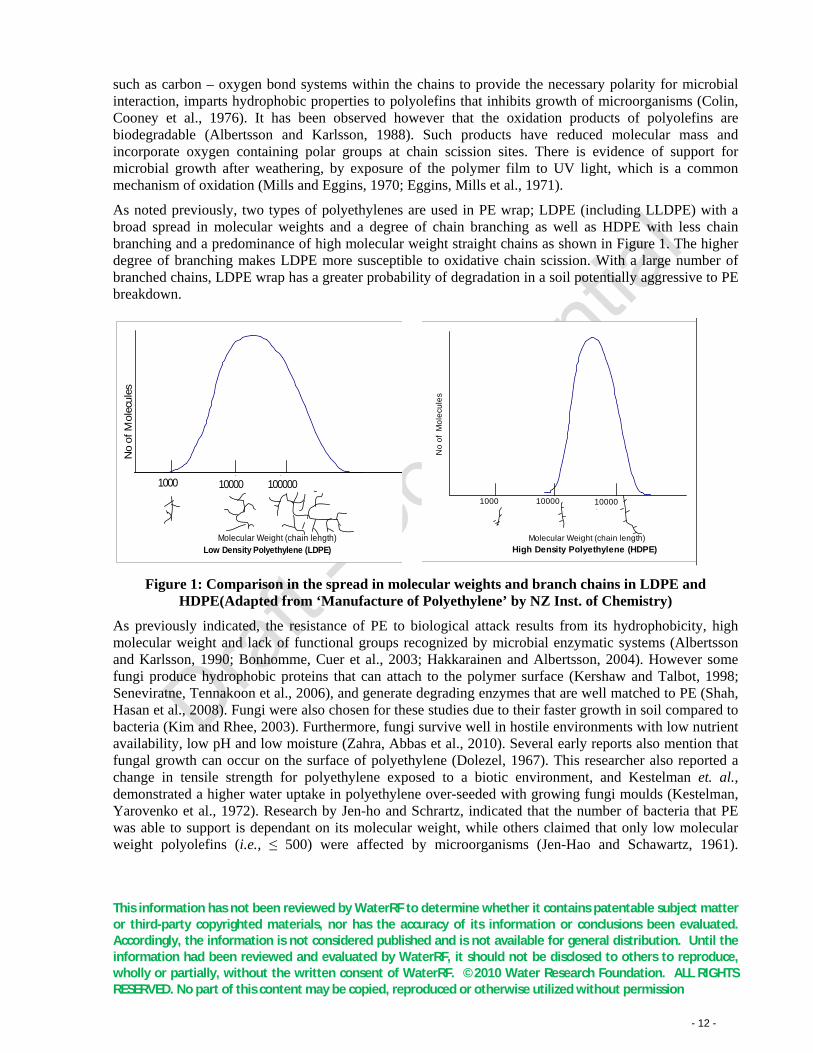
As noted previously, two types of polyethylenes are used in PE wrap; LDPE (including LLDPE) with a broad spread in molecular weights and a degree of chain branching as well as HDPE with less chain branching and a predominance of high molecular weight straight chains as shown in Figure 1. The higher degree of branching makes LDPE more susceptible to oxidative chain scission. With a large number of branched chains, LDPE wrap has a greater probability of degradation in a soil potentially aggressive to PE breakdown.
Molecular Weight (chain length)Low Density Polyethylene (LDPE)
No
of
Mo
lecu
les
10000 1000001000
Molecular Weight (chain length)High Density Polyethylene (HDPE)
1000 10000 100000
No
of M
olec
ules
Figure 1: Comparison in the spread in molecular weights and branch chains in LDPE and
HDPE(Adapted from ‘Manufacture of Polyethylene’ by NZ Inst. of Chemistry)
As previously indicated, the resistance of PE to biological attack results from its hydrophobicity, high molecular weight and lack of functional groups recognized by microbial enzymatic systems (Albertsson and Karlsson, 1990; Bonhomme, Cuer et al., 2003; Hakkarainen and Albertsson, 2004). However some fungi produce hydrophobic proteins that can attach to the polymer surface (Kershaw and Talbot, 1998; Seneviratne, Tennakoon et al., 2006), and generate degrading enzymes that are well matched to PE (Shah, Hasan et al., 2008). Fungi were also chosen for these studies due to their faster growth in soil compared to bacteria (Kim and Rhee, 2003). Furthermore, fungi survive well in hostile environments with low nutrient availability, low pH and low moisture (Zahra, Abbas et al., 2010). Several early reports also mention that fungal growth can occur on the surface of polyethylene (Dolezel, 1967). This researcher also reported a change in tensile strength for polyethylene exposed to a biotic environment, and Kestelman et. al., demonstrated a higher water uptake in polyethylene over-seeded with growing fungi moulds (Kestelman, Yarovenko et al., 1972). Research by Jen-ho and Schrartz, indicated that the number of bacteria that PE was able to support is dependant on its molecular weight, while others claimed that only low molecular weight polyolefins (i.e., ≤ 500) were affected by microorganisms (Jen-Hao and Schawartz, 1961).
This information has not been reviewed by WaterRF to determine whether it contains patentable subject matter or third-party copyrighted materials, nor has the accuracy of its information or conclusions been evaluated. Accordingly, the information is not considered published and is not available for general distribution. Until the information had been reviewed and evaluated by WaterRF, it should not be disclosed to others to reproduce, wholly or partially, without the written consent of WaterRF. ©2010 Water Research Foundation. ALL RIGHTS RESERVED. No part of this content may be copied, reproduced or otherwise utilized without permission - 13 -
Albertsson and Banhidi argued that from a chemical point of view, it can be anticipated that microorganisms may be able to degrade PE since the chemical structure of PE is similar to that of linear alkanes, which are known to be biodegradable (Albertsson and Banhidi, 1980).
Almost every survey and investigation of the biological degradation of PE suggests that it is an inert polymer with good resistance to microorganisms, however, the research has largely been driven by the environmental concerns around the resistance of PE to degradation after disposal and consequent pollution and damage to ecosystem (2005). Very little effort has been directed towards predicting the long-term performance of PE in soil from the viewpoint of obtaining lifetimes of 50 to 100 years. However as the literature reviewed here indicates there is some evidence of its susceptibility to deterioration under specific conditions, it is not advisable to entirely discount that possibility especially as the PE wrap could be subjected to abnormal stresses from the weight of the pipeline and soil shrink-swell properties. As surmised by Albertsson and Banhidi; ‘for any reliable valid prediction of the durability of an “inert” synthetic polymer in use; it is only if all the minor events of degradation and deterioration as well as their additive synergetic interaction can be taken into account will it be possible to forecast the fate of these plastics in natural surroundings and predict the time schedule of relevant destructive processes’ (Albertsson and Banhidi, 1980).
5. EFFICACY OF PE SLEEVING
5.1. Canadian/US experience/studies DIP’s were installed in Calgary, Canada, in the early 1960’s and by the end of 1980 42% of all distribution mains were DI. However, soon after their introduction, an increase in failure rate was observed from 0.5 failures per 100 km in 1970 to 29 failures per 100 km in 1980 (Jakobs and Hewes, 1987), i.e., a 58 times increase in one decade. In a follow up study commissioned by Canadian authorities (CANMET) through Caproco Corrosion Prevention Ltd., it was reported that while most of the failures resulted from corrosion leading to complete perforation of the pipe walls, and their locations appeared random, a higher frequency of corrosion pits occurred near copper service lines that were, connected (without insulation) to DIP’s via bronze saddles. Deep corrosion pits were also found in low-resistivity soils, which suggested that galvanic corrosion was a problem (Caproco, Corrosion et al., 1985). The CANMET study also found that in some cases loose PE sleeving was used for corrosion protection but there was no evidence that pipe protected with loose PE sleeving corroded at a lower rate than unprotected pipes.
In response to the CANMET report, a review conducted by DIPRA (DIPRA, 1985) questioned the validity of the study, and attributed the high corrosion rates in Calgary to joint the bonding which used for electrical thawing of pipes in cold conditions. Since new DIP’s were anodic to older CIP’s, it was proposed that electrically bonding these pipelines in order to facilitate thawing would create bi-metallic corrosion cells. Consequently, the DIP’s would protect the CIP’s, and corrode at a higher rate. In addition, DIPRA stated that a system with electrically bonded joints had a higher tendency to pick up stray currents, which also leads to higher corrosion rates. In response to comments regarding loose PE sleeving, DIPRA stated that many published reports exist showing the successful protection of DIP with this method. They claimed that the PE sleeving in Calgary probably failed due to poor application and large cuts and tears in the sleeve.
Field experiments have also been conducted in the US, resulting in contrasting findings. For example Rajani and Kleiner (Rajani and Kleiner, 2003) cited a study based on a telephone survey of various US and Canadian water authorities on the performance of the DIP’s protected against corrosion where the
This information has not been reviewed by WaterRF to determine whether it contains patentable subject matter or third-party copyrighted materials, nor has the accuracy of its information or conclusions been evaluated. Accordingly, the information is not considered published and is not available for general distribution. Until the information had been reviewed and evaluated by WaterRF, it should not be disclosed to others to reproduce, wholly or partially, without the written consent of WaterRF. ©2010 Water Research Foundation. ALL RIGHTS RESERVED. No part of this content may be copied, reproduced or otherwise utilized without permission - 14 -
respondents reported varied experiences. Of the utilities that had adopted PE sleeving for protection, some were successful in reducing leakage rates, while others had continuing problems. To combat these, several utilities chose to use two PE layers (or ‘double bagging’) to prevent local corrosion at tears and defects in the PE sleeve. Other utilities switched from DI to PVC pipes in new constructions. Some utilities also believed that the moist air gap between the pipe and the loose PE sleeving can create a shield that diminishes the effectiveness of subsequent cathodic protection. The survey had indicated that PE sleeving can be used more effectively in large transmission mains, where there are no disturbances (such as service connections, tappings or appurtenances) that can breach the continuity of the wrap. However, they also emphasized that many of the reporting utilities did not have detailed soil information and the exposure times of DIP’s to soil environments varied significantly.
Another US study reported on the effectiveness of PE sleeving in 12 US cities, between 7 and 20 years after installation (Malizio, 1986). In all cases, no significant corrosion was detected; despite the fact that all pipes were buried in soils that exceeded the DIPRA 10-point evaluation score for corrosivity (DIPRA, 2007). DIPRA also has an on-going program of pipe excavations of PE sleeved pipe in the US, which further illustrate its corrosion protection (DIPRA, 2007). This program was initiated in 1963 and has records on the performance of CI (60 excavations) and DI (72 excavations) mains. The DI mains excavated were between diameters of 4” and 42” (i.e., 100 and 1066 mm), and were aged between 6 and 32 years. Of the DI excavations, 58 were rated as either “excellent” or “very good”, 9 were rated “good” and 5 had a rating of “excellent or good where properly wrapped”. DIPRA concludes from these excavation studies that the performance of PE sleeved DIP’s in corrosive soils is acceptable (DIPRA, 2007).
In a complementary study to evaluate the level of corrosion protection required to achieve a useful life of 75 to 100 years, the performance and cost of several protection techniques were evaluated including combinations of asphaltic shop coat, PE wrap and CP (Kroon, Lindemuth et al., 2004; Kroon, 2006; Lindemuth and Kroon, 2006). The conclusions from the study were that while PE wrap is a cost effective and technically sound method for corrosion protection of DI pipe, the level of protection (i.e., shop coat only, with PE wrap or PE wrap supplemented with CP) should be chosen on a project specific basis with consideration of likelihood and consequence of corrosion failure. The study recognised the importance of enhancing quality assurance and control of PE wrap application and the synergistic effectiveness of PE wrap with CP.
Schiff and McCollom conducted a different set of field experiments to assess the effectiveness of PE-sleeving before and after impressed current cathodic protection was implemented (Schiff and McCollom, 1993). Corrosion rates were measured using steel probes between 1982 and 1992 (the probes were not grounded to the pipe until 1989) and impressed current cathodic protection was installed in 1991. The main observations from this study are summarised below (Rajani and Kleiner, 2003):
§ Corrosion rates of DI pipes with undamaged PE sleeves were very low;
§ Corrosion rates increased after the steel measurement probes were grounded to the pipe. (This was possibly due to the steel probes becoming cathodic to DI pipes);
§ Corrosion rates in both exposed and PE-sleeved pipes diminished after the application of impressed current cathodic protection;
§ Sandy backfill lowered corrosion rates compared to more corrosive native soils;
§ Electrical current requirements for cathodic protection in PE-sleeved pipe were an order of magnitude higher than those of well-coated steel pipe, but still lower than for uncoated DI pipe.
This information has not been reviewed by WaterRF to determine whether it contains patentable subject matter or third-party copyrighted materials, nor has the accuracy of its information or conclusions been evaluated. Accordingly, the information is not considered published and is not available for general distribution. Until the information had been reviewed and evaluated by WaterRF, it should not be disclosed to others to reproduce, wholly or partially, without the written consent of WaterRF. ©2010 Water Research Foundation. ALL RIGHTS RESERVED. No part of this content may be copied, reproduced or otherwise utilized without permission - 15 -
This latter observation alleviates some concerns regarding the shielding effect of the moist air gap between the pipe and the PE sleeve.
In other US studies the history of PE-sleeved DI pipes in corrosive soil environments are described (Szeliga, 1991; Szeliga, 2005). Corrosion was detected 5-8 years after pipe installation and was attributed to moisture, which had penetrated that PE sleeve, creating an oxygen differential corrosion cell. As noted by Rajani and Kleiner, this contradicts the theory (and observations) regarding the passivation of trapped moisture as described previously (Rajani and Kleiner, 2003). In follow up assessment of 60 examples of bare and PE wrapped DIP corrosion, the author questioned the reliability of the DIRPA 10 point scoring system from small soil samples and the value of performance data based on controlled soil burial tests (Szeliga, 2007; Szeliga, 2008). It was suggested that in real life installations PE wrap is likely to be damaged regardless of quality of construction and corrosion can occur under intact PE wrap from water and/or soil that migrates between the wrap and the pipe.
The following paragraph presents in summary some of the findings from the recent Bureau or Reclamation’s Review of Corrosion Prevention Standards for ductile Iron Pipe (BoR, 2009). Extensive damage to DI pressurized sewer mains was found to occur in less than 15 years in Colorado Springs, Colorado. It was speculated that the corrosion damage was caused by Microbiologically Influenced Corrosion (MIC) from sewage trapped between the PE sleeve and the pipe wall. The risk of MIC corrosion in pressurized sewer mains may be increased by the use of PE sleeving, where the sleeving retains leakage, from joints or existing pits, and keeps it in contact with the pipe encouraging corrosion. MIC researchers at Montana State University noted that MIC corrosion could be a major concern under PE sleeving in high sulphate soils and that further testing should be undertaken to determine the amount of possible attack. Failure of DI pressure sewers had also been reported due to development of air pockets at high points and subsequent deterioration of internal liner from sulphide generation (Bell, Pilko et al., 2009).
The literature on DIP corrosion, especially from North American sources, points to divergent views on the efficacy of PE wrap in corrosive soils. This was highlighted in the independent review by Rajani and Kleiner (Rajani and Kleiner, 2003). While articles from sources linked to the DIP industry provide evidence supporting the effectiveness of PE wrap, either by itself or in concert with CP (Bonds, Barnard et al., 2005; Kroon, 2006; Crabtree, Breslin et al., 2007; DIPRA, 2007; Crabtree and Breslin, 2008; Horton, 2008), others question the value on the basis that ingress of moisture/water through breaches in the wrapping is unavoidable, leading to corrosion (Szeliga and Simpson, 2001; Spickelmire, 2003). The principal cause of breaches is said to be careless installation and these sometimes shield effectiveness of CP (if in operation) at sites remote from the breach site (Lindemuth and Kroon, 2006).
5.2. Australian experience/studies Whilst the use of DIP in Australia dates back to the late 1960’s, the majority of pipes laid were installed after 1980. Data from Australian water authorities indicates that DIP’s exhibit a relatively constant failure rate of approximately 5 failures/100 km/year for the initial 8 year period after installation. For pipe ages between 8 and 23 years, failure rate increases to approximately 15 failures/100 km/year. However, it is currently unclear whether this increase in failure rate with age is due to corrosion chemistry alone, or changes in the installation of PE sleeving over time.
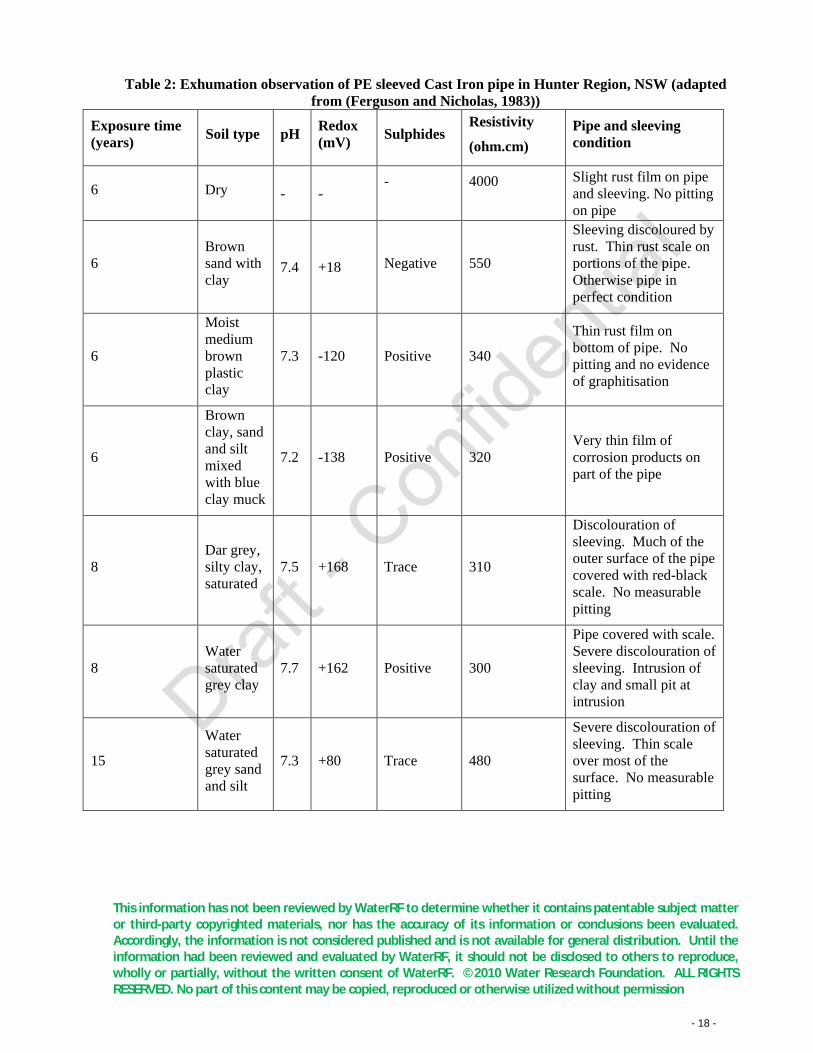
As reported by Ferguson and Nicholas, Australian field trials of PE-sleeved pipes began in 1966 in the Hunter Region of New South Wales. Several exhumations of sleeved Cast Iron pipe have been performed since 1979, and the results are summarised in These observations confirm the effective corrosion
This information has not been reviewed by WaterRF to determine whether it contains patentable subject matter or third-party copyrighted materials, nor has the accuracy of its information or conclusions been evaluated. Accordingly, the information is not considered published and is not available for general distribution. Until the information had been reviewed and evaluated by WaterRF, it should not be disclosed to others to reproduce, wholly or partially, without the written consent of WaterRF. ©2010 Water Research Foundation. ALL RIGHTS RESERVED. No part of this content may be copied, reproduced or otherwise utilized without permission - 16 -
protection of PE sleeving in corrosive soil environments. Whilst pipe failures have been reported in the Hunter Region, exhumation revealed that in all cases, failure was due to the removal of sleeving at service connections, and galvanic corrosion between copper services and iron pipes (Ferguson and Nicholas, 1983).
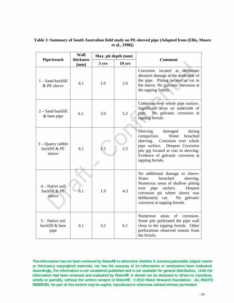
In a later Australian study DIP samples were buried in an aggressive soil environment on the South Australian coast close to Adelaide. Each sample had an un-insulated brass-tapping ferrule fitted to assess the effectiveness of PE sleeving against galvanic corrosion (Ellis, Moore et al., 1998). Pipe/tapping assemblies with and without PE sleeving were installed at the test site. The soil environment at the test site was classified as severely corrosive based on resistivity, pH measurements and testing for the presence of sulphate reducing bacteria. The ground water table at the site was generally below the pipe burial depth, but in winter the whole area was submerged. Sets of pipes were exhumed for examination, 5 and 10 years after their installation at the test site. The results of this study are summarised in Table 3.
The results from the South Australian field experiments suggest that:
§ In an aggressive environment, PE sleeving can reduce external corrosion in DI pipe provided that it is free from slits or damage.
§ The use of angular (sharp) backfill can cause damage to the sleeving, and hence increase corrosion.
§ Well-draining backfill (sand) can reduce the corrosion rate compared to an installation in native aggressive soil.
§ PE sleeving can reduce galvanic corrosion at service connections provided that it is free from damage.
It is interesting to note that in pipe/trench 3 and 4, water had breached the PE sleeve, but the maximum corrosion pit depth was still less than that for an unprotected pipe in the same trench. This may indicate that, as suggested previously by Malazio, oxygen depletion from cathodic reactions in water logged conditions reduces the corrosion rate, notwithstanding the water table being below the pipe for part of the year (Malizio, 1986).
In support of the South Australian and Hunter Region studies, the Melbourne and Metropolitan Board of Works (MMBW1980, 1980; MMBW1981, 1981) concluded that PE sleeving is also highly efficient in mitigating the effects of stray current pick-up. Whilst the work was primarily concerned with impressed DC currents, it was proposed that the mitigation also benefits the resistance to the galvanic couple set up between copper water services and iron pipe (Table 2) (Ferguson and Nicholas, 1983).
These observations confirm the effective corrosion protection of PE sleeving in corrosive soil environments. Whilst pipe failures have been reported in the Hunter Region, exhumation revealed that in all cases, failure was due to the removal of sleeving at service connections, and galvanic corrosion between copper services and iron pipes (Ferguson and Nicholas, 1983).
In a later Australian study DIP samples were buried in an aggressive soil environment on the South Australian coast close to Adelaide. Each sample had an un-insulated brass-tapping ferrule fitted to assess the effectiveness of PE sleeving against galvanic corrosion (Ellis, Moore et al., 1998). Pipe/tapping assemblies with and without PE sleeving were installed at the test site. The soil environment at the test site was classified as severely corrosive based on resistivity, pH measurements and testing for the presence of sulphate reducing bacteria. The ground water table at the site was generally below the pipe burial depth, but in winter the whole area was submerged. Sets of pipes were exhumed for examination, 5 and 10 years after their installation at the test site. The results of this study are summarised in Table 3.
This information has not been reviewed by WaterRF to determine whether it contains patentable subject matter or third-party copyrighted materials, nor has the accuracy of its information or conclusions been evaluated. Accordingly, the information is not considered published and is not available for general distribution. Until the information had been reviewed and evaluated by WaterRF, it should not be disclosed to others to reproduce, wholly or partially, without the written consent of WaterRF. ©2010 Water Research Foundation. ALL RIGHTS RESERVED. No part of this content may be copied, reproduced or otherwise utilized without permission - 17 -
The results from the South Australian field experiments suggest that:
§ In an aggressive environment, PE sleeving can reduce external corrosion in DI pipe provided that it is free from slits or damage.
§ The use of angular (sharp) backfill can cause damage to the sleeving, and hence increase corrosion.
§ Well-draining backfill (sand) can reduce the corrosion rate compared to an installation in native aggressive soil.
§ PE sleeving can reduce galvanic corrosion at service connections provided that it is free from damage.
It is interesting to note that in pipe/trench 3 and 4, water had breached the PE sleeve, but the maximum corrosion pit depth was still less than that for an unprotected pipe in the same trench. This may indicate that, as suggested previously by Malazio, oxygen depletion from cathodic reactions in water logged conditions reduces the corrosion rate, notwithstanding the water table being below the pipe for part of the year (Malizio, 1986).
In support of the South Australian and Hunter Region studies, the Melbourne and Metropolitan Board of Works (MMBW1980, 1980; MMBW1981, 1981) concluded that PE sleeving is also highly efficient in mitigating the effects of stray current pick-up. Whilst the work was primarily concerned with impressed DC currents, it was proposed that the mitigation also benefits the resistance to the galvanic couple set up between copper water services and iron pipe (Ferguson and Nicholas, 1983).
This information has not been reviewed by WaterRF to determine whether it contains patentable subject matter or third-party copyrighted materials, nor has the accuracy of its information or conclusions been evaluated. Accordingly, the information is not considered published and is not available for general distribution. Until the information had been reviewed and evaluated by WaterRF, it should not be disclosed to others to reproduce, wholly or partially, without the written consent of WaterRF. ©2010 Water Research Foundation. ALL RIGHTS RESERVED. No part of this content may be copied, reproduced or otherwise utilized without permission - 18 -
Table 2: Exhumation observation of PE sleeved Cast Iron pipe in Hunter Region, NSW (adapted from (Ferguson and Nicholas, 1983))
Exposure time (years) Soil type pH Redox
(mV) Sulphides Resistivity
(ohm.cm) Pipe and sleeving condition
6 Dry - - -
4000
Slight rust film on pipe and sleeving. No pitting on pipe
6 Brown sand with clay
7.4 +18 Negative 550
Sleeving discoloured by rust. Thin rust scale on portions of the pipe. Otherwise pipe in perfect condition
6
Moist medium brown plastic clay
7.3 -120 Positive 340
Thin rust film on bottom of pipe. No pitting and no evidence of graphitisation
6
Brown clay, sand and silt mixed with blue clay muck
7.2 -138 Positive 320 Very thin film of corrosion products on part of the pipe
8 Dar grey, silty clay, saturated
7.5 +168 Trace 310
Discolouration of sleeving. Much of the outer surface of the pipe covered with red-black scale. No measurable pitting
8 Water saturated grey clay
7.7 +162 Positive 300
Pipe covered with scale. Severe discolouration of sleeving. Intrusion of clay and small pit at intrusion
15
Water saturated grey sand and silt
7.3 +80 Trace 480
Severe discolouration of sleeving. Thin scale over most of the surface. No measurable pitting
This information has not been reviewed by WaterRF to determine whether it contains patentable subject matter or third-party copyrighted materials, nor has the accuracy of its information or conclusions been evaluated. Accordingly, the information is not considered published and is not available for general distribution. Until the information had been reviewed and evaluated by WaterRF, it should not be disclosed to others to reproduce, wholly or partially, without the written consent of WaterRF. ©2010 Water Research Foundation. ALL RIGHTS RESERVED. No part of this content may be copied, reproduced or otherwise utilized without permission - 19 -
Table 3: Summary of South Australian field study on PE-sleeved pipe (Adapted from (Ellis, Moore et al., 1998))
Pipe/trench Wall
thickness (mm)
Max. pit depth (mm) Comment
5 yrs 10 yrs
1 – Sand backfill & PE sleeve 6.1 1.0 2.0
Corrosion located at deliberate abrasion damage at the underside of the pipe. Pitting located at cut in the sleeve. No galvanic corrosion at the tapping ferrule.
2 – Sand backfill & bare pipe 6.1. 3.0 5.2
Corrosion over whole pipe surface. Significant areas on underside of pipe. No galvanic corrosion at tapping ferrule.
3 – Quarry rubble backfill & PE
sleeve 6.1 1.5 2.5
Sleeving damaged during compaction. Water breached sleeving. Corrosion over whole pipe surface. Deepest Corrosion pits not
located at cuts in sleeving. Evidence of galvanic corrosion at tapping ferrule.
4 – Native soil backfill & PE
sleeve 6.1 1.9 4.3
No additional damage to sleeve. Water breached sleeving. Numerous areas of shallow pitting over pipe surface. Deepest corrosion pit where sleeve was deliberately cut. No galvanic corrosion at tapping ferrule.
5 – Native soil backfill & bare
pipe 6.1 3.2 6.1
Numerous areas of corrosion. Some pits perforated the pipe wall close to the tapping ferrule. Other perforations observed remote from the ferrule.
This information has not been reviewed by WaterRF to determine whether it contains patentable subject matter or third-party copyrighted materials, nor has the accuracy of its information or conclusions been evaluated. Accordingly, the information is not considered published and is not available for general distribution. Until the information had been reviewed and evaluated by WaterRF, it should not be disclosed to others to reproduce, wholly or partially, without the written consent of WaterRF. ©2010 Water Research Foundation. ALL RIGHTS RESERVED. No part of this content may be copied, reproduced or otherwise utilized without permission - 20 -
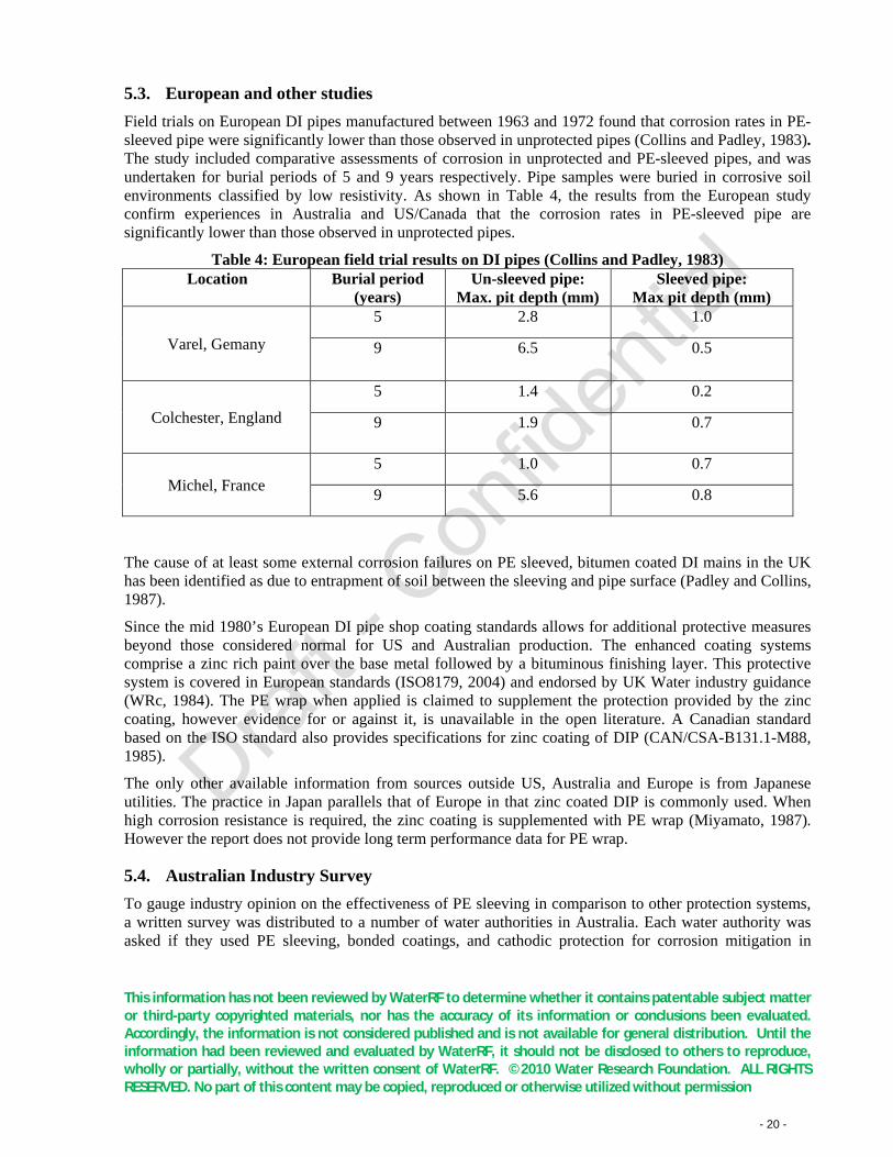
5.3. European and other studies Field trials on European DI pipes manufactured between 1963 and 1972 found that corrosion rates in PE-sleeved pipe were significantly lower than those observed in unprotected pipes (Collins and Padley, 1983). The study included comparative assessments of corrosion in unprotected and PE-sleeved pipes, and was undertaken for burial periods of 5 and 9 years respectively. Pipe samples were buried in corrosive soil environments classified by low resistivity. As shown in Table 4, the results from the European study confirm experiences in Australia and US/Canada that the corrosion rates in PE-sleeved pipe are significantly lower than those observed in unprotected pipes.
Table 4: European field trial results on DI pipes (Collins and Padley, 1983) Location
Burial period
(years) Un-sleeved pipe:
Max. pit depth (mm) Sleeved pipe:
Max pit depth (mm)
Varel, Gemany
5 2.8 1.0
9 6.5 0.5
Colchester, England
5 1.4 0.2
9 1.9 0.7
Michel, France 5 1.0 0.7
9 5.6 0.8
The cause of at least some external corrosion failures on PE sleeved, bitumen coated DI mains in the UK has been identified as due to entrapment of soil between the sleeving and pipe surface (Padley and Collins, 1987).
Since the mid 1980’s European DI pipe shop coating standards allows for additional protective measures beyond those considered normal for US and Australian production. The enhanced coating systems comprise a zinc rich paint over the base metal followed by a bituminous finishing layer. This protective system is covered in European standards (ISO8179, 2004) and endorsed by UK Water industry guidance (WRc, 1984). The PE wrap when applied is claimed to supplement the protection provided by the zinc coating, however evidence for or against it, is unavailable in the open literature. A Canadian standard based on the ISO standard also provides specifications for zinc coating of DIP (CAN/CSA-B131.1-M88, 1985).
The only other available information from sources outside US, Australia and Europe is from Japanese utilities. The practice in Japan parallels that of Europe in that zinc coated DIP is commonly used. When high corrosion resistance is required, the zinc coating is supplemented with PE wrap (Miyamato, 1987). However the report does not provide long term performance data for PE wrap.
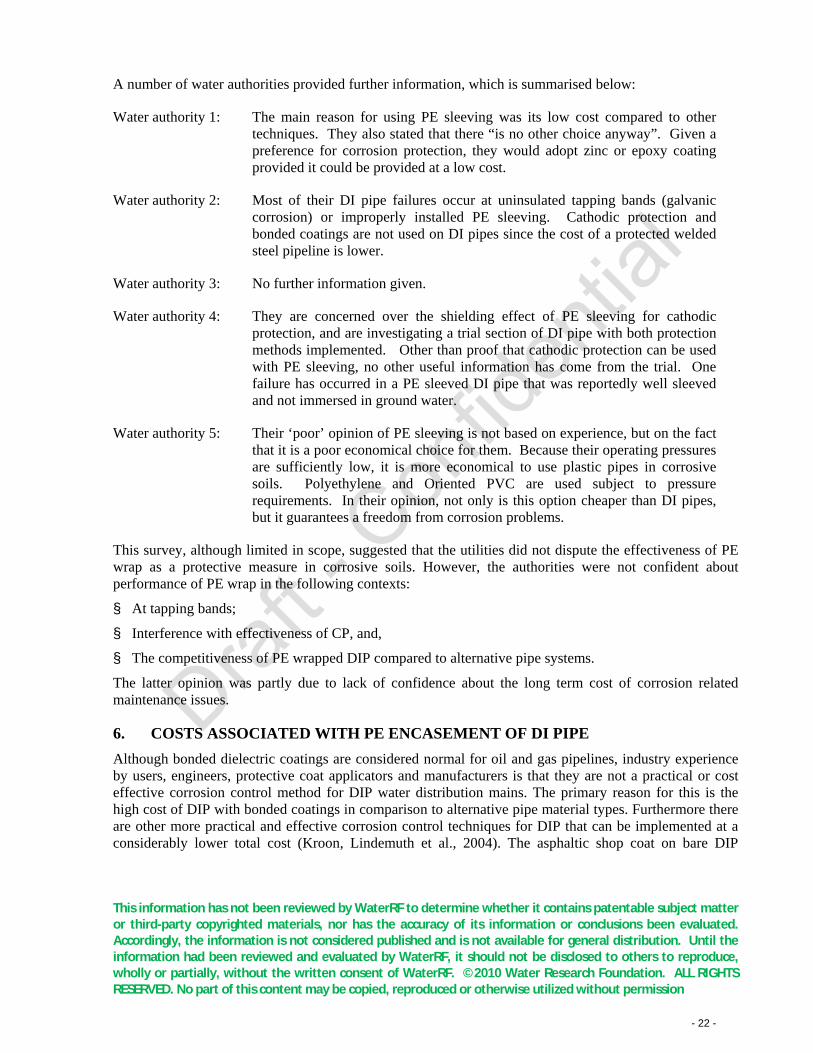
5.4. Australian Industry Survey To gauge industry opinion on the effectiveness of PE sleeving in comparison to other protection systems, a written survey was distributed to a number of water authorities in Australia. Each water authority was asked if they used PE sleeving, bonded coatings, and cathodic protection for corrosion mitigation in
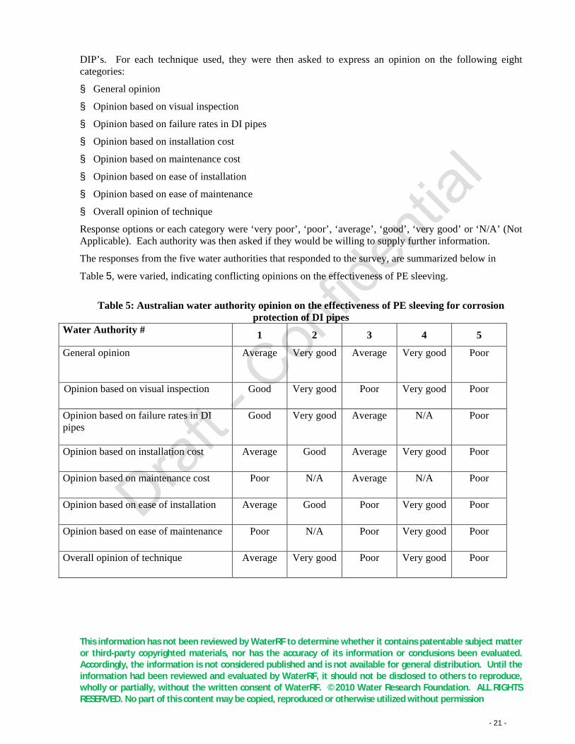
This information has not been reviewed by WaterRF to determine whether it contains patentable subject matter or third-party copyrighted materials, nor has the accuracy of its information or conclusions been evaluated. Accordingly, the information is not considered published and is not available for general distribution. Until the information had been reviewed and evaluated by WaterRF, it should not be disclosed to others to reproduce, wholly or partially, without the written consent of WaterRF. ©2010 Water Research Foundation. ALL RIGHTS RESERVED. No part of this content may be copied, reproduced or otherwise utilized without permission - 21 -
DIP’s. For each technique used, they were then asked to express an opinion on the following eight categories:
§ General opinion
§ Opinion based on visual inspection
§ Opinion based on failure rates in DI pipes
§ Opinion based on installation cost
§ Opinion based on maintenance cost
§ Opinion based on ease of installation
§ Opinion based on ease of maintenance
§ Overall opinion of technique
Response options or each category were ‘very poor’, ‘poor’, ‘average’, ‘good’, ‘very good’ or ‘N/A’ (Not Applicable). Each authority was then asked if they would be willing to supply further information.
The responses from the five water authorities that responded to the survey, are summarized below in
Table 5, were varied, indicating conflicting opinions on the effectiveness of PE sleeving.
Table 5: Australian water authority opinion on the effectiveness of PE sleeving for corrosion
protection of DI pipes Water Authority # 1 2 3 4 5
General opinion
Average
Very good Average Very good Poor
Opinion based on visual inspection
Good
Very good Poor Very good Poor
Opinion based on failure rates in DI pipes
Good
Very good Average N/A Poor
Opinion based on installation cost
Average
Good Average Very good Poor
Opinion based on maintenance cost
Poor N/A Average N/A Poor
Opinion based on ease of installation
Average Good Poor Very good Poor
Opinion based on ease of maintenance
Poor N/A Poor Very good Poor
Overall opinion of technique Average Very good Poor Very good Poor
This information has not been reviewed by WaterRF to determine whether it contains patentable subject matter or third-party copyrighted materials, nor has the accuracy of its information or conclusions been evaluated. Accordingly, the information is not considered published and is not available for general distribution. Until the information had been reviewed and evaluated by WaterRF, it should not be disclosed to others to reproduce, wholly or partially, without the written consent of WaterRF. ©2010 Water Research Foundation. ALL RIGHTS RESERVED. No part of this content may be copied, reproduced or otherwise utilized without permission - 22 -
A number of water authorities provided further information, which is summarised below:
Water authority 1: The main reason for using PE sleeving was its low cost compared to other techniques. They also stated that there “is no other choice anyway”. Given a preference for corrosion protection, they would adopt zinc or epoxy coating provided it could be provided at a low cost.
Water authority 2: Most of their DI pipe failures occur at uninsulated tapping bands (galvanic corrosion) or improperly installed PE sleeving. Cathodic protection and bonded coatings are not used on DI pipes since the cost of a protected welded steel pipeline is lower.
Water authority 3: No further information given.
Water authority 4: They are concerned over the shielding effect of PE sleeving for cathodic protection, and are investigating a trial section of DI pipe with both protection methods implemented. Other than proof that cathodic protection can be used with PE sleeving, no other useful information has come from the trial. One failure has occurred in a PE sleeved DI pipe that was reportedly well sleeved and not immersed in ground water.
Water authority 5: Their ‘poor’ opinion of PE sleeving is not based on experience, but on the fact that it is a poor economical choice for them. Because their operating pressures are sufficiently low, it is more economical to use plastic pipes in corrosive soils. Polyethylene and Oriented PVC are used subject to pressure requirements. In their opinion, not only is this option cheaper than DI pipes, but it guarantees a freedom from corrosion problems.
This survey, although limited in scope, suggested that the utilities did not dispute the effectiveness of PE wrap as a protective measure in corrosive soils. However, the authorities were not confident about performance of PE wrap in the following contexts:
§ At tapping bands;
§ Interference with effectiveness of CP, and,
§ The competitiveness of PE wrapped DIP compared to alternative pipe systems.
The latter opinion was partly due to lack of confidence about the long term cost of corrosion related maintenance issues.
6. COSTS ASSOCIATED WITH PE ENCASEMENT OF DI PIPE Although bonded dielectric coatings are considered normal for oil and gas pipelines, industry experience by users, engineers, protective coat applicators and manufacturers is that they are not a practical or cost effective corrosion control method for DIP water distribution mains. The primary reason for this is the high cost of DIP with bonded coatings in comparison to alternative pipe material types. Furthermore there are other more practical and effective corrosion control techniques for DIP that can be implemented at a considerably lower total cost (Kroon, Lindemuth et al., 2004). The asphaltic shop coat on bare DIP
This information has not been reviewed by WaterRF to determine whether it contains patentable subject matter or third-party copyrighted materials, nor has the accuracy of its information or conclusions been evaluated. Accordingly, the information is not considered published and is not available for general distribution. Until the information had been reviewed and evaluated by WaterRF, it should not be disclosed to others to reproduce, wholly or partially, without the written consent of WaterRF. ©2010 Water Research Foundation. ALL RIGHTS RESERVED. No part of this content may be copied, reproduced or otherwise utilized without permission - 23 -
provides a basic level of protection while PE wrap, CP with sacrificial anode, and CP with an impressed current, provide incrementally greater levels of protection. The zinc coating provided in Europe and Japan is another level of available protection. The key to determining which methodology to use requires a good understanding of the likelihood and consequences of corrosion.
In a comparison of life cycle costs with cathodic protection, a detailed cost assessment of PE sleeving was conducted by Craft (Craft, 1996). The case study examined the actual costs involved in installing 1.6 kilometres of 765 mm diameter DI transmission main in an urban location. The cost to install a PE encased system in this particular application was quoted to be US$6,221.60. A CP system with tape wrapped pipe, joint bonding for electrical continuity, a test station, a zinc reference electrode and 13 anode beds, each with ten 32 lb anodes was costed at US$114,100; i.e., about 18 times the cost PE wrap protection. With ongoing operational costs (annual field voltage readings) maintenance and anode replacement costs, estimated at US$45,200 per annum, the projected cost over a 100 year lifespan was over US$2 million. If no additional cost is incurred after installation of the PE sleeving, its 100-year life cycle cost is the initial installation cost of US$6,200. Therefore, based on these estimates for this case, the 100 year life cycle cost of a sacrificial anode cathodic protection system is 370-times greater than that of PE sleeving.
In a DIPRA publication on PE encasement (DIPRA, undated), a report written by the US Corps of Engineers in 1985 indicates that the cost of installing an impressed current cathodic protection system on a 12 inch DIP was 5-times the cost of PE encasement. However, the cost estimates do not incorporate the added ongoing maintenance costs incurred with using cathodic protection systems.
In a more recent study, the basic cost of DI pipe and the added on-costs of PE wrap and CP systems depending on the required CP current density for 100 year life extension were estimated for 30, 42 and 54 inch pipelines (Kroon, 2006). The costs estimated from this study are summarized in Appendix 1.
The cost analysis indicates that over a 100 year life cycle, while the cost of PE wrap was under 0.6% of base DIP construction cost, the combined PE wrap and CP cost was less than 4% of the initial cost. This was on the basis that PE wrap will not require maintenance over the period. Monitoring corrosion through pipe potential measurements adds 2.2% to the cost for electrical connections over joints and test stations every 2000 feet (666 m) for annual monitoring and maintenance. Supplementing the protection afforded by PE wrap with CP adds a further 0.6% - 1.1% to the cost depending on the CP system, sacrificial anode or impressed current. The analysis also indicated that when CP is applied without PE wrap, the impressed current CP systems required for the higher current density adds 10.2% to the cost.
The 2006 study by Kroon appears to be the most relevant available, which compares the costs of PE wrap and CP corrosion protection systems, while projecting their future costs over the anticipated service life of the pipe system. However, it should also be noted that costing is on the basis that PE does not deteriorate over the design lifetime, and has no allowance for possible increase maintenance costs through failures in the PE wrap. The observation from Szeliga and Simpson suggest that installation defects in PE sleeving may not be avoided completely and this means that there is potential for premature failure of PE wrapped DIP’s (Szeliga and Simpson, 2001). However, as little data is available to allow failure rate prediction of wrapped DIP’s it is difficult to carry out an life cycle cost (LCC) analysis in which the expected failure rate (and hence pipe replacement cost) in a PE-sleeved pipeline is compared with the maintenance cost of a cathodically protected pipeline.
This information has not been reviewed by WaterRF to determine whether it contains patentable subject matter or third-party copyrighted materials, nor has the accuracy of its information or conclusions been evaluated. Accordingly, the information is not considered published and is not available for general distribution. Until the information had been reviewed and evaluated by WaterRF, it should not be disclosed to others to reproduce, wholly or partially, without the written consent of WaterRF. ©2010 Water Research Foundation. ALL RIGHTS RESERVED. No part of this content may be copied, reproduced or otherwise utilized without permission - 24 -
7. RECYCLED IRON IN DI PIPE MANUFACTURE The practice of including recycled iron in pipe manufacture has been raised by Woodcock (BoR, 2009). In his submission to the review by the Bureau, Woodcock states that older ductile iron pipes were made with higher pig iron content (“pure iron”) and recent pipe is predominantly made from scrap iron and steel. The scrap steel can contain chromium, nickel, molybdenum, tungsten, vanadium, titanium, etc., and some DIP made today is extremely sensitive to corrosion while some are almost corrosion resistant. The presence of the trace metals and their carbides are believed to be a possible source of this wide variation in corrosion sensitivity. DIP is no longer an “iron product” with just Fe, Mn, Si, S, and P. Woodcock further explained how corrosion activity can be initiated at the pipe surface when the asphaltic shop coating is damaged. The corrosion does not have to be driven by interaction with soil, but through galvanic action between different sections of the same pipe. The only requirement is the presence of moisture to act as an electrolyte. Therefore breaches in PE wrap, apart from inducing corrosion from interaction with soil, will contribute to purely galvanic corrosion in new ductile iron pipe at sites remote from the site of damage to PE wrap.
8. CONCLUSION The literature and utility experience indicates PE wrap is an effective protection method for DI pipe in corrosive environments when installed without breaches to the PE film. However in practice this does not occur even though the installation specifications and procedures are detailed in numerous standards and industry guidelines. The lapses in protection performance is due principally to ingress of moisture from undetected damage to the wrap and from sealing breaches at joints and appurtenances such as service tappings, branch off-takes and valve insertions.
Although the industry documents acknowledge that moisture ingress is unavoidable, especially during installation, it is suggested that oxygen in the trapped water will ultimately be consumed by corrosion, arresting continued corrosive action. This is disputed by industry practitioners and continues to be a controversial issue.
Deterioration of the PE wrap material in the soil burial environment from chemical or microbial action has not been recorded at test burial sites or at failure excavations. The samples at test sites are approaching 60 years while failure sites are aged around 40 years at best. Any breaches at failure sites have been attributed to damage at installation from poor workmanship or subsequent attachment of appurtenances. However the wrap is continuously stressed in service due to the weight of the pipe and from shrink/swell movement of soil. Although PE is able to stress relieve over time, the long term effects of burial stresses needs to be investigated. The long term effect of microbiological action also warrants investigation. While literature points to PE (LDPE, LLDPE, HDPE, CLHDPE) is bio-inert, some studies point to possible changes to PE structure by some fungi under specific conditions.
Another aspect that warrants investigation is the adhesive properties of sealing tapes used for PE wrap installation. Due to the inert properties of PE, the adhesion between the tape and PE film is purely electrostatic, and not chemical. Failure or diminution of the adhesive strength with age, especially under moist or water logged conditions is possible. While literature does not record the condition of the sealing tape at excavations, long term adhesive properties of sealing tapes in soil environments should be studied.
An issue that encompasses all the factors discussed is microbial induced corrosion (MIC). While MIC in cast iron is well documented, PE wrap protected DI pipe is considered safe from MIC on account of the
This information has not been reviewed by WaterRF to determine whether it contains patentable subject matter or third-party copyrighted materials, nor has the accuracy of its information or conclusions been evaluated. Accordingly, the information is not considered published and is not available for general distribution. Until the information had been reviewed and evaluated by WaterRF, it should not be disclosed to others to reproduce, wholly or partially, without the written consent of WaterRF. ©2010 Water Research Foundation. ALL RIGHTS RESERVED. No part of this content may be copied, reproduced or otherwise utilized without permission - 25 -
isolating barrier. However the ingress of moisture and subsequent depletion of oxygen in the confined space creates an environment that is suited for MIC such as SRB. The MIC action may not be limited to DI, as microbial action on polymers under anaerobic conditions is also a possibility.
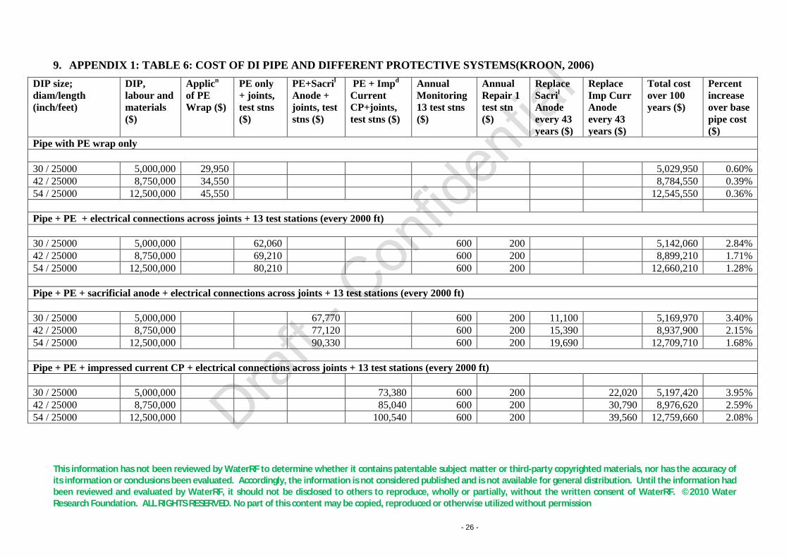
This information has not been reviewed by WaterRF to determine whether it contains patentable subject matter or third-party copyrighted materials, nor has the accuracy of its information or conclusions been evaluated. Accordingly, the information is not considered published and is not available for general distribution. Until the information had been reviewed and evaluated by WaterRF, it should not be disclosed to others to reproduce, wholly or partially, without the written consent of WaterRF. ©2010 Water Research Foundation. ALL RIGHTS RESERVED. No part of this content may be copied, reproduced or otherwise utilized without permission - 26 -
9. APPENDIX 1: TABLE 6: COST OF DI PIPE AND DIFFERENT PROTECTIVE SYSTEMS(KROON, 2006) DIP size; diam/length (inch/feet)
DIP, labour and materials ($)
Applicn of PE Wrap ($)
PE only + joints, test stns ($)
PE+Sacril Anode + joints, test stns ($)
PE + Impd Current CP+joints, test stns ($)
Annual Monitoring 13 test stns ($)
Annual Repair 1 test stn ($)
Replace Sacril Anode every 43 years ($)
Replace Imp Curr Anode every 43 years ($)
Total cost over 100 years ($)
Percent increase over base pipe cost ($)
Pipe with PE wrap only
30 / 25000 5,000,000 29,950
5,029,950 0.60% 42 / 25000 8,750,000 34,550
8,784,550 0.39%
54 / 25000 12,500,000 45,550 12,545,550 0.36%
Pipe + PE + electrical connections across joints + 13 test stations (every 2000 ft)
30 / 25000 5,000,000 62,060
600 200
5,142,060 2.84% 42 / 25000 8,750,000 69,210
600 200
8,899,210 1.71%
54 / 25000 12,500,000 80,210 600 200 12,660,210 1.28%
Pipe + PE + sacrificial anode + electrical connections across joints + 13 test stations (every 2000 ft)
30 / 25000 5,000,000
67,770
600 200 11,100
5,169,970 3.40% 42 / 25000 8,750,000
77,120
600 200 15,390
8,937,900 2.15%
54 / 25000 12,500,000 90,330 600 200 19,690 12,709,710 1.68%
Pipe + PE + impressed current CP + electrical connections across joints + 13 test stations (every 2000 ft)
30 / 25000 5,000,000
73,380 600 200 22,020 5,197,420 3.95% 42 / 25000 8,750,000
85,040 600 200 30,790 8,976,620 2.59%
54 / 25000 12,500,000 100,540 600 200 39,560 12,759,660 2.08%
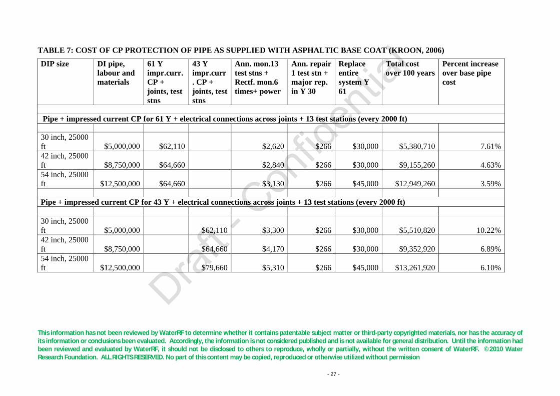
This information has not been reviewed by WaterRF to determine whether it contains patentable subject matter or third-party copyrighted materials, nor has the accuracy of its information or conclusions been evaluated. Accordingly, the information is not considered published and is not available for general distribution. Until the information had been reviewed and evaluated by WaterRF, it should not be disclosed to others to reproduce, wholly or partially, without the written consent of WaterRF. ©2010 Water Research Foundation. ALL RIGHTS RESERVED. No part of this content may be copied, reproduced or otherwise utilized without permission - 27 -
TABLE 7: COST OF CP PROTECTION OF PIPE AS SUPPLIED WITH ASPHALTIC BASE COAT (KROON, 2006)
DIP size DI pipe, labour and materials
61 Y impr.curr. CP + joints, test stns
43 Y impr.curr. CP + joints, test stns
Ann. mon.13 test stns + Rectf. mon.6 times+ power
Ann. repair 1 test stn + major rep. in Y 30
Replace entire system Y 61
Total cost over 100 years
Percent increase over base pipe cost
Pipe + impressed current CP for 61 Y + electrical connections across joints + 13 test stations (every 2000 ft)
30 inch, 25000 ft $5,000,000 $62,110 $2,620 $266 $30,000 $5,380,710 7.61% 42 inch, 25000 ft $8,750,000 $64,660
$2,840 $266 $30,000 $9,155,260 4.63%
54 inch, 25000 ft $12,500,000 $64,660 $3,130 $266 $45,000 $12,949,260 3.59%
Pipe + impressed current CP for 43 Y + electrical connections across joints + 13 test stations (every 2000 ft)
30 inch, 25000 ft $5,000,000 $62,110 $3,300 $266 $30,000 $5,510,820 10.22% 42 inch, 25000 ft $8,750,000 $64,660 $4,170 $266 $30,000 $9,352,920 6.89% 54 inch, 25000 ft $12,500,000 $79,660 $5,310 $266 $45,000 $13,261,920 6.10%
This information has not been reviewed by WaterRF to determine whether it contains patentable subject matter or third-party copyrighted materials, nor has the accuracy of its information or conclusions been evaluated. Accordingly, the information is not considered published and is not available for general distribution. Until the information had been reviewed and evaluated by WaterRF, it should not be disclosed to others to reproduce, wholly or partially, without the written consent of WaterRF. ©2010 Water Research Foundation. ALL RIGHTS RESERVED. No part of this content may be copied, reproduced or otherwise utilized without permission - 28 -
10. REFERENCES (2005). Handbook of Biodegradable Polymers
Albertsson, A. C. and Z. G. Banhidi (1980). "Microbial and Oxidative Effects in Degradation of Polyethylene."
. Abington Hall, Abington, Cambridge, CB21 6AH, UK, Woodhead Publishing Limited,.
Journal of Applied Polymer Science
Albertsson, A. C. and S. Karlsson (1988). "The 3 Stages in Degradation of Polymers - Polyethylene as a Model Substance."
25(8): 1655-1671.
Journal of Applied Polymer Science
Albertsson, A. C. and S. Karlsson (1990). "The Influence of Biotic and Abiotic Environments on the Degradation of Polyethylene."
35(5): 1289-1302.
Progress in Polymer Science
ANSI/AWWA (1999). Polyethyllene Encasement for Ductile Iron Pipelines and Fittings.
15(2): 177-192.
C105/A21.5
AS3680 (1989). Polyethylene sleeving to ductile iron pipes.
. A. N. S. Institute. Washington D.C, American National Standards Institute.
3680
AS3681 (1989). Guidelines for the application of Polyethylene sleeving to ductile iron pipelines and fittings.
. A. Standards. Canberra, Australian Standards.
3681
AS3681 (1989).
. A. Standards. Canberra, Australian Standards.
Guidelines for the application of Polyethylene sleeving to ductile iron pipelines and fittings. 3681
Ash, G. L. (1998). "Polyethylene encasement of buried conduit."
. A. Standards. Canberra, Australian Standards.
Pipelines in the Constructed Environment
Bell, G. E. C., V. Pilko, et al. (2009).
: 180-186.
Managing and Monitoring Internal Corrosion on Ductile Iron Pipe Force Mains
Bonds, R. W. (1995). "Polyethylene encasement and the 1993 revision of ANSI/AWWA C105/A21.5 standard."
. Pipelines 2009: Infrastructure's Hidden Assets, San Diego, California, ASCE.
Advances in Underground Pipeline Engineering
Bonds, R. W., L. M. Barnard, et al. (2005). "Corrosion and corrosion control of iron pipe: 75 years of research."
: 322-333.
Journal American Water Works Association
Bonhomme, S., A. Cuer, et al. (2003). "Environmental biodegradation of polyethylene."
97(6): 88-98.
Polymer Degradation and Stability
BoR (2009). Review of Bureau of Reclamation’s Corrosion Prevention Standards for ductile Iron Pipe. Washington, D.C., National Research Council of the National Academies
81(3): 441-452.
Brander, R. (2001). Water pipe materials in Calgary, 1970-2000. American Water Works Association (AWWA) 2001 Infrastructure Conference
BS6076 (1996). Specification for polymeric film for use as a protective sleeving for buried iron pipes and fittings (for site and factory application).
. Orlando, FLA, USA, AWWA.
6076
CAN/CSA-B131.1-M88 (1985). External Zinc-Coating of Ductile Iron Pipe.
. B. S. Institution, British Standards Institution.
CAN/CSA-B131.1-M88
Caproco, Corrosion, et al. (1985). Underground corrosion of water pipes in Canadian cities – case, the city of Calgary: Final Report. Calgary, Energy Mines and Resources and Canada Centre for Minerals and Energy.
C. Standards.
This information has not been reviewed by WaterRF to determine whether it contains patentable subject matter or third-party copyrighted materials, nor has the accuracy of its information or conclusions been evaluated. Accordingly, the information is not considered published and is not available for general distribution. Until the information had been reviewed and evaluated by WaterRF, it should not be disclosed to others to reproduce, wholly or partially, without the written consent of WaterRF. ©2010 Water Research Foundation. ALL RIGHTS RESERVED. No part of this content may be copied, reproduced or otherwise utilized without permission - 29 -
Carpenter, R. and R. C. Conner (2003). The versatility of ductile iron pipe in trenchless construction
Colin, G., J. D. Cooney, et al. (1976). "Some Factors influencing Microbial Degradation of Polyethylene."
. International Conference on Pipeline Engineering and Construction 2003: New pipeline technologies, security and safety, Baltimore, MD, USA, ASCE.
International Biodeterioration Bulletin
Collins, H. H. and T. J. Padley (1983).
12(3): 67-71.
Protection of spun iron pipes against corrosion by soils
Crabtree, D. W. and M. R. Breslin (2008). "Case History: Investigating Polyethylene-Encased Ductile Iron Pipelines."
. 5th International Conference on Internal and External Protection of Pipes, Innsbruck, Austria.
Materials Performance
Crabtree, D. W., M. R. Breslin, et al. (2007). Assessing Polyethylene Encased Ductile Iron Pipelines.
47(10): 49-53.
Pipelines 2007: Advances and Experiences with Trenchless Pipeline Projects
Craft, G. (1996). "Corrosion protection--a cost comparison."
. M. N. Lynn Osborn. Boston, Massachusetts, USA, ASCE. 252: 95.
US Piper
Davis, P., I. Allan, et al. (2003). Identifying Trends In Cast Iron Pipe Failure With GIS Maps Of Soil Environments.
65(2): 14-17.
Pipes 2003 - Back to Basics: Design and Innovation
De Silva, D. (2010). Estimated from 08 Apr 2010, 12:00 hrs, 16 breaks; 24 hrs 32 breaks; for 3 utils combined (CWW, SEW, YVW) >75/day.
. Wagga Wagga, NSW, Australia.
DIPRA (1985). Underground Corrosion of Water Pipes in Canadian Cities; Case: The City of Calgary. Birmingham, Alabama, DIPRA.
DIPRA. (2007, 05/2007). "Effective, Economical Protection for Ductile Iron Pipe In Corrosive Environments." Retrieved 04/02/2009, 2008, from ://www.dipra.com/pdf/polyEncasement.pdf. Dolezel, B. (1967). "Corrosion of plastic materials and rubbers." British Journal of Plastic Surgery
Eggins, H. O. W., J. Mills, et al. (1971). Biodeterioration and Biodegradation of synthetic Polymers.
49: 105-113.
Microbial aspects of pollution
Ellis, D., G. Moore, et al. (1998).
. G. Sykes and F. A. Skinner. London, Academic Press.
Environmental Corrosion Testing of Ductile Iron Water Pipes
Ferguson, P. and D. Nicholas (1983).
. Corrosion and Prevention 98, Hobart, Australia, Australasian Corrosion Association.
Corrosion Protection of Buried Cast Iron Water Mains
Gummow, R. A. (1984). "The Corrosion of Municipal Iron Watermains."
. ACA Conference, Sydney, Australia, Corrosion Australia.
Materials Performance
Gummow, R. A. (2000). "CP corrosion control of municipal infrastructure."
23(3): 39-42.
Materials Performance
Hakkarainen, M. and A.-C. Albertsson (2004). Environmental Degradation of Polyethylene.
39(2): 26-32.
Advances In Polymer Science
Horton, M. (2008). Polyethylene encasement as an asset preservation method for ductile iron pipe.
, Springer Berlin / Heidelberg. 169: 177-200.
Pipeline Asset Management: Maximizing Performance of Our Pipeline Infrastructure
ISO8179 (2004). ISO 8179: Ductile iron pipes -- External zinc-based coating -- Part 1: Metallic zinc with finishing layer.
. S. R. Sanjiv Gokhale. Atlanta, GA, ASCE. 321: 101.
8179
ISO8180 (2006). ISO 8180: Ductile iron pipelines -- Polyethylene sleeving for site application.
. ISO.
8180.
This information has not been reviewed by WaterRF to determine whether it contains patentable subject matter or third-party copyrighted materials, nor has the accuracy of its information or conclusions been evaluated. Accordingly, the information is not considered published and is not available for general distribution. Until the information had been reviewed and evaluated by WaterRF, it should not be disclosed to others to reproduce, wholly or partially, without the written consent of WaterRF. ©2010 Water Research Foundation. ALL RIGHTS RESERVED. No part of this content may be copied, reproduced or otherwise utilized without permission - 30 -
ISO.
Jakobs, J. A. and F. W. Hewes (1987). "underground corrosion of water pipes in Calgary, Canada." Materials Performance
Jen-Hao, L. and A. Schawartz (1961).
26(5): 42-49.
Kunststoffe
Kershaw, M. J. and N. J. Talbot (1998). "Hydrophobins and repellents: Proteins with fundamental roles in fungal morphogenesis."
51: 317.
Fungal Genetics and Biology
Kestelman, V. N., V. L. Yarovenko, et al. (1972). "The corrosion of polymeric materials under the conditions of the micro-biological synthesis of enzymes."
23(1): 18-33.
International Biodeterioration Bulletin
Kim, D. Y. and Y. H. Rhee (2003). "Biodegradation of microbial and synthetic polyesters by fungi."
8(1): 15-19.
Applied Microbiology and Biotechnology
Kroon, D. H. (2006). "Life-cycle cost comparions of corrosion protection methods for ductile iron pipe."
61(4): 300-308.
Materials Performance
Kroon, D. H., D. Lindemuth, et al. (2004).
45(5): 44-48.
Advanced corrosion protection solutions for DI pipe
Lary, J. T. (2000). "Corrosion, Not Age, is to Blame for Most Water Main Breaks."
. Pipeline Engineering and Construction: What's on the Horizon?, San Diego, California, USA, ASCE.
WaterWorld
Lary, J. T. (2003).
16(4).
Cathodic protection applications for water pipeline systems
Lary, J. T. (2003).
. New pipeline technologies, security and safety, Baltimore, MD, USA, ASCE.
Cathodic Protection Applications for Water System Piping
Lindemuth, D. and D. Kroon (2006). Ductile Iron Pipe: Proven synergistic corrosion protection.
. International Conference on Pipeline Engineering and Construction 2003: New Pipeline Technologies, Security, and Safety, Baltimore, Maryland, USA, ASCE.
ASCE Pipelines Conference
Lindemuth, D. and D. Kroon (2009). "Case Histories: Cathodic Protection of Pipe Encapsulated in Polyethylene Film."
, ASCE.
Materials Performance
Malizio, A. B. (1986). "Pipe digs show effectiveness of poly sheet encasement."
48(1): 34-39.
Water Engineering and Management
Miller, J. H. (1985). "Polyethylene encasement for protecting underground piping."
133(3): 27-28.
Water and Pollution Control
Mills, J. and H. Eggins (1970). "Growth of thermophilic fungi on oxidation products of polyethylene."
(July/August): 17-18.
International Biodeterioration Bulletin
Miyamato, H. (1987). "Protection of ductile iron pipe against corrosion."
6(1): 13.
Water Supply
MMBW1980 (1980). Corrosion protection of grey and ductile iron pipes, sleeved and unsleeved; Progress Report No. 2. Melbourne, Melbourne Metropolitan Board of Works: 28.
5(3/4): 20-21.
MMBW1981 (1981). Corrosion protection of grey and ductile iron pipes, sleeved and unsleeved; Progress Report No. 3. Melbourne, Melbourne Metropolitan Board of Works: 17.
Padley, T. J. and H. H. Collins (1987). External protection of buried ductile iron pipes by polyethylene sleeving. Seventh International Conference on the Internal and External Protection of Pipes. London, UK, BHRA Fluid Engineering, Cranfield, Bedford: 81-83.

This information has not been reviewed by WaterRF to determine whether it contains patentable subject matter or third-party copyrighted materials, nor has the accuracy of its information or conclusions been evaluated. Accordingly, the information is not considered published and is not available for general distribution. Until the information had been reviewed and evaluated by WaterRF, it should not be disclosed to others to reproduce, wholly or partially, without the written consent of WaterRF. ©2010 Water Research Foundation. ALL RIGHTS RESERVED. No part of this content may be copied, reproduced or otherwise utilized without permission - 31 -
Rajani, B. and Y. Kleiner (2003). "Protecting Ductile-Iron Water Mains: What Protection Method Works Best for What Soil Condition?" Journal of the American Water Works Association
Schiff, M. J. and B. McCollom (1993). "Impressed Current Cathodic Protection of Polyethylene Encased Ductile Iron Pipe."
95(11): 16.
Materials Performance
Seneviratne, G., N. S. Tennakoon, et al. (2006). "LDPE biodegradation by a developed Penicillium–Bacillus biofilm."
32(8): 23-27.
Current Science
Shah, A. A., F. Hasan, et al. (2008). "Biological degradation of plastics: a comprehensive review."
90(1): 20-21.
Biotechnology Advances
Spickelmire, W. S. (2003).
26: 246-265.
Ductile Iron Corrosion Factors to Consider and Why
Szeliga, M. J. (1991).
. International Conference on Pipeline Engineering and Construction 2003: New pipeline technologies, security and safety, Baltimore, Maryland, USA, ASCE.
Corrosion failures in the water industry: case histories
Szeliga, M. J. (2005). "Case histories - Ductile iron pipeline failures."
. Material Peformance Maintenenace, Ottowa, Ontario.
Materials Performance
Szeliga, M. J. (2007). "Analysis of ductile iron corrosion data from operating mains."
44(5): 26-30.
Materials Performance
Szeliga, M. J. (2007). Analysis of ductile iron corrosion data from operating mains and its significance.
46(2): 22-26.
Pipelines 2007: Advances and Experiences with Trenchless Pipeline Projects
Szeliga, M. J. (2008). An Independent Evaluation of the Effectiveness of Polyethylene Encasement as a Corrosion Control Measure for Ductile Iron Pipe.
. M. N. Lynn Osborn. Boston, Massachusetts, USA, ASCE.
ASCE Pipelines 2008: Pipeline Asset Management: Maximizing Performance of Our Pipeline Infrastructure
Szeliga, M. J. and D. M. Simpson (2001). "Corrosion of ductile iron pipe: Case histories."
. Atalanta, GA, USA, ASCE.
Materials Performance
Wiles, D. M. and G. Scott (2006). "Polyolefins with controlled environmental degradability."
40(7): 22-26.
Polymer Degradation and Stability
WRc (1984). External Zinc Coating of Ductile Iron Pipe.
91(7): 1581-1592.
Water Industry Information & Guidance Note
Zahra, S., S. S. Abbas, et al. (2010). "Biodegradation of low-density polyethylene (LDPE) by isolated fungi in solid waste medium."
. U. W. Industry. Blagrove, Swindon, Wilts, UK Water Industry: 4.
Waste Management
30(3): 396-401.
This information has not been reviewed by WaterRF to determine whether it contains patentable subject matter or third-party copyrighted materials, nor has the accuracy of its information or conclusions been evaluated. Accordingly, the information is not considered published and is not available for general distribution. Until the information had been reviewed and evaluated by WaterRF, it should not be disclosed to others to reproduce, wholly or partially, without the written consent of WaterRF. ©2010 Water Research Foundation. ALL RIGHTS RESERVED. No part of this content may be copied, reproduced or otherwise utilized without permission