Embed Size (px)
Citation preview

1. Introduction
Solid oxide fuel cells (SOFCs) have advantageous features such as multi-fuel capability and high conver-sion efficiency for co-generation and hybrid systems with heat engines1)~3). The high operating tempera-ture allows the supply of heat and unburnt fuel to gas turbines, resulting in the highest efficiency among gen-eration systems based on fossil fuels. The triple com-bined system consisting of SOFC, gas turbine, and steam turbine has been considered for application to natural gas and gasified coal fueled systems. In prin-ciple, internal reforming of the fuel could lead to high conversion efficiency, because thermal energy emitted by the electrochemical reaction can be chemically re-covered by the endothermic steam reforming reaction. In the internal fuel reforming process, a mixture of steam and various fuels such as hydrocarbons is introduced directly to the fuel electrode for power generation where the fuel species are catalytically converted via a steam reforming reaction into a mixture of H2, CO, H2O and CO2 over a Ni_YSZ (yttria-stabilized zirconia) cer-met catalyst used as the anode. The integrated coal gasification fuel cell combined cycle (IGFC) has been considered as the ultimate development of SOFCs.
Preliminary investigations for IGFC have assessed the tolerance of SOFCs for CO rich fuel with various undesirable minority components which are present in gasified coal fuel.
Yttria-stabilized zirconia is the most common elec-trolyte material for SOFCs, but requires an operation temperature of 750-900 ℃ because of the low ionic conductivity at low temperatures. Lower temperature operation of SOFCs is important to allow easy start-up and shut-down and gas sealing. Thermal degradation such as sintering and solid state reactions will also be minimized by lower temperature operation. Therefore, electrolyte materials with high ionic conductivities must be developed for SOFC operation at 700-800 ℃. On the other hand, high temperature operation has advan-tages for high fuel flexibility and high efficiency. The ideal efficiency of the fuel cell, given by the Gibbs effi-ciency ∆G/∆H, decreases with higher temperature, whereas actual efficiency is high for fuel cells operating at high temperatures due to the utilization of thermal energy and reduced overvoltages.
This paper summarizes the current status of the development of component materials for SOFCs. Further development of the systems include improved fuel electrodes and multi-fuel capability.
79Journal of the Japan Petroleum Institute, 58, (2), 79-85 (2015)
J. Jpn. Petrol. Inst., Vol. 58, No. 2, 2015
DOI: dx.doi.org/10.1627/jpi.58.79 * E-mail: [email protected]
[Review Paper]
Performance and Degradation of Ni-based Cermet Anode for Solid Oxide Fuel Cells
Koichi EGUCHI*
Graduate School of Engineering, Kyoto University, Kyoto daigaku-Katsura, Nishikyo-ku, Kyoto 615-8510, JAPAN
(Received October 2, 2014)
Solid oxide fuel cells (SOFCs) have high conversion efficiency and excellent fuel flexibility for various fuels. The possibility of internal reforming of methane and other hydrocarbons for power generation has been investigated. Fuel flexibility is important for high conversion efficiency and simplified generation systems. Carbon deposition may cause deterioration. Deposition of carbon was effectively avoided by steam and CO2 formed by power gen-eration. Another approach to avoid carbon deposition is to design catalysts less active for carbon formation. The deposition rates were significantly affected by types of metal and oxide in the cermet material and were related to the ionic/electronic conductivities of oxides and dissolution of carbon in the metal species. Extensive dilution of hydrocarbon fuel with water may lead to extremely high water concentrations in the downstream region of the fuel cell under discharge condition. High water content damages the Ni surface and catalytic activity by strong adsorption of water. Reconstruction and analyses of three-dimensional microstructures by focused ion beam-scanning electron microscopy were effective to clarify the degradation of the fuel electrode.
KeywordsSolid oxide fuel cell, Ni_YSZ cermet, Internal reforming, Carbon deposition, Microstructure, Degradation
2. Component Materials for SOFC
The operation temperature for the SOFC stacks was set at about 1000 ℃ during the initial stage of the de-velopment. However, recent SOFC systems generally operate at 750-900 ℃. Such lower temperature opera-tion of SOFCs has been investigated actively especially for small scale applications to one or a few kW-class modules. Thermal degradation due to thermal expan-sion mismatch, solid state reaction between compo-nents, and sintering can be avoided by operating the cells at 700-800 ℃ without affecting the excellent flexi-bility for various fuels. Lower temperature operation also enables the use of metallic components and glass-based sealants. Three approaches have been used to enable low temperature applications, a thinner electrolyte layer, highly active electrodes and electrolytes with high conductivity. Substitutes for yttria-stabilized zirconia (YSZ) include scandia-stabilized zirconia (ScSZ), samaria-doped ceria (SDC), and lanthanum gallate. These electrolytes have higher ionic conductivities than YSZ, but each electrolyte still has disadvantages to be solved before practical use.
Two cathode materials are the most common in re-cent cells depending on the operation temperature. La1–xSrxCo1–yFeyO3 (LSCF) perovskite is used in the temperature range of 700-800 ℃ whereas La1–xSrxMnO3 (LSM) is used in the range of 800-900 ℃. LSCF is more reactive to electrolyte materials and has higher thermal expansion than LSM. Therefore, LSCF has higher activity for the cathodic reaction which is suit-able for low and medium temperature applications.
Ni_YSZ cermet is most common as the fuel electrode
(anode). The mixture of Ni and YSZ is used for en-largement of the triple phase boundary, stabilization of the microstructure, strong bonding, and minimization of thermal expansion mismatch to YSZ. The anode is also being used as the support material for the cell to attain sufficient mechanical strength of the cells. The following part of this article discusses the anodic reac-tion and fuel flexibility of the SOFC.
3. F u e l F l e x i b i l i t y o f S O F C a n d I n t e rn a l Reforming Processes
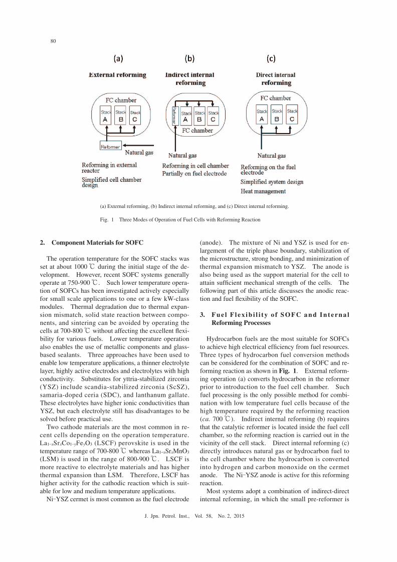
Hydrocarbon fuels are the most suitable for SOFCs to achieve high electrical efficiency from fuel resources. Three types of hydrocarbon fuel conversion methods can be considered for the combination of SOFC and re-forming reaction as shown in Fig. 1. External reform-ing operation (a) converts hydrocarbon in the reformer prior to introduction to the fuel cell chamber. Such fuel processing is the only possible method for combi-nation with low temperature fuel cells because of the high temperature required by the reforming reaction (ca. 700 ℃). Indirect internal reforming (b) requires that the catalytic reformer is located inside the fuel cell chamber, so the reforming reaction is carried out in the vicinity of the cell stack. Direct internal reforming (c) directly introduces natural gas or hydrocarbon fuel to the cell chamber where the hydrocarbon is converted into hydrogen and carbon monoxide on the cermet anode. The Ni_YSZ anode is active for this reforming reaction.
Most systems adopt a combination of indirect-direct internal reforming, in which the small pre-reformer is
80
J. Jpn. Petrol. Inst., Vol. 58, No. 2, 2015
(a) External reforming, (b) Indirect internal reforming, and (c) Direct internal reforming.
Fig. 1● Three Modes of Operation of Fuel Cells with Reforming Reaction

installed in the fuel cell chamber to recover the heat generated by the electrochemical reaction for endo-thermic reforming. In many cases, reforming is com-pleted on the anode surface. Conversion of natural gas to a methane and hydrogen mixture is necessary for the pre-reformer unlike the general reformer for complete hydrogen production (Fig. 2). Ethane and higher hydrocarbons should be completely decomposed by the pre-reformer to avoid carbon deposition in the stack.
The reactions proceed on the fuel electrode is shown in Fig. 2. The steam reforming of methane (1) and the water gas shift reaction (3) are considered. In addition to these reactions, dry reforming (reaction (2)) proceeds as carbon dioxide is formed by the electro-chemical oxidation of CO and the shift reaction. Generally, the Ni catalyst is sufficiently active in the temperature range above 650 ℃. The conversion is further limited by the equilibrium. Since the reform-ing reaction is highly endothermic, the equilibrium con-version increases as the reaction temperature rises up to almost 100 % at 700 ℃ or higher. Hydrocarbon fuels should be supplied with caution to avoid carbon deposi-tion. Carbon deposition occurs either through the cracking reaction (4) at 600-700 ℃ or by the equilibra-tion of disproportionation of CO (Boudouard reaction (5)) below this temperature range. The deposited car-bon covers the Ni surface in the initial stage, and finally results in pore closure and blocking of access of the gaseous reactants to the reaction sites. Adequate steam should be added to the hydrocarbon fuel to pre-
vent carbon deposition. The oxidant CO2 and H2O are also formed by anodic electrochemical oxidation at the triple phase boundary (TPB). Therefore, carbon depo-sition significantly proceeds in the open circuit condition, since no electrochemical formation of water occurs4). The triple phase boundary in the Ni_YSZ system is defined as the boundary between Ni, YSZ, and the gas phases.
Commercial household SOFC units are equipped with a steam reformer for production of hydrogen and carbon monoxide from methane. Exothermic heat is supplied from an SOFC generator unit to the endo-thermic reforming reaction for increased fuel energy. The gains of total and electrochemical energies before and after reforming of methane at 800 ℃ are shown in Fig. 3. The total energy gain with reforming is equal to the endothermic heat supplied from the environment. The maximum electrical energy corresponds to ∆G of the combustion of methane and reformate. The thermal energy is further divided into usable and unusable ener-gies defined as high (800 ℃) and low (25 ℃) tempera-ture heat sources. A large amount of unreformed methane is not directly supplied to the fuel cell unit to avoid rapid progress of the endothermic reaction and the consequent temperature decrease, whereas methane can be partly supplied because of the adequate catalytic activity of Ni-based cermet for the reforming reaction. Even with direct supply of methane, methane is not oxidized directly by the electrochemical reaction. Instead the combination of thermal catalytic reforming and electrochemical oxidation of hydrogen and carbon monoxide proceeds on the Ni surface and triple phase boundary, respectively. If a non-equilibrium gaseous mixture of CH4, H2, CO, H2O, and CO2 is supplied to the SOFC cell, the open circuit voltage is determined by the equilibrium of H2, CO, H2O, and CO2. Methane acts as inert gas for determining the open circuit volt-age.
81
J. Jpn. Petrol. Inst., Vol. 58, No. 2, 2015
Surface reaction on catalystSteam reforming of methane CH4+H2O→ CO+3 H2 (1)Dry reforming CH4+ CO2→2CO+2H2 (2)Water gas shift reaction CO +H2O→ CO2+H2 (3)
Carbon depositionCracking CH4→ C+2 H2 (4)Disproportionation 2 CO→ C+CO2 (5)
Reaction at TPBAnodic reaction● H2+O2–→ H2O+2 e– (6)
CO+O2–→ CO2+2 e– (7)
Fig. 2● Electrochemical and Chemical Reactions in the Vicinity of the Triple Phase Boundary (TPB) of the Fuel Electrode
TE: thermal energy, EE: electrical energy, UE: unusable energy, TE+EE: exergy.
Fig. 3● Ideal Energy Obtained from Methane, Reformed Gas, and Partial Oxidation Reformate at 800 ℃

4. Carbon Deposition
Direct supply of methane is worth investigating not only for simplification of the fuel supply system, but also for clarification of the effect of accidental supply of concentrated methane. Thermal and catalytic cracking of hydrocarbons should be avoided as the re-action results in carbon deposition. The equilibrium region of carbon deposition is shown in the C_H_O dia-gram of Fig. 45). At high temperatures above 800 ℃, the straight line connecting carbon monoxide and hydrogen is the boundary of the carbon deposition region. For the reforming system of mixed methane and water, the steam to carbon ratio (S/C) of unity is the boundary of the carbon deposition region. At lower temperatures, disproportionation of CO and methane formation becomes favorable which corresponds to the bending of the carbon deposition region. However, carbon deposition proceeds even outside this region, especially in the presence of C2 and higher hydrocarbons. Carbon deposition becomes serious with higher carbon number of the fuel because of carbon residue.
The current versus voltage characteristics were mea-sured before and after direct supply of C3H8. The steam to carbon ratio was set outside the deposition re-gion estimated from the thermodynamic characteristics, and the terminal voltage was significantly lowered after generation with C3H8 (Fig. 5). Carbon deposition proceeded on the Ni cermet electrode, especially in the open circuit condition. Direct introduction of higher hydrocarbons has been suggested but at the operating temperatures of SOFCs, hydrocarbon fuels are convert-ed nonselectively to carbonaceous species and solid car-bon by cracking. Both cracking to lower hydrocar-bons and chain growth to carbonaceous deposits occur. Thus, the high activity for reforming is important to avoid nonselective side reactions5)~7). The general
countermeasure to suppress deposition of carbon is to supply excess water. Steam is supplied as part of the feed gas, but the fuel electrode is protected by steam and CO2 formed by the electrochemical reaction.
The ease of carbon deposition on the electrode is de-pendent on the cermet material as well as the S/C ratio. Therefore, another approach to avoid carbon deposition is to design catalysts which are less active for carbon formation8),9). The fuel electrode catalyst should be designed to achieve high electrocatalytic activity in ad-dition to reforming activity and suppression of carbon deposition. The deposition rate is significantly affected by the types of metal and oxide in the cermet material as demonstrated by the gravimetric measurement of de-posited carbon in Fig. 6. Metallic nickel demonstrated high activity for carbon deposition, whereas Ru-cermet resulted in hardly observable carbon deposition. Based on the gravimetric analysis, the relative deposi-tion rates of carbon for Ni- and Ru-based cermet were;
82
J. Jpn. Petrol. Inst., Vol. 58, No. 2, 2015
Fig. 4● Equilibrium Carbon Deposition Region in the C_H_O Diagram
Fig. 5● I-V Characteristics for a Ni_YSZ Anode Cell with H2 Supply Bubbled at 0 ℃ before and after Generation with C3H8 (S/C=3.0)
Fig. 6● Gravimetric Measurement of Carbon Deposition on Various Ni- and Ru-cermets Using CH4 (S/C=0.0027) at 1000 ℃

Ru_YSZ<Ni_ScSZ<Ni_YSZ<Ni_SDC (samaria-doped ceria),The low deposition rate for the Ru-based cermet was attributed to the lower solubility of carbon in the metallic bulk than for the Ni-based cermet. Ru is more active for the steam reforming of hydrocarbon than nickel, but the high cost of this compound is a drawback to practical application. Fabrication of cermet with good contact with the electrolyte is also difficult due to evaporation of oxide in an oxidizing atmosphere and poor sinter-ability in a reducing atmosphere.
Copper has been proposed as a cermet component to avoid carbon deposition10). However, copper metal undergoes rapid sintering at 700 ℃ or higher. The small amount of carbon deposition for Ni_ScSZ may result from its high ionic conductivity. SDC possesses only poor ionic conductivity under severe reducing con-ditions of carbon deposition. However, Ni demon-strated high activity for gasification of deposited carbon. Some less active oxide anodes have been proposed. However, cracking of hydrocarbon at elevated tempera-tures should be considered.
The deposited carbon was characterized by micro-Raman spectroscopy as shown in Fig. 7. Two types of deposited carbon were observed, graphitic carbon deposited on the surface of the Ni metal at the initial stage of deposition, and a large amount of amorphous carbon deposited on the outer surface and in the pores of the fuel electrode layer11). Amorphous and graphitic carbons were observed at 1350 cm–1 and 1585 cm–1,
which are expressed as the D- and G-band, respectively. The fuel mixture with S/C≈1 led to slow deposition of graphitic carbon. The production of oxidants, CO2 and H2O, with electrochemical oxidation of fuel re-stricted carbon deposition because of the enhanced oxy-gen potential in the vicinity of TPB. In contrast, low S/C at the open circuit condition led to rapid deposition of amorphous carbon. The graphitic carbon deposited on the surface could be easily removed by H2, H2O or anodic oxidation current due to gasification. The large amount of amorphous carbon formed in the bulk Ni_
YSZ cermet resulted in fatal and irreversible degrada-tion of the cell.
One of the most important applications of SOFC sys-tems is combination with coal gasification. Gasified coal gas is cleaned and supplied to the SOFC genera-tion unit. Then the outlet gas with high thermal energy is introduced to a gas turbine generator. For this pur-pose, the degradation of the cells and stacks caused by the various contaminants in gasified fuel must be clari-fied. A number of contaminants such as sulfur, chlo-rine, COS, ammonia, and heavy metals can be expected even after cleaning of coal gas. For wider application of SOFC systems, other fuels such as liquid fuels, bio-fuels, dimethyl ether, or organic compounds in waste should be investigated.
5. Deterioration with Steam
Dilution of fuel with water is effective to avoid car-bon deposition during the internal reforming process as well as in the reformate fuel supply. However, highly concentrated steam often leads to extremely high water content in the downstream region of the fuel cell after discharge of the cell because of the additional evolution of water by the electrochemical oxidation of hydrogen. Such extremely high water content deteriorates the active Ni surface and catalytic activity due to the strong adsorption of water12). The degradation of the anode proceeds under the discharge condition at low terminal voltage using fuel diluted with a large amount of steam. As shown in Fig. 8, the terminal voltage was stable at current density of 100 mA cm–2 even with high steam content, whereas gradual degradation was followed by a sharp drop of the terminal voltage at 200 mA cm–2. The amount of formed water was doubled by increasing the current from 100 to 200 mA cm–2. The deteriora-tion with water was reversible in the initial stage at high terminal voltage, which was observable as a gradual degradation in terminal voltage. The high overvoltage became irreversible accompanied by a sharp drop in the subsequent degradation stage. High local water con-tent in the vicinity of TPB facilitates strong adsorption on Ni.
Such degradation with steam is characterized by a large increase in ohmic resistance. Further deteriora-
83
J. Jpn. Petrol. Inst., Vol. 58, No. 2, 2015
The numbers in the figure denote the spectra taken from different depths from the surface (5) to electrolyte interface (1) in the fuel elec-trode.
Fig. 7● Raman Spectra of Ni_YSZ after Discharge at 0.80 V for 34 h with a Supply of Humidified CH4 (S/C=0.8)
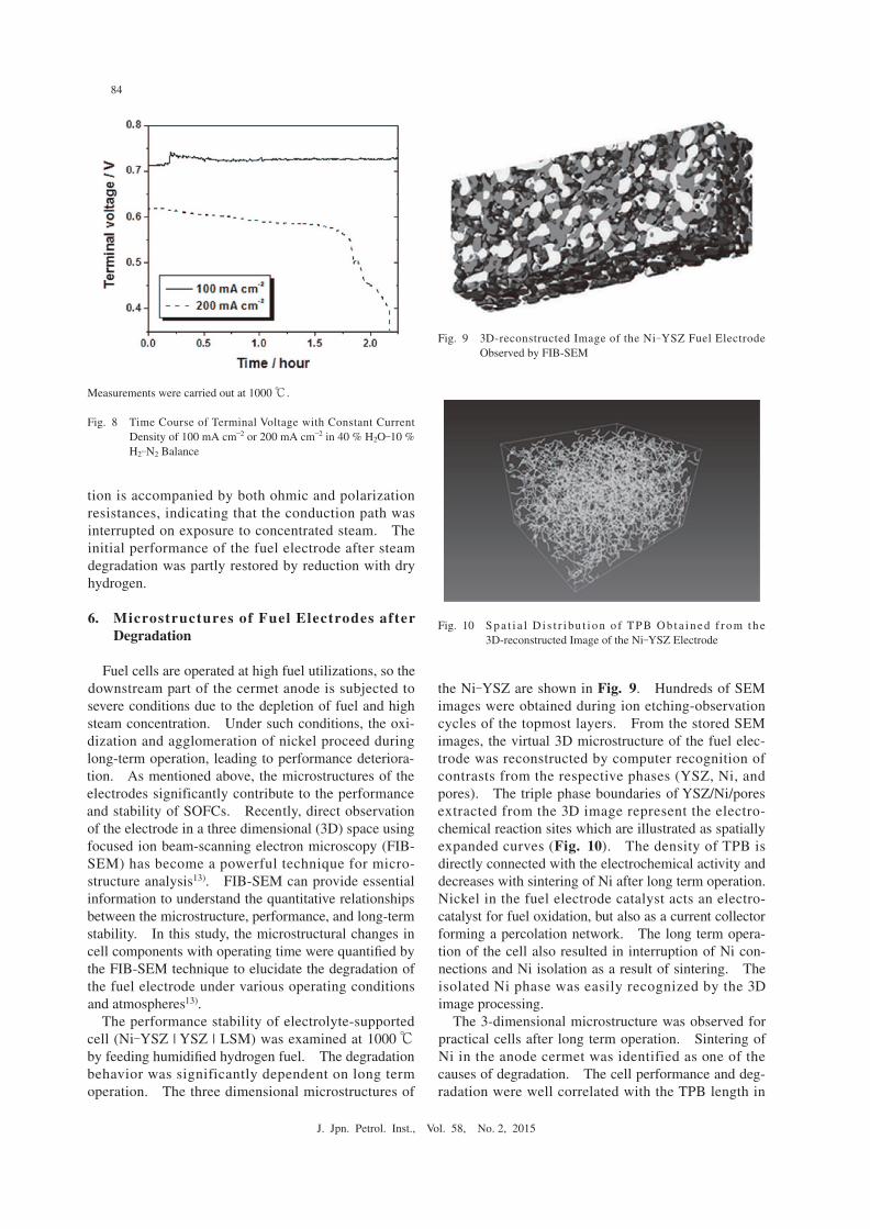
tion is accompanied by both ohmic and polarization resistances, indicating that the conduction path was interrupted on exposure to concentrated steam. The initial performance of the fuel electrode after steam degradation was partly restored by reduction with dry hydrogen.
6. Microstructures of Fuel Electrodes after Degradation
Fuel cells are operated at high fuel utilizations, so the downstream part of the cermet anode is subjected to severe conditions due to the depletion of fuel and high steam concentration. Under such conditions, the oxi-dization and agglomeration of nickel proceed during long-term operation, leading to performance deteriora-tion. As mentioned above, the microstructures of the electrodes significantly contribute to the performance and stability of SOFCs. Recently, direct observation of the electrode in a three dimensional (3D) space using focused ion beam-scanning electron microscopy (FIB-SEM) has become a powerful technique for micro-structure analysis13). FIB-SEM can provide essential information to understand the quantitative relationships between the microstructure, performance, and long-term stability. In this study, the microstructural changes in cell components with operating time were quantified by the FIB-SEM technique to elucidate the degradation of the fuel electrode under various operating conditions and atmospheres13).
The performance stability of electrolyte-supported cell (Ni_YSZ | YSZ | LSM) was examined at 1000 ℃ by feeding humidified hydrogen fuel. The degradation behavior was significantly dependent on long term operation. The three dimensional microstructures of
the Ni_YSZ are shown in Fig. 9. Hundreds of SEM images were obtained during ion etching-observation cycles of the topmost layers. From the stored SEM images, the virtual 3D microstructure of the fuel elec-trode was reconstructed by computer recognition of contrasts from the respective phases (YSZ, Ni, and pores). The triple phase boundaries of YSZ/Ni/pores extracted from the 3D image represent the electro-chemical reaction sites which are illustrated as spatially expanded curves (Fig. 10). The density of TPB is directly connected with the electrochemical activity and decreases with sintering of Ni after long term operation. Nickel in the fuel electrode catalyst acts an electro-catalyst for fuel oxidation, but also as a current collector forming a percolation network. The long term opera-tion of the cell also resulted in interruption of Ni con-nections and Ni isolation as a result of sintering. The isolated Ni phase was easily recognized by the 3D image processing.
The 3-dimensional microstructure was observed for practical cells after long term operation. Sintering of Ni in the anode cermet was identified as one of the causes of degradation. The cell performance and deg-radation were well correlated with the TPB length in
84
J. Jpn. Petrol. Inst., Vol. 58, No. 2, 2015
Measurements were carried out at 1000 ℃.
Fig. 8● Time Course of Terminal Voltage with Constant Current Density of 100 mA cm–2 or 200 mA cm–2 in 40 % H2O_10 % H2
_N2 Balance
Fig. 9● 3D-reconstructed Image of the Ni_YSZ Fuel Electrode Observed by FIB-SEM
Fig. 10● S p a t i a l D i s t r i bu t i o n o f T P B O b t a i n e d f r o m t h e 3D-reconstructed Image of the Ni_YSZ Electrode
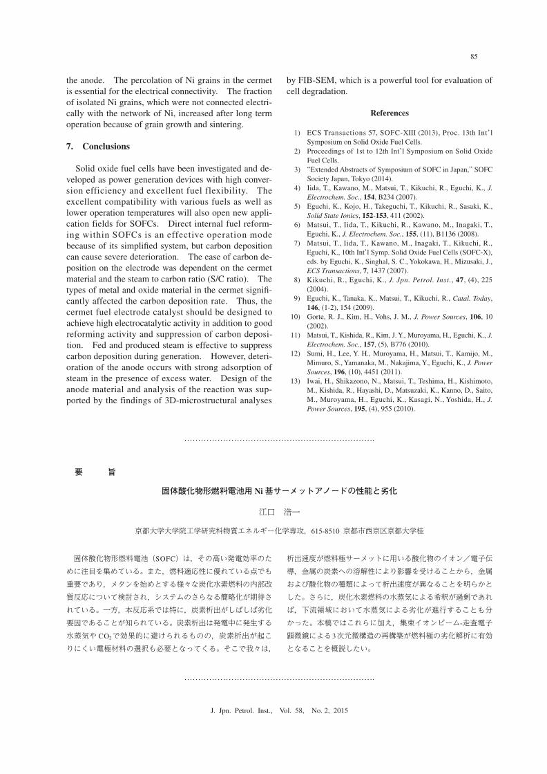
the anode. The percolation of Ni grains in the cermet is essential for the electrical connectivity. The fraction of isolated Ni grains, which were not connected electri-cally with the network of Ni, increased after long term operation because of grain growth and sintering.
7. Conclusions
Solid oxide fuel cells have been investigated and de-veloped as power generation devices with high conver-sion efficiency and excellent fuel flexibility. The excellent compatibility with various fuels as well as lower operation temperatures will also open new appli-cation fields for SOFCs. Direct internal fuel reform-ing within SOFCs is an effective operation mode because of its simplified system, but carbon deposition can cause severe deterioration. The ease of carbon de-position on the electrode was dependent on the cermet material and the steam to carbon ratio (S/C ratio). The types of metal and oxide material in the cermet signifi-cantly affected the carbon deposition rate. Thus, the cermet fuel electrode catalyst should be designed to achieve high electrocatalytic activity in addition to good reforming activity and suppression of carbon deposi-tion. Fed and produced steam is effective to suppress carbon deposition during generation. However, deteri-oration of the anode occurs with strong adsorption of steam in the presence of excess water. Design of the anode material and analysis of the reaction was sup-ported by the findings of 3D-microstructural analyses
by FIB-SEM, which is a powerful tool for evaluation of cell degradation.
References
1) ECS Transactions 57, SOFC-XIII (2013), Proc. 13th Int’l Symposium on Solid Oxide Fuel Cells.
2) Proceedings of 1st to 12th Int’l Symposium on Solid Oxide Fuel Cells.
3) “Extended Abstracts of Symposium of SOFC in Japan,” SOFC Society Japan, Tokyo (2014).
4) Iida, T., Kawano, M., Matsui, T., Kikuchi, R., Eguchi, K., J. Electrochem. Soc., 154, B234 (2007).
5) Eguchi, K., Kojo, H., Takeguchi, T., Kikuchi, R., Sasaki, K., Solid State Ionics, 152-153, 411 (2002).
6) Matsui, T., Iida, T., Kikuchi, R., Kawano, M., Inagaki, T., Eguchi, K., J. Electrochem. Soc., 155, (11), B1136 (2008).
7) Matsui, T., Iida, T., Kawano, M., Inagaki, T., Kikuchi, R., Eguchi, K., 10th Int’l Symp. Solid Oxide Fuel Cells (SOFC-X), eds. by Eguchi, K., Singhal, S. C., Yokokawa, H., Mizusaki, J., ECS Transactions, 7, 1437 (2007).
8) Kikuchi, R., Eguchi, K., J. Jpn. Petrol. Inst., 47, (4), 225 (2004).
9) Eguchi, K., Tanaka, K., Matsui, T., Kikuchi, R., Catal. Today, 146, (1-2), 154 (2009).
10) Gorte, R. J., Kim, H., Vohs, J. M., J. Power Sources, 106, 10 (2002).
11) Matsui, T., Kishida, R., Kim, J. Y., Muroyama, H., Eguchi, K., J. Electrochem. Soc., 157, (5), B776 (2010).
12) Sumi, H., Lee, Y. H., Muroyama, H., Matsui, T., Kamijo, M., Mimuro, S., Yamanaka, M., Nakajima, Y., Eguchi, K., J. Power Sources, 196, (10), 4451 (2011).
13) Iwai, H., Shikazono, N., Matsui, T., Teshima, H., Kishimoto, M., Kishida, R., Hayashi, D., Matsuzaki, K., Kanno, D., Saito, M., Muroyama, H., Eguchi, K., Kasagi, N., Yoshida, H., J. Power Sources, 195, (4), 955 (2010).
85
J. Jpn. Petrol. Inst., Vol. 58, No. 2, 2015
要 旨
固体酸化物形燃料電池用 Ni基サーメットアノードの性能と劣化
江口 浩一
京都大学大学院工学研究科物質エネルギー化学専攻,615-8510 京都市西京区京都大学桂
固体酸化物形燃料電池(SOFC)は,その高い発電効率のために注目を集めている。また,燃料適応性に優れている点でも重要であり,メタンを始めとする様々な炭化水素燃料の内部改質反応について検討され,システムのさらなる簡略化が期待されている。一方,本反応系では特に,炭素析出がしばしば劣化要因であることが知られている。炭素析出は発電中に発生する水蒸気や CO2で効果的に避けられるものの,炭素析出が起こりにくい電極材料の選択も必要となってくる。そこで我々は,
析出速度が燃料極サーメットに用いる酸化物のイオン/電子伝導,金属の炭素への溶解性により影響を受けることから,金属および酸化物の種類によって析出速度が異なることを明らかとした。さらに,炭化水素燃料の水蒸気による希釈が過剰であれば,下流領域において水蒸気による劣化が進行することも分かった。本稿ではこれらに加え,集束イオンビーム-走査電子顕微鏡による3次元微構造の再構築が燃料極の劣化解析に有効となることを概説したい。


![Preparation of La0.6Ba0.4Co0.2Fe0.8O3 (LBCF) Nanoceramic ...and Ni-YSZ cermet (Anode) [3,4]. Among the cathode materials reported (La, Sr) MnO3 (LSM) based perov- skite, due to their](https://img.pdfslide.us/doc/110x75/5e72394adfce751f962b81f4/preparation-of-la06ba04co02fe08o3-lbcf-nanoceramic-and-ni-ysz-cermet-anode.jpg)