Embed Size (px)
Citation preview
Electrochimica Acta 202 (2016) 216–223
Performance and Degradation of A Lithium-Bromine Rechargeable FuelCell Using Highly Concentrated Catholytes
Peng Baia,1,*, Martin Z. Bazanta,b,c,1
aDepartment of Chemical Engineering, Massachusetts Institute of Technology, Cambridge, MA 02139, USAbDepartment of Mathematics, Massachusetts Institute of Technology, Cambridge, MA 02139, USAcDepartment of Materials Science and Engineering and SUNCAT Interfacial Science and Catalysis, Stanford University, Stanford, CA 94305, USA
A R T I C L E I N F O
Article history:Received 5 January 2016Received in revised form 22 March 2016Accepted 3 April 2016Available online 4 April 2016
Keywords:high specific energysolid-state electrolyteslithium-air batteriesflow batterieselectric vehicles
A B S T R A C T
Lithium-air batteries have been considered as ultimate solutions for the power source of long-rangeelectrified transportation, but state-of-the-art prototypes still suffer from short cycle life, low efficiencyand poor power output. Here, a lithium-bromine rechargeable fuel cell using highly concentratedbromine catholytes is demonstrated with comparable specific energy, improved power density, andhigher efficiency. The cell is similar in structure to a hybrid-electrolyte Li-air battery, where a lithiummetal anode in nonaqueous electrolyte is separated from aqueous bromine catholytes by a lithium-ionconducting ceramic plate. The cell with a flat graphite electrode can discharge at a peak power densityaround 9 mW cm�2 and in principle could provide a specific energy of 791.8 Wh kg�1, superior to mostexisting cathode materials and catholytes. It can also run in the regenerative mode to recover the lithiummetal anode and free bromine with 80-90% voltage efficiency, without any catalysts. Degradation of thesolid electrolyte and the evaporation of bromine during deep charging are challenges that should beaddressed in improved designs to fully exploit the high specific energy of the liquid bromine. Theproposed system offers a potential power source for long-range electric vehicles, beyond current Li-ionbatteries yet close to envisioned Li-air batteries.
ã 2016 Elsevier Ltd. All rights reserved.
Contents lists available at ScienceDirect
Electrochimica Acta
journal homepa ge: www.elsev ier .com/locate /e lectacta
1. Introduction
Li-ion batteries have powered the revolution in portableelectronics and tools for decades, but their initial penetrationinto the market for electrified transportation has so far onlyachieved products that are very expensive or short in driving range[1]. Lithium-air batteries are considered among the most promis-ing technologies beyond Li-ion batteries [2–4], since the very hightheoretical specific energy may reduce the unit cost down to lessthan US$150 per kWh, while increase the driving range of anelectric vehicle to more than 550 km [5]. However, just as that Li-ion technology experienced many problems at its advent decadesago, Li-air technology is currently facing several challenges [6]. Fornonaqueous Li-air batteries composed of lithium metal, organicelectrolyte and porous air electrode, a robust electrolyte resistantto the attack by the reduced O2
� species is yet to be developed toenable highly reversible cycling [4,5]. For aqueous and hybrid Li-airbatteries that adopt solid-state electrolytes to protect the
* Corresponding author.E-mail address: [email protected] (P. Bai).
1 ISE Member.
http://dx.doi.org/10.1016/j.electacta.2016.04.0100013-4686/ã 2016 Elsevier Ltd. All rights reserved.
nonaqueous electrolyte and lithium metal anode from contami-nation, it is still quite challenging to improve the poor kinetics ofthe oxygen reduction reaction (ORR) and the oxygen evolutionreaction (OER) simultaneously [7] and economically [4]. Tocircumvent this challenge, Goodenough et al. [8–10] and Zhouet al. [11] independently extended the hybrid Li-air battery tohybrid Li-redox flow batteries by flowing through liquid catholytesinstead of air [12,13]. The key concept of flowing electrodes is alsoexploited in semi-solid flow batteries [14], redox flow li-ionbatteries [15,16], and flowable supercapacitors [17].
One of the most attractive features of flow batteries is thedecoupling of power and energy, which enables more flexiblesystem customization, either by increasing the number ofelectrode pairs for higher power output, or by increasing the sizeof the tank and concentration of electrolytes to store more energy[13]. For electric vehicles with limited on-board space to storeelectrolytes, high solubility of the active species becomesespecially important. Recognizing that iodine has an extremelyhigh solubility in iodide solutions, Byon et al. investigated theperformance of dilute iodine/iodide catholyte in hybrid-electrolytelithium batteries both in the static mode [18] and the flow-throughmode [19], in which the end-of-discharge product is LiI.Concentrated iodine/iodide solution was also employed in a recent
Lith
ium
Org
anic
ele
ctro
lyte
Fully DischargedCatholyte
11 M LiBr
Pure Br2
Br2 + LiBr
Pump
Fully ChargedCatholyte
LATP
Gra
phite
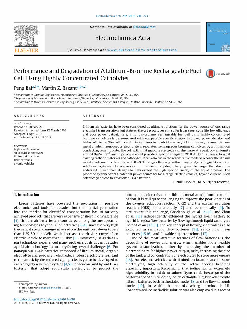
Fig. 1. Schematic illustration of the Li-Br fuel cell.
P. Bai, M.Z. Bazant / Electrochimica Acta 202 (2016) 216–223 217
zinc-polyiodide flow battery, producing ZnI2 at the end ofdischarge [20]. Comparing these two reports, although LiI andZnI2 solutions have similar capacity at their solubility limits, theuse of a lithium anode increases the voltage almost three-fold, thusproviding much higher specific energy. Table 1 summaries thetheoretical specific energies of catholytes used in several state-of-the-art flow or static-liquid batteries, where LiBr solution emergesas the best candidate, having almost twice the specific energy ofthe aqueous Li-air battery using alkaline catholyte (LiOH).
This extraordinary property has started to attract the attentionof researchers to develop various Li-Br batteries. Such systemsalways involve a liquid-solid-liquid hybrid electrolyte, in order toaccommodate the nonaqueous and aqueous electrolytes. Duringdischarge, lithium metal in the nonaqueous electrolyte is oxidizedinto lithium ions (Li!Li++e�), which migrate toward the cathode,while electrons travel through the external circuit to reach thecathode. At the surface of cathode, bromine is reduced by theincoming electrons to bromide ions (Br2+2e�!2Br�), followed byfast complexation with bromine to form more stable tribromideions (Br�+Br2$Br3�). The reactions are reversed during recharg-ing. Zhao et al. fabricated a static Li-Br battery with a solution of1 M KBr and 0.3 M LiBr, which was charged to 4.35 V thendischarged at various electrochemical conditions [23]. Themaximum power it could deliver within the safety window was1000 W kg�1, equivalent to 5.5 mW cm�2 if calculated with theirloading density of LiBr (5.5 mg cm�2). Chang et al. paired aprotected lithium metal anode [26] with a small glassy carbonelectrode (3 mm diameter) to test the performance of 0.1 M Br2 in1 M LiBr and 1 M Br2 in 7 M LiBr solutions, respectively. The latterprovided a peak power density of 29.67 mW cm�2 at �2.5 V [27]. Inthe development of a better Li-Br battery, Takemoto and Yamadafound that degradation of the solid electrolyte ceramic plate is themajor source of deterioration of the cell performance. Their carefulanalyses on samples soaked in dilute bromine/bromide solutionsfor 3 days suggested the development of a Li-ion depletion layer inthe solid electrolyte plate [28].
Given the strongly fuming and oxidative nature of bromine, it isunderstandable that previous work has only considered diluteelectrolytes. Indeed, the high vapor pressure of bromine that buildsup in a closed static liquid cell can easily rupture the ceramicseparator. Such problems can be avoided in a flow cell, but apractical way of utilizing the high specific energy of lithium-bromine chemistry has yet to be proposed and demonstrated,using highly concentrated bromine/bromide catholytes.
In this paper, we design and fabricate a lithium-bromine fuelcell; explore the feasibility of using highly concentrated brominecatholytes of six different compositions of LiBr and Br2, represent-ing different states of charge (SOC) associated with 11 M LiBrsolution by conservation of elemental bromine; and examine thedegradation of the rate-limiting component, the lithium ionconducting solid electrolyte, by scanning electron microscopy andelectrochemical impedance spectroscopy. Our results suggest that
Table 1Comparison of the specific energies of various fully discharged catholytes at their solu
Discharge product Solubility [21,22][g per 100 ml of water]
Molality[mol per kg of water]
LiBr 164.00 18.89
LiI 165.00 12.33
LiOH 12.40 5.18
ZnBr2 447.00 19.85
ZnI2 332.00 10.40
FeCl2 62.50 4.93
K4Fe(CN)6�3H2O 28.00 0.66
Li2Sn – –
a properly designed rechargeable Li-Br fuel cell system has thepotential to power long-range electric vehicles.
2. Experimental Section
2.1. Fuel Cell Design and Fabrication
The structure of the fuel cell is schematically shown in Fig. 1,which is similar to the hybrid aqueous Li-air battery [29], wherelithium metal in nonaqueous electrolyte is separated from aqueouscatholytes by a solid electrolyte (Li2O-Al2O3-SiO2-TiO2-GeO2-P2O5,LATP, 10�4 S cm�1, 25.4-mm square by 150-mm thick, Ohara Inc.Japan). A catalyst-free flat graphite plate is used as cathode.Catholytes flow through the cathode channel to complete theliquid-solid-liquid ionic pathway between lithium metal anodeand graphite cathode. Details of the materials, design andfabrication of the fuel cell can be found elsewhere [30].
2.2. Catholytes Preparation
Theoretically, the fully discharged catholyte should not containany Br2 for further reduction reaction. It therefore must be pureLiBr solution. To avoid unexpected precipitation due to tempera-ture fluctuations, we chose not to use the saturated LiBr solution(close to12 M), but the slightly more dilute option, 11 M LiBraqueous solution, as the end-of-discharge catholyte. And accordingto the conservation of elemental bromine, we prepared 1 M Br2 in9 M LiBr (1 M/9 M), 2 M/7 M, 3 M/5 M, 4 M/3 M and 5 M/1 Msolutions as the intermediate catholytes. Note that only 5 M/1 Msolution has precipitated liquid Br2 at the bottom of the solution,since the saturated concentration of Br2 in 1 M LiBr solution is
bility limits.
Specific capacity[Ah per kg of solution]
OCV[V]
Specific energy[Wh per kg of solution]
191.72 4.13 [23] 791.82124.68 3.57 [18] 445.12123.45 3.4 [2] 419.73194.51 1.85 [24] 359.84129.06 1.30 [20] 167.7781.33 4.06 [11] 330.1913.88 3.99 [10] 55.38
– – 170 [25]
0123456789
Pow
er d
ensi
ty /
mW
cm
-2
0.5
1
1.5
2
2.5
3
3.5
4
4.5
Volta
ge /
V
0 1 2 3 4 5 6Current density / mA cm-2
c
5M/1M4M/3M3M/5M2M/7M1M/9M
0 100 200 3001
1.5
2
2.5
3
3.5
4
Time / s
Volta
ge /
V
a
b
0.50 mA cm-2
1.00 mA cm-2
1.50 mA cm-2
2.00 mA cm-2
2.50 mA cm-2
3.00 mA cm-2
3.50 mA cm-2
4.00 mA cm-2
4.50 mA cm-2
5.00 mA cm-2
5.50 mA cm-2
6.00 mA cm-2
0 1 2 3 4 5 6Current density / mA cm-2
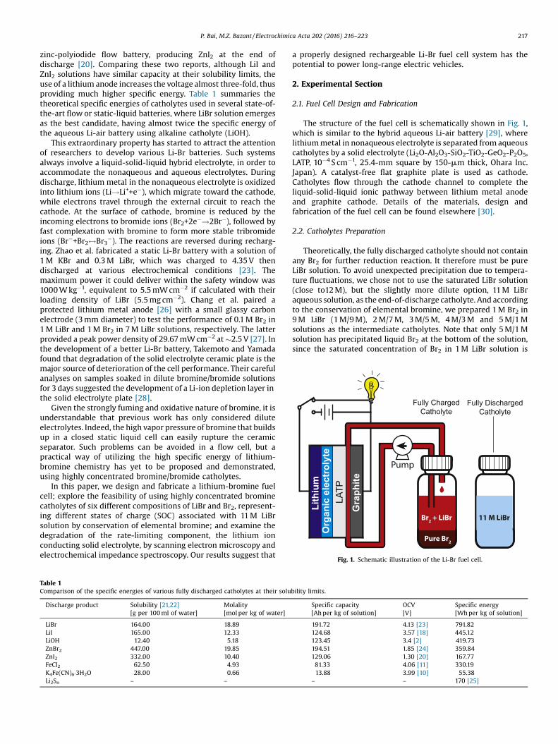
Fig. 2. (a) 5-min Galvanostatic discharging with 1 M/9 M catholytes. (b) Polariza-tion curves of the averaged voltages versus the applied current densities and (c) thecorresponding power output for the proposed catholytes. Note that the saturatedconcentration of Br2 in 1 M LiBr is around 2.2 M, which is the actual catholytepassing through the cell, no liquid Br2 was directly introduced into the cell.
218 P. Bai, M.Z. Bazant / Electrochimica Acta 202 (2016) 216–223
around 2.2 M (1.93 g Br2 in 10 ml LiBr solution). Only thesupernatant solution, i.e. �2.2 M/1 M, was used in the tests, butwe nonetheless keep the notation of 5 M/1 M for easier under-standing of its relation with other catholytes.
2.3. Electrochemical Measurements
Polarization curves were obtained by an Arbin battery tester(BT-2043, Arbin Instruments) at the flow rate of 1 ml min�1 cm�2.Every data point came from the averaged voltage of five-minutecharge or discharge. Before testing a different catholyte, DI waterand air were pumped to flush the tubing and cell at 5 ml min�1
cm�2 for 30 mins and 10 minutes, respectively. Potentiostatic EISexperiments of the Pt|LATP|Pt dry cells were conducted withGamry Reference 3000, with a 5 mV excitation from 0.1 Hz to1 MHz.
3. Results
3.1. Electrochemical Performance
The polarization curves shown in Fig. 2 reveal the linearrelationship between the response voltages and the appliedcurrent densities. A peak power density of 8.5 mW cm�2 at 1.8 Vcan be obtained with 1 M Br2 in 9 M LiBr (1 M/9 M) solution, whichis consistent with the recent reports of both the static [23] and flow[30] Li-Br cells using dilute bromine catholytes. The fact thatincreasing the concentration of Br2 here does not improve thedischarge performance further confirms that the rate-limitingprocess is not the transport in the liquid catholyte, but theconduction of lithium ions through the ceramic solid electrolyte.Data in Fig. 2 also reveal that the slope of the polarization curvesbecomes increasingly steeper and power density smaller over time.This is due to the cumulative corrosion of the LATP plate, consistentwith the sequence of experiments from low Br2 concentration tohigh Br2 concentration.
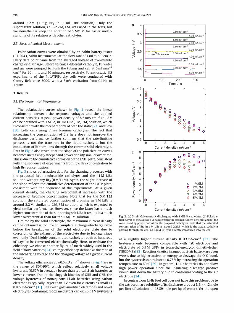
Fig. 3 shows polarization data for the charging processes withthe proposed bromine/bromide catholytes and the 11 M LiBrsolution without any Br2 (0 M/11 M). Again, the slight increase ofthe slope reflects the cumulative deterioration of the LATP plate,consistent with the sequence of the experiments. At a givencurrent density, the charging overpotential increases with theincrease of bromine concentration. Note that for the 5 M/1 Msolution, the saturated concentration of bromine in 1 M LiBr isaround 2.2 M, similar to 2 M/7 M solution, which is expected toyield similar performance. However, since the latter has a muchhigher concentration of the supporting salt LiBr, it results in a muchlower overpotential than for the 5 M/1 M solution.
Limited by the solid electrolyte, the maximum current densitycan be obtained is too low to complete a charge-discharge cyclebefore the breakdown of the solid electrolyte plate due tocorrosion, or the exhaust of the electrolyte due to leakage, sinceeven only 10 ml highly concentrated catholyte requires hundredsof days to be converted electrochemically. Here, to evaluate theefficiency, we choose another figure of merit widely used in thefield of flow batteries [24], voltage efficiency, defined as the ratio ofthe discharging voltage and the charging voltage at a given currentdensity.
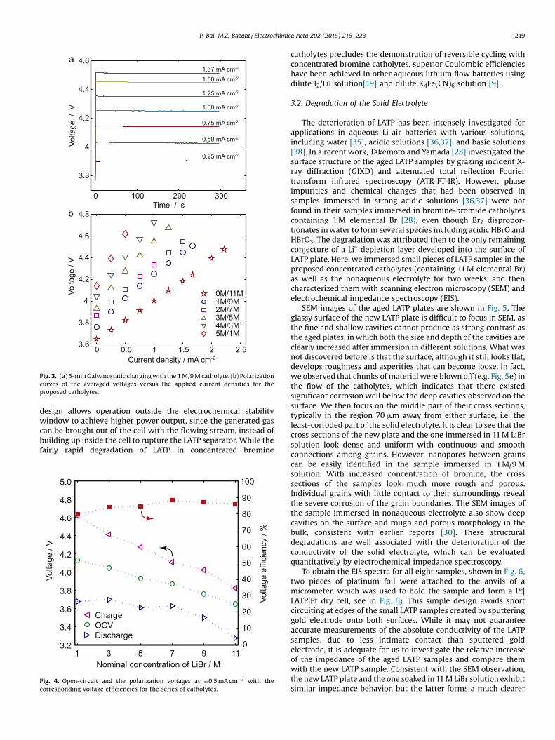
The voltage efficiencies at �0.5 mA cm�2 shown in Fig. 4 are inthe range of 80%-90%, which reflect relatively small voltagehysteresis (0.67 V in average), better than typical Li-air batteries atlower currents. Due to the sluggish kinetics of ORR and OER, thevoltage hysteresis of nonaqueous Li-air batteries using carbonelectrode is typically larger than 1 V even for currents as small as0.105 mA cm�2 [31]. Cells with gold-modified electrodes and novelelectrolytes containing redox mediators can exhibit 1 V hysteresis
at a slightly higher current density 0.313 mA cm�2 [32]. Thehysteresis only becomes comparable with TiC electrode andelectrolyte of 0.5 M LiPF6 in tetraethyleneglycol dimethylether(TEGDME) [33]. Reaction kinetics in aqueous Li-air battery are evenworse, due to higher activation energy to cleavage the O-O bond,but the hysteresis can reduce to 0.75 V by increasing the operationtemperature to 60 �C [29]. In general, Li-air batteries do not allowhigh power operation since the insulating discharge productwould shut down the battery due to conformal coating to the airelectrode [34].
In contrast, our Li-Br fuel cell does not have this problem due tothe extraordinary solubility of its discharge product LiBr (�12 moleper liter of solution, or 18.89 mole per kg of water). Yet the open
0 0.5 1 1.5 2 2.53.6
3.8
4
4.2
4.4
4.6
4.8
Current density / mA cm-2
Volta
ge /
V
0M/11M1M/9M2M/7M3M/5M4M/3M5M/1M
1.67 mA cm-2
1.50 mA cm-2
1.25 mA cm-2
1.00 mA cm-2
0.75 mA cm-2
0.50 mA cm-2
0.25 mA cm-2
a
b
0 100 200 300
3.8
4
4.2
4.4
4.6
Time / s
Volta
ge /
V
Fig. 3. (a) 5-min Galvanostatic charging with the 1 M/9 M catholyte. (b) Polarizationcurves of the averaged voltages versus the applied current densities for theproposed catholytes.
P. Bai, M.Z. Bazant / Electrochimica Acta 202 (2016) 216–223 219
design allows operation outside the electrochemical stabilitywindow to achieve higher power output, since the generated gascan be brought out of the cell with the flowing stream, instead ofbuilding up inside the cell to rupture the LATP separator. While thefairly rapid degradation of LATP in concentrated bromine
0
10
20
30
40
50
60
70
80
90
100
Volta
ge e
ffici
ency
/ %
Volta
ge /
V
Nominal concentration of LiBr / M
ChargeOCVDischarge
3.2
3.4
3.6
3.8
4.0
4.2
4.4
4.6
4.8
5.0
1 3 5 7 9 11
Fig. 4. Open-circuit and the polarization voltages at �0.5 mA cm�2 with thecorresponding voltage efficiencies for the series of catholytes.
catholytes precludes the demonstration of reversible cycling withconcentrated bromine catholytes, superior Coulombic efficiencieshave been achieved in other aqueous lithium flow batteries usingdilute I2/LiI solution[19] and dilute K4Fe(CN)6 solution [9].
3.2. Degradation of the Solid Electrolyte
The deterioration of LATP has been intensely investigated forapplications in aqueous Li-air batteries with various solutions,including water [35], acidic solutions [36,37], and basic solutions[38]. In a recent work, Takemoto and Yamada [28] investigated thesurface structure of the aged LATP samples by grazing incident X-ray diffraction (GIXD) and attenuated total reflection Fouriertransform infrared spectroscopy (ATR-FT-IR). However, phaseimpurities and chemical changes that had been observed insamples immersed in strong acidic solutions [36,37] were notfound in their samples immersed in bromine-bromide catholytescontaining 1 M elemental Br [28], even though Br2 dispropor-tionates in water to form several species including acidic HBrO andHBrO3. The degradation was attributed then to the only remainingconjecture of a Li+-depletion layer developed into the surface ofLATP plate. Here, we immersed small pieces of LATP samples in theproposed concentrated catholytes (containing 11 M elemental Br)as well as the nonaqueous electrolyte for two weeks, and thencharacterized them with scanning electron microscopy (SEM) andelectrochemical impedance spectroscopy (EIS).
SEM images of the aged LATP plates are shown in Fig. 5. Theglassy surface of the new LATP plate is difficult to focus in SEM, asthe fine and shallow cavities cannot produce as strong contrast asthe aged plates, in which both the size and depth of the cavities areclearly increased after immersion in different solutions. What wasnot discovered before is that the surface, although it still looks flat,develops roughness and asperities that can become loose. In fact,we observed that chunks of material were blown off (e.g. Fig. 5e) inthe flow of the catholytes, which indicates that there existedsignificant corrosion well below the deep cavities observed on thesurface. We then focus on the middle part of their cross sections,typically in the region 70 mm away from either surface, i.e. theleast-corroded part of the solid electrolyte. It is clear to see that thecross sections of the new plate and the one immersed in 11 M LiBrsolution look dense and uniform with continuous and smoothconnections among grains. However, nanopores between grainscan be easily identified in the sample immersed in 1 M/9 Msolution. With increased concentration of bromine, the crosssections of the samples look much more rough and porous.Individual grains with little contact to their surroundings revealthe severe corrosion of the grain boundaries. The SEM images ofthe sample immersed in nonaqueous electrolyte also show deepcavities on the surface and rough and porous morphology in thebulk, consistent with earlier reports [30]. These structuraldegradations are well associated with the deterioration of theconductivity of the solid electrolyte, which can be evaluatedquantitatively by electrochemical impedance spectroscopy.
To obtain the EIS spectra for all eight samples, shown in Fig. 6,two pieces of platinum foil were attached to the anvils of amicrometer, which was used to hold the sample and form a Pt|LATP|Pt dry cell, see in Fig. 6j. This simple design avoids shortcircuiting at edges of the small LATP samples created by sputteringgold electrode onto both surfaces. While it may not guaranteeaccurate measurements of the absolute conductivity of the LATPsamples, due to less intimate contact than sputtered goldelectrode, it is adequate for us to investigate the relative increaseof the impedance of the aged LATP samples and compare themwith the new LATP sample. Consistent with the SEM observation,the new LATP plate and the one soaked in 11 M LiBr solution exhibitsimilar impedance behavior, but the latter forms a much clearer
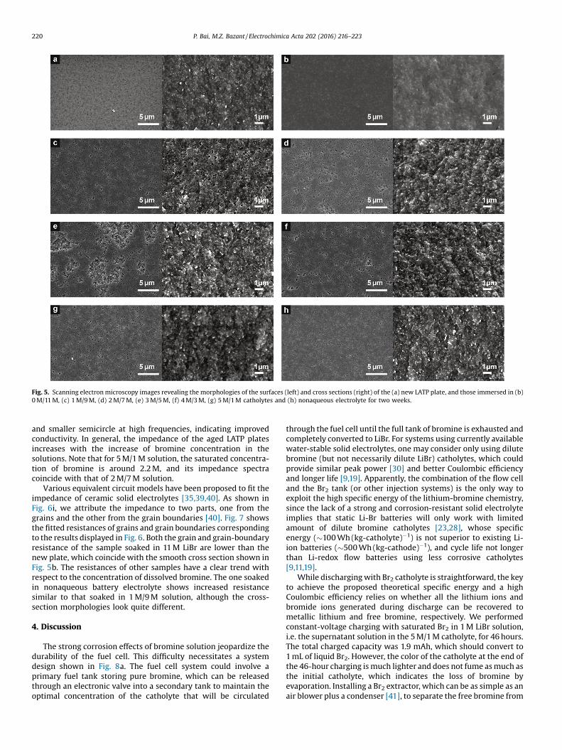
Fig. 5. Scanning electron microscopy images revealing the morphologies of the surfaces (left) and cross sections (right) of the (a) new LATP plate, and those immersed in (b)0 M/11 M, (c) 1 M/9 M, (d) 2 M/7 M, (e) 3 M/5 M, (f) 4 M/3 M, (g) 5 M/1 M catholytes and (h) nonaqueous electrolyte for two weeks.
220 P. Bai, M.Z. Bazant / Electrochimica Acta 202 (2016) 216–223
and smaller semicircle at high frequencies, indicating improvedconductivity. In general, the impedance of the aged LATP platesincreases with the increase of bromine concentration in thesolutions. Note that for 5 M/1 M solution, the saturated concentra-tion of bromine is around 2.2 M, and its impedance spectracoincide with that of 2 M/7 M solution.
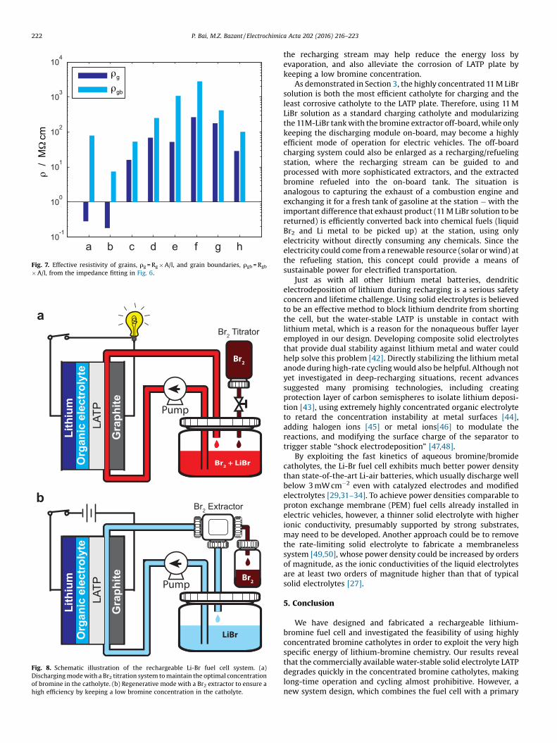
Various equivalent circuit models have been proposed to fit theimpedance of ceramic solid electrolytes [35,39,40]. As shown inFig. 6i, we attribute the impedance to two parts, one from thegrains and the other from the grain boundaries [40]. Fig. 7 showsthe fitted resistances of grains and grain boundaries correspondingto the results displayed in Fig. 6. Both the grain and grain-boundaryresistance of the sample soaked in 11 M LiBr are lower than thenew plate, which coincide with the smooth cross section shown inFig. 5b. The resistances of other samples have a clear trend withrespect to the concentration of dissolved bromine. The one soakedin nonaqueous battery electrolyte shows increased resistancesimilar to that soaked in 1 M/9 M solution, although the cross-section morphologies look quite different.
4. Discussion
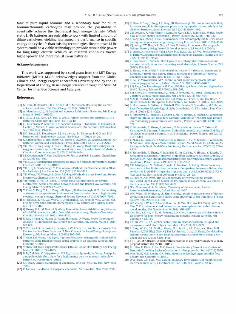
The strong corrosion effects of bromine solution jeopardize thedurability of the fuel cell. This difficulty necessitates a systemdesign shown in Fig. 8a. The fuel cell system could involve aprimary fuel tank storing pure bromine, which can be releasedthrough an electronic valve into a secondary tank to maintain theoptimal concentration of the catholyte that will be circulated
through the fuel cell until the full tank of bromine is exhausted andcompletely converted to LiBr. For systems using currently availablewater-stable solid electrolytes, one may consider only using dilutebromine (but not necessarily dilute LiBr) catholytes, which couldprovide similar peak power [30] and better Coulombic efficiencyand longer life [9,19]. Apparently, the combination of the flow celland the Br2 tank (or other injection systems) is the only way toexploit the high specific energy of the lithium-bromine chemistry,since the lack of a strong and corrosion-resistant solid electrolyteimplies that static Li-Br batteries will only work with limitedamount of dilute bromine catholytes [23,28], whose specificenergy (�100 Wh (kg-catholyte)�1) is not superior to existing Li-ion batteries (�500 Wh (kg-cathode)�1), and cycle life not longerthan Li-redox flow batteries using less corrosive catholytes[9,11,19].
While discharging with Br2 catholyte is straightforward, the keyto achieve the proposed theoretical specific energy and a highCoulombic efficiency relies on whether all the lithium ions andbromide ions generated during discharge can be recovered tometallic lithium and free bromine, respectively. We performedconstant-voltage charging with saturated Br2 in 1 M LiBr solution,i.e. the supernatant solution in the 5 M/1 M catholyte, for 46 hours.The total charged capacity was 1.9 mAh, which should convert to1 mL of liquid Br2. However, the color of the catholyte at the end ofthe 46-hour charging is much lighter and does not fume as much asthe initial catholyte, which indicates the loss of bromine byevaporation. Installing a Br2 extractor, which can be as simple as anair blower plus a condenser [41], to separate the free bromine from
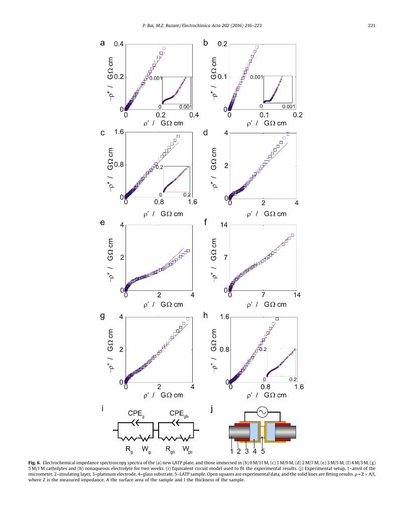
Fig. 6. Electrochemical impedance spectroscopy spectra of the (a) new LATP plate, and those immersed in (b) 0 M/11 M, (c) 1 M/9 M, (d) 2 M/7 M, (e) 3 M/5 M, (f) 4 M/3 M, (g)5 M/1 M catholytes and (h) nonaqueous electrolyte for two weeks. (i) Equivalent circuit model used to fit the experimental results. (j) Experimental setup, 1–anvil of themicrometer, 2–insulating layer, 3–platinum electrode, 4–glass substrate, 5–LATP sample. Open squares are experimental data, and the solid lines are fitting results. r = Z � A/l,where Z is the measured impedance, A the surface area of the sample and l the thickness of the sample.
P. Bai, M.Z. Bazant / Electrochimica Acta 202 (2016) 216–223 221
a b c d e f g h10
-1
100
101
102
103
104
gρ
gbρ
c/
Mm
ρΩ
Fig. 7. Effective resistivity of grains, rg = Rg� A/l, and grain boundaries, rgb = Rgb
� A/l, from the impedance fitting in Fig. 6.
Lith
ium
Org
anic
ele
ctro
lyte
Br2
Br2 + LiBr
Pump
LATP
Gra
phite
Lith
ium
Org
anic
ele
ctro
lyte
LiBr
Pump
LATP
Gra
phite Br2
Br2 Extractor
Br2 Titrator
a
b
Fig. 8. Schematic illustration of the rechargeable Li-Br fuel cell system. (a)Discharging mode with a Br2 titration system to maintain the optimal concentrationof bromine in the catholyte. (b) Regenerative mode with a Br2 extractor to ensure ahigh efficiency by keeping a low bromine concentration in the catholyte.
222 P. Bai, M.Z. Bazant / Electrochimica Acta 202 (2016) 216–223
the recharging stream may help reduce the energy loss byevaporation, and also alleviate the corrosion of LATP plate bykeeping a low bromine concentration.
As demonstrated in Section 3, the highly concentrated 11 M LiBrsolution is both the most efficient catholyte for charging and theleast corrosive catholyte to the LATP plate. Therefore, using 11 MLiBr solution as a standard charging catholyte and modularizingthe 11M-LiBr tank with the bromine extractor off-board, while onlykeeping the discharging module on-board, may become a highlyefficient mode of operation for electric vehicles. The off-boardcharging system could also be enlarged as a recharging/refuelingstation, where the recharging stream can be guided to andprocessed with more sophisticated extractors, and the extractedbromine refueled into the on-board tank. The situation isanalogous to capturing the exhaust of a combustion engine andexchanging it for a fresh tank of gasoline at the station � with theimportant difference that exhaust product (11 M LiBr solution to bereturned) is efficiently converted back into chemical fuels (liquidBr2 and Li metal to be picked up) at the station, using onlyelectricity without directly consuming any chemicals. Since theelectricity could come from a renewable resource (solar or wind) atthe refueling station, this concept could provide a means ofsustainable power for electrified transportation.
Just as with all other lithium metal batteries, dendriticelectrodeposition of lithium during recharging is a serious safetyconcern and lifetime challenge. Using solid electrolytes is believedto be an effective method to block lithium dendrite from shortingthe cell, but the water-stable LATP is unstable in contact withlithium metal, which is a reason for the nonaqueous buffer layeremployed in our design. Developing composite solid electrolytesthat provide dual stability against lithium metal and water couldhelp solve this problem [42]. Directly stabilizing the lithium metalanode during high-rate cycling would also be helpful. Although notyet investigated in deep-recharging situations, recent advancessuggested many promising technologies, including creatingprotection layer of carbon semispheres to isolate lithium deposi-tion [43], using extremely highly concentrated organic electrolyteto retard the concentration instability at metal surfaces [44],adding halogen ions [45] or metal ions[46] to modulate thereactions, and modifying the surface charge of the separator totrigger stable “shock electrodeposition” [47,48].
By exploiting the fast kinetics of aqueous bromine/bromidecatholytes, the Li-Br fuel cell exhibits much better power densitythan state-of-the-art Li-air batteries, which usually discharge wellbelow 3 mW cm�2 even with catalyzed electrodes and modifiedelectrolytes [29,31–34]. To achieve power densities comparable toproton exchange membrane (PEM) fuel cells already installed inelectric vehicles, however, a thinner solid electrolyte with higherionic conductivity, presumably supported by strong substrates,may need to be developed. Another approach could be to removethe rate-limiting solid electrolyte to fabricate a membranelesssystem [49,50], whose power density could be increased by ordersof magnitude, as the ionic conductivities of the liquid electrolytesare at least two orders of magnitude higher than that of typicalsolid electrolytes [27].
5. Conclusion
We have designed and fabricated a rechargeable lithium-bromine fuel cell and investigated the feasibility of using highlyconcentrated bromine catholytes in order to exploit the very highspecific energy of lithium-bromine chemistry. Our results revealthat the commercially available water-stable solid electrolyte LATPdegrades quickly in the concentrated bromine catholytes, makinglong-time operation and cycling almost prohibitive. However, anew system design, which combines the fuel cell with a primary
P. Bai, M.Z. Bazant / Electrochimica Acta 202 (2016) 216–223 223
tank of pure liquid bromine and a secondary tank for dilutebromine/bromide catholytes may provide the possibility toeventually achieve the theoretical high energy density. Whilestatic Li-Br batteries are only able to work with limited amount ofdilute catholytes, yielding less appealing performance in specificenergy and cycle life than existing technologies, the proposed Li-Brsystem could be a viable technology to provide sustainable powerfor long-range electric vehicles, as research continues towardhigher-power and more robust Li-air batteries.
Acknowledgements
This work was supported by a seed grant from the MIT EnergyInitiative (MITei). M.Z.B. acknowledges support from the GlobalClimate and Energy Project at Stanford University and by the USDepartment of Energy, Basic Energy Sciences through the SUNCATCenter for Interface Science and Catalysis.
References
[1] M. Tran, D. Banister, J.D.K. Bishop, M.D. McCulloch, Realizing the electric-vehicle revolution, Nat Clim Change 2 (2012) 328–333.
[2] A. Manthiram, L.J. Li, Hybrid and Aqueous Lithium-Air Batteries, Adv EnergyMater 5 (2015) 1401302.
[3] J. Lu, L. Li, J.B. Park, Y.K. Sun, F. Wu, K. Amine, Aprotic and Aqueous Li-O-2Batteries, Chem Rev 114 (2014) 5611–5640.
[4] J. Christensen, P. Albertus, R.S. Sanchez-Carrera, T. Lohmann, B. Kozinsky, R.Liedtke, J. Ahmed, A. Kojic, A Critical Review of Li/Air Batteries, J ElectrochemSoc 159 (2012) R1–R30.
[5] P.G. Bruce, S.A. Freunberger, L.J. Hardwick, J.M. Tarascon, Li-O-2 and Li-Sbatteries with high energy storage, Nat Mater 11 (2012) 19–29.
[6] G. Girishkumar, B. McCloskey, A.C. Luntz, S. Swanson, W. Wilcke, Lithium—AirBattery: Promise and Challenges, J Phys Chem Lett 1 (2010) 2193–2203.
[7] Y.G. Zhu, C. Jia, J. Yang, F. Pan, Q. Huang, Q. Wang, Dual redox catalysts foroxygen reduction and evolution reactions: towards a redox flow Li-O2 battery,Chemical Communications 51 (2015) 9451–9454.
[8] J.B. Goodenough, Y. Kim, Challenges for Rechargeable Li Batteries, Chem Mater22 (2010) 587–603.
[9] Y.H. Lu, J.B. Goodenough, Rechargeable alkali-ion cathode-flow battery, J MaterChem 21 (2011) 10113–10117.
[10] Y.H. Lu, J.B. Goodenough, Y. Kim, Aqueous Cathode for Next-Generation Alkali-Ion Batteries, J Am Chem Soc 133 (2011) 5756–5759.
[11] Y.R. Wang, Y.G. Wang, H.S. Zhou, A Li-Liquid Cathode Battery Based on a HybridElectrolyte, Chemsuschem 4 (2011) 1087–1090.
[12] Y.R. Wang, P. He, H.S. Zhou, Li-Redox Flow Batteries Based on HybridElectrolytes: At the Cross Road between Li-ion and Redox Flow Batteries, AdvEnergy Mater 2 (2012) 770–779.
[13] Y. Zhao, Y. Ding, Y. Li, L. Peng, H.R. Byon, J.B. Goodenough, G. Yu, A chemistryand material perspective on lithium redox flow batteries towards high-densityelectrical energy storage, Chemical Society Reviews 44 (2015) 7968–7996.
[14] M. Duduta, B. Ho, V.C. Wood, P. Limthongkul, V.E. Brunini, W.C. Carter, Y.M.Chiang, Semi-Solid Lithium Rechargeable Flow Battery, Adv Energy Mater 1(2011) 511–516.
[15] Q. Huang, H. Li, M. Gratzel, Q. Wang, Reversible chemical delithiation/lithiationof LiFePO4: towards a redox flow lithium-ion battery, Physical ChemistryChemical Physics 15 (2013) 1793–1797.
[16] F. Pan, J. Yang, Q. Huang, X. Wang, H. Huang, Q. Wang, Redox Targeting ofAnatase TiO2 for Redox Flow Lithium-Ion Batteries, Adv Energy Mater 4 (2014)n/a-n/a.
[17] V. Presser, C.R. Dennison, J. Campos, K.W. Knehr, E.C. Kumbur, Y. Gogotsi, TheElectrochemical Flow Capacitor: A New Concept for Rapid Energy Storage andRecovery, Adv Energy Mater 2 (2012) 895–902.
[18] Y. Zhao, L.N. Wang, H.R. Byon, High-performance rechargeable lithium-iodinebatteries using triiodide/iodide redox couples in an aqueous cathode, NatCommun 4 (2013).
[19] Y. Zhao, H.R. Byon, High-Performance Lithium-Iodine Flow Battery, Adv EnergyMater 3 (2013) 1630–1635.
[20] B. Li, Z.M. Nie, M. Vijayakumar, G.S. Li, J. Liu, V. Sprenkle, W. Wang, Ambipolarzinc-polyiodide electrolyte for a high-energy density aqueous redox flowbattery, Nat Commun 6 (2015).
[21] J.A. Dean, Lange's Handbook of Chemistry, 15th ed., McGraw-Hill, New York,1999.
[22] P. Patnaik, Handbook of inorganic chemicals, McGraw-Hill, New York, 2003.
[23] Y. Zhao, Y. Ding, J. Song, L.L. Peng, J.B. Goodenough, G.H. Yu, A reversible Br-2/Br- redox couple in the aqueous phase as a high-performance catholyte foralkaliion batteries, Energ Environ Sci 7 (2014) 1990–1995.
[24] C.P. de Leon, A. Frias-Ferrer, J. Gonzalez-Garcia, D.A. Szanto, F.C. Walsh, Redoxflow cells for energy conversion, J Power Sources 160 (2006) 716–732.
[25] Y. Yang, G.Y. Zheng, Y. Cui, A membrane-free lithium/polysulfide semi-liquidbattery for large-scale energy storage, Energ Environ Sci 6 (2013) 1552–1558.
[26] X.J. Wang, Y.Y. Hou, Y.S. Zhu, Y.P. Wu, R. Holze, An Aqueous RechargeableLithium Battery Using Coated Li Metal as Anode, Sci Rep-Uk 3 (2013).
[27] Z. Chang, X.J. Wang, Y.Q. Yang, J. Gao, M.X. Li, L.L. Liu, Y.P. Wu, Rechargeable Li//Br battery: a promising platform for post lithium ion batteries, J Mater Chem A2 (2014) 19444–19450.
[28] K. Takemoto, H. Yamada, Development of rechargeable lithium-brominebatteries with lithium ion conducting solid electrolyte, J Power Sources 281(2015) 334–340.
[29] T. Zhang, N. Imanishi, Y. Shimonishi, A. Hirano, Y. Takeda, O. Yamamoto, N.Sammes, A novel high energy density rechargeable lithium/air battery,Chemical Communications 46 (2010) 1661–1663.
[30] P. Bai, V. Viswanathan, M.Z. Bazant, A dual-mode rechargeable lithium-bromine/oxygen fuel cell, J Mater Chem A 3 (2015) 14165–14172.
[31] Z.Q. Peng, S.A. Freunberger, Y.H. Chen, P.G. Bruce, A Reversible and Higher-RateLi-O-2 Battery, Science 337 (2012) 563–566.
[32] Y.H. Chen, S.A. Freunberger, Z.Q. Peng, O. Fontaine, P.G. Bruce, Charging a Li-O-2 battery using a redox mediator, Nat Chem 5 (2013) 489–494.
[33] M.M.O. Thotiyl, S.A. Freunberger, Z.Q. Peng, Y.H. Chen, Z. Liu, P.G. Bruce, Astable cathode for the aprotic Li-O-2 battery, Nat Mater 12 (2013) 1049–1055.
[34] B. Horstmann, B. Gallant, R. Mitchell, W.G. Bessler, Y. Shao-Horn, M.Z. Bazant,Rate-Dependent Morphology of Li2O2 Growth in Li-O-2 Batteries, J Phys ChemLett 4 (2013) 4217–4222.
[35] S. Hasegawa, N. Imanishi, T. Zhang, J. Xie, A. Hirano, Y. Takeda, O. Yamamoto,Study on lithium/air secondary batteries-Stability of NASICON-type lithiumion conducting glass-ceramics with water, J Power Sources 189 (2009) 371–377.
[36] Y. Shimonishi, T. Zhang, P. Johnson, N. Imanishi, A. Hirano, Y. Takeda, O.Yamamoto, N. Sammes, A study on lithium/air secondary batteries-Stability ofNASICON-type glass ceramics in acid solutions, J Power Sources 195 (2010)6187–6191.
[37] T. Zhang, N. Imanishi, Y. Shimonishi, A. Hirano, J. Xie, Y. Takeda, O. Yamamoto,N. Sammes, Stability of a Water-Stable Lithium Metal Anode for a Lithium-AirBattery with Acetic Acid-Water Solutions, J Electrochem Soc 157 (2010) A214–A218.
[38] Y. Shimonishi, T. Zhang, N. Imanishi, D. Im, D.J. Lee, A. Hirano, Y. Takeda, O.Yamamoto, N. Sammes, A study on lithium/air secondary batteries-Stability ofthe NASICON-type lithium ion conducting solid electrolyte in alkaline aqueoussolutions, J Power Sources 196 (2011) 5128–5132.
[39] C.R. Mariappan, M. Gellert, C. Yada, F. Rosciano, B. Roling, Grain boundaryresistance of fast lithium ion conductors: Comparison between a lithium-ionconductive Li-Al-Ti-P-O-type glass ceramic and a Li(1.5)A(10.5)Ge(1.5)P(3)O(12) ceramic, Electrochem Commun 14 (2012) 25–28.
[40] P.G. Bruce, A.R. West, The Ac Conductivity of Polycrystalline Lisicon,Li2 + 2xzn1-Xgeo4, and a Model for Intergranular Constriction Resistances, JElectrochem Soc 130 (1983) 662–669.
[41] N.N. Greenwood, A. Earnshaw, Chemistry of the elements, 2nd ed,Butterworth-Heinemann, Oxford, Boston, 1997.
[42] W.C. West, J.F. Whitacre, J.R. Lim, Chemical stability enhancement of lithiumconducting solid electrolyte plates using sputtered LiPON thin films, J PowerSources 126 (2004) 134–138.
[43] G.Y. Zheng, S.W. Lee, Z. Liang, H.W. Lee, K. Yan, H.B. Yao, H.T. Wang, W.Y. Li, S.Chu, Y. Cui, Interconnected hollow carbon nanospheres for stable lithiummetal anodes, Nat Nanotechnol 9 (2014) 618–623.
[44] L.M. Suo, Y.S. Hu, H. Li, M. Armand, L.Q. Chen, A new class of Solvent-in-Saltelectrolyte for high-energy rechargeable metallic lithium batteries, NatCommun 4 (2013).
[45] Y.Y. Lu, Z.Y. Tu, L.A. Archer, Stable lithium electrodeposition in liquid andnanoporous solid electrolytes, Nat Mater 13 (2014) 961–969.
[46] F. Ding, W. Xu, G.L. Graff, J. Zhang, M.L. Sushko, X.L. Chen, Y.Y. Shao, M.H.Engelhard, Z.M. Nie, J. Xiao, X.J. Liu, P.V. Sushko, J. Liu, J.G. Zhang, Dendrite-FreeLithium Deposition via Self-Healing Electrostatic Shield Mechanism, J AmChem Soc 135 (2013) 4450–4456.
[47] J.-H. Han, M.Z. Bazant, Shock Electrodeposition in Charged Porous Media, arXivpreprint arXiv:1505.05604, (2015).
[48] J.H. Han, E. Khoo, P. Bai, M.Z. Bazant, Over-limiting Current and Control ofDendritic Growth by Surface Conduction in Nanopores, Sci. Rep. 4 (2014) 7056.
[49] W.A. Braff, M.Z. Bazant, C.R. Buie, Membrane-less hydrogen bromine flowbattery, Nat Commun 4 (2013).
[50] W.A. Braff, C.R. Buie, M.Z. Bazant, Boundary layer analysis of membranelesselectrochemical cells, J. Electrochem. Soc. 160 (2013) A2056–A2063.