Embed Size (px)
Citation preview

Performance Analysis of OTFS Modulation with ReceiveAntenna Selection
Vighnesh S Bhat, G. D. Surabhiy, and A. ChockalingamDepartment of Electrical Communication Engineering, Indian Institute of Science, Bangalore 560012
y Multimedia Communications Lab, University of Texas at Dallas, Richardson, TX 75080-3021
Abstract—In this paper, we analyze the performance of or-thogonal time frequency space (OTFS) modulation with antennaselection at the receiver, where ns out of nr receive antennaswith maximum channel Frobenius norms in the delay-Doppler(DD) domain are selected. Single-input multiple-output OTFS(SIMO-OTFS), multiple-input multiple-output OTFS (MIMO-OTFS), and space-time coded OTFS (STC-OTFS) systems withreceive antenna selection (RAS) are considered. We considerthese systems without and with phase rotation. Our diversityanalysis results show that, with no phase rotation, SIMO-OTFSand MIMO-OTFS systems with RAS are rank deficient, andtherefore they do not extract the full receive diversity as well asthe diversity present in the DD domain. Also, Alamouti codedSTC-OTFS system with RAS and no phase rotation extracts thefull transmit diversity, but it fails to extract the DD diversity.On the other hand, SIMO-OTFS and STC-OTFS systems withRAS become full-ranked when phase rotation is used, becauseof which they extract the full spatial as well as the DD diversitypresent in the system. Also, when phase rotation is used, MIMO-OTFS systems with RAS extract the full DD diversity, but they donot extract the full receive diversity because of rank deficiency.Simulation results are shown to validate the analytically predicteddiversity performance.
Index Terms—OTFS modulation, receive antenna selection,diversity, MIMO-OTFS, space-time coded OTFS.
I. INTRODUCTION
Orthogonal time frequency space (OTFS) modulation is atwo-dimensional (2D) modulation scheme proposed in therecent literature to tackle the doubly-dispersive nature ofmobile radio channels, caused by multipath propagation en-vironments [1],[2],[3]. Conventional multicarrier modulationschemes such as orthogonal frequency division multiplexing(OFDM) embed information symbols in the time-frequency(TF) domain to mitigate inter-symbol interference (ISI) causedby time dispersion. However, the Doppler shifts encounteredin high-mobility channels destroy the orthogonality amongsubcarriers in OFDM. This results in degraded performanceof OFDM systems in time-varying channels [4]. OTFS, onthe other hand, places the information symbols in delay-Doppler (DD) domain which result in 2D convolution of theinformation symbols with the channel in the DD domain.OTFS has been found to perform better than OFDM inhigh-Doppler communication scenarios, such as high-speedtrains and vehicle-to-vehicle/vehicle-to-infrastructure commu-nications. Since the signaling in OTFS is done in the DDdomain rather than in the TF domain, the interaction ofinformation symbol and rapidly time-varying channel appearas almost time invariant in the DD domain. Also, because
of the constant DD channel gain experienced by a OTFSframe, design of equalizers and channel estimation in DDdomain is easy. One more advantage of OTFS is that itcan be implemented using existing multicarrier modulationschemes, such as OFDM, with additional pre-processing andpost-processing modules [15].
Several papers in the recent literature have investigatedmany key issues in OTFS such as low-complexity signal de-tection [5]-[13], channel estimation [14]-[16], peak-to-averagepower ratio (PAPR) and pulse shapes [17]-[20], and multipleaccess [21]-[24]. In terms of performance analysis, an asymp-totic diversity analysis for OTFS has been carried out in [25].It established that the asymptotic diversity order achieved insingle-input single-output OTFS (SISO-OTFS) is one for idealbiorthogonal waveforms. In other words, OTFS in its basicform does not extract the diversity present in the DD domain.It also explored a phase rotation scheme using transcendentalnumbers to extract full diversity in the DD domain. It has alsoreported diversity orders of nr and nrP for multiple-inputmultiple-output OTFS (MIMO-OTFS) without and with phaserotation, respectively, where nr and P denote the number ofreceive antennas and the number of resolvable paths in theDD domain, respectively. The analysis in [26] on the effectivediversity of OTFS using rectangular waveforms and a two-pathchannel has shown that the number of signal pairs that preventthe achievability of full rank is very small for sufficiently largeframe sizes. The analysis in [27] for space-time coded OTFS(STC-OTFS) with Alamouti code with two transmit antennashas reported diversity orders of 2nr and 2nrP for STC-OTFSwithout and with phase rotation, respectively. Because of thegood diversity slopes in the finite signal-to-noise ratio (SNR)regime even with small frame sizes, STC-OTFS was suggestedto be suited for low-latency applications.
Antenna selection techniques allow the use of fewer radiofrequency (RF) chains than the number of antenna elements.This reduces the RF hardware complexity and cost. In thisregard, it is of interest to analyze the performance of OTFSwith antenna selection, and such an analysis has not beenreported so far. Our new and novel contributions in this papercan be highlighted as follows. First, we analyze and establishthe diversity orders achieved by different multi-antenna OTFSsystems with antenna selection at the receiver, where ns outof nr receive antennas are selected. Second, in rapidly time-varying channels, devising suitable antenna selection metricis a crucial issue. We address this issue by proposing theFrobenius norm of the channel matrix in the DD domain as

x[k, l] X [n,m] x(t) y(t) Y [n,m] y[k, l]
channelWignertransform
Heisenbergtransform
Receivewindowing& SFFT
ISFFT &transmitwindowing
Fig. 1: OTFS modulation scheme.
the antenna selection criterion. This is novel and attractivebecause it takes advantage of the simplicity of DD channelestimation in OTFS due to the sparsity and slow variation ofrapidly time-varying channels when viewed in the DD domain.
In our analysis, we consider the diversity performanceof single-input multiple-output OTFS (SIMO-OTFS), MIMO-OTFS, and STC-OTFS systems with receive antenna selection(RAS). Our diversity analysis results show that, with no phaserotation, SIMO-OTFS and MIMO-OTFS systems with RASare rank deficient, and therefore they do not extract the fullreceive diversity as well as the diversity present in the DDdomain. Also, Alamouti coded STC-OTFS system with RASand no phase rotation extracts the full transmit diversity, butit fails to extract the DD diversity. On the other hand, SIMO-OTFS and STC-OTFS systems with RAS become full-rankedwhen phase rotation is used, because of which they extract thefull spatial as well as the DD diversity present in the system.Also, when phase rotation is used, MIMO-OTFS systems withRAS extract the full DD diversity, but they do not extract thefull receive diversity because of rank deficiency. A summary ofthe diversity orders achieved in different multi-antenna OTFSsystems with RAS are presented in Table I in Sec. III. In thelater sections, we will present analytical derivations for thediversity orders in Table I and supporting simulation resultsthat verify the analytically predicted diversity orders.
The rest of the paper is organized as follows. The consideredmulti-antenna OTFS systems with receive antenna selectionare presented in Sec. II. The diversity analyses of these systemsfor full rank and rank deficient are presented in Sec. III.Numerical results and discussions are presented in Sec. IV.Conclusions are presented in Sec. V.
Notations: Capital boldface letters denote matrices, lowercase boldface letters denote vectors, diagfx1; � � � ; xng de-notes a diagonal matrix with fx1; � � � ; xng as its diagonalentries, and kXk denotes the Frobenius norm of matrix X.Transpose and Hermitian operators are denoted by (�)T and(�)H , respectively. jcj and jSj denote the magnitude of thecomplex scalar c and size of the set S, respectively. E[�] andTr[�] denote the expectation and trace operations, respectively.CN (a; b) denotes complex Gaussian distribution with mean aand variance b.
II. MULTI-ANTENNA OTFS SYSTEMS WITH RAS
In this section, we present the basic OTFS modulationscheme and the system models corresponding to differentmulti-antenna OTFS systems. The analyses that follow in Sec.III are for integer Dopplers/delays, and the case of fractionalDoppler/delays will be analyzed in the Appendix.
A. Basic OTFS modulationThe OTFS modulation scheme consists of cascaded struc-
tures of two 2D transforms at the transmitter and the receiver.The block diagram of the basic OTFS modulation schemeis shown in Fig. 1. At the transmitter, information symbolsin the DD domain are mapped to TF domain using inversesymplectic finite Fourier transform (ISFFT) followed by win-dowing. The TF symbols are then converted to time domainusing Heisenberg transform for transmission over the channel.At the receiver, Wigner transform (inverse of Heisenbergtransform) is performed to get TF symbols. Using windowingand symplectic finite Fourier transform (SFFT), TF symbolsare mapped back to DD domain for demodulation.
The information symbols x[k; l]s are multiplexed on an N�M DD grid, given by
� = f( kNT ;
lM�f ); k = 0; � � � ; N�1; l = 0; � � � ;M�1g; (1)
where 1=NT and 1=M�f denote the bin sizes in the Dopplerdomain and delay domain, respectively, and N and M denotethe number of Doppler and delay bins, respectively. The DDdomain symbols x[k; l]s are mapped to symbols in the TFdomain X[n;m]s using ISFFT. Assuming rectangular window-ing, the TF signal can be written as
X[n;m] =1pMN
N�1Xk=0
M�1Xl=0
x[k; l]ej2�(nkN�ml
M ): (2)
This TF signal is converted into a time domain signal x(t),using Heisenberg transform and transmit pulse gtx(t), as
x(t) =
N�1Xn=0
M�1Xm=0
X[n;m]gtx(t� nT )ej2�m�f(t�nT ): (3)
The transmitted signal x(t) passes through the channel, whosecomplex baseband channel response in the DD domain, de-noted by h(�; �), is given by [6]
h(�; �) =
PXi=1
hi�(� � �i)�(� � �i); (4)
where P is the number of paths in the DD domain, and hi,�i, and �i denote the channel gain, delay, and Doppler shift,respectively, associated with the ith path. The received timedomain signal y(t) at the receiver is then given by
y(t) =
Z�
Z�
h(�; �)x(t� �)ej2��(t��)d�d� + v(t); (5)
where v(t) denotes the additive white Gaussian noise.At the receiver, the received signal y(t) is matched filtered
with a receive pulse grx(t), yielding the cross-ambiguityfunction Agrx;y(t; f) given by
Agrx;y(t; f) =
Zg�rx(t
0 � t)y(t0)e�j2�f(t0�t)dt0: (6)

The pulses gtx(t) and grx(t) are chosen such that the biorthog-onality condition is satisfied, i.e., Agrx;gtx(t; f)jnT;m�f =�(m)�(n). Sampling Agrx;y(t; f) at t = nT , f = m�f gives
Y [n;m] = Agrx;y(t; f)jt=nT;f=m�f : (7)
This received TF domain signal Y [n;m] is mapped to thecorresponding DD domain signal y[k; l] using SFFT as
y[k; l] =1pMN
N�1Xk=0
M�1Xl=0
Y [n;m]e�j2�(nkN�ml
M ): (8)
From (3)-(8), the input-output relation in the DD domain canbe written as [6]
y[k; l] =
PXi=1
h0ix[(k � �i)N ; (l � �i)M ] + v[k; l]; (9)
where h0i = hie�j2��i�i , �i and �i are assumed to be integers
corresponding to the indices of the delay tap and Dopplerfrequency associated with �i and �i, respectively, i.e., �i ,�i
M�f and �i , �iNT , (:)N denotes the modulo N operation, and
v[k; l] denotes the additive white Gaussian noise. Vectorizingthe input-output relation in (9), we can write [6]
y = Hx+ v; (10)
where H 2 CMN�MN , x;y;v 2 CMN�1, the (k + Nl)thentry of x, xk+Nl = x[k; l], k = 0; � � � ; N�1, l = 0; � � � ;M�1 and x[k; l] 2 A, where A is the modulation alphabet (e.g.,quadrature amplitude modulation (QAM) or phase shift keying(PSK)). Likewise, yk+Nl = y[k; l] and vk+Nl = v[k; l], k =0; � � � ; N � 1; l = 0; � � � ;M � 1. It is assumed that the hisare i.i.d and are distributed as CN (0; 1=P ), assuming uniformscattering profile.
An alternate form of input-output relation (10): The vector-ized form of input-output relation in (10) can be written in analternate form which is essential for our diversity analysis.This alternate representation is also useful in writing thesystem model for STC-OTFS systems. Towards this, it isobserved that there are only P non-zero entries in each rowand column of the equivalent channel matrix H because of themodulo operations in (9), i.e., there are only MNP non-zeroentries in H. Also, among the non-zero entries there are onlyP unique values, since each transmitted symbol experiencesthe same channel gain as can be seen in (9). With this, therelation in (10) can be written in an alternate form as [25]
yT = h0X+ vT ; (11)
where yT is 1 � MN received vector, h0 is 1 � P vectorwhose ith entry is given by h0i = hie
�j2��i�i , vT is 1�MNnoise vector, and X is P � MN matrix whose ith columnX[i], i = k + Nl; k = 0; � � � ; N � 1; l = 0; � � � ;M � 1, isgiven by
X[i] =
26664x(k��1)N+N(l��1)Mx(k��2)N+N(l��2)M
...x(k��P )N+N(l��P )M
37775 : (12)
This representation allows us to view the matrix X in the formof P �MN symbol matrix.
B. MIMO-OTFS with receive antenna selection
The input-output relation of MIMO-OTFS system with nrreceive antennas and nt transmit antennas can be written as264 y1...ynr
375
| {z }, �y
=
264H11 � � � H1nt
.... . .
...Hnr1 � � � Hnrnt
375
| {z }, �H
264 x1...xnt
375
| {z }, �x
+
264 v1...vnr
375
| {z }, �v
; (13)
or equivalently�y = �H�x+ �v; (14)
where �y 2 CnrMN�1 is the received signal vector, �H 2CnrMN�ntMN is the overall equivalent channel matrix withHij being the MN � MN equivalent channel matrix be-tween the jth transmit antenna and ith receive antenna, �x 2CntP�MN is the OTFS transmit vector, and �v 2 CnrMN�1
is the noise vector. Perfect DD channel knowledge is assumedat the receiver. The receiver selects ns out of the nr antennaswith the largest Frobenius norms of the channel in the DDdomain, i.e., selects the ns antennas whose Frobenius normsamong those of all the nr antennas, given by
ntXj=1
kHijk2; i = 1; 2; � � � ; nr; (15)
are the largest. Observing that each Hij contains only PMNnon-zero elements with P unique elements and using thedefinition of Frobenius norm, the selection metric in (15) canbe written as
PXk=1
ntXj=1
jh(k)ij j2; i = 1; 2; � � � ; nr; (16)
where h(k)ij are the unique non-zero entries of Hij . Therefore,with antenna selection, the input-output relation of the MIMO-OTFS system can be written as264 y
01...y0ns
375
| {z }, �y0
=
264H
011 � � � H0
1nt...
. . ....
H0ns1 � � � H0
nsnt
375
| {z }, �H0
264 x1...xnt
375
| {z }, �x0
+
264 v
01...v0ns
375
| {z }, �v0
; (17)
or equivalently�y0 = �H0�x+ �v0; (18)
where �y0 2 CnsMN�1, �H0 2 CnsMN�ntMN is the equivalentchannel matrix with antenna selection, �x 2 CntMN�1 isthe OTFS transmit vector, and �v0 2 CnsMN�1 is the noisevector. Figure 2 shows the block diagram of MIMO-OTFSwith receive antenna selection.
An alternate form of MIMO-OTFS with antenna selection:The input-output relation in (18) can be written in an alternateform similar to that in (11), by observing that each H0
ij in(17) contains only P unique non-zero elements and hence �H0
in (18) contains only Pnsnt unique non-zero elements witheach row having only Pnt unique non-zero elements and each
X1[n,m]
X2[n,m]
Xnt[n,m]
Heisenberg
transform
x1(t)
x2(t)
xnt(t)
ISFFT &transmitwindowing
Heisenberg
transform
ISFFT &transmitwindowing
Heisenberg
transform
ISFFT &transmitwindowing
b
b
b
b
b
b
x1[k, l]
x2[k, l]
xnt[k, l]
b
b
b
y1(t)
y2(t)Antenna
selectionns out of
nr
h11(τ, ν)
h21(τ, ν)
h12(τ, ν)
h1nt(τ, ν) hnr1
(τ, ν)ynr
(t)
Wignertransform
Wigner
transform
Receivewindowing& SFFT
Receivewindowing& SFFT
y′1(t)
y′ns(t)
b
b
b
Y ′
1[n,m]
Y ′
ns[n,m]
x1[k, l]
xns[k, l]
Fig. 2: MIMO-OTFS with receive antenna selection.
column having only nsP unique non-zero elements. Therefore,(17) can be written as264y
01T
...y0ns
T
375
| {z }, ~Y
=
264 h
011 � � � h01nt...
. . ....
h0ns1 � � � h0nsnt
375
| {z }, ~H
264X1
...Xnt
375
| {z }, ~X
+
264v
01T
...v0ns
T
375
| {z }, ~V
; (19)
or equivalently~Y = ~H~X+ ~V; (20)
where ~Y 2 Cns�MN with its ith row corresponding to the re-ceived signal in the ith selected receive antenna, ~H 2 Cns�ntP
is the channel matrix with h0ij 2 C1�P containing P uniquenon-zero entries of H0
ij , ~X is ntP �MN symbol matrix, and~V 2 Cns�MN is the noise matrix.
C. STC-OTFS with antenna selection
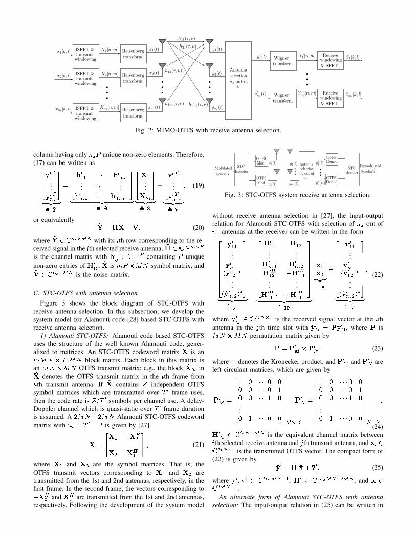
Figure 3 shows the block diagram of STC-OTFS withreceive antenna selection. In this subsection, we develop thesystem model for Alamouti code [28] based STC-OTFS withreceive antenna selection.
1) Alamouti STC-OTFS: Alamouti code based STC-OTFSuses the structure of the well known Alamouti code, gener-alized to matrices. An STC-OTFS codeword matrix ~X is anntMN � T 0MN block matrix. Each block in this matrix isan MN �MN OTFS transmit matrix; e.g., the block ~Xkt in~X denotes the OTFS transmit matrix in the tth frame fromkth transmit antenna. If ~X contains Z independent OTFSsymbol matrices which are transmitted over T 0 frame uses,then the code rate is Z=T 0 symbols per channel use. A delay-Doppler channel which is quasi-static over T 0 frame durationis assumed. A 2MN �2MN Alamouti STC-OTFS codewordmatrix with nt = T 0 = 2 is given by [27]
~X =
24X1 �XH
2
X2 XH1
35 ; (21)
where X1 and X2 are the symbol matrices. That is, theOTFS transmit vectors corresponding to X1 and X2 aretransmitted from the 1st and 2nd antennas, respectively, in thefirst frame. In the second frame, the vectors corresponding to�XH
2 and XH1 are transmitted from the 1st and 2nd antennas,
respectively. Following the development of the system model
Modulated
symbols
STCEncoder
OTFSMod
OTFSMod
OTFSDemod
Antennaselectionns out of
nr OTFSDemod
STCdecoder
Demodulated
Symbols
x1(t)
x2(t)
bbb
bbb
y1(t)
ynr(t)
y′1(t)
y′ns
(t)
Fig. 3: STC-OTFS system receive antenna selection.
without receive antenna selection in [27], the input-outputrelation for Alamouti STC-OTFS with selection of ns out ofnr antennas at the receiver can be written in the form2666666664
y011...
y0ns1(y012)
�...
(y0ns2)�
3777777775
| {z }, �y0
=
2666666664
H011 H0
12...
...H0
ns1 H0ns2
H0H12 �H0H
11...
...H0H
ns2 �H0Hns1
3777777775
| {z }, �H0
�x1x2
�| {z }, �x
+
2666666664
v011...
v0ns1(v012)
�...
(v0ns2)�
3777777775
| {z }, �v0
;(22)
where y0ij 2 CMN�1 is the received signal vector at the ithantenna in the jth time slot with y0ij = Py0ij , where P isMN �MN permutation matrix given by
P = P0M P0N ; (23)
where denotes the Kronecker product, and P0M and P0N areleft circulant matrices, which are given by
P0M =
26666641 0 � � � 0 00 0 � � � 0 10 0 � � � 1 0...0 1 � � � 0 0
3777775M�M
P0N =
26666641 0 � � � 0 00 0 � � � 0 10 0 � � � 1 0...0 1 � � � 0 0
3777775N�N
;
(24)H0
ij 2 CMN�MN is the equivalent channel matrix betweenith selected receive antenna and jth transmit antenna, and xi 2CMN�1 is the transmitted OTFS vector. The compact form of(22) is given by
�y0 = �H0�x+ �v0; (25)
where �y0; �v0 2 C2nsMN�1, �H0 2 C2nsMN�2MN , and �x 2C2MN�1.
An alternate form of Alamouti STC-OTFS with antennaselection: The input-output relation in (25) can be written in

an alternate form, based on (11) and (19), as264 y
0T11 y0T12...
...y0Tns1 y0Tns2
375
| {z }, ~Y
=
264 h
011 h012...
...h0ns1 h0ns2
375
| {z }, ~H
�X1 �(X2)
�
X2 (X1)�
�| {z }
, ~X
+
264v0T11 v0T12
......
v0Tns1 v0Tns2
375
| {z }, ~V
;
(26)
which can be written in the following compact form1:
~Y = ~H~X+ ~V; (27)
where ~Y; ~V 2 Cns�2MN , ~H 2 Cns�2P , and ~X 2 C2P�2MN .Here it is observed that Xi 6= Xi, since transmitted OTFSvectors in the 2nd frame are conjugated and permuted vectorsof those transmitted in the 1st frame. In (21), ~X is defined tobe 2MN � 2MN symbol matrix, but for diversity analysis~X 2 C2P�2MN in (26) is convenient.
D. OTFS with phase rotation
In this subsection, we present OTFS modulation with phaserotation. In OTFS with phase rotation, the OTFS vector x ispre-multiplied by a phase rotation matrix �, which is of theform
� = diagf�0; �1; � � � ; �MN�1g: (28)
That is, x0 = �x is the phase rotated OTFS transmit vector. Ithas been shown in [25] that SISO-OTFS with the above phaserotation achieves the full diversity available in the DD domainwhen �i = ejai , i = 0; 1; � � � ;MN � 1, are transcendentalnumbers with ai being real, distinct and algebraic. We considerthis phase rotation scheme for multi-antenna OTFS systems,where the OTFS vector in each transmit antenna is pre-multiplied by the phase rotation matrix �.
E. Rank of multi-antenna OTFS systems
In the next section, we carry out the diversity analysis formulti-antenna systems for full rank and rank deficient cases. Inthis subsection, we identify the rank of the considered multi-antenna OTFS systems without and with phase rotation.
1) MIMO-OTFS, SIMO-OTFS: Consider MIMO-OTFS(nt � 2) without phase rotation. Let ~Xi and ~Xj be twodistinct symbol matrices defined in (20). The minimum rankof (~Xi � ~Xj) is 1 < min(ntP;MN) [25]. Therefore,MIMO-OTFS without phase rotation is rank deficient. Next,consider MIMO-OTFS with phase rotation. Let �x0i = ��xi and�x0j = ��xj be two distinct phase rotated OTFS transmit vectorsin (18). Let ~X0
i and ~X0j be the corresponding phase rotated
symbol matrices in (20). The minimum rank of (~X0i � ~X0
j)
1In order to adopt a unified input-output system model in the analysis,we keep the same notation in (20) and (27), where in MIMO-OTFS withoutspace-time coding in (20), we have ~Y, ~V 2 Cns�MN , ~H 2 Cns�ntP and~X 2 CntP�MN , and in space-time coded OTFS in (27), we have ~Y, ~V2 Cns�2MN , ~H 2 Cns�2P and ~X 2 C2P�2MN .
is P < min(ntP;MN) [25]. Therefore, MIMO-OTFS systemwith phase rotation is also rank deficient.
SIMO-OTFS can be viewed as a special case of MIMO-OTFS with nt = 1. Therefore, for SIMO-OTFS without phaserotation, the minimum rank of (~Xi� ~Xj) is 1 < min(P;MN).Therefore, SIMO-OTFS system without phase rotation is rankdeficient for P > 1. For P = 1, the dimension of (~Xi � ~Xj)is 1 � MN and the minimum rank is 1, and so it is fullrank. For SIMO-OTFS with phase rotation, the minimum rankof (~X0
i � ~X0j) is P = min(P;MN). Since P � MN and
minimum rank is P , and so it is full rank.2) STC-OTFS: Consider Alamouti STC-OTFS without
phase rotation. Let ~Xi and ~Xj be the two distinct symbolmatrices defined in (27), The minimum rank of (~Xi � ~Xj)is 2 < min(2P; 2MN) [27]. Therefore, for P > 1 AlamoutiSTC-OTFS is rank deficient, and for P = 1 it is full rankwith rank 2. For Alamouti STC-OTFS with phase rotation,the minimum rank of (~X0
i � ~X0j) is 2P � min(2P; 2MN)
[27]. Therefore, Alamouti STC-OTFS with phase rotation isfull rank with rank 2P .
III. ANALYSIS OF MULTI-ANTENNA OTFS WITH RAS
In this section, we analyze the performance of multi-antennaOTFS systems with RAS by deriving explicit upper bounds onpairwise error probability (PEP). We carry out the diversityanalysis for full rank and rank deficient cases in the followingsubsections.
A. Full rank multi-antenna OTFS systems with RAS
Consider the case of full rank multi-antenna OTFS systemswith receive antenna selection. Let ~Xi and ~Xj be two distinctsymbol matrices. Assuming perfect DD channel knowledgeand maximum likelihood (ML) detection at the receiver, theconditional PEP between the symbol matrices ~Xi and ~Xj ,assuming ~Xi to be the transmitted symbol matrix, is given by
P (~Xi ! ~Xj j~H; ~Xi) = Q
0@sk~H(~Xi � ~Xj)k2
2N0
1A; (29)
where Q(x) = 1p2�
R1xe�t
2=2dt. For convenience, the entriesof ~X are normalized so that average energy per symbol timeis one and the SNR, denoted by , is given by = 1=N0.Therefore, (29) can be written as
P (~Xi ! ~Xj j~H; ~Xi) = Q
0@s k~H(~Xi � ~Xj)k2
2
1A: (30)
Averaging over the distribution of ~H and upper bounding usingChernoff bound, an upper bound on the unconditional PEP canbe written as
P (~Xi ! ~Xj) � E~H
"exp
� k
~H(~Xi � ~Xj)k24
!#: (31)

The distribution of ~H is given by [29],[30]
f~H(h01; � � � ;h0ns) =
nr!
(nr � ns)!ns!
�� nsXl=1
"1� e�Pkh
0lk2
ntP�1Xk=0
P kkh0lk2kk!
#nr�ns
� I ~Hl(h01; � � � ;h0ns)
�� P
Pntns
�Pntnse�P (kh
01k2+���+kh0nsk
2);
(32)where h0i is the ith row of ~H, I ~Hl
(h01; � � � ;h0ns) is the indicatorfunction given by
I ~Hl(h01; � � � ;h0ns) =
(1 if (h01; � � � ;h0ns) 2 ~Hl
0 else;(33)
and the region ~Hl is defined as ~Hl = fh01; � � � ;h0ns : kh0lk <kh0kk; k = 1; � � � ; l � 1; l + 1; � � � ; nsg. The PEP bound canbe written as
P (~Xi ! ~Xj) �nsXl=1
Z~Hl
e� 4 k~H(~Xi�~Xj)k2 nr!
(nr � ns)!ns!
� 1� e�Pkh
0lk2
ntP�1Xk=0
P kkh0lk2kk!
!nr�ns
� PnsntP
�nsntPe�P (kh
01k2+���+kh0nsk
2)dh01 � � � dh0ns :(34)
LettingpPh0l = sl, l = 1; � � � ; ns, S to be an ns�ntP matrix
whose lth row is sl and region ~Hl = fs1; � � � ; sns : kslk <kskk; k = 1; � � � ; l � 1; l + 1; � � � ; nsg, we can write (34) as
P (~Xi ! ~Xj) �nsXl=1
Z~Hl
e� 4P kS(~Xi�~Xj)k2 nr!
(nr � ns)!ns!
� 1� e�kslk
2ntP�1Xk=0
kslk2kk!
!nr�ns
� (pP )nsntP
�nsntPe�(ks1k
2+���+ksnsk2)ds1 � � � dsns :(35)
The term kS(~Xi � ~Xj)k2 in (35) can be simplified as
kS(~Xi � ~Xj)k2 = TrfS(~Xi � ~Xj)(~Xi � ~Xj)HSHg
= TrfSU�(SU)Hg
=
ntPXk=1
�kkckk2; (36)
where (36) uses the eigenvalue decomposition of (~Xi �~Xj)(~Xi � ~Xj)
H , U is the unitary matrix whose columnsare the eigenvectors of (~Xi � ~Xj)(~Xi � ~Xj)
H , � is thediagonal matrix containing its eigenvalues, and ck is the kthcolumn of SU. Let c0l be the lth row of SU so that ~Hl =fc01; � � � ; c0ns : kc0lk < kc0kk; k = 1; � � � ; l � 1; l + 1; � � � ; nsg.Defining K , ntP and � , (
pP )nsntP , and changing
variables in (35) by substituting cij = sij for i = 1; � � � ; ns
and j = 1; � � � ; ntP , we get
P (~Xi ! ~Xj) � � � nr!(nr � ns)!ns!
�nsXl=1
Z~Hl
e� 4P (�1(jc11j2+���+jcns1j2)+���+�K(jc1K j2+���+jcnsK j2))
� 1� e�(jcl1j
2+���+jclK j2)K�1Xk=0
(jcl1j2 + � � �+ jclK j2)kk!
!nr�ns
� 1
�nsKe�Pns
i=1
PKj=1 jcij j2dc11 � � � dcnsK : (37)
Evaluating the integral in (37) over the region is difficult. Butbecause of symmetry of pdf it is possible to evaluate over thewhole space which results in an upper bound. Because of thesymmetry of the pdf, the integral over ~Hl for each l is same.The lth term in (37) can be rewritten using standard integrationas
Il = � � nr!(nr � ns)!ns!
Z 1
0
� � �Z 1
0
� e� 4P (�1(jc11j2+���+jcns1j2)+���+�K(jc1K j2+���+jcnsK j2))
� 1� e�(jcl1j
2+���+jclK j2)K�1Xk=0
(jcl1j2 + � � �+ jclK j2)kk!
!nr�ns
� 1
�nsKe�Pns
i=1
PKj=1 jcij j2dc11 � � � dcnsK : (38)
Changing the variables cij = �ijej�ij , i = 1; � � � ; ns, j =
1; � � � ;K (with differential element dcij = �ijd�ijd�ij), afterevaluating integral w.r.t d�ij over [0; 2�], we get
Il = 2nsK� � nr!(nr � ns)!ns!
�Z 1
0
� � �Z 1
0
e� 4P (�1(�
211+���+�2ns1)+���+�K(�21K+���+�2nsK))
� 1� e�(�
2l1+���+�2lK)
K�1Xk=0
(�2l1 + � � �+ �2lK)k
k!
!nr�ns
� e�Pns
i=1
PKj=1 �
2ij�11 � � ��nsKd�11 � � � d�nsK : (39)
Substituting �2ij = vij , i = 1; � � � ; ns, j = 1; � � � ;K, we get
Il = � � nr!(nr � ns)!ns!
�Z 1
0
� � �Z 1
0
e� 4P (�1(v11+���+vns1)+���+�K(v1K+���+vnsK))
� 1� e�(vl1+���+vlK)
K�1Xk=0
(vl1 + � � �+ vlK)k
k!
!nr�ns
� e�Pns
i=1
PKj=1 vijdv11 � � � dvnsK : (40)
Now, (40) can be written as
Il = � � nr!(nr � ns)!ns!
Z 1
0
� � �Z 1
0
e� 4P
PKi=1 �i(
Pnsd=1;d6=l vdi) � e�(
PKi=1
Pnsd=1;d6=l vdi)
�KYi=1
nsYd=1;d 6=l
dvdi �Z 1
0
� � �Z 1
0
e� 4P
PKi=1 �ivli
� 1� e�(vl1+���+vlK)
K�1Xk=0
(vl1 + � � �+ vlK)k
k!
!nr�ns
� e�(vl1+���+vlK)dvl1 � � � dvlK :(41)
Let I(1)l denote the first integral and I(2)l denote the sec-ond integral in the above expression. Evaluating I(1)l usingR10e��xdx = 1
� , we get
I(1)l =
1QK
i=1(1 + �i4P )
!ns�1
; (42)
and I(2)l as
I(2)l =
Z 1
0
� � �Z 1
0
e� 4P
PKi=1 �ivli
� 1� e�(vl1+���+vlK)
K�1Xk=0
(vl1 + � � �+ vlK)k
k!
!nr�ns
� e�(vl1+���+vlK)dvl1 � � � dvlK :(43)
Let g(u) = 1 � e�uPK�1
m=0um
m! be the incomplete Gammafunction satisfying g(u) � uK
K! for u > 0. Upper bounding theRHS of (43) by uK
K! with u = vl1 + � � �+ vlK in (43), we canwrite
I(2)l � 1
(K!)nr�ns
Z 1
0
� � �Z 1
0
e� 4P
PKi=1 �ivli
� (vl1 + � � �+ vlK)K(nr�ns)e�(vl1+���+vlK)dvl1 � � � dvlK :(44)
We observe that
(vl1 + � � �+ vlK)K(nr�ns) =KX
i1=1
� � �KX
iK(nr�ns)=1
vli1 � � � vliK(nr�ns); (45)
where index ik in vlik takes values from the set � =f1; � � � ;Kg with k 2 f1; � � � ;K(nr � ns)g. Let the in-dex j appear mj times among the subscripts of the termvli1 � � � vliK(nr�ns)
in (45). Then,
vli1 � � � vliK(nr�ns)=
KYj=1
(vlj)mj (46)
such thatPK
j=1mj = K(nr � ns). Using (45) and (46) in(44) and changing the order of summation and integration, we
get
I(2)l � 1
(K!)nr�ns
KXi1=1
� � �KX
iK(nr�ns)=1
��Z 1
0
� � �Z 1
0
e�PK
i=1( �i4P +1)vli
KYi=1
(vli)midvl1 � � � dvlK
�:
(47)
UsingR10xne�axdx = n!
an+1 , (47) can be written as
I(2)l � 1
(K!)nr�ns
� KXi1=1
� � �KX
iK(nr�ns)=1
� m1! � � �mK !
(1 + �14P )m1+1 � � � (1 + �K
4P )mK+1
�: (48)
Using (48) and (42) in (41), Il can be written as
Il � � � nr!(nr � ns)!ns!(K!)nr�ns
1QK
i=1(1 + �i4P )
!ns�1
KXi1=1
� � �KX
iK(nr�ns)=1
m1! � � �mK !
(1 + �14P )m1+1 � � � (1 + �K
4P )mK+1:
(49)
The above bound is independent of l. Therefore, substituting(49) in (37), we can write
P (~Xi ! ~Xj)
� � � nr!(nr � ns)!(ns � 1)!(K!)nr�ns
1QK
i=1(1 + �i4P )
!ns�1
�KX
i1=1
� � �KX
iK(nr�ns)=1
m1! � � �mK !
(1 + �14P )m1+1 � � � (1 + �K
4P )mK+1:
(50)
In the high SNR regime, with some algebraic manipulations,we can write
P (~Xi ! ~Xj) � � � nr!(nr � ns)!(ns � 1)!(K!)nr�ns
1�QKi=1 �i
�ns�� KXi1=1
� � �KX
iK(nr�ns)=1
m1! � � �mK !
�m11 � � ��mK
K
�
��
4P
��PKi=1mi+1 �
4P
��K(ns�1):
(51)
Finally, substitutingPK
i=1mi = K(nr � ns) in (51), we get
P (~Xi ! ~Xj) � � � nr!(nr � ns)!(ns � 1)!(K!)nr�ns
� 1�QKi=1 �i
�ns �� KXi1=1
� � �KX
iK(nr�ns)=1
m1! � � �mK !
�m11 � � ��mK
K
�
��
4P
��Knr: (52)

Note that the inequality (52) implies that a diversity order ofnrK (= nrntP ) is achieved in a full rank multi-antenna OTFSsystem when ns antennas are selected at the receiver. We cannow specialize the above diversity result for the consideredmulti-antenna OTFS systems which are full rank as follows.
� SIMO-OTFS systems without phase rotation for P = 1and with phase rotation for P > 1 are full rank.Therefore, in these cases, full spatial and DD diversity ofnrP is achieved when ns receive antennas are selected.
� STC-OTFS systems with Alamouti code without phaserotation for P = 1 and with phase rotation for P > 1are also full rank. Therefore, in these cases, full spatialand DD diversity of 2nrP is achieved when ns receivedantennas are selected.
The above diversity results have been summarized in Table I.
B. Rank deficient multi-antenna OTFS systems with RAS
Consider the case of rank deficient multi-antenna OTFSsystems with receive antenna selection. Let ~Xi and ~Xj betwo distinct symbol matrices. Let r < K be the minimumrank of (~Xi � ~Xj). For rank deficient case, the diversityanalysis follows from (37)-(49), except now �1; � � � ; �r > 0,�r+1 =; � � � ;= �K = 0. Therefore, in the high SNR regime,the average PEP between ~Xi and ~Xj , assuming ~Xi to be thetransmitted symbol matrix, is given by
P (~Xi ! ~Xj) � � � nr!(nr � ns)!(ns � 1)!(K!)nr�ns
� 1
(Qr
i=1 �i)ns �
� KXi1=1
� � �KX
iK(nr�ns)=1
m1! � � �mK !
�m11 � � ��mr
r
�
4P
��Pri=1mi
���
4P
��rns: (53)
SincePK
i=1mi = K(nr�ns), it follows that 0 �Pri=1mi �
K(nr�ns). It is observed that the term in the square bracketsis function of
4P and there exist terms i1 � � � iK(nr�ns) suchthat
Pri=1mi = 0. Regrouping the terms in (53), we can write
P (~Xi ! ~Xj) � � � nr!(nr � ns)!(ns � 1)!(K!)nr�ns
1
(Qr
i=1 �i)ns0
@K(nr�ns)Xj=0
j
�
4P
��j1A ��
4P
��rns;
(54)
where j =Pr
i=1mi and j is the sum of the terms multiply-ing
� 4P
��Pri=mi with the same exponents. For sufficiently
high SNRs, the term� 4P
��jvanishes for
Pri=1mi > 0. Thus,
we have
P (~Xi ! ~Xj) � � � nr!(nr � ns)!(ns � 1)!(K!)nr�ns
� 1
(Qr
i=1 �i)ns 0 �
�
4P
��rns:
(55)
The above expression shows that a diversity order of nsr isachieved for a rank deficient multi-antenna OTFS system whenns antennas are selected at the receiver. We specialize the
OTFS system # ant.selected
# DD Diversity orderpaths without PR with PR
SIMO-OTFS, ns � 1 P = 1 nr nrnr � 1 P > 1 ns nrP
MIMO-OTFS, ns � nt P � 1 ns nsPnr � ntSTC-OTFS (Alamouti) ns � 1 P = 1 2nr 2nrnt = 2, nr � 1 P > 1 2ns 2nrP
TABLE I: Summary of diversity order results for multi-antenna OTFS systems with RAS.
above diversity result for the considered multi-antenna OTFSsystems which are rank deficient as follows.
� The minimum rank of (~Xi � ~Xj) is 1 for SIMO-OTFS (P > 1) and MIMO-OTFS (P � 1) systemswithout phase rotation. Therefore, these systems achievea diversity of ns when ns antennas are selected at thereceiver.
� For MIMO-OTFS (P � 1) systems with phase rotation,the minimum rank of (~Xi � ~Xj) is P , which is rankdeficient. Therefore, these systems achieve a diversity ofnsP when ns receive antennas are selected.
� For STC-OTFS (P > 1) systems with Alamouti codewithout phase rotation, the minimum rank of (~Xi � ~Xj)is 2, which is rank deficient. Therefore, these systemsachieve a diversity of 2ns when ns receive antennas areselected.
The above diversity results have been summarized in Table I.
IV. SIMULATION RESULTS
In this section, we present simulation results on the biterror performance that validate the analytical diversity resultsderived in the previous section. We evaluate the bit error rate(BER) of the considered multi-antenna OTFS systems withoutand with phase rotation for P = 1; 2; 4 and ns � 1. Thesimulation parameters used are listed in Table II.
SIMO-OTFS (without phase rotation) for P = 1: Figure4 shows the simulated BER performance of SIMO-OTFSwithout phase rotation for P = 1, M = N = 2, ns = 1,nr = 1; 2; 3; 4, BPSK, and ML detection. A carrier frequencyof 4 GHz, subcarrier spacing of 3.75 kHz, and a maximumspeed of 506.2 km/h are considered. The considered carrierfrequency and maximum speed correspond to a maximumDoppler of 1.875 kHz. The DD channel model is as per (4)and the DD profiles for different values of P are presentedin Table II. The considered system is full rank and theanalytically predicted diversity order is nr (refer Table I andSec. III-A). The BER plots in Fig. 4 show that the systemindeed achieves first, second, third, and fourth order diversityslopes for nr = 1; 2; 3; and 4, respectively, corroborating theanalytically predicted diversity orders.
SIMO-OTFS (without phase rotation) for P > 1: Figure 5shows the simulated BER performance of SIMO-OTFS with-out phase rotation for P = 4, M = N = 2, ns = 1, nr = 1; 4,BPSK, and ML detection. Other simulation parameters areas given in Table II. In addition to the simulated BER plot,upper bound and lower bounds on the bit error performanceare also plotted. The upper bound on the bit error probability

Parameter ValueCarrier frequency, fc(GHz) 4Subcarrier spacing, �f(kHz) 3.75DD profile for P = 1(�i (sec), �i (Hz)) ( 1
M�f, 1
NT)
DD profile for P = 2& M = 2; 4, N = 2 (0; 0), ( 1
M�f, 1
NT)
DD profile for P = 2& M = 4, N = 4 ( 1
M�f, 1
NT), ( 2
M�f, 2
NT)
DD profile for P = 4& M = 2, N = 2 (0; 0), (0; 1
NT), ( 1
M�f; 0), ( 1
M�f, 1
NT)
Maximum speed (km/h) 506.2Modulation scheme BPSK, 16-QAM
TABLE II: Simulation parameters.
0 5 10 15 20 25
SNR in dB
10-10
10-8
10-6
10-4
10-2
100
Bit error rate
Fig. 4: BER performance of SIMO-OTFS without phaserotation for P = 1, M = N = 2, ns = 1, and nr = 1; 2; 3; 4.
is obtained from PEP using union bound, as
Pb � 1
LntMN log2 jAjLXi=1
LXj=1;j 6=i
P ( ~Xi ! ~Xj); (56)
where L = jAntMN j. The lower bound is obtained basedon summing the PEPs corresponding to all the pairs Xi
and Xj such that the difference matrix (Xi �Xj) has rankone [25]. The considered system is rank deficient and theanalytically predicted diversity order is ns (refer Sec. III-Band Table I). Since the number of antennas selected is ns = 1,the predicted diversity order is 1. We can make two keyobservations from Fig. 5. First, the diversity slope is onefor both nr = 1 and nr = 4. Second, The upper bound,lower bound, and simulated BER almost merge at high SNRs.These observations validate the simulation results as well theanalytically predicted diversity order.
SIMO-OTFS (without and with phase rotation) for P > 1:Figure 6 shows the BER performance of SIMO-OTFS withoutand with phase rotation for P = 2, M = N = 4, ns = 1,nr = 1; 2, BPSK, ML detection, and other parameters as inTable II. For P > 1, SIMO-OTFS without phase rotation isrank deficient and the analytical diversity order is ns. Withphase rotation, the system is full-ranked and it has a diversityorder of nrP (refer Sec. III-B, Sec. III-A, and Table I). Forthe considered system, the predicted diversity orders are 1 and
0 5 10 15 20 25 30 35 40
SNR in dB
10-6
10-4
10-2
100
Bit e
rro
r r
ate
Fig. 5: BER performance of SIMO-OTFS without phaserotation for P = 4, M = N = 2, ns = 1, and nr = 1; 4.
0 5 10 15 20 25 30
SNR in dB
10-8
10-6
10-4
10-2
100
Bit e
rror r
ate
Fig. 6: BER performance of SIMO-OTFS without and withphase rotation for P = 2, M = N = 4, ns = 1, and nr = 1; 2.
4 for without and with phase rotation, respectively. The slopesin the BER plots in Fig. 6 are observed to be in line with thepredicted diversity orders.
SIMO-OTFS (without and with phase rotation) for 16-QAM:Figure 7 shows the BER performance of SIMO-OTFS withoutand with phase rotation for 16 QAM, P = 2, M = N = 2,ns = 1, nr = 1; 2, ML detection, and other parameters as inTable II. For P > 1, the analytically predicted diversity ordersfor the considered SIMO-OTFS system without and with phaserotation are 1 (ns) and 4 (nrP ), respectively. In Fig. 7, thediversity slopes are found to follow these diversity orders.
Alamouti STC-OTFS (without and with phase rotation) forP > 1: Figure 8 shows the BER performance of AlamoutiSTC-OTFS without phase rotation for P = 2, M = N = 2,nt = 2, ns = 1; 2, nr = 1; 2; 3, BPSK, ML detection, andother parameters as in Table II. From Fig. 8, it is observedthat the achieved diversity order is 2 for ns = 1 and 4for ns = 2. This corroborates with the predicted diversityorder of 2ns, the system being rank deficient. For the aboveAlamouti STC-OTFS system, Fig. 9 shows the performancewith phase rotation. This system with phase rotation is full-ranked with a predicted diversity order of 2nrP . The diversity

0 5 10 15 20 25 30 35 40
SNR in dB
10-8
10-6
10-4
10-2
100
Bit e
rror r
ate
Fig. 7: BER performance of SIMO-OTFS without and withphase rotation for P = 2, M = N = 2, ns = 1, nr = 1; 2,and 16-QAM.
0 5 10 15 20 25SNR in dB
10-10
10-8
10-6
10-4
10-2
100
Bit e
rro
r r
ate
Fig. 8: BER performance Alamouti STC-OTFS without phaserotation for P = 2, M = N = 2, nt = 2, ns = 1; 2, andnr = 1; 2; 3.
slopes observed in Fig. 9 are in accordance with this analyticalprediction.
MIMO-OTFS (without and with phase rotation) for P >1: Figure 10 shows the BER performance of MIMO-OTFSwithout and with phase rotation for P = 2, M = 4, N = 2,nt = 2, ns = 2, nr = 2; 3, BPSK, and other parameters as inTable II. The considered systems are rank deficient, and thepredicted diversity orders are ns and nsP for without and withphase rotation, respectively. It can be seen in Fig. 10 that, aspredicted, MIMO-OTFS without phase rotation achieves 2ndorder diversity slope and with phase rotation achieves 4th orderdiversity slope.
V. CONCLUSIONS
We analyzed the diversity performance of receive antennaselection in multi-antenna OTFS systems. Antennas were se-lected based on the maximum channel Frobenius norms in theDD domain. Our diversity analysis results showed that, with nophase rotation, SIMO-OTFS and MIMO-OTFS systems withRAS are rank deficient, and therefore they do not extract the
0 5 10 15 20 25
SNR in dB
10-10
10-8
10-6
10-4
10-2
100
Bit e
rro
r r
ate
Fig. 9: BER performance of Alamouti STC-OTFS with phaserotation for P = 2, M = N = 2, nt = 2, ns = 1, andnr = 1; 2.
0 5 10 15 20 25
SNR in dB
10-8
10-6
10-4
10-2
100
Bit e
rror r
ate
Fig. 10: BER performance of MIMO-OTFS without and withphase rotation for P = 2, M = 4, N = 2, nt = 2, ns = 2,and nr = 2; 3.
full receive diversity as well as the diversity present in the DDdomain. Also, Alamouti coded STC-OTFS system with RASand no phase rotation was shown to extract the full transmitdiversity, but it failed to extract the DD diversity. On the otherhand, SIMO-OTFS and STC-OTFS systems with RAS becomefull-ranked when phase rotation is used, because of which theyextracted the full spatial as well as the DD diversity presentin the system. When phase rotation is used, MIMO-OTFSsystems with RAS was shown to extract the full DD diversity,but they did not extract the full receive diversity becauseof rank deficiency. Detailed simulation results validated theanalytically predicted diversity performance.
APPENDIXANALYSIS FOR FRACTIONAL DELAYS AND DOPPLERS
A. Input-Output relation with fractional delays and Dopplers
Considering the channel representation in DD defined in (4)with non-zero fractional delays and Dopplers, we have
�i =�i + aiM�f
; �i =�i + biNT
; (57)

where �i = [�iM�f ]�, �i = [�iNT ]�, [:]� denotes the
rounding operator (nearest integer), �i, �i are assumed to beintegers corresponding to the indices of the delay tap andDoppler frequency associated with �i and �i, respectively,and ai, bi are the fractional delay and Doppler satisfying� 1
2 < ai; bi � 12 . The DD channel with fractional delays
and Dopplers, assuming rectangular window functions, can bewritten as
h(�; �) =
PXi=1
hie�j2��i�iG(�; �i)F(�; �i); (58)
where
G(�; �i) ,N�1Xn0=0
e�j2�(���i)n0T ;
F(�; �i) ,
M�1Xm0=0
ej2�(���i)m0�f :
(59)
The input-output relation with fractional delay-Doppler can bewritten as [25]
y[k; l] =
PXi=1
M�1Xq=0
N�1Xq0=0
�ej2�(�q�ai) � 1
Mej2�M(�q�ai) �M
�
�
e�j2�(�q0�bi) � 1
Ne�j2�N(�q0�bi) �N
!hie
�j2��i�i
� x[(k � �i + q0)N ; (l � �i + q)M ]:
(60)
Vectorizing the input-output relation in (60), we can write
y = Hx+ v; (61)
where y 2 CMN�1 is the received signal vector, x 2 CMN�1
transmit signal vector, H 2 CMN�MN is the equivalentchannel matrix, and v 2 CMN�1 is the noise vector.
Based on (60), the input-output relation with receive anten-nas selection in (18) can be extended to fractional delays andDopplers, as
�y0 = �H0�x+ �v0; (62)
where �y0 2 CnsMN�1 is the received signal vector, �H0 2CnsMN�ntMN is the channel matrix with antenna selection,�x 2 CntMN�1 is the OTFS transmit vector, and �v0 2CnsMN�1 is the noise vector.
B. Diversity analysis for P = 1
The selection rule in (15) and (16) are equivalent for P = 1.Therefore, for diversity analysis for P = 1, the input-outputrelation in (62) can be written in an alternate form as
~Y = ~H~X+ ~V; (63)
where ~Y 2 Cns�MN with its ith row corresponding to the re-ceived signal in the ith selected receive antenna, ~H 2 Cns�ntis the channel matrix whose (i; j)th element is hije�j2��� , ~Xis nt �MN symbol matrix whose ith column ~X[i] is givenby (64) shown at the top of next page, and ~V 2 Cns�MN isthe noise matrix.
1) Full rank case: Let ~Xi and ~Xj be two distinct symbolmatrices. The conditional PEP between ~Xi and ~Xj , assumingperfect DD channel knowledge and ML detection, is given by
P (~Xi ! ~Xj j~H; ~Xi) = Q
0@sk~H(~Xi � ~Xj)k2
2N0
1A: (65)
Upper bounding (65) using Chernoff bound and averaging overthe distribution of ~H, the unconditional PEP can be written as
P (~Xi ! ~Xj) � E~H
"exp
� k
~H(~Xi � ~Xj)k24
!#: (66)
The distribution of ~H is given in (32). Therefore, the PEP canbe written as
P (~Xi ! ~Xj) �nsXl=1
Z~Hl
e� 4 k~H(~Xi�~Xj)k2 nr!
(nr � ns)!ns!
� 1� e�kh
0lk2
nt�1Xk=0
kh0lk2kk!
!nr�ns
� 1
�nsnte�(kh
01k2+���+kh0nsk
2)dh01 � � � dh0ns :(67)
Following the steps from (35)-(52) in Sec. III-A, we can writePEP as
P (~Xi ! ~Xj) � nr!
(nr � ns)!(ns � 1)!(nt!)nr�ns
� 1
(Qnt
i=1 �i)ns �
� ntXi1=1
� � �ntX
int(nr�ns)=1
m1! � � �mnt !
�m11 � � ��mnt
nt
�
�� 4
��ntnr: (68)
The above equation shows that, for fractional delay-Doppleralso, diversity of nrnt is achieved when ns antennas areselected at the receiver. Therefore, full spatial diversity isachieved for a full rank multi-antenna OTFS system. We canspecialize the above generalized result for multi-antenna OTFSsystems which are full rank for P = 1, as follows.
� SIMO-OTFS system for P = 1 is full rank. Therefore,for this system, full spatial diversity of nr is achievedwhen ns antennas are selected at the receiver.
� STC-OTFS system with Alamouti code for P = 1 is alsofull rank. Therefore, this system also achieves full spatialdiversity of 2nr when ns receive antennas are selected.
2) Rank deficient case: Let ~Xi and ~Xj be two distinctsymbol matrices. Let r be the minimum rank of (~Xi-~Xj) and�1; � � � ; �r > 0, �r+1 = � � � = �nt = 0 be the eigenvaluesof the matrix (~Xi� ~Xj)(~Xi� ~Xj)
H . Following the diversityanalysis for integer delay-Doppler in Sec. III-B, we can obtainthe PEP expression as
P (~Xi ! ~Xj) � nr!
(nr � ns)!(ns � 1)!(nt!)nr�ns1
(Qr
i=1 �i)ns 0 �
� 4
��rns: (69)
The above expression shows that, for the rank deficient case,diversity of nsr is achieved when ns antennas are selected at

X[i] =
26666666664
PM�1q=0
PN�1q0=0
�ej2�(�q�a)�1
Mej2�M
(�q�a)�M
� �e�j2�(�q
0�b)�1Ne�j
2�N
(�q0�b)�N
�x1[(k � � + q0)N ; (l � �+ q)M ]
PM�1q=0
PN�1q0=0
�ej2�(�q�a)�1
Mej2�M
(�q�a)�M
� �e�j2�(�q
0�b)�1Ne�j
2�N
(�q0�b)�N
�x2[(k � � + q0)N ; (l � �+ q)M ]
...PM�1q=0
PN�1q0=0
�ej2�(�q�a)�1
Mej2�M
(�q�a)�M
� �e�j2�(�q
0�b)�1Ne�j
2�N
(�q0�b)�N
�xnt [(k � � + q0)N ; (l � �+ q)M ]
37777777775: (64)
0 5 10 15 20 25
SNR in dB
10-8
10-6
10-4
10-2
100
Bit error rate
Fig. 11: BER performance of SIMO-OTFS without phaserotation for M = N = 2, P = 1, ns = 1, and nr = 1; 2; 3; 4,with fractional delay and Doppler.
the receiver. MIMO-OTFS system with P = 1 is rank deficientwith minimum rank one. Therefore, diversity of ns is achievedwhen ns antennas are selected in MIMO-OTFS.
C. Simulation results
In this subsection, we present the simulation results forfractional delays and Dopplers. For all the simulation resultspresented in this subsection, the fractional delays and Dopplersare generated as follows. The Doppler shift correspondingto ith channel tap is generated using Jakes formula [6]�i = �max cos(�i), where �max is the maximum Dopplershift and �i is uniformly distributed over [��; �]. The delaycorresponding to ith channel tap is generated as uniformlydistributed over [0; (M � 1)Ts], where Ts = 1=(M�f) and�f is the subcarrier spacing. Exponential power delay profileand Jakes Doppler spectrum are considered [31].
Figure 11 shows the simulated bit error performance ofSIMO-OTFS without phase rotation for M = 2, N = 2,P = 1, ns = 1, nr = 1; 2; 3; 4, BPSK, and ML detection. Thecarrier frequency, subcarrier spacing, and maximum Dopplerconsidered are 4 GHz, 3.75 kHz, and 1.875 kHz, respectively.From Fig. 11, it is seen that system achieves 1st, 2nd, 3rd,and 4th order diversity for nr = 1; 2; 3; and 4, respectively,verifying analytically predicted diversity orders.
For the case of P > 1 with fractional delays and Dopplers,the selection rule in (15) and (16) are not equivalent. There-fore, it is difficult to find the distribution of ~H because of
0 5 10 15 20 25
SNR in dB
10-6
10-4
10-2
100
Bit e
rro
r r
ate
Fig. 12: BER performance comparison between SIMO-OTFSwith RAS and SIMO-OFDM with RAS for M = 64, N = 12,P = 8, ns = 1, nr = 1; 2, MMSE detection, and fractionaldelays/Dopplers.
spreading of channel coefficients in multiple DD bins, leadingto intractability of analysis. Consequently, for P > 1, wepresent simulation results. For this, we consider simulationparameters according to IEEE 802.11p standard for wirelessaccess in vehicular environments (WAVE) [32] and long termevolution (LTE) standard [33]. Also, rectangular pulse shapesare used. Since the values of M and N are large, ML detectionis not feasible. Therefore, we have used minimum mean squareerror (MMSE) detection and message passing (MP) detection[6]. Also, in these figures, we present a comparison betweenthe performance of SIMO/MIMO-OTFS and SIMO/MIMO-OFDM with RAS.
Performance in IEEE 802.11p with rectangular pulse: Here,we present a performance comparison between SIMO-OTFSand SIMO-OFDM with RAS considering system parametersaccording to IEEE 802.11p standard [32] as follows. Thecarrier frequency and subcarrier spacing are taken to be 5.9GHz and 0.156 MHz, respectively. A frame size of M = 64,N = 12, number of paths P = 8, and a maximum speedof 220 km/h (corresponding maximum Doppler of 1.2 kHz),and BPSK modulation are considered. Figure 12 shows theperformance comparison between SIMO-OTFS with rectan-gular pulse and SIMO-OFDM for M = 64, N = 12, P = 8,ns = 1, nr = 2, and MMSE detection. From Fig. 12, weobserve that the performance of SIMO-OTFS with RAS issignificantly better than that of SIMO-OFDM with RAS. Forexample, at a BER of 10�3, SIMO-OTFS with RAS has an

0 2 4 6 8 10 12
SNR in dB
10-3
10-2
10-1
Bit e
rro
r r
ate
Fig. 13: BER performance comparison between MIMO-OTFSwith RAS and MIMO-OFDM with RAS for M = 12, N =7, P = 5, nt = 2, ns = 2, nr = 2; 3, MP detection, andfractional delays/Dopplers.
SNR gain of about 11 dB compared to SIMO-OFDM withRAS.
Performance in LTE with rectangular pulse: Here, wepresent a performance comparison between MIMO-OTFS andMIMO-OFDM with RAS considering system parameters ac-cording to LTE standard [33] as follows. The carrier frequencyand subcarrier spacing are taken to be 4 GHz and 15 kHz,respectively. A frame size of M = 12, N = 7, P = 5,and a maximum speed of 500 km/h (corresponding maximumDoppler of 1.85 kHz), and BPSK modulation are considered.Figure 13 shows the performance comparison between MIMO-OTFS with rectangular pulse and MIMO-OFDM for M = 12,N = 7, P = 5, nt = 2, ns = 2, nr = 2; 3, andMP detection. From Fig. 13, we observe that MIMO-OTFSwith RAS performs better than MIMO-OFDM with RAS. Wefurther note that while the performance for P > 1 in Figs.12 and 13 are observed through simulations, an analyticalderivation of the diversity orders for P > 1 with RAS for thefractional delay-Doppler case is open for future investigation.
REFERENCES
[1] W. C. Jakes, Microwave Mobile Communications, New York: IEEE Press,reprinted, 1994.
[2] R. Hadani, S. Rakib, M. Tsatsanis, A. Monk, A. J. Goldsmith, A. F.Molisch, and R. Calderbank, “Orthogonal time frequency space modula-tion,” Proc. IEEE WCNC’2017, pp. 1-7, Mar. 2017.
[3] R. Hadani, S. Rakib, S. Kons, M. Tsatsanis, A. Monk, C. Ibars,J. Delfeld, Y. Hebron, A. J. Goldsmith, A. F. Molisch, and R.Calderbank, “Orthogonal time frequency space modulation,” [Online]https://arxiv.org/abs/1808.00519, 1 Aug 2018.
[4] T. Wang, J. G. Proakis, E. Masry, and J. R. Zeidler, “Performancedegradation of OFDM systems due to Doppler spreading,” IEEE Trans.Wireless Commun., vol. 5, no. 6, pp. 1422-1432, Jun. 2006.
[5] A. Farhang, A. R. Reyhani, L. E. Doyle, and B. Farhang-Boroujeny, “Lowcomplexity modem structure for OFDM-based orthogonal time frequencyspace modulation,” IEEE Wireless Commun. Lett., vol. 7, no. 3, pp. 344-347, Jun. 2018.
[6] P. Raviteja, K. T. Phan, Y. Hong, and E. Viterbo, “Interference can-cellation and iterative detection for orthogonal time frequency spacemodulation,” IEEE Trans. Wireless Commun., vol. 17, no. 10, pp. 6501-6515, Aug. 2018.
[7] M. K. Ramachandran and A. Chockalingam, “MIMO-OTFS in high-Doppler fading channels: signal detection and channel estimation,” Proc.IEEE GLOBECOM’2018, Dec. 2018.
[8] S. Tiwari, S. S. Das, and V. Rangamgari, “Low complexity LMMSEreceiver for OTFS,” IEEE Commun. Lett., vol. 23, no. 12, pp. 2205-2209,Dec. 2019.
[9] T. Thaj and E. Viterbo, “Low Complexity iterative rake decision feedbackequalizer for zero-padded OTFS systems,” IEEE Trans. Veh. Tech., doi:10.1109/TVT.2020.3044276 (early access), 14 Dec. 2020.
[10] H. Qu, G. Liu, L. Zhang, S. Wen, and M. A. Imran, “Low-complexitysymbol detection and interference cancellation for OTFS system,” IEEETrans. Commun., doi: 10.1109/TCOMM.2020.3043007 (early access), 7Dec. 2020.
[11] L. Gaudio, M. Kobayashi, G. Caire, and G. Colavolpe, “On the effective-ness of OTFS for joint radar parameter estimation and communication,”IEEE Trans. Commun., vol. 19, no. 9, pp. 5951-5965, Jun. 2020.
[12] W. Xu, T. Zou, H. Gao, Z. Bie, Z. Feng, and Z. Ding, “Low-complexitylinear equalization for OTFS systems with rectangular waveforms,” [On-line] https://arxiv.org/abs/1911.08133, 19 Nov. 2019.
[13] G. D. Surabhi and A. Chockalingam, “Low-complexity linear equal-ization for OTFS modulation,” IEEE Commun. Lett., vol. 24, no. 2, pp.330-334, Feb. 2020.
[14] P. Raviteja, K. T. Phan, and Y. Hong, “Embedded pilot-aided channelestimation for OTFS in delay-Doppler channels,” IEEE Trans. Veh. Tech.,vol. 68, no. 5, pp. 4906-4917, May 2019.
[15] W. Shen, D. Lai, J. An, P. Fan, and R. W. Heath, “Channel estimation fororthogonal time frequency space (OTFS) massive MIMO,” IEEE Trans.Signal Process., vol. 67, no. 16, pp. 4204-4917, May 2019.
[16] Rasheed O K, G. D. Surabhi, and A. Chockalingam, “Sparse delay-Doppler channel estimation in rapidly time-varying channels for multiuserOTFS on the uplink,” Proc. IEEE VTC2020-Spring, May 2020.
[17] G. D. Surabhi, R. M. Augustine, and A. Chockalingam, “Peak-to-averagepower ratio of OTFS modulation,” IEEE Commun. Lett., vol. 23, no. 6,pp. 999-1002, Jun. 2019.
[18] S. Tiwari and S. S. Das, “Circularly pulse shaped orthogonal timefrequency space modulation,” Electron. Lett., vol. 56, no. 3, pp. 157-160,6 Feb. 2020.
[19] S. Gao and J. Zheng, “Peak-to-average power ratio reduction in pilot-embedded OTFS modulation through iterative clipping and filtering,”IEEE Commun. Lett., doi: 10.1109/LCOMM.2020.2993036 (early ac-cess), 7 May 2020.
[20] P. Raviteja, Y. Hong, E. Viterbo, and E. Biglieri, “Practical pulse shapingwaveforms for reduced-cyclic-prefix OTFS,” IEEE Trans. Veh. Tech., vol.68, no. 1, pp. 957-961, Jan. 2019.
[21] S. Rakib and R. Hadani, “Multiple access in wireless telecom-munications system for high-mobility applications,” US Patent No.US9722741B1, Aug. 2017.
[22] V. Khammammetti and S. K. Mohammed, “OTFS based multiple-access in high Doppler and delay spread wireless channels,” IEEE Trans.Wireless Commun., vol. 8, no. 2, pp. 528-531, Apr. 2019.
[23] R. M. Augustine and A. Chockalingam, “Interleaved time-frequencymultiple access using OTFS modulation,” Proc. IEEE VTC’2019 (Fall),Sep. 2019.
[24] Z. Ding, R. Schober, P. Fan, and H. V. Poor, “OTFS-NOMA: anefficient approach for exploiting heterogeneous user mobility profiles,”IEEE Trans. Commun., vol. 67, no. 11, pp. 7950-7965, Nov. 2019.
[25] G. D. Surabhi, R. M. Augustine, and A. Chockalingam, “On thediversity of uncoded OTFS modulation in doubly-dispersive channels,”IEEE Trans. Wireless Commun., vol. 18, no. 6, pp. 3049-3063, Jun. 2019.
[26] P. Raviteja, Y. Hong, E. Viterbo, and E. Biglieri, “Effective diversity ofOTFS modulation,” IEEE Commun. Lett., vol. 9, no. 6, pp. 249-253, Nov.2019.
[27] R. M. Augustine, G. D. Surabhi, and A. Chockalingam, “Space-time coded OTFS modulation in high-Doppler channels,” Proc. IEEEVTC’2019-Spring, pp. 1-6, 2019.
[28] S. M. Alamouti, “A simple transmit diversity technique for wirelesscommunications,” IEEE J. Sel. Areas in Commun., vol. 16, no. 8, pp.1451-1458, Oct. 1998.
[29] I. Bahceci, T. M. Duman, and Y. Altunbasak, “Antenna selection formultiple-antenna transmission systems: performance analysis and codeconstruction,” IEEE Trans. Inform. Theory, vol. 49, no. 10, pp. 2669-2681, Oct. 2003.
[30] I. Bahceci, T. M. Duman, and Y. Altunbasak, “Correction to “AntennaSelection for multiple-antenna transmission systems: performance analy-sis and code construction,” ” IEEE Trans. Inform. Theory, vol. 54, no.12, pp. 5788-5789, Dec. 2008.

[31] F. Hlawatsch and G. Mats, Wireless Communications Over Rapidly Time-Varying Channels, New York, USA: Academic, 2011.
[32] A. M. S. Abdelgader, and W. Lenan, “The physical layer of theIEEE 802.11 p WAVE communication standard: the specifications andchallenges,” Proc. World Congr. Eng. Comput. Sci., pp. 22-24, Oct. 2014.
[33] ETSI TS 136 211 V8.7.0 (2009-06) – LTE; Evolved Universal TerrestrialRadio Access (E-UTRA); Physical channels and modulation.