Embed Size (px)
Citation preview

Performance analysis of device to device
communication based on LTE
http://www.sfu.ca/~shimengl/ENSC894/
Team #2
Simone Liu, [email protected], 301155308
Adam Tanbouz, [email protected], 200131768
SIMON FRASER UNIVERSITY
ENSC 894 G100 SPECIAL TOPICS II: COMMUNICATION NETWORKS
Spring 2017
Prof. Ljiljana Trajokovic
Copyright in this work rests with the author. Please ensure that any reproduction or re-use is done in accordance with the relevant national copyright legislation.

ii
Abstract
Unlike traditional cellular network, D2D (Device-to-device) communication allows
mobile user equipment (UE) in proximity to communicate directly via
licensed/unlicensed band without routing through the Base Station (BS) or core
network. D2D communication in LTE network will have many potential
advantages including increasing spectral efficiency of the network, reducing
transmission delay and network overloading. In this project, we will investigate
how D2D communications benefits users, and analyze the performance of D2D
communications in LTE network comparing to traditional cellular network.
Keywords: Device-to-device communication; Long term evolution (LTE); LTE
Direct

iii
Acknowledgements
We would like to thank our course instructor, Dr. Ljiljana Trajkovic, who
gave us incredible lectures and provided us valuable feedback and guidance to
our project. We would like to thank the teaching assistant, Mr. Zhida Li for his
support to the course.
We would also like to thank the ns-3 community and all the contributors for
building and maintaining the opensource software.

iv
Table of Contents
Abstract ........................................................................................................................... ii
Acknowledgements ........................................................................................................ iii
Table of Contents ........................................................................................................... iv
List of Tables ................................................................................................................... v
List of Figures................................................................................................................. vi
List of Acronyms ............................................................................................................ vii
Chapter 1. Introduction .............................................................................................. 1
1.1. Motivation .............................................................................................................. 1
1.2. Scope .................................................................................................................... 1
Chapter 2. LTE and D2D ............................................................................................. 3
Chapter 3. Implementation ........................................................................................ 4
3.1. Scenario Creation .................................................................................................. 4
3.1.1. Simulation Base Station Unavailable ............................................................. 4
3.1.2. Simulation High Volume Traffic ...................................................................... 8
3.2. Simulation and Results ........................................................................................ 11
3.2.1. Simulation Base Station Unavailable ........................................................... 11
3.2.2. Simulation High Volume Traffic .................................................................... 13
Chapter 4. Discussion and conclusion ................................................................... 18
4.1. Base Station Unavailable Scenario ...................................................................... 18
4.2. High Volume Traffic Scenario .............................................................................. 18
4.3. Conclusions ......................................................................................................... 19
4.4. Challenges and Future work ................................................................................ 19
References ................................................................................................................... 20
Appendix ...................................................................................................................... 21

v
List of Tables
Table 1Attributes of Base Station Unavailable scenario simulation without D2D communication ......................................................................................... 7
Table 2 Attributes of Base Station Unavailable scenario simulation with D2D communication ......................................................................................... 7
Table 3 Simulation results of Base Station Unavailable scenario simulation without D2D communication ....................................................................................... 11
Table 4 Simulation results of Base Station Unavailable scenario simulation with D2D communication ....................................................................................... 12
Table 5 Simulation results of High Volume Traffic scenario simulation without D2D communication ....................................................................................... 13
Table 6 Simulation results of High Volume Traffic scenario simulation with D2D communication ....................................................................................... 14
Table 7 Attributes of High Volume Traffic scenario simulation without D2D communication ....................................................................................... 21
Table 8 Attributes of High Volume Traffic scenario simulation with D2D communication ............................................................................................................... 21
Table 9 Simulation results of user1 to user 2 High Volume Traffic scenario simulation without D2D communication ................................................................... 22
Table 10 Simulation results of user3 to user 2 High Volume Traffic scenario simulation without D2D communication ................................................................... 22
Table 11 Simulation results of user4 to user 2 High Volume Traffic scenario simulation without D2D communication ................................................................... 23
Table 12 Simulation results of user1 to user 2 High Volume Traffic scenario simulation with D2D communication ........................................................................ 23
Table 13 Simulation results of user3 to user 2 High Volume Traffic scenario simulation with D2D communication ........................................................................ 23
Table 14 Simulation results of user4 to user 2 High Volume Traffic scenario simulation with D2D communication ........................................................................ 24
Table 15 Simulation results of Base Station Unavailable scenario simulation with different simulation time ......................................................................... 24
Table 16 Rx Packet VS Simulation time of High Volume Traffic scenario simulation ..... 24
Table 17 Throughput VS Simulation time of High Volume Traffic scenario simulation ... 24
Table 18 Delay Sum VS Simulation time of High Volume Traffic scenario simulation .... 25
Table 19 Rx Packet VS Max Packet Size of High Volume Traffic scenario simulation ... 25
Table 20 Throughput VS Max Packet Size of High Volume Traffic scenario simulation . 25
Table 21 Delay Sum VS Max Packet Size of High Volume Traffic scenario simulation .. 25

vi
List of Figures
Figure 1 Scenario 1: Base Station Unavailable, Scenario 2: High Volume Traffic ............ 2
Figure 2 Topology of Base Station Unavailable scenario simulation without D2D communication (using NetAnim) ............................................................... 5
Figure 3 Topology of Base Station Unavailable scenario simulation with D2D communication (using NetAnim) ............................................................... 5
Figure 4 Process of Base Station Unavailable scenario simulation without D2D communication ......................................................................................... 6
Figure 5 Process of Base Station Unavailable scenario simulation with D2D communication ......................................................................................... 6
Figure 6 Topology of High Volume Traffic scenario simulation without D2D communication (using NetAnim) ............................................................... 9
Figure 7 Topology of High Volume Traffic scenario simulation with D2D communication (using NetAnim) ....................................................................................... 9
Figure 8 Network flow of High Volume Traffic scenario simulation without D2D communication (using PhyViz) ............................................................... 10
Figure 9 Network flow of High Volume Traffic scenario simulation with D2D communication (using PhyViz) ............................................................... 10
Figure 10 Received packet bytes comparison with increasing simulation time Base Station Unavailable scenario .................................................................. 12
Figure 11 Throughput comparison with increasing simulation time Base Station Unavailable scenario .............................................................................. 13
Figure 12 Received packet bytes comparison with increasing simulation time of High volume traffic scenario ........................................................................... 14
Figure 13 Throughput at user 2 comparison with increasing simulation time of High volume traffic scenario ........................................................................... 15
Figure 14 Delay sum comparison with increasing simulation time of High volume traffic scenario ................................................................................................. 15
Figure 15 Received packet bytes comparison with different max packet size of High volume traffic scenario ........................................................................... 16
Figure 16 Throughput at user 2 comparison with different max packet size of High volume traffic scenario ........................................................................... 16
Figure 17 Delay Sum comparison with different max packet size of High volume traffic scenario ................................................................................................. 17
vii
List of Acronyms
3GPP 3𝑟𝑑 Generation Partnership Project
D2D Device-to-Device
eNB (eNodeB) Enhanced node B (Base Station)
EPC Evolved Packet Core
E-UTRAN Evolved Universal Terrestrial Radio Access
LTE Long Term Evolution
MTU Maximum Transmission Unit
PDN Packet Data Network
PGW Packet Data Network Gateway
UE User Equipment
1
Chapter 1. Introduction
1.1. Motivation
With the growing demand of wireless communication and high data rate service,
Device-to-device (D2D) communications was proposed in cellular networks to
improve network performance. In D2D communications, the user equipment
(UEs) in close proximity are allowed to directly communicate between each other
by reusing the cellular resources rather than the support of base station. D2D
communication, thus, enhances spectrum utilization, increases cellular capacity
and improves the user throughput [1]. In addition, D2D communication provides
extended coverage, by enabling wireless communication in closed distance when
cellular network infrastructure is unavailable [2]. Our motivation is to identify the
use cases that D2D communication brings to the user and analyze the
performance of the use cases with comparison to the traditional cellular network.
1.2. Scope
In this project, we would like to simulate the use case where cellular network
infrastructure is unavailable or out of range, and analyze the performance
improvement of D2D network with regular peer to peer communication.
We then define two scenarios.
1. For two users in short distance, simulate the network flow when base
station is available and when base station is not available, with and
without D2D communication.
2. For four users attached to one base station, two of them are in short
distance, simulate the network performance with and without D2D
communication.

2
For the first scenario, by simply comparing the amount of received packets with
and without D2D communication enabled, we can see D2D communication will
continue service after the base station is unavailable.
For the second scenario, we will compare the statistics results getting from the
NS-3 simulator. In particular, we are interested in the delay time, throughput and
total received packets of user equipment. We will simulate with different
simulation time, and different packet size, to investigate the performance
improvement on D2D communication over traditional cellular network and
discuss the use case which suitable for D2D communication.
The following figures show the graphical representation of the two scenarios.
D2D
eNB
Data Path
Figure 1 Scenario 1: Base Station Unavailable, Scenario 2: High Volume Traffic
D2D
eNB
Data Path Offloading Path
D2D D2D
3
Chapter 2. LTE and D2D
Today, major growth driver of 4G LTE Market includes growing technology
advancement in telecommunication industry, growing demand for high speed
communication network and growing development of smart devices among
others [3]. With the mobile industry shipping more smartphones and tablets than
PCs; success stories of social networking services like Facebook becoming a
social trend from which mobile users developed the need to be connected
anywhere to their surroundings, the industry is looking at an exploding number of
more than thousand billion wireless connections around the world in 2020.
In telecommunication, Long-Term Evolution (LTE) is a standard for high-speed
wireless communication for mobile phones and data terminals, based on the
GSM/EDGE and UMTS/HSPA technologies. According to the history of LTE’s
development [4], LTE is commonly marketed as 4G LTE, but it does not meet the
technical criteria of a 4G wireless service. The LTE Advanced standard formally
satisfies the ITU-R requirements to be considered IMT-Advanced. To
differentiate LTE Advanced and WiMAX-Advanced from current 4G technologies,
ITU has defined them as "True 4G".
Among all the topics that are researched and considered for 4G LTE Advanced,
Device to Device (D2D) communication was a promising concept, which is a form
of communication using the LTE system is used to direct communicate as
needed within a small area. LTE D2D communications is a peer to peer link
which is independent from the cellular network infrastructure, but enables LTE
based devices to communicate directly with one another when they are in close
range. One of the applications of LTE D2D communications is for the emergency
services. LTE device to device communication is also being investigated for
applications where peer discovery is required for commercial applications in the
presence of network support. Benefits of D2D communications include but limit to
high data rate transmission, reliable communication, instant communication and
power saving [5].
4
Chapter 3. Implementation
3.1. Scenario Creation
As introduced in the introduction section, we will simulate two scenarios and
comparing D2D communication with the traditional cellular network.
For each scenario, we will show the topology setup, network flow, and the
attributes for each simulation devices.
3.1.1. Simulation Base Station Unavailable
In this simulation scenario, we will simulate the wireless communication between
user1 and user2 attached to a base station, with the condition of user1 and user2
are in close distance (10 meters). Then we will simulate the events happen after
the base station is unavailable.
Topology
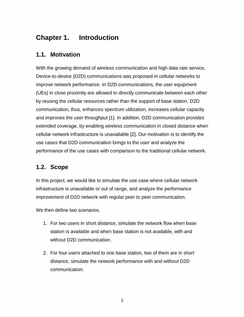
The topology of this simulation scenario includes three nodes, two UEs to
represent user1 and user2, and one eNodeB to represent the base station.
In the traditional cellular network, we connect user1 and user2 to eNodeB
respectively. However, user1 and user2 have no direct connection with each
other.
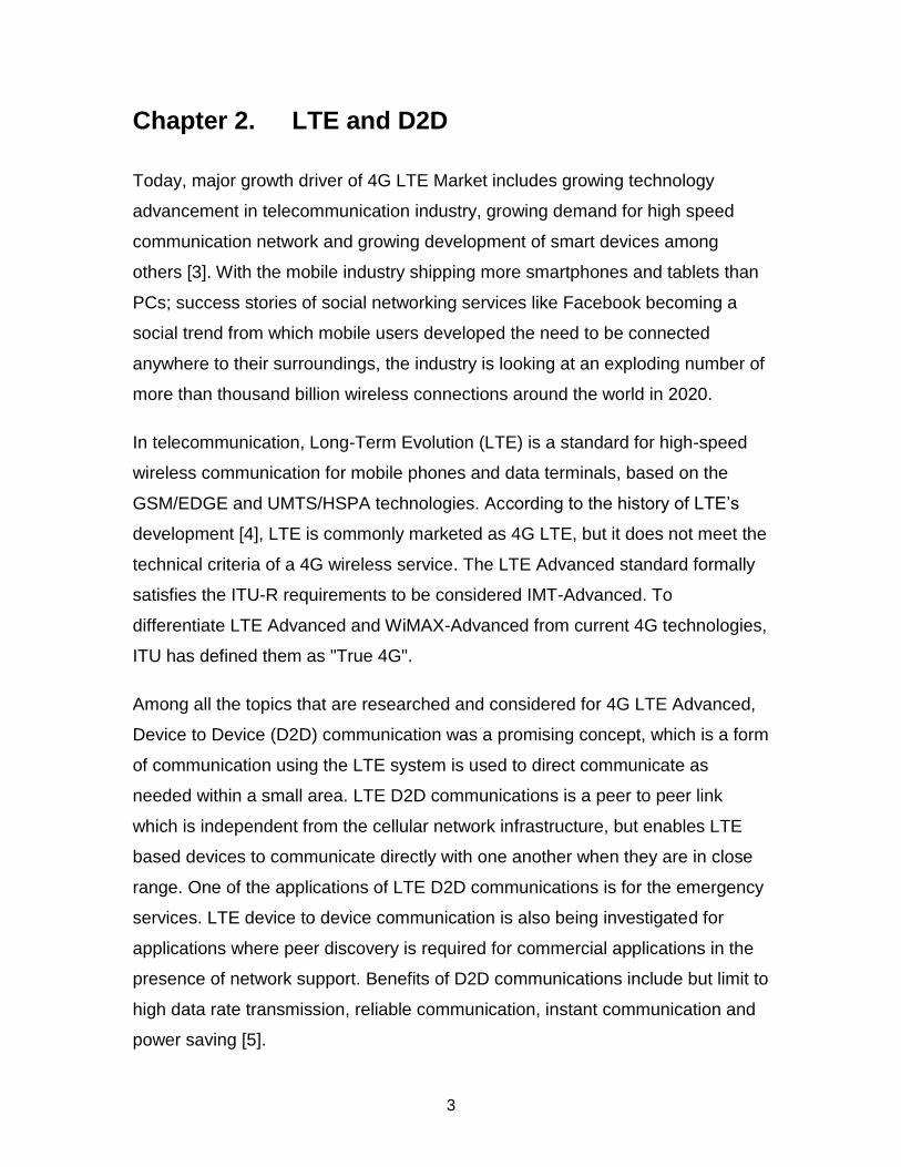
With D2D communication enabled, user1 and user2 have the ability to connect to
the base station. In addition, the direct communication between user1 and user2
is enabled.
Figures shown below display the traditional cellular network topology and D2D
communication network topology.
5
Figure 2 Topology of Base Station Unavailable scenario simulation without D2D communication (using NetAnim)
Figure 3 Topology of Base Station Unavailable scenario simulation with D2D communication (using NetAnim)

6
Workflow
This simulation start with communication between user1 and user2, i.e. user1
sends packets to user2 and user2 send packets to user1. Then after 5s time, the
service of base station becomes unavailable.
Figure 4 Process of Base Station Unavailable scenario simulation without D2D communication
Figure 5 Process of Base Station Unavailable scenario simulation with D2D communication
Attributes
We set the attributes value based on LTE standard. The normal propagation
delay between a user equipment and base station is 2ms, the data rate 50Mbps
is a 20MHz channel is used. The maximum transmission unit of 1428 is standard
7
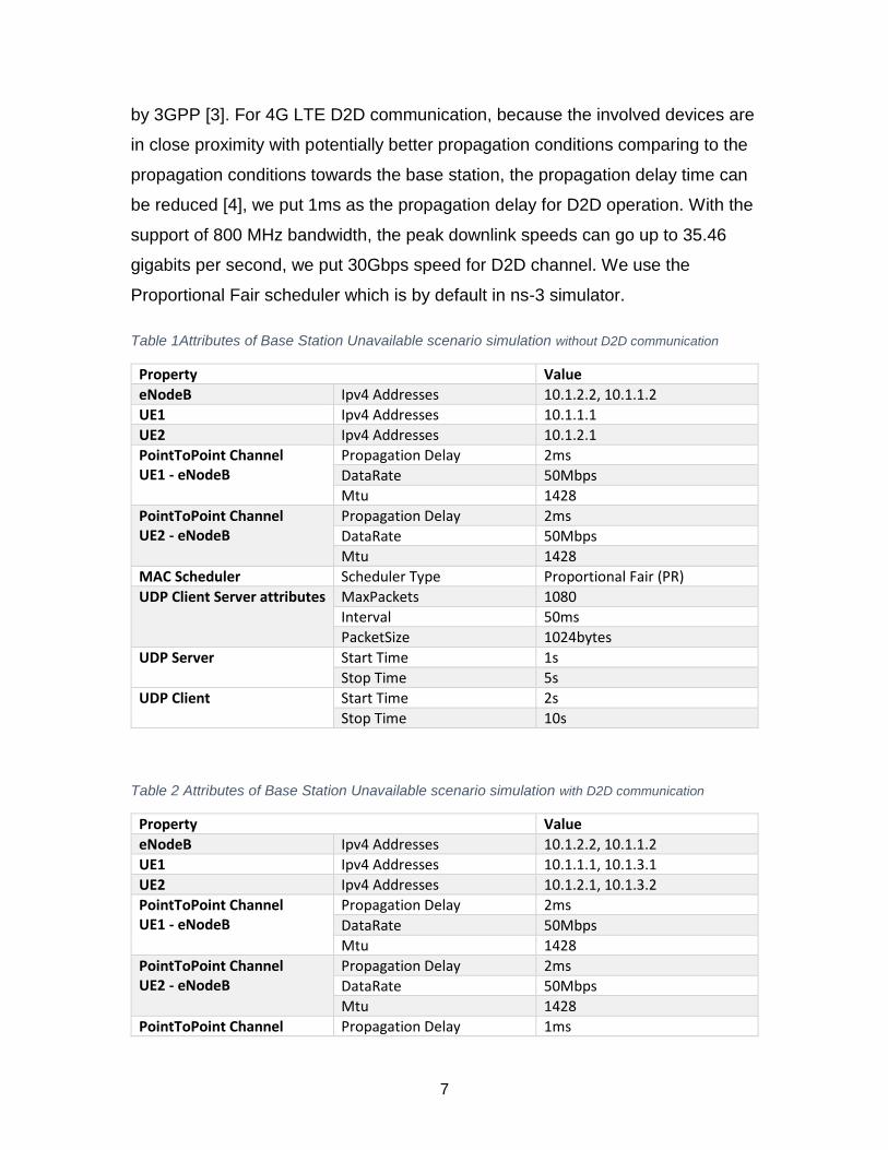
by 3GPP [3]. For 4G LTE D2D communication, because the involved devices are
in close proximity with potentially better propagation conditions comparing to the
propagation conditions towards the base station, the propagation delay time can
be reduced [4], we put 1ms as the propagation delay for D2D operation. With the
support of 800 MHz bandwidth, the peak downlink speeds can go up to 35.46
gigabits per second, we put 30Gbps speed for D2D channel. We use the
Proportional Fair scheduler which is by default in ns-3 simulator.
Table 1Attributes of Base Station Unavailable scenario simulation without D2D communication
Property Value
eNodeB Ipv4 Addresses 10.1.2.2, 10.1.1.2
UE1 Ipv4 Addresses 10.1.1.1
UE2 Ipv4 Addresses 10.1.2.1
PointToPoint Channel UE1 - eNodeB
Propagation Delay 2ms
DataRate 50Mbps
Mtu 1428
PointToPoint Channel UE2 - eNodeB
Propagation Delay 2ms
DataRate 50Mbps
Mtu 1428
MAC Scheduler Scheduler Type Proportional Fair (PR)
UDP Client Server attributes MaxPackets 1080
Interval 50ms
PacketSize 1024bytes
UDP Server Start Time 1s
Stop Time 5s
UDP Client Start Time 2s
Stop Time 10s
Table 2 Attributes of Base Station Unavailable scenario simulation with D2D communication
Property Value
eNodeB Ipv4 Addresses 10.1.2.2, 10.1.1.2
UE1 Ipv4 Addresses 10.1.1.1, 10.1.3.1
UE2 Ipv4 Addresses 10.1.2.1, 10.1.3.2
PointToPoint Channel UE1 - eNodeB
Propagation Delay 2ms
DataRate 50Mbps
Mtu 1428
PointToPoint Channel UE2 - eNodeB
Propagation Delay 2ms
DataRate 50Mbps
Mtu 1428
PointToPoint Channel Propagation Delay 1ms

8
UE1 - UE2 DataRate 30Gbps
Mtu 1428
MAC Scheduler Scheduler Type Proportional Fair (PR)
UDP Client Server attributes MaxPackets 1080
Interval 50ms
PacketSize 1024bytes
UDP Server Start Time 1s
Stop Time 5s
UDP Client Start Time 2s
Stop Time 10s
3.1.2. Simulation High Volume Traffic
In this simulation scenario, we will simulate the wireless communication of four
users, user1, user2, user3 and user4 are all attached to a base station, with the
condition of user1 and user2 are in close distance (10 meters). We setup
communication between user1 and user2, user3 and user2, and user4 and
user2. Then we simulate the received packet, delay time and throughput at user2
for both traditional network situation and D2D network situation.
Topology
The topology of this simulation scenario includes five nodes, four UEs to
represent user1, user2, user3, and user4, and one eNodeB to represent the base
station.
In the traditional cellular network, we connect all users to eNodeB. However,
none of the users have direct connection with others.
With D2D communication enabled, in addition to all users have connection to
base station, the direct communication between user1 and user2 is enabled.
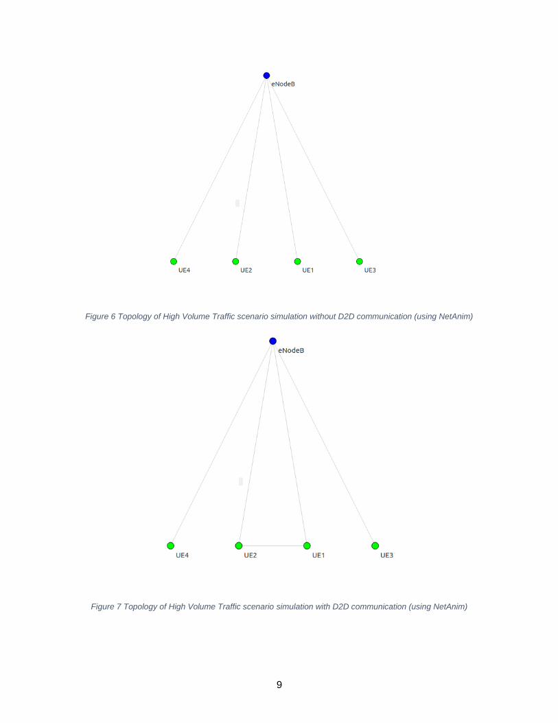
Figures shown below display the traditional cellular network topology and D2D
communication network topology.
9
Figure 6 Topology of High Volume Traffic scenario simulation without D2D communication (using NetAnim)
Figure 7 Topology of High Volume Traffic scenario simulation with D2D communication (using NetAnim)

10
Workflow
This simulation enables the communication between user2 and other users, i.e.
user2 communicates with user1, user3 and user4. We implement two situations,
one is the traditional cellular network, all communications have to go through
base station, the other one is D2D network, user1 and user2 are able to directly
communicate with each other, and other users’ communication with user2
through base station.
The figure below shows the network flow between the UEs.
Figure 8 Network flow of High Volume Traffic scenario simulation without D2D communication (using PhyViz)
Figure 9 Network flow of High Volume Traffic scenario simulation with D2D communication (using PhyViz)

11
Attributes
We use the same attribute values as the base station unavailable scenario for
PointToPoint Channel, MAC Scheduler, UDP Client attributes.
The table of attribute values are shown in Appendix A.
3.2. Simulation and Results
3.2.1. Simulation Base Station Unavailable
In this scenario, we would like to show when base station is unavailable to users,
the users in close proximity will still have communication service with D2D
communication enabled.
We first adopt simulation time 10s with the attributes setting shown in the
previous section, set the base station unavailable at 5s.
The table below shows one flow of the simulation results given by flow monitor
(simulation time 10s), and the throughput calculated by
𝑇𝑜𝑡𝑎𝑙 𝑅𝑥 𝑏𝑦𝑡𝑒𝑠∗8𝑏𝑖𝑡𝑠/𝑏𝑦𝑡𝑒
𝑇𝑜𝑡𝑎𝑙 𝑡𝑟𝑎𝑛𝑠𝑚𝑖𝑠𝑠𝑖𝑜𝑛 𝑡𝑖𝑚𝑒∗1024∗1024 (𝑀𝑏𝑝𝑠).
Table 3 Simulation results of Base Station Unavailable scenario simulation without D2D
communication
UDP 10.1.1.1 10.1.2.1
Tx bitrate 171.173 kbps
Rx bitrate 171.173 kbps
Throughput 0.162836 Mbps
Mean delay 7.3728ms
Tx Bytes 63120
Rx Bytes 63120
Tx Packets 60
Rx Packets 60
Time first Rx packet 2.00737e+09ns
Time last Rx packet 4.95737e+09ns
Delay sum 4.42368e+08ns

12
Table 4 Simulation results of Base Station Unavailable scenario simulation with D2D communication
UDP 10.1.3.2 10.1.1.1
Tx bitrate 169.379 kbps
Rx bitrate 169.379 kbps
Throughput 0.161512 Mbps
Mean delay 1.00027ms
Tx Bytes 168320
Rx Bytes 168320
Tx Packets 160
Rx Packets 160
Time first Rx packet 2.001e+09ns
Time last Rx packet 9.951e+09ns
Delay sum 1.60044e+08ns
We than increase the simulation time and compare the received packets and
throughput between the two simulations.
Increasing the simulation time and keep the base station unavailable from 5s, we
draw the following graph for Rx Packets on UE1.
Figure 10 Received packet bytes comparison with increasing simulation time Base Station Unavailable scenario
0
100000
200000
300000
400000
500000
600000
700000
10s 15s 20s 25s 30s
Receive Packet Bytes VS simulation time
D2D: Rx Packet Bytes Without D2D: Rx Packet Bytes
13
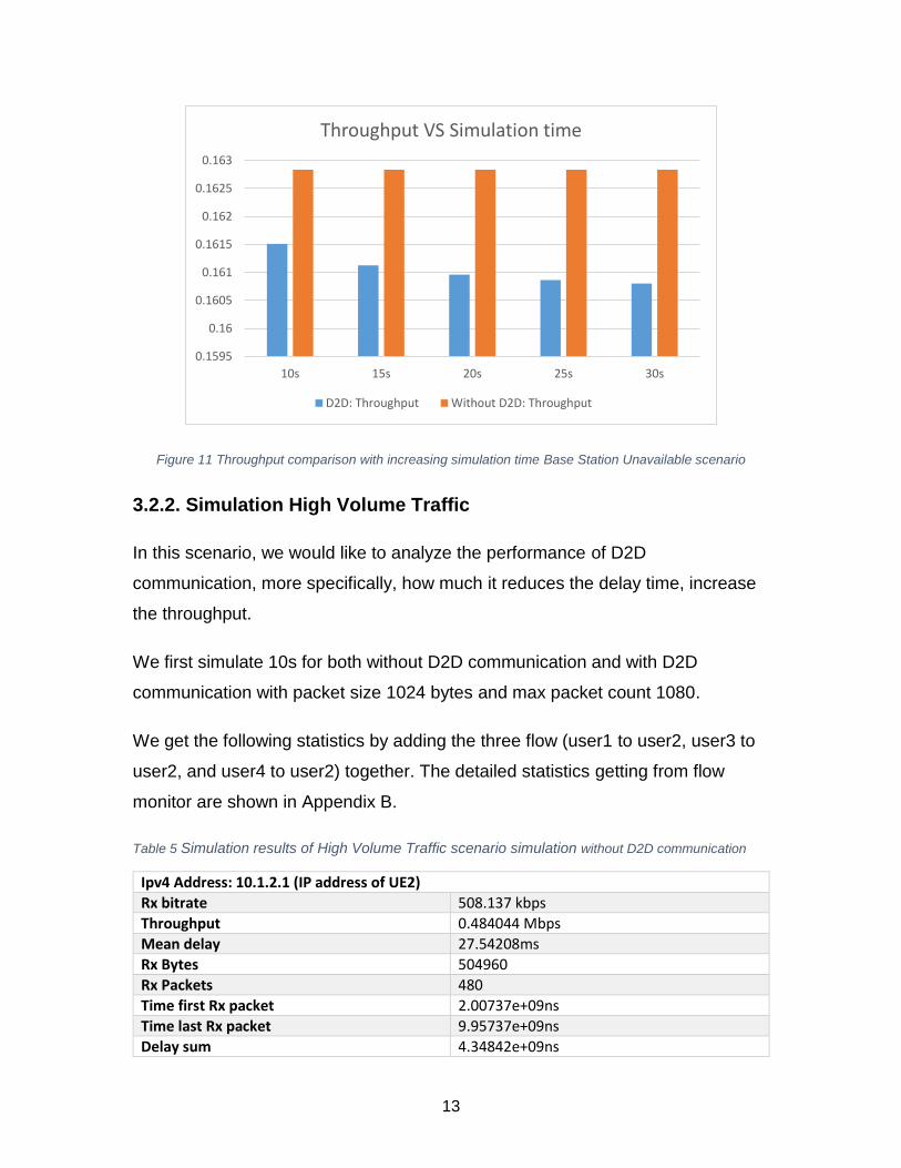
Figure 11 Throughput comparison with increasing simulation time Base Station Unavailable scenario
3.2.2. Simulation High Volume Traffic
In this scenario, we would like to analyze the performance of D2D
communication, more specifically, how much it reduces the delay time, increase
the throughput.
We first simulate 10s for both without D2D communication and with D2D
communication with packet size 1024 bytes and max packet count 1080.
We get the following statistics by adding the three flow (user1 to user2, user3 to
user2, and user4 to user2) together. The detailed statistics getting from flow
monitor are shown in Appendix B.
Table 5 Simulation results of High Volume Traffic scenario simulation without D2D communication
Ipv4 Address: 10.1.2.1 (IP address of UE2)
Rx bitrate 508.137 kbps
Throughput 0.484044 Mbps
Mean delay 27.54208ms
Rx Bytes 504960
Rx Packets 480
Time first Rx packet 2.00737e+09ns
Time last Rx packet 9.95737e+09ns
Delay sum 4.34842e+09ns
0.1595
0.16
0.1605
0.161
0.1615
0.162
0.1625
0.163
10s 15s 20s 25s 30s
Throughput VS Simulation time
D2D: Throughput Without D2D: Throughput

14
Table 6 Simulation results of High Volume Traffic scenario simulation with D2D communication
Ipv4 Address: 10.1.2.1 (IP address of UE2)
Rx bitrate 508.137 kbps
Throughput 0.484242 Mbps
Mean delay 17.43227ms
Rx Bytes 504960
Rx Packets 480
Time first Rx packet 2.001e+09ns
Time last Rx packet 9.951e+09ns
Delay sum 2.789164e+09ns
We than increase the simulation time and packet size 1024 bytes and max
packet count 1080, compare the delay time, transmit and receive rate,
throughput between the two simulations.
The statistics is in Appendix C.
Figure 12 Received packet bytes comparison with increasing simulation time of High volume traffic scenario
0
200000
400000
600000
800000
1000000
1200000
1400000
1600000
1800000
2000000
10s 15s 20s 25s 30s
Rx Packet Bytes VS Simulation Time
D2D: Rx Packet Bytes Without D2D: Rx Packet Bytes
15
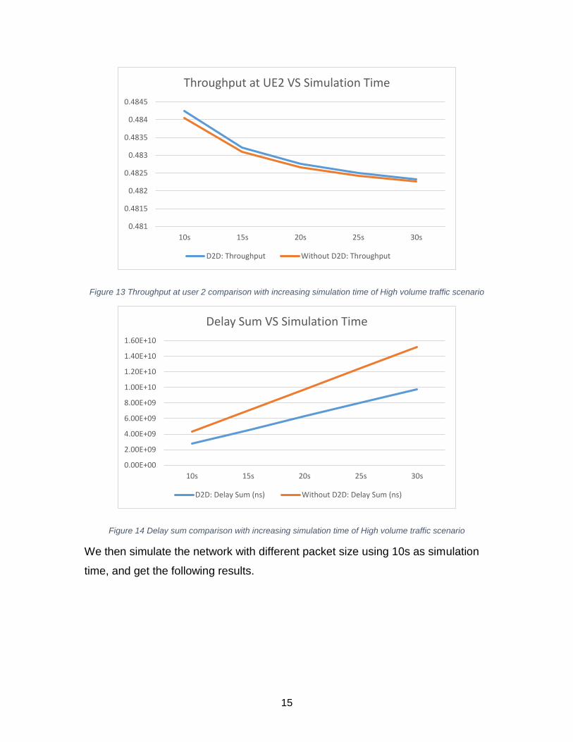
Figure 13 Throughput at user 2 comparison with increasing simulation time of High volume traffic scenario
Figure 14 Delay sum comparison with increasing simulation time of High volume traffic scenario
We then simulate the network with different packet size using 10s as simulation
time, and get the following results.
0.481
0.4815
0.482
0.4825
0.483
0.4835
0.484
0.4845
10s 15s 20s 25s 30s
Throughput at UE2 VS Simulation Time
D2D: Throughput Without D2D: Throughput
0.00E+00
2.00E+09
4.00E+09
6.00E+09
8.00E+09
1.00E+10
1.20E+10
1.40E+10
1.60E+10
10s 15s 20s 25s 30s
Delay Sum VS Simulation Time
D2D: Delay Sum (ns) Without D2D: Delay Sum (ns)
16
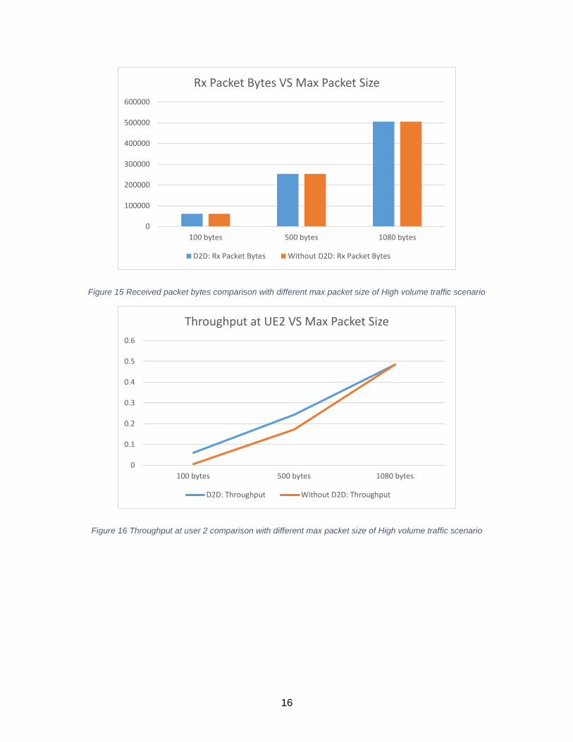
Figure 15 Received packet bytes comparison with different max packet size of High volume traffic scenario
Figure 16 Throughput at user 2 comparison with different max packet size of High volume traffic scenario
0
100000
200000
300000
400000
500000
600000
100 bytes 500 bytes 1080 bytes
Rx Packet Bytes VS Max Packet Size
D2D: Rx Packet Bytes Without D2D: Rx Packet Bytes
0
0.1
0.2
0.3
0.4
0.5
0.6
100 bytes 500 bytes 1080 bytes
Throughput at UE2 VS Max Packet Size
D2D: Throughput Without D2D: Throughput
17
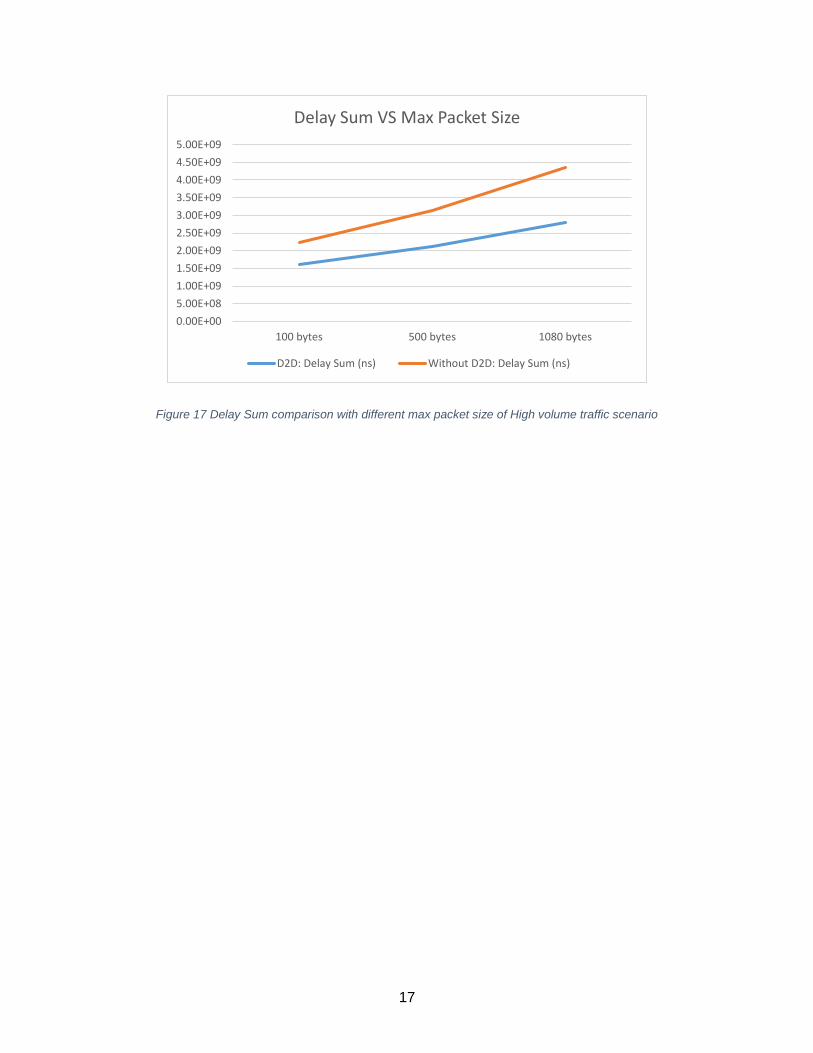
Figure 17 Delay Sum comparison with different max packet size of High volume traffic scenario
0.00E+00
5.00E+08
1.00E+09
1.50E+09
2.00E+09
2.50E+09
3.00E+09
3.50E+09
4.00E+09
4.50E+09
5.00E+09
100 bytes 500 bytes 1080 bytes
Delay Sum VS Max Packet Size
D2D: Delay Sum (ns) Without D2D: Delay Sum (ns)

18
Chapter 4. Discussion and conclusion
4.1. Base Station Unavailable Scenario
In this scenario, we disable the base station at 5 seconds, and increasing the
simulation time. From the graph shown in section 3.2.1 we can see that when the
base station is available and there are only two users, the received packets are
of the same. When the base station is not available, the user stop receiving
packets without D2D communication enabled. However, with D2D
communication, user continues receive packets. With simulation time of 10s, the
packet lost rate of cellular network without D2D enabled is 168320−63120
168320= 62.5%.
When the simulation time lasts to 30 seconds, the packet lost rate of cellular
network without D2D enabled is increased to 589120−63120
589120= 89.26%.
With this simulation, we conclude that D2D communication can reduce the
dependency on the cellular network infrastructure, and it is useful when any
disasters happen.
4.2. High Volume Traffic Scenario
In this scenario, we compare the simulation results of D2D communication
enabled and not enabled. From the graphs shown in section 3.2.2 we can see
that received packets are the same for traditional network and D2D network
(without adding the effect of packet loss). Propagation delay of routing through
base station is larger then D2D communication, the difference is increasing over
simulation time. For simulation time is 10s, the difference between two delay sum
is 4.35 − 2.79 = 1.56𝑠, and it goes up to 15.2 − 9.76 = 5.44𝑠 when simulates for
30s. The throughput of D2D communication is slightly larger by about 0.04% than
the traditional network when simulating 10 seconds. With increasing packet size,
we notice that the delay is getting larger.
19
From this simulation, we see that D2D communication is capable of enhancing
network performance by reducing communication delay, increasing throughput
[5].The use case of D2D communications are multimedia downloading, video
streaming, peer-to-peer file sharing, etc.
4.3. Conclusions
Device-to-device (D2D) communications is considered as new paradigm to
provide high performance in cellular network, improving coverage, high data
rates, and enabling applications such as video streaming, and file sharing.
In this project, we evaluate the different use cases where D2D communications
provides enhanced network communication experience. We simulate the
scenarios using NS-3 simulator, present the matrix and discuss the conclusions.
4.4. Challenges and Future work
The main challenge to this project is to get familiar with NS-3 simulator within a
tight timeline. We attempted to find existing library of D2D implementation using
NS-3, but we did not find a feasible one. Fortunately, with the documentation and
google community group, we are able to implement the project ourselves.
In our future work, we will make the simulation scalable to many user equipment
and multiple base stations. We will also consider more factors to make the
simulation close to the real network case, such as spectrum utilization, D2D
device discovery, base station hand over effect.
20
References
[1] E.SREE HARSHA1, T. TIRUPAL2 “LTE-Advanced Cellular Networks for D2D
Communications” International Journal of Scientific Engineering and Technology
Research Volume.03, IssueNo.18, August-2014.
[2] Xuemin Shen “Device-to-Device Communication in 5G Cellular Networks” IEEE
Network March/April 2015.
[3]"4G LTE Market Analysis, Market Size,Analysis, Regional Outlook, Competitive
Strategies and Forecasts, 2016 To 2027", EIN Presswire, 2017. [Online]. Available:
https://www.einpresswire.com/article/339113397/4g-lte-market-analysis-market-size-
analysis-regional-outlook-competitive-strategies-and-forecasts-2016-to-2027. [Accessed:
15- Apr- 2017].
[4]"LTE (telecommunication)", En.wikipedia.org, 2017. [Online]. Available:
https://en.wikipedia.org/wiki/LTE_(telecommunication). [Accessed: 15- Apr- 2017].
[5]"4G LTE D2D | Device to Device Communication | Radio-Electronics.Com", Radio-
electronics.com, 2017. [Online]. Available: http://www.radio-
electronics.com/info/cellulartelecomms/lte-long-term-evolution/4g-lte-advanced-d2d-
device-to-device.php. [Accessed: 15- Apr- 2017].
[6] "3GPP specification CRs: 29.281", 3gpp.org, 2017. [Online]. Available:
http://www.3gpp.org/DynaReport/29281-CRs.htm. [Accessed: 15- Apr- 2017].
[7] A. Osseiran, 5G mobile and wireless communications technology, 1st ed. United
Kingdom: Cambridge University Press, 2016.
[8] Arash Asadi ,Qing Wang, , and Vincenzo Mancuso,” A Survey on Device-to-Device
Communication in Cellular Networks” arXiv:1310.0720v6 [cs.GT] 29 Apr 2014.

21
Appendix
A. Attribute Settings
Table 7 Attributes of High Volume Traffic scenario simulation without D2D communication
Property Value
eNodeB Ipv4 Addresses 10.1.2.2, 10.1.1.2, 10.1.4.2, 10.1.5.2
UE1 Ipv4 Addresses 10.1.1.1, 10.1.3.1
UE2 Ipv4 Addresses 10.1.2.1, 10.1.3.2
UE3 Ipv4 Addresses 10.1.4.1
UE4 Ipv4 Addresses 10.1.5.1
PointToPoint Channel UE1 - eNodeB
Propagation Delay 2ms
DataRate 50Mbps
Mtu 1428
PointToPoint Channel UE2 - eNodeB
Propagation Delay 2ms
DataRate 50Mbps
Mtu 1428
PointToPoint Channel UE3 - eNodeB
Propagation Delay 2ms
DataRate 50Mbps
Mtu 1428
PointToPoint Channel UE4 - eNodeB
Propagation Delay 2ms
DataRate 50Mbps
Mtu 1428
MAC Scheduler Scheduler Type Proportional Fair (PR)
UDP Client Server attributes MaxPackets 1080
Interval 50ms
PacketSize 1024bytes
UDP Server Start Time 1s
Stop Time 10s
UDP Client Start Time 2s
Stop Time 10s
Table 8 Attributes of High Volume Traffic scenario simulation with D2D communication
Property Value
eNodeB Ipv4 Addresses 10.1.2.2, 10.1.1.2, 10.1.4.2, 10.1.5.2
UE1 Ipv4 Addresses 10.1.1.1, 10.1.3.1
UE2 Ipv4 Addresses 10.1.2.1, 10.1.3.2
UE3 Ipv4 Addresses 10.1.4.1
UE4 Ipv4 Addresses 10.1.5.1
PointToPoint Channel Propagation Delay 2ms
22
UE1 - eNodeB DataRate 50Mbps
Mtu 1428
PointToPoint Channel UE2 - eNodeB
Propagation Delay 2ms
DataRate 50Mbps
Mtu 1428
PointToPoint Channel UE3 - eNodeB
Propagation Delay 2ms
DataRate 50Mbps
Mtu 1428
PointToPoint Channel UE4 - eNodeB
Propagation Delay 2ms
DataRate 50Mbps
Mtu 1428
PointToPoint Channel UE1 - UE2
Propagation Delay 1ms
DataRate 30Gbps
Mtu 1428
MAC Scheduler Scheduler Type Proportional Fair (PR)
UDP Client Server attributes MaxPackets 1080
Interval 50ms
PacketSize 1024bytes
UDP Server Start Time 1s
Stop Time 10s
UDP Client Start Time 2s
Stop Time 10s
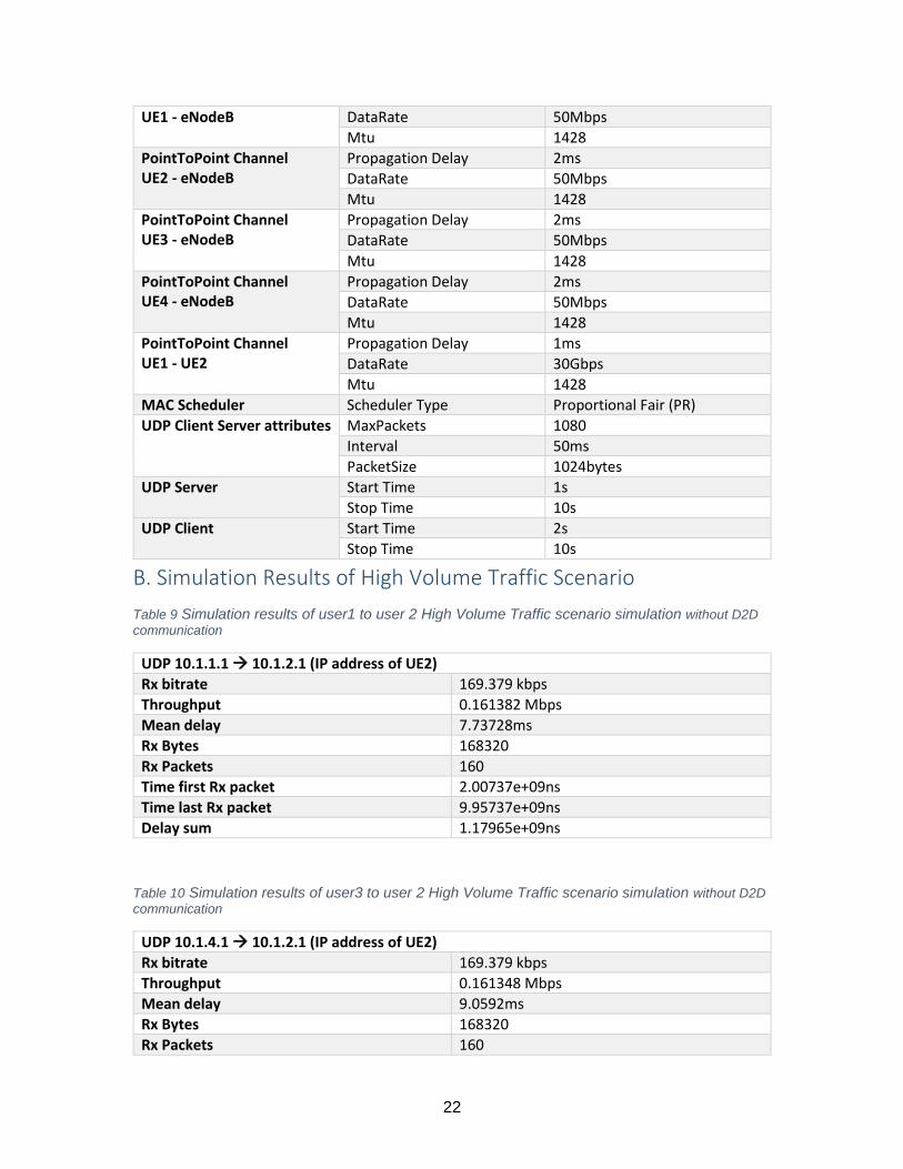
B. Simulation Results of High Volume Traffic Scenario
Table 9 Simulation results of user1 to user 2 High Volume Traffic scenario simulation without D2D
communication
UDP 10.1.1.1 10.1.2.1 (IP address of UE2)
Rx bitrate 169.379 kbps
Throughput 0.161382 Mbps
Mean delay 7.73728ms
Rx Bytes 168320
Rx Packets 160
Time first Rx packet 2.00737e+09ns
Time last Rx packet 9.95737e+09ns
Delay sum 1.17965e+09ns
Table 10 Simulation results of user3 to user 2 High Volume Traffic scenario simulation without D2D
communication
UDP 10.1.4.1 10.1.2.1 (IP address of UE2)
Rx bitrate 169.379 kbps
Throughput 0.161348 Mbps
Mean delay 9.0592ms
Rx Bytes 168320
Rx Packets 160
23
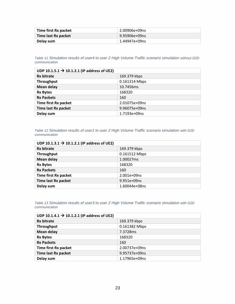
Time first Rx packet 2.00906e+09ns
Time last Rx packet 9.95906e+09ns
Delay sum 1.44947e+09ns
Table 11 Simulation results of user4 to user 2 High Volume Traffic scenario simulation without D2D
communication
UDP 10.1.5.1 10.1.2.1 (IP address of UE2)
Rx bitrate 169.379 kbps
Throughput 0.161314 Mbps
Mean delay 10.7456ms
Rx Bytes 168320
Rx Packets 160
Time first Rx packet 2.01075e+09ns
Time last Rx packet 9.96075e+09ns
Delay sum 1.7193e+09ns
Table 12 Simulation results of user1 to user 2 High Volume Traffic scenario simulation with D2D
communication
UDP 10.1.3.1 10.1.2.1 (IP address of UE2)
Rx bitrate 169.379 kbps
Throughput 0.161512 Mbps
Mean delay 1.00027ms
Rx Bytes 168320
Rx Packets 160
Time first Rx packet 2.001e+09ns
Time last Rx packet 9.951e+09ns
Delay sum 1.60044e+08ns
Table 13 Simulation results of user3 to user 2 High Volume Traffic scenario simulation with D2D
communication
UDP 10.1.4.1 10.1.2.1 (IP address of UE2)
Rx bitrate 169.379 kbps
Throughput 0.161382 Mbps
Mean delay 7.3728ms
Rx Bytes 168320
Rx Packets 160
Time first Rx packet 2.00737e+09ns
Time last Rx packet 9.95737e+09ns
Delay sum 1.17965e+09ns
24
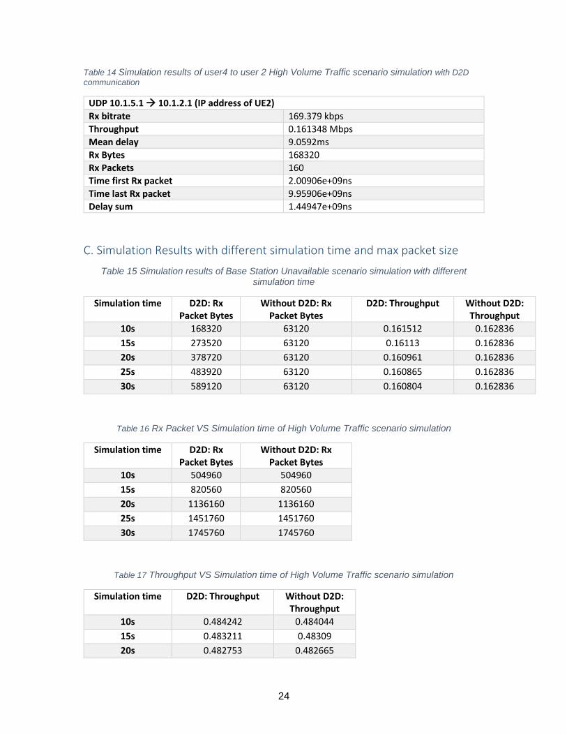
Table 14 Simulation results of user4 to user 2 High Volume Traffic scenario simulation with D2D
communication
UDP 10.1.5.1 10.1.2.1 (IP address of UE2)
Rx bitrate 169.379 kbps
Throughput 0.161348 Mbps
Mean delay 9.0592ms
Rx Bytes 168320
Rx Packets 160
Time first Rx packet 2.00906e+09ns
Time last Rx packet 9.95906e+09ns
Delay sum 1.44947e+09ns
C. Simulation Results with different simulation time and max packet size
Table 15 Simulation results of Base Station Unavailable scenario simulation with different simulation time
Simulation time D2D: Rx Packet Bytes
Without D2D: Rx Packet Bytes
D2D: Throughput Without D2D: Throughput
10s 168320 63120 0.161512 0.162836
15s 273520 63120 0.16113 0.162836
20s 378720 63120 0.160961 0.162836
25s 483920 63120 0.160865 0.162836
30s 589120 63120 0.160804 0.162836
Table 16 Rx Packet VS Simulation time of High Volume Traffic scenario simulation
Simulation time D2D: Rx Packet Bytes
Without D2D: Rx Packet Bytes
10s 504960 504960
15s 820560 820560
20s 1136160 1136160
25s 1451760 1451760
30s 1745760 1745760
Table 17 Throughput VS Simulation time of High Volume Traffic scenario simulation
Simulation time D2D: Throughput Without D2D: Throughput
10s 0.484242 0.484044
15s 0.483211 0.48309
20s 0.482753 0.482665
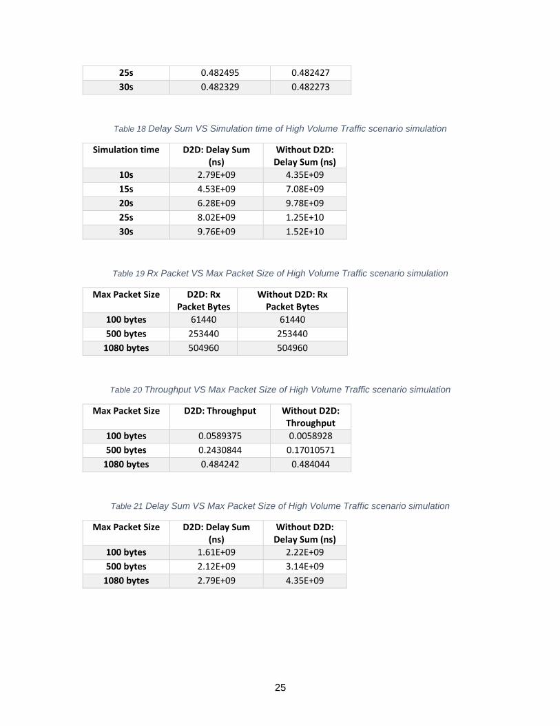
25
25s 0.482495 0.482427
30s 0.482329 0.482273
Table 18 Delay Sum VS Simulation time of High Volume Traffic scenario simulation
Simulation time D2D: Delay Sum (ns)
Without D2D: Delay Sum (ns)
10s 2.79E+09 4.35E+09
15s 4.53E+09 7.08E+09
20s 6.28E+09 9.78E+09
25s 8.02E+09 1.25E+10
30s 9.76E+09 1.52E+10
Table 19 Rx Packet VS Max Packet Size of High Volume Traffic scenario simulation
Max Packet Size D2D: Rx Packet Bytes
Without D2D: Rx Packet Bytes
100 bytes 61440 61440
500 bytes 253440 253440
1080 bytes 504960 504960
Table 20 Throughput VS Max Packet Size of High Volume Traffic scenario simulation
Max Packet Size D2D: Throughput Without D2D: Throughput
100 bytes 0.0589375 0.0058928
500 bytes 0.2430844 0.17010571
1080 bytes 0.484242 0.484044
Table 21 Delay Sum VS Max Packet Size of High Volume Traffic scenario simulation
Max Packet Size D2D: Delay Sum (ns)
Without D2D: Delay Sum (ns)
100 bytes 1.61E+09 2.22E+09
500 bytes 2.12E+09 3.14E+09
1080 bytes 2.79E+09 4.35E+09
26
D. NS-3 Code
#include <fstream> #include "ns3/core-module.h" #include "ns3/point-to-point-module.h" #include "ns3/applications-module.h" #include "ns3/internet-module.h" #include "ns3/mobility-module.h" #include "ns3/lte-module.h" #include "ns3/lte-helper.h" #include "ns3/epc-helper.h" #include "ns3/ipv4-global-routing-helper.h" #include "ns3/flow-monitor-module.h" #include "ns3/netanim-module.h" #include <ns3/buildings-helper.h> using namespace ns3; NS_LOG_COMPONENT_DEFINE ("d2dproject"); int main (int argc, char *argv[]) { double lat = 2.0; // Latency uint64_t rate = 5000000; // Data rate in bps double interval = 0.05; double simulation_time = 10.0; // in seconds CommandLine cmd; cmd.AddValue ("latency", "P2P link Latency in miliseconds", lat); cmd.AddValue ("rate", "P2P data rate in bps", rate); cmd.AddValue ("interval", "UDP client packet interval", interval); cmd.Parse (argc, argv); // Enable logging for UdpClient and UdpServer // LogComponentEnable ("UdpClient", LOG_LEVEL_INFO); // LogComponentEnable ("UdpServer", LOG_LEVEL_INFO); // Create nodes required by the topology (shown in the paper). Ptr<LteHelper> lteHelper = CreateObject<LteHelper> (); NS_LOG_INFO ("Create nodes."); NodeContainer enbNodes; NodeContainer ueNodes; enbNodes.Create (1); ueNodes.Create (4); // Install Mobility Model Ptr<ListPositionAllocator> positions = CreateObject<ListPositionAllocator> (); positions->Add (Vector (10, 10, 0)); positions->Add (Vector (0, 10, 0));

27
positions->Add (Vector (20, 10, 0)); positions->Add (Vector (-10, 10, 0)); MobilityHelper mobility; mobility.SetMobilityModel("ns3::ConstantPositionMobilityModel"); mobility.SetPositionAllocator(positions); mobility.Install(ueNodes); BuildingsHelper::Install (ueNodes); mobility.SetMobilityModel("ns3::ConstantPositionMobilityModel"); Ptr<ListPositionAllocator> position_enb = CreateObject<ListPositionAllocator> (); position_enb->Add (Vector (5, -20, 0)); mobility.SetPositionAllocator(position_enb); mobility.Install(enbNodes); BuildingsHelper::Install (enbNodes); // Create Devices and install them in the Nodes (eNB and UE) NetDeviceContainer enbDevs; NetDeviceContainer ueDevOne; NetDeviceContainer ueDevTwo; NetDeviceContainer ueDevThree; NetDeviceContainer ueDevFour; // Default scheduler is PF, uncomment to use RR //lteHelper->SetSchedulerType ("ns3::RrFfMacScheduler"); enbDevs = lteHelper->InstallEnbDevice (enbNodes); ueDevOne = lteHelper->InstallUeDevice (ueNodes.Get(0)); ueDevTwo = lteHelper->InstallUeDevice (ueNodes.Get(1)); ueDevThree = lteHelper->InstallUeDevice (ueNodes.Get(2)); ueDevFour = lteHelper->InstallUeDevice (ueNodes.Get(3)); // Attach a UE to a eNB lteHelper->Attach (ueDevOne, enbDevs.Get (0)); lteHelper->Attach (ueDevTwo, enbDevs.Get (0)); lteHelper->Attach (ueDevThree, enbDevs.Get (0)); lteHelper->Attach (ueDevFour, enbDevs.Get (0)); NS_LOG_INFO ("Create channels."); // Create the channels required by the topology (shown in the paper). PointToPointHelper p2p; p2p.SetChannelAttribute ("Delay", TimeValue (MilliSeconds (lat))); p2p.SetDeviceAttribute ("DataRate", DataRateValue (DataRate (rate))); p2p.SetDeviceAttribute ("Mtu", UintegerValue (1400)); NetDeviceContainer dev = p2p.Install (ueNodes.Get(0), enbNodes.Get(0)); NetDeviceContainer dev2 = p2p.Install (ueNodes.Get(1), enbNodes.Get(0)); NetDeviceContainer dev3 = p2p.Install (ueNodes.Get(2), enbNodes.Get(0)); NetDeviceContainer dev4 = p2p.Install (ueNodes.Get(3), enbNodes.Get(0)); double d2d_lat = 1.0; uint64_t d2d_rate = 30720000000; // Data rate in bps

28
p2p.SetChannelAttribute ("Delay", TimeValue (MilliSeconds (d2d_lat))); p2p.SetDeviceAttribute ("DataRate", DataRateValue (DataRate (d2d_rate))); p2p.SetDeviceAttribute ("Mtu", UintegerValue (1428)); NetDeviceContainer dev5 = p2p.Install (ueNodes.Get(0), ueNodes.Get(1)); // Add IP addresses. // Install Internet Stack InternetStackHelper internet; internet.Install (ueNodes); internet.Install (enbNodes); Ipv4AddressHelper ipv4; NS_LOG_INFO ("Assign IP Addresses."); ipv4.SetBase ("10.1.1.0", "255.255.255.0"); Ipv4InterfaceContainer i = ipv4.Assign (dev); ipv4.SetBase ("10.1.2.0", "255.255.255.0"); Ipv4InterfaceContainer i2 = ipv4.Assign (dev2); ipv4.SetBase ("10.1.3.0", "255.255.255.0"); Ipv4InterfaceContainer i5 = ipv4.Assign (dev5); ipv4.SetBase ("10.1.4.0", "255.255.255.0"); Ipv4InterfaceContainer i3 = ipv4.Assign (dev3); ipv4.SetBase ("10.1.5.0", "255.255.255.0"); Ipv4InterfaceContainer i4 = ipv4.Assign (dev4); Ipv4GlobalRoutingHelper::PopulateRoutingTables (); NS_LOG_INFO ("Create Applications."); // Create one udpServer application on node one. uint16_t port1 = 8000; // Need different port numbers to ensure there is no conflict uint16_t port2 = 8001; UdpServerHelper server1 (port1); UdpServerHelper server2 (port2); ApplicationContainer apps1; ApplicationContainer apps2; apps1 = server1.Install (enbNodes.Get(0)); apps2 = server2.Install (enbNodes.Get(0)); apps1.Start (Seconds (1.0)); apps1.Stop (Seconds (simulation_time)); apps2.Start (Seconds (1.0)); apps2.Stop (Seconds (simulation_time)); // Create one UdpClient application to send UDP datagrams from node zero to // node one. uint32_t MaxPacketSize = 500; Time interPacketInterval = Seconds (interval); uint32_t maxPacketCount = 10800; UdpClientHelper client1 (i2.GetAddress (0), port1);
29
UdpClientHelper client2 (i.GetAddress (0), port2); client1.SetAttribute ("MaxPackets", UintegerValue (maxPacketCount)); client1.SetAttribute ("Interval", TimeValue (interPacketInterval)); client1.SetAttribute ("PacketSize", UintegerValue (MaxPacketSize)); client2.SetAttribute ("MaxPackets", UintegerValue (maxPacketCount)); client2.SetAttribute ("Interval", TimeValue (interPacketInterval)); client2.SetAttribute ("PacketSize", UintegerValue (MaxPacketSize)); apps1 = client1.Install (ueNodes.Get(0)); apps2 = client2.Install (ueNodes.Get(1)); apps1.Start (Seconds (2.0)); apps1.Stop (Seconds (simulation_time)); apps2.Start (Seconds (2.0)); apps2.Stop (Seconds (simulation_time)); UdpClientHelper client3 (i2.GetAddress (0), port1); UdpClientHelper client4 (i2.GetAddress (0), port2); client3.SetAttribute ("MaxPackets", UintegerValue (maxPacketCount)); client3.SetAttribute ("Interval", TimeValue (interPacketInterval)); client3.SetAttribute ("PacketSize", UintegerValue (MaxPacketSize)); client4.SetAttribute ("MaxPackets", UintegerValue (maxPacketCount)); client4.SetAttribute ("Interval", TimeValue (interPacketInterval)); client4.SetAttribute ("PacketSize", UintegerValue (MaxPacketSize)); apps1 = client3.Install (ueNodes.Get(2)); apps2 = client4.Install (ueNodes.Get(3)); apps1.Start (Seconds (2.0)); apps1.Stop (Seconds (simulation_time)); apps2.Start (Seconds (2.0)); apps2.Stop (Seconds (simulation_time)); // Tracing AsciiTraceHelper ascii; p2p.EnableAscii(ascii.CreateFileStream ("d2dproject4.tr"), dev); p2p.EnablePcap("d2dproject4", dev, false); // Enable NetAnim, set node color and description AnimationInterface anim ("d2dproject4.xml"); anim.SetStartTime (Seconds(1.0)); anim.SetStopTime (Seconds(simulation_time)); anim.UpdateNodeColor(enbNodes.Get (0), 0, 0, 255); anim.UpdateNodeDescription(enbNodes.Get (0), "eNodeB"); anim.UpdateNodeColor(ueNodes.Get(0), 0, 255, 0); anim.UpdateNodeColor(ueNodes.Get(1), 0, 255, 0); anim.UpdateNodeColor(ueNodes.Get(2), 0, 255, 0); anim.UpdateNodeColor(ueNodes.Get(3), 0, 255, 0); anim.UpdateNodeDescription(ueNodes.Get(0), "UE1");
30
anim.UpdateNodeDescription(ueNodes.Get(1), "UE2"); anim.UpdateNodeDescription(ueNodes.Get(2), "UE3"); anim.UpdateNodeDescription(ueNodes.Get(3), "UE4"); anim.EnablePacketMetadata(true); anim.EnableIpv4RouteTracking("d2dproject4_route.xml",Seconds(0),Seconds(10.0), Seconds(0.5)); // // Calculate Throughput using Flowmonitor // FlowMonitorHelper flowmon; Ptr<FlowMonitor> monitor = flowmon.InstallAll(); // // Now, do the actual simulation. // NS_LOG_INFO ("Run Simulation."); Simulator::Stop (Seconds(simulation_time)); Simulator::Run (); monitor->CheckForLostPackets (); Ptr<Ipv4FlowClassifier> classifier = DynamicCast<Ipv4FlowClassifier> (flowmon.GetClassifier ()); std::map<FlowId, FlowMonitor::FlowStats> stats = monitor->GetFlowStats (); for (std::map<FlowId, FlowMonitor::FlowStats>::const_iterator i = stats.begin (); i != stats.end (); ++i) { Ipv4FlowClassifier::FiveTuple t = classifier->FindFlow (i->first); //if ((t.sourceAddress=="10.1.1.1" && t.destinationAddress == "10.1.2.2")) //{ std::cout << "Flow " << i->first << " (" << t.sourceAddress << " -> " << t.destinationAddress << ")\n"; std::cout << " Tx Bytes: " << i->second.txBytes << "\n"; std::cout << " Rx Bytes: " << i->second.rxBytes << "\n"; std::cout << " Throughput: " << i->second.rxBytes * 8.0 / (i->second.timeLastRxPacket.GetSeconds() - i->second.timeFirstTxPacket.GetSeconds())/1024/1024 << " Mbps\n"; //} } monitor->SerializeToXmlFile("d2dproject4.flowmon", true, true); Simulator::Destroy (); NS_LOG_INFO ("Done."); }