Embed Size (px)
Citation preview
Performance analysis of channel coding in satellite communication
based on VSAT Network and MC-CDMA scheme
Mohammed El jourmi1, Hassan El ghazi
2, Abdellatif Bennis
1, Hassan Ouahmane
3
1Physics Department, Hassan II University, FSBM, Casablanca, Morocco
2Telecommunications Department, INPT, Rabat, Morocco
3Networks and Telecommunications Department, ENSA, El jadida, Morocco
Abstract: - Satellites are an essential part of our daily life, and they have a very large usage ranging from
Search and Rescue Operations to Environmental Monitoring. The widest use of satellites is, however, in
communication systems. Satellites can cover vast areas on the world; therefore, they are the nodes where all
links pass through in a communications network. Many users can access such a network simultaneously while
they are widely separated geographically. The purpose of this paper is to model and analyze a geostationary
satellite communication system with VSATs networks in the uplink case, using Multicarrier CDMA system
(MC-CDMA is a combination of multicarrier modulation scheme and CDMA concepts) and channel coding
mechanisms “Turbo code and Convolutional code”. The envisaged system is examined in Ku band and over
AWGN channel. The simulation results are obtained for each different case. The performance of the system is
given in terms of Bit Error Rate (BER) and Signal to Noise Ratio (SNR). In this study the proposed system
coded with Turbo code can achieve better error rate performance compared to coded VSAT MC-CDMA
system with convolutional code.
Keywords—VSAT Network, Turbo code, Convolutional code, MC-CDMA, Ku band, Satellite communication,
Uplink.
1 Introduction Communication satellites, and especially in
geostationary Earth orbit (GEO), provide an
effective platform to relay radio signals between
points on the ground. The users who employ these
signals enjoy a broad spectrum of
telecommunication services on the ground, at sea,
and in the air. Benefits of satellite communications
should in the 1990's be extended to users in all parts
of the world through the use of smaller, inexpensive
and less sophisticated Earth stations for two way
(voice and data), and one way (video, data) use.
Satellite communications pose a major and serious
problem when that concerns the presence of random
errors on the satellite link and that can significantly
degrades the system performance. For this reason
we used channel coding mechanisms to reduce the
error rate and improve the system performance. The
objective of this paper is to design a satellite ground
segment component for use in telecommunications
and analyze its performance. Therefore, the ground
segment is designed to fit in the description of a
Very Small Aperture Terminal (VSAT), which
requires antenna dimensions less than 1.8 m in
diameter. The designed system has a wide
bandwidth and use MC-CDMA scheme, BPSK
modulation, channel coding (Turbo code and
Convolutional code) over AWGN channel. To be
able to send signals through great distance, the
signals need to be amplified before transmission.
The High Power Amplifier (HPA) of Rapp’s model
which is based on a Solide State Power Amplifier
(SSPA) is used and a low noise amplifier (LNA) is
used to amplify very weak signals captured by an
antenna. In this study, the CDMA encoder uses PN
sequences and Walsh Codes to generate a spread
signal. Each VSAT uses a different PN sequence
and each user in a VSAT uses different Walsh
Codes.
This paper is organized as follows. In Section 2 the
VSAT Network are briefly described with its
configurations. The principle of MC-CDMA scheme
is presented with modeling of proposed system in
Section 3. Section 4 presents the principle of
convolutional coding. The principle of Turbo code
is discussed in Section 5. Characteristics of the HPA
which is used in this study are illustrated in Section
6. In section 7 the link budget and simulation model
WSEAS TRANSACTIONS on COMMUNICATIONSMohammed El Jourmi, Hassan El Ghazi, Abdellatif Bennis, Hassan Ouahmane
E-ISSN: 2224-2864 219 Issue 5, Volume 12, May 2013
are presented. Simulation results are presented in
Section 8, and conclusions are drawn in Section 9.
2 VSAT Network Configurations VSAT stands for Very Small Aperture Terminal and
it is the term that is normally used to refer to several
satellite data communication technologies. The term
VSAT assumes the use of a (very) small diameter
antenna (terminal) to receive and/or transmit radio
signals (data) to/from a satellite [21].
There are two major network configurations viz: the
hub-based star VSAT network, which provides a
"star" type of topology, and the "mesh" network,
which allows connections between any pair of
VSATs.
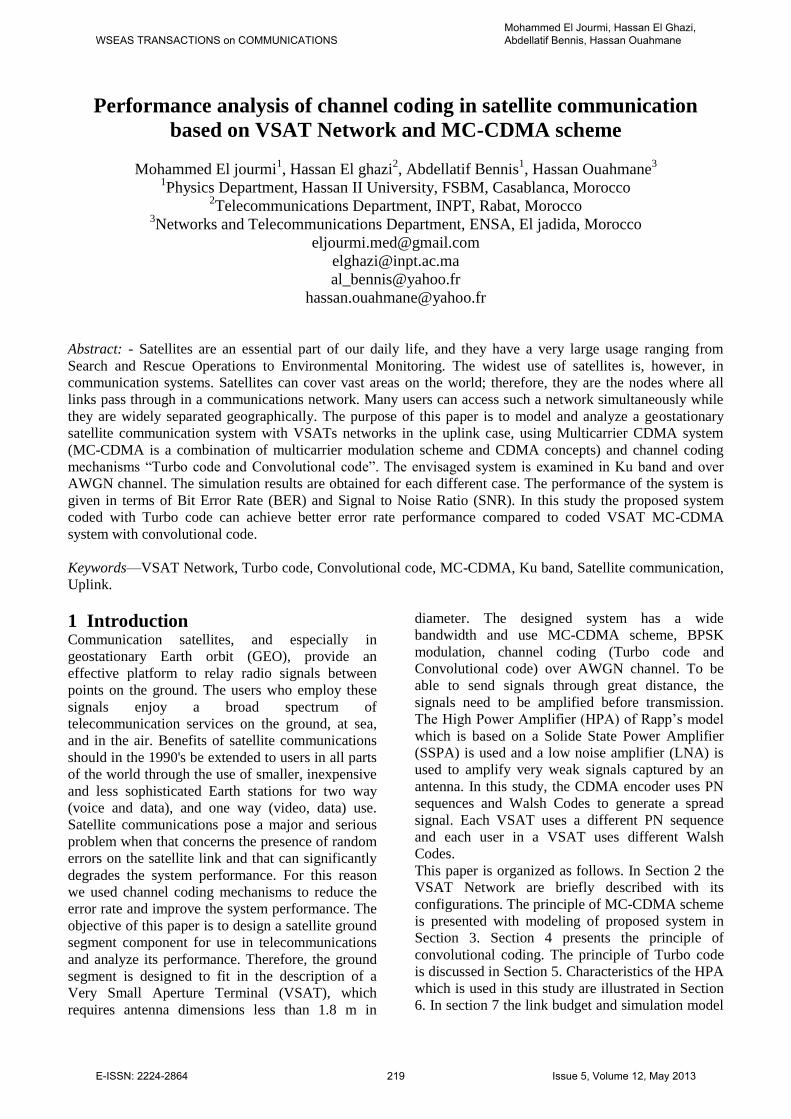
2.1 Meshed VSAT Network As all the VSATs are visible from the satellite,
carriers can be relayed by the satellite from any
VSAT to any other VSAT in the network as shown
in figure 1. This type of configuration is called
point-to-point topology. In this mesh type, earth
stations communicate directly via satellite and will
have only one hop communication. Regarding the
meshed VSAT networks, one must take into account
the following limitations [9]:
Fig 1. Meshed VSAT Network
typically 200 dB carrier power attenuation
on the uplink and the downlink as a result of
the distance to and from a geostationary
satellite;
limited satellite radio frequency power,
typically a few tens of watts;
small size of the VSAT, which limits its
transmitted power and its receiving
sensitivity.
As a result of the above, it can be noticed that the
demodulated signals at the receiving VSAT do not
match the quality requested by the user terminals.
Therefore direct links from VSAT to VSAT may not
be acceptable [13].
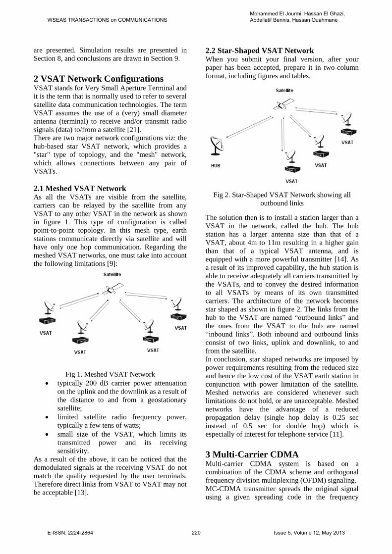
2.2 Star-Shaped VSAT Network When you submit your final version, after your
paper has been accepted, prepare it in two-column
format, including figures and tables.
Fig 2. Star-Shaped VSAT Network showing all
outbound links
The solution then is to install a station larger than a
VSAT in the network, called the hub. The hub
station has a larger antenna size than that of a
VSAT, about 4m to 11m resulting in a higher gain
than that of a typical VSAT antenna, and is
equipped with a more powerful transmitter [14]. As
a result of its improved capability, the hub station is
able to receive adequately all carriers transmitted by
the VSATs, and to convey the desired information
to all VSATs by means of its own transmitted
carriers. The architecture of the network becomes
star shaped as shown in figure 2. The links from the
hub to the VSAT are named “outbound links” and
the ones from the VSAT to the hub are named
“inbound links”. Both inbound and outbound links
consist of two links, uplink and downlink, to and
from the satellite.
In conclusion, star shaped networks are imposed by
power requirements resulting from the reduced size
and hence the low cost of the VSAT earth station in
conjunction with power limitation of the satellite.
Meshed networks are considered whenever such
limitations do not hold, or are unacceptable. Meshed
networks have the advantage of a reduced
propagation delay (single hop delay is 0.25 sec
instead of 0.5 sec for double hop) which is
especially of interest for telephone service [11].
3 Multi-Carrier CDMA Multi-carrier CDMA system is based on a
combination of the CDMA scheme and orthogonal
frequency division multiplexing (OFDM) signaling.
MC-CDMA transmitter spreads the original signal
using a given spreading code in the frequency
WSEAS TRANSACTIONS on COMMUNICATIONSMohammed El Jourmi, Hassan El Ghazi, Abdellatif Bennis, Hassan Ouahmane
E-ISSN: 2224-2864 220 Issue 5, Volume 12, May 2013
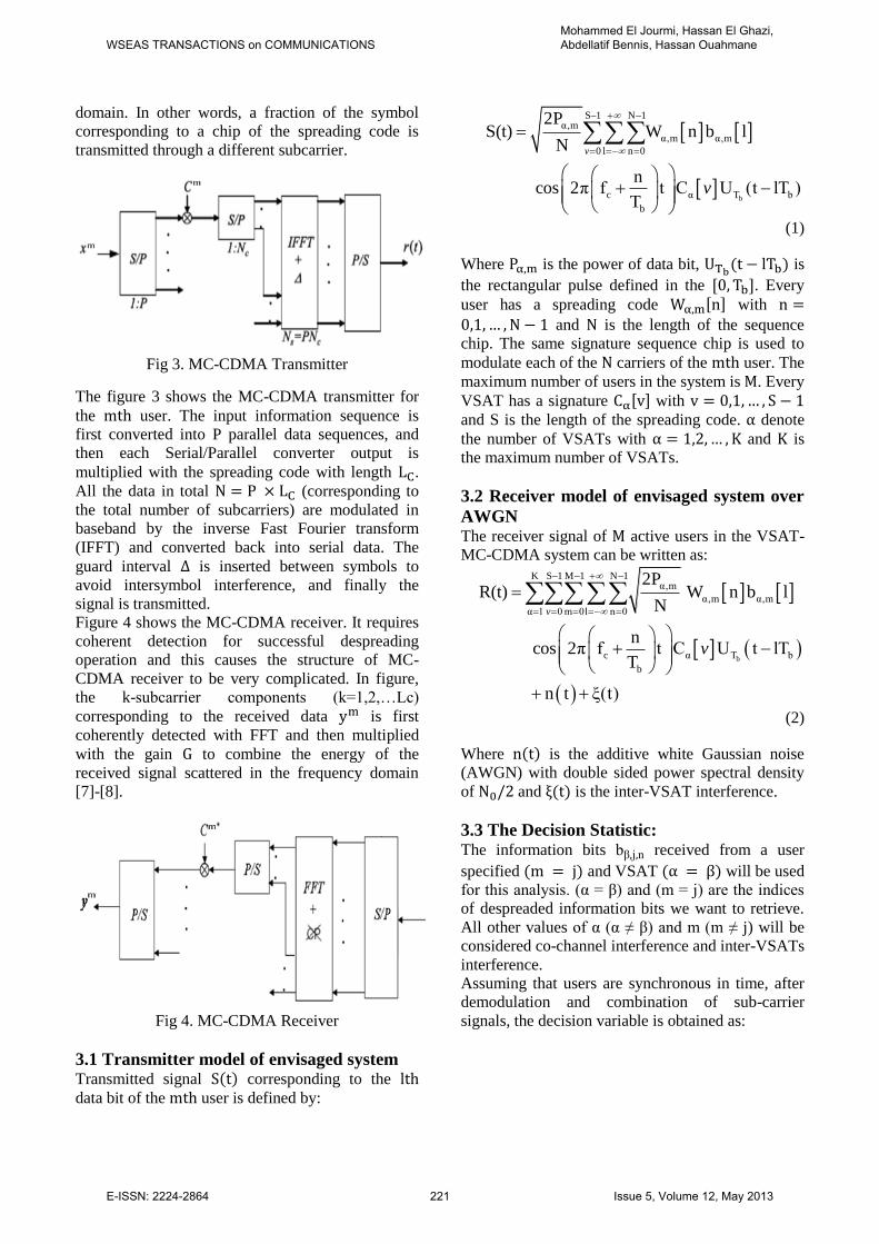
domain. In other words, a fraction of the symbol
corresponding to a chip of the spreading code is
transmitted through a different subcarrier.
Fig 3. MC-CDMA Transmitter
The figure 3 shows the MC-CDMA transmitter for
the user. The input information sequence is
first converted into P parallel data sequences, and
then each Serial/Parallel converter output is
multiplied with the spreading code with length .
All the data in total (corresponding to
the total number of subcarriers) are modulated in
baseband by the inverse Fast Fourier transform
(IFFT) and converted back into serial data. The
guard interval is inserted between symbols to
avoid intersymbol interference, and finally the
signal is transmitted.
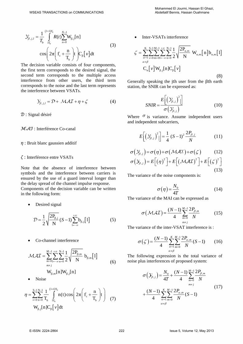
Figure 4 shows the MC-CDMA receiver. It requires
coherent detection for successful despreading
operation and this causes the structure of MC-
CDMA receiver to be very complicated. In figure,
the k-subcarrier components (k=1,2,…Lc)
corresponding to the received data is first
coherently detected with FFT and then multiplied
with the gain to combine the energy of the
received signal scattered in the frequency domain
[7]-[8].
Fig 4. MC-CDMA Receiver
3.1 Transmitter model of envisaged system Transmitted signal corresponding to the
data bit of the user is defined by:
b
S 1 N 1α,m
α,m α,m
0 l n 0
c α T b
b
2PS(t) W n b l
N
n cos 2π f t C U (t lT )
T
v
v
(1)
Where is the power of data bit, is
the rectangular pulse defined in the . Every
user has a spreading code with and is the length of the sequence
chip. The same signature sequence chip is used to
modulate each of the carriers of the user. The
maximum number of users in the system is . Every
VSAT has a signature with
and S is the length of the spreading code. denote
the number of VSATs with and is
the maximum number of VSATs.
3.2 Receiver model of envisaged system over
AWGN The receiver signal of active users in the VSAT-
MC-CDMA system can be written as:
b
K S 1 M 1 N 1α,m
α,m α,m
α 1 0m 0l n 0
c α T b
b
2PR(t) W n b l
N
n cos 2π f t C U t lT
T
n t ξ(t)
v
v
(2)
Where is the additive white Gaussian noise
(AWGN) with double sided power spectral density
of and is the inter-VSAT interference.
3.3 The Decision Statistic: The information bits b n received from a user
specified and VSAT will be used
for this analysis. (α = ) and (m = ) are the indices
of despreaded information bits we want to retrieve.
All other values of α (α ≠ ) and m (m ≠ j) will be
considered co-channel interference and inter-VSATs
interference.
Assuming that users are synchronous in time, after
demodulation and combination of sub-carrier
signals, the decision variable is obtained as:
WSEAS TRANSACTIONS on COMMUNICATIONSMohammed El Jourmi, Hassan El Ghazi, Abdellatif Bennis, Hassan Ouahmane
E-ISSN: 2224-2864 221 Issue 5, Volume 12, May 2013
1 1
, , β, j
0
c β
b
1( ) W [n]
n cos 2π f t C dt
T
b
b
l T N
j l
nb lT
R tT
v
(3)
The decision variable consists of four components,
the first term corresponds to the desired signal, the
second term corresponds to the multiple access
interference from other users, the third term
corresponds to the noise and the last term represents
the interference between VSATs.
, ,j l (4)
: Signal désiré
: Interférence Co-canal
: Bruit blanc gaussien additif
: Interférence entre VSATs
Note that the absence of interference between
symbols and the interference between carriers is
ensured by the use of a guard interval longer than
the delay spread of the channel impulse response.
Components of the decision variable can be written
in the following form:
Desired signal
β, j
β, j
l
2P1 ( 1) b l
2 NS
(5)
Co-channel interference
1 N 1
β,m
β,m0l n 0
β,m β, j
2P1 b l
2 N
W [n]W [n]
M
m
m j
(6)
Noise
b
b
l 1 TS 1 N 1
c
0 n 0 b blT
β, j β
1 nn(t)cos 2π f t
T T
W [n]C dt
v
v
(7)
Inter-VSATs interference
K S 1 M 1 N 1α,m
α,m α,m1 0 m 0l n 0
α β, j β
2P1 W n b l
2 N
C W [n]C
v
v v
(8)
Generally speaking the user from the earth
station, the SNIR can be expressed as:
2
,
,
j
j
ESNIR
(10)
Where is variance. Assume independent users
and independent subcarriers,
2 ,2
,
21 ( 1)
4
j
j
PE S
N
(11)
, j (12)
2 2 2
, j E E E
(13) The variance of the noise components is:
0
4
N
T (14)
The variance of the MAI can be expressed as
1
,
0
2( 1)
4
Mm
m
m j
PN
N
(15)
The variance of the inter-VSAT interference is :
1
,
1 0
2( 1)( 1)
4
K Mm
m
PNS
N
(16)
The following expression is the total variance of
noise plus interferences of proposed system:
1
,0,
0
1,
1 0
2( 1)
4 4
2( 1) ( 1)
4
Mm
jm
m j
K Mm
m
PN N
T N
PNS
N
(17)
WSEAS TRANSACTIONS on COMMUNICATIONSMohammed El Jourmi, Hassan El Ghazi, Abdellatif Bennis, Hassan Ouahmane
E-ISSN: 2224-2864 222 Issue 5, Volume 12, May 2013
4 Convolutional coding A convolutional encoder generates code symbols for
transmission utilizing a sequential finite-state
machine driven by the information sequence.
Decoding these codes then amounts to sequentially
observing a corrupted version of the output of this
system and attempting to infer the input sequence.
From a formal perspective, there is no need to
divide the message into segments of some specific
length.
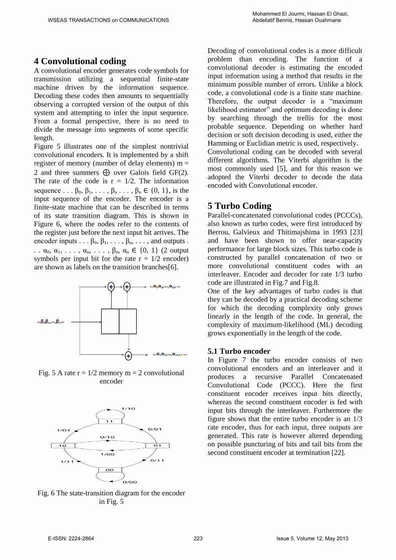
Figure 5 illustrates one of the simplest nontrivial
convolutional encoders. It is implemented by a shift
register of memory (number of delay elements) m =
2 and three summers ⊕ over Galois field GF(2).
The rate of the code is r = 1/2. The information
sequence . . . 0, 1, . . . , n . . . , n ∈ {0, 1}, is the
input sequence of the encoder. The encoder is a
finite-state machine that can be described in terms
of its state transition diagram. This is shown in
Figure 6, where the nodes refer to the contents of
the register just before the next input bit arrives. The
encoder inputs . . . 0, 1, . . . , n, . . . , and outputs .
. . α0, α1, . . . , αn, . . . , n, αn ∈ {0, 1} (2 output
symbols per input bit for the rate r = 1/2 encoder)
are shown as labels on the transition branches[6].
Fig. 5 A rate r = 1/2 memory m = 2 convolutional
encoder
Fig. 6 The state-transition diagram for the encoder
in Fig. 5
Decoding of convolutional codes is a more difficult
problem than encoding. The function of a
convolutional decoder is estimating the encoded
input information using a method that results in the
minimum possible number of errors. Unlike a block
code, a convolutional code is a finite state machine.
Therefore, the output decoder is a “maximum
likelihood estimator” and optimum decoding is done
by searching through the trellis for the most
probable sequence. Depending on whether hard
decision or soft decision decoding is used, either the
Hamming or Euclidian metric is used, respectively.
Convolutional coding can be decoded with several
different algorithms. The Viterbi algorithm is the
most commonly used [5], and for this reason we
adopted the Viterbi decoder to decode the data
encoded with Convolutional encoder.
5 Turbo Coding Parallel-concatenated convolutional codes (PCCCs),
also known as turbo codes, were first introduced by
Berrou, Galvieux and Thitimajshima in 1993 [23]
and have been shown to offer near-capacity
performance for large block sizes. This turbo code is
constructed by parallel concatenation of two or
more convolutional constituent codes with an
interleaver. Encoder and decoder for rate 1/3 turbo
code are illustrated in Fig.7 and Fig.8.
One of the key advantages of turbo codes is that
they can be decoded by a practical decoding scheme
for which the decoding complexity only grows
linearly in the length of the code. In general, the
complexity of maximum-likelihood (ML) decoding
grows exponentially in the length of the code.
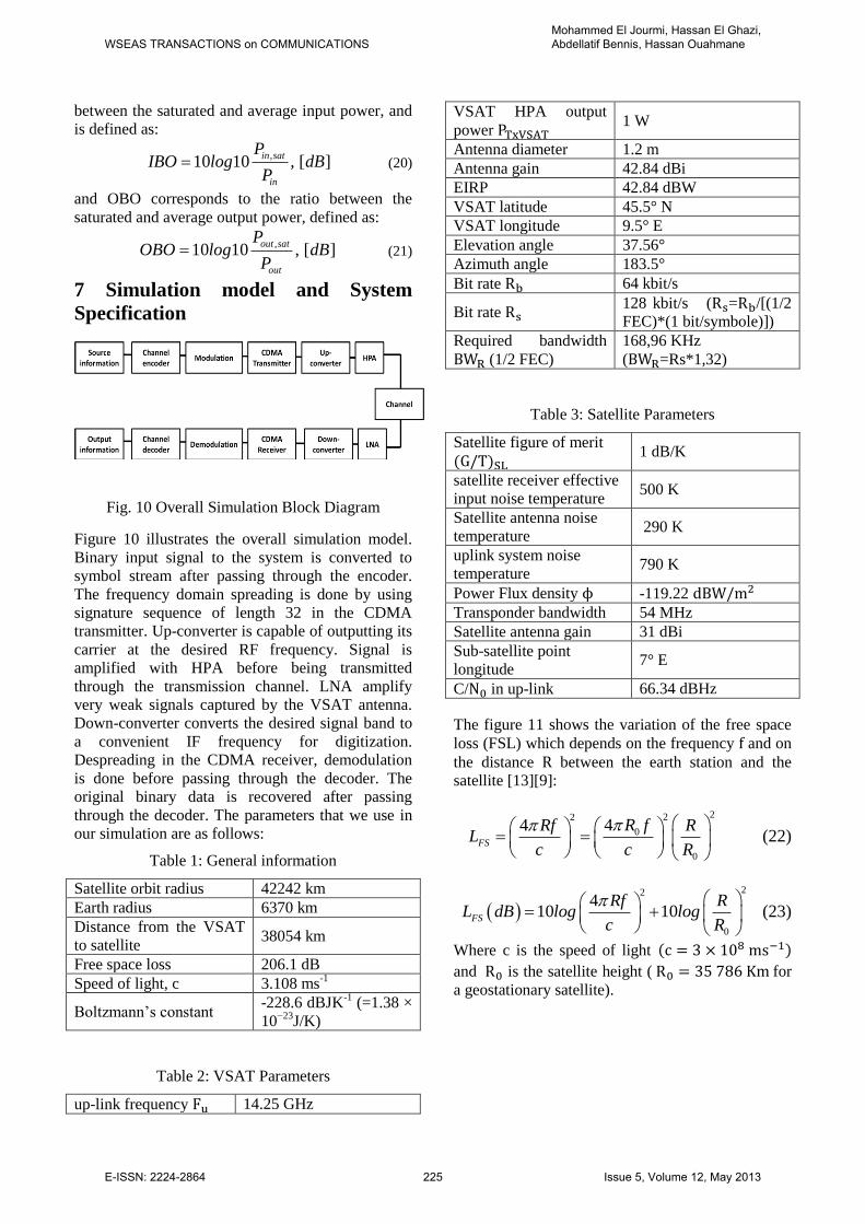
5.1 Turbo encoder In Figure 7 the turbo encoder consists of two
convolutional encoders and an interleaver and it
produces a recursive Parallel Concatenated
Convolutional Code (PCCC). Here the first
constituent encoder receives input bits directly,
whereas the second constituent encoder is fed with
input bits through the interleaver. Furthermore the
figure shows that the entire turbo encoder is an 1/3
rate encoder, thus for each input, three outputs are
generated. This rate is however altered depending
on possible puncturing of bits and tail bits from the
second constituent encoder at termination [22].
WSEAS TRANSACTIONS on COMMUNICATIONSMohammed El Jourmi, Hassan El Ghazi, Abdellatif Bennis, Hassan Ouahmane
E-ISSN: 2224-2864 223 Issue 5, Volume 12, May 2013
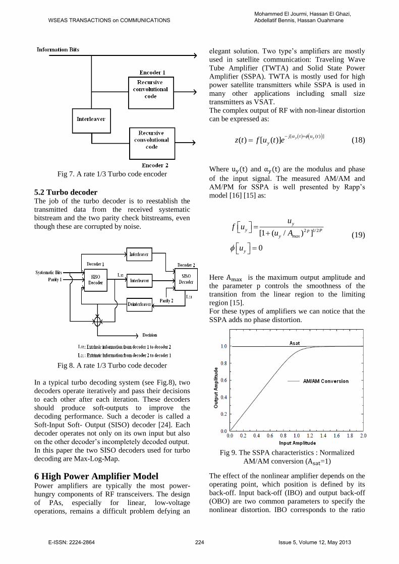
Fig 7. A rate 1/3 Turbo code encoder
5.2 Turbo decoder The job of the turbo decoder is to reestablish the
transmitted data from the received systematic
bitstream and the two parity check bitstreams, even
though these are corrupted by noise.
Fig 8. A rate 1/3 Turbo code decoder
In a typical turbo decoding system (see Fig.8), two
decoders operate iteratively and pass their decisions
to each other after each iteration. These decoders
should produce soft-outputs to improve the
decoding performance. Such a decoder is called a
Soft-Input Soft- Output (SISO) decoder [24]. Each
decoder operates not only on its own input but also
on the other decoder’s incompletely decoded output.
In this paper the two SISO decoders used for turbo
decoding are Max-Log-Map.
6 High Power Amplifier Model Power amplifiers are typically the most power-
hungry components of RF transceivers. The design
of PAs, especially for linear, low-voltage
operations, remains a difficult problem defying an
elegant solution. Two type’s amplifiers are mostly
used in satellite communication: Traveling Wave
Tube Amplifier (TWTA) and Solid State Power
Amplifier (SSPA). TWTA is mostly used for high
power satellite transmitters while SSPA is used in
many other applications including small size
transmitters as VSAT.
The complex output of RF with non-linear distortion
can be expressed as:
[ ( ) ]( ) [ ( )] y yj t u t
yz t f u t e
(18)
Where and are the modulus and phase
of the input signal. The measured AM/AM and
AM/PM for SSPA is well presented by Rapp’s
model [16] [15] as:
2 1/2 [1 ( / ) ]
0
y
y p P
y max
y
uf u
u A
u
(19)
Here is the maximum output amplitude and
the parameter p controls the smoothness of the
transition from the linear region to the limiting
region [15].
For these types of amplifiers we can notice that the
SSPA adds no phase distortion.
Fig 9. The SSPA characteristics : Normalized
AM/AM conversion ( =1)
The effect of the nonlinear amplifier depends on the
operating point, which position is defined by its
back-off. Input back-off (IBO) and output back-off
(OBO) are two common parameters to specify the
nonlinear distortion. IBO corresponds to the ratio
WSEAS TRANSACTIONS on COMMUNICATIONSMohammed El Jourmi, Hassan El Ghazi, Abdellatif Bennis, Hassan Ouahmane
E-ISSN: 2224-2864 224 Issue 5, Volume 12, May 2013
between the saturated and average input power, and
is defined as:
,10 10 , [ ]
in sat
in
PIBO log dB
P (20)
and OBO corresponds to the ratio between the
saturated and average output power, defined as:
,10 10 , [ ]
out sat
out
POBO log dB
P (21)
7 Simulation model and System
Specification
Fig. 10 Overall Simulation Block Diagram
Figure 10 illustrates the overall simulation model.
Binary input signal to the system is converted to
symbol stream after passing through the encoder.
The frequency domain spreading is done by using
signature sequence of length 32 in the CDMA
transmitter. Up-converter is capable of outputting its
carrier at the desired RF frequency. Signal is
amplified with HPA before being transmitted
through the transmission channel. LNA amplify
very weak signals captured by the VSAT antenna.
Down-converter converts the desired signal band to
a convenient IF frequency for digitization.
Despreading in the CDMA receiver, demodulation
is done before passing through the decoder. The
original binary data is recovered after passing
through the decoder. The parameters that we use in
our simulation are as follows:
Table 1: General information
Satellite orbit radius 42242 km
Earth radius 6370 km
Distance from the VSAT
to satellite 38054 km
Free space loss 206.1 dB
Speed of light, c 3.108 ms-1
Boltzmann’s constant -228.6 dBJK
-1 (=1.38 ×
10−23
J/K)
Table 2: VSAT Parameters
up-link frequency 14.25 GHz
VSAT HPA output
power 1 W
Antenna diameter 1.2 m
Antenna gain 42.84 dBi
EIRP 42.84 dBW
VSAT latitude 45.5° N
VSAT longitude 9.5° E
Elevation angle 37.56°
Azimuth angle 183.5°
Bit rate 64 kbit/s
Bit rate 128 kbit/s ( = /[(1/2
FEC)*(1 bit/symbole)])
Required bandwidth
(1/2 FEC)
168,96 KHz
( =Rs*1,32)
Table 3: Satellite Parameters
Satellite figure of merit
1 dB/K
satellite receiver effective
input noise temperature 500 K
Satellite antenna noise
temperature 290 K
uplink system noise
temperature 790 K
Power Flux density -119.22
Transponder bandwidth 54 MHz
Satellite antenna gain 31 dBi
Sub-satellite point
longitude 7° E
C/ in up-link 66.34 dBHz
The figure 11 shows the variation of the free space
loss (FSL) which depends on the frequency and on
the distance between the earth station and the
satellite [13][9]:
222
0
0
44FS
R fRf RL
c c R
(22)
22
0
410 10FS
Rf RL dB log log
c R
(23)
Where c is the speed of light
and is the satellite height ( for
a geostationary satellite).
WSEAS TRANSACTIONS on COMMUNICATIONSMohammed El Jourmi, Hassan El Ghazi, Abdellatif Bennis, Hassan Ouahmane
E-ISSN: 2224-2864 225 Issue 5, Volume 12, May 2013
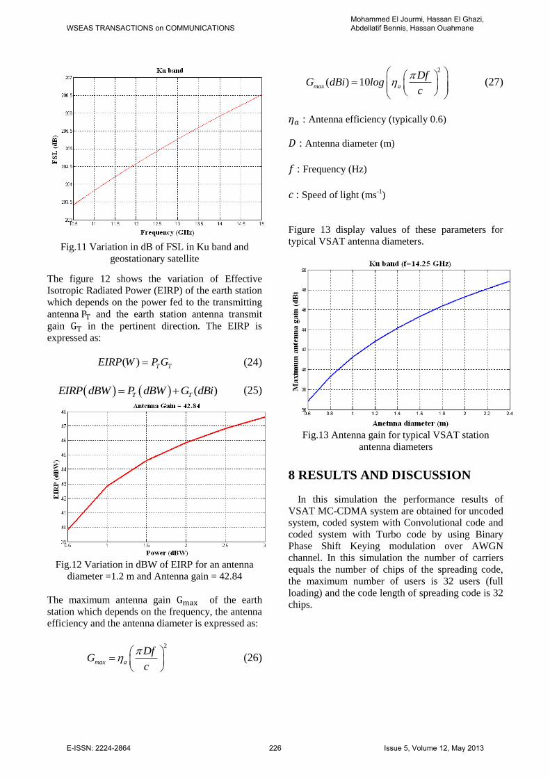
Fig.11 Variation in dB of FSL in Ku band and
geostationary satellite
The figure 12 shows the variation of Effective
Isotropic Radiated Power (EIRP) of the earth station
which depends on the power fed to the transmitting
antenna and the earth station antenna transmit
gain in the pertinent direction. The EIRP is
expressed as:
( ) T TEIRP W P G (24)
( )T TEIRP dBW P dBW G dBi (25)
Fig.12 Variation in dBW of EIRP for an antenna
diameter =1.2 m and Antenna gain = 42.84
The maximum antenna gain of the earth
station which depends on the frequency, the antenna
efficiency and the antenna diameter is expressed as:
2
max a
DfG
c
(26)
2
( ) 10max a
DfG dBi log
c
(27)
: Antenna efficiency (typically 0.6)
: Antenna diameter (m)
: Frequency (Hz)
: Speed of light (ms-1
)
Figure 13 display values of these parameters for
typical VSAT antenna diameters.
Fig.13 Antenna gain for typical VSAT station
antenna diameters
8 RESULTS AND DISCUSSION
In this simulation the performance results of
VSAT MC-CDMA system are obtained for uncoded
system, coded system with Convolutional code and
coded system with Turbo code by using Binary
Phase Shift Keying modulation over AWGN
channel. In this simulation the number of carriers
equals the number of chips of the spreading code,
the maximum number of users is 32 users (full
loading) and the code length of spreading code is 32
chips.
WSEAS TRANSACTIONS on COMMUNICATIONSMohammed El Jourmi, Hassan El Ghazi, Abdellatif Bennis, Hassan Ouahmane
E-ISSN: 2224-2864 226 Issue 5, Volume 12, May 2013
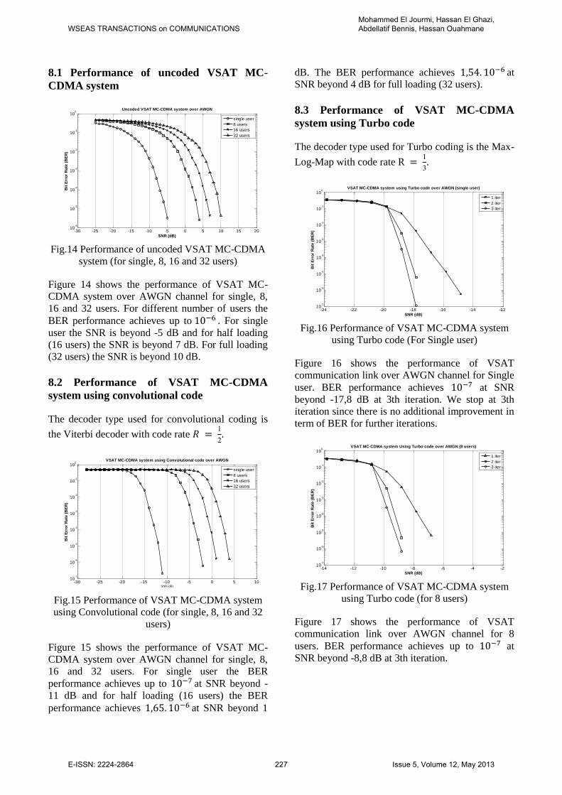
8.1 Performance of uncoded VSAT MC-
CDMA system
Fig.14 Performance of uncoded VSAT MC-CDMA
system (for single, 8, 16 and 32 users)
Figure 14 shows the performance of VSAT MC-
CDMA system over AWGN channel for single, 8,
16 and 32 users. For different number of users the
BER performance achieves up to . For single
user the SNR is beyond -5 dB and for half loading
(16 users) the SNR is beyond 7 dB. For full loading
(32 users) the SNR is beyond 10 dB.
8.2 Performance of VSAT MC-CDMA
system using convolutional code
The decoder type used for convolutional coding is
the Viterbi decoder with code rate 1
2.
Fig.15 Performance of VSAT MC-CDMA system
using Convolutional code (for single, 8, 16 and 32
users)
Figure 15 shows the performance of VSAT MC-
CDMA system over AWGN channel for single, 8,
16 and 32 users. For single user the BER
performance achieves up to at SNR beyond -
11 dB and for half loading (16 users) the BER
performance achieves at SNR beyond 1
dB. The BER performance achieves at
SNR beyond 4 dB for full loading (32 users).
8.3 Performance of VSAT MC-CDMA
system using Turbo code
The decoder type used for Turbo coding is the Max-
Log-Map with code rate 1
.
Fig.16 Performance of VSAT MC-CDMA system
using Turbo code (For Single user)
Figure 16 shows the performance of VSAT
communication link over AWGN channel for Single
user. BER performance achieves at SNR
beyond -17,8 dB at 3th iteration. We stop at 3th
iteration since there is no additional improvement in
term of BER for further iterations.
Fig.17 Performance of VSAT MC-CDMA system
using Turbo code (for 8 users)
Figure 17 shows the performance of VSAT
communication link over AWGN channel for 8
users. BER performance achieves up to at
SNR beyond -8,8 dB at 3th iteration.
-30 -25 -20 -15 -10 -5 0 5 10 15 2010
-6
10-5
10-4
10-3
10-2
10-1
100
SNR (dB)
Bit
Err
or
Rate
(B
ER
)
Uncoded VSAT MC-CDMA system over AWGN
single user
8 users
16 users
32 users
-30 -25 -20 -15 -10 -5 0 5 1010
-7
10-6
10-5
10-4
10-3
10-2
10-1
100
SNR (dB)
Bit
Err
or
Rate
(B
ER
)
VSAT MC-CDMA system using Convolutional code over AWGN
single user
8 users
16 users
32 users
-24 -22 -20 -18 -16 -14 -1210
-7
10-6
10-5
10-4
10-3
10-2
10-1
100
SNR (dB)B
it E
rro
r R
ate
(B
ER
)
VSAT MC-CDMA system using Turbo code over AWGN (single user)
1 iter
2 iter
3 iter
-14 -12 -10 -8 -6 -4 -210
-7
10-6
10-5
10-4
10-3
10-2
10-1
100
SNR (dB)
Bit
Err
or
Rate
(B
ER
)
VSAT MC-CDMA system Using Turbo code over AWGN (8 users)
1 iter
2 iter
3 iter
WSEAS TRANSACTIONS on COMMUNICATIONSMohammed El Jourmi, Hassan El Ghazi, Abdellatif Bennis, Hassan Ouahmane
E-ISSN: 2224-2864 227 Issue 5, Volume 12, May 2013
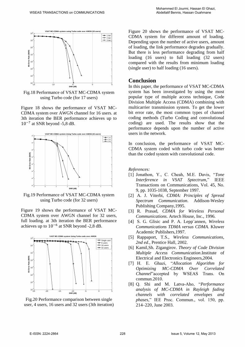
Fig.18 Performance of VSAT MC-CDMA system
using Turbo code (for 17 users)
Figure 18 shows the performance of VSAT MC-
CDMA system over AWGN channel for 16 users. at
3th iteration the BER performance achieves up to
at SNR beyond -5,8 dB.
Fig.19 Performance of VSAT MC-CDMA system
using Turbo code (for 32 users)
Figure 19 shows the performance of VSAT MC-
CDMA system over AWGN channel for 32 users,
full loading. at 3th iteration the BER performance
achieves up to at SNR beyond -2,8 dB.
Fig.20 Performance comparison between single
user, 4 users, 16 users and 32 users (3th iteration)
Figure 20 shows the performance of VSAT MC-
CDMA system for different amount of loading.
Depending upon the number of active users, amount
of loading, the link performance degrades gradually.
But there is less performance degrading from half
loading (16 users) to full loading (32 users)
compared with the results from minimum loading
(single user) to half loading (16 users).
Conclusion In this paper, the performance of VSAT MC-CDMA
system has been investigated by using the most
popular type of multiple access technique, Code
Division Multiple Access (CDMA) combining with
multicarrier transmission system. To get the lower
bit error rate, the most common types of channel
coding methods (Turbo Coding and convolutional
coding) are used. The results show that the
performance depends upon the number of active
users in the network.
In conclusion, the performance of VSAT MC-
CDMA system coded with turbo code was better
than the coded system with convolutional code.
References:
[1] Jonathon, Y., C. Cheah, M.E. Davis, “Tone
Interference in VSAT Sptectrum,” IEEE
Transactions on Communications, Vol. 45, No.
9, pp. 1035-1038, September 1997.
[2] A. J. Viterbi, CDMA: Principles of Spread
Spectrum Communication. Addison-Wesley
Publishing Company,1995.
[3] R. Prasad, CDMA for Wireless Personal
Communications. Artech House, Inc., 1996.
[4] S. G. Glisic and P. A. Lepp¨annen, Wireless
Communications TDMA versus CDMA. Kluwer
Academic Publishers,1997.
[5] Rappaport, T.S., Wireless Communications,
2nd ed., Prentice Hall, 2002.
[6] Kamil,Sh. Zigangirov. Theory of Code Division
Multiple Access Communication.Institute of
Electrical and Electronics Engineers,2004.
[7] H. E. Ghazi, “Allocation Algorithm for
Optimizing MC-CDMA Over Correlated
Channel”accepted by WSEAS Trans. On
commun.2010.
[8] Q. Shi and M. Latva-Aho, “Performance
analysis of MC-CDMA in Rayleigh fading
channels with correlated envelopes and
phases,” IEE Proc. Commun., vol. 150, pp.
214–220, June 2003.
-15 -10 -5 0 510
-7
10-6
10-5
10-4
10-3
10-2
10-1
100
SNR (dB)
Bit
Err
or
Rate
(B
ER
)
VSAT MC-CDMA system using Turbo code over AWGN (16 users)
1 iter
2 iter
3 iter
-8 -6 -4 -2 0 2 4 610
-7
10-6
10-5
10-4
10-3
10-2
10-1
100
SNR (dB)
Bit
Err
or
Rate
(B
ER
)
VAST MC-CDMA system Using Turbo code over AWGN (32 users)
1 iter
2 iter
3 iter
-25 -20 -15 -10 -5 0 510
-7
10-6
10-5
10-4
10-3
10-2
10-1
100
SNR (dB)
Bit
Err
or
Ra
te (
BE
R)
VAST MC-CDMA system Using Turbo code over AWGN
Single user
8 users
16 users
32 users
WSEAS TRANSACTIONS on COMMUNICATIONSMohammed El Jourmi, Hassan El Ghazi, Abdellatif Bennis, Hassan Ouahmane
E-ISSN: 2224-2864 228 Issue 5, Volume 12, May 2013
[9] Maral, G. 1996. VSAT Networks. New York:
John Wiley & Sons Ltd.
[10] John Wiley & Sons Ltd, The Atrium,
Southern Gate, Chichester, West Sussex PO19
8SQ, England. Theory and Applications of
OFDM and CDMA Wideband Wireless
Communications, 2005.
[11] Evans, B.G., Satellite Communication
Systems, 3rd ed., United Kingdom. The
Institution of Electrical Engineers, 1999.
[12] Elbert, B.R., The Satellite Communication
Ground Segment and Earth Station Handbook,
Artech House, 2000.
[13] Elbert, B.R., Introduction to Satellite
Communication 3rd , Artech House, 2008.
[14] Moheb, H., C. Robinson, J. Kijeski,
“Design and Development of Co-Polarized Ku-
band Ground Terminal System for VSAT
Application,” IEEE Publications 0-7803-5639-
X/99, pp. 2158-2161, 1999.
[15] R. zayani, S. Zid, R. Bouallegue, «
Simulateur des non-linéarités HPA sur un
système OFDM » OHD Conference, septembre
2005.
[16] A. N. D’Andrea, V. Lottici and R.
Reggiannin, «Nonlinear Predistortion of OFDM
Signals over Frequency-Selective Fading
Channels», IEEE Transactions on
Communications. Vol. 49. N° 5. pp. 837-843.
2001.
[17] G. L. Stuber, Principles of Mobile
Communications. Kluwer Academic
Publishers,1996.
[18] W. C. Jakes, Microwave Mobile
Communications. IEEE Press, 1974.
[19] J. Cavers, Mobile Channel Characteristics.
Kluwer Academic Publishers, 2000.
[20] F. Adachi, D. Garg, S. Takaoka, and K.
Takeda, “Broadband CDMA techniques,” IEEE
Wireless Communications, vol. 12, no. 2, pp. 8–
1/8, April 2005.
[21] R. V. Nee and R. Prasad, OFDM For
Wireless Multimedia Communications. Artech
House, 2000.
[22] 3GPP, \3GPP TS 45.003 V7.5.0." Internet,
2008.
[23] C. Berrou, A. Galvieux, and P.
Thitima shima, “Near Shannon limit error-
correcting coding and decoding: Turbo-codes,”
in Proc. 1993 IEEE Int. Conf. Commun.,
Geneva, Switzerland, 1993, vol. 2, pp. 1064–
1070.
[24] B. Sklar, Digital Communications:
Fundamentals and Applications. Second ed.
Fundamentals of Turbo Codes. 2001: Prentice
Hall.
WSEAS TRANSACTIONS on COMMUNICATIONSMohammed El Jourmi, Hassan El Ghazi, Abdellatif Bennis, Hassan Ouahmane
E-ISSN: 2224-2864 229 Issue 5, Volume 12, May 2013