Embed Size (px)
Citation preview
HELSINKI UNIVERSITY OF TECHNOLOGY
Parth Amin
Performance analysis and enhancementsof packet forwarding in LTE
Master's Thesis
Espoo, Aug, 2009
Supervisors: Professor Sasu Tarkoma, Helsinki University of Technology, Finland
Professor Jens Zander, Royal Institute of Technology, Sweden
Instructor: M.Sc. Anna Larmo, Ericsson Research, NomadicLab, Finland
HELSINKI UNIVERSITY OF ABSTRACT OFTECHNOLOGY MASTER'S THESISFaculty of Information and Natural SciencesDegree Programme of Security and Mobile Computing
Author: Parth AminTitle of thesis:Performance analysis and enhancements of packet forwarding in LTE
Date: Aug, 2009 Pages: 11 + 55Professorship: Data Communications Software Code: T-110Supervisors: Professor Sasu Tarkoma, TKK, Finland
Professor Jens Zander, KTH, SwedenInstructor: M.Sc. Anna Larmo, Ericsson Research, Finland
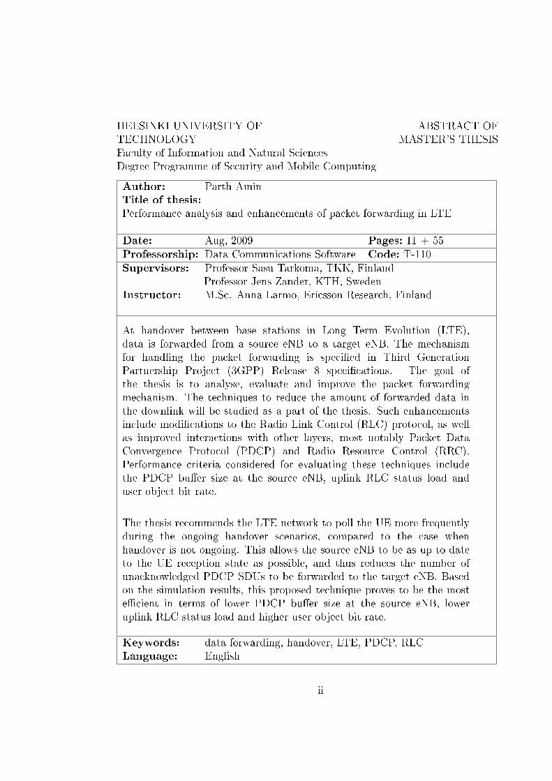
At handover between base stations in Long Term Evolution (LTE),data is forwarded from a source eNB to a target eNB. The mechanismfor handling the packet forwarding is speci�ed in Third GenerationPartnership Project (3GPP) Release 8 speci�cations. The goal ofthe thesis is to analyse, evaluate and improve the packet forwardingmechanism. The techniques to reduce the amount of forwarded data inthe downlink will be studied as a part of the thesis. Such enhancementsinclude modi�cations to the Radio Link Control (RLC) protocol, as wellas improved interactions with other layers, most notably Packet DataConvergence Protocol (PDCP) and Radio Resource Control (RRC).Performance criteria considered for evaluating these techniques includethe PDCP bu�er size at the source eNB, uplink RLC status load anduser object bit rate.
The thesis recommends the LTE network to poll the UE more frequentlyduring the ongoing handover scenarios, compared to the case whenhandover is not ongoing. This allows the source eNB to be as up to dateto the UE reception state as possible, and thus reduces the number ofunacknowledged PDCP SDUs to be forwarded to the target eNB. Basedon the simulation results, this proposed technique proves to be the moste�cient in terms of lower PDCP bu�er size at the source eNB, loweruplink RLC status load and higher user object bit rate.
Keywords: data forwarding, handover, LTE, PDCP, RLCLanguage: English
ii
Acknowledgements
This master thesis has been carried out at NomadicLab, Ericsson Research,Finland. I want to express my gratitude to Anna Larmo who has been myinstructor at Ericsson, for all her innovative ideas, time and help with theimplementation. Moreover, she also showed astonishing patience while ex-plaining the concepts and correcting the thesis. This work would not havebeen possible without her help.
I would also like to express my gratitude to Professor Sasu Tarkoma andProfessor Jens Zander, who are my supervisors from TKK and KTH respec-tively. They have given me great advice, supported and reviewed my work.
I would also like to thank my manager Johan Torsner, for giving me thiswonderful oppurtunity to work at NomadicLab and also for all the healthydiscussions we had throughout my stay. I would also like to thank my desk-top neighbor Stefan Wager for several insightful discussions. Last but notthe least, the whole access stratum research team at NomadicLab rocks forall the interesting and di�erent people exchanging ideas during co�ee breaks,lunch tables and meetings. NomadicLab has a fantastic working environ-ment, with full of brilliant people all around.
Finally, I want to thank my parents and friends for all their support through-out my work. A well balanced social and professional life has brought thebest out of me.
Espoo, Aug, 2009
Parth Amin
iii
Abbreviations and Acronyms
1G First Generation2G Second Generation3G Third Generation4G Fourth Generation3GPP Third Generation Partnership ProjectAM Acknowledged ModeAMC Adaptive Modulation and CodingAMPS Advanced Mobile Phone ServiceAQM Active Queue ManagementARQ Automatic Repeat RequestAS Access StratumBCCH Broadcast Control ChannelBCH Broadcast ChannelCCCH Common Control ChannelCDMA Code Division Multiple AccessCN Core NetworkCP Control PlaneCQI Channel Quality IndicatorC-RNTI Cell Radio Network Temporary IdentityDAB Digital Audio BroadcastDCCH Dedicated Control ChannelDECT Digital Enhanced Cordless TelecommunicationsDHCP Dynamic Host Con�guration ProtocolDL DownlinkDL-SCH Downlink Shared ChannelDRB Data Radio BearerDRX Discontinuous ReceptionDTCH Dedicated Tra�c ChannelDVB Digital Video BroadcastEDGE Enhanced Data rates for GSM EvolutioneMBMS Enhanced Multimedia Broadcast/Multicast Service
iv
eNB E-UTRAN NodeBEPC Evolved Packet CoreEPS Evolved Packet SystemE-UTRAN Evolved UMTS Terrestrial Radio Access NetworkFCC Federal Communications CommissionFDD Frequency Division DuplexFDMA Frequency Division Multiple AccessGERAN GSM Evolution Radio Access NetworkGPRS General Packet Radio ServicesGSM Global System for Mobile TelephonyHSDPA High Speed Downlink Packet AccessHSUPA High Speed Uplink Packet AccessIEEE Institute of Electrical and Electronics EngineersIMT-2000 International Mobile Telecommunications-2000IP Internet ProtocolITU International Telecommunication UnionLTE Long Term EvolutionMAC Medium Access ControlMIMO Multiple Input Multiple OutputMME Mobility Management EntityMMS Multimedia Messaging ServiceMR Measurement ReportMU-MIMO Multi-User MIMONAS Non-Access StratumNMT Nordic Mobile Telephony SystemOFDM Orthogonal Frequency Division MultiplexingOFDMA Orthogonal Frequency Division Multiple AccessPAPR Peak to Average Power RadioPBCH Physical Broadcast ChannelPCCH Paging Control ChannelPCH Paging ChannelPDCP Packet Data Convergence ProtocolPDN Packet Data NetworkPDSCH Physical Downlink Shared ChannelPDU Protocol Data UnitP-GW Packet Data Network GatewayPRACH Physical Random Access ChannelPUSCH Physical Uplink Shared ChannelQAM Quadrature Amplitude ModulationQoS Quality Of ServiceQPSK Quadrature Phase Shift Keying
v
RACH Random Access ChannelRAN Radio Access NetworkRFPA Radio Frequency Power Ampli�erRLC Radio Link ControlRRC Radio Resource ControlRRM Radio Resource ManagementSC-FDMA Single Carrier Frequency Division Multiple AccessSDMA Spatial Division Multiple AccessSDU Service Data UnitS-GW Serving GatewaySMS Short Message ServiceSON Self Organizing NetworksSRB Signaling Radio BearersTDD Time Division DuplexTDMA Time Division Multiple AccessTM Transparent ModeTTI Transmit Time IntervalUE User EquipmentUICC Universal Integrated Circuit CardUL UplinkUL-SCH Uplink Shared ChannelUM Unacknowledged ModeUMTS Universal Mobile Telecommunications SystemUP User PlaneUSIM Universal Subscriber Identity ModuleWAP Wireless Application ProtocolWCDMA Wideband CDMA
vi
Contents
Abbreviations and Acronyms iv
1 Problem De�nition 1
2 Mobile Communication History and Evolution 3
3 Long Term Evolution (LTE) 9
3.1 LTE Performance Targets . . . . . . . . . . . . . . . . . . . . 9
3.2 LTE Multiple Access Technologies . . . . . . . . . . . . . . . . 11
3.3 LTE System Architecture . . . . . . . . . . . . . . . . . . . . 15
3.3.1 Logical Elements in LTE . . . . . . . . . . . . . . . . . 15
3.4 LTE Radio Access Stratum . . . . . . . . . . . . . . . . . . . . 19
3.4.1 Medium Access Control Protocol . . . . . . . . . . . . 19
3.4.2 Radio Link Control Protocol . . . . . . . . . . . . . . . 22
3.4.3 Packet Data Convergence Protocol . . . . . . . . . . . 24
3.4.4 Radio Resource Control Protocol . . . . . . . . . . . . 26
4 Data forwarding 28
4.1 Mobility Management . . . . . . . . . . . . . . . . . . . . . . 29
4.2 Data Forwarding Mechanism . . . . . . . . . . . . . . . . . . . 32
4.3 Problem with the Data Forwarding . . . . . . . . . . . . . . . 34
4.4 Existing Work to Improve the Data Forwarding Mechanism . . 34
4.5 Proposed Solutions to Improve the Data Forwarding Mechanism 36
vii
5 Simulation Results 39
5.1 Problem Formulation . . . . . . . . . . . . . . . . . . . . . . . 39
5.2 Simulation Environment and System Model . . . . . . . . . . 39
5.3 Simulation Results . . . . . . . . . . . . . . . . . . . . . . . . 43
6 Conclusion 52
7 Future Work 53
viii
List of Tables
5.1 LTE environment simulation parameters . . . . . . . . . . . . 42
ix
List of Figures
2.1 Evolution of the wireless system . . . . . . . . . . . . . . . . . 6
2.2 Expected Broadband Growth 2007-2014 [1] . . . . . . . . . . . 7
2.3 Comparision of the packet/voice tra�c in the WCDMA net-works [1] . . . . . . . . . . . . . . . . . . . . . . . . . . . . . . 8
3.1 LTE downlink physical resource based on OFDMA [2] . . . . . 12
3.2 Overview of the LTE architecture [3] . . . . . . . . . . . . . . 15
3.3 Functional split between E-UTRAN and EPC [4] . . . . . . . 17
3.4 LTE control plane [5] . . . . . . . . . . . . . . . . . . . . . . . 20
3.5 LTE user plane [5] . . . . . . . . . . . . . . . . . . . . . . . . 20
3.6 Mapping of the uplink logical, transport and physical channels[6] . . . . . . . . . . . . . . . . . . . . . . . . . . . . . . . . . 21
3.7 Mapping of the downlink logical, transport and physical chan-nels [6] . . . . . . . . . . . . . . . . . . . . . . . . . . . . . . . 22
3.8 RLC Polling PDU/Status Report exchange [7] . . . . . . . . . 24
3.9 E-UTRAN RRC States and state transitions among 3GPPSystems [8] . . . . . . . . . . . . . . . . . . . . . . . . . . . . 26
4.1 Forwarded data at the source eNB during handover . . . . . . 29
4.2 Intra LTE handover with data forwarding [4] . . . . . . . . . . 30
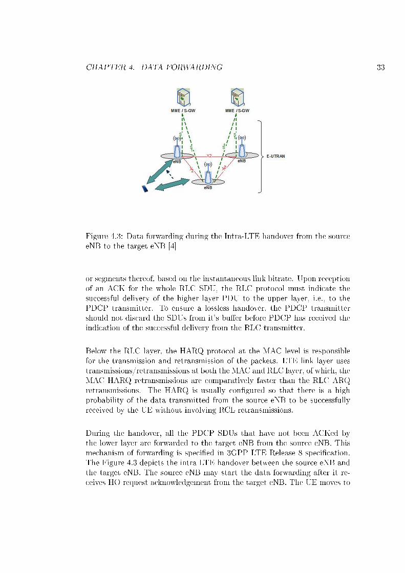
4.3 Data forwarding during the Intra-LTE handover from the sourceeNB to the target eNB [4] . . . . . . . . . . . . . . . . . . . . 33
5.1 Simulator Protocol Stack . . . . . . . . . . . . . . . . . . . . . 40
5.2 CDF for PDCP Bu�er Size comparing the proposed methodswith existing ones . . . . . . . . . . . . . . . . . . . . . . . . . 46
x
5.3 CDF for PDCP Bu�er Size comparing the the two proposedvariants of changing the UE polling frequency . . . . . . . . . 48
5.4 CDF for PDCP Bu�er Size based on increasing the UE pollingfrequency . . . . . . . . . . . . . . . . . . . . . . . . . . . . . 49
5.5 CDF for Object bit rate . . . . . . . . . . . . . . . . . . . . . 51
xi
Chapter 1
Problem De�nition
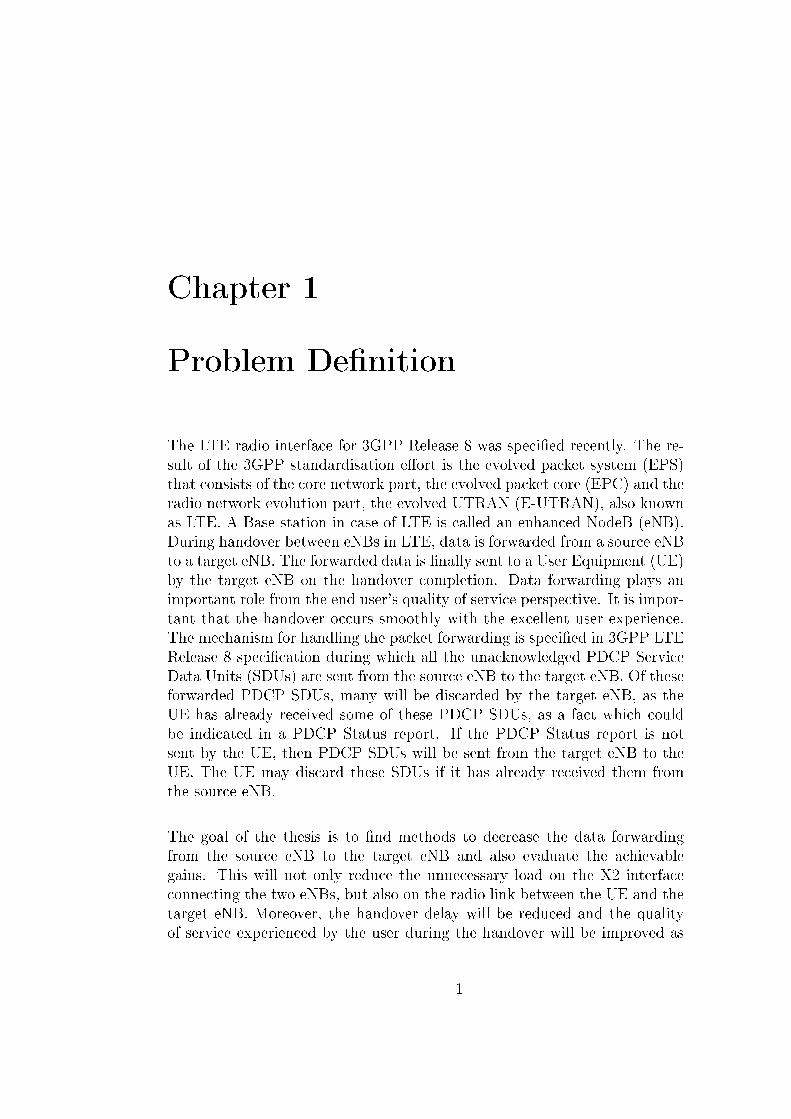
The LTE radio interface for 3GPP Release 8 was speci�ed recently. The re-sult of the 3GPP standardisation e�ort is the evolved packet system (EPS)that consists of the core network part, the evolved packet core (EPC) and theradio network evolution part, the evolved UTRAN (E-UTRAN), also knownas LTE. A Base station in case of LTE is called an enhanced NodeB (eNB).During handover between eNBs in LTE, data is forwarded from a source eNBto a target eNB. The forwarded data is �nally sent to a User Equipment (UE)by the target eNB on the handover completion. Data forwarding plays animportant role from the end user's quality of service perspective. It is impor-tant that the handover occurs smoothly with the excellent user experience.The mechanism for handling the packet forwarding is speci�ed in 3GPP LTERelease 8 speci�cation during which all the unacknowledged PDCP ServiceData Units (SDUs) are sent from the source eNB to the target eNB. Of theseforwarded PDCP SDUs, many will be discarded by the target eNB, as theUE has already received some of these PDCP SDUs, as a fact which couldbe indicated in a PDCP Status report. If the PDCP Status report is notsent by the UE, then PDCP SDUs will be sent from the target eNB to theUE. The UE may discard these SDUs if it has already received them fromthe source eNB.
The goal of the thesis is to �nd methods to decrease the data forwardingfrom the source eNB to the target eNB and also evaluate the achievablegains. This will not only reduce the unnecessary load on the X2 interfaceconnecting the two eNBs, but also on the radio link between the UE and thetarget eNB. Moreover, the handover delay will be reduced and the qualityof service experienced by the user during the handover will be improved as
1
CHAPTER 1. PROBLEM DEFINITION 2
a result. The scope of the thesis is limited to the forwarded data in thedownlink, not considering the uplink data to be re-transmitted by the UE tothe target eNB after the handover.
Chapter 2
Mobile Communication Historyand Evolution
The evolution roadmap of radio communications [9] from the �rst exper-iments done by Guglielmo Marconi in the 1890s to the present advancedmobile telephony system has been quite long. To understand the present,complex 3G mobile-communication system, it is important to understandits evolution right from the beginning. Cellular system has evolved from anexpensive technology for a selected few individuals to today's global mobilecommunication system.
AT&T started the �rst commercial car-borne telephony service in 1946, whichwas approved by US Federal Communications Commission (FCC). It wasalso the one, who introduced the cellular concept of reusing radio frequen-cies, which formed the basis to all subsequent mobile communication systems.Commercial mobile telephony continued to be car-borne, for many years be-cause of bulky and power-hungry equipment.
The analog Nordic Mobile Telephony System (NMT) was the �rst inter-national mobile communication system. NMT was introduced in the Nordiccountries in 1981, at the same time as analog Advanced Mobile Phone Service(AMPS) was introduced in North America. These analog cellular systems arealso known as the First Generation (1G) of mobile communication system.They supported telephony services based on voice. It still had problems suchas bulky mobile equipment and inconsistent voice quality with the cross-talkbetween users. The concept of Roaming, came with an international systemsuch as NMT, o�ering a service also for users traveling outside the area of
3
CHAPTER 2. MOBILE COMMUNICATION HISTORY AND EVOLUTION 4
their home operator. This gave a larger market for mobile phones, attractingmore companies into the mobile communication business.
With the advent of digital communication during the 1980s, the interestin developing a successor to the analog communication system materializedand provided the foundation towards the evolution of the Second Genera-tion (2G) of mobile communication system. With a digital technology, camean opportunity to increase the capacity of the system, give a more consis-tent quality of the service, and develop truly mobile devices. Global Systemfor Mobile Telephony (GSM) project was started to develop a pan-Europeanmobile-telephony system. After evaluations of Time Division Multiple Access(TDMA), Code Division Multiple Access (CDMA), and Frequency DivisionMultiple Access (FDMA) based proposals in the mid-1980s, the �nal GSMstandard was built based on TDMA.
GSM standards were based on narrowband, targeting the lowbandwidth voiceservices. With the 2G digital mobile communication, came also the opportu-nity to provide data services over the mobile communication network. Theprimary data services introduced in 2G were short message service (SMS)and circuit-switched data services enabling e-mail and other data applica-tions. The peak data rate in 2G was initially 9.6 kbps. Packet data overcellular systems became a reality, during the second half of the 1990s, withthe introduction of General Packet Radio Services (GPRS) and is referred toas 2.5G. GPRS supported the data rate of 56-114 kbps.
Wireless evolution continued further towards the Third Generation (3G) ofmobile communication system. International Mobile Telecommunications-2000 (IMT-2000), also known as the 3G, is a family of standards for wire-less communication de�ned by the International Telecommunication Union(ITU). It includes Enhanced Data rates for GSM Evolution (EDGE), Uni-versal Mobile Telecommunications System (UMTS), CDMA-2000, DigitalEnhanced Cordless Telecommunications (DECT) and WiMAX. Of these 3Gsystems, UMTS is seen as the most widely deployed system in the presentworld. UMTS is based on Wideband CDMA (WCDMA). With the adventof 3G came the possibilities for a range of new high rate data services thatwere only hinted at with 2G and 2.5G.
3G evolution is driven by the demands for the lower latency, higher datarates and capacity. UMTS o�ered a peak data rate of 384 kbps. With the
CHAPTER 2. MOBILE COMMUNICATION HISTORY AND EVOLUTION 5
introduction of High Speed Downlink Packet Access (HSDPA) in UMTS, thedownlink peak data rate was increased to 14 Mbps. Since there was alsoa demand for the faster uplink, enhanced uplink was added, which is alsoreferred to as High Speed Uplink Packet Access (HSUPA), with peak datarate of 5.8 Mbps. The combination of HSDPA and HSUPA is commonlyreferred to as HSPA. HSPA technology is presently evolving in 3GPP, underthe name Evolved HSPA and supports the downlink peak data rate of 42Mbps and uplink peak data rate of 22 Mbps.
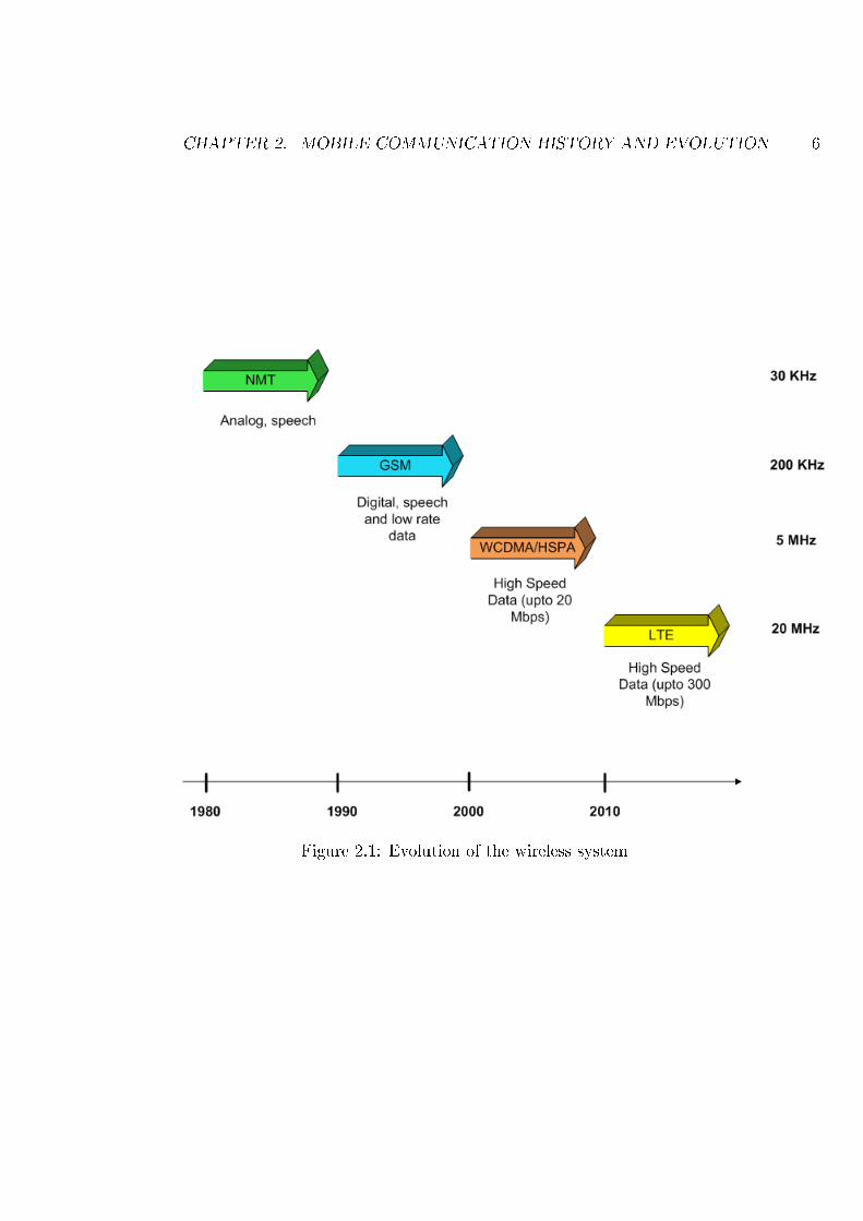
The latest step being studied and developed in 3GPP is an evolution of 3G to-wards an evolved radio access referred to as the LTE and the LTE-Advanced[10]. LTE-Advanced is seen as a candidate for the future Fourth Generation(4G) of mobile communication system. It is expected that deployment ofthe LTE systems will commence, by the end of the year 2009-2010. LTEwill bring improved support and performance for a real-time conversationaland interactive services, as it is based on technologies like Orthogonal Fre-quency Division Multiple Access (OFDMA), Multiple Input Multiple Outputantennas (MIMO), higher order adaptive modulations, architectural designsupporting lower latency and higher spectral e�ciency. Figure 2.1 depictsthe evolution of the wireless systems starting from 1G to the future 4G sys-tem.
People can already browse the internet or send e-mails using HSPA-enablednotebooks, replace their �xed DSL modems with HSPA modems or USB don-gles and send and receive video or music using 3G phones. With LTE, theuser experience will be even better. LTE will also enhance more demandingapplications such as interactive TV, mobile video blogging, advanced gamesand professional services. "All IP" is the buzzword in the present telecomindustry. More and more people are talking of IP telephony in the homeand at their work place. Usage of wireless data services is growing fasterthan ever before, moving us forward towards the age of mobile broadband.Both, the IP based Internet and the circuit switch based traditional tele-com networks are getting converged and moving towards the all IP basedwireless networks. The evolution towards all IP based wireless networks hasenabled the service developers to develop IP based services, that only theimagination and technology sets limits to. All these combinations of servicespoint towards the applications and services that consume higher data ratesand require lower delays compared to what today's mobile-communicationsystem can deliver. While demand for applications such as SMS, Web andWireless Application Protocol (WAP) access, Multimedia Messaging Service
CHAPTER 2. MOBILE COMMUNICATION HISTORY AND EVOLUTION 6
Figure 2.1: Evolution of the wireless system
CHAPTER 2. MOBILE COMMUNICATION HISTORY AND EVOLUTION 7
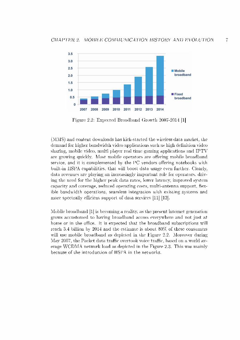
Figure 2.2: Expected Broadband Growth 2007-2014 [1]
(MMS) and content downloads has kick-started the wireless data market, thedemand for higher bandwidth video applications such as high de�nition videosharing, mobile video, multi player real time gaming applications and IPTVare growing quickly. Most mobile operators are o�ering mobile broadbandservice, and it is complemented by the PC vendors o�ering notebooks withbuilt-in HSPA capabilities, that will boost data usage even further. Clearly,data revenues are playing an increasingly important role for operators, driv-ing the need for the higher peak data rates, lower latency, improved systemcapacity and coverage, reduced operating costs, multi-antenna support, �ex-ible bandwidth operations, seamless integration with existing systems andmore spectrally e�cient support of data services [11] [12].
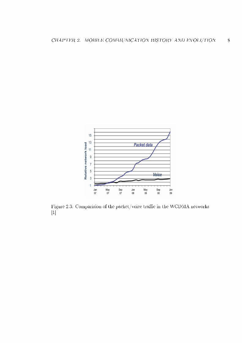
Mobile broadband [1] is becoming a reality, as the present internet generationgrows accustomed to having broadband access everywhere and not just athome or in the o�ce. It is expected that the broadband subscriptions willreach 3.4 billion by 2014 and the estimate is about 80% of these consumerswill use mobile broadband as depicted in the Figure 2.2. Moreover duringMay 2007, the Packet data tra�c overtook voice tra�c, based on a world av-erage WCDMA network load as depicted in the Figure 2.3. This was mainlybecause of the introduction of HSPA in the networks.
CHAPTER 2. MOBILE COMMUNICATION HISTORY AND EVOLUTION 8
Figure 2.3: Comparision of the packet/voice tra�c in the WCDMA networks[1]
Chapter 3
Long Term Evolution (LTE)
This chapter gives a short introduction to LTE. It starts with the LTE perfor-mance targets, explains the multiple access technology that forms the basisand �nally explains the LTE system architecture.
3.1 LTE Performance Targets
The radio access network architecture forms the basis of every mobile com-munication technology. LTE is one of the radio access technologies used toaccess the core network by the mobile. As the name suggests, LTE is consid-ered as a long term answer to overcoming the performance constraints of thepresent day 3G mobile radio access technology. With these considerations inmind, 3GPP rolled out the LTE track, which is seen as a roadmap towardsfuture 4G systems. The 3GPP design targets of the LTE system as de�nedin [13] are as follows:
1) Performance
The LTE system targets high spectral e�ciency of 2.5 bps/Hz in the uplink(UL) and 5 bps/Hz in the downlink (DL). For a 20 MHz spectrum allocation,this corresponds to 50 Mbps and 100 Mbps data rates in the UL and DL re-spectively, which is ten times more than HSPA Release 6. The best systemperformance is obtained at 0 - 15 km/h speeds. The LTE system is designedto support user mobility rates as high as 350 km/h. In noise limited scenar-ios, the system should satisfy the given performance metrics of throughput,
9
CHAPTER 3. LONG TERM EVOLUTION (LTE) 10
spectral e�ciency and mobility requirements for a 5 km cell radius. Accept-able degradations in system performance have been de�ned for cases such ashigh mobility and larger cell radius. The LTE framework aims to provideservices with reduced latency. The latency requirements are split betweenthe control-plane and the user-plane. The control-plane latency refers to thedelay in transition from di�erent non-active states to an active state. Theuser-plane latency refers to the delay in transmitting an Internet Protocol(IP) packet from the terminal to the Radio Access Network (RAN) edge nodeor vice-versa. LTE also supports enhanced Multimedia Broadcast/MulticastService (eMBMS) with the possibility to initiate simultaneous voice calls andMBMS.
2) Spectrum Allocation
The LTE system is designed to be deployable in the IMT-2000 frequencyband, so that the system can co-exist with the legacy GSM and UMTS net-works and also support inter operability between di�erent wireless systems.LTE can be deployed in both paired and unpaired spectrum allocations, i.e.the system should support both Frequency Division Duplex (FDD) and TimeDivision Duplex (TDD) modes. LTE also supports the bandwidth scalabil-ity and can operate in any of the LTE speci�c allocations of 1.25, 1.6, 2.5,5, 10, 15 and 20 MHz. The support for bandwidth scalability permits thedeployment of the LTE system in the existing 2G/3G spectrum and assistsin easier migration towards the higher spectrum allocations. 3GPP release 8de�nes 14 and 8 frequency bands for FDD and TDD respectively.
3) Architecture
The WCDMA access stratum was redesigned for the LTE to achieve thesigni�cantly reduced latency targets. Transition times from idle/dormantstates to active state (control plane) are reduced signi�cantly. Similarly, ra-dio access network latency is less than 5 ms in unloaded conditions for thesmall IP packet (user plane). LTE RAN is an all IP based architecture withsupport for the conversational and real-time tra�c as well. Compared toWCDMA/HSPA, the LTE network consists of a fewer number of networkelements/interfaces. The migration from hierarchical to �at network archi-tecture envisaged in LTE reduces network signaling and jitter. LTE basestations known as eNB provide the all-in-one radio access interface betweenthe UE and the Core Network (CN).
CHAPTER 3. LONG TERM EVOLUTION (LTE) 11
4) Cost
LTE supports self-organizing networks (SON) capability, o�ering the abilityto automate the network management processes. This intelligent mechanismcollects live network data and collectively diagnose a number of issues and�xes them in an optimal way. Thus, the LTE network reduces the opera-tor's network planning and maintenance costs. The idea is to minimize thelifecycle cost of running a network by eliminating manual con�guration ofequipment at the time of deployment and also to dynamically optimize theradio network performance during operation. The ultimate aim is to reducethe unit cost and retail price of wireless data services.
5) Security
A multi-layer, multi-vendor security paradigm is designed for LTE since se-curity challenges are signi�cant in IP networks. Strict user/operator au-thentication, authorization and auditing, secure data storage, con�gurationintegrity, secure network management and unsolicited tra�c protection areviewed as the major targets of LTE network security.
3.2 LTE Multiple Access Technologies
Some of the key features of LTE are multiple access schemes in UL/DL,adaptive modulation and coding, advanced MIMO spatial multiplexing tech-niques, support for both FDD and TDD mode and Hybrid Automatic RepeatRequest (HARQ) mechanisms. LTE multiple access is based on the followingtechniques [14] [15]:
1) Orthogonal Frequency Division Multiple Access (OFDMA) [16][17]
The DL LTE radio access is based on OFDMA. OFDMA meets the LTErequirement for spectrum �exibility and enables cost-e�cient solutions forwide carriers with high peak rates. OFDMA is a well-established technology,for example in standards such as Institute of Electrical and Electronics En-
CHAPTER 3. LONG TERM EVOLUTION (LTE) 12
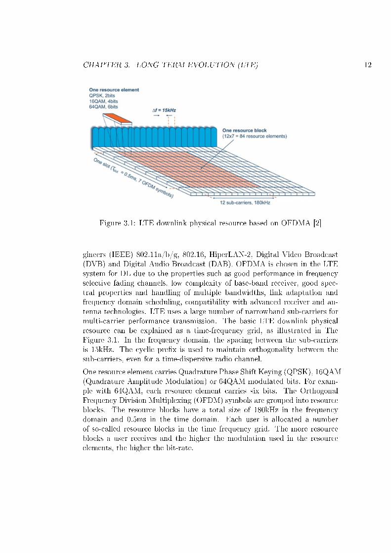
Figure 3.1: LTE downlink physical resource based on OFDMA [2]
gineers (IEEE) 802.11a/b/g, 802.16, HiperLAN-2, Digital Video Broadcast(DVB) and Digital Audio Broadcast (DAB). OFDMA is chosen in the LTEsystem for DL due to the properties such as good performance in frequencyselective fading channels, low complexity of base-band receiver, good spec-tral properties and handling of multiple bandwidths, link adaptation andfrequency domain scheduling, compatibility with advanced receiver and an-tenna technologies. LTE uses a large number of narrowband sub-carriers formulti-carrier performance transmission. The basic LTE downlink physicalresource can be explained as a time-frequency grid, as illustrated in TheFigure 3.1. In the frequency domain, the spacing between the sub-carriersis 15kHz. The cyclic pre�x is used to maintain orthogonality between thesub-carriers, even for a time-dispersive radio channel.
One resource element carries Quadrature Phase Shift Keying (QPSK), 16QAM(Quadrature Amplitude Modulation) or 64QAM modulated bits. For exam-ple with 64QAM, each resource element carries six bits. The OrthogonalFrequency Division Multiplexing (OFDM) symbols are grouped into resourceblocks. The resource blocks have a total size of 180kHz in the frequencydomain and 0.5ms in the time domain. Each user is allocated a numberof so-called resource blocks in the time frequency grid. The more resourceblocks a user receives and the higher the modulation used in the resourceelements, the higher the bit-rate.

CHAPTER 3. LONG TERM EVOLUTION (LTE) 13
2) Single Carrier Frequency Division Multiple Access (SC-FDMA)
The UL LTE radio access is based on a pre-coded version of OFDM calledSC-FDMA. The adoption of SC-FDMA for UL is motivated by the lowerPeak to Average Power Radio (PAPR) of the SC-FDMA waveform com-pared to OFDMA. With lower PAPR, e�cient radio frequency power ampli-�er (RFPA) operation can be attained, leading to longer battery life in thehandset. SC-FDMA solves this problem by grouping together the resourceblocks in a way that reduces the need for linearity and power consumption inthe power ampli�er. A low PAPR also improves coverage and the cell-edgeperformance. LTE utilizes single carrier modulation, DFT-spread orthogonalfrequency multiplexing and frequency domain equalization.
3) Advanced Antennas [18] [19]
Advanced antenna solutions introduced in HSPA Evolution are also used byLTE. Solutions incorporating multiple antennas meet next-generation mobilebroadband network requirements for high peak data rates, extended coverageand high capacity. Advanced multi-antenna solutions are vital to achievingthese targets. There is not one single antenna solution that can address everydeployment scenarios. Consequently, a family of antenna soultions is avail-able for speci�c deployment scenarios. For example, high peak data rates canbe achieved with multi-layer antenna solutions such as 2x2 or 4x4 MIMO,and extended coverage can be achieved with beam-forming. MIMO, one ofseveral forms of smart antenna technology, is the use of multiple antennas atboth the transmitter and receiver to improve communication performance.In addition to MIMO (single-user), LTE standard has adopted multi-userMIMO (MU-MIMO). MU-MIMO may be supported by transmitting di�er-ent data streams to di�erent users within the same resource region via spatialdivision multiple access (SDMA). MU-MIMO allows a terminal to transmitsignal to multiple users and also receive signal from multiple users in the sameband simultaneously. As multiple antennas are used at both the transmitterand receiver, it improves the communication performance by providing ad-ditional diversity against radio channel fading. MIMO enables features likebeam-forming, improved coverage, higher data throughput, higher spectrale�ciency, link reliability and diversity.
4) User scheduling
CHAPTER 3. LONG TERM EVOLUTION (LTE) 14
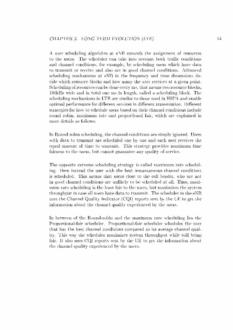
A user scheduling algorithm at eNB controls the assignment of resourcesto the users. The scheduler can take into account both tra�c conditionsand channel conditions, for example, by scheduling users which have datato transmit or receive and also are in good channel conditions. Advancedscheduling mechanisms at eNB in the frequency and time dimensions de-cide which resource blocks and how many the user receives at a given point.Scheduling of resources can be done every ms, that means two resource blocks,180kHz wide and in total one ms in length, called a scheduling block. Thescheduling mechanisms in LTE are similar to those used in HSPA and enableoptimal performance for di�erent services in di�erent transmission. Di�erentstrategies for how to schedule users based on their channel conditions includeround robin, maximum rate and proportional fair, which are explained inmore details as follows:
In Round robin scheduling, the channel conditions are simply ignored. Userswith data to transmit are scheduled one by one and each user receives theequal amount of time to transmit. This strategy provides maximum timefairness to the users, but cannot guarantee any quality of service.
The opposite extreme scheduling strategy is called maximum rate schedul-ing. Here instead the user with the best instantaneous channel conditionsis scheduled. This means that users close to the cell border, who are notin good channel conditions are unlikely to be scheduled at all. Thus, maxi-mum rate scheduling is the least fair to the users, but maximizes the systemthroughput in case all users have data to transmit. The scheduler in the eNBuses the Channel Quality Indicator (CQI) reports sent by the UE to get theinformation about the channel quality experienced by the users.
In between of the Round-robin and the maximum rate scheduling lies theProportional-fair scheduler. Proportional-fair scheduler schedules the userthat has the best channel conditions compared to its average channel qual-ity. This way the scheduler maximizes system throughput while still beingfair. It also uses CQI reports sent by the UE to get the information aboutthe channel quality experienced by the users.
CHAPTER 3. LONG TERM EVOLUTION (LTE) 15
Figure 3.2: Overview of the LTE architecture [3]
3.3 LTE System Architecture
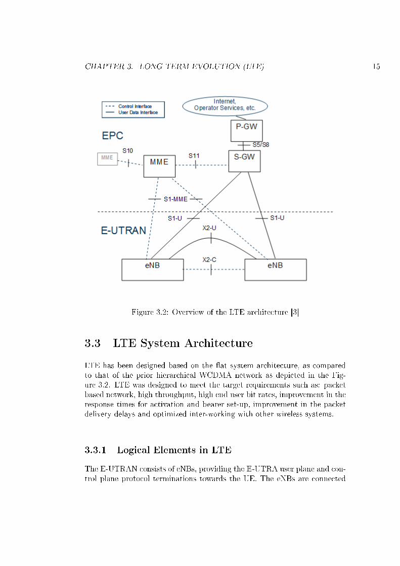
LTE has been designed based on the �at system architecture, as comparedto that of the prior hierarchical WCDMA network as depicted in the Fig-ure 3.2. LTE was designed to meet the target requirements such as: packetbased network, high throughput, high end user bit rates, improvement in theresponse times for activation and bearer set-up, improvement in the packetdelivery delays and optimized inter-working with other wireless systems.
3.3.1 Logical Elements in LTE
The E-UTRAN consists of eNBs, providing the E-UTRA user plane and con-trol plane protocol terminations towards the UE. The eNBs are connected
CHAPTER 3. LONG TERM EVOLUTION (LTE) 16
with each other by a logical interface called the X2 interface. The eNBs arealso connected by means of the S1 interface to the EPC, more speci�callyto the Mobility Management Entity (MME) by means of the S1-MME andto the Serving Gateway (S-GW) by means of the S1-U. It should be notedthat in practice the X2 link does not need to be separate from the S1, butthat X2 can be realized with the same physical connection and routed viathe S-GW. UE accesses the services o�ered by EPC through eNB. Each ofthese elements are explained brie�y as follows:
1) User Equipment (UE)
UE is the device used by the end user for communication, for e.g., smartphone, data card, or can also be embedded to a laptop. UE contains the Uni-versal Subscriber Identity Module (USIM) which is also called the TerminalEquipment (TE). USIM is an application placed into a removable smart cardcalled the Universal Integrated Circuit Card (UICC). UE is used to identifyand authenticate the user and to derive the security keys for protecting theradio interface transmission. Functionally, the UE is a platform for commu-nication applications, which communicate with the network for setting up,maintaining and removing the communication link the end user needs. UEalso participates in the mobility management functions such as handoversand reporting the terminal location as instructed by the network.
2) E-UTRAN NodeB (eNB)
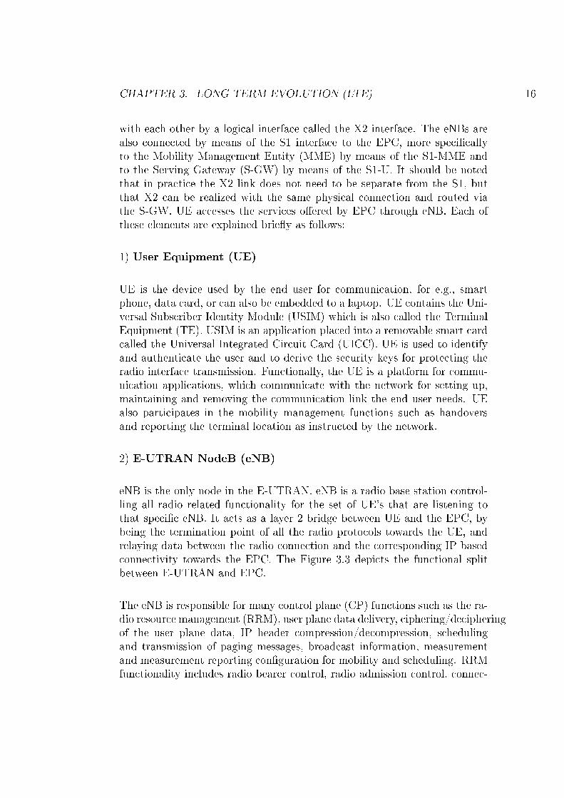
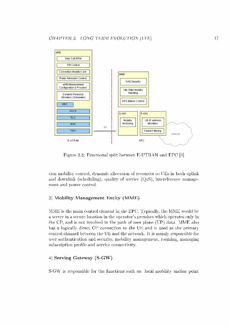
eNB is the only node in the E-UTRAN. eNB is a radio base station control-ling all radio related functionality for the set of UE's that are listening tothat speci�c eNB. It acts as a layer 2 bridge between UE and the EPC, bybeing the termination point of all the radio protocols towards the UE, andrelaying data between the radio connection and the corresponding IP basedconnectivity towards the EPC. The Figure 3.3 depicts the functional splitbetween E-UTRAN and EPC.
The eNB is responsible for many control plane (CP) functions such as the ra-dio resource management (RRM), user plane data delivery, ciphering/decipheringof the user plane data, IP header compression/decompression, schedulingand transmission of paging messages, broadcast information, measurementand measurement reporting con�guration for mobility and scheduling. RRMfunctionality includes radio bearer control, radio admission control, connec-
CHAPTER 3. LONG TERM EVOLUTION (LTE) 17
Figure 3.3: Functional split between E-UTRAN and EPC [4]
tion mobility control, dynamic allocation of resources to UEs in both uplinkand downlink (scheduling), quality of service (QoS), intereference manage-ment and power control.
3) Mobility Management Entity (MME)
MME is the main control element in the EPC. Typically, the MME would bea server in a secure location in the operator's premises which operates only inthe CP, and is not involved in the path of user plane (UP) data. MME alsohas a logically direct CP connection to the UE and is used as the primarycontrol channel between the UE and the network. It is mainly responsible foruser authentication and security, mobility management, roaming, managingsubscription pro�le and service connectivity.
4) Serving Gateway (S-GW)
S-GW is responsible for the functions such as: local mobility anchor point
CHAPTER 3. LONG TERM EVOLUTION (LTE) 18
for inter-eNB handover, mobility anchoring for inter-3GPP mobility, lawfulinterception, packet routing and forwarding, transport level packet markingin the uplink and the downlink and accounting the user. It is also responsiblefor UP tunnel management and switching. During mobility between eNBs,S-GW acts as the mobility anchor point. The MME commands the S-GW toswitch the tunnel from one eNodeB to another. The MME may also requestthe S-GW to provide tunnelling resources for data forwarding, when there isa need to forward data from the source eNB to the target eNB, during theongoing radio handover. The mobility scenarios also include changing fromone S-GW to another, and the MME controls this change accordingly, byremoving tunnels in the old S-GW and setting them up in a new S-GW.
In the connected state, the S-GW relays the data between eNB and P-GW.However, when a UE is in idle mode, the resources in eNodeB are released,and the data path terminates in the S-GW. If S-GW receives data packetsfrom P-GW on any such tunnel, S-GW will bu�er the packets, and requestthe MME to initiate paging of the UE. Paging will request the UE to re-connect, and when the tunnels are re-connected, the bu�ered packets will besent on. The S-GW will monitor data in the tunnels, and may also collectdata needed for accounting and user charging.
5) Packet Data Network Gateway (P-GW)
P-GW is responsible for functionalities such as per-user based packet �l-tering, lawful interception, UE IP address allocation, transport level packetmarking in the downlink, UL and DL service level charging, gating and rateenforcement. P-GW is the router connecting the EPS and external packetdata networks. It is the highest level mobility anchor in the system and alsois the IP point of attachment for the UE. When a UE moves from one S-GWto another, the bearers have to be switched in the P-GW. The P-GW willreceive an indication to switch the �ows from the new S-GW. P-GW is re-sponsible for the tra�c control functionalities such as gating and �ltering. Itallocates the IP address to the UE, which is used to communicate with otherIP hosts. The allocation of the IP address is done, when the UE requests aPacket Data Network (PDN) connection for getting attached to the network.Thus P-GW uses the Dynamic Host Con�guration Protocol (DHCP), to de-liver the IP address to the UE. Also, dynamic auto-con�guration is supportedby the standards. IPv4/IPv6 or both addresses may be allocated dependingon the need.
CHAPTER 3. LONG TERM EVOLUTION (LTE) 19
3.4 LTE Radio Access Stratum
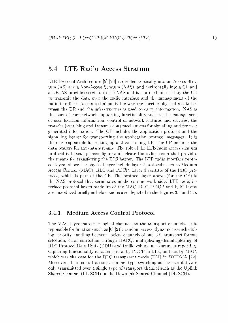
LTE Protocol Architecture [5] [20] is divided vertically into an Access Stra-tum (AS) and a Non-Access Stratum (NAS), and horizontally into a CP anda UP. AS provides services to the NAS and it is a medium used by the UEto transmit the data over the radio interface and the management of theradio interface. Access technique is the way the speci�c physical media be-tween the UE and the infrastructure is used to carry information. NAS isthe part of core network supporting functionality such as the managementof user location information, control of network features and services, thetransfer (switching and transmission) mechanisms for signalling and for usergenerated information. The CP includes the application protocol and thesignalling bearer for transporting the application protocol messages. It isthe one responsible for setting up and controlling UP. The UP includes thedata bearers for the data streams. The role of the LTE radio access stratumprotocol is to set up, recon�gure and release the radio bearer that providesthe means for transferring the EPS bearer. The LTE radio interface proto-col layers above the physical layer include layer 2 protocols such as MediumAccess Control (MAC), RLC and PDCP. Layer 3 consists of the RRC pro-tocol, which is part of the CP. The protocol layer above (for the CP) isthe NAS protocol that terminates in the core network side. LTE radio in-terface protocol layers made up of the MAC, RLC, PDCP and RRC layersare introduced brie�y as below and is also depicted in the Figures 3.4 and 3.5.
3.4.1 Medium Access Control Protocol
The MAC layer maps the logical channels to the transport channels. It isreponsible for functions such as [6] [21]: random access, dynamic user schedul-ing, priority handling between logical channels of one UE, transport formatselection, error correction through HARQ, multiplexing/demultiplexing ofRLC Protocol Data Units (PDU) and tra�c volume measurement reporting.Ciphering functionality is taken care of by PDCP in LTE, and not by MAC,which was the case for the RLC transparent mode (TM) in WCDMA [22].Moreover, there is no transport channel type switching as the user data areonly transmitted over a single type of transport channel such as the UplinkShared Channel (UL-SCH) or the Downlink Shared Channel (DL-SCH).
CHAPTER 3. LONG TERM EVOLUTION (LTE) 20
Figure 3.4: LTE control plane [5]
Figure 3.5: LTE user plane [5]
CHAPTER 3. LONG TERM EVOLUTION (LTE) 21
Figure 3.6: Mapping of the uplink logical, transport and physical channels[6]
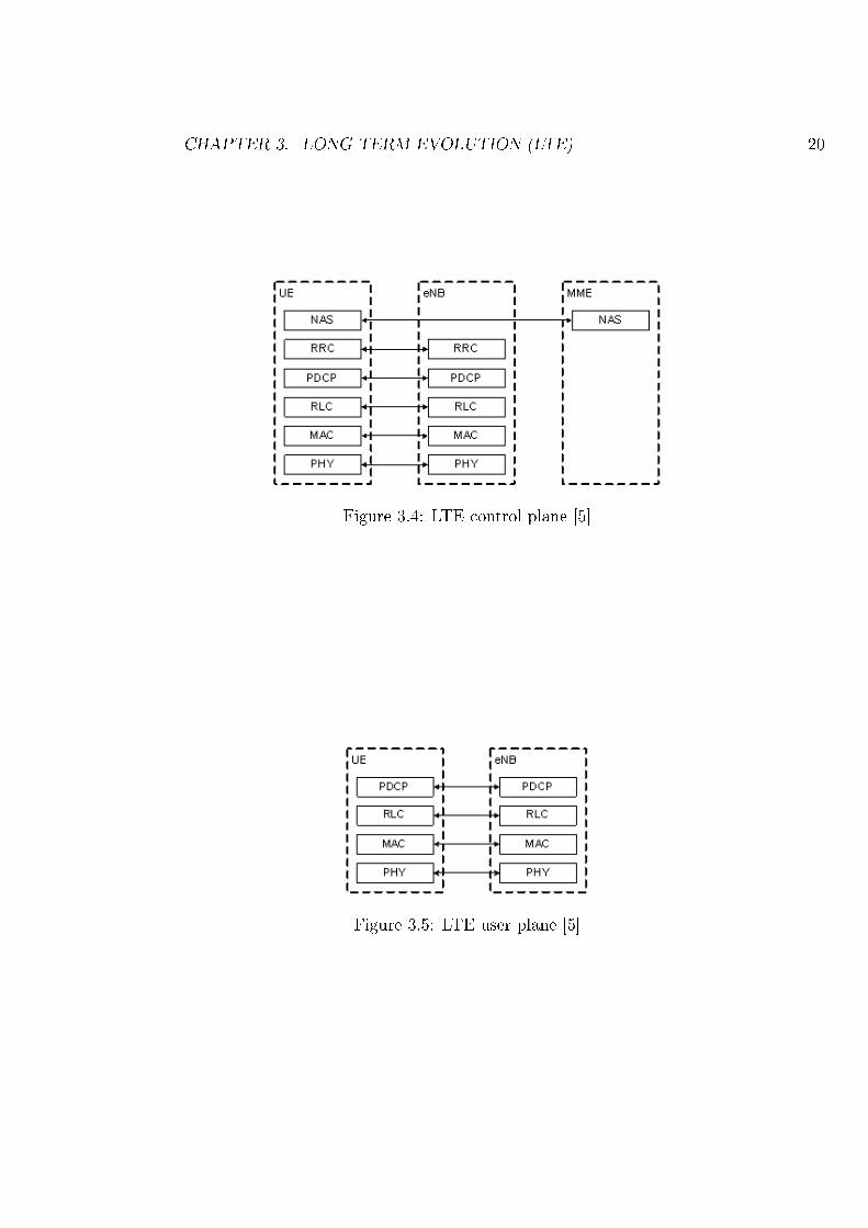
As depicted in the Figure 3.6, LTE uplink logical channels map to the LTEtransport channels. Common Control Channel (CCCH), Dedicated ControlChannel (DCCH) and Dedicated Tra�c Channel (DTCH) are the existingLTE uplink logical channels. In the uplink direction, all the logical chan-nels are mapped to the UL-SCH. There is no logical channel mapped onthe Random Access Channel (RACH), as it does not carry any informationabove the MAC layer. Similarly RACH maps further to the Physical randomaccess channel (PRACH), whereas, UL-SCH maps further to the Physical up-link shared channel (PUSCH).
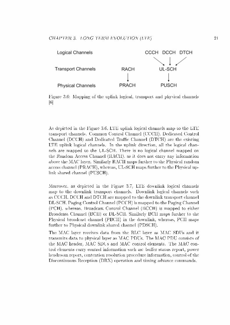
Moreover, as depicted in the Figure 3.7, LTE downlink logical channelsmap to the downlink transport channels. Downlink logical channels suchas CCCH, DCCH and DTCH are mapped to the downlink transport channelDL-SCH. Paging Control Channel (PCCH) is mapped to the Paging Channel(PCH), whereas, Broadcast Control Channel (BCCH) is mapped to eitherBroadcast Channel (BCH) or DL-SCH. Similarly BCH maps further to thePhysical broadcast channel (PBCH) in the downlink, whereas, PCH mapsfurther to Physical downlink shared channel (PDSCH).
The MAC layer receives data from the RLC layer as MAC SDUs and ittransmits data to physical layer as MAC PDUs. The MAC PDU consists ofthe MAC header, MAC SDUs and MAC control elements. The MAC con-trol elements carry control information such as: bu�er status report, powerheadroom report, contention resolution procedure information, control of theDiscontinuous Reception (DRX) operation and timing advance commands.
CHAPTER 3. LONG TERM EVOLUTION (LTE) 22
Figure 3.7: Mapping of the downlink logical, transport and physical channels[6]
3.4.2 Radio Link Control Protocol
The RLC layer is responsible for the functions such as [23] [24]: transfer-ring the SDUs received from higher layers, i.e. from RRC or PDCP to thelower MAC layer, error correction with ARQ, concatenation/segmentation,in-sequency delivery, duplicate detection, protocol error handling. Cipheringfunctionality is taken care of by PDCP in LTE, and not by RLC, which wasthe case for the non-transparent RLC mode (AM or UM) in WCDMA [22].Moreover, re-segmentation before RLC retransmission is enabled.
RLC Modes of operation
The RLC supports three di�erent modes of operation [15]:
1) Transparent Mode (TM)
In TM mode, the RLC does not add any headers to the delivered or receiveddata on a logical channel. The TM mode of operation is only suited for ser-vices that are not sensitive to delivery order. Thus from the logical channelonly BCCH, CCCH and PCCH can be operated in TM mode.
2) Unacknowledged Mode (UM)
The UM Data are segmented or concatenated to suitable size RLC PDUs andthen the UM header is added. Header is used for in-sequence delivery of datawhich might be received out of sequence due to HARQ operation in lower
CHAPTER 3. LONG TERM EVOLUTION (LTE) 23
layers. The RLC UM header includes the sequence number for facilitatingin-sequence delivery and duplicate packet detection. Logical channel DTCHcan be operated in UM mode.
3) Acknowledged Mode (AM)
RLC AM mode is typically used for best e�ort data transfer. Automatic Re-peat Request (ARQ) procedure, responsible for the transmission/retransmissionof the packets are only performed by an AM RLC entity. RLC AM modesupports the retransmission of the PDU's, if lost due to the operations inthe lower layer. Moreover, re-segmentation is also supported to �t the phys-ical layer resources available for retransmission. Logical channels DCCH orDTCH can be operated in AM mode.
The RLC layer receives data from the PDCP layer and stores it into thetransmission bu�er. Based on the resources available, data is either seg-mented or concatenated. An RLC PDU can either be a RLC data PDU ora RLC control PDU. RLC data PDUs are used by TM, UM and AM RLCentities to transfer upper layer data. RLC control PDUs are used by AMRLC entity to perform ARQ procedures. STATUS PDU is a RLC controlPDU, which is used by the receiving AM RLC entity to inform the transmit-ting AM RLC entity about AMD PDUs that are received successfully, andAMD PDUs that are detected to be lost by the receiving AM RLC entity.The transmitting side of an AM RLC entity can receive a negative acknowl-edgement for an AMD PDU or a portion of an AMD PDU. When receiving anegative acknowledgement for an AMD PDU or a portion of an AMD PDUby a STATUS PDU from its peer AM RLC entity, the transmitting side ofthe AM RLC entity shall retransmit that PDU.
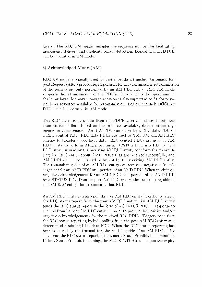
An AM RLC entity can also poll its peer AM RLC entity in order to triggerthe RLC status report from the peer AM RLC entity. An AM RLC entitysends the RLC status report in the form of a STATUS PDU, in response tothe poll from its peer AM RLC entity in order to provide the positive and/ornegative acknowledgements for the received RLC PDUs. Triggers to initiatethe RLC status reporting include polling from the peer AM RLC entity anddetection of a missing RLC data PDU. When the RLC status reporting hasbeen triggered by the transmitter, the receiving side of an AM RLC entityshall send the RLC status report, if the timer t-StatusProhibit is not running.If the t-StatusProhibit is running, the RLC STATUS is sent upon the expiry
CHAPTER 3. LONG TERM EVOLUTION (LTE) 24
Figure 3.8: RLC Polling PDU/Status Report exchange [7]
of the timer. RLC UE receiver t-StatusProhibit timer is used by the UE'sreceiving side of an AM RLC entity in order to prohibit the transmission ofthe STATUS PDU. The Figure 3.8 depicts the RLC polling / Status reportexchange mechanism, without the t-StatusProhibit timer.
3.4.3 Packet Data Convergence Protocol
The PDCP layer [25] [26] is located above the RLC layer. RLC and PDCPhave interactions especially at the time of re-establishment, which is per-formed, e.g., at handover. The key functionalities of the PDCP includeheader compression and decompression, transfer of user data, in-sequencedelivery of upper layer PDUs at PDCP re-establishment procedure for RLCAM, duplicate detection of lower layer SDUs at PDCP re-establishment pro-cedure for RLC AM, retransmission of PDCP SDUs at handover for RLCAM, ciphering and deciphering, timer-based SDU discard in uplink, transfer
CHAPTER 3. LONG TERM EVOLUTION (LTE) 25
of control plane data.
The PDCP layer receives PDCP SDUs from the NAS/RRC and after cipher-ing and other actions, the data are forwarded to the RLC layer. Correspond-ingly, in the receiving side the data are received from the RLC layer. ThePDCP layer is responsible for the data forwarding functionality in connec-tion with the intra LTE handover events for the DL. The PDCP layer atthe source eNB will forward the non-delivered packets to the target eNB. Inthe UL, PDCP retransmits all the packets to the target eNB, which have notbeen successfully acknowledged by lower layers, as the RLC is reset and MACHARQ bu�er is �ushed at handover. Both of these techniques in UL/DL willensure that no data is lost in connection with the handover event betweenthe LTE eNBs.
Header compression and corresponding decompression of the IP packets isbased on the Robust Header Compression (ROHC) protocol. The ROHCprotocol is speci�ed by the IETF. On PDCP, the ROHC functionality canbe used for all IP data on the DRBs both in RLC AM and UM mode. TheROHC is an optional feature in the speci�cation, and thus the network candecide to turn the feature on or o� in the UE [8] depending on its own andthe UEs capabilities.
The key di�erence to WCDMA is that now all user data go via the PDCPlayer, as PDCP is responsible for the ciphering of the data. The cipheringis applied to the data part of the PDCP data PDUs on both control anduser plane. PDCP control PDUs are not ciphered. Signaling Radio Bearers(SRB) use integrity protection in addition to ciphering, i.e., the possibilityto identify the source of a control message is who it claims to be.
The timer based SDU discard in the UL is an optional feature con�gured bythe network. All PDCP SDUs being queued for more than the con�guredtime are discarded to prevent transmission of outdated information. Thetimer could be seen as a simplistic Active Queue Management (AQM) func-tion. To disable the function, the timer value is set to in�nity.
The PDCP Status reporting is also an optional feature that can be con�g-ured by the network. The Status reports can be sent from the UE or tothe UE. The main function of the Status report is to decrease the amountof data transmitted over the air due to PDCP level retransmissions after a
CHAPTER 3. LONG TERM EVOLUTION (LTE) 26
Figure 3.9: E-UTRAN RRC States and state transitions among 3GPP Sys-tems [8]
handover. The uplink and downlink status reports are con�gured separately,i.e. only either or, none, or both can be used. The optional PDCP Sta-tus report includes the First Missing PDCP SN in the receiver, optionally abitmap consisting of information on out-of-sequence reception from the RLCat re-establishment in the same receiver.
3.4.4 Radio Resource Control Protocol
The RRC layer functionality includes [8]: broadcast of system information,RRC connection control, inter/intra RAT mobility, cell selection/reselection,measurement control, paging, transfer of dedicated control information forthe speci�c UE, security key management, self-con�guration and self-optimisation.
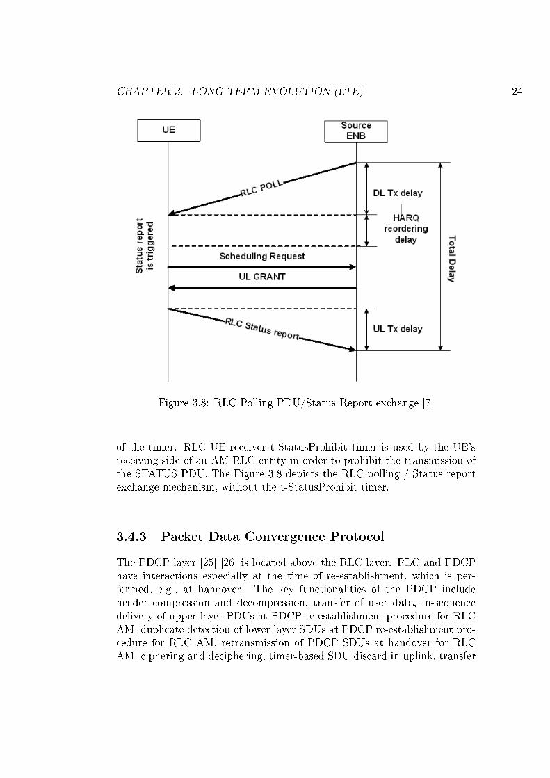
Contrary to the UMTS, UE states in LTE are simpli�ed signi�cantly to onlytwo states, i.e., RRC-CONNECTED and RRC-IDLE, depending on whetherthe RRC connection has been established or not. In the RRC-IDLE state,the UE listens to the paging channel to track the incoming calls, acquiresthe system information and also performs neighboring cell measurement andcell (re)selection. LTE network con�gures UE speci�c Discontinuous Re-
CHAPTER 3. LONG TERM EVOLUTION (LTE) 27
ception (DRX) in the UE [27]. In the RRC-CONNECTED state, the UEtransfers data to the network and also receives data from the network. Forthis, the UE monitors control channels that are associated with the shareddata channel to determine if data are scheduled for the speci�c UE and pro-vides channel quality feedback to the eNB. Moreover the UE also performsthe neighboring cell measurements and measurement reporting based on thecon�guration con�gured by the eNB. UE mobility i.e. handover is controlledby the network in RRC-CONNECTED state. The Figure 3.9 compares themobility support between E-UTRAN, UTRAN and GSM Enhanced DataRates for GSM Evolution Radio Access Network (GERAN). As the CELL-FACH state in UTRAN is considered a very short period, a direct transitionfrom UTRAN CELL-FACH to E-UTRAN RRC state is not supported.
Chapter 4
Data forwarding
LTE supports network controlled handover, based on measurements per-formed and reported by the UE. The source eNB may forward the unacknowl-edged data to the target eNB, during the ongoing handover for the speci�cUE. Moreover, the source eNB may also forward fresh data arriving over S1interface to the target eNB. The source eNB discards all unacknowledgeddownlink RLC PDUs, as RLC is reset after the handover. Correspondingly,the source eNB also does not forward the downlink RLC context to the targeteNB. Moreover, the target eNB is responsible to retransmit the forwardeddata to that UE, once the connection between the UE and the target eNB isestablished. The target eNB does not have to wait for the completion of for-warding from the source eNB before it begins transmitting packets to the UE.
The data forwarding is a function, the network can choose to perform toensure a lossless handover for a Data Radio Bearer (DRB). The forwardingcan be done on both RLC AM and RLC UM bearers, but only the PDCPRLC AM bearers have support on PDCP level for SN continuity. For thePDCP RLC UM bearers the sequence numbers are reset, and the data onlower layers is discarded at the re-establishment procedure done at handover.This may lead to data loss, if there was data in the bu�ers that had not yetbeen received in the receiver side. Moreover, also for the RLC AM bearersthe data on lower layers is discarded at the re-establishment procedure doneat handover.
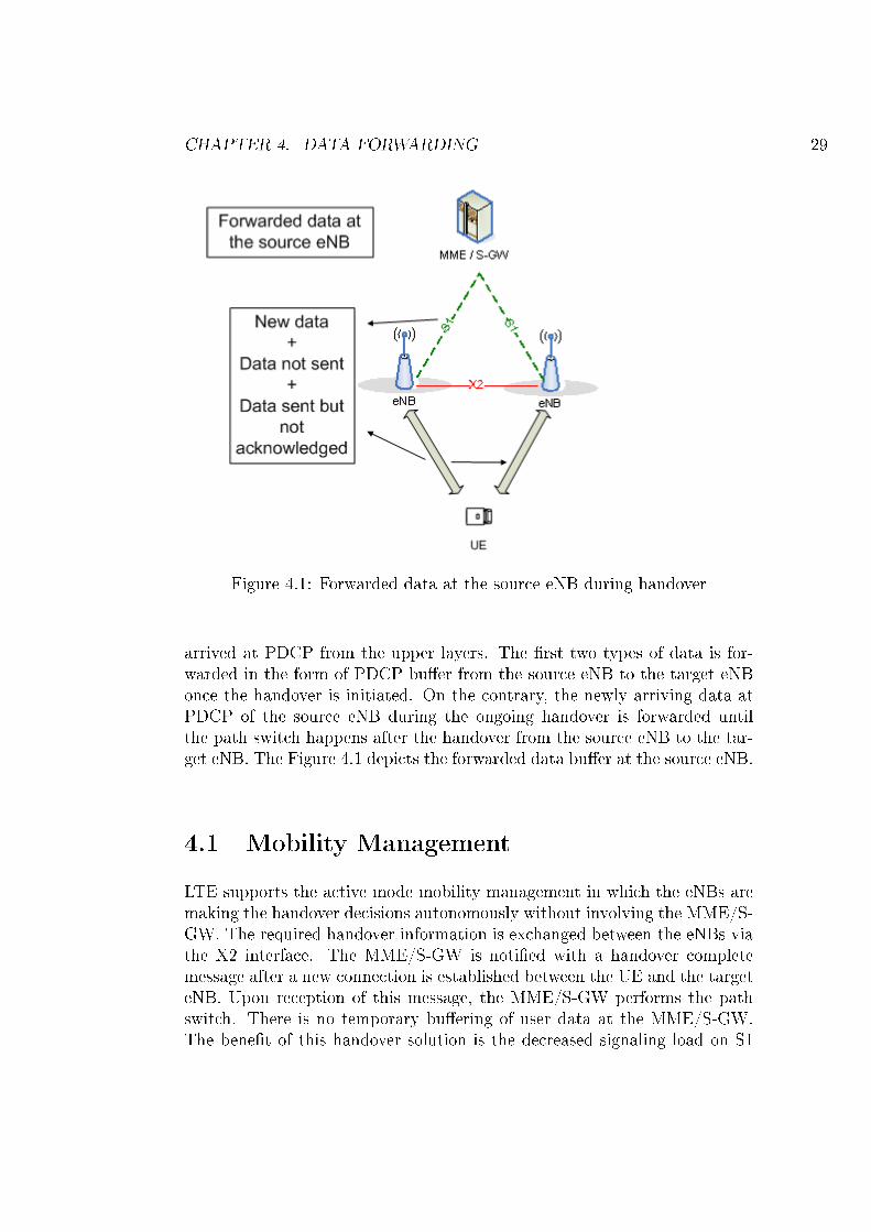
The forwarded data at the source eNB is made up of: (1) the data that isalready sent on the air but not yet acknowledged by the UE, (2) the datain the PDCP queue which is not sent yet and (3) the data that has newly
28
CHAPTER 4. DATA FORWARDING 29
Figure 4.1: Forwarded data at the source eNB during handover
arrived at PDCP from the upper layers. The �rst two types of data is for-warded in the form of PDCP bu�er from the source eNB to the target eNBonce the handover is initiated. On the contrary, the newly arriving data atPDCP of the source eNB during the ongoing handover is forwarded untilthe path switch happens after the handover from the source eNB to the tar-get eNB. The Figure 4.1 depicts the forwarded data bu�er at the source eNB.
4.1 Mobility Management
LTE supports the active mode mobility management in which the eNBs aremaking the handover decisions autonomously without involving the MME/S-GW. The required handover information is exchanged between the eNBs viathe X2 interface. The MME/S-GW is noti�ed with a handover completemessage after a new connection is established between the UE and the targeteNB. Upon reception of this message, the MME/S-GW performs the pathswitch. There is no temporary bu�ering of user data at the MME/S-GW.The bene�t of this handover solution is the decreased signaling load on S1
CHAPTER 4. DATA FORWARDING 30
Figure 4.2: Intra LTE handover with data forwarding [4]
interface. During the handover, the protocol end points that are located inthe eNBs are required to be moved from the source eNB to the target eNB.In LTE, the RLC/MAC protocols (ARQ/HARQ window states) are reset athandover.
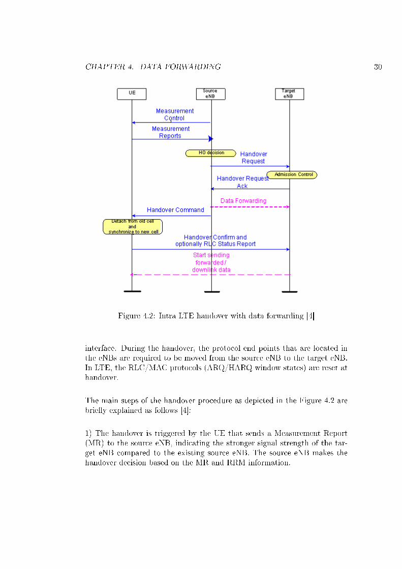
The main steps of the handover procedure as depicted in the Figure 4.2 arebrie�y explained as follows [4]:
1) The handover is triggered by the UE that sends a Measurement Report(MR) to the source eNB, indicating the stronger signal strength of the tar-get eNB compared to the existing source eNB. The source eNB makes thehandover decision based on the MR and RRM information.
CHAPTER 4. DATA FORWARDING 31
2) Handover negotiation phase starts by sending the Handover Request fromthe source eNB to the target eNB.
3) The target eNB makes the handover decision, based on the available ra-dio resources and also prepares L1/L2 for the Handover and responds to thesource eNB with the Handover Request Ackowledgement, which provides in-formation for the establishment of the new radio link. The information alsoincludes the new Cell Radio Network Temporary Identity (C-RNTI).
4) The source eNB transfers all the necessary information to the UE in theHandover Command. From this instant, the source eNB may stop sendingand receiving data over the air and it may forward the DL data to the tar-get eNB. The source eNB forwards the RLC SDUs that are bu�ered, butnot yet acknowledged. In other words, partially transmitted SDUs at theHARQ/ARQ layers will be forwarded along with the bu�ered and not yettransmitted SDUs, which also includes all the incoming SDUs from the GW.
5) The UE establishes the new radio connection to the target eNB on receiv-ing the Handover Command. This procedure involves detaching from theold cell, synchronizing to a new one, obtaining timing advance and uplinkallocation. During this time (Detach Time) there is no radio connectivityto the system. The UE sends the Handover Con�rm message informing thetarget eNB about the success of handover.
6) The target eNB initiates the data path switching by sending the Han-dover Complete to the MME/SAE Gateway. The UE location information isupdated at the MME/SAE Gateway, after receiving the Handover Completemessage and the target eNB performs the path switching, after which packetsare directly sent to the target eNB.
7) The MME/SAE Gateway con�rms the path switching with the HandoverComplete Acknowledge message. After receiving this message, the targeteNB sends the Release Resource indication to the source eNB, so that thesource eNB can �ush its forwarded DL data bu�er that might have beenstored for the case of the handover fallback.
The quality of service during the handover is based on the detach time, dur-ing which the UE is not connected to the system, the delay of the forwarded
CHAPTER 4. DATA FORWARDING 32
packets and the delay di�erence between the direct path and the forwardedpath. The goal of the thesis is to reduce the delay of the forwarded packets,by decreasing the amount of the forwarded data that is already received bythe UE. The idea is to decrease the amount of discarded DL packets both atthe target eNB and UE.
4.2 Data Forwarding Mechanism
Data forwarding is introduced in 3GPP LTE Release 8 speci�cation [4] and[25]. The speci�cation [25] covers the UE side of the protocol, however, PDCPis also used in the network side at handover to perform data forwarding be-tween the eNBs over the X2 interface. More details on the X2 messaging,such as the SN Status Transfer, are described in [28]. During the ongoinghandover, the source eNB forwards all the unacknowledged PDCP SDUs tothe target eNB. Data forwarding is also explained brie�y in [29] and [30]. [29]explains the need of packet forwarding in LTE and also shows how forward-ing helps to improve the TCP throughput. It also deals with the problemof out of order packet delivery during the handover and proposes a solu-tion to the problem. In [30], authors provide the overview of LTE, handoverprocedure and also evaluate the impact of forwarding on the user connection.
The thesis proposes various techniques to improve the packet forwardingmechanism as speci�ed in 3GPP LTE Release 8 standards by reducing thenumber of PDCP packets that are required to be forwarded from the sourceeNB to the target eNB. PDCP and RLC protocols are used to ensure thelossless handover functionality. The RB is con�gured to use the RLC proto-col in AM, and the corresponding PDCP mode for DRB. Each PDCP PDUis given to RLC for transmission. The RLC AM functions so that each RLCPDU sent out must be acknowledged by the receiver side to the transmitterside. ACKs are sent upon a POLL request from the transmitter, and upont-Reordering timer expiry at the receiver side, in case the t-StatusProhibittimer is not running and there are missing PDUs. If the t-StatusProhibit isrunning, the RLC STATUS is sent upon the expiry of the timer.
RLC entity receives the RLC SDUs from upper layer and sends RLC PDUs toits peer RLC entity via lower layers. Similarly, RLC entity delivers the RLCSDUs to upper layer and receives RLC PDUs from its peer RLC entity vialower layers. One RLC PDU can contain a various number of PDCP SDUs,
CHAPTER 4. DATA FORWARDING 33
Figure 4.3: Data forwarding during the Intra-LTE handover from the sourceeNB to the target eNB [4]
or segments thereof, based on the instantaneous link bitrate. Upon receptionof an ACK for the whole RLC SDU, the RLC protocol must indicate thesuccessful delivery of the higher layer PDU to the upper layer, i.e., to thePDCP transmitter. To ensure a lossless handover, the PDCP transmittershould not discard the SDUs from it's bu�er before PDCP has received theindication of the successful delivery from the RLC transmitter.
Below the RLC layer, the HARQ protocol at the MAC level is responsiblefor the transmission and retransmission of the packets. LTE link layer usestransmissions/retransmissions at both the MAC and RLC layer, of which, theMAC HARQ retransmissions are comparatively faster than the RLC ARQretransmissions. The HARQ is usually con�gured so that there is a highprobability of the data transmitted from the source eNB to be successfullyreceived by the UE without involving RCL retransmissions.
During the handover, all the PDCP SDUs that have not been ACKed bythe lower layer are forwarded to the target eNB from the source eNB. Thismechanism of forwarding is speci�ed in 3GPP LTE Release 8 speci�cation.The Figure 4.3 depicts the intra LTE handover between the source eNB andthe target eNB. The source eNB may start the data forwarding after it re-ceives HO request acknowledgement from the target eNB. The UE moves to
CHAPTER 4. DATA FORWARDING 34
the target eNB after receiving the handover command from the source eNB.When in the target cell, UE sends the handover con�rmation message to thetarget eNB. At this stage, UE may also transmit the PDCP Status report, ifso con�gured by the source eNB. After reception of the PDCP Status report,the target eNB can discard the PDCP SDUs that have already been receivedby the UE in the source cell. If the UE is not con�gured to transmit thePDCP Status report to the target eNB, the target eNB will transmit all thethe forwarded SDUs. The UE may drop some of these SDUs received fromthe target eNB, if the UE has already received the SDUs from the sourceeNB before the handover.
4.3 Problem with the Data Forwarding
A problem with the existing data forwarding mechanism is that the sourceeNB is unaware of the latest information, of what data the UE has receivedand what it has not received. During the handover, all the unacknowledgedPDCP SDUs are forwarded to the target eNB by the source eNB via X2interface. Many of these PDCP SDUs, that are forwarded to the target eNBhave been already successfully received at the UE, and so are either droppedat the target eNB or at the UE. This results in ine�cient data forwardingmechanism between the source eNB and the target eNB, which unnecessar-ily increases the load on the data link connecting the two eNB's and also onthe air interface between the target eNB and the UE. Since the RLC ACKprocedure depends on the POLL and the t-Reordering settings, it could bethat many of those SDUs have been already successfully delivered to the UE,and would not need to be forwarded to the target eNB.
4.4 Existing Work to Improve the Data For-
warding Mechanism
Based on the 3GPP LTE Release 8 speci�cation, all the unacknowledgedPDCP SDUs are forwarded from the source eNB to the target eNB. Oneof the 3GPP contributions [31], compares this forwarding scheme with theno-forwarding scheme, which may also be the possible implementation choicefor the deployment scenarios. In the no-forwarding scheme, the source eNBdiscards all stored PDCP SDUs. The lost PDCP SDUs will not be recovered
CHAPTER 4. DATA FORWARDING 35
by RAN protocol but by the upper layer retransmission protocol such as TCPlayer. The author concludes that the forwarding scheme of the RLC SDUs isan essential feature to guarantee the good TCP performance during the han-dover. Moreover, [31] also states that there is unnecessary data forwardingfrom the source eNB to the target eNB, due to late RLC status reporting.The 3GPP contribution recommends the need of some optimizations on thisaspect, such as the event triggered RLC status reporting at the source eNB.Several solutions to solve the problem of ine�cient data forwarding mecha-nism at hand, have been presented in the form of the 3GPP contributions,and have also been patented, such as, in [7], [32], [33] and [34]. All theserecommended solutions are further analysed in the following section.
One of the 3GPP contributions [7] proposes two solutions to improve thedata forwarding mechanism. The �rst solution is that the source eNB pollsthe UE, just after receiving the MR from the UE. But, it concludes claimingthat the time between the source eNB receives the MR, until the source eNBsends the handover command, is not always enough, to poll the peer UERLC and in return, receive the RLC status report.
As another solution, [7] and [32] both suggest to send the RLC status reportalong with the MR in the uplink. The source eNB con�gures the measure-ments in the UE, as speci�ed in [8]. It is the responsibility of the UE to sendthe MR, whenever the conditions con�gured by the source eNB is satis�ed.Based on [8], measurement events such as Event A3 (Neighbour becomes o�-set better than serving), Event A4 (Neighbour becomes better than thresh-old) and Event A5 (Serving becomes worse than threshold1 and neighbourbecomes better than threshold2) can trigger the source eNB to perform thehandover of the UE to the target eNB. During the ongoing handover, thesource eNB may also perform the data forwarding to the target eNB. As perthe solution, it suggests to send the RLC status report along with the MR,which has a higher chance of trigerring the handover between the intra LTEeNBs. The problem with the suggested solution is that MR is sent by theUE RRC, whereas RLC status report is sent by the UE RLC. It means thatwhenever the UE RRC is sending the the MR, which has a higher chance oftrigerring the handover, the UE RRC also needs to inform the UE RLC tosend the RLC status report. Presently the 3GPP LTE RRC standard [8] doesnot support such inter layer messages. Moreover, such inter layer messagesare not acknowledged as the part of the 3GPP UE standard. Lastly, thesolution will also require the new RLC status message trigger in the 3GPPRLC standards. Presently based on the 3GPP LTE RLC speci�cations [23],
CHAPTER 4. DATA FORWARDING 36
RLC is supposed to send the RLC status report only due to triggers such asthe polling from its peer AM RLC entity, detection of a missing RLC dataPDU. To sum up, the proposed solution requires changes in the 3GPP LTERelease 8 speci�cations of RRC [8] and RLC [23]. So far, the aforementionedsolution have not been accepted in the 3GPP to be part of the speci�cation.
A further solution introduced in [33], suggest to send the PDCP status re-port, instead of the RLC status report to the source eNB, before the UEdetaches from the source eNB. This solution is similar to the last solution asdiscussed above and will require changes to the 3GPP LTE Release 8 speci-�cations of RRC [8] and PDCP [25], and has so far not been accepted to bepart of the speci�cation. Lastly, a further solution proposed in [34] is similarto the one proposed in [7].
4.5 Proposed Solutions to Improve the Data
Forwarding Mechanism
During the ongoing handover, all the data present in the PDCP bu�er atthe source eNB needs to be forwarded to the target eNB. The thesis pro-poses the techniques to improve the data forwarding mechanism by reducingthe amount of data forwarding between the source eNB and the target eNB,which are as follows:
1) Change the UE polling frequency based on the downlink data rate
The proposed solution tries to decrease the data that is already sent overthe air but not yet acknowledged by the UE. Increasing the UE polling fre-quency allows the source eNB to be as up to date to the UE reception stateas possible, and thus reduces the data bu�er at the PDCP of the source eNB.
The basic idea with the suggested technique is that the source eNB will pollthe UE more often, when the UE speci�c downlink data rate is high. On thecontrary, the source eNB will poll the UE less often, during the lower down-link data rate. The proposed method minimizes the data being forwardedfrom the source eNB to the target eNB, as the source eNB will be as up todate to the UE reception state as possible, and thus reduces the number of
CHAPTER 4. DATA FORWARDING 37
unacknowledged PDCP SDUs to be forwarded to the target eNB.
There exists a tradeo� between the PDCP data forwarding bu�er size in theeNB and the uplink RLC status load. When the source eNB polls the UEmore often to decrease the PDCP bu�er size, the uplink RLC status loadincreases. Similarly, when the source eNB polls the UE less often then thePDCP bu�er size increases but the uplink RLC status load decreases.
The UE polling frequency can be changed based on the RLC con�gurationparameter of the source eNB such as the pollByte or the pollPDU. PollByteor pollPDU is used by the source eNBs transmitting side of each AM RLCentity to trigger a poll for every "pollByte" of data send or every "pollPDU"PDUs sent to the UE. Moreover, along with this parameter change, the sourceeNB should also con�gure the UEs t-StatusProhibit timer, in such a way thatit allows the UE to send the RLC status report. The t-StatusProhibit timeris used by the UEs receiving side of an AM RLC entity in order to prohibitthe transmission of the RLC STATUS PDUs.
Please note that, the proposed solution does not consider the ongoing han-dover, while changing the UE polling frequency. The problem with the pro-posed solution is that, we are increasing the UE polling frequency, eventhough there is no improvement in the data forwarding e�ciency, in the sce-narios when the handover is not ongoing. This results in higher RLC statusload in the uplink due to RLC status reports sent from the UE to the sourceeNB at all times.
2) Change the UE polling frequency during handover based on the downlinkdata rate
This solution is a slight variant from the last solution, and also tries to de-crease the data that is already sent on the air but not yet acknowledged bythe UE. It is di�erent than the last proposed solution, as the UE pollingfrequency is changed, just before the ongoing handover, based on the down-link data rate. The advantage with the solution is that it does not result tothe higher uplink RLC status load, when the handover is not ongoing. UEpolling frequency can be changed based on the RLC con�guration parameterof the eNB such as change the value of the pollByte or the pollPDU, as ex-plained in the last solution. A tradeo� between the PDCP data forwardingbu�er size in the eNB and the uplink RLC status load still exists as in case
CHAPTER 4. DATA FORWARDING 38
of the last proposed method.
3) Stop user scheduling after the MR is sent
This solution tries to decrease the data that has newly arrived at PDCP fromupper layers. Once the UE sends the MR to the source eNB, the source eNBmay decide to perform the handover to the target eNB. If the source eNB isgoing to perform the handover, then based on the suggested solution, it alsostops scheduling DRBs from that speci�c UE till the handover is performed.Please note that the SRBs of that speci�c UE may still be scheduled. In themeantime, the source eNB can also schedule the other UE's present in theexisting cell.
4) Stop downlink user scheduling and allow limited uplink user scheduling
This solution is a slight variant from the last solution, and also tries to de-crease the data that has newly arrived at PDCP from the upper layers andalso partly reduces the data that is already sent on the air but not yet ac-knowledged by the UE. It is di�erent than the last proposed solution, as thesource eNB only stops downlink DRBs user scheduling for the UE undergo-ing the handover, but allows the limited uplink user scheduling. The limiteduplink user scheduling allows the UE to send the RLC status report to thesource eNB in the uplink. On receiving the RLC status report, the sourceeNB can drop the acknowledged PDCP SDUs, and thus decrease the amountof data that needs to be forwarded to the target eNB.
Chapter 5
Simulation Results
5.1 Problem Formulation
Various data forwarding mechanisms from the source eNB to the target eNBin LTE are studied as part of the thesis. The goal is to propose and evalu-ate various techniques that reduce the data forwarding as speci�ed in 3GPPRelease 8 speci�cation. In this chapter, we will �rst introduce the systemmodel for the simulation and then present the simulation results based on theproposed techniques to improve the data forwarding during handover in LTE.
5.2 Simulation Environment and SystemModel
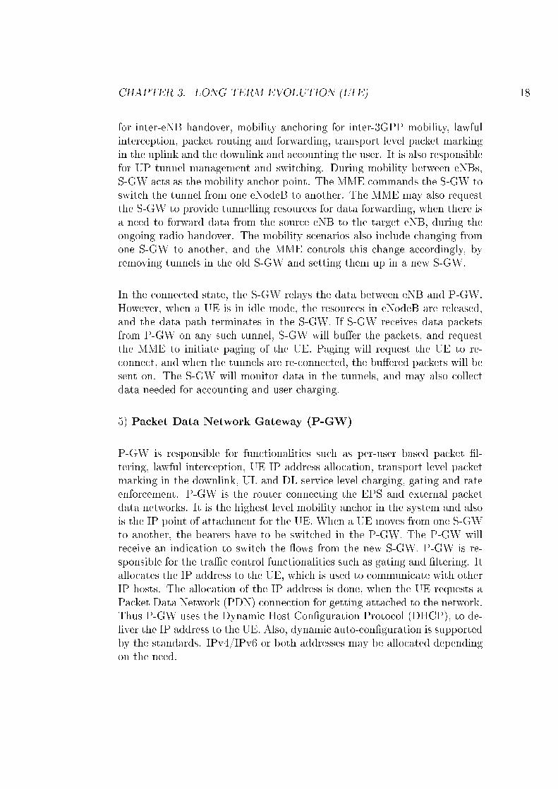
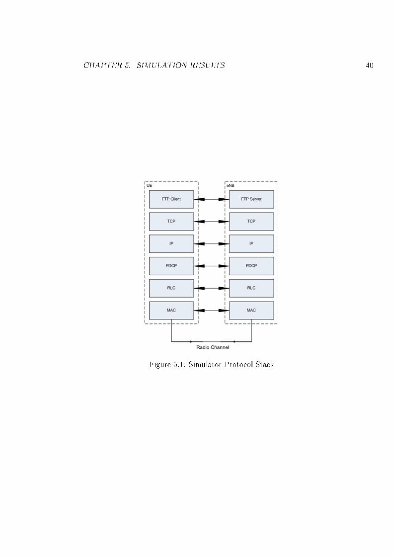
The LTE simulator developed at Ericsson Research was used in the thesis toimplement and simulate various techniques to improve the data forwardingmechanism. As shown in the Figure 5.1, simulator consist of protocol layerssuch as a FTP client/server, TCP/IP, PDCP, RLC and MAC.
The FTP client sends the FTP Request to the corresponding FTP serverand waits for the FTP response to be sent. Once, the FTP client receivesthe data from the underlying TCP layer, it schedules another request or justterminates. Note that, in our data forwarding DL simulation, the FTP clientis located in the UE, whereas as the FTP server is in the Core Network. Re-quests are always sent from the FTP client to the FTP server and the FTPreponse the other way around. The mean reading time is the time between
39
CHAPTER 5. SIMULATION RESULTS 40
Figure 5.1: Simulator Protocol Stack
CHAPTER 5. SIMULATION RESULTS 41
two consecutive FTP requests, which is �xed in the simulations. Object bitrate is calculated based on the data rate which the FTP client experiences.
The TCP provides reliable data transfer between two the TCP entities bymeans of an ARQ protocol. Furthermore, TCP performs congestion controlto avoid overloading underlying links. TCP is connected to an underlying IPentity, and to the FTP client/server in the upper layer.
The IP layer accepts data from a higher layer, encapsulates it into IP pack-ets and forwards it to the lower layer. The peer IP entity receives theseIP packets, extracts the payload and forwards the packet to the TCP layer.Functionality of PDCP, RLC and MAC layers are already explained earlierin the the chapter "Long Term Evolution".
The simulator is run in a simpli�ed mode, which does not include the phys-ical layer functionality of the adaptive modulation and coding (AMC), i.e.the modulation rate is not changed based on the UE experienced radio con-ditions. The scope of the thesis is to decrease the amount of data forwardingwhich is the responsibility of PDCP, so not including the AMC functionalityis a fair assumption. The transport format size is selected randomly, howevergiving a mean downlink data rate of 75 Mbits per sec.
The system is being modelled for a single user, who does a FTP download ofa 100 MB �le, 50 times, while being connected to the eNB. The simulationis controlled in such a way that, although the UE is static, the handoveroccurs every 4 s. Data is required to be forwarded from the source eNB tothe target eNB during the ongoing handover. The RLC mechanism is basedon the polling con�guration parameter pollByte, having the value of 3000KB. The used tra�c model is FTP with a �xed �le size. The FTP tra�cmodel is supposed to give the most data forwarding gain compared to othertra�c models like web browsing.
The parameters used in the simulation, which are de�ned in [4] [6] [23] areas shown in the Table 5.1.
1) Transmit time interval (TTI) refers to the length of an independentlydecodable transmission on the radio link, which is 1 ms in LTE.
2) Measurement report delay is the assumed �xed delay in the simulation
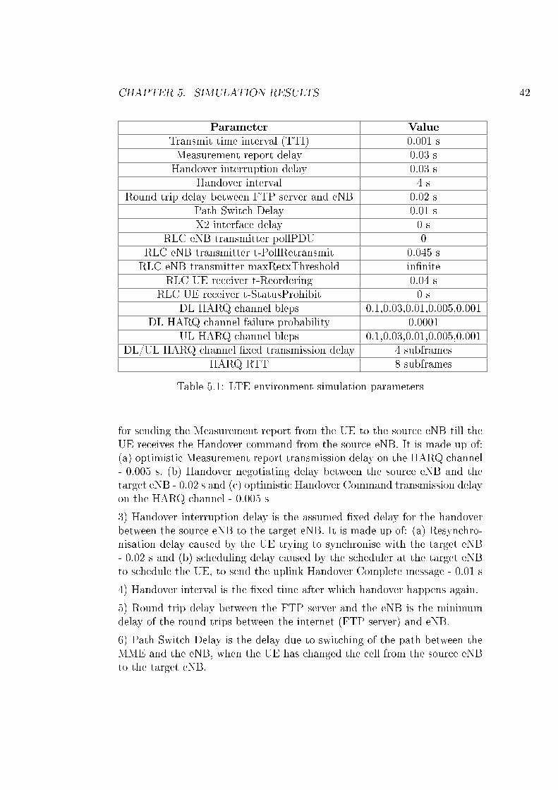
CHAPTER 5. SIMULATION RESULTS 42
Parameter ValueTransmit time interval (TTI) 0.001 sMeasurement report delay 0.03 sHandover interruption delay 0.03 s
Handover interval 4 sRound trip delay between FTP server and eNB 0.02 s
Path Switch Delay 0.01 sX2 interface delay 0 s
RLC eNB transmitter pollPDU 0RLC eNB transmitter t-PollRetransmit 0.045 sRLC eNB transmitter maxRetxThreshold in�nite
RLC UE receiver t-Reordering 0.04 sRLC UE receiver t-StatusProhibit 0 s
DL HARQ channel bleps 0.1,0.03,0.01,0.005,0.001DL HARQ channel failure probability 0.0001
UL HARQ channel bleps 0.1,0.03,0.01,0.005,0.001DL/UL HARQ channel �xed transmission delay 4 subframes
HARQ RTT 8 subframes
Table 5.1: LTE environment simulation parameters
for sending the Measurement report from the UE to the source eNB till theUE receives the Handover command from the source eNB. It is made up of:(a) optimistic Measurement report transmission delay on the HARQ channel- 0.005 s, (b) Handover negotiating delay between the source eNB and thetarget eNB - 0.02 s and (c) optimistic Handover Command transmission delayon the HARQ channel - 0.005 s
3) Handover interruption delay is the assumed �xed delay for the handoverbetween the source eNB to the target eNB. It is made up of: (a) Resynchro-nisation delay caused by the UE trying to synchronise with the target eNB- 0.02 s and (b) scheduling delay caused by the scheduler at the target eNBto schedule the UE, to send the uplink Handover Complete message - 0.01 s
4) Handover interval is the �xed time after which handover happens again.
5) Round trip delay between the FTP server and the eNB is the minimumdelay of the round trips between the internet (FTP server) and eNB.
6) Path Switch Delay is the delay due to switching of the path between theMME and the eNB, when the UE has changed the cell from the source eNBto the target eNB.
CHAPTER 5. SIMULATION RESULTS 43
7) X2 interface delay is the delay caused while forwarding the data betweenthe two eNBs during the handover.
8) RLC eNB transmitter pollPDU is used by the eNB's transmitting side ofeach AM RLC entity to trigger the poll for every "pollPDU" PDUs.
9) RLC eNB transmitter t-PollRetransmit is used by the eNB's transmittingside of each AM RLC entity to retransmit the poll, if the UE does notrespond.
10) RLC eNB transmitter maxRetxThreshold is used by the eNB's transmit-ting side of each AM RLC entity to limit the number of retransmissions ofan AMD PDU.
11) RLC UE receiver t-Reordering timer is used by the UE's receiving sideof an AM RLC entity in order to detect the loss of the RLC PDUs at thelower layer. If t-Reordering is running, t-Reordering shall not be startedadditionally, i.e. only one t-Reordering per RLC entity is running at thegiven time.
12) RLC UE receiver t-StatusProhibit timer is used by the UE's receiving sideof an AM RLC entity in order to prohibit the transmission of the STATUSPDU.
13) DL/UL HARQ channel bleps is the block error probabilities for theHARQ transmission attempts.
14) DL HARQ channel failure probability is the probability that the trans-mission attempt results in the HARQ failure, i.e., in the packet loss. Thismay e.g. be due to a NACK=>ACK error.
15) DL/UL HARQ channel �xed transmission delay is the minimum trans-mission delay experienced by all DataUnits. An additional variable delay isadded based on the simulated number of HARQ transmission attempts.
16) HARQ RTT is the round trip delay time on the HARQ channel.
5.3 Simulation Results
3GPP LTE Release 8 speci�cation [4] speci�es the forwarding mechanism forhandling the packet forwarding during the handover. Accordingly, all thePDCP SDUs that have not been ACKed by the lower layer are forwardedto the target eNB from the source eNB. In our simulations, the source eNBpolls the UE at a constant rate, irrespective of the ongoing handover scenar-
CHAPTER 5. SIMULATION RESULTS 44
ios. This mechanism is taken as a base method to compare the performancewith the technique proposed in [7] and other techniques proposed as a partof the thesis. The performance criteria is based on the PDCP bu�er sizerequired for the data forwarding, user experienced object bitrate and uplinkRLC status load. The techniques that are implemented in the LTE simulatorare as shown below:
1) Reference case in which no RLC report is sent with the MR and the UEpolling frequency is kept constant
2) Send the RLC status report along with the MR [7]
3) Change the UE polling frequency based on the downlink data rate
4) Change the UE polling frequency during handover based on the downlinkdata rate
5) Stop user scheduling after MR is sent
6) Stop downlink user scheduling and allow limited uplink user scheduling
The value of pollByte is kept constant to 3000 KB in the above mentionedtechniques such as: (1) reference case, (2) Send the RLC status report alongwith the MR, (3) Stop user scheduling after MR is sent and (4) Stop down-link user scheduling and allow limited uplink user scheduling.
Whereas, the value of pollByte is 280 KB in case of the proposed methodson "Change the UE polling frequency based on the downlink data rate".Moreover, the value of pollByte varies based on the handover in case of theproposed technique "Change the UE polling frequency during handover basedon the downlink data rate". The value of pollByte is 3000 KB, when the han-dover is not ongoing. On the contrary, the value of pollByte is decreased to280 KB, when the handover is ongoing.
The AM RLC entity of the source eNB triggers a poll for every "pollByte"of the data transmitted to the UE. The value of pollByte is derived based onthe downlink data rate (75 Mbps) and period (0.03 sec), as shown below:
CHAPTER 5. SIMULATION RESULTS 45
pollByte = Data Rate * Period
where, period (0.03 s) is the Measurement report delay that is the time be-tween the UE sends the MR to the source eNB to the time UE receivesHandover Command from the source eNB.
As shown in the Figure 5.2, the proposed method on "Change the UE pollingfrequency based on the downlink data rate" performs not only better thanthe reference case but also better than the method on "Send the RLC statusreport along with the MR" proposed in [7]. It reduces the amount of dataforwarding at the PDCP source eNB by nearly 50% compared to the referencecase, in which UE is polled with the constant polling frequency.
In [7], author claims that the time between the source eNB receives the MR,until the source eNB sends the handover command, is not always enough, topoll the peer UE RLC and in return, receive the RLC status report. However,based on the simulation performed using the similar parameters in the LTEsimulator, the thesis proposes that the time between the source eNB receivesthe MR, until the source eNB sends the handover command, is enough topoll the peer UE RLC and in return receive the RLC status report. Basedon the results, the thesis proposes the technique of increasing the UE pollingfrequency during the ongoing handover, compared to the time when the han-dover is not ongoing. Simulation results prove that the proposed methodgives better performance in terms of more e�cient data forwarding mecha-nism compared to the one proposed in [7].
As a part of the performed simulations, the RLC pollByte is changed basedon the downlink data rate. The value of the pollByte parameter is decreasedwhen the UE has a higher downlink data rate, whereas, the value of the poll-Byte parameter is increased when the UE has a lower downlink data rate. Asthe value of the pollByte is decreased when the UE has a higher data rate,the polling will be performed more often, and in turn the UE will respondwith RLC status reports more often. As a result, the source eNB is updatedwith the more precise UE reception state. Thereby, decreasing the amountof data required to be forwarded from the source eNB to the target eNB.Similarly, when the UE is experiencing lower data rate, the value of pollByteis increased, resulting in fewer RLC status reports from the UE to the sourceeNB. The source eNB does not need to poll the UE more often during thelower downlink data rate as the PDCP bu�er size is already smaller in the
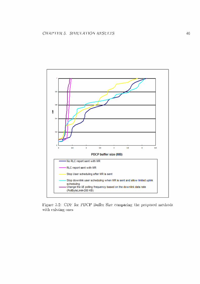
CHAPTER 5. SIMULATION RESULTS 46
Figure 5.2: CDF for PDCP Bu�er Size comparing the proposed methodswith existing ones
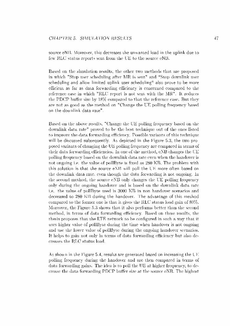
CHAPTER 5. SIMULATION RESULTS 47
source eNB. Moreover, this decreases the unwanted load in the uplink due tofew RLC status reports sent from the UE to the source eNB.
Based on the simulation results, the other two methods that are proposedin which "Stop user scheduling after MR is sent" and "Stop downlink userscheduling and allow limited uplink user scheduling" also prove to be moree�cient as far as data forwarding e�ciency is concerned compared to thereference case in which "RLC report is not sent with the MR". It reducesthe PDCP bu�er size by 18% compared to that the reference case. But theyare not as good as the method on "Change the UE polling frequency basedon the downlink data rate".
Based on the above results, "Change the UE polling frequency based on thedownlink data rate" proved to be the best technique out of the ones listedto improve the data forwarding e�ciency. Possible variants of this techniquewill be discussed subsequently. As depicted in the Figure 5.3, the two pro-posed variants of changing the UE polling frequency are compared in terms oftheir data forwarding e�ciencies. In one of the method, eNB changes the UEpolling frequency based on the downlink data rate even when the handover isnot ongoing i.e. the value of pollByte is �xed as 280 KB. The problem withthis solution is that the source eNB will poll the UE more often based onthe downlink data rate, even though the data forwarding is not ongoing. Inthe second method, the source eNB only changes the UE polling frequencyonly during the ongoing handover and is based on the downlink data ratei.e. the value of pollByte used is 3000 KB in non handover scenarios anddecreased to 280 KB during the handover. The advantage of this methodcompared to the former one is that it gives the RLC status load gain of 80%.Moreover, the Figure 5.3 shows that it also performs better than the secondmethod, in terms of data forwarding e�ciency. Based on these results, thethesis proposes that the LTE network to be con�gured in such a way that ituses higher value of pollByte during the time when handover is not ongoingand use the lower value of pollByte during the ongoing handover scenarios.It helps to gain not only in terms of data forwarding e�ciency but also de-creases the RLC status load.
As shown in the Figure 5.4, results are generated based on increasing the UEpolling frequency during the handover and are then compared in terms ofdata forwarding gains. The idea is to poll the UE at higher frequency, to de-crease the data forwarding PDCP bu�er size at the source eNB. The highest
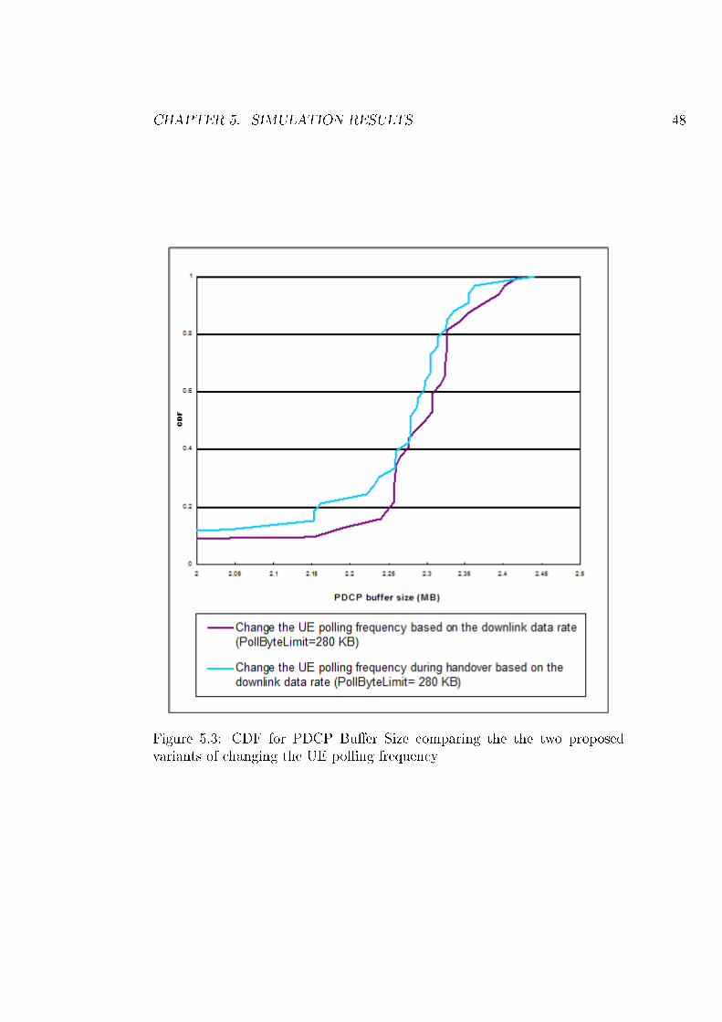
CHAPTER 5. SIMULATION RESULTS 48
Figure 5.3: CDF for PDCP Bu�er Size comparing the the two proposedvariants of changing the UE polling frequency
CHAPTER 5. SIMULATION RESULTS 49
Figure 5.4: CDF for PDCP Bu�er Size based on increasing the UE pollingfrequency
CHAPTER 5. SIMULATION RESULTS 50
data forwarding gain is achieved in case of "Change the UE polling frequencyduring handover based on downlink data rate (PollByteLimit=1000 Bytes)".It maps to polling the UE every TTI during the ongoing handover scenarios.In this method, the achieved gain in terms of the reduced PDCP bu�er sizeat the source eNB, during the data forwarding is around 7% compared to themethod in which PollByteLimit is 280KB, and is set based on the downlinkdata rate during handover. But the problem with this method is it increasesthe RLC status load by 21%. The gain of increasing the polling frequencyduring the handover is to reduce the data forwarding PDCP bu�er size atthe source eNB, but the problem with increasing the polling frequency isthe increase in the higher RLC status load due to more RLC Status reportssent from the UE to the source eNB. To sum up, the thesis recommends theLTE network to use the optmised value of pollByte, as there exist a tradeo�between the PDCP data forwarding bu�er size in the eNB and the uplinkRLC status load.
All the proposed data forwarding techniques were compared with the refer-ence case data forwarding technique in terms of the data forwarding PDCPbu�er size gain and RLC status load in the uplink. The proposed techniquesshall also be compared to the reference case data forwarding technique interms of user experienced object bit rate. Higher object bit rate in�uencethe better end user experience. The Figure 5.5 compares the object bit ratesof all the techniques, and the proposed technique of "Change the UE pollingfrequency based on the downlink data rate" gave the best object bit rate.It gave better results by around 2% higher object bitrate compared to thereference data forwarding mechanism.
Various techniques of data forwarding were compared in terms PDCP bu�ersize at the source eNB, uplink RLC status load and user object bit rate.Based on the above results to improve the data forwarding mechanism in theLTE Release 8 networks, the thesis recommends the LTE network to poll theUE more frequently during the ongoing handover scenarios, compared to thecase when handover is not ongoing. Based on the simulation results, thisproposed technique proves to be the most e�cient in terms of lower PDCPbu�er size at the source eNB, lower uplink RLC status load and higher userobject bit rate. The thesis also recommends the LTE network to use theoptimised value of pollByte. Network designer may consider the tradeo� be-tween the PDCP data forwarding bu�er size in the eNB and the uplink RLCstatus load, while determining the value of the pollByte.
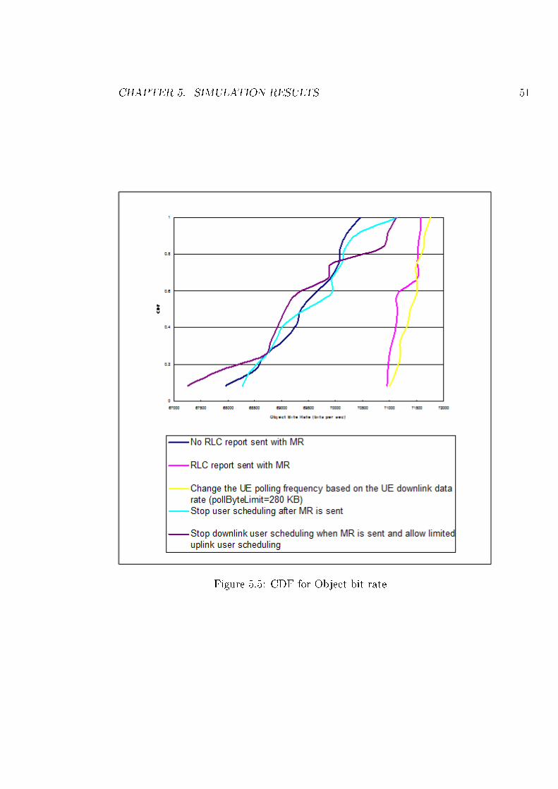
CHAPTER 5. SIMULATION RESULTS 51
Figure 5.5: CDF for Object bit rate
Chapter 6
Conclusion
At handover between the base stations in LTE, data is forwarded from thesource eNB to the target eNB. The mechanism for handling the packet for-warding is speci�ed in the 3GPP LTE Release 8 speci�cations. Various tech-niques are proposed and also evaluated to improve the packet forwardingmechanism during the handover by reducing the amount of forwarded datain the downlink. Performance criteria considered for evaluating these tech-niques include the PDCP bu�er size at the source eNB, uplink RLC statusload and user object bit rate.
The thesis recommends the LTE network to poll the UE more frequentlyduring the ongoing handover scenarios, compared to the case when handoveris not ongoing. Based on the simulation results, this proposed techniqueproves to be the most e�cient in terms of lower PDCP bu�er size at thesource eNB, lower uplink RLC status load and higher user object bit rate.The thesis also recommends the LTE network to use the optimised valueof pollByte. Network designer may consider the tradeo� between the PDCPdata forwarding bu�er size in the eNB and the uplink RLC status load, whiledetermining the value of the pollByte.
52
Chapter 7
Future Work
The LTE network behaviour for the downlink data transmission during theongoing handover was studied as a part of the thesis. In the future, it wouldalso be good to study the LTE UE behaviour for the uplink data transmis-sion during the ongoing handover. UE is repsonsible for the retransmissionsof data that is not acknowledged by the source eNB to the target eNB in theuplink. It would be interesting to study and verify whether the same kind oftechniques can be applied for uplink as used in case of downlink to improvethe packet retransmission e�ciency. This may reduce the PDCP bu�er sizeduring the ongoing handover at the UE, resulting in less data required tobe retransmitted to the target eNB. The applied technique may reduce theradio channel uplink load between the UE and the target eNB.
The simulator is presently run in a simpli�ed mode, which does not includethe physical layer functionality of AMC. UE experiences the mean downlinkdata rate as 75 Mbits per sec. In future, it would be good to include thephysical layer, which changes the modulation and coding at the eNB basedon the CQI reported by the UE.
53
Bibliography
[1] Ericsson. LTE - an introduction. Jun, 2009. http://www.ericsson.
com/technology/whitepapers/lte_overview.pdf.
[2] David Astely, Erik Dahlman, Anders Furuskär, Ylva Jading, MagnusLindstöm, and Stefan Parkvall; Ericsson Research. LTE: the evolutionof mobile broadband. IEEE Communications Magazine, LTE Part 2,
Radio Access Integrated Circuits for Communications Design and Im-
plementation, 47(4):44�51, Apr, 2009.
[3] Anna Larmo, Magnus Lindström, Michael Meyer, Ghyslain Pelletier,Johan Torsner, and Henning Wiemann; Ericsson Research. The LTElink-layer design. IEEE Communications Magazine, LTE Part 2, Radio
Access Integrated Circuits for Communications Design and Implemen-
tation, 47(4):52�59, Apr, 2009.
[4] 3GPP. TS 36.300 Evolved Universal Terrestrial Radio Access (E-UTRA)and Evolved Universal Terrestrial Radio Access Network (E-UTRAN);Overall description. Jun, 2009.
[5] 3GPP. TS 36.401 Evolved Universal Terrestrial Radio Access Network;Architecture description. Jun, 2009.
[6] 3GPP. TS 36.321 Medium Access Control (MAC) protocol speci�cation.Jun, 2009.
[7] Samsung. 3GPP R2-084451 RLC Status reporting during handover.Aug, 2008. http://ftp.3gpp.org/ftp/tsg_ran/WG2_RL2/TSGR2_63/
Docs/R2-084451.zip.
[8] 3GPP. TS 36.331 Radio Resource Control (RRC) protocol speci�cation.Jun, 2009.
54
BIBLIOGRAPHY 55
[9] Erik Dahlman, Stefan Parkvall, Johan Skold, and Per Beming. 3G Evo-
lution: HSPA and LTE for Mobile Broadband, Second Edition. AcademicPress, 2008.
[10] Julius Robson; Nortel and LSTI. The LTE/SAE Trial Initiative: TakingLTE/SAE from Speci�cation to Rollout. IEEE Communications Maga-
zine, LTE Part 2, Radio Access Integrated Circuits for Communications
Design and Implementation, 47(4):82�88, Apr, 2009.
[11] Long Term Evolution (LTE): Overview of LTE Air-Interface. Technicalreport, Motorola, 2007.
[12] Anssi Hoikkanen. A Techno-Economic Analysis of 3G Long-Term Evo-lution for Broadband Access. Telecommunication Techno-Economics,pages 1�7, Jun, 2007.
[13] Requirements for Evolved UTRA (E-UTRA) and Evolved UTRAN (EU-TRAN). Technical report, 3GPP, Dec, 2008.
[14] 3GPP. TS 36.201 LTE Physical Layer - General Description (Release8). Mar, 2009.
[15] Harri Holma and Antti Toskala. LTE for UMTS OFDMA and SC-
FDMA Based Radio Access. Wiley, 2009.
[16] Danish Aziz and Rolf Sigle; Alcatel-Lucent Bell Labs. Improvement ofLTE Handover Performance through Interference Coordination. Vehic-ular Technology Conference, pages 1�5, Apr, 2009.
[17] Anders Furuskar, Tomas Jonsson, and Magnus Lundevall; Ericsson Re-search. The LTE Radio Interface - Key Characteristics and Performance.Personal, Indoor and Mobile Radio Communications, pages 1 � 5, Sep,2008.
[18] Suk-Bok Lee, Sayantan Choudhury, Ahmad Khoshnevis, Shugong Xu,and Songwu Lu. Downlink MIMO with Frequency-Domain PacketScheduling for 3GPP LTE. INFOCOM 2009. The 28th Conference on
Computer Communications, pages 1269 � 1277, Apr, 2009.
[19] Christoph Spiegel, Jens Berkmann, Zijian Bai1, Tobias Scholand, Chris-tian Drewes, Guido H. Bruck, Bertram Gunzelmann, and Peter Jung.MIMO Schemes In UTRA LTE, A Comparison. Vehicular Technology
Conference, pages 2228 � 2232, May, 2008.
BIBLIOGRAPHY 56
[20] 3GPP. TS 23.101 Universal Mobile Telecommunications System(UMTS) architecture (Release 8). Dec, 2008.
[21] Kian Chung Beh, Angela Doufexi, and Simon Armour. PerformanceEvaluation of Hybrid ARQ Schemes of 3GPP LTE OFDMA System.Personal, Indoor and Mobile Radio Communications, pages 1 � 5, Sep,2007.
[22] 3GPP. TS 25.321 Medium Access Control (MAC) protocol speci�cation.Jun, 2009.
[23] 3GPP. TS 36.322 Radio Link Control (RLC) protocol speci�cation. Jun,2009.
[24] Michael Meyer, Henning Wiemann, Mats Sagfors, Johan Torsner, andJung-Fu Cheng; Ericsson Research. ARQ Concept for the UMTS Long-Term Evolution. Vehicular Technology Conference, pages 1 � 5, Sep,2006.
[25] 3GPP. TS 36.323 Packet Data Convergence Protocol (PDCP) speci�-cation. Jun, 2009.
[26] 3GPP. TS 25.323 Packet Data Convergence Protocol (PDCP) speci�-cation. Jun, 2009.
[27] Lei Zhou, Haibo Xu, Hui Tian, Youjun Gao, Lei Du, and Lan Chen.Performance Analysis of Power Saving Mechanism with Adjustable DRXCycles in 3GPP LTE. Vehicular Technology Conference, pages 1 � 5,Sep, 2008.
[28] 3GPP. TS 36.423 Evolved Universal Terrestrial Radio Access Network(E-UTRAN); X2 application protocol (X2AP) (Release 8) . Mar, 2009.
[29] Andras Racz, Andras Temesvary, and Norbert Reider; Ericsson Re-search. Handover Performance in 3GPP Long Term Evolution (LTE)Systems. IEEE, Mobile and Wireless Communications Summit, Jul,2007.
[30] Lajos Bajzik, Péter Horváth, László Krössy, and Csaba Vulkán;Nokia Siemens Networks. Impact of Intra-LTE Handover with Forward-ing on the User Connections. IEEE, Mobile and Wireless Communica-
tions Summit, Jul, 2007.
BIBLIOGRAPHY 57
[31] NEC. 3GPP R2-073070 Simulation results on downlink data forward-ing. Aug, 2007. http://ftp.3gpp.org/tsg_ran/WG2_RL2/TSGR2_59/
Docs/DocumentList.htm.
[32] Kim Soeng-Hun, Jeong Kyeong-In, Van Lieshout Gert Jan, and VanDer Velde Himke. Handover Method and Apparatus in a Mobile Commu-nication System. Samsung, Mar, 2008. http://www.wipo.int/pctdb/en/wo.jsp?IA=KR2007004599&WO=2008035935&DISPLAY=STATUS.
[33] Chaponniere Etienne F and Ho Saiyiu D. Methods and Apparatusfor Transferring a Mobile Device from a source eNB to a target eNB.Qualcomm, Jun, 2008. http://www.wipo.int/pctdb/en/wo.jsp?WO=
2008070668.
[34] Ramanuja Vedantham, Shantanu Kangude, Sandeep Bhadra, andSeung Baek. Radio Bearer Dependent Forwarding For Handover.Texas Instruments, Feb, 2009. http://www.freshpatents.com/
-dt20090212ptan20090042573.php.


![Ccna2 Chapter1 Introduction to Routing and Packet Forwarding[1]](https://img.pdfslide.us/doc/110x75/577d2fdd1a28ab4e1eb2e819/ccna2-chapter1-introduction-to-routing-and-packet-forwarding1.jpg)
![[eBook] Intro to Routing & Packet Forwarding Packet 2](https://img.pdfslide.us/doc/110x75/55cf945a550346f57ba17405/ebook-intro-to-routing-packet-forwarding-packet-2.jpg)