Embed Size (px)
Citation preview

Performance Analysis and Control Simulation of Pneumatic Liquid Online Automatic Balancing System for Rotating Machinery
Pan Xin, Wu Hai-qi, Gao Jin-ji, Mu Yu-zhe
Beijing Key Laboratory of Health Monitoring and Self-recovery for High-end Mechanical Equipment Beijing University of Chemical Technology
P.O.Box.No.130, 15 Beisanhuan East Road, Chaoyang District, Beijing 100029 P.R.China
[email protected] Abstract: - Online automatic balancing is considered to be the best solution to reduce unbalance vibrations of rotating machinery. The pneumatic liquid online automatic balancing device presented in this paper is a new type of liquid balancers, including a sealed balancing disc rotating with rotor and an air distributor mated with the balancing disc. Balancing liquid is transferred between opposite chambers by compressed air and a correcting mass is formed to balance the detected device through the change of liquid distribution in balancing disc. For a horizontal experimental installation, several performance parameters of the balancing device were analyzed, such as the volume of balancing liquid, the maximum of balancing ability and the liquid flow velocity in the connecting tube. A simulation model of the balancing device was also built using Labview virtual instrument platform and its parameters were set in accordance with the experimental device. A one by one chamber trial algorithm and a target vector algorithm were used to simulate in the model. The simulation results demonstrated that both of the two algorithms could reduce the unbalance vibrations efficiently by choosing appropriate control parameters although the liquid flow rate of balancing device was a variable value, and the target vector algorithm had a faster balancing speed and avoided the misadjustment phenomenon during the balancing process. Key-Words: - Rotating machinery; Unbalance vibration; Automatic balancing; Pneumatic liquid; Control simulation; Performance analysis
1 Introduction In the modern industry, the working speeds of rotating machinery are getting higher and higher to improve the production efficiency. The centrifugal force generated by unbalance mass is proportional to the square of rotating speed. In these high-speed occasions, a tiny unbalance mass will generate a huge unbalance force and vibration, and then affect the normal operation of the rotating devices. Therefore, the speedup of rotating machinery needs a further increase in the dynamic balance quality.
Many researches about dynamic balancing technology have been done in the last few years. These researches can be divided into two broad categories: one is about the offline dynamic balancing [1-3], and the other is about the online automatic balancing. Because the online automatic balancing can reduce the unbalance vibration of the detected rotor automatically without stop the machine, it is always considered to be the best solution to reduce unbalance vibrations of rotating machinery. Due to the different structures of the balancing actuator, the online automatic balancing technology could still be further divided into several
categories, such as ball balancer [4], hydraulic balancer [5], electro mechanical balancer [6-8], electromagnetic ring balancer [9-11] and liquid balancer [12-15]. Because the last three types of balancers need the active control during the balancing process, they are also called as the active balancing devices.
For the active balancing devices, the control algorithm has great influence on the balancing speed and balancing quality, so the research about control algorithm plays an important role in the overall study of the active balancing system. Many researches have been done to different control algorithms [16-19]. But for balancing devices, the common control algorithm includes optimizing control method and influence coefficient method. For the electromagnetic and electromagnetic ring balancers, the optimizing control method does not need to measure the absolute phase of unbalance vibration, but the relative phase between the counterweight and the rotor is needed. During the optimizing process, a phase optimization and an amplitude optimization which are done in sequence form a control cycle. After several control cycles,
WSEAS TRANSACTIONS on SYSTEMS Pan Xin, Wu Hai-Qi, Gao Jin-Ji, Mu Yu-Zhe
E-ISSN: 2224-2678 286 Volume 14, 2015

the vibration amplitude will be reduced to below the limiting value [20-21]. For the liquid balancers, the optimizing process is simplified, that is, only the several liquid chambers are needed to test in sequence, so the method is also called as a one by one chamber trial algorithm [22-23]. The trial algorithm does not need to measure the absolute phase of unbalance vibration and any other relative phase, so the corresponding control program is much simpler. The optimizing control method gets a wide range of applications in the current active balancing products, but the method cannot avoid the misadjustment of unbalance phase and the overshoot of vibration amplitude during the trial process. If the trial amount is too small, a wrong conclusion may be drawn under the disturbance of noisy signals, but if the trial amount is too big, the overshoot of vibration amplitude will be caused which is quite dangerous when initial vibration is large. The trial process also wastes a lot of time and extends the balancing time.
Compared with the optimizing control method, the operating conditions of influence coefficient method are much more, that is, the amplitude and phase of the unbalance vibration must be detected at the same time, and the influence coefficient and lag angle of the detected equipment must be known before automatic balancing. Although the influence coefficient method needs many operation conditions to carry out, the control commands of the method has a clear direction and amplitude as a targeting shooting, the method avoids the misadjustment and overshoot phenomenon, and its control process is
also much faster than the optimizing control method [24-27].
In this study, we proposed a new type of pneumatic liquid online active balancing device [28-30], analyzed the performance parameters of the device, built a simulation model for such device, and compared the control results of the one by one chamber trial algorithm and the target vector algorithm through the model. The simulation results verified the effectiveness of such two algorithms on the balancing device and provided several reference values for the control parameters in the practical applications.
2 Work principle Pneumatic liquid online automatic balancer presented in this paper is one type of the liquid- transfer balancing devices for rotating machinery. For such balancer, a balancing disc divided into four annular chambers is needed to mount on the rotor of the rotating machinery. Before installation, a certain amount of balancing liquid has already been injected into the liquid chambers. During the balancing process, compressed air is used to drive the controllable flow of balancing liquid between two opposite chambers. The mass distribution of balancing liquid in balancing disc is online changed to form a correction mass which has the same amplitude and opposite phase with the initial unbalance, and the online active balancing of the detected rotor is finished without stop the detected equipment.
Fig.1 Experimental setup of the balancing system
Balancing disc
C
A
C
B
C
C
C
D
Air distributor
Control unit
Solenoid valves
Air source
Balancing device
Displacement sensor
Air pipelines Speed sensor
Balancing disc
WSEAS TRANSACTIONS on SYSTEMS Pan Xin, Wu Hai-Qi, Gao Jin-Ji, Mu Yu-Zhe
E-ISSN: 2224-2678 287 Volume 14, 2015
The experimental setup of the balancing system
is shown in Fig.1, and its working principle is as follows: a displacement sensor and a speed sensor are fitted above the rotor to detect the amplitude and phase of unbalance vibration; only when the synchronous vibration amplitude is higher than the limiting value, the control unit starts working; according to these two parameters, the control unit determines the correction weight of rotor and sends control commands to the solenoid valves in valve block; compressed air is then led to the required chamber by the gas channels in the device, and the liquid in corresponding chamber is driven to its opposite chamber; through the liquid transfer between opposite chambers, the liquid distribution is changed and a compensation weight is produced to balance the rotor. In the balancing system, an air compressor is needed to work as air source. An air filter and a pressure reducing valve are also needed to adjust the compressed air.
3 Performance analysis 3.1 Liquid volume and balancing ability
a) Whole shape of the four liquid chambers
b) Analysis for a single liquid chamber
1 2'1
R Inner radius of liquid chamber R Outer radius of liquid chamberCentral angle of liquid chamber R Inner radius of liquid ringt Thickness of support plate r Radius of liquid ring element
: ; : ;: ; : ;
: ; : ;dr Width of liquid ring element d Angle of liquid ring element: ; : .
Fig.2 Structure chart of liquid chambers Shown in Fig. 2(a), the balancing disc of the
pneumatic liquid active balancing system is comprised by two pairs of centrosymmetric annular liquid chambers, and in the middle of each liquid
chamber is an air tube used to inject compressed air to the corresponding chamber. Before installation, the same amount of balancing liquid has already been injected into these chambers. When the balancing disc is rotating with the detected rotor, the balancing liquid in the chambers is forced to move outward under centrifugal force and forms a liquid ring along the outer wall of the chambers. The liquid ring for one annular chamber is shown in Fig. 2(b). A liquid ring element is analyzed and its area dS can be expressed by
dS rd dr rdr d (1)
So the total area cS of the liquid chamber is given
by 2 22 1
1 ( )2c
S
S rdrd R R (2)
Affected by the support plate between two liquid chambers, the actual area of one liquid
chamber aS should be the total area minus two
symmetrical rectangle areas, that is
2 22 1 2 1
12 ( ) 2 ( )
2a cS S S = R R t R R (3)
The thickness of the liquid chamber is expressed by B and the parameters of the experimental chambers are listed in Table 1, so the actual volume of one single liquid chamber can be calculated by
67.7( )aV S B ml (4)
Table 1 Parameters of liquid chamber
Items Values
Outer radius of liquid chamber 44.5 mm
Inner radius of liquid chamber 20.5 mm
Thickness of liquid chamber 62 mm
Central angle of liquid chamber 90 degree
Density of balancing liquid 1 g/ml
In order to avoid the mixture of liquid and gas
during the gas injection process which can cause the instability of liquid ring, and to avoid the leakage of balancing liquid through the gas injection tube after the devices stop running which can cause the loss of balancing liquid, the maximum of liquid volume for one single chamber cannot exceed a half of the actual volume of the chamber to ensure that the gas injection hole on the top of the gas injection tube will not be immersed in the balancing liquid all the time. The ratio of liquid ring volume and liquid chamber volume is written as x , and the maximum volume of liquid ring is obtained when the ratio is equal to 0.5.
WSEAS TRANSACTIONS on SYSTEMS Pan Xin, Wu Hai-Qi, Gao Jin-Ji, Mu Yu-Zhe
E-ISSN: 2224-2678 288 Volume 14, 2015

'max 33.9( )V xV ml (5)
For the balancing disc of the pneumatic liquid active balancing device, the liquid in two opposite chambers changes synchronously, that is, when the liquid in one chamber increases, the liquid in the other chamber will definitely decrease and the total volume of the liquid in the two chambers remains unchanged. Therefore, the maximum liquid volume of two opposite chambers is equal to that of one chamber. Before active balancing, the two opposite chambers have the same amount of balancing liquid, so the initial liquid volume of one chamber is a half of the maximum liquid volume of the chamber.
' 'max0.5 =16.9( )initialV V ml (6)
which means that the initial liquid volume of one chamber is a quarter of the actual volume of the chamber.
When the liquid volume of one chamber increased to the maximum value, we can calculate the inner radius of the liquid ring at this time which is the minimum value through equation (3), that is,
'1min 34.9( )R mm .
For one annular liquid chamber, the resultant unbalance vector formed by the balancing liquid in the chamber is along the centre line of the liquid chamber, and its amplitude can be obtained through integration to the liquid ring.
'
3 '32 1
cos cos
2( )sin
3 2
SV
U dm r B r dS
B R R
(7)
For such balancing device, the balancing liquid is transferred in a sealed environment and the loss of balancing liquid is close to zero, so the balancing liquid has a wide range of option and can be chose according to the needs of practical applications. When the balancing liquid is water or silicone oil, because these two types of liquid have the similar density, we bring the minimum of the inner radius for liquid ring into the equation (7) and obtain the maximum of balance ability for one chamber
1333( )U g mm . When the liquid volumes of
two adjacent liquid chambers both increase to the maximum value, the unbalance vector of these two chambers can be compounded and then the maximum of the balancing ability for the whole balancing disc can be obtained.
max 2 1885( )U U g mm (8)
When we need a balancing device with a bigger balancing ability, the balancing liquid can be changed to the liquid with greater density, such as
fluorocarbon oil and liquid gallium. For example, the density of the fluorocarbon oil is double of water. When the balancing liquid is changed from water to the fluorocarbon oil, the maximum balancing ability of the whole balancing disc can increase twice, that is, 3770 g.mm, without changing the size of balancing disc. 3.2 Flow velocity of balancing liquid For the active balancing device proposed in this paper, two opposite chambers are connected by one connecting tube. Before operation, the liquid level of the balancing liquid at both ends of the connecting tube is respectively equal to the liquid level of the liquid ring in corresponding chamber, and the liquid flow in the connecting tube is disconnected. When the compressed air is delivered to one chamber, under the effect of gas pressure, the balancing liquid in the chamber is transferred to the other chamber along the connecting tube. In this section, we take the opposite chambers A and C for example. As shown in Fig.3, the two ends and the centre of the connecting tube are denoted by Point 1, Point 2 and Point 3, respectively.
'
1 2
0
1 2 3
: ; : ;: ; : ;
, , :
R Inner radius of liquid ring R Outer radius of liquid ringp Gas pressure of chamber A u Flow velocity of connecting tuber r r Radius of two ends and center for the connecting tube
Fig.3 Flow process of the balancing liquid
Before the analysis of flow velocity, we firstly analyze the liquid pressure in the chamber. For an element in the liquid ring, its centrifugal force can be expressed by
2 2dF dm r rd dr dB r (9)
The acting surface of the centrifugal force can be written as
dS rd dB (10) Therefore, the liquid pressure formed by the
liquid element can be obtained by
2dFdp rdr
dS (11)
Through integration for the whole liquid ring, the liquid pressure of the liquid ring to the outer wall of the liquid chamber can be expressed by
WSEAS TRANSACTIONS on SYSTEMS Pan Xin, Wu Hai-Qi, Gao Jin-Ji, Mu Yu-Zhe
E-ISSN: 2224-2678 289 Volume 14, 2015

'
2'
Vp V
B
(12)
where V’ is the liquid volume of the chamber. From Point 1 to Point 3, the Bernoulli equation
is derived as follows: 22 2 2 2
2 23 31 11 1 3 3
2 2 2 2 2
p up u ugz r k gz r
(13) where u is the flow velocity in the connecting tube, and k is the drag coefficient between the two points. The flow velocity at Point 1 u1 is zero, and the radii of the two points r1 and r3 are equal. If gravity is ignored, equation (13) can be simplified to
21 3 1
2
p p ku
(14)
The gas pressure of Chamber A is equal to the pressure of the compressed air delivered to the chamber, and the pressure at Point 1 p1 is the sum of the gas pressure and liquid pressure in Chamber A:
'
2'
1 0 0A
AVp p p p V
B
(15)
Chamber C is connected to the surroundings, so the gas pressure there is zero and the pressure at Point 3 is only the liquid pressure in Chamber C:
'
2'
3 0C
CVp p V
B
(16)
where 'CV the liquid volume in Chamber C. Because
the total liquid volume 'ACV in Chamber A and C is
a constant, the liquid volume in Chamber C can be given by equation (17):
' ' 'C AC AV V V (17)
By substituting equations (15) and (16) into equation (14), the velocity of flow in the connecting tube can be expressed by
2' '
0
2[ (2 )]
( 1)A ACu p V V
k B
(18)
The radio of liquid volume 'AV in Chamber A
and the actual volume of the chamber can be
expressed by ax , that is, 'A aV x V .The maximum
liquid volume of two opposite chambers cannot be more than a half of the actual volume of one
chamber, that is, ' 0.5ACV V . Equation (18) can be
deformed to 2
0
2[ (2 0.5)]
( 1)au p V x
k B
(19)
where the value range of xa is [0, 0.5]. The drag coefficient between two ends of the connecting tube
is about 50, and the working speeding of the balancing disc is set to 10000 r/min. Through calculation, we know that the balancing device can work when the gas pressure is between 0.54 MPa and 1.77 MPa [30]. When the gas pressure is respectively set to 0.7 MPa and 1.5 MPa and the other parameters of the balancing disc are shown in Table 1, the relationship between flow velocity in connecting tube and liquid volume in Chamber A is shown in Fig.4.
Fig.4 Flow velocity analysis of balancing liquid
From the result, we know that the flow velocity
of balancing liquid is related to the liquid volume in the chamber. When the gas pressure is set to a constant, the flow velocity will become slow with the decrease of liquid volume. The total departures of flow velocity are 45.6% and 22.9% as the gas pressure is 0.7 MPa and 1.5 MPa respectively. Therefore, the change of flow velocity during liquid transfer must be considered when we simulate the control process and build a mathematic model for the balancing device.
4 Control algorithms As mentioned in section 2, after the vibration signals of the unbalance rotor is received by the control unit, the control unit quickly calculates the gas injection time and phase of the balancing device according to the built-in control algorithm, and finally sends control commands to the solenoid valves. During the process, the control algorithm has great influence on the balancing speed and balancing quality of the automatic balancing system. In this section, the one by one chamber trial algorithm and the target vector algorithm are discussed respectively.
WSEAS TRANSACTIONS on SYSTEMS Pan Xin, Wu Hai-Qi, Gao Jin-Ji, Mu Yu-Zhe
E-ISSN: 2224-2678 290 Volume 14, 2015

4.1 Trial algorithm The optimizing control method gets a wide range of applications in the current automatic balancing products, and the one by one trial algorithm is a concrete form of the optimizing control method on the liquid balancing devices. During the balancing process, the control unit tries to inject compressed air to the chambers in a certain sequence with measuring the amplitude variation of unbalance vibration. If the vibration amplitude increases after trial gas injection, the control program automatically changes the trial chamber to the next one; if the amplitude decreases after trial operation, the trial chamber remains unchanged till the amplitude increases again. The trial algorithm has two advantages in application: (1) the algorithm does not need to measure the absolute phase of unbalance vibration and any other relative phase during operation, so the algorithm is an inevitable choice when the phase cannot be measured or the measured phase fluctuated in a large range; (2) the algorithm does not need to foreknow the basic parameters of the detected equipments, so the algorithm is also a good choice when the balancing device is firstly installed on the unbalance rotor.
The key of the trial algorithm is to determine the trial gas injection time. If the trial time is too short, it is difficult to estimate the change of vibration amplitude, the solenoid valves are required to open and close frequently, the total control time is extended, and the balancing speed is also affected. If the trial time is too long, it is easy to cause the overshoot and oscillation phenomenon of vibration amplitude, and the final balancing precision will be reduced. Therefore, in this study, a trial strategy with variable step is used, and is comprised by two parts: (1) for the first trial of each chamber, the trial time should be as short as possible on the premise that the control unit can estimate the change of vibration amplitude, and this principle helps to reduce the overshoot of amplitude when the trial chamber is wrong; (2) after the right chamber is determined, the trial time of the next step is decided by the vibration amplitude. If the amplitude of unbalance vibration is still large, the trial time is set to a big value in order to obtain a fast control speed; if the amplitude is below 0.8 μm, the trial time is shortened to a small value in order to get a good balancing precision. 4.2 Target vector algorithm Compared with the trial algorithm, the target vector algorithm has three main features: 1) before the balancing actuator starts working, the control unit
has already determined the amount and phase of the unbalance; 2) during the balancing process, the gas injection operation has a definite target; 3) during the balancing process, the vibration amplitude of the rotor decreases monotonically and there is no misadjustment phenomenon [28]. The use of such algorithm needs two preconditions: 1) the measuring system can simultaneously measure the amplitude and phase of the unbalance vibration, and the vibration phase has a relatively stable value during control process; 2) the influence coefficient and lag angle of the detected equipment have already be known before balancing operation.
As known in rotor dynamics, the vibration phase of the unbalanced rotor lags behind the real phase of the unbalance, and the lag angle is a constant value when the rotor rotates at a constant speed. When the vibration phase is used to solve the unbalance phase, several other factors should be considered, such as the angle between the vibration sensor and the speed sensor, the rotation direction. In this paper, a lag angle combined these several factors and only related to the rotating speed was calculated through trial mass experiments. During the active balancing process, the control unit only needs the vibration phase minus or plus the combined lag angle to calculates the phase of the initial unbalance. When the compressed air is injected to the chambers near the initial unbalance, the balancing liquid is driven to the opposite chambers and finally forms a correction mass to compensate the initial unbalance. The amount of the initial unbalance can be calculated through the influence coefficient method. After this, we can solve the gas injection time using the theoretical mass flow rate and the balancing ability coefficient formed by a unit mass of the balancing liquid [30]. The PID algorithm is widely used in many respects to control the changes of variables [31-32]. In this paper, a PID controller was mainly discussed to solve the gas injection time. The input of the PID controller is the amplitude of the unbalance vibration, the output is the final gas injection time, and the key during the process is to set a group of appropriate PID parameters. If the proportionality coefficient is too big or the integral time is too small, both of them are called inappropriate parameters, and will easily cause the gas injection time too long and the overshoot of vibration amplitude. The differential time is bad for the stability of the control algorithm, so it is usually set to a minimal value or zero. For a specified rotating machine, the optimization of the PID parameters only needs to be done once when the balancing device is firstly installed, and then these
WSEAS TRANSACTIONS on SYSTEMS Pan Xin, Wu Hai-Qi, Gao Jin-Ji, Mu Yu-Zhe
E-ISSN: 2224-2678 291 Volume 14, 2015

parameters will be stored in the control unit. When a balancing operation is required, the control unit will automatically use the parameters to calculate.
5 Simulation model To verify the availability of these two algorithms and compare the control effects, a loop-locked simulation model with feedback function is built and its block diagram is shown in Fig. 5.
Fig.5 Block diagram of the simulation model
The simulation model is comprised by three
parts: 1) Control unit. Two control algorithms are
provided for the user to choose, and according to the vibration amplitude of the detected device, the time and phase of the gas injection operation are determined by the chosen algorithm.
2) Active balancing device. According to the control commands of the control unit, the balancing liquid in the balancing device is transferred and a correction mass is formed.
3) Detected device. The correction mass of the balancing device and the initial unbalance mass of the detected device are superposed together, and the residual vibration response is sent out to compare with the limit value. 5.1 The model of balancing device From the analysis of the flow velocity in connecting tube, the flow velocity of balancing liquid is related to the liquid volume in the liquid chamber, so the transferred liquid volumes for the same gas injection time are different. In order to make the simulation model faithfully reflect the problem, when the balancing device carries out the control commands, the gas injection time is subdivided into n segments and each segment is t . The process can be expressed by
1 1
0 0
/
( )
( )
i i i
i i
x x u S t V
u f x
t i t
u f x
(20)
where S is the cross sectional area of the connecting tube. When the cumulative time t is in accordance
with the gas injection time calculated by the control unit, the balancing operation at a time is finished. 5.2 The model of detected device The liquid volume ratio of the four liquid chamber after a balancing operation can be respectively expressed by xa, xb, xc, and xd. In a rectangular coordinate system, the center line of chambers A and C acts as the real axis, the center line of chambers B and D acts as the imaginary axis, and two correction mass are formed along the real axis and imaginary axis, respectively. These two correction mass are calculate by
Re
Im
(2 0.5)
(2 0.5)a
b
m V x
m V x
(21)
The amount and phase of the composite mass formed by the balancing disc are expressed
by 2 2Re Imm m m and Im Rearctan( / )m m ,
respectively. From the analysis of the balancing ability in
paper [30], the balancing ability formed by a unit mass of balancing liquid can be approximately considered as a constant value , and the error
range is about 0.7%, that is, 72mm . Therefore, the correction balancing ability formed by the correction mass can be given by
2 2Re ImU m m m
(22)
If the initial vibration of the detected device is
0 0 0V v
and the influence coefficient is
K k
, the residual unbalance vibration after a
balancing operation can be expressed by
1 1 1 0V v V K U
(23)
If the residual vibration amplitude v1 is still higher than the limit value, the control unit continues to send out the control commands for the next balancing operation; if the residual vibration amplitude has already been below the limit value, the control program automatically stops and the balancing operation is finished.
6 Control simulation Different control algorithms would generate different balancing effects in many aspects, such as balancing precision, balancing speed, the misadjustment and the overshoot phenomenon. To compare the control performance of these two control algorithms proposed in this paper, a simulation program using the Labview software was
Set value Control unit
Balancing device
Detected device
Vibration Response
WSEAS TRANSACTIONS on SYSTEMS Pan Xin, Wu Hai-Qi, Gao Jin-Ji, Mu Yu-Zhe
E-ISSN: 2224-2678 292 Volume 14, 2015
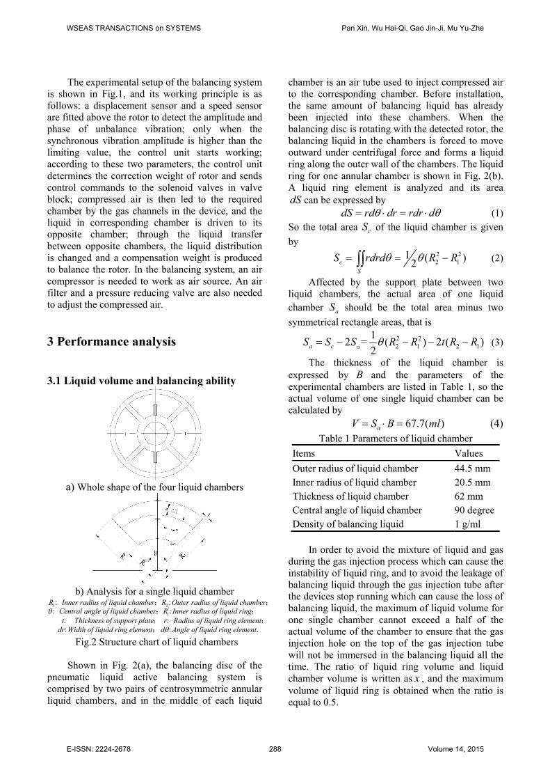
developed, shown in Fig.5. The parameters used in the simulation program were set in accordance with the active balancing experimental device.
The initial vibration amplitude was set to 10 μm, and the vibration phases of the four cases were 90 degree, 180 degree, 270 degree and 360 degree, respectively. For the trial algorithm, the trial sequence of the four liquid chambers was set to A, C, B and D, and the simulation result is shown in Fig.6. For the four cases with different vibration phase, the trial algorithm could effectively reduce the vibration amplitude to below 0.05 μm in about 40 seconds, but the misadjustment phenomenon during the balancing process was unavoidable.
Fig.5 Simulation interface under Labview platform
Fig.6 Simulation results of trial algorithm
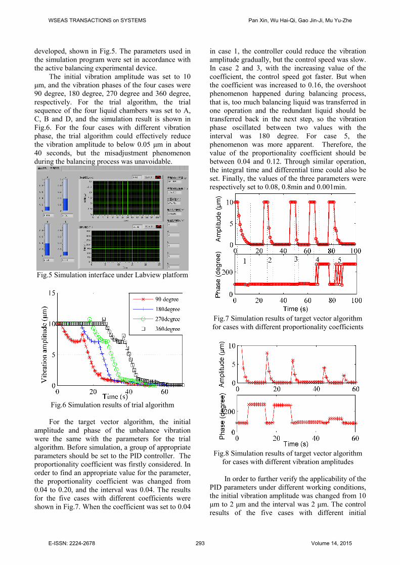
For the target vector algorithm, the initial
amplitude and phase of the unbalance vibration were the same with the parameters for the trial algorithm. Before simulation, a group of appropriate parameters should be set to the PID controller. The proportionality coefficient was firstly considered. In order to find an appropriate value for the parameter, the proportionality coefficient was changed from 0.04 to 0.20, and the interval was 0.04. The results for the five cases with different coefficients were shown in Fig.7. When the coefficient was set to 0.04
in case 1, the controller could reduce the vibration amplitude gradually, but the control speed was slow. In case 2 and 3, with the increasing value of the coefficient, the control speed got faster. But when the coefficient was increased to 0.16, the overshoot phenomenon happened during balancing process, that is, too much balancing liquid was transferred in one operation and the redundant liquid should be transferred back in the next step, so the vibration phase oscillated between two values with the interval was 180 degree. For case 5, the phenomenon was more apparent. Therefore, the value of the proportionality coefficient should be between 0.04 and 0.12. Through similar operation, the integral time and differential time could also be set. Finally, the values of the three parameters were respectively set to 0.08, 0.8min and 0.001min.
Fig.7 Simulation results of target vector algorithm for cases with different proportionality coefficients
Fig.8 Simulation results of target vector algorithm
for cases with different vibration amplitudes
In order to further verify the applicability of the PID parameters under different working conditions, the initial vibration amplitude was changed from 10 μm to 2 μm and the interval was 2 μm. The control results of the five cases with different initial
WSEAS TRANSACTIONS on SYSTEMS Pan Xin, Wu Hai-Qi, Gao Jin-Ji, Mu Yu-Zhe
E-ISSN: 2224-2678 293 Volume 14, 2015

vibration amplitudes were shown in Fig. 8. The target control algorithm with the group of PID parameters could reduce the unbalance vibration with different amplitude to the limit value in 5 seconds and there was no misadjustment phenomenon during active balancing operation.
7 Conclusion In this paper, two performance parameters of the pneumatic liquid online active balancing device were analyzed. For the maximum of the balancing ability, it can be easily increased without changing the size of balancing disc through the change of balancing liquid; for the flow velocity of balancing liquid in the connecting tube, it was related with the liquid volume of the chambers and the total departures of the flow velocity was related with the gas pressure.
During the active balancing process, the control algorithm has great influence on the balancing speed and balancing quality of the active balancing system, so the trial algorithm and target vector algorithm were respectively proposed. To compare the control performance of the two algorithms, a simulation model was firstly built using the Labview software and the parameters in the model were set in accordance with the active balancing experimental device. The two algorithms were applied to the simulation model with different vibration cases, and the results were shown as follows:
1) Although the flow velocity of the balancing liquid during liquid transfer process was a variable value, both of the two control algorithms with appropriate control parameters can effectively reduce the unbalance vibration to the limit value and obtain a high balancing precision.
2) Comparing with the trial algorithm, the target vector algorithm had a faster balancing speed and a shorter balancing time, and there was no misadjustment phenomenon during active balancing operation.
Above all, the simulation results verified the effectiveness of such two algorithms on the balancing device and provided several reference values for the control parameters in the practical applications.
Acknowledgements This study was supported by the Major State
Basic Research Development Program of China (973 Program No. 2012CB026000) and Natural
Science Foundation of China in Key Projects ( No. 51135001). The authors would like to thank for supporting this work. References: [1] M.S. Darlow. Balancing of high-speed
machinery: Theory, methods and experimental results. Mechanical Systems and Signal Processing, Vol. 1, No.1, 1987, pp.105-134.
[2] X.F. Li, L.X. Zheng, and Z.X. Liu. Balancing of flexible rotors without trial weights based on finite element modal analysis. Journal of Vibration and Control, Vol. 19, No.3, 2012, pp. 461-470.
[3] Q.L. Zhao, H.Q. Wang, and J.F. Yao. A novel method of dynamic balance weighting for single-disk rotor system. Wseas transactions on systems, Vol. 11, No.1, 2012, pp.12-21.
[4] D.J. Rodrigues, A.R. Champneys, M.I. Friswell, et al., Experimental investigation of a single-plane automatic balancing mechanism for a rigid rotor, Journal of Sound and Vibration, Vol. 330, No.3, 2011, pp.385-403.
[5] H.W. Chen, Q.J. Zhang and S.Y. Fan, Study on steady-state response of a vertical axis automatic washing machine with a hydraulic balancer using a new approach and a method for getting a smaller deflection angle, Journal of Sound and Vibration, Vol. 330, No.9, 2011, pp. 2017–2030.
[6] V.J. Vande, Continuous automatic balancing of rotating systems, Journal of Mechanical Engineering Science, Vol. 6, No.3, 1964, pp. 264-269.
[7] Z. Gosiewski. Automatic balancing of flexible rotors, part I: Theoretical background. Journal of Sound and Vibration, Vol. 100, No.4, 1985, pp. 551-567.
[8] Z. Gosiewski. Automatic balancing of flexible rotors, PartII: Synthesis of system. Journal of Sound and Vibration, Vol. 114, No.1, 1987, pp. 103-119.
[9] S.W. Dyer and J. Ni, Adaptive influence coefficient control of single-plane active balancing systems for rotating machinery, Journal of Manufacturing Science and Engineering, Vol. 123, No.5, 2001, pp.291-298.
[10] L.F. Chen, X. Cao, J.J. Gao. A study on electromagnetic driven bi-disc compensator for rotor auto-balancing and its movement control. Wseas transactions on systems and control, Vol. 5, No. 5, 2010, pp.333-342.
[11] H.W. Fan, M.Q. Jing, R.C. Ren, et al. New electromagnetic ring balancer for active
WSEAS TRANSACTIONS on SYSTEMS Pan Xin, Wu Hai-Qi, Gao Jin-Ji, Mu Yu-Zhe
E-ISSN: 2224-2678 294 Volume 14, 2015

imbalance compensation of rotating machinery. Journal of Sound and Vibration, Vol. 333, No. 17, 2014, pp. 3837-3858.
[12] D. Hofmann, Apparatus for compensating for unbalance of a rotary body, U.S. Patent, US 4050195, 1977.
[13] S.Z. He. Study of liquid release auto-balancing head. Journal of Zhejiang University (Engineering Science), Vol. 35, No. 4, 2001, pp. 418-422.
[14] W. Shen, L.D. He, J.J. Gao, et al. Dealing with vibration problems of a fume turbine’s rotor by using an electromagnetic active balancing device. Journal of Power Engineering, Vol. 26, No. 3, 2006, pp.337-341.
[15] Y. Zhang, X.S. Mei. Study of online balancing control technique for high- speed spindles. Engineering Sciences, Vol. 15, No. 1, 2013, pp. 87-92.
[16] Y.O. Zhang, W.S. Zhao, T.S. Lu, et al. The attitude control of the four-rotor unmanned helicopter based on feedback linearization control. WSEAS Transactions on Systems, Vol. 12, No. 4, 2013, pp.229-239.
[17] S. Staines A., F. Neri. A matrix transition oriented net for modeling distributed complex computer and communication systems. WSEAS Transactions on Systems, Vol. 13, Art.2, 2014, pp.12-22.
[18] M. Camilleri, F. Neri, M. Papoutsidakis. An algorithmic approach to parameter selection in machine learning using meta-optimization techniques. WSEAS Transactions on Systems, Vol.13, Art.18, 2014, pp. 203-212.
[19] M. Papoutsidakis, D. Piromalis, F. Neri, et al. Intelligent algorithms based on data processing for modular robotic vehicles control. WSEAS Transactions on Systems, Vol.13, Art.22, 2014, pp. 242-251.
[20] Y.G. Liu, Y. Li, S.B. Xia, et al. Optimizing Control of Automatic Balancing of Flexible Rotor. Journal of Vibration Engineering, Vol. 12, No. 4, 1999, pp.559-564.
[21] L.Q. Huang, W.M. Wang, Y.R. Su, et al. Optimal control method and test for rigid rotor auto-balancing, Journal of Vibration and Shock, Vol. 30, No. 5, 2011, pp.101-105.
[22] Y.R. Su, L.D. He, W. Feng. A study of the active balancing technology for the far end optimization of a cantilever rotor. Journal of Engineering for Thermal Energy and Power, Vol. 23, No. 4, 2008, pp. 369- 372.
[23] Y.R. Su, L.D. He, Z.W. Wang, et al. Study on dual-plane active hydraulic balancing technology for single-disk rigid rotor system.
Proceedings of the CSEE, Vol. 29, No. 35, 2009, pp. 119-124.
[24] J.S. Kim, S.H. Lee. The stability of active balancing control using influence coefficients for a variable rotor system. The International Journal of Advanced Manufacturing Technology, Vol. 22, No. 7-8, 2003, pp.562-567.
[25] J.D. Moon, B.S. Kim, and S.H. Lee, Development of the active balancing device for high-speed spindle system using influence coefficients, International Journal of Machine Tools & Manufacture , Vol. 46, No. 9, 2006, pp.978-987.
[26] Y. Li, W. M. Wang, L.Q. Huang, et al. A rotor auto-balance device with continuously injecting and draining liquid based on peristaltic pumps. Journal of Vibration and Shock, Vol. 30, No. 4, 2011, pp.38-41.
[27] Y. Zhang, X.S. Mei, Z.B. Hu, et al. Design and performance analysis of hydrojet-typed balancing device for high-speed machine tool spindle. Journal of Xi’an Jiaotong University, Vol. 47, No. 3, 2013, pp.y1-y6.
[28] X. Pan, H.Q. Wu, J.J. Gao, et al. Study on Online Active Balancing System of Rotating Machinery and Target Control Method. Wseas transactions on systems, Vol. 13, Art. 29, 2014, pp.302-311.
[29] X. Pan, H.Q. Wu, J.J. Gao. Structrual design and performance analysis of a liquid-transfer active balancing device with pneumatic means for grinding machines. Journal of vibration and shock, Vol.33, No.23, 2014, pp.15-18.
[30] X. Pan, H.Q. Wu, J.J. Gao, et al. New liquid transfer active balancing system using compressed air for grinding machine. Journal of Vibration and Acoustics-Transactions of the ASME, Accepted Manuscript, 2014. DOI: 10.1115/ 1.4028507.
[31] L.Y. Chang, H.C. Chen. Tuning of fractional PID controllers using adaptive genetic algorithm for active magnetic bearing system. WSEAS Transactions on Systems, Vol.8, No. 1, 2009, pp. 158-167.
[32] A. M. Kassem. Fuzzy-logic based self-tuning PI controller for high-performance vector controlled induction motor fed by PV-Generator. WSEAS Transactions on Systems, Vol.12, No. 1, 2013, pp. 22-31.
WSEAS TRANSACTIONS on SYSTEMS Pan Xin, Wu Hai-Qi, Gao Jin-Ji, Mu Yu-Zhe
E-ISSN: 2224-2678 295 Volume 14, 2015