Embed Size (px)
Citation preview

Perception and Motion Planning for Pick-and-Place of Dynamic Objects
Anthony Cowley1, Benjamin Cohen1, William Marshall2, Camillo J. Taylor 1 and Maxim Likhachev3
Abstract— Mobile manipulators have brought a new levelof flexibility to traditional automation tasks such as tabletopmanipulation, but are not yet capable of the same speed andreliability as industrial automation. We present approaches to3D perception and manipulator motion planning that enable ageneral purpose robotic platform to recognize and manipulatea variety of objects at a rate of one pick-and-place operationevery 6.7 s, and work with a conveyor belt carrying objects ata speed of 33 cm/s.
I. INTRODUCTION
Robotics researchers regularly endow robot platforms withnew capabilities that increase the breadth of potential appli-cations and push the boundaries of autonomy. In contrast,industrial automation is driven by a pragmatism dictated bythe need to optimize throughput and reliability. The hope ofboth is that, as multi-purpose robotic platforms become morecapable, they will be able to take over an increasing fractionof the tasks currently handled by application specific, fixedinstallation automation, thereby granting all applicationsgreater levels of modularity and adaptability.
We are now seeing an acceleration of the rate at whichresearch robotics feeds into engineering practice. Thiscrossover is arguably being led today by Rethink Robotics’sBaxter platform: a movable manipulation platform with manyof the characteristics of general purpose research platforms,but sold to industry customers. On the research side, generalpurpose robotics has taken a large step forward over the pastfew years, driven in no small part by the development ofWillow Garage’s ROS software ecosystem, Willow Garage’sPR2 mobile manipulation platform, and Microsoft’s Kinectsensor that has made RGB-D perception ubiquitous in robotperception.
We apply these technologies to the problem of tabletopmanipulation at performance levels relevant to industrial use.Performing this task involves 3D object recognition, poseestimation, and the planning of collision-free manipulatortrajectories to first grasp an object, then move it to itsdestination. We present a high performance, high precisionperception and planning combination that enables the PR2to perform pick-and-place operations on dynamic objects byworking with a conveyor belt that drives objects past therobot at a speed of 33 cm/s.
1GRASP Laboratory, University of Pennsylvania, USA{acowley,bcohen,cjtaylor}@seas.upenn.edu
2Lehigh University, USA [email protected] Institute, Carnegie Mellon University, USA
II. RELATED WORK
Factory automation typically relies on careful environmentcontrol and predictable inputs. Industrial perception hashistorically relied on 2D visual sensing where vision sensingis required [1]. This state of affairs is changing as generalpurpose robots lead the shift to less structured environments,a greater variety of behaviors, and full 3D perception andplanning.
Recent approaches to perception for manipulation hasmoved beyond standard 2D image processing by applyinga variety of new sensing modalities to the problem. A multi-flash camera sensor has been used to observe depth edgesof parts piled in a bin [2]. This work focused on finemanipulation in a highly cluttered environment, and was ableto achieve a 94% success rate with just under one secondspent on object pose estimation. Object recognition and poseestimation in complex, noisy scenes is also demonstrated in[3] by relying on an RGB-D sensor.
An example of a responsive general purpose robotic plat-form interacting with moving objects may be found in [4], inwhich a mobile humanoid robot is given the ability to catchballs tossed toward it. This application requires great careand attention be given to processing time, as being late isnot an option. In this case, the software performs real-timecircle detection at 35 ms per image.
The aforementioned PR2 has been used extensively intabletop manipulation research [5]. This work focused onreliability and modularity, and has been demonstrated toenable the PR2 to pick up a variety of objects, includingthose previously unknown to the software.
Raw performance of perception for manipulator planningwas a primary consideration in [6], in which a signedtruncated distance field computed from Kinect data on ahigh-end GPU is used to drive manipulator planning. Theresult is the ability of a manipulation system to execute aplanned, collision free path three seconds after first exposureto the scene.
III. PERCEPTION
The perception system employed here is made up of astaged processing pipeline based on RGB-D sensor data,and the PR2’s own pose estimation, Figure 1. The systemis given information about objects of interest at startup, thentakes its input from ROS, and publishes localized, identifiedobjects as they are detected. The overall procedure is thattable geometry is extracted to perform an initial interpretationof the scene that disregards a large fraction of sensor data.Detected points that lie above the work surface are clustered,and those clusters are recognized and localized to provide

Fig. 1. The perception system is driven by registered depth and colorimages paired with an estimate of the RGB-D sensor’s pose in the robot’scoordinate frame. The dimensionality of the data processed by each stageis indicated in the figure, illustrating places where dimensionality reductionis used to improve efficiency.
a pose estimation of identifiable objects. The individualcomponents of the perception pipeline are described in detailbelow.
A. Conventions
The robot coordinate frame is used to identify features ofthe system and the environment in the following discussion.The convention followed is that common to ROS: a right-handed coordinate system with the X axis extending forwardfrom the robot, the Y axis extending to the robot’s left,and the Z axis extending up from the base. Objects maybe positioned anywhere on the table surface, and are free torotate about their vertical axes.
B. Work Surface Extraction
During execution, the table height, direction, and extentsare periodically re-estimated from direct observation. Thisprocess is run every ten seconds to allow for robot movementduring operation without requiring a reset of the system. Inthis stage, we search for a connected component of the depthimage that is dominated by points within a narrow rangeof heights above ground level using a recursive histogramanalysis.
The inliers of a successful analysis – consisting of asignificant fraction of points within 2 cm of each other whenprojected onto the Z axis – are then used to extract thetable orientation and extents which are used in subsequentobject extraction. Assuming asymmetric geometry, the tableorientation is calculated as the eigenvector corresponding tothe largest magnitude eigenvalue of the covariance matrix ofthe inlier points projected onto the XY plane. When a newtable estimate is computed, it is atomically swapped intoa memory cell referenced at the start of each new objectdetection update.
C. Coarse Recognition and Localization
Upon arrival of a pair of registered depth and color images,all points not within a space above the table geometry pre-viously extracted are immediately removed. The remainingpoints are projected onto the line corresponding to the tabledirection, and clustered using a histogram analysis. Theseclusters are then run through multiple coarse classifiers thatuse color statistics and size limits to reject obvious objecttype mismatches. For instance, if a cluster has a verticalextent of only 10 cm, it will not be identified as an objectexpected to be 30 cm tall.
Multiple coarse recognizers corresponding to the knownobject vocabulary may support any given cluster. All clustersrecognized by at least one coarse recognizer have theircentroids computed, and are fed forward in the system. Whenno coarse recognizer fires, this processing stage provides anopportunity for early exit.
D. Refined Recognition and Localization
The objects to be recognized and localized must be mod-eled before the system will identify them as anything otherthan unknown obstacles. A point cloud of an object’s surfaceis first captured, then used to construct a truncated distancefield representing a uniform sampling of a cost functionwhose minimal manifold corresponds to the surface of theobject model. This sampling is computed by performing aEuclidean distance transform (EDT) on a voxel grid popu-lated from the model point cloud. This preprocessing stepis efficiently performed across multiple CPU cores using theapproach described in [7].
Observed point clusters are recognized by finding a2D transformation that minimizes this cost function whensummed over all observed points. This approach is similar to[8], but the nonlinear optimization technique employed hereis Powell’s dogleg method [9]. The optimization procedureiteratively evaluates 2D transformations applied to 3D pointswhose transformed coordinates are used to index into thesampled cost function until a local minimum is found.
The necessary arithmetic and memory access patterns forthis operation lie squarely within the core competencies ofhardware designed for graphics acceleration. By loading thesampled cost function into a 3D texture in OpenGL, the costof each transformed point is obtained by looking up a floatingpoint value in a texture. The graphics processing unit (GPU)is used to perform linear interpolation along each axis ofthis texture lookup to further smooth the search space, andtexture coordinates are clamped to truncate the cost functionout to infinity, thereby mitigating the deleterious effects ofoutliers.
First, the image coordinates of the relevant points aretranslated to a cropped coordinate frame containing only theobserved points. These coordinates are then paired with the3D points reconstructed from the depth data, transformedinto the object’s coordinate frame using the points’ centroidas the origin, and loaded onto the GPU. The 2D projectionof the original data is used to address the output data as it

is, by construction, an injective mapping from 3D points to2D coordinates.
A GLSL vertex shader applies the candidate transforma-tion, while passing through the 2D coordinates for each pointunchanged. The fragment shader looks up the distance valuefrom the cost function texture, and writes the interpolatedvalue it arrives at to that point’s location in the cropped 2Dcoordinate frame. Additionally, the optimization procedurelends itself to a batch interface, wherein several choices ofparameters are evaluated in an overlapping fashion, therebyallowing the GPU to compute cost function evaluationswhile asynchronously transferring the results of previousevaluations back to the CPU.
When the optimization process has finished, the aver-age distance from each point in the observation under theminimal-cost transformation to the object model is consid-ered to determine if we have a successful identification.Multiple optimizations may be performed to resolve the am-biguity of multiple coarse recognizers positively identifyingpoint cluster summaries. An additional gain in efficiencyis found by considering the rotational symmetry of eachobject. The general problem of identifying a 2D translationand 1D rotation is, for example, reduced to just the 2Dtranslation optimization for objects that are fully symmetric.The rotational symmetry of each object is therefore recordedalong with the object model information used by the coarserecognition step.
E. Tracking
The above process is applied to a small number of ob-served point clusters, while the rest are left as unidentified.All clusters are then passed to a tracking component thatmodels the kinematics of both identified and unidentifiedpoint clouds. Observation integration is achieved by main-taining a track state that includes both object position andvelocity in a Kalman filtering framework.
Inspired by the linear arrangement of objects on a longtable when viewed from off-axis, observations are alignedwith existing estimates using the Needleman-Wunsch op-timal matching algorithm [10]. This algorithm provides aprincipled way to match predictions of a linear chain of statesto observations while taking potential object identificationas well as position into account. This mechanism supportsthe presence of multiple objects within a single view bymatching observations to existing tracks, or determining thatan observation necessitates the initialization of a new track.
The motion model used for tracking is one of zeroacceleration. Furthermore, we are interested in the problemof tracking objects undergoing identical motion. We takeadvantage of this commonality by initializing the positioncovariance estimate of a new track by a sensor noise modelas is usual, but carry over both velocity value and covariancefrom previous tracks. This causes the velocity estimate ofsuccessive tracks to adhere very tightly to a robust runningaverage.
Final reporting from the tracker is governed by a con-figuration parameter indicating how many observations of
any given track are needed before reporting is warranted.When a recognized object track is reported, an estimateof its position on the table plane is extracted from theKalman filter, and a bounded history of orientation estimatesprovided by the localization optimization is passed througha RANSAC [11] procedure to compute a robust mean. Thespecial consideration given to object yaw is due to theexpectation that yaw measurements will be the noisiest axisof observation due to varying geometry occlusion as the viewof an object changes over time. Consider, for example, around watering can with a long spout. The yaw estimate forsuch an object will likely be much better when computedfrom views in which the spout is visible than those where itcan not be seen.
IV. MANIPULATION
When an object is detected, the pick-and-place manipula-tion pipeline gets called to pick up the approaching objectand move it to a desired location. The manipulation pipelineis comprised of three main components, namely grasping,motion planning and execution. Before the pipeline is called,an arm is chosen to pick up the object. Currently we aresimply alternating between the arms. If no feasible grasps forthe first arm are computed, we have found that quite oftenthe other arm is capable of performing the pick-and-placeaction after receiving the next observation.
Note, that the same system is used for manipulating bothstatic and dynamic objects. In the case of the static object, theentire pipeline just executes immediately, instead of waitingfor the object to enter the robot’s workspace.
A. Grasping
Reliable grasping of a static object by a robot’s end-effector can be a difficult task given the uncertainty in eachpart of the system, from the object pose estimation to therobot’s mechanical calibration. Additional problems arisewhen the object is moving at a fast speed. To simplify graspplanning, we exploit the fact that we have a well-defined setof objects to be manipulated. This allows us to restrict theset of grasps for each type of object to ones that we havepreviously tested and saved in a database. Once an object isdetected, the grasps are retrieved and checked for feasibility.We will now explain each component of the grasp selectionprocess.
Types of Grasps. The process of picking up an objectrequires the end-effector to move between three different 6-DOF poses:• pregrasp - An end-effector pose that is offset from
the object (see Figure 2, left). The motion planner isused to plan a collision free trajectory from the arm’swaiting configuration to a valid configuration with theend-effector at the pregrasp pose.
• grasp - The pose of the end-effector in which its fingersare in position to reliably enclose part of the object (seeFigure 2, middle).
• postgrasp - The end-effector pose after it moved awayfrom the surface with the object grasped. The motion
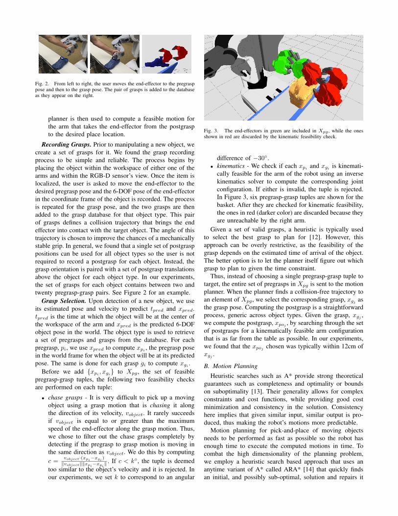
Fig. 2. From left to right, the user moves the end-effector to the pregrasppose and then to the grasp pose. The pair of grasps is added to the databaseas they appear on the right.
planner is then used to compute a feasible motion forthe arm that takes the end-effector from the postgraspto the desired place location.
Recording Grasps. Prior to manipulating a new object, wecreate a set of grasps for it. We found the grasp recordingprocess to be simple and reliable. The process begins byplacing the object within the workspace of either one of thearms and within the RGB-D sensor’s view. Once the item islocalized, the user is asked to move the end-effector to thedesired pregrasp pose and the 6-DOF pose of the end-effectorin the coordinate frame of the object is recorded. The processis repeated for the grasp pose, and the two grasps are thenadded to the grasp database for that object type. This pairof grasps defines a collision trajectory that brings the endeffector into contact with the target object. The angle of thistrajectory is chosen to improve the chances of a mechanicallystable grip. In general, we found that a single set of postgrasppositions can be used for all object types so the user is notrequired to record a postgrasp for each object. Instead, thegrasp orientation is paired with a set of postgrasp translationsabove the object for each object type. In our experiments,the set of grasps for each object contains between two andtwenty pregrasp-grasp pairs. See Figure 2 for an example.
Grasp Selection. Upon detection of a new object, we useits estimated pose and velocity to predict tpred and xpred.tpred is the time at which the object will be at the center ofthe workspace of the arm and xpred is the predicted 6-DOFobject pose in the world. The object type is used to retrievea set of pregrasps and grasps from the database. For eachpregrasp, pi, we use xpred to compute xpi
, the pregrasp posein the world frame for when the object will be at its predictedpose. The same is done for each grasp gi to compute xgi .
Before we add {xpi , xgi} to Xpg , the set of feasiblepregrasp-grasp tuples, the following two feasibility checksare performed on each tuple:
• chase grasps - It is very difficult to pick up a movingobject using a grasp motion that is chasing it alongthe direction of its velocity, vobject. It rarely succeedsif vobject is equal to or greater than the maximumspeed of the end-effector along the grasp motion. Thus,we chose to filter out the chase grasps completely bydetecting if the pregrasp to grasp motion is moving inthe same direction as vobject. We do this by computingc =
vobject·(xpi−xgi
)
‖vobject‖‖xpi−xgi
‖ . If c < k◦, the tuple is deemedtoo similar to the object’s velocity and it is rejected. Inour experiments, we set k to correspond to an angular
Fig. 3. The end-effectors in green are included in Xpg , while the onesshown in red are discarded by the kinematic feasibility check.
difference of −30◦.• kinematics - We check if each xpi
and xgi is kinemati-cally feasible for the arm of the robot using an inversekinematics solver to compute the corresponding jointconfiguration. If either is invalid, the tuple is rejected.In Figure 3, six pregrasp-grasp tuples are shown for thebasket. After they are checked for kinematic feasibility,the ones in red (darker color) are discarded because theyare unreachable by the right arm.
Given a set of valid grasps, a heuristic is typically usedto select the best grasp to plan for [12]. However, thisapproach can be overly restrictive, as the feasibility of thegrasp depends on the estimated time of arrival of the object.The better option is to let the planner itself figure out whichgrasp to plan to given the time constraint.
Thus, instead of choosing a single pregrasp-grasp tuple totarget, the entire set of pregrasps in Xpg is sent to the motionplanner. When the planner finds a collision-free trajectory toan element of Xpg , we select the corresponding grasp, xgj asthe grasp pose. Computing the postgrasp is a straightforwardprocess, generic across object types. Given the grasp, xgj ,we compute the postgrasp, xpoj , by searching through the setof postgrasps for a kinematically feasible arm configurationthat is as far from the table as possible. In our experiments,we found that the xpoj chosen was typically within 12cm ofxgj .
B. Motion Planning
Heuristic searches such as A* provide strong theoreticalguarantees such as completeness and optimality or boundson suboptimality [13]. Their generality allows for complexconstraints and cost functions, while providing good costminimization and consistency in the solution. Consistencyhere implies that given similar input, similar output is pro-duced, thus making the robot’s motions more predictable.
Motion planning for pick-and-place of moving objectsneeds to be performed as fast as possible so the robot hasenough time to execute the computed motions in time. Tocombat the high dimensionality of the planning problem,we employ a heuristic search based approach that uses ananytime variant of A* called ARA* [14] that quickly findsan initial, and possibly sub-optimal, solution and repairs it
while deliberation time allows. The approach also relies ona compact graph representation and informative heuristics toprovide real time performance. Details on this approach andapplications to single and dual-arm motion planning can befound in [15], [16].
We configured the planner to search in a 7 dimensionaltask space, {x, y, z, roll, pitch, yaw, θ}, that represents the6-DOF pose of the end-effector in the world frame, coupledwith θ, the position of the redundant degree of freedom in therobot’s arm. This representation can be used when planningfor a robot with one or more 7-DOF manipulators, such as thePR2 robot. In our experiments, we execute two independentinstances of the planner, one for each arm. The cost functionwe use is aimed to minimize the 6-DOF path length of theend-effector.
During the pick action, the planner is called to plan apath from the waiting configuration of the arm to one of thepregrasps in Xpg . Before planning begins, the geometry ofthe fixed objects in the robot’s workspace are added to thecollision representation. In our experiments, this included theconveyor belt and bins that surrounded the robot. After therobot grasps the object, the collision geometry of the objectis attached to the robot’s collision model. During the placeaction, a plan is requested from the postgrasp to any one ofthe drop poses above the bins. Note that there is nothingconstraining the user from having the robot gently placethe item on a surface instead. Now that a potentially fragileobject (or an object filled with something) is grasped in therobot’s end-effector, we impose an upright path constrainton the planner when computing a path for the place action.The constraint requires the planner to maintain the initial{roll, pitch, yaw} of the end-effector throughout the pathwith a small tolerance in each dimension.
After a path is computed, we pass it through a simpledeterministic shortcutting routine that can deal effectivelywith discretization artifacts. We found that only a singlepass through the points was necessary. In our experiments,the entire shortcutting step lasted between 5-10ms, includingchecking the interpolated motions for collisions every 2◦.
The ability to accurately predict the time it takes toexecute a trajectory is essential to picking up a quicklymoving object. Being that our motion planner plans solelyfor the kinematics of the arm, we then perform a finalpost-processing step, in which the shortest timing intervalsbetween points are computed that enforce the robot’s dy-namic constraints [17]. The waypoint locations themselvesare not moved, instead feasible velocities and accelerationsare assigned. We found in our experiments that on average,for a trajectory from an arm’s initial configuration to apregrasp pose, the predicted execution timing and the actualtrajectory execution timing differ by approximately 80 ms.The pregrasp-to-grasp trajectory is much shorter, whichprovides for a much smaller temporal prediction error, thusmaking the pregrasp pose a useful waypoint at which to makefinal timing adjustments to achieve a precise collision.
C. Execution
Given that the object is moving at a reasonable pace,the pick action is substantially more difficult to executethan the place because very precise timing is needed tosuccesfully pick up the object with a firm grasp. For example,in our experiments the objects moved at approximately33 cm/s across the robot’s workspace. At that velocity, if theexecution of our grasp motion is 100 ms too late, the objectwill have passed xpred by more than 3 cm, and, dependingon the type of the object, it is very likely that the end-effectorwill swipe and miss.
Pick Action. At this stage in the pipeline, it is confirmedthat the entire pick action is kinematically feasible. In thecase of the pick action, the following two trajectories havebeen generated:
• trajp - The pregrasp trajectory begins at the waitingconfiguration of the arm and ends at xpj
. It is acollision free path generated by the motion planner, thenshortcutted and filtered. trajp has a predicted trajectoryexecution duration of dppred
seconds.• trajg - The grasp trajectory begins with the wrist atxpj
, then moves to xgj and ends at xpoj . The path isan open loop motion in which the end-effector moves avery short total distance. trajg is filtered to assure therobot can execute it. Note that we define dgpred as thepredicted trajectory execution duration of the trajectoryfrom the start until xgj . We disregard the execution timefrom xgj to xpoj because the first half of the motion isthe only time sensitive component, given that the end-effector has to be at xgi to pick up the object at xpredat time tpred.
The next step is to determine whether there is enoughtime for the robot to execute both trajectories in time topick up the object at tpred. The pickup is determined to befeasible if tpred > (tnow + dppred
+ dgpred). If the pickupis feasible, then trajp is executed immediatly. After it iscompleted, trajg will begin execution at tgexecute = tpred−dgpred . The end-effector is commanded to start closing as itis approaching the grasp pose. In our experiments, we foundthat depending on how early the object was detected andwhich arm is being used, the robot would sleep for between0.0 and 1.5 seconds between executing the trajectories toensure a well-timed grasp.
Place Action. After the object is grasped and raised to thepostgrasp, there is not much work left to do. The computedpath with the upright orientation constraint on the end-effector is executed immediatly. After the end-effector opens,allowing the object to drop into the desired bin, the armreturns to the waiting configuration. The purpose of thewaiting configuration is two fold. First, it is intended tokeep the arm that is closer to the feed edge of the belt outof the view of the RGB-D sensor, regardless of where thebins are located. Second, it is desirable to keep the arm ina configuration that is close to the table to aid in quickerreaction times by having to execute shorter trajectories.

Fig. 4. The objects used for all experiments.
V. EXPERIMENTS
A. Computing Platforms
All logic related to planning was executed onboard thePR2’s own computers. The perception software was hostedremotely on a desktop computer with an Intel Core i7-2600quad-core CPU at 3.4GHz and an NVIDIA GeForce GT420 GPU with 48 CUDA cores, a low-end graphics cardfrom 2010. The imposition of networking between these twocritical components adds a significant and variable amountof latency to the system, however the PR2 used for theseexperiments did not have a discrete GPU, and so could nothost the perception system itself. The perception pipeline waswritten in the Haskell functional programming language, andcompiled with the GHC1 7.6.1 compiler.
B. Object Selection
The objects chosen, Figure 4, range in height from 15 cmto 45 cm, and breadth from 8 cm to 25 cm. These objectsalso display a variety of rotational symmetries, which affectstheir localization and how the objects may be grasped. Thecandlesticks and tall green bottle have an infinite order ofrotational symmetry, denoted C∞, which translates to afreedom to grasp such an object from any angle, and freesthe localization optimization from needing to consider objectorientation. The shoe is not rotationally symmetric, denotedC1, and must be grasped from its open end. The spritzerbottle is also C1, but may be grasped from either side tohook the PR2’s fingers underneath the overhanging geometryof the trigger mechanism. The various baskets are all C2, astheir handles may be grasped from either side.
Object models were acquired using RoboEarth software[18], a poster with fiducial markers, and a Kinect sensor. Themodels gathered for the experiments described here consistof 500 thousand to 1 million points.
C. Pick-and-Place
Figure 4 shows the conveyor belt used for testing bothstatic grasps, in which objects are placed on the surface infront of the PR2 with the belt motor turned off, and dynamic
1http://www.haskell.org/ghc
grasps, in which the belt motor is on. In the static graspconfiguration, the robot’s head is oriented so that it is lookingdown at the table, and objects are rapidly placed in front of it.As soon as the robot begins to clear the work surface with anobject in hand, a new object is placed on the surface. Objectsare placed such that at least one arm can plausibly performa grasp, but precise position and orientation are allowed tovary within that constraint.
The experiment conducted in the static grasp configurationinvolved 100 pick-and-place operations in which the robotremoves an object placed onto the work surface in front ofit, and places the object into one of two bins placed oneither side of it. Of the 100 attempted actions, 91 weresuccessful. The most common failure mode involved theobject slipping out of the robot’s gripper due to an insecuregrasp. These 100 actions were timed in blocks of 10, yieldingan average of 6.7 s per pick-and-place action. During the timethese experiments were conducted, the perception systemfailed to identify an object before a two second timeoutperiod elapsed on two occasions. The experiments in whichperception failed are not included in the reported time, aswe did not have a consistent approach to failure recovery.
The dynamic configuration shown in the video associatedwith this paper has the robot looking down the length ofthe conveyor belt, as in Figure 4. Objects are placed onthe far end of the 2.13 m belt, and carried past the robot.In this configuration, the perception system only reports onobjects it has seen a minimum of three times. This limitssystem responsiveness, but is important to eliminate spuriousobservations of the object being hand-placed on the end ofthe belt, and to ensure stability in pose estimation.
System performance was measured over 100 pick-and-place operation attempts with the belt at its top speed, 33 cm/s,87 of which were successful. Six objects were effectivelyignored due to the planner being unable to compute a suitabletrajectory for either arm in the allotted time. Of these six,five were spritzer bottles, suggesting that the grasps chosenfor this object did not leave the planner enough freedom tomaneuver. The seven other failures were fumbled grasps. Asin the static test, sometimes an insecure grasp would leadto an object being dropped. The dynamic test added thenew failure mode of objects bouncing off of the back ofthe open gripper during a catch attempt. This contributionof momentum to the experiment was an excellent test of thesystem’s overall timing: the gripper had to close around theobject as it hooked available geometry in order to absorball of its momentum without excessively destabilizing theobject. The tight timing constraints, paired with the designof the PR2’s arms, meant that the robot’s arm farther fromwhere the objects were coming from was easier to utilize.Of the 94 attempted grasps, 57 were made by the far arm.
VI. ANALYSIS
A. Perception Performance
Preprocessing includes collecting a point cloud for eachobject to be identified. The raw point data is used to populatea 0.5 cm3 resolution voxel grid, then passed through a

0.00
0.05
0.10
0.15
0 25 50 75 100 125Refinement (mm)
dens
ity
Widget Type
candlestick
big basket
shoe
tall bottle
small basket
spritzer
Optimization Impact by Object Type
Fig. 5. A nonlinear optimization that fits observed points to a per-objectcost function refines an initial localization estimate provided by each pointcluster’s centroid.
Euclidean Distance Transform (EDT), taking an average of304 ms for each object.
Once the system is running, parameters describing the con-veyor belt surface are periodically recalculated as describedin Section III-B. This process took an average of 39 msper update, and was run concurrently with the rest of theperception pipeline in a separate thread.
The localization step begins by considering the centroidof each cluster of points found above the table surface. Thisis a reasonably good estimate of the object’s position, butis biased towards the camera due to self-occlusion of theobject geometry. The goal of navigating the PR2’s fingerinto an opening with approximately 1 cm clearance on eitherside (e.g. underneath a spritzer bottle’s trigger) demands alevel of accuracy in object pose estimation which can bedifficult to achieve when using only point cluster centroids.However, the localization refinement step represents a signif-icant fraction of all the time spent in perception, so its utilityis of interest. Recovering object yaw is critical for graspingasymmetric objects, but focusing solely on translational poseestimation reveals further contributions made by refininginitial coarse position estimates.
Figure 5 illustrates the translation corrections made by theoptimizer to an initial localization estimate based on pointcluster centroids with a kernel density estimate of observedrefinements. Note that in this run of experiments, there wereno false identifications and no wild misses by the robot.The two object types needing the greatest correction fromtheir initial centroid estimates were the big basket and theshoe, which are the two objects with the greatest asymmetryin the XY plane. The big basket is also a tall object,
0.00
0.02
0.04
0.06
53 100Time (ms)
dens
ity
Widget Type
unknown
candlestick
big basket
shoe
tall bottle
small basket
spritzer
Perception Performance
Fig. 6. Perception performance broken down by object type. The overallmean is 53 ms.
resulting in views looking down the table that primarilysee the near side of the object. In contrast, most of theperimeter of an item like the small basket could be seen at theavailable view angle. This contrast is borne out by the effectof the optimization on these two objects: the big basket’stranslational position was shifted an average of 3.4 cm fromthe point cluster centroid, while the small basket was shiftedan average of 0.9 cm.
The average processing time for the perception systemover the 5117 object detections during the moving objectexperiment was 53 ms, Figure 6. The “tall bottle” object wasthe slowest to process, at an average of 77 ms per update.Initial filtering, clustering, and coarse recognition comprisethe first perception phase, taking an average of 22.2 ms.The second phase consists of the localization optimizationprocedure, taking an average of 31.1 ms. The final trackingphase did not take a significant amount of time.
The average processing time for the motion planner duringthe moving object experiment was 182 ms, including timespent in ROS service calls. This gives a minimum systemresponse time on the order of 250 ms if only one observationof a scene is needed. For applications such as dynamic objectmanipulation, multiple observations may be needed, whichpushes the delay before action to over 400 ms. The perfor-mance of these experiments is thus completely dominatedby the speed at which the PR2 can move its arms. The PR2requires approximately 4.5 s to perform the motions neededfor these tasks, which puts a lower limit on how quickly theentire system can process pick-and-place tasks.
B. Robustness
Execution time – a limiting factor in system responsive-ness – was consistent throughout the experiments described.
The longest single perception update in the dynamic testcovering 5117 updates took 132 ms. There are many sourcesof variance in these timings as the perception system wasrunning on the GHC Haskell runtime system with its gen-erational garbage collector, which itself was running in adesktop Linux environment (Ubuntu 10.04).
Localization accuracy was measured by considering thePR2’s effective “hand-eye coordination.” We used the PR2’sproprioception to obtain an estimate of the location of oneof the robot’s fingertips with its arm extended over the worksurface and angled down so that the finger just touched thesurface. The location of this tangent was marked, and thearm was removed from the work area. A candidate objectwas then placed at the marked location, and the localizationreturned by the perception system was compared with thePR2’s own estimate of where its finger had been.
These experiments yielded an average discrepancy be-tween proprioception and perception of 5.3 mm. A meterstick was then used to move the object one meter downthe work surface from its starting location. The robot’s headwas turned to face this new location, and the output ofperception was again recorded. This relative motion estimateyielded an average discrepancy between the meter stick andthe perception system of 6.7 mm.
The last metric recorded from the perception systemwas the speed of the belt. This was estimated during theexperiment by tracking objects over time. The perceptionsystem estimated the belt speed at 33.1 cm/s, with a standarddeviation of 0.08 cm/s. We were unable to obtain anothermeasurement of belt speed with less noise.
The reported timings include all segmentation, recogni-tion, and localization. There is additional overhead in theintegrated system due to running the perception calculationsremotely from the PR2 itself. The net result was a ROS objectdetection publisher rate that varied between 10 and 12 Hz,the same rate at which raw depth images were received atthe perception computer.
VII. CONCLUSION
We have demonstrated pick-and-place operations per-formed by a PR2 at a rate of 6.7 s per object at a 91% successrate. Similar operations on a moving work surface yield an87% success rate. Room for improvement remains in theareas of system integration, and end-effector customization.The speed at which the PR2’s arms can move proved tobe a limiting factor in system performance, and the gripperdesign was not particularly suited to absorbing the impactof moving objects. Despite these mechanical limitations, thePR2 proved to be capable of responsive, high throughputobject manipulation.
REFERENCES
[1] J. A. Marvel, R. D. Eastman, G. S. Cheok, K. S. Saidi, T. Hong,E. R. Messina, B. Bollinger, P. Evans, J. Guthrie, E. Hershberger,C. Martinez, K. McNamara, and J. Wells, “Technology readiness levelsfor randomized bin picking,” in Performance Metrics for IntelligentSystems (PerMIS), 2012.
[2] M.-Y. Liu, O. Tuzel, A. Veeraraghavan, Y. Taguchi, T. K. Marks, andR. Chellappa, “Fast object localization and pose estimation in heavyclutter for robotic bin picking,” The International Journal of RoboticsResearch, 2012.
[3] C. Papazov, S. Haddadin, S. Parusel, K. Krieger, and D. Burschka,“Rigid 3d geometry matching for grasping of known objects incluttered scenes,” International Journal of Robotics Research, vol. 31,pp. 538–553, 2012.
[4] O. Birbach, U. Frese, and B. Bauml, “Realtime perception for catchinga flying ball with a mobile humanoid,” in IEEE International Confer-ence on Robotics and Automation (ICRA), 2011, pp. 5955–5962.
[5] S. Chitta, E. G. Jones, M. Ciocarlie, and K. Hsiao, “Perception,planning, and execution for mobile manipulation in unstructuredenvironments,” IEEE Robotics and Automation Magazine, SpecialIssue on Mobile Manipulation, vol. 19, 2012.
[6] R. Wagner, U. Frese, and B. Bauml, “3d modeling, distance andgradient computation for motion planning: A direct gpgpu approach,”in Proceedings of the IEEE International Conference on Robotics andAutomation (ICRA 2013), 2013.
[7] A. Meijster, J. Roerdink, and W. Hesselink, “A general algorithmfor computing distance transforms in linear time,” MathematicalMorphology and its applications to image and signal processing, pp.331–340, 2002.
[8] C. Papazov and D. Burschka, “Stochastic global optimization forrobust point set registration,” Computer Vision and Image Understand-ing, vol. 115, no. 12, pp. 1598–1609, Dec. 2011.
[9] M. J. D. Powell, “An efficient method for finding the minimumof a function of several variables without calculating derivatives,”Computer Journal, vol. 7, no. 2, pp. 155–162, 1964.
[10] S. B. Needleman and C. D. Wunsch, “A general method applicable tothe search for similarities in the amino acid sequence of two proteins,”Journal of molecular biology, vol. 48, no. 3, pp. 443–453, Mar. 1970.
[11] M. A. Fischler and R. C. Bolles, “Random sample consensus: aparadigm for model fitting with applications to image analysis andautomated cartography,” Commun. ACM, vol. 24, no. 6, pp. 381–395,June 1981. [Online]. Available: http://doi.acm.org/10.1145/358669.358692
[12] K. Hsiao, S. Chitta, M. Ciocarlie, and E. Jones, “Contact-reactivegrasping of objects with partial shape information,” in IntelligentRobots and Systems (IROS), 2010 IEEE/RSJ International Conferenceon, Oct., pp. 1228–1235.
[13] J. Pearl, Heuristics: Intelligent Search Strategies for Computer Prob-lem Solving. Addison-Wesley, 1984.
[14] M. Likhachev, G. Gordon, and S. Thrun, “ARA*: Anytime A* withprovable bounds on sub-optimality,” in Advances in Neural Informa-tion Processing Systems (NIPS) 16. Cambridge, MA: MIT Press,2003.
[15] B. J. Cohen, G. Subramanian, S. Chitta, and M. Likhachev, “Planningfor Manipulation with Adaptive Motion Primitives,” in Proceedingsof the IEEE International Conference on Robotics and Automation(ICRA), 2011.
[16] B. Cohen, S. Chitta, and M. Likhachev, “Search-based planningfor dual-arm manipulation with upright orientation constraints,” inProceedings of the IEEE International Conference on Robotics andAutomation (ICRA). St. Paul, Minnesota: IEEE, 2012.
[17] K. Anderson, “Smoother and more efficient trajectory planning,” July2012. [Online]. Available: http://www.willowgarage.com/blog/2012/07/13/smoother-and-more-efficient-trajectory-planning
[18] D. Di Marco, A. Koch, O. Zweigle, K. Haussermann, B. Schiessle,P. Levi, D. Galvez-Lopez, L. Riazuelo, J. Civera, J. M. M. Montiel,M. Tenorth, A. Perzylo, M. Waibel, and R. van de Molengraft,“Creating and using roboearth object models,” in IEEE InternationalConference on Robotics and Automation (ICRA), 2012, pp. 3549–3550.