Embed Size (px)
Citation preview
AIAA SciTech
4-8 January 2016, San Diego, California, USA
54th AIAA Aerospace Sciences Meeting
AIAA 2016-1635
This material is declared a work of the U.S. Government and is not subject to copyright protection in the United States.
Perceived Noise Analysis for Offset Jets Applied to
Commercial Supersonic Aircraft
Dennis L. Huff1, Brenda S. Henderson2, Jeffrey J. Berton3 and Jonathan A. Seidel.4
NASA Glenn Research Center, Cleveland, Ohio, 44135
A systems analysis was performed with experimental jet noise data, engine/aircraft
performance codes and aircraft noise prediction codes to assess takeoff noise levels and
mission range for conceptual supersonic commercial aircraft. A parametric study was done
to identify viable engine cycles that meet NASA’s N+2 goals for noise and performance.
Model scale data from offset jets were used as input to the aircraft noise prediction code to
determine the expected sound levels for the lateral certification point where jet noise
dominates over all other noise sources. The noise predictions were used to determine the
optimal orientation of the offset nozzles to minimize the noise at the lateral microphone
location. An alternative takeoff procedure called “programmed lapse rate” was evaluated
for noise reduction benefits. Results show there are two types of engines that provide
acceptable mission range performance; one is a conventional mixed-flow turbofan and the
other is a three-stream variable-cycle engine. Separate flow offset nozzles reduce the noise
directed toward the thicker side of the outer flow stream, but have less benefit as the core
nozzle pressure ratio is reduced. At the systems level for a three-engine N+2 aircraft with
full throttle takeoff, there is a 1.4 EPNdB margin to Chapter 3 noise regulations predicted
for the lateral certification point (assuming jet noise dominates). With a 10% reduction in
thrust just after clearing the runway, the margin increases to 5.5 EPNdB. Margins to
Chapter 4 and Chapter 14 levels will depend on the cumulative split between the three
certification points, but it appears that low specific thrust engines with a 10% reduction in
thrust (programmed lapse rate) can come close to meeting Chapter 14 noise levels. Further
noise reduction is possible with engine oversizing and derated takeoff, but more detailed
mission studies are needed to investigate the range impacts as well as the practical limits for
safety and takeoff regulations.
Nomenclature
A = area
AAPL = Aero-Acoustics Propulsion Laboratory
AAVP = Advanced Air Vehicles Program
ANOPP = Aircraft Noise Prediction Program
BPR = bypass ratio
CST = Commercial Supersonic Technology
DoD = Department of Defense
DOE = design of experiments
EPNL = effective perceived noise level
EPNdB = effective perceived noise level in decibels
FAR = federal aviation regulation
FPR = fan pressure ratio
GE = General Electric
HFJER = high flow jet exit rig
HSR = High Speed Research program
1 Research Aerospace Engineer, Acoustics Branch, MS 54-3, AIAA Associate Fellow. 2 Research Aerospace Engineer, Acoustics Branch, MS 54-3, AIAA Associate Fellow. 3 Aerospace Engineer, Propulsion Systems Analysis Branch, MS 5-11, AIAA Senior Member. 4 Aerospace Engineer, Propulsion Systems Analysis Branch, MS 5-11, AIAA Senior Member.
American Institute of Aeronautics and Astronautics
2
IVP = inverted velocity profile
M = Mach
MFTF = mixed-flow turbofan
NATR = nozzle acoustic test rig
NPSS = numerical propulsion system simulation
NPR = nozzle pressure ratio
NTR = nozzle temperature ratio
OPR = overall pressure ratio
PLdB = perceived noise level in decibels
PLR = programmed lapse rate
PNL = perceived noise level
PNLT = tone-corrected perceived noise level
SPL = sound pressure level
TOGW = takeoff gross weight
VCE = variable cycle engine
Subscripts
b = bypass
c = core
fj = free jet
t = tertiary
I. Introduction
he Commercial Supersonic Technology (CST) project of the Advanced Air Vehicles Program (AAVP) at
NASA is developing enabling technologies for supersonic aircraft to meet environmental and performance
requirements. One of the technology challenges is to minimize the propulsion noise for low-boom aircraft. The
goal is to develop design tools and innovative concepts for integrated supersonic propulsion systems with
cumulative aircraft noise levels of 10 EPNdB under ICAO Chapter 4 regulations. A summary of NASA’s
supersonic aircraft technology research goals is shown in Table 1.1 The overall approach for supersonic aircraft
development is to start with smaller payloads for the near-term (N+1) and increase the aircraft size over time (N+2
and N+3), while simultaneously meeting environmental and performance goals. There are specific goals for noise,
emissions and performance across the entire aircraft mission for takeoff, cruise and landing.
Table 1. Research goals for supersonic aircraft.1
N+1 supersonic business class aircraft
(2015)
N+2 small supersonic airliner
(2020)
N+3 efficient multi-Mach aircraft
(beyond 2030)
Environmental goals
Sonic boom 65 to 70 PLdB 65 to 70 PLdB 65 to 70 PLdB
low-boom flight
75 to 80 PLdB
overwater flight
Airport noise
(cum below Chapter 4)
Meet with margin 10 EPNdB 10 to 20 EPNdB
Cruise emissions
(cruise NOx g/kg of fuel)
Equivalent to subsonic <10 <5 and particulate and
water vapor mitigation
Performance goals
Cruise speed Mach 1.6 to 1.8 Mach 1.6 to 1.8 Mach 1.3 to 2.0
Range (n mi) 4000 4000 4000 to 5500
Payload (passengers) 6 to 20 35 to 70 100 to 200
Fuel efficiency
(pass-miles per lb of fuel)
1.0 3.0 3.5 to 4.5
T
American Institute of Aeronautics and Astronautics
3
Another major challenge for commercial supersonic aircraft is the continued success of noise reduction for the
subsonic fleet and the subsequent increased stringency of international noise regulations. The recent approval of
Chapter 14 noise regulations by ICAO requires new subsonic aircraft in a comparable N+2 vehicle class to be 7
EPNdB (effective perceived noise level) cum under Chapter 4 levels by 2017.2 In addition, there needs to be
sufficient margin below the regulations to account for uncertainties and growth versions of aircraft. This will likely
require even more aggressive noise reduction goals for supersonic aircraft.
The difficulty of simultaneously meeting the noise, emissions and performance goals makes supersonic engines
good candidates for variable or adaptive cycles. For example, a third flow stream is being considered that
effectively increases the bypass ratio of the engine during takeoff. A benefit of this approach is to reduce takeoff
community noise and still meet engine performance requirements for high-speed cruise. Recent NASA propulsion
system studies for an N+2 commercial supersonic transport have focused primarily on the use of Variable Cycle
Engine (VCE) adaptations to a military-style Mixed-Flow TurboFan (MFTF). This focus originated from early
conceptual studies supporting NASA’s High Speed Research (HSR) Program, which identified a variable tip-fan
engine architecture as an engine cycle with promise to overcome evolving commercial acoustic certification
challenges.3,4 Reinforcing this pursuit of engine architecture are engine-company and U.S. Department of Defense
(DoD) investments in VCE technologies for future military propulsion systems. The NASA VCE studies
parametrically build upon broader investigations in MFTF propulsion trades spanning a range in engine Bypass
Ratio (BPR) and Fan Pressure Ratio (FPR).5,6,7
Supersonic engines, however, must balance the drag associated with higher BPR (low specific thrust) cycles in
achieving both acceptable cruise performance and acceptable take-off noise levels. Inlets and nozzles designed for
optimum supersonic cruise must meet diverse inlet airflow demands and nozzle expansion ratios to attain successful
performance across a large range of flight Mach numbers. In addition, there is a desire for commercial supersonic
vehicles to achieve a high fineness ratio, which impacts the outer mold lines of the inlet, engine nacelle, and nozzle
to reduce the sonic-boom during overland supersonic flight. This dichotomy between the optimum engine for
takeoff noise and the optimum engine for cruise efficiency and sonic boom necessitates a compromise in acceptable
fuel economy and/or weight to achieve commercial acceptability.
This paper investigates the benefits of offset jets for N+2 supersonic vehicles. An engine parametric study was
conducted that identifies acceptable design criteria for meeting performance and noise goals. Model scale
experimental data from recent offset nozzle tests are used to investigate perceived noise reduction of jet noise at full
scale for takeoff conditions. NASA’s ANOPP (Aircraft Noise Prediction Program) code is used to “fly” the engine
through a representative trajectory to assess lateral takeoff noise, which is a certification point where jet noise
dominates over other noise sources. The azimuthal angles of the offset nozzles are varied to determine the best
orientation on the three-engine aircraft for minimizing perceived noise. The impact of an alternative takeoff
procedure called “programmed lapse rate” (PLR) is also investigated.
II. Engine Parametric Study
A parametric study of a MFTF and VCE was conducted to investigate aircraft performance (mission range)
trades with takeoff noise levels. A jet noise component-EPNL was calculated as the acoustic figure of merit using a
maximum power flyover. A reference study vehicle was supplied by the NASA Langley Research Center that is
representative of the Lockheed Martin “1044” aircraft, which has three engines embodying low-boom weight and
aerodynamic characteristics.8 The NASA reference vehicle has a Takeoff Gross Weight (TOGW) of 290,000
pounds, a design range of approximately 4200 nautical miles, a cruise speed of Mach 1.70, and meets commercial
Federal Aviation Regulations (FARs) with practical limits (e.g. engine-out sizing, field-length requirements,
reasonable take-off and landing speeds, etc.).
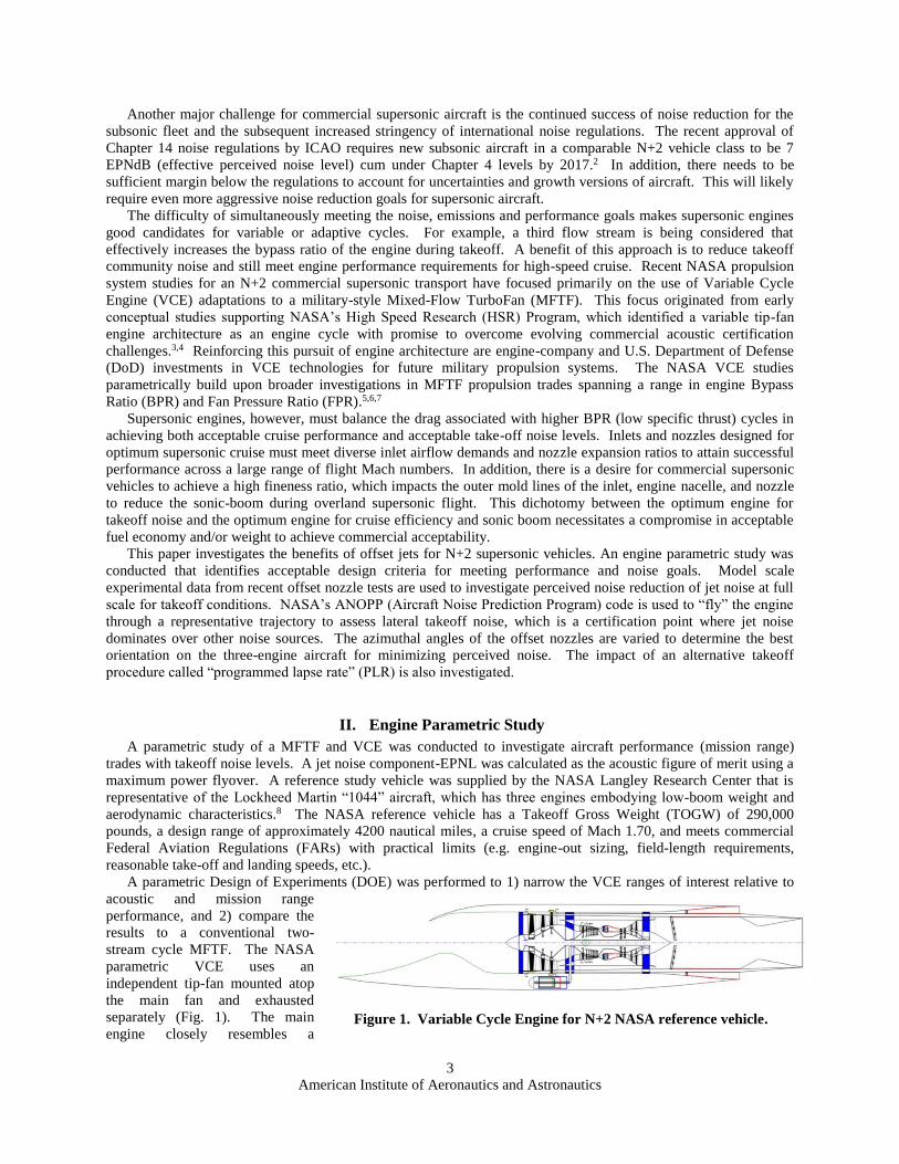
A parametric Design of Experiments (DOE) was performed to 1) narrow the VCE ranges of interest relative to
acoustic and mission range
performance, and 2) compare the
results to a conventional two-
stream cycle MFTF. The NASA
parametric VCE uses an
independent tip-fan mounted atop
the main fan and exhausted
separately (Fig. 1). The main
engine closely resembles a
Figure 1. Variable Cycle Engine for N+2 NASA reference vehicle.
American Institute of Aeronautics and Astronautics
4
military-style two-spool MFTF, with additional VCE features of cooling flow modulation to help balance work
between the spools during part-power operation. The tip-fan flow is modulated throughout the mission envelope of
speed and altitude, optimizing maximum installed net thrust for max-power conditions and minimum specific fuel
consumption for part-power. A simple algorithm was used within the Numerical Propulsion System Simulation
(NPSS) code to conduct an installed propulsion optimization which included inlet performance (pressure recovery
and installed drag) as well as aft-body nozzle installation drag.
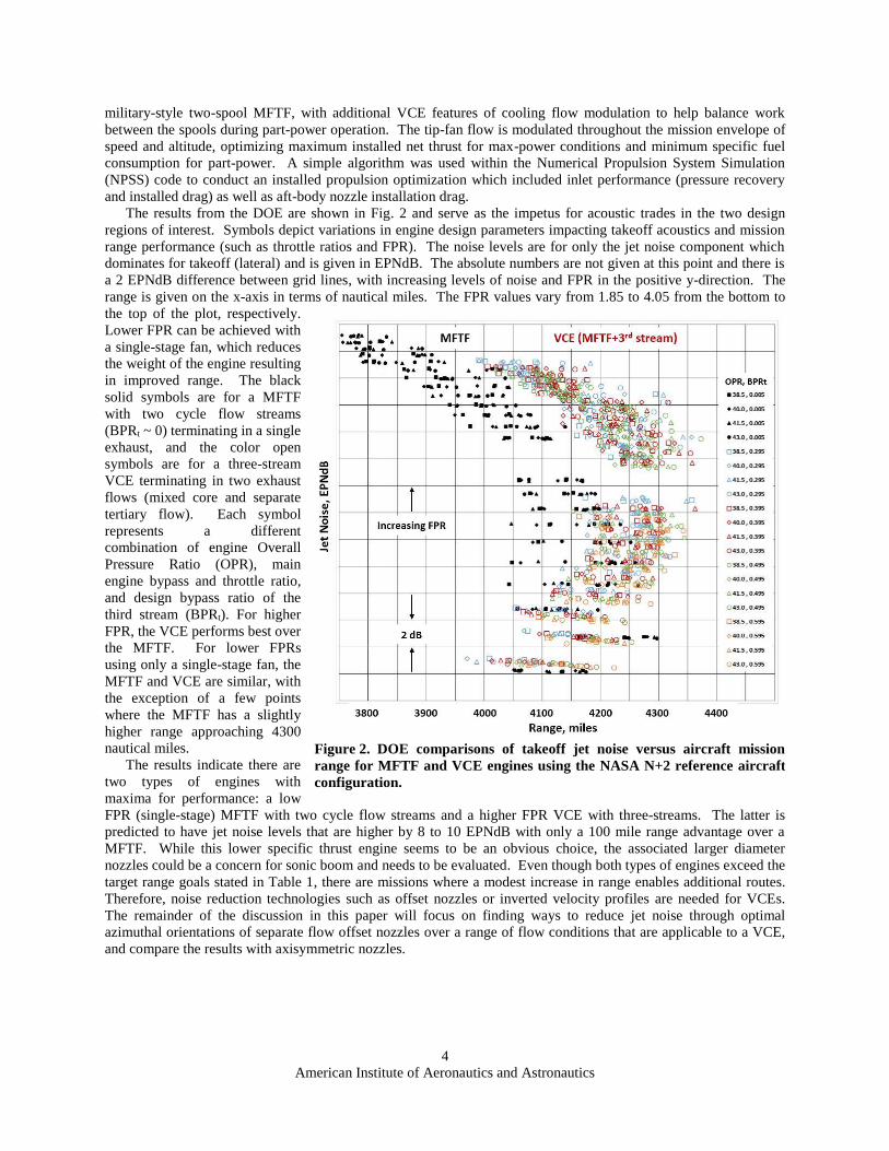
The results from the DOE are shown in Fig. 2 and serve as the impetus for acoustic trades in the two design
regions of interest. Symbols depict variations in engine design parameters impacting takeoff acoustics and mission
range performance (such as throttle ratios and FPR). The noise levels are for only the jet noise component which
dominates for takeoff (lateral) and is given in EPNdB. The absolute numbers are not given at this point and there is
a 2 EPNdB difference between grid lines, with increasing levels of noise and FPR in the positive y-direction. The
range is given on the x-axis in terms of nautical miles. The FPR values vary from 1.85 to 4.05 from the bottom to
the top of the plot, respectively.
Lower FPR can be achieved with
a single-stage fan, which reduces
the weight of the engine resulting
in improved range. The black
solid symbols are for a MFTF
with two cycle flow streams
(BPRt ~ 0) terminating in a single
exhaust, and the color open
symbols are for a three-stream
VCE terminating in two exhaust
flows (mixed core and separate
tertiary flow). Each symbol
represents a different
combination of engine Overall
Pressure Ratio (OPR), main
engine bypass and throttle ratio,
and design bypass ratio of the
third stream (BPRt). For higher
FPR, the VCE performs best over
the MFTF. For lower FPRs
using only a single-stage fan, the
MFTF and VCE are similar, with
the exception of a few points
where the MFTF has a slightly
higher range approaching 4300
nautical miles.
The results indicate there are
two types of engines with
maxima for performance: a low
FPR (single-stage) MFTF with two cycle flow streams and a higher FPR VCE with three-streams. The latter is
predicted to have jet noise levels that are higher by 8 to 10 EPNdB with only a 100 mile range advantage over a
MFTF. While this lower specific thrust engine seems to be an obvious choice, the associated larger diameter
nozzles could be a concern for sonic boom and needs to be evaluated. Even though both types of engines exceed the
target range goals stated in Table 1, there are missions where a modest increase in range enables additional routes.
Therefore, noise reduction technologies such as offset nozzles or inverted velocity profiles are needed for VCEs.
The remainder of the discussion in this paper will focus on finding ways to reduce jet noise through optimal
azimuthal orientations of separate flow offset nozzles over a range of flow conditions that are applicable to a VCE,
and compare the results with axisymmetric nozzles.
Figure 2. DOE comparisons of takeoff jet noise versus aircraft mission
range for MFTF and VCE engines using the NASA N+2 reference aircraft
configuration.
American Institute of Aeronautics and Astronautics
5
III. Experiments
A. Offset Nozzles
Offset nozzles have been investigated as a way to reduce jet noise by introducing an asymmetric noise field in
the azimuthal direction. Papamoschou9 found that offsetting the bypass stream of a supersonic jet decreases the
Mach wave radiation on the thicker side of the jet due to
increased mixing and a reduced potential core length.
Subsequent experiments and analyses have been done to
better understand the noise reduction mechanisms for offset
streams including s-ducts and turning vanes for diverting the
flow. For the current study, the tertiary nozzle was offset
relative to the core and bypass nozzles for a separate flow
exhaust.
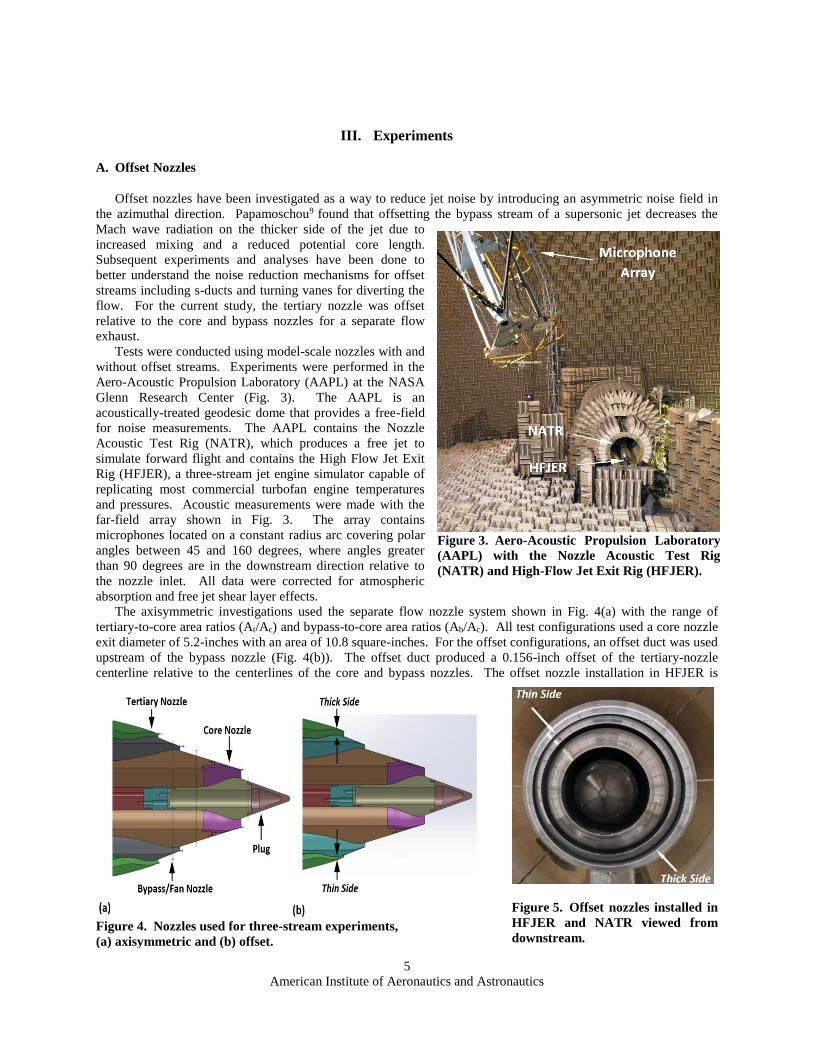
Tests were conducted using model-scale nozzles with and
without offset streams. Experiments were performed in the
Aero-Acoustic Propulsion Laboratory (AAPL) at the NASA
Glenn Research Center (Fig. 3). The AAPL is an
acoustically-treated geodesic dome that provides a free-field
for noise measurements. The AAPL contains the Nozzle
Acoustic Test Rig (NATR), which produces a free jet to
simulate forward flight and contains the High Flow Jet Exit
Rig (HFJER), a three-stream jet engine simulator capable of
replicating most commercial turbofan engine temperatures
and pressures. Acoustic measurements were made with the
far-field array shown in Fig. 3. The array contains
microphones located on a constant radius arc covering polar
angles between 45 and 160 degrees, where angles greater
than 90 degrees are in the downstream direction relative to
the nozzle inlet. All data were corrected for atmospheric
absorption and free jet shear layer effects.
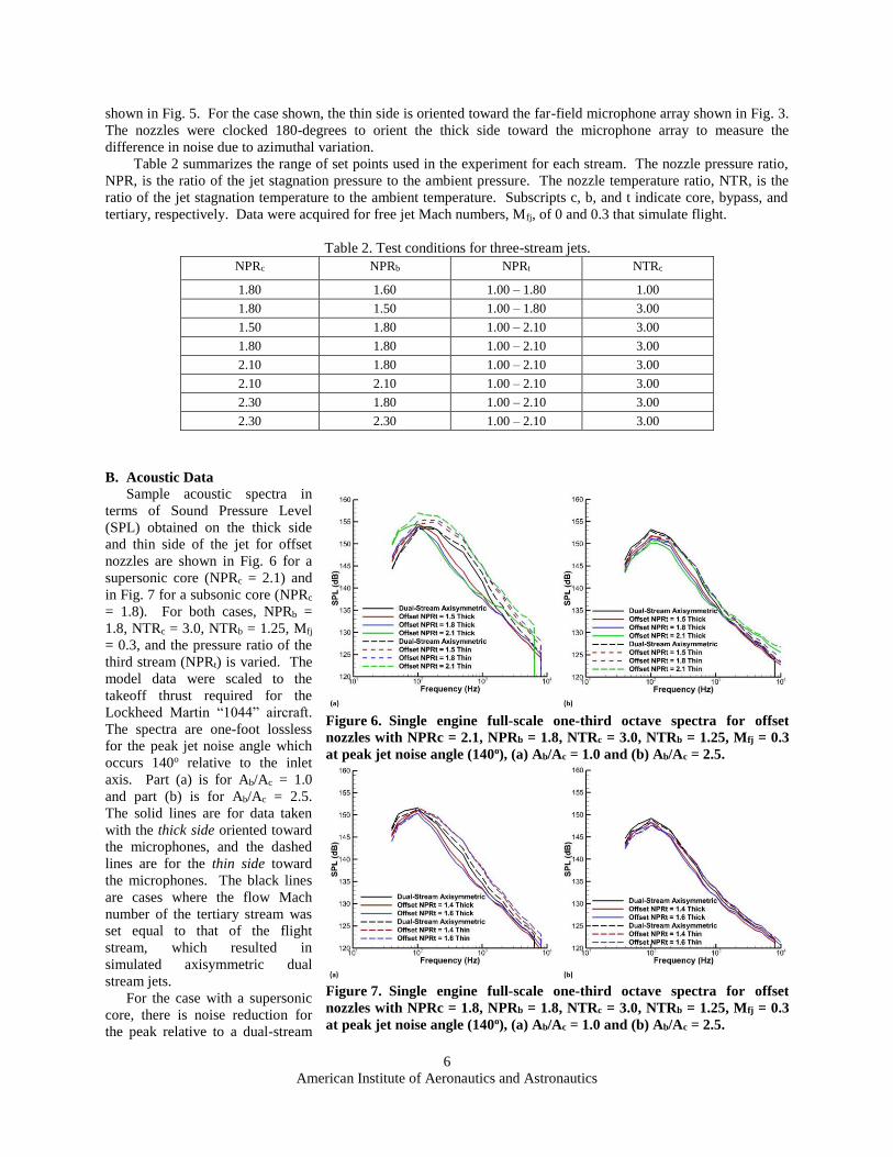
The axisymmetric investigations used the separate flow nozzle system shown in Fig. 4(a) with the range of
tertiary-to-core area ratios (At/Ac) and bypass-to-core area ratios (Ab/Ac). All test configurations used a core nozzle
exit diameter of 5.2-inches with an area of 10.8 square-inches. For the offset configurations, an offset duct was used
upstream of the bypass nozzle (Fig. 4(b)). The offset duct produced a 0.156-inch offset of the tertiary-nozzle
centerline relative to the centerlines of the core and bypass nozzles. The offset nozzle installation in HFJER is
Figure 3. Aero-Acoustic Propulsion Laboratory
(AAPL) with the Nozzle Acoustic Test Rig
(NATR) and High-Flow Jet Exit Rig (HFJER).
Figure 4. Nozzles used for three-stream experiments,
(a) axisymmetric and (b) offset.
Figure 5. Offset nozzles installed in
HFJER and NATR viewed from
downstream.
American Institute of Aeronautics and Astronautics
6
shown in Fig. 5. For the case shown, the thin side is oriented toward the far-field microphone array shown in Fig. 3.
The nozzles were clocked 180-degrees to orient the thick side toward the microphone array to measure the
difference in noise due to azimuthal variation.
Table 2 summarizes the range of set points used in the experiment for each stream. The nozzle pressure ratio,
NPR, is the ratio of the jet stagnation pressure to the ambient pressure. The nozzle temperature ratio, NTR, is the
ratio of the jet stagnation temperature to the ambient temperature. Subscripts c, b, and t indicate core, bypass, and
tertiary, respectively. Data were acquired for free jet Mach numbers, Mfj, of 0 and 0.3 that simulate flight.
Table 2. Test conditions for three-stream jets.
NPRc NPRb NPRt NTRc
1.80 1.60 1.00 – 1.80 1.00
1.80 1.50 1.00 – 1.80 3.00
1.50 1.80 1.00 – 2.10 3.00
1.80 1.80 1.00 – 2.10 3.00
2.10 1.80 1.00 – 2.10 3.00
2.10 2.10 1.00 – 2.10 3.00
2.30 1.80 1.00 – 2.10 3.00
2.30 2.30 1.00 – 2.10 3.00
B. Acoustic Data
Sample acoustic spectra in
terms of Sound Pressure Level
(SPL) obtained on the thick side
and thin side of the jet for offset
nozzles are shown in Fig. 6 for a
supersonic core (NPRc = 2.1) and
in Fig. 7 for a subsonic core (NPRc
= 1.8). For both cases, NPRb =
1.8, NTRc = 3.0, NTRb = 1.25, Mfj
= 0.3, and the pressure ratio of the
third stream (NPRt) is varied. The
model data were scaled to the
takeoff thrust required for the
Lockheed Martin “1044” aircraft.
The spectra are one-foot lossless
for the peak jet noise angle which
occurs 140o relative to the inlet
axis. Part (a) is for Ab/Ac = 1.0
and part (b) is for Ab/Ac = 2.5.
The solid lines are for data taken
with the thick side oriented toward
the microphones, and the dashed
lines are for the thin side toward
the microphones. The black lines
are cases where the flow Mach
number of the tertiary stream was
set equal to that of the flight
stream, which resulted in
simulated axisymmetric dual
stream jets.
For the case with a supersonic
core, there is noise reduction for
the peak relative to a dual-stream
Figure 6. Single engine full-scale one-third octave spectra for offset
nozzles with NPRc = 2.1, NPRb = 1.8, NTRc = 3.0, NTRb = 1.25, Mfj = 0.3
at peak jet noise angle (140o), (a) Ab/Ac = 1.0 and (b) Ab/Ac = 2.5.
Figure 7. Single engine full-scale one-third octave spectra for offset
nozzles with NPRc = 1.8, NPRb = 1.8, NTRc = 3.0, NTRb = 1.25, Mfj = 0.3
at peak jet noise angle (140o), (a) Ab/Ac = 1.0 and (b) Ab/Ac = 2.5.
American Institute of Aeronautics and Astronautics
7
axisymmetric jet for both azimuthal angles when Ab/Ac = 2.5 (Fig. 6(b)). For Ab/Ac = 1.0, the noise levels increase
on the thin side and decrease on the thick side (Fig. 6(a)). When the core flow is subsonic, the benefits of the offset
nozzles are reduced and the spectra are closer to a dual-stream jet as Ab/Ac is increased (Fig. 7(b)). The overall
noise levels are lower for NPRc = 1.8 compared to NPRc = 2.1. A complete description of the acoustic data can be
found in Ref. 10.
IV. Predictions
A. Aircraft Noise
The acoustic data show noise reduction at the peak directivity angle of the jet. But reductions in SPL do not
always translate into significant reductions of perceived noise from the aircraft. The aircraft system noise metric
chosen for this analysis is the Effective Perceived Noise Level, or EPNL, defined in the ICAO Annex 1611 or its
FAA equivalent, Part 36.12 The basis of the EPNL is the Perceived Noise Level (PNL). The PNL is a weighted
noise rating computed from one-third octave band SPL, with particular emphasis given to levels at frequencies
between 1kHz and 10kHz. An additional tone correction penalty is added to the PNL, forming the PNLT noise
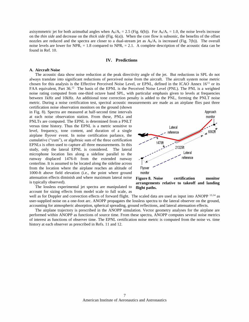
metric. During a noise certification test, spectral acoustic measurements are made as an airplane flies past three
certification noise observation monitors on the ground (shown
in Fig. 8). Spectra are measured at half-second time intervals
at each noise observation station. From these, PNLs and
PNLTs are computed. The EPNL is determined from a PNLT
versus time history. Thus the EPNL is a metric sensitive to
level, frequency, tone content, and duration of a single
airplane flyover event. In noise certification parlance, the
cumulative (“cum”), or algebraic sum of the three certification
EPNLs is often used to capture all three measurements. In this
study, only the lateral EPNL is considered. The lateral
microphone location lies along a sideline parallel to the
runway displaced 1476-ft from the extended runway
centerline. It is assumed to be located along the sideline across
from the location where the airplane reaches an altitude of
1000-ft above field elevation (i.e., the point where ground
attenuation effects diminish and where maximum lateral noise
is typically observed).
The lossless experimental jet spectra are manipulated to
account for sizing effects from model scale to full scale, as
well as for Doppler and convection effects of forward flight. The scaled data are used as input into ANOPP 13,14 as
user-supplied noise on a one-foot arc. ANOPP propagates the lossless spectra to the lateral observer on the ground,
accounting for atmospheric absorption, spherical spreading, ground reflections, and lateral attenuation effects.
The airplane trajectory is prescribed in the ANOPP simulation. Vector geometry analyses for the airplane are
performed within ANOPP as functions of source time. From these spectra, ANOPP computes several noise metrics
of interest as functions of observer time. The EPNL certification noise metric is computed from the noise vs. time
history at each observer as prescribed in Refs. 11 and 12.
Figure 8. Noise certification monitor
arrangements relative to takeoff and landing
flight paths.
American Institute of Aeronautics and Astronautics
8
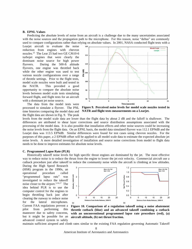
B. EPNL Values
Predicting the absolute levels of noise from an aircraft is a challenge due to the many uncertainties associated
with the noise sources and the propagation path to the microphone. For this reason, noise “deltas” are commonly
used to compare configurations rather than relying on absolute values. In 2001, NASA conducted flight tests with a
Learjet aircraft to evaluate the noise
reduction from engines with chevron
nozzles.15 The Lear 25 had two GE CJ610-6
turbojet engines that were clearly the
dominant noise source for high power
flyovers. During the 500-ft altitude
flyovers, one engine was throttled back
while the other engine was used to test
various nozzle configurations over a range
of throttle settings. Prior to the flight tests,
model scale nozzles were built and tested in
the NATR. This provided a good
opportunity to compare the absolute noise
levels between model scale tests simulating
forward flight, and flight tests for an aircraft
with a dominant jet noise source.
The data from the model tests were
processed to simulate a flyover. The PNL
time histories comparing the model data and
the flight data are shown in Fig. 9. The peak
levels from the model scale data are lower than the flight data by about 2 dB and the falloff is shallower. The
differences are attributed to shear layer corrections and source distribution assumptions associated with the
processing of the model data. It is also possible that installation effects and other noise sources could be increasing
the noise levels from the flight data. On an EPNL basis, the model data simulated flyover was 112.1 EPNdB and the
Learjet data was 113.5 EPNdB. Similar differences were found for test cases using chevron nozzles. For the
purposes of this paper, a 2 EPNdB offset will be applied to all model scale data to estimate the expected absolute jet
noise levels. A more detailed investigation of installation and source noise corrections from model to flight data
needs to be done to improve estimates for absolute noise levels.
C. Programmed Lapse Rate (PLR)
Historically takeoff noise levels for high specific thrust engines are dominated by the jet. The most effective
way to reduce noise is to reduce the thrust from the engine to lower the jet exit velocity. Commercial aircraft use a
cutback procedure just after takeoff to reduce the community noise while the aircraft is climbing at low altitudes.
During the High Speed Research
(HSR) program in the 1990s, an
operational procedure called
“programmed lapse rate” was
investigated to reduce the takeoff
noise closer to the airport.3,16,17 The
idea behind PLR is to use the
computer control for the engines to
begin throttling back just after
clearing the runway to reduce noise
for the lateral microphones.
Current FAA regulations prevent a
pilot from performing this
maneuver due to safety concerns,
but it might be possible for an
advanced control system to safely
maintain sufficient airspeed and climb rates similar to the existing FAA regulation governing Automatic Takeoff
Figure 9. Perceived noise levels for model scale nozzles tested in
NATR and flight tests measurements on a Learjet.
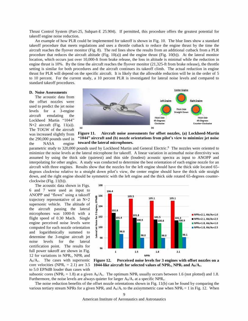
Figure 10. Comparison of a regulation takeoff using a noise abatement
throttle cutback (blue) and an advanced takeoff combining a cutback
with an unconventional programmed lapse rate procedure (red), (a)
aircraft altitude, (b) net thrust fraction.
American Institute of Aeronautics and Astronautics
9
Thrust Control System (Part-25, Subpart-E 25.904). If permitted, this procedure offers the greatest potential for
takeoff engine noise reduction.
An example of how PLR could be implemented for takeoff is shown in Fig. 10. The blue lines show a standard
takeoff procedure that meets regulations and uses a throttle cutback to reduce the engine thrust by the time the
aircraft reaches the flyover monitor (Fig. 8). The red lines show the results from an additional cutback from a PLR
procedure that reduces the aircraft altitude (Fig. 10(a)) and the engine thrust (Fig. 10(b)). At the lateral monitor
location, which occurs just over 10,000-ft from brake release, the loss in altitude is minimal while the reduction in
engine thrust is 10%. By the time the aircraft reaches the flyover monitor (21,325-ft from brake release), the throttle
setting is similar for both procedures and the aircraft continues its takeoff climb. The actual reduction in engine
thrust for PLR will depend on the specific aircraft. It is likely that the allowable reduction will be in the order of 5
to 10 percent. For the current study, a 10 percent PLR is investigated for lateral noise levels and compared to
standard takeoff procedures.
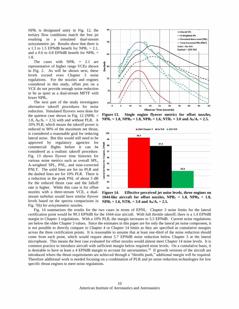
D. Noise Assessments
The acoustic data from
the offset nozzles were
used to predict the jet noise
levels for a 3-engine
aircraft emulating the
Lockheed Martin “1044”
N+2 aircraft (Fig. 11(a)).
The TOGW of the aircraft
was increased slightly from
the 290,000 pounds used in
the NASA engine
parametric study to 320,000 pounds used by Lockheed Martin and General Electric.8 The nozzles were oriented to
minimize the noise levels at the lateral microphone for takeoff. A linear variation in azimuthal noise directivity was
assumed by using the thick side (quietest) and thin side (loudest) acoustic spectra as input to ANOPP and
interpolating for other angles. A study was conducted to determine the best orientation of each engine nozzle for an
aircraft with three engines. Results show that the nozzles for the left engine should have the thick side located 65-
degrees clockwise relative to a straight down pilot’s view, the center engine should have the thick side straight
down, and the right engine should be symmetric with the left engine and the thick side rotated 65-degrees counter-
clockwise (Fig. 11(b)).
The acoustic data shown in Figs.
6 and 7 were used as input to
ANOPP and “flown” using a takeoff
trajectory representative of an N+2
supersonic vehicle. The altitude of
the aircraft passing the lateral
microphones was 1000-ft with a
flight speed of 0.30 Mach. Single
engine perceived noise levels were
computed for each nozzle orientation
and logarithmically summed to
determine the 3-engine aircraft jet
noise levels for the lateral
certification point. The results for
full power takeoff are shown in Fig.
12 for variations in NPRc, NPRt and
Ab/Ac. The cases with supersonic
core velocities (NPRc = 2.1) are 3.5
to 5.0 EPNdB louder than cases with
subsonic cores (NPRc = 1.8) at a given Ab/Ac. The optimum NPRt usually occurs between 1.6 (not plotted) and 1.8.
Furthermore, the noise levels are always quieter for larger Ab/Ac at a specific NPRc.
The noise reduction benefits of the offset nozzle orientations shown in Fig. 11(b) can be found by comparing the
various tertiary stream NPRs for a given NPRc and Ab/Ac to the axisymmetric case when NPRt = 1 in Fig. 12. When
Figure 11. Aircraft noise assessments for offset nozzles, (a) Lockheed-Martin
“1044” aircraft and (b) nozzle orientations from pilot’s view to minimize jet noise
toward the lateral microphones.
Figure 12. Perceived noise levels for 3 engines with offset nozzles on a
1044-like aircraft for selected values of NPRc, NPRt and Ab/Ac.
American Institute of Aeronautics and Astronautics
10
NPRt is designated unity in Fig. 12, the
tertiary flow conditions match the free jet
resulting in a simulated dual-stream
axisymmetric jet. Results show that there is
a 1.3 to 1.5 EPNdB benefit for NPRc = 2.1,
and a 0.6 to 0.8 EPNdB benefit for NPRc =
1.8.
The cases with NPRc = 2.1 are
representative of higher range VCEs shown
in Fig. 2. As will be shown next, these
levels exceed even Chapter 3 noise
regulations. For the nozzles and engines
considered in this study, offset jets on a
VCE do not provide enough noise reduction
to be as quiet as a dual-stream MFTF with
lower NPRc.
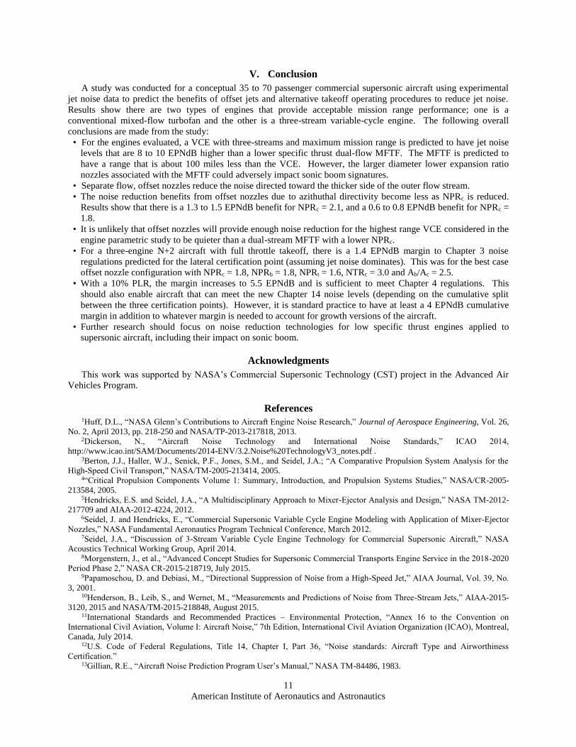
The next part of the study investigates
alternative takeoff procedures for noise
reduction. Simulated flyovers were done for
the quietest case shown in Fig. 12 (NPRc =
1.8, Ab/Ac = 2.5) with and without PLR. A
10% PLR, which means the takeoff power is
reduced to 90% of the maximum net thrust,
is considered a reasonable goal for reducing
lateral noise. But this would still need to be
approved by regulatory agencies for
commercial flights before it can be
considered as a realistic takeoff procedure.
Fig. 13 shows flyover time histories for
various noise metrics such as overall SPL,
A-weighted SPL, PNL, and tone-corrected
PNLT. The solid lines are for no PLR and
the dashed lines are for 10% PLR. There is
a reduction in the peak PNL of about 3 dB
for the reduced thrust case and the falloff
rate is higher. While this case is for offset
nozzles with a three-stream VCE, a dual-
stream turbofan would have similar flyover
levels based on the spectra comparisons in
Fig. 7(b) for axisymmetric nozzles.
Fig. 14 summarizes the results for the two cases in terms of EPNL. Chapter 3 noise limits for the lateral
certification point would be 99.3 EPNdB for the 1044-size aircraft. With full throttle takeoff, there is a 1.4 EPNdB
margin to Chapter 3 regulations. With a 10% PLR, the margin increases to 5.5 EPNdB. Current noise regulations
are below the older Chapter 3 values. Since the estimates in this paper are for only the lateral jet noise component, it
is not possible to directly compare to Chapter 4 or Chapter 14 limits as they are specified as cumulative margins
across the three certification points. It is reasonable to assume that at least one-third of the noise reduction should
come from each point, which would require about 5.7 EPNdB noise reduction below Chapter 3 at the lateral
microphone. This means the best case evaluated for offset nozzles would almost meet Chapter 14 noise levels. It is
common practice to introduce aircraft with sufficient margin below required noise levels. On a cumulative basis, it
is desirable to have at least a 4 EPNdB margin to account for uncertainties.18 If growth versions of the aircraft are
introduced where the thrust requirements are achieved through a “throttle push,” additional margin will be required.
Therefore additional work is needed focusing on a combination of PLR and jet noise reduction technologies for low
specific thrust engines to meet noise regulations.
Figure 14. Effective perceived jet noise levels, three engines on
1044-like aircraft for offset nozzles, NPRc = 1.8, NPRb = 1.8,
NPRt = 1.6, NTRc = 3.0 and Ab/Ac = 2.5.
Figure 13. Single engine flyover metrics for offset nozzles,
NPRc = 1.8, NPRb = 1.8, NPRt = 1.6, NTRc = 3.0 and Ab/Ac = 2.5.
American Institute of Aeronautics and Astronautics
11
V. Conclusion
A study was conducted for a conceptual 35 to 70 passenger commercial supersonic aircraft using experimental
jet noise data to predict the benefits of offset jets and alternative takeoff operating procedures to reduce jet noise.
Results show there are two types of engines that provide acceptable mission range performance; one is a
conventional mixed-flow turbofan and the other is a three-stream variable-cycle engine. The following overall
conclusions are made from the study:
• For the engines evaluated, a VCE with three-streams and maximum mission range is predicted to have jet noise
levels that are 8 to 10 EPNdB higher than a lower specific thrust dual-flow MFTF. The MFTF is predicted to
have a range that is about 100 miles less than the VCE. However, the larger diameter lower expansion ratio
nozzles associated with the MFTF could adversely impact sonic boom signatures.
• Separate flow, offset nozzles reduce the noise directed toward the thicker side of the outer flow stream.
• The noise reduction benefits from offset nozzles due to azithuthal directivity become less as NPRc is reduced.
Results show that there is a 1.3 to 1.5 EPNdB benefit for NPRc = 2.1, and a 0.6 to 0.8 EPNdB benefit for NPRc =
1.8.
• It is unlikely that offset nozzles will provide enough noise reduction for the highest range VCE considered in the
engine parametric study to be quieter than a dual-stream MFTF with a lower NPRc.
• For a three-engine N+2 aircraft with full throttle takeoff, there is a 1.4 EPNdB margin to Chapter 3 noise
regulations predicted for the lateral certification point (assuming jet noise dominates). This was for the best case
offset nozzle configuration with NPRc = 1.8, NPRb = 1.8, NPRt = 1.6, NTRc = 3.0 and Ab/Ac = 2.5.
• With a 10% PLR, the margin increases to 5.5 EPNdB and is sufficient to meet Chapter 4 regulations. This
should also enable aircraft that can meet the new Chapter 14 noise levels (depending on the cumulative split
between the three certification points). However, it is standard practice to have at least a 4 EPNdB cumulative
margin in addition to whatever margin is needed to account for growth versions of the aircraft.
• Further research should focus on noise reduction technologies for low specific thrust engines applied to
supersonic aircraft, including their impact on sonic boom.
Acknowledgments
This work was supported by NASA’s Commercial Supersonic Technology (CST) project in the Advanced Air
Vehicles Program.
References 1Huff, D.L., “NASA Glenn’s Contributions to Aircraft Engine Noise Research,” Journal of Aerospace Engineering, Vol. 26,
No. 2, April 2013, pp. 218-250 and NASA/TP-2013-217818, 2013. 2Dickerson, N., “Aircraft Noise Technology and International Noise Standards,” ICAO 2014,
http://www.icao.int/SAM/Documents/2014-ENV/3.2.Noise%20TechnologyV3_notes.pdf . 3Berton, J.J., Haller, W.J., Senick, P.F., Jones, S.M., and Seidel, J.A.; “A Comparative Propulsion System Analysis for the
High-Speed Civil Transport,” NASA/TM-2005-213414, 2005. 4“Critical Propulsion Components Volume 1: Summary, Introduction, and Propulsion Systems Studies,” NASA/CR-2005-
213584, 2005. 5Hendricks, E.S. and Seidel, J.A., “A Multidisciplinary Approach to Mixer-Ejector Analysis and Design,” NASA TM-2012-
217709 and AIAA-2012-4224, 2012. 6Seidel, J. and Hendricks, E., “Commercial Supersonic Variable Cycle Engine Modeling with Application of Mixer-Ejector
Nozzles,” NASA Fundamental Aeronautics Program Technical Conference, March 2012. 7Seidel, J.A., “Discussion of 3-Stream Variable Cycle Engine Technology for Commercial Supersonic Aircraft,” NASA
Acoustics Technical Working Group, April 2014. 8Morgenstern, J., et al., “Advanced Concept Studies for Supersonic Commercial Transports Engine Service in the 2018-2020
Period Phase 2,” NASA CR-2015-218719, July 2015. 9Papamoschou, D. and Debiasi, M., “Directional Suppression of Noise from a High-Speed Jet,” AIAA Journal, Vol. 39, No.
3, 2001. 10Henderson, B., Leib, S., and Wernet, M., “Measurements and Predictions of Noise from Three-Stream Jets,” AIAA-2015-
3120, 2015 and NASA/TM-2015-218848, August 2015. 11International Standards and Recommended Practices – Environmental Protection, “Annex 16 to the Convention on
International Civil Aviation, Volume I: Aircraft Noise,” 7th Edition, International Civil Aviation Organization (ICAO), Montreal,
Canada, July 2014. 12U.S. Code of Federal Regulations, Title 14, Chapter I, Part 36, “Noise standards: Aircraft Type and Airworthiness
Certification.” 13Gillian, R.E., “Aircraft Noise Prediction Program User’s Manual,” NASA TM-84486, 1983.
American Institute of Aeronautics and Astronautics
12
14Zorumski, W.E., “Aircraft Noise Prediction Program Theoretical Manual, Parts 1 and 2,” NASA TM-83199, 1982; Latest
revision: Level 31. 15Brown, C. and Bridges, J, “An Analysis of Model Scale Data Transformation to Full Scale Flight Using Chevron Nozzles,”
NASA TM-2003-212732, 2003. 16Shaw, R.J., Gilkey, S., and Hines, R., “Engine Technology Challenges for a 21st Century High-Speed Civil Transport,”
NASA TM-106216, 1993. 17Jackson, E.B., Raney, D.L., Glaab, L.J., and Derry, S.D., “Piloted Simulation Assessment of a High-Speed Civil Transport
Configuration, “NASA TP-2002-211441, 2002. 18Huff, D.L. et al., “Report to CAEP by the CAEP Noise Technology Independent Expert Panel: Novel aircraft noise
technology review and medium and long term noise reduction goals,” ICAO, Doc 10017, 2014.