Embed Size (px)
Citation preview
Eurographics Symposium on Rendering 2012Fredo Durand and Diego Gutierrez(Guest Editors)
Volume 31 (2012), Number 4
Per-Vertex Defocus Blur for Stochastic Rasterization
Jacob Munkberg1 Robert Toth1 Tomas Akenine-Möller1,2
1Intel Corporation 2Lund University
AbstractWe present user-controllable and plausible defocus blur for a stochastic rasterizer. We modify circle of confusioncoefficients per vertex to express more general defocus blur, and show how the method can be applied to limitthe foreground blur, extend the in-focus range, simulate tilt-shift photography, and specify per-object defocus blur.Furthermore, with two simplifying assumptions, we show that existing triangle coverage tests and tile culling testscan be used with very modest modifications. Our solution is temporally stable and handles simultaneous motionblur and depth of field.
Categories and Subject Descriptors (according to ACM CCS): I.3.3 [Computer Graphics]: Picture/ImageGeneration—Display algorithms
1. Introduction
Digital artists and game developers often want non-physically-based control over depth of field (DOF) param-eters. Examples include the possibility to limit foregroundblur or to extend the in-focus range while preserving theforeground and background blur. With post-processed DOFapproaches [PC81, Dem04, EH07], this is straightforwardsince the blur filter is expressed as a user-provided functionof the scene depth. Kosara et al. [KMH01] introduce the termsemantic depth of field, where the amount of DOF is con-trolled on a per-object basis. Their implementation use a setof depth-sorted layers or billboards, which are individuallyblurred and composited into a final image. However, visibil-ity is never resolved correctly using the above methods, andconsequently, their use is limited.
A physically-based camera model can be simulated withdistributed ray tracing through a set of lenses and aper-tures [KMH95]. Kosloff and Barsky [KB09] use non-linearray tracing (by tracing bent rays) to simulate non-physicaleffects such as multiple focus planes. Each pixel may havea unique ray distribution. In general, each point in 3D spacecan have a different blur value. They also present two otherapproaches for generalized DOF: a heat diffusion solver ona layered depth image and a light field filtering technique.
Lee et al.’s work [LES10] on flexible defocus blur allowsfor varying lens parameters for each pixel to emulate ef-fects like tilt-shift photography, curvature of confusion, andlens aberrations. Visibility is resolved by ray tracing througha layered depth image. User-provided camera space DOFconstraints are interpolated using a least-squares fit to de-rive varying per-pixel lens parameters. We refer to Lee et
al.’s paper for an overview of lens effects and a more com-plete survey of controllable defocus techniques. It is far fromstraightforward to extend these ray tracing approaches tohandle simultaneous motion blur and depth of field.
State-of-the-art stochastic rasterizers, e.g., Render-Man [AG00], have programmable surface and displacementshading, and extensive global camera control, where theaperture shape and density can be adjusted. To the best ofour knowledge, however, there is no publicly known flexibleDOF approach for stochastic rasterizers with local control,such that the blur amount can be controlled per-vertex.
Our goal is flexible DOF that works directly in a stochas-tic rasterizer without any layer-generation passes, iterativesolvers, and with minimal impact on pipeline design andrendering optimizations. Specifically, we want to explorehow user-defined DOF control can be integrated with ef-ficient tile-based traversal for higher-dimensional rasteriza-tion [LAKL11, AMTMH12, MAM12].
We let the user specify circle of confusion parameters forevery vertex in a mesh. This enables artistic control of defo-cus blur, while still supporting the standard thin lens modelas a subset. In addition, we introduce two simplifying as-sumptions that makes this approach compatible with state-of-the-art per-tile tests and coverage tests in 4D and 5D ras-terizers, and handles simultaneous motion blur and DOF.The streaming nature of rasterization also enables interest-ing features, such as per-triangle DOF control and reducedDOF for specific depth ranges, which are not easily sup-ported by ray tracing-based approaches. Finally, we showthat our model is also a useful tool to reduce performancevariations for scenes rendered with defocus blur.
c© 2012 The Author(s)Computer Graphics Forum c© 2012 The Eurographics Association and Blackwell Publish-ing Ltd. Published by Blackwell Publishing, 9600 Garsington Road, Oxford OX4 2DQ,UK and 350 Main Street, Malden, MA 02148, USA.
DOI: 10.1111/j.1467-8659.2012.03133.x
J. Munkberg & R. Toth & T. Akenine-Möller / Per-Vertex Defocus Blur for Stochastic Rasterization
C
w
α
Cs
|Cs|
w
α
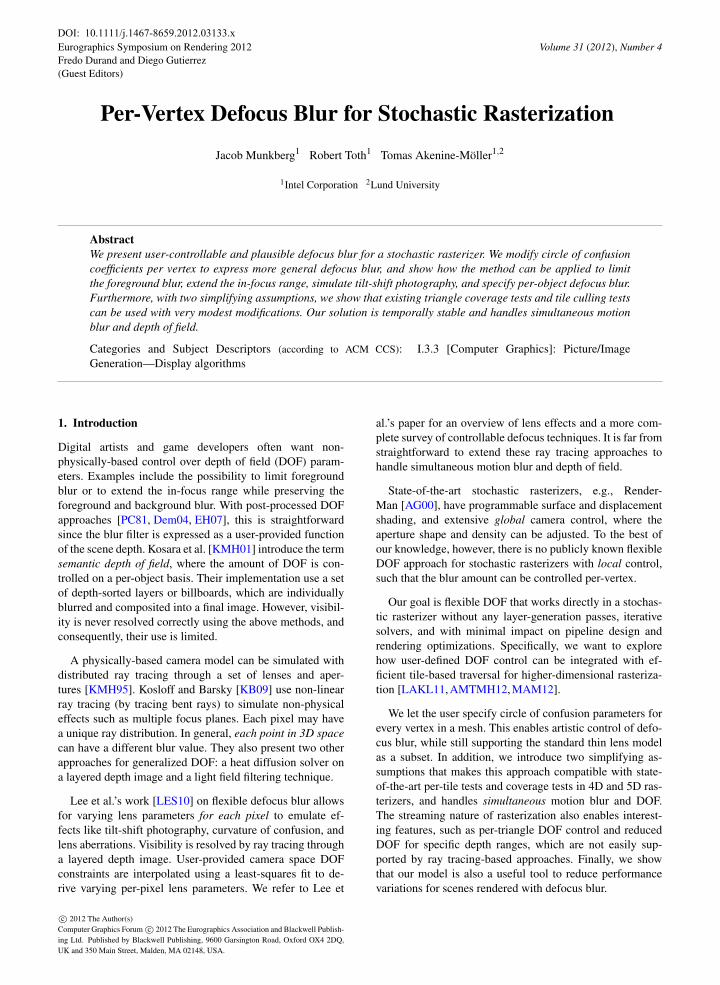
Figure 1: Circle of confusion radius in clip space (left) andscreen space (right). The bright yellow curves show the func-tions obtained by the thin lens model. The dark blue curvesshow the functions obtained after limiting the foregroundblur.
C
wCi
Cj
Figure 2: Linearization errors are introduced for trianglesthat span discontinuities in C.
2. Algorithm
Let us first revisit the standard assumptions of a stochasticrasterizer. A clip-space vertex of a triangle is denoted p =(x,y,w). In the thin lens model, the signed clip-space circleof confusion radius, C, for p is a linear function of the vertexdepth, w, i.e., C(w) = a+wb, where a and b are constantsderived from the camera’s aperture size and focal distance.The clip space vertex position for a specific lens position,(u,v), is given by: p′(u,v) = p+C(w)(u,k v,0), which is ashear in clip space x and y. The scalar, k, adjusts for non-square aspect ratios, and the focus plane is located at w = F .
The screen space blur radius, Cs =C/w, goes towards in-finity for w→ 0, so a small out-of-focus object very closeto the camera can easily cover the entire screen. This is incontrast to most post-processing DOF methods, where thescreen space defocus blur is limited to a certain max radius,which is physically incorrect, but has more predictable per-formance.
Example As an illustrative example, we limit the screenspace blur, Cs(w) = (a+wb)/w, to a certain radius, R, inthe foreground region (w < F). We see that Cs(w) = R forthe depth w = a
R−b . The threshold is denoted α = aR−b . This
leads to the following definitions:
Cs =
{ a+wbw , w > α,
R w≤ α,(1)
which is equivalent to the following formula in clip space:
C =
{a+wb, w > α,wR w≤ α.
(2)
Equations 1 and 2 are illustrated in Figure 1.
C is a piecewise linear function of the vertex depth, andthe thin lens property that C can be linearly interpolated overthe triangle does not hold. Therefore, we introduce the as-sumption that the clip space circle of confusion radius is lin-ear in the interior of a triangle. With this assumption, wecan compute C in the vertex shader using Equation 2 andprovide these coefficients instead of the global camera pa-rameters when positioning and coverage-testing the trianglefor a certain lens position. The stochastic rasterizer is es-sentially unmodified, and the amount of defocus blur is nowan attribute that can be controlled on vertex granularity foradded artistic control.
Any triangle straddling the discontinuity in C will have asomewhat different circle of confusion in the interior thanwhat is described by the piecewise linear C function, as il-lustrated in Figure 2. This effect is most visible on very largetriangles, and is negligible in a micropolygon pipeline. Also,geometry with T-junctions may show cracks with this as-sumption. We see this as yet another reason to completelyavoid T-junctions.
2.1. Controllable Defocus Blur in 5D Rasterization
In this section, we generalize the user-controllable DOFto 5D stochastic rasterization, where the fifth dimension isshutter time. We assume linear vertex motion in clip space,i.e., p(t) = (1−t)q+tr. With the thin lens model, the signedclip space circle of confusion radius, C, of a moving vertex,p(t), is a linear function in t: C(t) = C(w(t)) = a+w(t)b.The clip space vertex position for a time, t, and lens posi-tion, uv, is given by:
p′(u,v, t) = p(t)+C(t)(u,k v,0). (3)
If C is replaced by a non-linear function in t, efficient trian-gle coverage tests (per tile and per sample) in 5D no longerwork. We therefore introduce another simplification, namelythat the clip space circle of confusion radius of a vertex isa linear function in time within the frame. The user pro-vides two circle of confusion coefficients for each vertex perframe, namely c0 at t = 0 and c1 at t = 1. During rasteriza-tion, we use C(t) = (1−t)c0+tc1 to determine the triangle’sposition for a time, t, and lens position, uv, in Equation 3.If the user provides the standard thin lens coefficients, e.g.,c0 = a+b w(0) and c1 = a+b w(1), the rendered image isidentical to that of a standard 5D rasterizer.
3. Pipeline Modifications
In this section, we outline pipeline differences between arasterizer where the clip space circle of confusion, C, is auser-provided vertex attribute compared to a rasterizer thatassumes a thin lens model.
The sample coverage test of a stochastic rasterizer can beslightly optimized if C is a linear function of w. Comparedto a test that handles arbitrary C-coefficients, the difference
c© 2012 The Author(s)c© 2012 The Eurographics Association and Blackwell Publishing Ltd.
1386
J. Munkberg & R. Toth & T. Akenine-Möller / Per-Vertex Defocus Blur for Stochastic Rasterization
in arithmetic cost is 16 vs. 18 FMA (fused-multiply add) op-erations for a DOF coverage test. For a 5D coverage test, thedifference is 25 vs. 30 FMA operations [LK11a].
Some stochastic rasterizers also perform coverage tests in5D per tile to quickly discard samples that cannot hit the tri-angle. It is easy to verify that the tile culling tests from previ-ous work [LAKL11,AMTMH12,MAM12] still work as longas C varies linearly over the triangle and varies linearly in twithin the frame, which are exactly the two assumptions weintroduced in Section 2. The same holds for view-frustumculling and screen space bounding. For example, Laine andKarras’ screen space bound algorithm [LK11b] works out ofthe box with user-provided C-coefficients.
A backface culling test for 5D rasterization [MAM11]can be optimized for the thin lens model. We show the ex-pression for a generalized backface test that supports user-provided C-coefficients in Appendix A and compare it to thethin-lens version.
4. Results
For all images in this section, we have simply averaged allsamples within a pixel. No motion or defocus-aware recon-struction filters were used. Also, we deliberately use high-contrast shading to more easily see the effect of the blur.
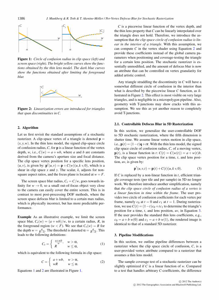
With arbitrary circle of confusion parameters, it is possi-ble to accomplish a wide variety of defocus effects. Figure 3shows frames from a sequence where the foreground blur isreduced (Section 2). Figure 4 shows reduced foreground blurin a scene with simultaneous motion blur and DOF (Sec-tion 2.1). In our experience, the transition from large blur tono foreground blur looks plausible. The in-focus range canbe extended by another piecewise linear C(w) function, asshown in Figure 5.
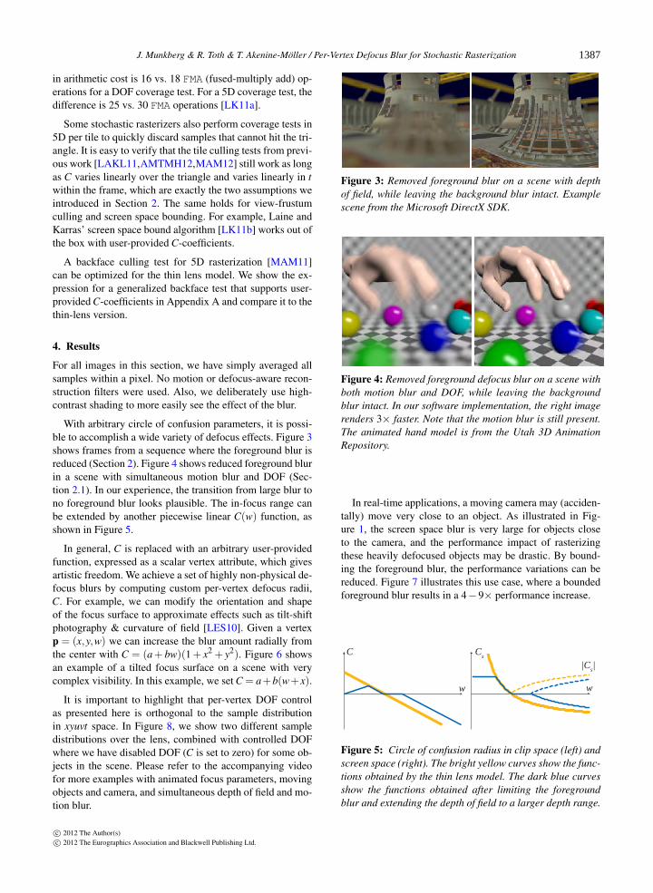
In general, C is replaced with an arbitrary user-providedfunction, expressed as a scalar vertex attribute, which givesartistic freedom. We achieve a set of highly non-physical de-focus blurs by computing custom per-vertex defocus radii,C. For example, we can modify the orientation and shapeof the focus surface to approximate effects such as tilt-shiftphotography & curvature of field [LES10]. Given a vertexp = (x,y,w) we can increase the blur amount radially fromthe center with C = (a+ bw)(1+ x2 + y2). Figure 6 showsan example of a tilted focus surface on a scene with verycomplex visibility. In this example, we set C = a+b(w+x).
It is important to highlight that per-vertex DOF controlas presented here is orthogonal to the sample distributionin xyuvt space. In Figure 8, we show two different sampledistributions over the lens, combined with controlled DOFwhere we have disabled DOF (C is set to zero) for some ob-jects in the scene. Please refer to the accompanying videofor more examples with animated focus parameters, movingobjects and camera, and simultaneous depth of field and mo-tion blur.
Figure 3: Removed foreground blur on a scene with depthof field, while leaving the background blur intact. Examplescene from the Microsoft DirectX SDK.
Figure 4: Removed foreground defocus blur on a scene withboth motion blur and DOF, while leaving the backgroundblur intact. In our software implementation, the right imagerenders 3× faster. Note that the motion blur is still present.The animated hand model is from the Utah 3D AnimationRepository.
In real-time applications, a moving camera may (acciden-tally) move very close to an object. As illustrated in Fig-ure 1, the screen space blur is very large for objects closeto the camera, and the performance impact of rasterizingthese heavily defocused objects may be drastic. By bound-ing the foreground blur, the performance variations can bereduced. Figure 7 illustrates this use case, where a boundedforeground blur results in a 4−9× performance increase.
C
w w
Cs
|Cs|
Figure 5: Circle of confusion radius in clip space (left) andscreen space (right). The bright yellow curves show the func-tions obtained by the thin lens model. The dark blue curvesshow the functions obtained after limiting the foregroundblur and extending the depth of field to a larger depth range.
c© 2012 The Author(s)c© 2012 The Eurographics Association and Blackwell Publishing Ltd.
1387
J. Munkberg & R. Toth & T. Akenine-Möller / Per-Vertex Defocus Blur for Stochastic Rasterization
tilted focal surface no foreground blurFigure 6: Examples with complex visibility. Hairball modelfrom Samuli Laine.
2k
0
Reference (1.0) Large bound (0.24) Small bound (0.11)
Figure 7: Defocused foreground triangles cover large screenspace regions. We visualize the number of triangles pro-cessed per pixel as heat maps. The numbers in parenthesesindicate relative render times compared to the reference in asoftware stochastic rasterizer. Bounding the foreground blurreduces the work substantially. Animated wood doll from theUtah 3D Animation Repository.
4.1. Discussion
In a rasterizer, the per-vertex circle of confusion parameter,C, simply indicates how much an object should be shearedfor a specific lens coordinate, and is an object-specific pa-rameter. In a ray tracer, however, the geometry is expressedin a global coordinate system, and individual shears per ob-ject mean that the distribution and angles of rays from thecamera lens are unique for each triangle. This would requiresending “bent rays” through the scene, which makes theray traversal step much more complicated. See Kosloff andBarsky’s work [KB09] for more details of non-linear dis-tributed ray tracing. Some special cases, like limiting fore-ground blur can be handled as shown in Figure 9, using aunique lens per screen space sample, that is inserted in thescene. This is cumbersome, and is very likely to completelydisable certain traversal optimizations for primary rays. Astochastic rasterizer, on the other hand, handles these caseseasily with our algorithm, with none or very modest perfor-mance implications.
reference flexible
Figure 8: Our flexible DOF approach is orthogonal to thelens sample distribution. Here is an example with circular(top) & hexagonal (bottom) lens shape combined with per-vertex control of the blur amount.
y
w
α F1
y
w
α F1w=0 w=0
p
p
LL
Figure 9: Limiting foreground blur in a ray tracer. Theglobal lens is replaced by a per-pixel lens, L′ (red), insertedat depth w = α, centered around the ray through the pixeland the pinhole camera. Its focal length, f = F
α(F−α), is cho-
sen such that the blur in the region w > α is unaffected. Raysare now traced from a pinhole camera at w = 0 towards thelens and each live ray is refracted in the lens. This is shownfor two different points, p, on the image plane.
On the other hand, in a rasterizer designed around thethin-lens model, it is hard to simulate effects that vary asfunctions of the position on the lens, such as general lensaberrations. Our extension with user-provided C-coefficientsper vertex only modifies the amount the vertex is sheared inx and y in clip space, and is assumed to be a linear functionin u and v, where the shears in x and y are independent. Thatsaid, the rasterizer could be extended with more defocus pa-rameters per vertex, defining the coefficients of a functionC = f (u,v, t) to support more elaborate lens models. Thiswould, however, complicate the coverage and cull tests sig-nificantly. Note also that with arbitrary C parameters, the in-tegral of the view-dependent shading contribution from alllens samples may differ from the thin-lens equivalent in out-of-focus regions.
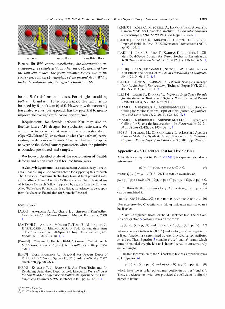
A difficult scenario for user-defined blur per-vertex is alarge triangle spanning the focus plane. When gradually re-ducing the foreground blur, the focus distance appears tomove. This is an effect of the assumption that the defocusblur varies linearly over the triangle (e.g., Figure 2). Withhigher tessellation rates, this effect is hardly noticeable, asshown in Figure 10.
It is important to note that it is hard to guarantee an upper
c© 2012 The Author(s)c© 2012 The Eurographics Association and Blackwell Publishing Ltd.
1388
J. Munkberg & R. Toth & T. Akenine-Möller / Per-Vertex Defocus Blur for Stochastic Rasterization
reference coarse floor tessellated floor
Figure 10: With coarse tessellation, the linearization as-sumption gives visible artifacts when the CoCs deviated fromthe thin-lens model. The focus distance moves due to thecoarse tessellation (2 triangles) of the ground floor. With ahigher tessellation rate, this effect is hardly visible.
bound, R, for defocus in all cases. For triangles straddlingboth w = 0 and w = F , the screen space blur radius is notbounded by R as C(w = 0) 6= 0. However, with reasonablytessellated scenes, our approach has the potential to greatlyimprove the average rasterization performance.
Requirements for flexible defocus blur may also in-fluence future API designs for stochastic rasterizers. Wewould like to see an output variable from the vertex shader(OpenGL/Direct3D) or surface shader (RenderMan) repre-senting the defocus coefficients. The user then has the optionto override the global camera parameters when the primitiveis bounded, positioned, and sampled.
We leave a detailed study of the combination of flexibledefocus and reconstruction filters for future work.
Acknowledgements The authors thank Aaron Coday, Tom Pi-azza, Charles Lingle, and Aaron Lefohn for supporting this research.The Advanced Rendering Technology team at Intel provided valu-able feedback. Tomas Akenine-Möller is a Royal Swedish Academyof Sciences Research Fellow supported by a grant from the Knut andAlice Wallenberg Foundation. In addition, we acknowledge supportfrom the Swedish Foundation for Strategic Research.
References
[AG00] APODACA A. A., GRITZ L.: Advanced RenderMan:Creating CGI for Motion Pictures. Morgan Kaufmann, 2000.1
[AMTMH12] AKENINE-MÖLLER T., TOTH R., MUNKBERG J.,HASSELGREN J.: Efficient Depth of Field Rasterization usinga Tile Test based on Half-Space Culling. Computer GraphicsForum, 31, 1 (2012), 3–18. 1, 3
[Dem04] DEMERS J.: Depth of Field: A Survey of Techniques. InGPU Gems, Fernando R., (Ed.). Addison-Wesley, 2004, pp. 375–390. 1
[EH07] EARL HAMMON J.: Practical Post-Process Depth ofField. In GPU Gems 3, Nguyen H., (Ed.). Addison-Wesley, 2007,chapter 28, pp. 583–606. 1
[KB09] KOSLOFF T. J., BARSKY B. A.: Three Techniques forRendering Generalized Depth of Field Effects. In Proceedings ofthe Fourth SIAM Conference on Mathematics for Industry: Chal-lenges and Frontiers (MI09) (October 2009), pp. 42–48. 1, 4
[KMH95] KOLB C., MITCHELL D., HANRAHAN P.: A RealisticCamera Model for Computer Graphics. In Computer Graphics(Proceedings of SIGGRAPH 95) (1995), pp. 317–324. 1
[KMH01] KOSARA R., MIKSCH S., HAUSER H.: SemanticDepth of Field. In Proc. IEEE Information Visualization (2001),pp. 97–104. 1
[LAKL11] LAINE S., AILA T., KARRAS T., LEHTINEN J.: Cli-pless Dual-Space Bounds for Faster Stochastic Rasterization.ACM Transactions on Graphics, 30, 4 (2011), 106:1–106:6. 1,3
[LES10] LEE S., EISEMANN E., SEIDEL H.-P.: Real-Time LensBlur Effects and Focus Control. ACM Transactions on Graphics,29, 4 (2010), 65:1–7. 1, 3
[LK11a] LAINE S., KARRAS T.: Efficient Triangle CoverageTests for Stochastic Rasterization. Technical Report NVR-2011-003, NVIDIA, Sept. 2011. 3
[LK11b] LAINE S., KARRAS T.: Improved Dual-Space Boundsfor Simultaneous Motion and Defocus Blur. Technical ReportNVR-2011-004, NVIDIA, Nov. 2011. 3
[MAM11] MUNKBERG J., AKENINE-MÖLLER T.: BackfaceCulling for Motion Blur and Depth of Field. journal of graphics,gpu, and game tools 15, 2 (2011), 123–139. 3, 5
[MAM12] MUNKBERG J., AKENINE-MÖLLER T.: HyperplaneCulling for Stochastic Rasterization. In Eurographics 2012 -Short Papers (2012), pp. 105–108. 1, 3
[PC81] POTMESIL M., CHAKRAVARTY I.: A Lens and ApertureCamera Model for Synthetic Image Generation. In ComputerGraphics (Proceedings of SIGGRAPH 81) (1981), pp. 297–305.1
Appendix A - 5D Backface Test for Flexible Blur
A backface culling test for DOF [MAM11] is expressed as a deter-minant test:
p′0(u,v) · (p′1(u,v)×p′2(u,v)) > 0, (4)
where p′i (u,v) = pi +Ci(u,kv,0). This can be expanded to:
p0 ·(p1×p2)+(u,k v,0) ·(C0p1×p2+C1p2×p0+C2p0×p1)> 0.(5)
If C follows the thin lens model, e.g., Ci = a+ bwi, the expressioncan be simplified to:
p0 · (p1×p2)+a(u,kv,0) · (p0×p1 +p1×p2 +p2×p0)> 0. (6)
For user-provided C-coefficients, this optimization must of coursebe disabled.
A similar argument holds for the 5D backface test. The 5D ver-sion of Equation 5 contains terms on the form:
p0(t) · (p1(t)×p2(t)) and (u,k v,0) · (Cm(t)pn(t)×po(t)), (7)
where m,n,o are indices in {0,1,2} and each Cm = (1−t)c0+tc1 isa linear function in t determined by user-provided vertex attributesc0 and c1. Thus, Equation 7 contains t3, ut3, and vt3 terms, whichmust be bounded over the lens and shutter interval to conservativelycull a triangle.
The thin lens version of the 5D backface test has simplified terms(c.f., Equation 6):
p0(t) · (p1(t)×p2(t)) and a(u,k v,0) · (pn(t)×po(t)). (8)
which have lower order polynomial coefficients t3, ut2 and vt2.Thus, a backface test with user-provided C-coefficients is slightlyharder to bound.
c© 2012 The Author(s)c© 2012 The Eurographics Association and Blackwell Publishing Ltd.
1389


![Rasterization - University of Southern Californiabarbic.usc.edu/cs420-s20/14-rasterization/14... · 2020. 3. 22. · Rasterization Scan Conversion Antialiasing [Angel Ch. 6] 1 2 Rasterization](https://img.pdfslide.us/doc/110x75/5fe10f71a248041af453f5e3/rasterization-university-of-southern-2020-3-22-rasterization-scan-conversion.jpg)