Embed Size (px)
Citation preview
The Goal : Visual Complexity
• We would like to dynamically compute the lighting for every single pixel on the screen each frame
• The lighting should be able to change abruptly on a per-pixel basis

Per-Pixel Lighting Example Shot
Pixel–Sized Triangles?
• One way to achieve this would be to perform vertex lighting on pixel-sized triangles• Pixar subdivides down to ½ pixel triangles
• A Per-pixel triangle gives• A position• A direction normal • A color
At each point on the screen. That allows performing classic vertex lighting at each pixel of the screen

Pixel-Sized Triangles Cost
• Well, why not use per-pixel triangles?
• You could, but you would have to tessellate every surface each frame exactly to a pixel to avoid wasting triangles
• Besides, the T&L would kill you
• The amount of memory to store the triangles would be another issue
Alternatives
• Due to these factors, it is undesirable to have pixel-sized triangles, but it turns out we alreadyhave a primitive we can use that can scale almost exactly 1 to 1 with pixels…
• The Texel!
• When properly mip-mapped, there can be one ( albeit filtered ) texel for each pixel on the screen
Enter the Texel
• People have been using Texels for Shading for quite a while – but not for calculating Lighting.
• Texel Shading techniques, such as lightmaps, store pre-computed lighting on a per-pixel basis
• Texel Lighting recalculates all or part of the lighting equation on a per-pixel basis, thus allowing dynamic lighting on a per-pixel basis
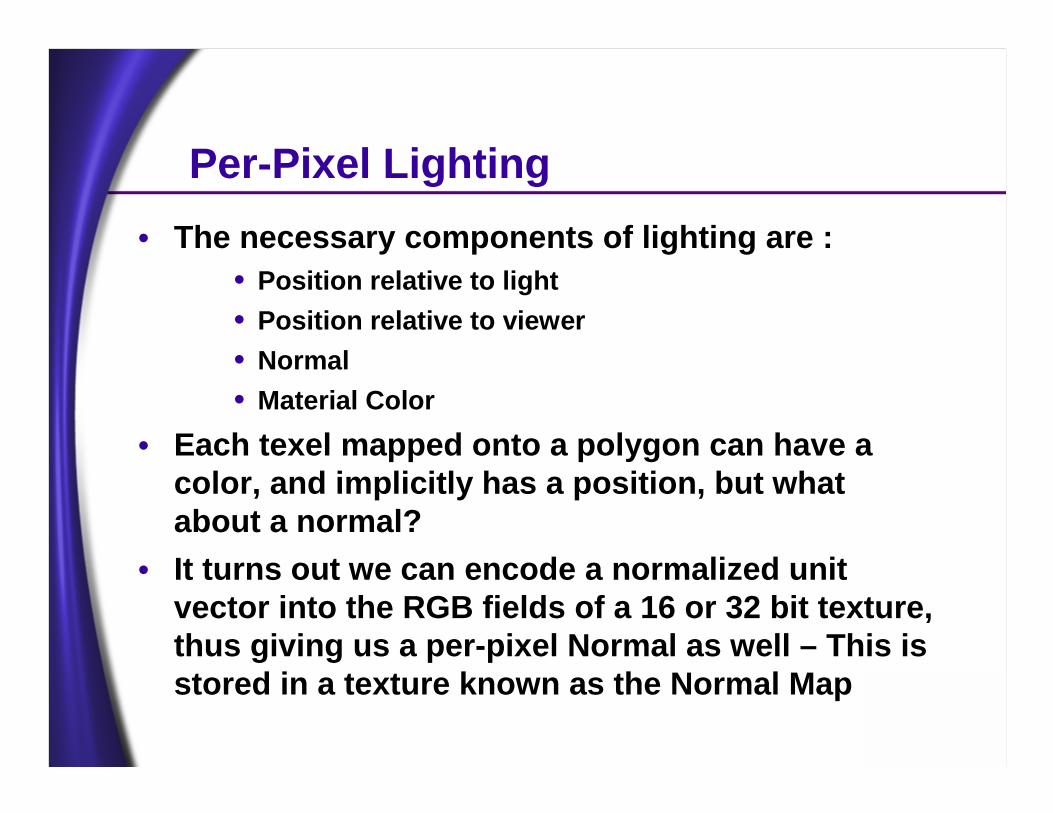
Per-Pixel Lighting• The necessary components of lighting are :
• Position relative to light• Position relative to viewer• Normal• Material Color
• Each texel mapped onto a polygon can have a color, and implicitly has a position, but what about a normal?
• It turns out we can encode a normalized unit vector into the RGB fields of a 16 or 32 bit texture, thus giving us a per-pixel Normal as well – This is stored in a texture known as the Normal Map
Per-Pixel Lighting
• Given a position, color, and RGB-encoded normal we can exactly duplicate diffuse directional lighting using the D3DTOP_DOTPRODUCT3 texture blending operation
• Specular lights can be achieved, as well as spotlights
• Point lights can be implemented as well
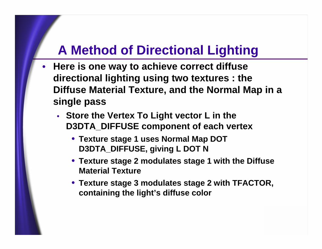
A Method of Directional Lighting• Here is one way to achieve correct diffuse
directional lighting using two textures : the Diffuse Material Texture, and the Normal Map in a single pass• Store the Vertex To Light vector L in the
D3DTA_DIFFUSE component of each vertex• Texture stage 1 uses Normal Map DOT
D3DTA_DIFFUSE, giving L DOT N• Texture stage 2 modulates stage 1 with the Diffuse
Material Texture• Texture stage 3 modulates stage 2 with TFACTOR,
containing the light’s diffuse color
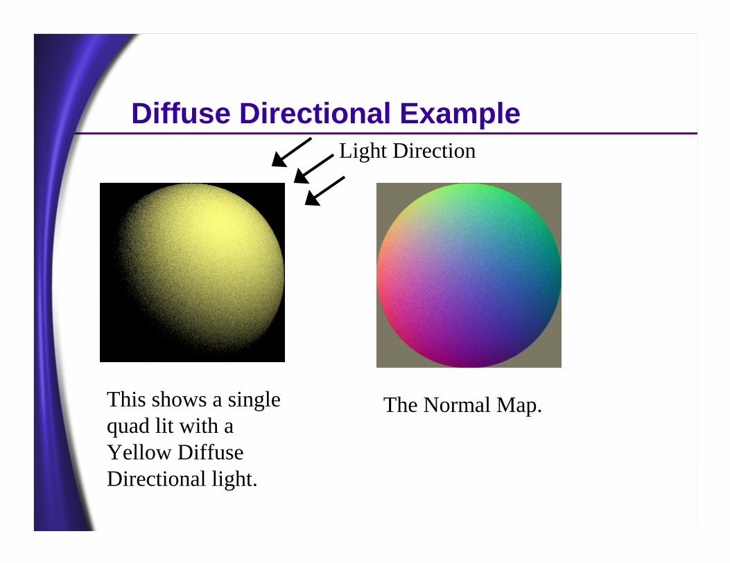
Diffuse Directional Example
This shows a single quad lit with a Yellow Diffuse Directional light.
The Normal Map.
Light Direction
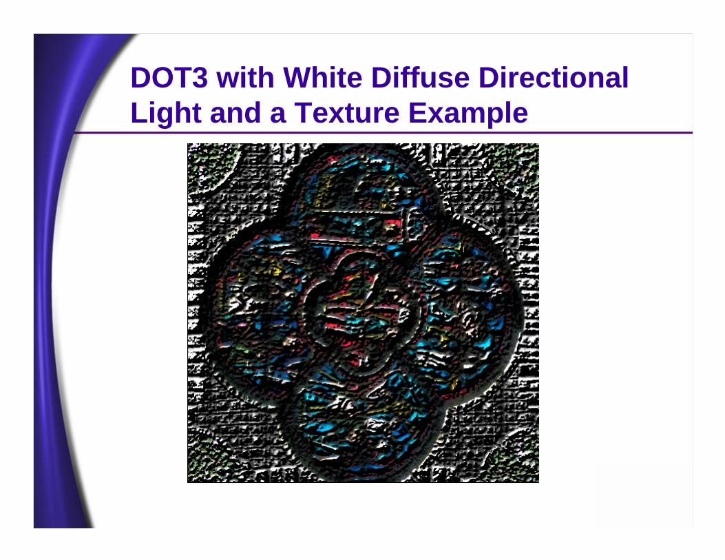
DOT3 with White Diffuse Directional Light and a Texture Example
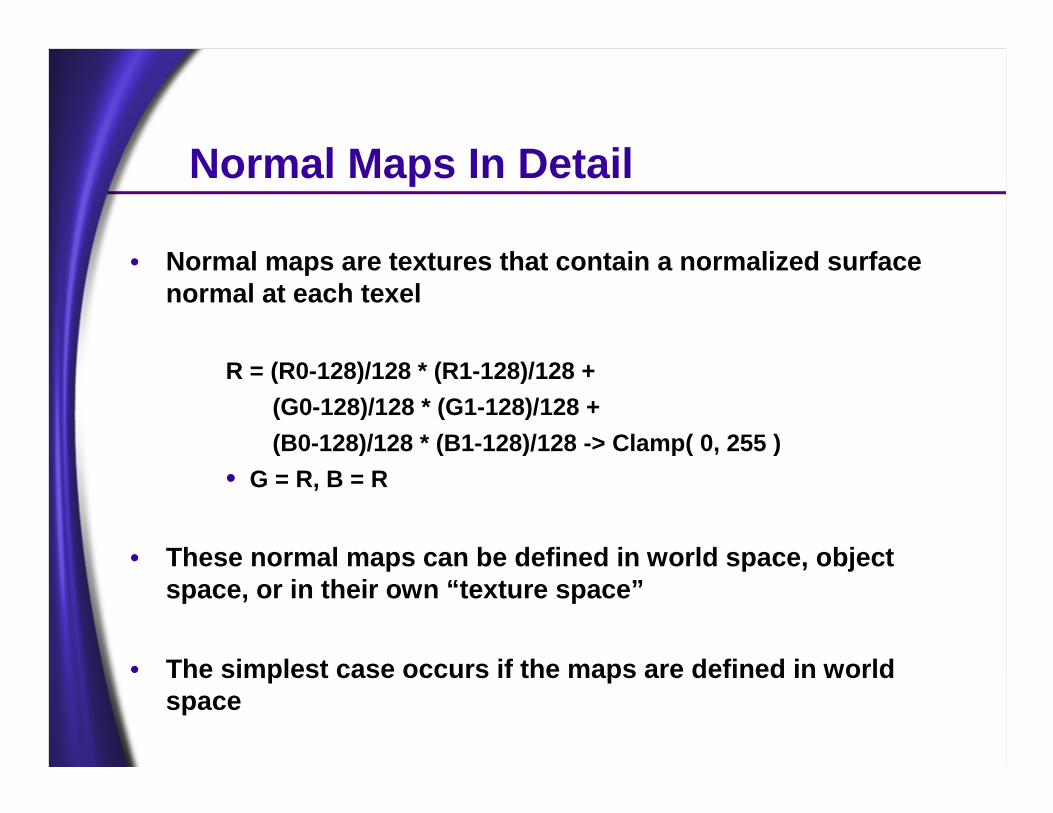
Normal Maps In Detail
• Normal maps are textures that contain a normalized surface normal at each texel
R = (R0-128)/128 * (R1-128)/128 + (G0-128)/128 * (G1-128)/128 + (B0-128)/128 * (B1-128)/128 -> Clamp( 0, 255 )
• G = R, B = R
• These normal maps can be defined in world space, object space, or in their own “texture space”
• The simplest case occurs if the maps are defined in world space
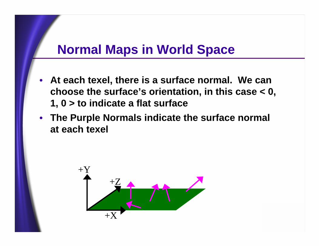
Normal Maps in World Space
• At each texel, there is a surface normal. We can choose the surface’s orientation, in this case < 0, 1, 0 > to indicate a flat surface
• The Purple Normals indicate the surface normal at each texel
+Y+Z
+X
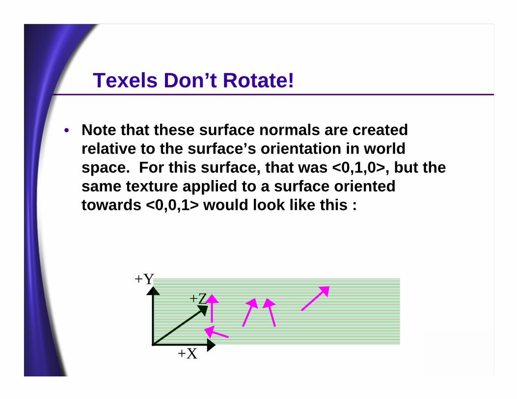
Texels Don’t Rotate!
• Note that these surface normals are created relative to the surface’s orientation in world space. For this surface, that was <0,1,0>, but the same texture applied to a surface oriented towards <0,0,1> would look like this :
+Y+Z
+X
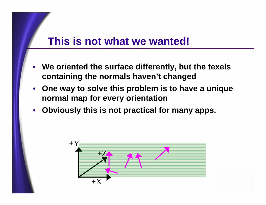
This is not what we wanted!
• We oriented the surface differently, but the texelscontaining the normals haven’t changed
• One way to solve this problem is to have a unique normal map for every orientation
• Obviously this is not practical for many apps.
+Z+Y
+X
How to Avoid Duplicating Normal Maps
• What is the problem?• The normals were defined in one space based on
how the textures were applied to the model or geometry
• The light is defined in world space• We can’t perform the L DOT N dot product between
vectors in two different spaces• We can generate the normal maps to always be
defined relative to world space• Or, we can move the light into “texture space”
Texture Space?
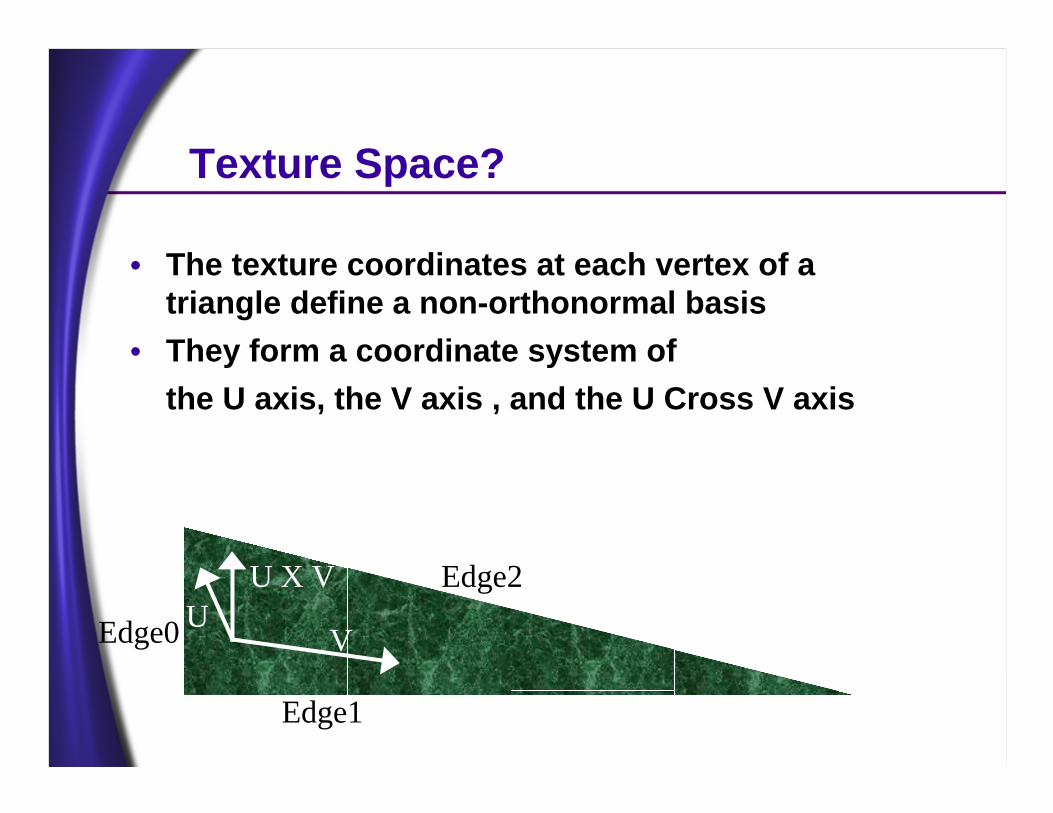
• The texture coordinates at each vertex of a triangle define a non-orthonormal basis
• They form a coordinate system ofthe U axis, the V axis , and the U Cross V axis
UU X V
VEdge0
Edge1
Edge2
How do we define Texture Space?
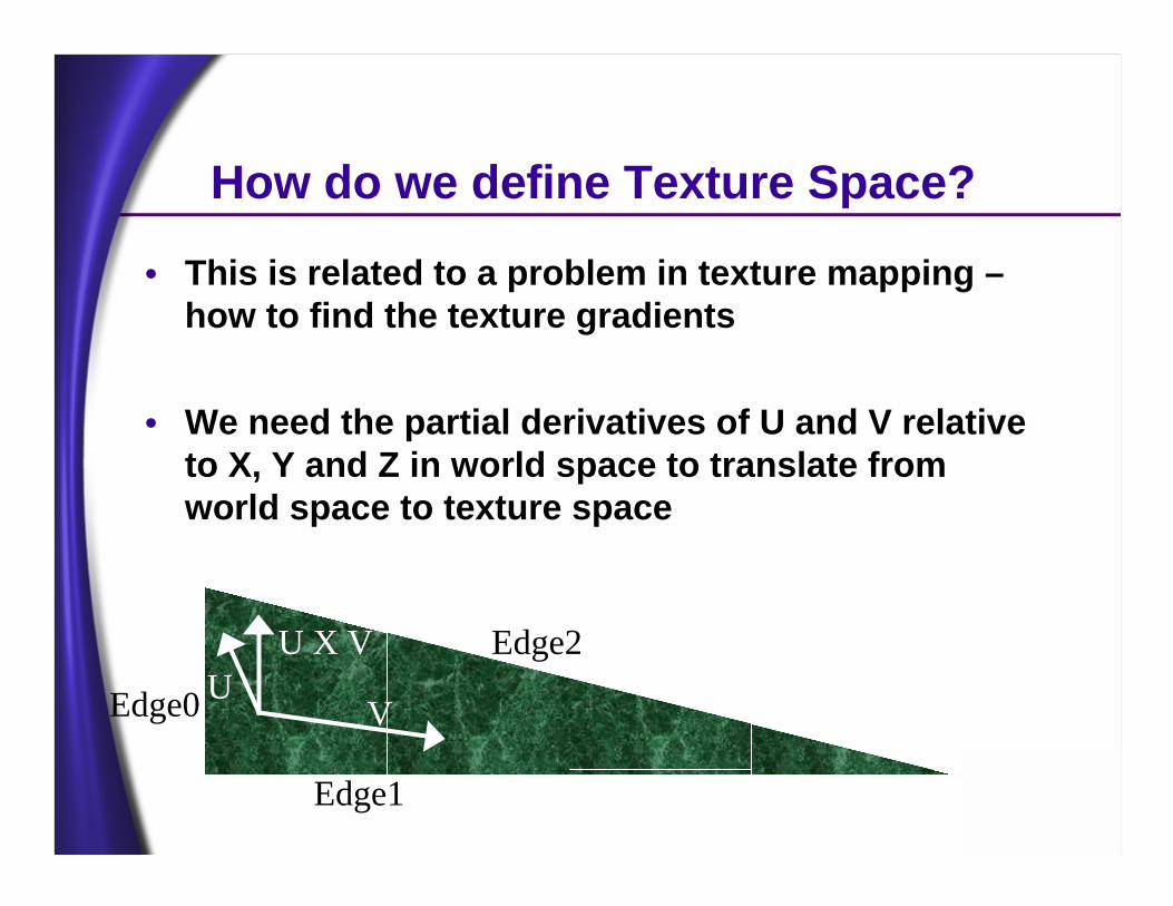
• This is related to a problem in texture mapping –how to find the texture gradients
• We need the partial derivatives of U and V relative to X, Y and Z in world space to translate from world space to texture space
UU X V
VEdge0
Edge1
Edge2
Defining Texture Space
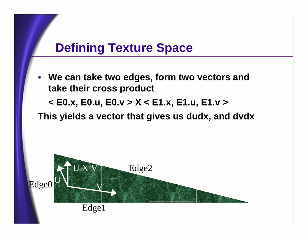
• We can take two edges, form two vectors and take their cross product< E0.x, E0.u, E0.v > X < E1.x, E1.u, E1.v >
This yields a vector that gives us dudx, and dvdx
UU X V
VEdge0
Edge1
Edge2
Generating the Partial Derivatives
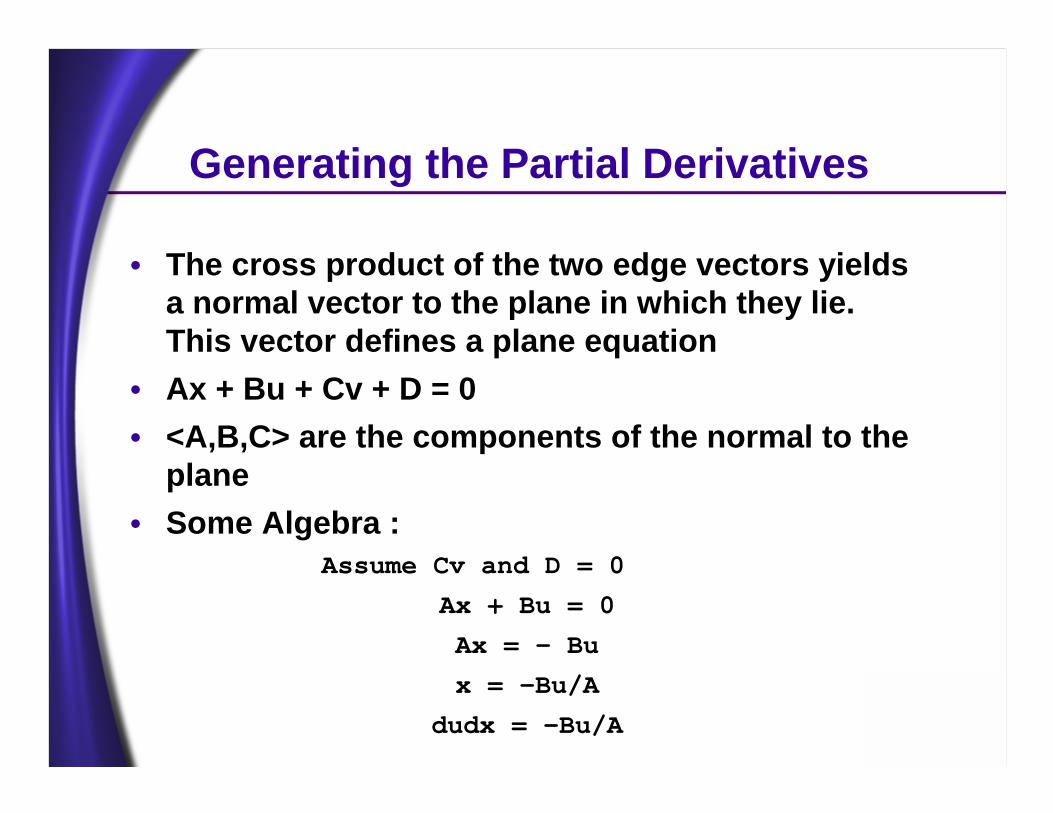
• The cross product of the two edge vectors yields a normal vector to the plane in which they lie. This vector defines a plane equation
• Ax + Bu + Cv + D = 0• <A,B,C> are the components of the normal to the
plane• Some Algebra :
Assume Cv and D = 0
Ax + Bu = 0
Ax = - Bu
x = -Bu/A
dudx = -Bu/A
Defining Texture Space
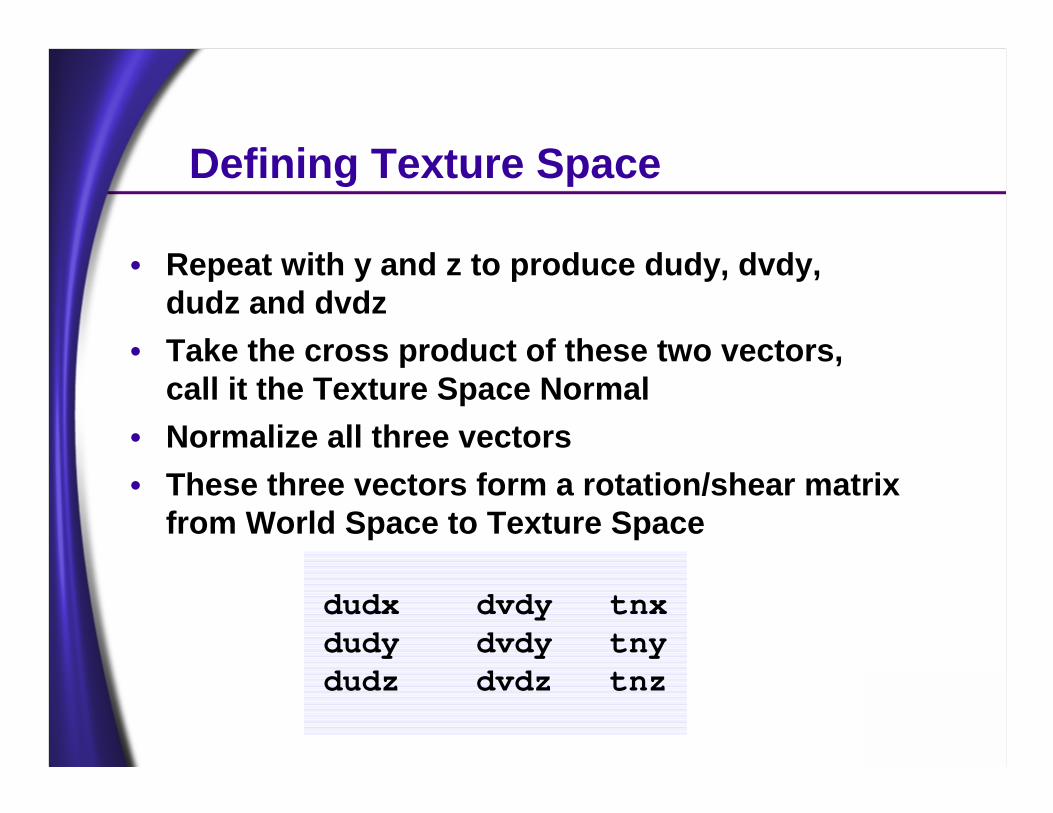
• Repeat with y and z to produce dudy, dvdy, dudz and dvdz
• Take the cross product of these two vectors, call it the Texture Space Normal
• Normalize all three vectors• These three vectors form a rotation/shear matrix
from World Space to Texture Space
dudx dvdy tnxdudy dvdy tnydudz dvdz tnz
What does this mean?
• We can generate this for each vertex of our geometry, giving us a way to move a light position or direction vector into texture space
• This is exactly what is needed for either Embossing or DOTPRODUCT3 bump mapping, as well as per-pixel lighting
• This ideally is done as a preprocessing step, and only recomputed if a model is morphed
Benefits of Texture Space• By defining this texture space, we can light or
emboss any vertex correctly
• For each vertex, we move the light vector or half vector into local texture space
• We can then store this vector in a 3D texture coordinate which indexes into a cube map or paraboloid map containing unit normals
• Alternately, we can normalize the vector on the CPU and store in the D3DTA_DIFFUSE or D3DTA_SPECULAR component
Height Maps To Normal Maps
• To take advantage of either Embossing, DOT3 bump mapping or per-pixel lighting, Artists should generate Height Maps
• A Height Map is a grayscale image, either stored in the RGB or Alpha channel• White indicates ‘High’• Black indicates ‘Low’• Gray values represent values inbetween
• For DOT3 techniques, including bump mapping and per-pixel lighting, this height map must be converted into a Normal Map
Converting Height Maps To Normal Maps
• Use 3 adjacent height samples to form a triangle in model space at each texel
• Turn this triangle’s normal into an RGB vector and store in a Normal Map Texture
• There is an arbitrary scale factor that determines the relative scale of the height dimension compared to the s & t texel dimensions
• Higher scale values create taller triangles, thus more horizontal normals
Normal Map Summary
• With “Texture Space” Normal maps :
• The artist applies a height map texture to a model in any arbitrary manner
• The height map texture is converted into a normal map in a preprocess step
• The local texture space matrix is defined for each vertex in a preprocess step
Texture Space
• If your geometry shares vertices via indexed primitives, you can simply compute a Texture Space matrix for each vertex based on one of the triangles attached to the vertex
• If you do not share vertices, you must average the texture spaces computed for each triangle to come up with an average Texture Space for each vertex• This is exactly analogous to generating Vertex Normals
from Face Normals for Lighting
Normal Map Summary• For each light in the scene
• Find surfaces facing the light• Rotate light direction into local texture space at
each vertex• If Embossing, generate U + dU, V + dV and store• If using Cube Maps, store Lx, Ly, Lz in S,T,R of
Normalization Cube Map texture• If using D3DTA_DIFFUSE to store light vectors,
normalize the light vector and store in D3DTA_DIFFUSE
What About Specular?
• So far I’ve only discussed diffuse lighting –specular is quite similar
• The first difference is to compute the Half Angle H per vertex instead of L and move it into local texture space• This is a bit more expensive
• The next difference is that you may want to perform specular bump mapping as a final pass
• To get high specular exponents for sharp highlights, simply set up the texture stages to perform current * current a few times and/or use SRCCOLOR*SRCCOLOR alpha blending
Directional Lights are Easy, What about Point Lights?
• Points lights are a little more involved
• The Normalized Vertex To Light vector L is computed per-vertex and stored in the D3DTA_DIFFUSE or D3DTA_SPECULAR of the vertex. It is interpolated linearly in this case
• Alternately, we can store the Unnormalized Vertex To Light Vector in texture coordinates to index a cubemap or paraboloid map. This achieves spherical interpolation of the vertex
• The distance attenuation requires a bit more work…
Point Light Attenuation
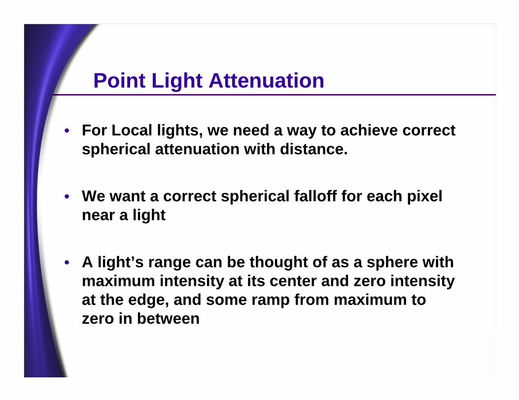
• For Local lights, we need a way to achieve correct spherical attenuation with distance.
• We want a correct spherical falloff for each pixel near a light
• A light’s range can be thought of as a sphere with maximum intensity at its center and zero intensity at the edge, and some ramp from maximum to zero in between
Point Light Attenuation
• Can we compute this per-vertex? And store as a color ala Gouraud shading?
• Let’s give it a shot…
Point Light Attenuation
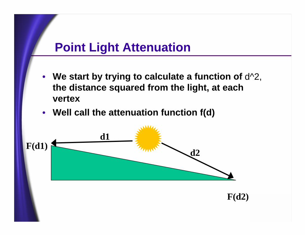
• We start by trying to calculate a function of d^2, the distance squared from the light, at each vertex
• Well call the attenuation function f(d)
d1
d2
F(d2)
F(d1)
Point Light Attenuation
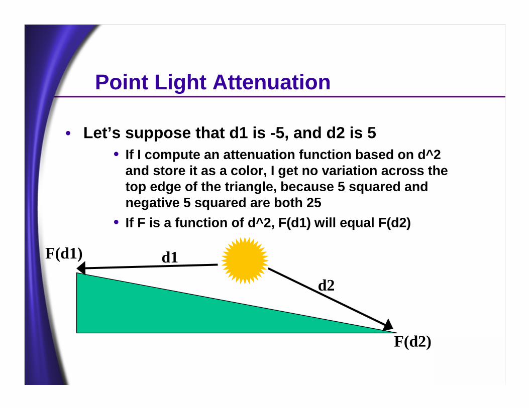
• Let’s suppose that d1 is -5, and d2 is 5• If I compute an attenuation function based on d^2
and store it as a color, I get no variation across the top edge of the triangle, because 5 squared and negative 5 squared are both 25
• If F is a function of d^2, F(d1) will equal F(d2)
d1
d2
F(d2)
F(d1)
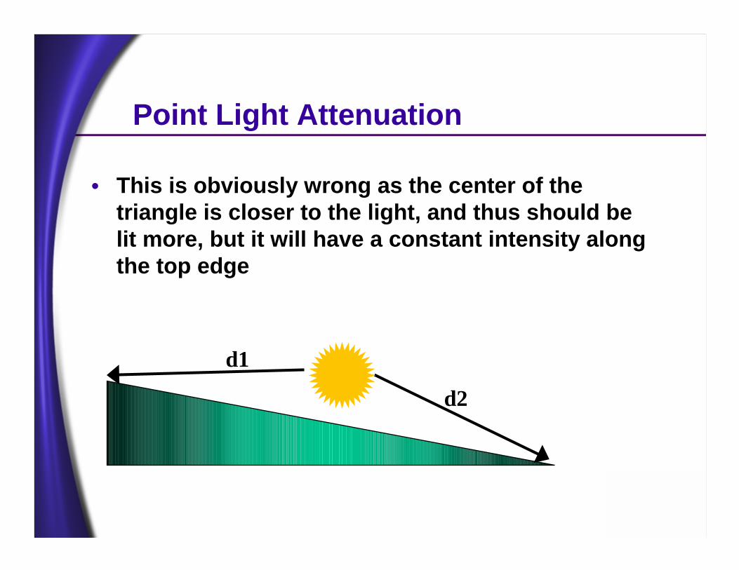
Point Light Attenuation
• This is obviously wrong as the center of the triangle is closer to the light, and thus should be lit more, but it will have a constant intensity along the top edge
d1
d2
Point Light Attenuation
• This is not just a sampling problem, tessellating more won’t fix the issue, it will just make it less apparent. This is one of the limitations of vertex lighting.
• However, if are triangles are small with respect to the light range, vertex lighting is exactly what we should use, especially on HW
• But, not everything is highly tessellated, such as floors, walls and large objects
• A per-pixel solution would complement vertex lighting nicely
Interpolation Problems
• We can’t interpolate attenuation per-vertex, because it attenuation is a spherical function, not linear
• We can’t interpolate f(d), or even d because colors in general only store positive values
• We need to interpolate the <x,y,z> position itself –which can and will vary from negative through positive values - and perform f(d) per pixel instead
Point Light Attenuation
• So, what do we have that can interpolate x,y & z as signed values properly?• Texture coordinates
• What if we took the distance to the light in separate components x,y,& z and computed attenuation via the texture combiners?
• This is equivalent to moving the vertex into ‘light space’ and simply using the texture coordinates to interpolate the resultant position
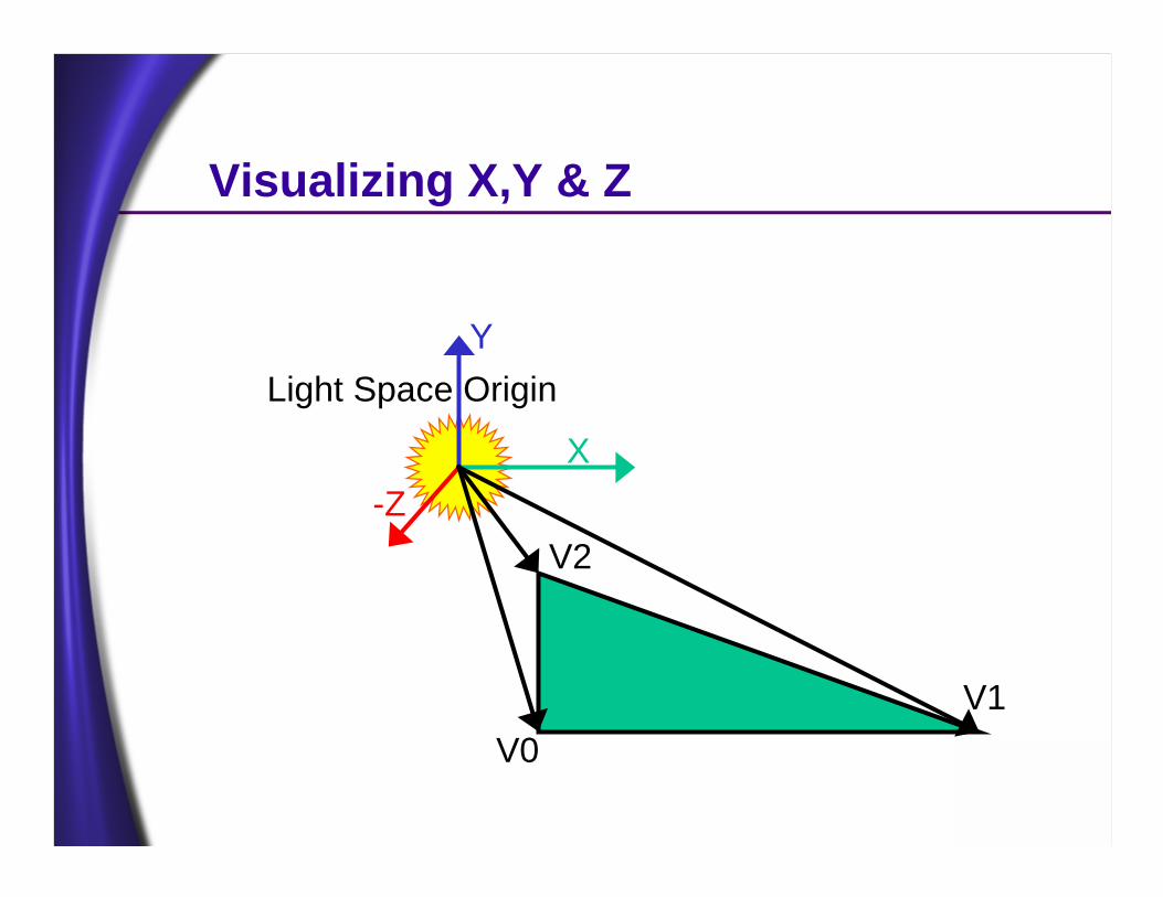
Visualizing X,Y & Z
Light Space OriginY
X-Z
V0V1
V2
Point Light Attenuation
• Well, 3D textures would be a nice solution• Just make a 3D texture containing the attenuation
function, and use x,y and z to index into the texture via 3D texture coordinates
• Scale x,y and z by 1/ light range• Use Clamp texture addressing• Make sure outer border of texture is black• Make inside of texture a smooth blend from white
to black• Attenuation Factor = 1 / ( c0 + c1*d + c2*d*d )
Point Light Attenuation
• This works great…at least I think it will, I don’t have a 3D texture-capable video card yet…• We’ll have to find another way
• We don’t have 3D textures, but maybe we can use one or more 2D textures to get the same function
• First of all, we can’t use the same attenuation function Att = 1 / ( c0 + c1*d + c2*d*d )
• There is no way to perform a reciprocal in a D3D texture blend mode, given x,y and z
Point Light Attenuation• We can’t use the standard attenuation used for
vertex lighting• Att = 1 / ( c0 + c1*d + c2*d*d )• Partially because it can’t handle denominator
values less than one, and all we have are color values from [0..1]
• Let’s turn that into an advantage• We need a function that goes from 1 at distance
zero to 0 at distance 1 ( which represents the light’s range )
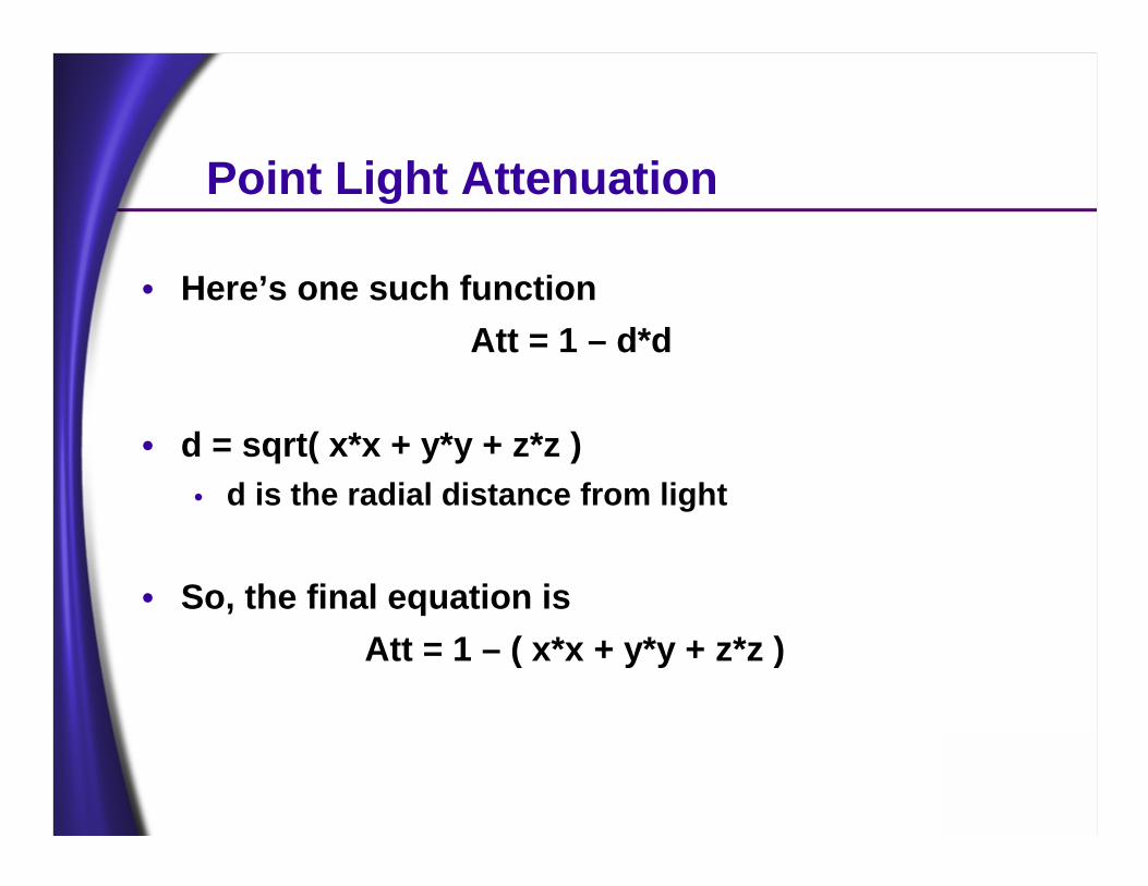
Point Light Attenuation
• Here’s one such functionAtt = 1 – d*d
• d = sqrt( x*x + y*y + z*z )• d is the radial distance from light
• So, the final equation isAtt = 1 – ( x*x + y*y + z*z )
Point Light Attenuation
• This requires two textures, in either one or two passes, depending on whether the card has multi-texture
• For the purposes of this talk, we will assume 2-stage multi-texture
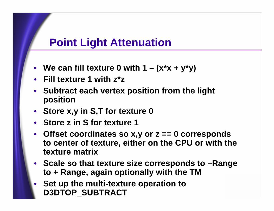
Point Light Attenuation
• We can fill texture 0 with 1 – (x*x + y*y)• Fill texture 1 with z*z• Subtract each vertex position from the light
position• Store x,y in S,T for texture 0• Store z in S for texture 1• Offset coordinates so x,y or z == 0 corresponds
to center of texture, either on the CPU or with the texture matrix
• Scale so that texture size corresponds to –Range to + Range, again optionally with the TM
• Set up the multi-texture operation to D3DTOP_SUBTRACT

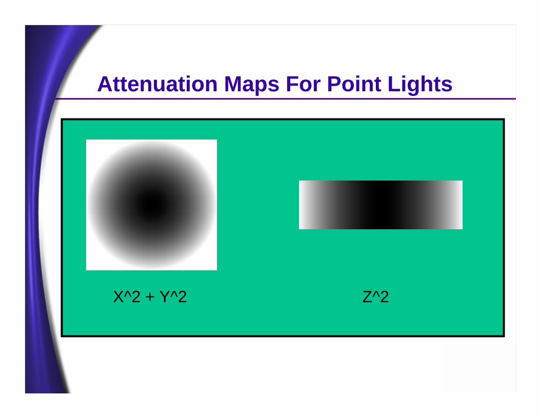
Attenuation Maps For Point Lights
X^2 + Y^2 Z^2
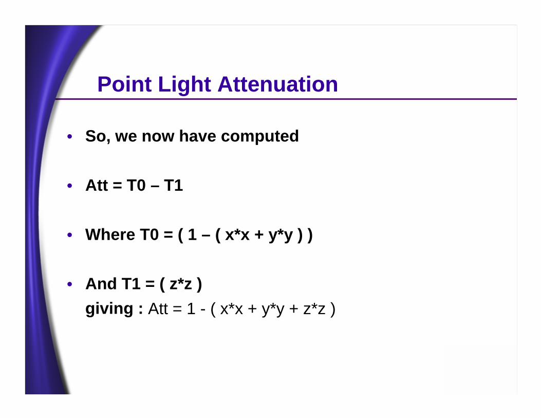
Point Light Attenuation
• So, we now have computed
• Att = T0 – T1
• Where T0 = ( 1 – ( x*x + y*y ) )
• And T1 = ( z*z )giving : Att = 1 - ( x*x + y*y + z*z )
Attenuation Maps For Point Lights
X^2 + Y^2 Z^2
Alternate Distance Squared Computation
• Not all cards have RGB or Alpha subtraction capability.
• An alternative is to store X*X + Y*Y in T0 and Z*Z in T1
• Then simply add T0 and T1
• Use SRCCOLOR * INVSRCCOLOR, ZERO Or SRCCOLOR * INVSRCALPHA, ZERO blending
Point Light Attenuation• The steps for Diffuse Local Lights are :
• Pass 0: Render Ambient Lighting ( Including diffuse lightmaps ) & Depth
• Pass 1: Render the Local Light Attenuation Functions Additively
• Only objects partially in the light’s sphere
• Pass 2: Add or Modulate in the Diffuse Material Texture ( Base Texture )
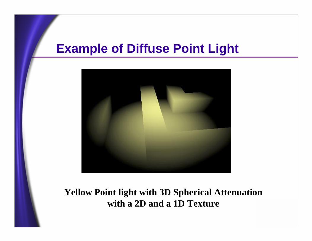
Example of Diffuse Point Light
Yellow Point light with 3D Spherical Attenuation with a 2D and a 1D Texture
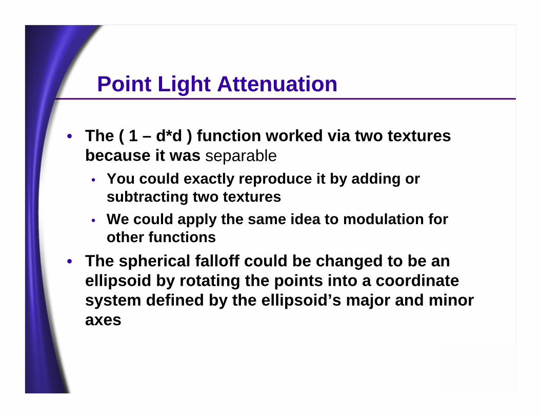
• The ( 1 – d*d ) function worked via two textures because it was separable• You could exactly reproduce it by adding or
subtracting two textures• We could apply the same idea to modulation for
other functions• The spherical falloff could be changed to be an
ellipsoid by rotating the points into a coordinate system defined by the ellipsoid’s major and minor axes
Point Light Attenuation
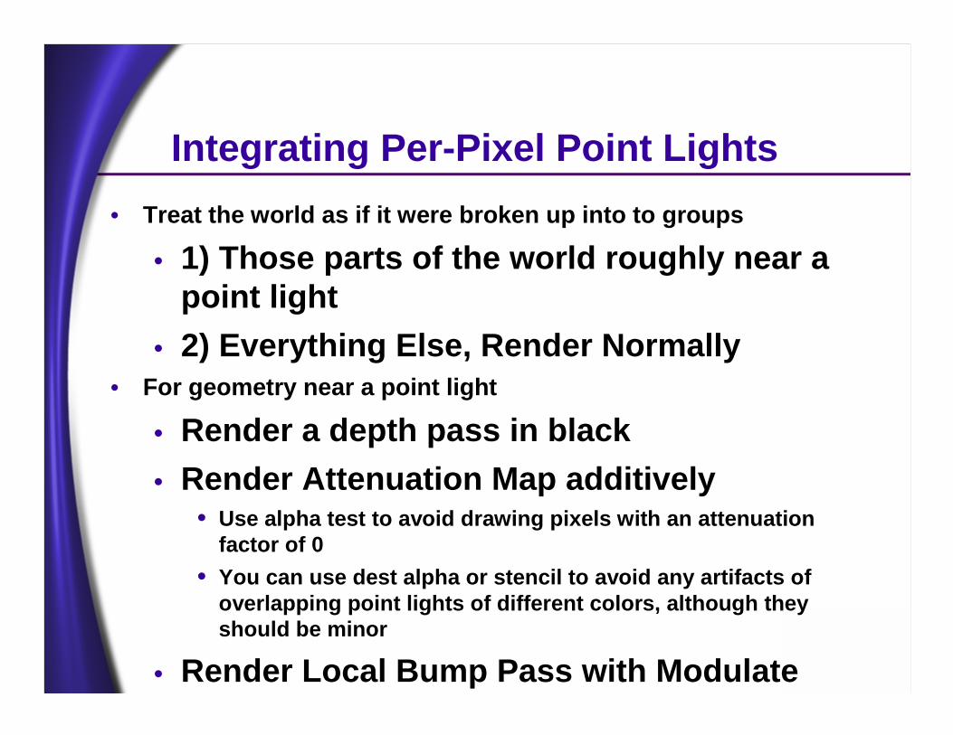
Integrating Per-Pixel Point Lights• Treat the world as if it were broken up into to groups
• 1) Those parts of the world roughly near a point light
• 2) Everything Else, Render Normally• For geometry near a point light
• Render a depth pass in black• Render Attenuation Map additively
• Use alpha test to avoid drawing pixels with an attenuation factor of 0
• You can use dest alpha or stencil to avoid any artifacts of overlapping point lights of different colors, although they should be minor
• Render Local Bump Pass with Modulate
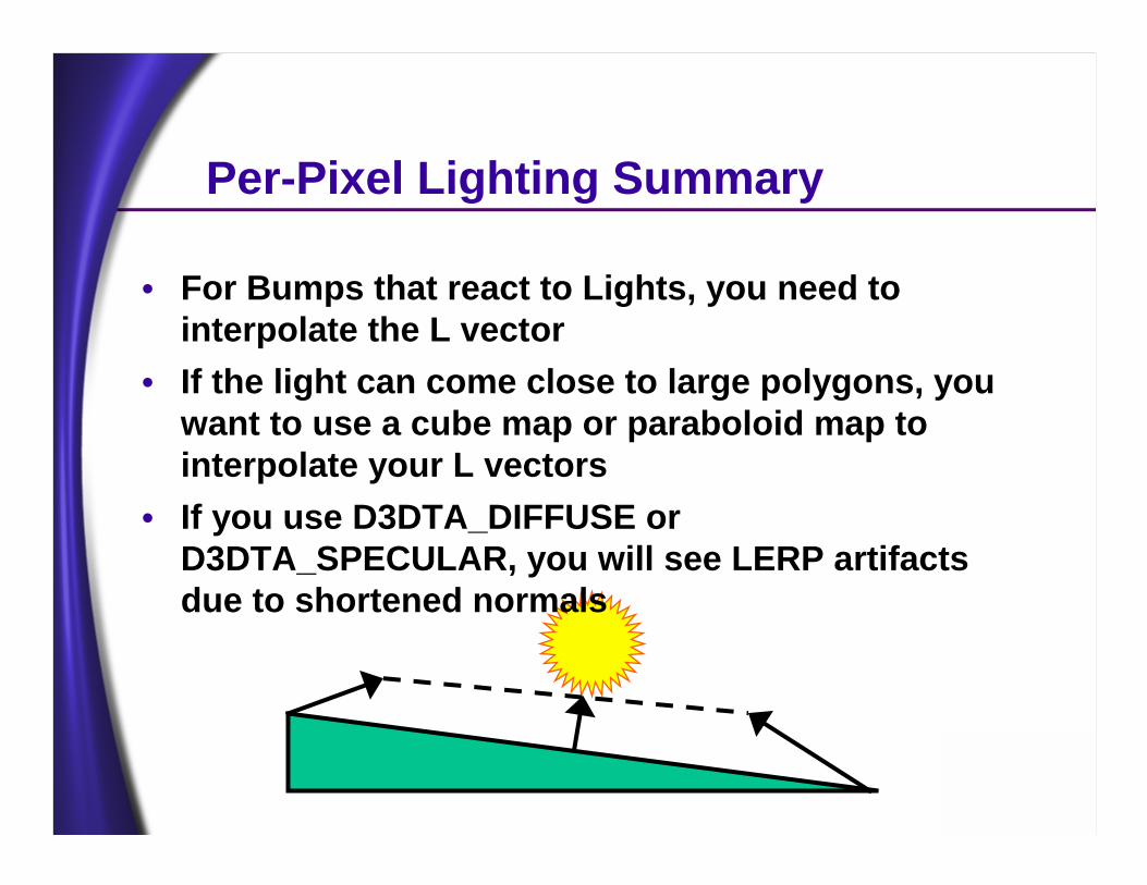
Per-Pixel Lighting Summary
• For Bumps that react to Lights, you need to interpolate the L vector
• If the light can come close to large polygons, you want to use a cube map or paraboloid map to interpolate your L vectors
• If you use D3DTA_DIFFUSE or D3DTA_SPECULAR, you will see LERP artifacts due to shortened normals
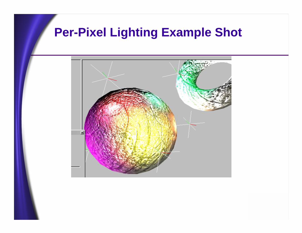
Per-Pixel Lighting Example Shot
Summary• To achieve the goal of maximum per-pixel
complexity in a dynamic environment, we want to perform lighting per-pixel
• We can use the D3DTOP_DOTPRODUCT3 operation to calculate per-pixel lighting
• Normal Maps are Textures used to store surface normals
• To achieve per-pixel lighting on an arbitrarily texture mapped object, Texture Space Matrices must be generated and stored per vertex
• 3D Spherical Point-Light Attenuation can be computed with a 2D Texture and a 1D Texture!
• Height maps are easy for artists to create• White is high • Black is low
• Also can be generated automatically using luminance or a grayscale of an RGB texture
• Height maps can be used now for Bump Mapping, Per-Pixel Lighting, Elevation Maps and Embossing
• In the future, height maps will be used for displacement maps
• Don’t pre-light your textures, Per-pixel light them instead!
Call To Action: Create Height Maps


![Catolog of LED Displayags-electronics.com/web-storage/webstorage4/LED... · 5 6. LED Lighting Series Ⅰ. Background Lighting Specifications: [“PH” refers to Pixel Pitch (mm)]](https://img.pdfslide.us/doc/110x75/5f90ad1ef140ed28f82a10e3/catolog-of-led-displayags-5-6-led-lighting-series-a-background-lighting-specifications.jpg)