Embed Size (px)
Citation preview

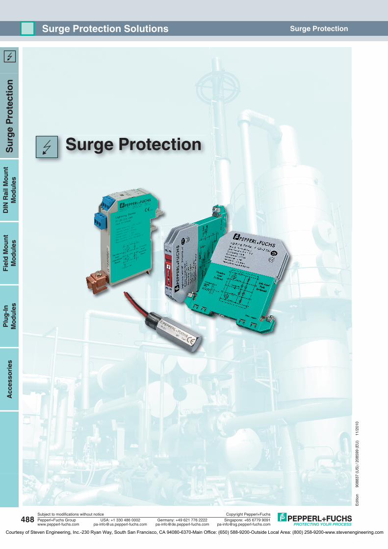
Surge Protection Solutions
486Subject to modifications without notice
Pepperl+Fuchs Groupwww.pepperl-fuchs.com
USA: +1 330 486 [email protected] [email protected]
Singapore: +65 6779 [email protected]
Copyright Pepperl+Fuchs
Germany: +49 621 776 2222
Editio
n 90
8837
(US)
/ 20
8599
(EU)
11
/201
0
Courtesy of Steven Engineering, Inc.-230 Ryan Way, South San Francisco, CA 94080-6370-Main Office: (650) 588-9200-Outside Local Area: (800) 258-9200-www.stevenengineering.com
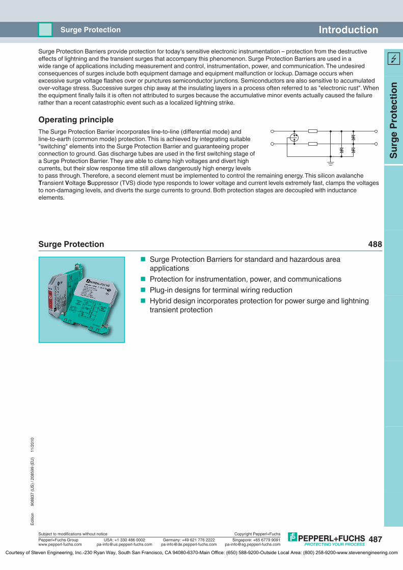
Surge Protection Barriers provide protection for today's sensitive electronic instrumentation – protection from the destructive eff ects of lightning and the transient surges that accompany this phenomenon. Surge Protection Barriers are used in a wide range of applications including measurement and control, instrumentation, power, and communication. The undesired consequences of surges include both equipment damage and equipment malfunction or lockup. Damage occurs when excessive surge voltage fl ashes over or punctures semiconductor junctions. Semiconductors are also sensitive to accumulated over-voltage stress. Successive surges chip away at the insulating layers in a process often referred to as "electronic rust". When the equipment fi nally fails it is often not attributed to surges because the accumulative minor events actually caused the failure rather than a recent catastrophic event such as a localized lightning strike.
Operating principleThe Surge Protection Barrier incorporates line-to-line (diff erential mode) and line-to-earth (common mode) protection. This is achieved by integrating suitable "switching" elements into the Surge Protection Barrier and guaranteeing proper connection to ground. Gas discharge tubes are used in the fi rst switching stage of a Surge Protection Barrier. They are able to clamp high voltages and divert high currents, but their slow response time still allows dangerously high energy levels to pass through. Therefore, a second element must be implemented to control the remaining energy. This silicon avalanche Transient Voltage Suppressor (TVS) diode type responds to lower voltage and current levels extremely fast, clamps the voltages to non-damaging levels, and diverts the surge currents to ground. Both protection stages are decoupled with inductance elements.
Surge Protection 488
Surge Protection Barriers for standard and hazardous area applications Protection for instrumentation, power, and communications Plug-in designs for terminal wiring reduction Hybrid design incorporates protection for power surge and lightning
transient protection
487
IntroductionSurge Protection
Subject to modifications without notice
Pepperl+Fuchs Groupwww.pepperl-fuchs.com
USA: +1 330 486 [email protected] [email protected]
Singapore: +65 6779 [email protected]
Copyright Pepperl+Fuchs
Germany: +49 621 776 2222
Su
rge
Pro
tect
ion
Editio
n 90
8837
(US)
/ 20
8599
(EU)
11
/201
0
Courtesy of Steven Engineering, Inc.-230 Ryan Way, South San Francisco, CA 94080-6370-Main Office: (650) 588-9200-Outside Local Area: (800) 258-9200-www.stevenengineering.com
Surge Protection
488
Surge ProtectionSurge Protection Solutions
Su
rge
Pro
tect
ion
Plu
g-I
nM
od
ule
sA
cces
sori
esD
IN R
ail M
ou
nt
Mo
du
les
Fie
ld M
ou
nt
Mo
du
les
Subject to modifications without notice
Pepperl+Fuchs Groupwww.pepperl-fuchs.com
USA: +1 330 486 [email protected] [email protected]
Singapore: +65 6779 [email protected]
Copyright Pepperl+Fuchs
Germany: +49 621 776 2222
Editio
n 90
8837
(US)
/ 20
8599
(EU)
11
/201
0
Courtesy of Steven Engineering, Inc.-230 Ryan Way, South San Francisco, CA 94080-6370-Main Office: (650) 588-9200-Outside Local Area: (800) 258-9200-www.stevenengineering.com

Edi
tion
9088
37 (
US
) / 2
0859
9 (E
U)
11/2
010
489
Su
rge
Pro
tect
ion
Plu
g-I
nM
od
ule
sA
cces
sori
esD
IN R
ail M
ou
nt
Mo
du
les
Fie
ld M
ou
nt
Mo
du
les
Subject to modifications without notice
Pepperl+Fuchs Groupwww.pepperl-fuchs.com
USA: +1 330 486 [email protected] [email protected]
Singapore: +65 6779 [email protected]
Copyright Pepperl+Fuchs
Germany: +49 621 776 2222
Table of ContentsSurge Protection
System Description . . . . . . . . . . . . . . . . . . . . . . . . . . . . . . . . . . . . . . . . . . . . 490
DIN Rail Mount Modules
Selection Tables. . . . . . . . . . . . . . . . . . . . . . . . . . . . . . . . . . . . . . . . . . . . . . . . . . . . . . . . 499
Product Data Sheets . . . . . . . . . . . . . . . . . . . . . . . . . . . . . . . . . . . . . . . . . . . . . . . . . . . . 501
Entity Parameters. . . . . . . . . . . . . . . . . . . . . . . . . . . . . . . . . . . . . . . . . . . . . . . . . . . . . . . 522
Field Mount Modules
Selection Tables. . . . . . . . . . . . . . . . . . . . . . . . . . . . . . . . . . . . . . . . . . . . . . . . . . . . . . . . 499
Product Data Sheets . . . . . . . . . . . . . . . . . . . . . . . . . . . . . . . . . . . . . . . . . . . . . . . . . . . . 509
Entity Parameters. . . . . . . . . . . . . . . . . . . . . . . . . . . . . . . . . . . . . . . . . . . . . . . . . . . . . . . 522
Plug-In Modules
Selection Tables. . . . . . . . . . . . . . . . . . . . . . . . . . . . . . . . . . . . . . . . . . . . . . . . . . . . . . . . 500
Product Data Sheets . . . . . . . . . . . . . . . . . . . . . . . . . . . . . . . . . . . . . . . . . . . . . . . . . . . . 512
Entity Parameters. . . . . . . . . . . . . . . . . . . . . . . . . . . . . . . . . . . . . . . . . . . . . . . . . . . . . . . 522
Accessories
Selection Tables. . . . . . . . . . . . . . . . . . . . . . . . . . . . . . . . . . . . . . . . . . . . . . . . . . . . . . . . 500
Product Data Sheets . . . . . . . . . . . . . . . . . . . . . . . . . . . . . . . . . . . . . . . . . . . . . . . . . . . . 523
Courtesy of Steven Engineering, Inc.-230 Ryan Way, South San Francisco, CA 94080-6370-Main Office: (650) 588-9200-Outside Local Area: (800) 258-9200-www.stevenengineering.com
490
Edi
tion
9088
37 (
US
) / 2
0859
9 (E
U)
11/2
010
Su
rge
Pro
tect
ion
Plu
g-I
nM
od
ule
sA
cces
sori
esD
IN R
ail M
ou
nt
Mo
du
les
Fie
ld M
ou
nt
Mo
du
les
Subject to modifications without notice
Pepperl+Fuchs Groupwww.pepperl-fuchs.com
USA: +1 330 486 [email protected] [email protected]
Singapore: +65 6779 [email protected]
Copyright Pepperl+Fuchs
Germany: +49 621 776 2222
System Description Surge Protection
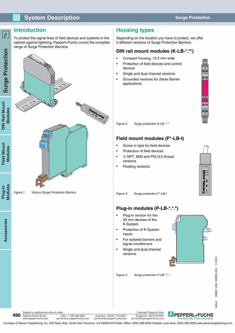
IntroductionTo protect the signal lines of field devices and systems in the cabinet against lightning. Pepperl+Fuchs covers the complete range of Surge Protection Barriers.
Figure 1 Various Surge Protection Barriers
Housing typesDepending on the location you have to protect, we offer 3 different versions of Surge Protection Barriers.
DIN rail mount modules (K-LB-*.**)• Compact housing, 12.5 mm wide
• Protection of field devices and control devices
• Single and dual channel versions
• Grounded versions for Zener Barrier applications
Figure 2 Surge protection K-LB-*.**
Field mount modules (F*-LB-I)• Screw in type for field devices
• Protection of field devices
• ½ NPT, M20 and PG13.5 thread versions
• Floating versions
Figure 3 Surge protection F*-LB-I
Plug-in modules (P-LB-*.*.*)• Plug-in version for the
20 mm devices of the K-System
• Protection of K-System inputs
• For isolated barriers and signal conditioners
• Single and dual channel versions
Figure 4 Surge protection P-LB-*.*.*
FS-LB-I
5 67 8
1 23 4
M20x15
FS-L
B-I
Courtesy of Steven Engineering, Inc.-230 Ryan Way, South San Francisco, CA 94080-6370-Main Office: (650) 588-9200-Outside Local Area: (800) 258-9200-www.stevenengineering.com
Edi
tion
9088
37 (
US
) / 2
0859
9 (E
U)
11/2
010
491
Su
rge
Pro
tect
ion
Plu
g-I
nM
od
ule
sA
cces
sori
esD
IN R
ail M
ou
nt
Mo
du
les
Fie
ld M
ou
nt
Mo
du
les
Subject to modifications without notice
Pepperl+Fuchs Groupwww.pepperl-fuchs.com
USA: +1 330 486 [email protected] [email protected]
Singapore: +65 6779 [email protected]
Copyright Pepperl+Fuchs
Germany: +49 621 776 2222
System DescriptionSurge Protection
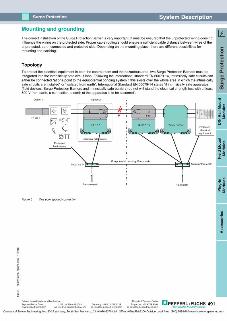
Mounting and grounding
The correct installation of the Surge Protection Barrier is very important. It must be ensured that the unprotected wiring does not influence the wiring on the protected side. Proper cable routing should ensure a sufficient cable distance between wires of the unprotected, earth connected and protected side. Depending on the mounting place, there are different possibilities for mounting and earthing.
TopologyTo protect the electrical equipment in both the control room and the hazardous area, two Surge Protection Barriers must be integrated into the intrinsically safe circuit loop. Following the international standard EN 60079-14, intrinsically safe circuits can either be connected "at one point to the equipotential bonding system if this exists over the whole area in which the intrinsically safe circuits are installed" or "isolated from earth". International Standard EN 60079-14 states "if intrinsically safe apparatus (field devices, Surge Protection Barriers and intrinsically safe barriers) do not withstand the electrical strength test with at least 500 V from earth, a connection to earth at the apparatus is to be assumed".
Figure 5 One point ground connection
+
-
IP
Additional field housing
Equipotential bonding (if required)
Option 1 Option 2
Protectedelectrical
equipment
Protectedfield device
Local earth
Remote earth Plant earth
Main system earth
K-LB-*.*
F*-LB-I
K-LB-*.*G Zener Barrier
Courtesy of Steven Engineering, Inc.-230 Ryan Way, South San Francisco, CA 94080-6370-Main Office: (650) 588-9200-Outside Local Area: (800) 258-9200-www.stevenengineering.com
492
Edi
tion
9088
37 (
US
) / 2
0859
9 (E
U)
11/2
010
Su
rge
Pro
tect
ion
Plu
g-I
nM
od
ule
sA
cces
sori
esD
IN R
ail M
ou
nt
Mo
du
les
Fie
ld M
ou
nt
Mo
du
les
Subject to modifications without notice
Pepperl+Fuchs Groupwww.pepperl-fuchs.com
USA: +1 330 486 [email protected] [email protected]
Singapore: +65 6779 [email protected]
Copyright Pepperl+Fuchs
Germany: +49 621 776 2222
System Description Surge Protection
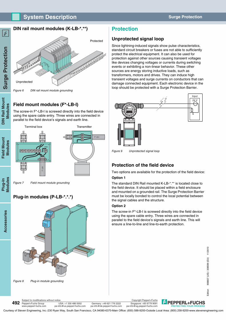
DIN rail mount modules (K-LB-*.**)
Figure 6 DIN rail mount module grounding
Field mount modules (F*-LB-I)The screw-in F*-LB-I is screwed directly into the field device using the spare cable entry. Three wires are connected in parallel to the field device’s signals and earth line.
Figure 7 Field mount module grounding
Plug-in modules (P-LB-*.*.*)
Figure 8 Plug-in module grounding
Protection
Unprotected signal loopSince lightning-induced signals show pulse characteristics, standard circuit breakers or fuses are not able to sufficiently protect the electrical equipment. It can also be used for protection against other sources causing transient voltages like devices changing voltages or currents during switching events or exhibiting a non-linear behavior. These other sources are energy storing inductive loads, such as transformers, motors and drives. They can induce high transient voltages and surge currents on conductors that can damage connected equipment. Each electronic device in the loop should be protected with a Surge Protection Barrier.
Figure 9 Unprotected signal loop
Protection of the field deviceTwo options are available for the protection of the field device:
Option 1
The standard DIN Rail mounted K-LB-*.** is located close to the field device. It should be placed within a field enclosure and mounted on a grounded rail. The Surge Protection Barrier must be locally bonded to control the local potential between the signal cables and the structure.
Option 2
The screw-in F*-LB-I is screwed directly into the field device using the spare cable entry. Three wires are connected in parallel to the field device’s signals and earth line. This will ensure a line-to-line and line-to-earth protection.
Protected
Unprotected
TransmitterTerminal box
GND
F*-LB-I
F*-
LB-I
24 V
Input
Courtesy of Steven Engineering, Inc.-230 Ryan Way, South San Francisco, CA 94080-6370-Main Office: (650) 588-9200-Outside Local Area: (800) 258-9200-www.stevenengineering.com
Edi
tion
9088
37 (
US
) / 2
0859
9 (E
U)
11/2
010
493
Su
rge
Pro
tect
ion
Plu
g-I
nM
od
ule
sA
cces
sori
esD
IN R
ail M
ou
nt
Mo
du
les
Fie
ld M
ou
nt
Mo
du
les
Subject to modifications without notice
Pepperl+Fuchs Groupwww.pepperl-fuchs.com
USA: +1 330 486 [email protected] [email protected]
Singapore: +65 6779 [email protected]
Copyright Pepperl+Fuchs
Germany: +49 621 776 2222
System DescriptionSurge Protection
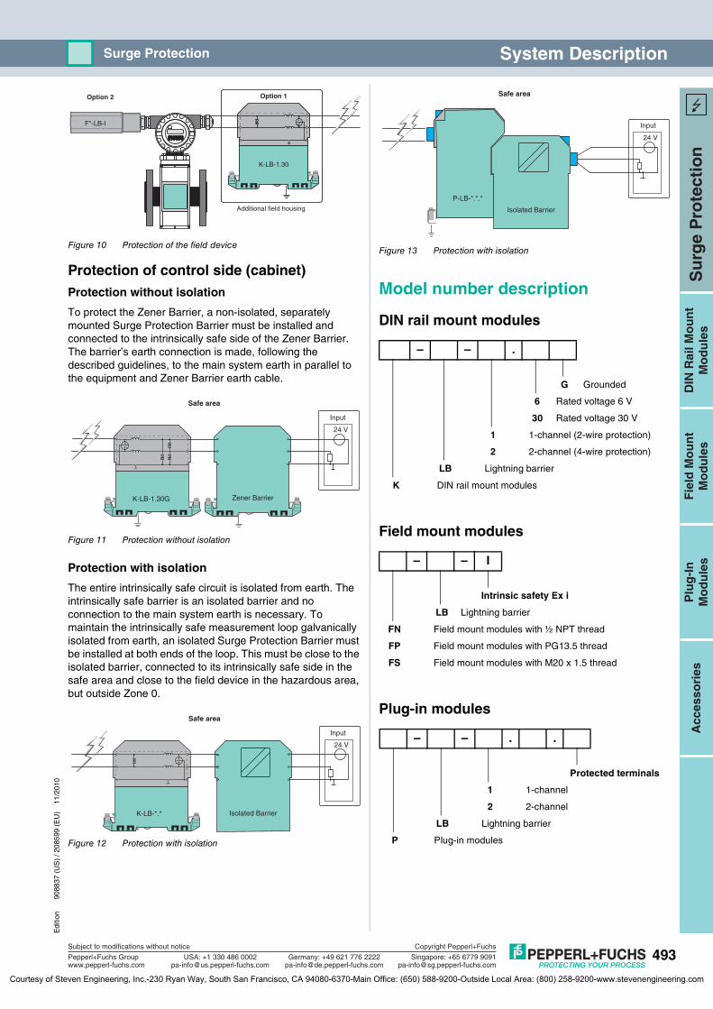
Figure 10 Protection of the field device
Protection of control side (cabinet)Protection without isolation
To protect the Zener Barrier, a non-isolated, separately mounted Surge Protection Barrier must be installed and connected to the intrinsically safe side of the Zener Barrier. The barrier’s earth connection is made, following the described guidelines, to the main system earth in parallel to the equipment and Zener Barrier earth cable.
Figure 11 Protection without isolation
Protection with isolation
The entire intrinsically safe circuit is isolated from earth. The intrinsically safe barrier is an isolated barrier and no connection to the main system earth is necessary. To maintain the intrinsically safe measurement loop galvanically isolated from earth, an isolated Surge Protection Barrier must be installed at both ends of the loop. This must be close to the isolated barrier, connected to its intrinsically safe side in the safe area and close to the field device in the hazardous area, but outside Zone 0.
Figure 12 Protection with isolation
Figure 13 Protection with isolation
Model number description
DIN rail mount modules
Field mount modules
Plug-in modules
K-LB-1.30
Additional field housing
Option 1Option 2
F*-LB-I
24 V
K-LB-1.30G
Input
Safe area
Zener Barrier
K-LB-*.*
24 V
Input
Safe area
Isolated Barrier
– – .
G Grounded
6 Rated voltage 6 V
30 Rated voltage 30 V
1 1-channel (2-wire protection)
2 2-channel (4-wire protection)
LB Lightning barrier
K DIN rail mount modules
– – I
Intrinsic safety Ex i
LB Lightning barrier
FN Field mount modules with ½ NPT thread
FP Field mount modules with PG13.5 thread
FS Field mount modules with M20 x 1.5 thread
– – . .
Protected terminals
1 1-channel
2 2-channel
LB Lightning barrier
P Plug-in modules
P-LB-*.*.*
24 V
Input
Safe area
Isolated Barrier
Courtesy of Steven Engineering, Inc.-230 Ryan Way, South San Francisco, CA 94080-6370-Main Office: (650) 588-9200-Outside Local Area: (800) 258-9200-www.stevenengineering.com

494
Edi
tion
9088
37 (
US
) / 2
0859
9 (E
U)
11/2
010
Su
rge
Pro
tect
ion
Plu
g-I
nM
od
ule
sA
cces
sori
esD
IN R
ail M
ou
nt
Mo
du
les
Fie
ld M
ou
nt
Mo
du
les
Subject to modifications without notice
Pepperl+Fuchs Groupwww.pepperl-fuchs.com
USA: +1 330 486 [email protected] [email protected]
Singapore: +65 6779 [email protected]
Copyright Pepperl+Fuchs
Germany: +49 621 776 2222
System Description Surge Protection
Safety Information for K-LB-*.** DIN rail mount modules
The corresponding data sheets, the Declaration of Conformity, the EC-Type Examination Certificate and applicable certificates (see data sheet) are an integral part of this document.
Intended useLaws and regulations applicable to the usage or planned purpose of usage must be observed. Devices are only approved for proper usage in accordance with intended use. Improper handling will result in voiding of any warrantee or manufacturer's responsibility.
Surge Protection Barriers are used as modules positioned upstream in the circuit from the corresponding electrical equipment. They make it possible to protect against overvoltages originating from various causes (lightning strikes, switching processes, etc.). This is achieved by diverting the transient current and limiting the voltage throughout the duration of the overvoltage surge. Various modules are available for protecting 2 or 4 conductors.
Protection of operating personnel and the system is not ensured if the product is not used in accordance with its intended use.
Intrinsic safety circuits that were operated with circuits of other types of protection may not be used as intrinsically safe circuits afterwards.
ApplicationSurge Protection Barriers themselves can be installed within the hazardous area of Zone 1. They can be used for intrinsically safe circuits up to Ex ia IIC. The ignition protection class is determined by the connected intrinsically safe circuit of the corresponding electrical equipment.
Surge Protection Barriers are not used to separate intrinsically safe circuits from non-intrinsically safe circuits.
Surge Protection Barriers must not be installed in dust Ex-zones.
Installation and commissioning in connection with hazardous areasCommissioning and installation must be performed only by specialists who are trained specifically for this purpose.
The quality of the ground is a significant precondition for problem-free overvoltage protection. Short connections and large cable cross-sections are basic requirements for effective protection. These requirements can be fulfilled through the use of appropriate accessories (see data sheets).
Potential compensation must be set up for Surge Protection Barriers of types K-LB-*.*G along the intrinsically safe circuits inside and outside of the hazardous area
Surge Protection Barriers modules are designed in the IP20 protection class in accordance with EN 60529 and must be protected against adverse environmental conditions such as splashed water or dirt beyond pollution degree 2.
Depending on the ignition protection class, the circuits of Surge Protection Barriers may be directed in Zone 1 or 0. Special attention must be paid to a secure separation from all non-intrinsically safe circuits in this context. A shortest path distance of at least 50 mm must be maintained between intrinsically safe and non-intrinsically safe conducting terminal blocks during assembly. The ignition protection class is determined by the connected intrinsically safe circuit of the corresponding electrical equipment.
The installation of the intrinsically safe circuits is to be conducted in accordance with the relevant installation regulations.
The respective maximum values of the field device, the Surge Protection Barriers and the corresponding electrical equipment as defined by explosion protection must be observed for interconnecting with intrinsically safe electrical equipment (proof of intrinsic safety). EN 60079-14/IEC 60079-14 must be observed (where appropriate).
The highest ignition protection class to be reached is
¬ II 2 (1) G Ex ia IIC T6
Temperature class
Explosion group
Protection level
Explosion protection identification
Gas area
Category
Device group
Identification for availability of explosions
Courtesy of Steven Engineering, Inc.-230 Ryan Way, South San Francisco, CA 94080-6370-Main Office: (650) 588-9200-Outside Local Area: (800) 258-9200-www.stevenengineering.com

Edi
tion
9088
37 (
US
) / 2
0859
9 (E
U)
11/2
010
495
Su
rge
Pro
tect
ion
Plu
g-I
nM
od
ule
sA
cces
sori
esD
IN R
ail M
ou
nt
Mo
du
les
Fie
ld M
ou
nt
Mo
du
les
Subject to modifications without notice
Pepperl+Fuchs Groupwww.pepperl-fuchs.com
USA: +1 330 486 [email protected] [email protected]
Singapore: +65 6779 [email protected]
Copyright Pepperl+Fuchs
Germany: +49 621 776 2222
System DescriptionSurge Protection
The EC-Type Examination Certificates or standard certificates/approvals should be observed. It is especially important to observe the "special conditions" if these are included in the certificates.
The use of this device must not change the ignition protection category of the supplying circuit. Thus, for example, ib circuits must not enter Zone 0, even if they are controlled via this device – unless otherwise stated in the related approval.
Repair and maintenanceThe transfer characteristics of the devices remain stable over long periods of time. This eliminates the need for regular adjustment. Maintenance is not required.
Fault eliminationNo changes can be made to devices that are operated in hazardous areas. Repairs on the device are not allowed.
Isolation coordinates for devices with Ex-certificate in accordance with EN 50020 and EN 60079-11The devices are assessed for pollution degree 2 and overvoltage category II according to EN 50178.
For additional details, see data sheets.
Ambient conditionsAmbient temperature
-30 °C to 60 °C (-22 °F to 140 °F) for Ex application, please observe EC-Type Examination Certificate
Storage temperature
-30 °C to 80 °C (-22 °F to 176 °F)
Relative humidity
max. 75 % without moisture condensation
Courtesy of Steven Engineering, Inc.-230 Ryan Way, South San Francisco, CA 94080-6370-Main Office: (650) 588-9200-Outside Local Area: (800) 258-9200-www.stevenengineering.com
496
Edi
tion
9088
37 (
US
) / 2
0859
9 (E
U)
11/2
010
Su
rge
Pro
tect
ion
Plu
g-I
nM
od
ule
sA
cces
sori
esD
IN R
ail M
ou
nt
Mo
du
les
Fie
ld M
ou
nt
Mo
du
les
Subject to modifications without notice
Pepperl+Fuchs Groupwww.pepperl-fuchs.com
USA: +1 330 486 [email protected] [email protected]
Singapore: +65 6779 [email protected]
Copyright Pepperl+Fuchs
Germany: +49 621 776 2222
System Description Surge Protection
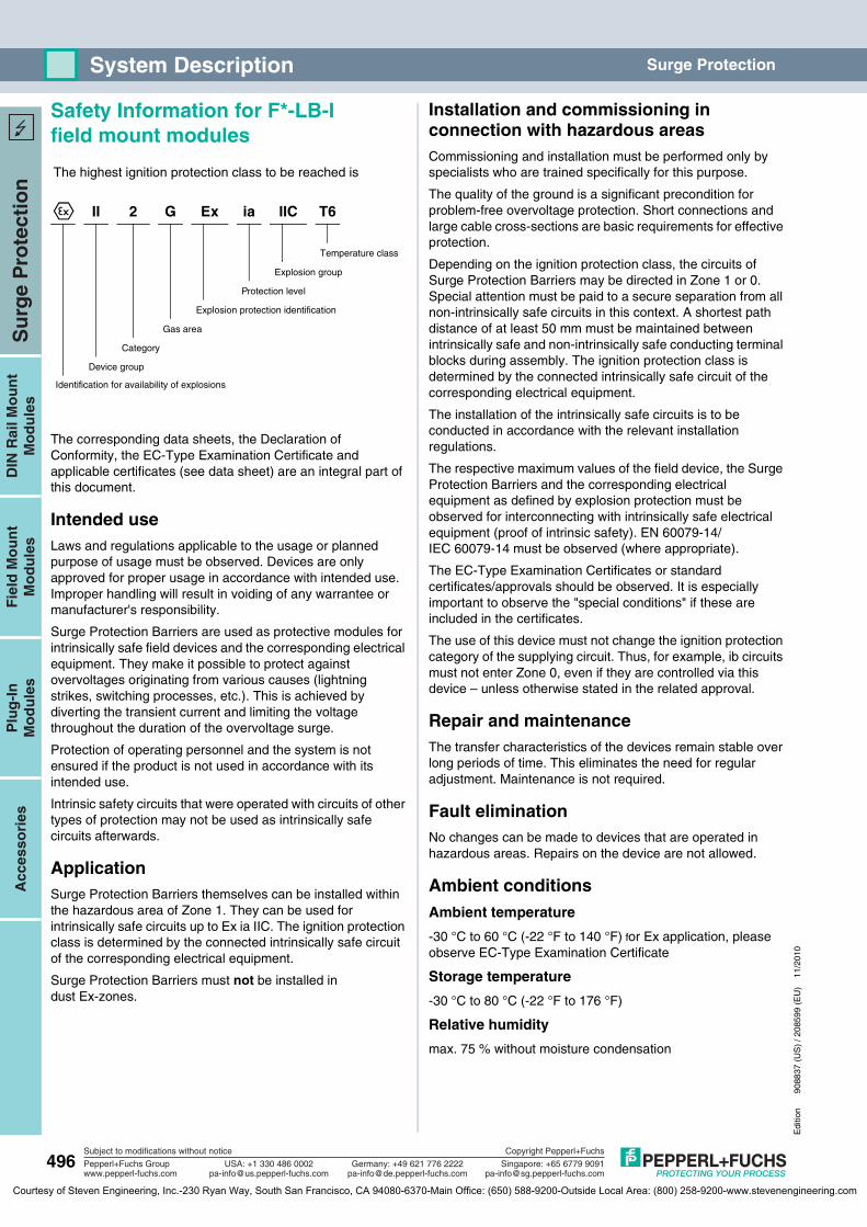
Safety Information for F*-LB-I field mount modules
The corresponding data sheets, the Declaration of Conformity, the EC-Type Examination Certificate and applicable certificates (see data sheet) are an integral part of this document.
Intended useLaws and regulations applicable to the usage or planned purpose of usage must be observed. Devices are only approved for proper usage in accordance with intended use. Improper handling will result in voiding of any warrantee or manufacturer's responsibility.
Surge Protection Barriers are used as protective modules for intrinsically safe field devices and the corresponding electrical equipment. They make it possible to protect against overvoltages originating from various causes (lightning strikes, switching processes, etc.). This is achieved by diverting the transient current and limiting the voltage throughout the duration of the overvoltage surge.
Protection of operating personnel and the system is not ensured if the product is not used in accordance with its intended use.
Intrinsic safety circuits that were operated with circuits of other types of protection may not be used as intrinsically safe circuits afterwards.
ApplicationSurge Protection Barriers themselves can be installed within the hazardous area of Zone 1. They can be used for intrinsically safe circuits up to Ex ia IIC. The ignition protection class is determined by the connected intrinsically safe circuit of the corresponding electrical equipment.
Surge Protection Barriers must not be installed in dust Ex-zones.
Installation and commissioning in connection with hazardous areasCommissioning and installation must be performed only by specialists who are trained specifically for this purpose.
The quality of the ground is a significant precondition for problem-free overvoltage protection. Short connections and large cable cross-sections are basic requirements for effective protection.
Depending on the ignition protection class, the circuits of Surge Protection Barriers may be directed in Zone 1 or 0. Special attention must be paid to a secure separation from all non-intrinsically safe circuits in this context. A shortest path distance of at least 50 mm must be maintained between intrinsically safe and non-intrinsically safe conducting terminal blocks during assembly. The ignition protection class is determined by the connected intrinsically safe circuit of the corresponding electrical equipment.
The installation of the intrinsically safe circuits is to be conducted in accordance with the relevant installation regulations.
The respective maximum values of the field device, the Surge Protection Barriers and the corresponding electrical equipment as defined by explosion protection must be observed for interconnecting with intrinsically safe electrical equipment (proof of intrinsic safety). EN 60079-14/IEC 60079-14 must be observed (where appropriate).
The EC-Type Examination Certificates or standard certificates/approvals should be observed. It is especially important to observe the "special conditions" if these are included in the certificates.
The use of this device must not change the ignition protection category of the supplying circuit. Thus, for example, ib circuits must not enter Zone 0, even if they are controlled via this device – unless otherwise stated in the related approval.
Repair and maintenanceThe transfer characteristics of the devices remain stable over long periods of time. This eliminates the need for regular adjustment. Maintenance is not required.
Fault eliminationNo changes can be made to devices that are operated in hazardous areas. Repairs on the device are not allowed.
Ambient conditionsAmbient temperature
-30 °C to 60 °C (-22 °F to 140 °F) for Ex application, please observe EC-Type Examination Certificate
Storage temperature
-30 °C to 80 °C (-22 °F to 176 °F)
Relative humidity
max. 75 % without moisture condensation
The highest ignition protection class to be reached is
¬ II 2 G Ex ia IIC T6
Temperature class
Explosion group
Protection level
Explosion protection identification
Gas area
Category
Device group
Identification for availability of explosions
Courtesy of Steven Engineering, Inc.-230 Ryan Way, South San Francisco, CA 94080-6370-Main Office: (650) 588-9200-Outside Local Area: (800) 258-9200-www.stevenengineering.com
Edi
tion
9088
37 (
US
) / 2
0859
9 (E
U)
11/2
010
497
Su
rge
Pro
tect
ion
Plu
g-I
nM
od
ule
sA
cces
sori
esD
IN R
ail M
ou
nt
Mo
du
les
Fie
ld M
ou
nt
Mo
du
les
Subject to modifications without notice
Pepperl+Fuchs Groupwww.pepperl-fuchs.com
USA: +1 330 486 [email protected] [email protected]
Singapore: +65 6779 [email protected]
Copyright Pepperl+Fuchs
Germany: +49 621 776 2222
System DescriptionSurge Protection
Safety Information for P-LB-*.*.* plug-in modules The corresponding data sheets, the Declaration of Conformity, the EC-Type Examination Certificate and applicable certificates (see data sheet) are an integral part of this document.
Intended useLaws and regulations applicable to the usage or planned purpose of usage must be observed. Devices are only approved for proper usage in accordance with intended use. Improper handling will result in voiding of any warrantee or manufacturer's responsibility.
Plug-in terminal modules are used as modules positioned upstream in the circuit from the corresponding electrical equipment. They make it possible to protect against overvoltages originating from various causes (lightning strikes, switching processes, etc.). This is achieved by diverting the transient current and limiting the voltage throughout the duration of the overvoltage surge. Various modules are available for protecting 2, 3, 4 or 6 conductors. The assignment of input connections of plug-in terminal modules/intrinsically safe equipment (binary or analog signals) corresponds to that of the following related equipment (see the corresponding data sheets). Plug-in terminal modules should only be used in combination with a device of the K-System.
Protection of operating personnel and the system is not ensured if the product is not used in accordance with its intended use.
Intrinsic safety circuits that were operated with circuits of other types of protection may not be used as intrinsically safe circuits afterwards.
ApplicationPlug-in terminal modules can be installed within the hazardous area of Zone 2/Div. 2. They can be used for intrinsically safe circuits up to Ex ia IIC. The ignition protection class is determined by the connected intrinsically safe circuit of the corresponding electrical equipment.
Plug-in terminal modules are not used to separate intrinsically safe circuits from non-intrinsically safe circuits.
Plug-in terminal modules must not be installed in dust Ex-zones.
Installation and commissioning in connection with hazardous areasCommissioning and installation must be performed only by specialists who are trained specifically for this purpose.
The quality of the ground is a significant precondition for problem-free overvoltage protection. Short connections and large cable cross-sections are basic requirements for effective protection. These requirements can be fulfilled through the use of appropriate accessories (see data sheets).
Plug-in terminal modules are designed in the IP20 protection class in accordance with EN 60529 and must be accordingly protected against adverse environmental conditions such as splashed water or dirt beyond pollution degree 2.
Plug-in terminal modules can be installed inside the hazardous area of Zone 2/Div. 2. Since plug-in terminal modules are always used in combination with devices of the K-System, the devices of the K-System must, in this case, be suitable for use in Zone 2/Div. 2. The devices of the K-System must then be installed only in Zone 2/Div. 2 if a corresponding Declaration of Conformity for a named location or a manufacturer's Declaration of Conformity is present. For information on whether this condition has been met, please refer to the data sheets for the devices of the K-System. The instruction manual, the Declaration of Conformity of a named location or the manufacturer's Declaration of Conformity of devices of the K-System and the information in them must be followed.
Depending on the ignition protection class, the circuits of plug-in terminal modules may be directed in Zone 1 or 0. Special attention must be paid to a secure separation from all non-intrinsically safe circuits in this context. A shortest path distance of at least 50 mm must be maintained between intrinsically safe and non-intrinsically safe conducting terminal blocks during assembly. The ignition protection class is determined by the connected intrinsically safe circuit of the corresponding electrical equipment.
The installation of the intrinsically safe circuits is to be conducted in accordance with the relevant installation regulations.
The respective maximum values of the field device, the plug-in terminal modules and the corresponding electrical equipment as defined by explosion protection must be observed for interconnecting with intrinsically safe electrical equipment (proof of intrinsic safety). EN 60079-14/IEC 60079-14 must be observed (where appropriate).
Courtesy of Steven Engineering, Inc.-230 Ryan Way, South San Francisco, CA 94080-6370-Main Office: (650) 588-9200-Outside Local Area: (800) 258-9200-www.stevenengineering.com
498
Edi
tion
9088
37 (
US
) / 2
0859
9 (E
U)
11/2
010
Su
rge
Pro
tect
ion
Plu
g-I
nM
od
ule
sA
cces
sori
esD
IN R
ail M
ou
nt
Mo
du
les
Fie
ld M
ou
nt
Mo
du
les
Subject to modifications without notice
Pepperl+Fuchs Groupwww.pepperl-fuchs.com
USA: +1 330 486 [email protected] [email protected]
Singapore: +65 6779 [email protected]
Copyright Pepperl+Fuchs
Germany: +49 621 776 2222
System Description Surge Protection
The EC-Type Examination Certificates or standard certificates/approvals should be observed. It is especially important to observe the "special conditions" if these are included in the certificates.
The terminal modules must be installed in such a way that they are protected from electrostatic charge.
The use of this device must not change the ignition protection category of the supplying circuit. Thus, for example, ib circuits must not enter Zone 0, even if they are controlled via this device – unless otherwise stated in the related approval.
Repair and maintenanceThe transfer characteristics of the devices remain stable over long periods of time. This eliminates the need for regular adjustment. Maintenance is not required.
Fault eliminationNo changes can be made to devices that are operated in hazardous areas. Repairs on the device are not allowed.
Isolation coordinates for devices with Ex-certificate in accordance with EN 50020 and EN 60079-11The devices are assessed for pollution degree 2 and overvoltage category II according to EN 50178.
Ambient conditionsAmbient temperature
-20 °C to 60 °C (-4 °F to 140 °F)
Storage temperature
-30 °C to 80 °C (-22 °F to 176 °F)
Relative humidity
max. 75 % without moisture condensation
Technical dataFor additional details, see data sheets.
Courtesy of Steven Engineering, Inc.-230 Ryan Way, South San Francisco, CA 94080-6370-Main Office: (650) 588-9200-Outside Local Area: (800) 258-9200-www.stevenengineering.com
Edi
tion
9088
37 (
US
) / 2
0859
9 (E
U)
11/2
010
499
Su
rge
Pro
tect
ion
Plu
g-I
nM
od
ule
sA
cces
sori
esD
IN R
ail M
ou
nt
Mo
du
les
Fie
ld M
ou
nt
Mo
du
les
Subject to modifications without notice
Pepperl+Fuchs Groupwww.pepperl-fuchs.com
USA: +1 330 486 [email protected] [email protected]
Singapore: +65 6779 [email protected]
Copyright Pepperl+Fuchs
Germany: +49 621 776 2222
Selection TablesSurge Protection
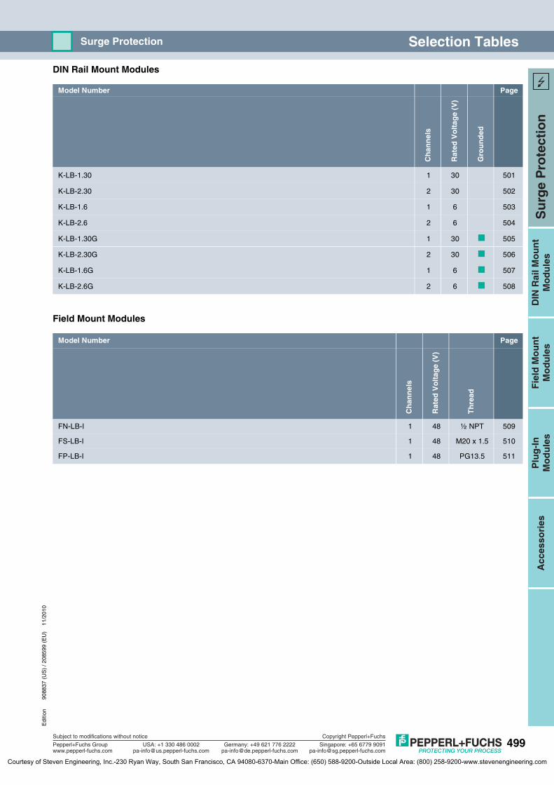
DIN Rail Mount Modules
Field Mount Modules
Model Number Page
Ch
ann
els
Rat
ed V
olt
age
(V)
Gro
un
ded
K-LB-1.30 1 30 501
K-LB-2.30 2 30 502
K-LB-1.6 1 6 503
K-LB-2.6 2 6 504
K-LB-1.30G 1 30 505
K-LB-2.30G 2 30 506
K-LB-1.6G 1 6 507
K-LB-2.6G 2 6 508
Model Number Page
Ch
ann
els
Rat
ed V
olt
age
(V)
Th
read
FN-LB-I 1 48 ½ NPT 509
FS-LB-I 1 48 M20 x 1.5 510
FP-LB-I 1 48 PG13.5 511
Courtesy of Steven Engineering, Inc.-230 Ryan Way, South San Francisco, CA 94080-6370-Main Office: (650) 588-9200-Outside Local Area: (800) 258-9200-www.stevenengineering.com
500
Edi
tion
9088
37 (
US
) / 2
0859
9 (E
U)
11/2
010
Su
rge
Pro
tect
ion
Plu
g-I
nM
od
ule
sA
cces
sori
esD
IN R
ail M
ou
nt
Mo
du
les
Fie
ld M
ou
nt
Mo
du
les
Subject to modifications without notice
Pepperl+Fuchs Groupwww.pepperl-fuchs.com
USA: +1 330 486 [email protected] [email protected]
Singapore: +65 6779 [email protected]
Copyright Pepperl+Fuchs
Germany: +49 621 776 2222
Selection Tables Surge Protection
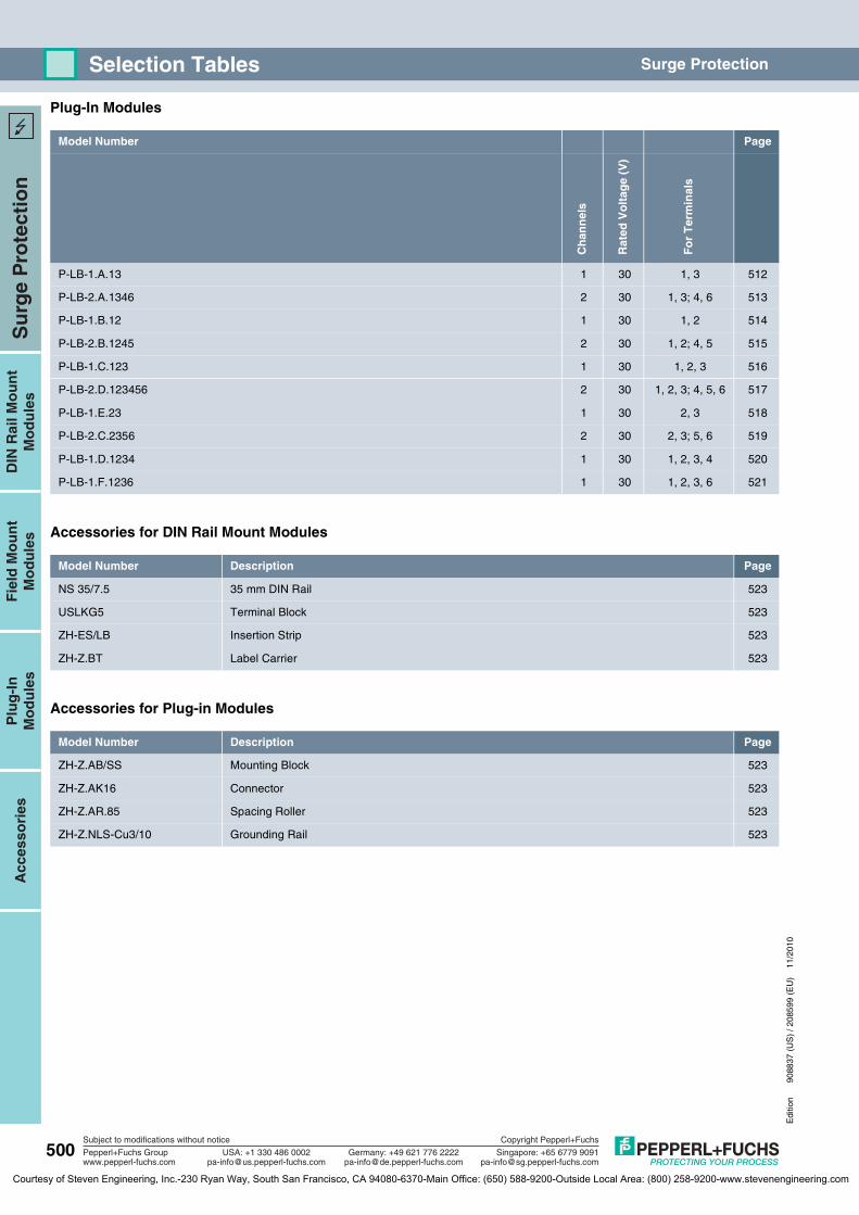
Plug-In Modules
Accessories for DIN Rail Mount Modules
Accessories for Plug-in Modules
Model Number Page
Ch
ann
els
Rat
ed V
olt
age
(V)
Fo
r T
erm
inal
s
P-LB-1.A.13 1 30 1, 3 512
P-LB-2.A.1346 2 30 1, 3; 4, 6 513
P-LB-1.B.12 1 30 1, 2 514
P-LB-2.B.1245 2 30 1, 2; 4, 5 515
P-LB-1.C.123 1 30 1, 2, 3 516
P-LB-2.D.123456 2 30 1, 2, 3; 4, 5, 6 517
P-LB-1.E.23 1 30 2, 3 518
P-LB-2.C.2356 2 30 2, 3; 5, 6 519
P-LB-1.D.1234 1 30 1, 2, 3, 4 520
P-LB-1.F.1236 1 30 1, 2, 3, 6 521
Model Number Description Page
NS 35/7.5 35 mm DIN Rail 523
USLKG5 Terminal Block 523
ZH-ES/LB Insertion Strip 523
ZH-Z.BT Label Carrier 523
Model Number Description Page
ZH-Z.AB/SS Mounting Block 523
ZH-Z.AK16 Connector 523
ZH-Z.AR.85 Spacing Roller 523
ZH-Z.NLS-Cu3/10 Grounding Rail 523
Courtesy of Steven Engineering, Inc.-230 Ryan Way, South San Francisco, CA 94080-6370-Main Office: (650) 588-9200-Outside Local Area: (800) 258-9200-www.stevenengineering.com

Features
Diagrams
Edi
tion
9088
37 (
US
) / 2
0859
9 (E
U)
11/2
010
501
Su
rge
Pro
tect
ion
Plu
g-I
nM
od
ule
sD
IN R
ail M
ou
nt
Mo
du
les
Fie
ld M
ou
nt
Mo
du
les
Acc
esso
ries
Subject to modifications without notice
Pepperl+Fuchs Groupwww.pepperl-fuchs.com
USA: +1 330 486 [email protected] [email protected]
Singapore: +65 6779 [email protected]
Copyright Pepperl+Fuchs
Germany: +49 621 776 2222
K-LB-1.30Surge Protection Barrier
• 1-channel• DIN rail mount module• For 30 V IS or Non-IS applications• Protects field or control circuit
inputs• Surge protection up to 10 kA• Provides 500 V DC of isolation• Uninterruptable operation
(auto reset)
Function
This Surge Protection Barrier limits induced transients of different origin (e. g. lightning stroke, switching impulse, etc.). This is achieved by diverting the transient current to ground and limiting the signal line voltage to a safe level for the duration of the surge.
This barrier provides low 45 V line-to-line and 500 V line-to-ground clamping voltage for the protected instruments. It also protects instruments that have more than 500 V isolation-to-ground, such as intrinsic safety isolated barriers, signal conditioners and most field instruments.
For additional information, refer to the manual and www.pepperl-fuchs.com.
Note: Surge Protection Barriers must always be connected to a solid and effective ground and be at the same equipotential level as the instrument it is protecting. The ground system must comply with all applicable regulations.
Technical dataSupplyConnection terminals 7, 8; 1, 2
Rated voltage ≤ 30 V
Rated current ≤ 250 mA
Leakage current ≤ 5 μA
On-state voltage ≤ 45 V
Ground insulation 500 V breakdown voltage
Ambient conditionsAmbient temperature -30 ... 60 °C (-22 ... 140 °F) for Ex application, please
observe EC-Type Examination Certificate
Mechanical specificationsProtection degree IP20
Mass approx. 100 g
Dimensions 12.5 x 114 x 110 mm (0.5 x 4.5 x 4.3 in)
Data for application in connection with Ex-areas
see page 522 for entity parameters
EC-Type Examination Certificate PTB 00 ATEX 2176X
Group, category, type of protection, temperature classification
¬ II 2(1)G Ex ia IIC T6
CSA approval
Control drawing 116-0187 (cCSAus)
K-LB-1.30
2
1
8
7
Zone 1, 2Div. 1, 2
Zone 0, 1, 2Div. 1, 2
5 67 8
1 23 4
Front view
Shield and groundconnection
Tag holder
Terminalsnot protected
Terminalsprotected
K-LB-1.30
Courtesy of Steven Engineering, Inc.-230 Ryan Way, South San Francisco, CA 94080-6370-Main Office: (650) 588-9200-Outside Local Area: (800) 258-9200-www.stevenengineering.com

Features
Diagrams
502
Edi
tion
9088
37 (
US
) / 2
0859
9 (E
U)
11/2
010
Su
rge
Pro
tect
ion
Plu
g-I
nM
od
ule
sD
IN R
ail M
ou
nt
Mo
du
les
Fie
ld M
ou
nt
Mo
du
les
Acc
esso
ries
Subject to modifications without notice
Pepperl+Fuchs Groupwww.pepperl-fuchs.com
USA: +1 330 486 [email protected] [email protected]
Singapore: +65 6779 [email protected]
Copyright Pepperl+Fuchs
Germany: +49 621 776 2222
K-LB-2.30 Surge Protection Barrier
• 2-channel• DIN rail mount module• For 30 V IS or Non-IS applications• Protects field or control circuit
inputs• Surge protection up to 10 kA• Provides 500 V DC of isolation• Uninterruptable operation
(auto reset)
Function
This Surge Protection Barrier limits induced transients of different origin (e. g. lightning stroke, switching impulse, etc.). This is achieved by diverting the transient current to ground and limiting the signal line voltage to a safe level for the duration of the surge.
This barrier provides low 45 V line-to-line and 500 V line-to-ground clamping voltage for the protected instruments. It also protects instruments that have more than 500 V isolation-to-ground, such as intrinsic safety isolated barriers, signal conditioners and most field instruments.
For additional information, refer to the manual and www.pepperl-fuchs.com.
Note: Surge Protection Barriers must always be connected to a solid and effective ground and be at the same equipotential level as the instrument it is protecting. The ground system must comply with all applicable regulations.
Technical dataSupplyConnection terminals 1, 2; 7, 8/3, 4; 5, 6
Rated voltage ≤ 30 V
Rated current ≤ 250 mA
Leakage current ≤ 5 μA
On-state voltage ≤ 45 V
Ground insulation 500 V breakdown voltage
Ambient conditionsAmbient temperature -30 ... 60 °C (-22 ... 140 °F) for Ex application, please
observe EC-Type Examination Certificate
Mechanical specificationsProtection degree IP20
Mass approx. 100 g
Dimensions 12.5 x 114 x 110 mm (0.5 x 4.5 x 4.3 in)
Data for application in connection with Ex-areas
see page 522 for entity parameters
EC-Type Examination Certificate PTB 00 ATEX 2176X
Group, category, type of protection, temperature classification
¬ II 2(1)G Ex ia IIC T6
CSA approval
Control drawing 116-0187 (cCSAus)
K-LB-2.30
2
1
4
3
8
7
5
6
Zone 1, 2Div. 1, 2
Zone 0, 1, 2Div. 1, 2
5 67 8
1 23 4
Front view
Shield and groundconnection
Tag holder
Terminalsnot protected
Terminalsprotected
K-LB-2.30
Courtesy of Steven Engineering, Inc.-230 Ryan Way, South San Francisco, CA 94080-6370-Main Office: (650) 588-9200-Outside Local Area: (800) 258-9200-www.stevenengineering.com
Features
Diagrams
Edi
tion
9088
37 (
US
) / 2
0859
9 (E
U)
11/2
010
503
Su
rge
Pro
tect
ion
Plu
g-I
nM
od
ule
sD
IN R
ail M
ou
nt
Mo
du
les
Fie
ld M
ou
nt
Mo
du
les
Acc
esso
ries
Subject to modifications without notice
Pepperl+Fuchs Groupwww.pepperl-fuchs.com
USA: +1 330 486 [email protected] [email protected]
Singapore: +65 6779 [email protected]
Copyright Pepperl+Fuchs
Germany: +49 621 776 2222
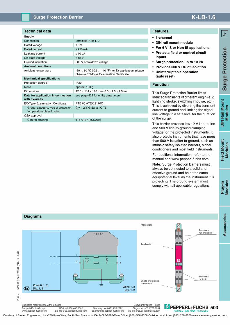
K-LB-1.6Surge Protection Barrier
• 1-channel• DIN rail mount module• For 6 V IS or Non-IS applications• Protects field or control circuit
inputs• Surge protection up to 10 kA• Provides 500 V DC of isolation• Uninterruptable operation
(auto reset)
Function
This Surge Protection Barrier limits induced transients of different origin (e. g. lightning stroke, switching impulse, etc.). This is achieved by diverting the transient current to ground and limiting the signal line voltage to a safe level for the duration of the surge.
This barrier provides low 12 V line-to-line and 500 V line-to-ground clamping voltage for the protected instruments. It also protects instruments that have more than 500 V isolation-to-ground, such as intrinsic safety isolated barriers, signal conditioners and most field instruments.
For additional information, refer to the manual and www.pepperl-fuchs.com.
Note: Surge Protection Barriers must always be connected to a solid and effective ground and be at the same equipotential level as the instrument it is protecting. The ground system must comply with all applicable regulations.
Technical dataSupplyConnection terminals 7, 8; 1, 2
Rated voltage ≤ 6 V
Rated current ≤ 250 mA
Leakage current ≤ 10 μA
On-state voltage ≤ 12 V
Ground insulation 500 V breakdown voltage
Ambient conditionsAmbient temperature -30 ... 60 °C (-22 ... 140 °F) for Ex application, please
observe EC-Type Examination Certificate
Mechanical specificationsProtection degree IP20
Mass approx. 100 g
Dimensions 12.5 x 114 x 110 mm (0.5 x 4.5 x 4.3 in)
Data for application in connection with Ex-areas
see page 522 for entity parameters
EC-Type Examination Certificate PTB 00 ATEX 2176X
Group, category, type of protection, temperature classification
¬ II 2(1)G Ex ia IIC T6
CSA approval
Control drawing 116-0187 (cCSAus)
K-LB-1.6
2
1
8
7
Zone 1, 2Div. 1, 2
Zone 0, 1, 2Div. 1, 2
5 67 8
1 23 4
Front view
Shield and groundconnection
Tag holder
Terminalsnot protected
Terminalsprotected
K-LB-1.6
Courtesy of Steven Engineering, Inc.-230 Ryan Way, South San Francisco, CA 94080-6370-Main Office: (650) 588-9200-Outside Local Area: (800) 258-9200-www.stevenengineering.com
Features
Diagrams
504
Edi
tion
9088
37 (
US
) / 2
0859
9 (E
U)
11/2
010
Su
rge
Pro
tect
ion
Plu
g-I
nM
od
ule
sD
IN R
ail M
ou
nt
Mo
du
les
Fie
ld M
ou
nt
Mo
du
les
Acc
esso
ries
Subject to modifications without notice
Pepperl+Fuchs Groupwww.pepperl-fuchs.com
USA: +1 330 486 [email protected] [email protected]
Singapore: +65 6779 [email protected]
Copyright Pepperl+Fuchs
Germany: +49 621 776 2222
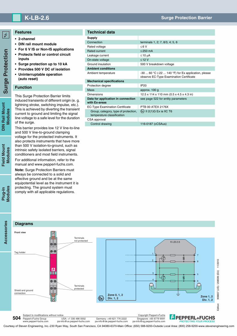
K-LB-2.6 Surge Protection Barrier
• 2-channel• DIN rail mount module• For 6 V IS or Non-IS applications• Protects field or control circuit
inputs• Surge protection up to 10 kA• Provides 500 V DC of isolation• Uninterruptable operation
(auto reset)
Function
This Surge Protection Barrier limits induced transients of different origin (e. g. lightning stroke, switching impulse, etc.). This is achieved by diverting the transient current to ground and limiting the signal line voltage to a safe level for the duration of the surge.
This barrier provides low 12 V line-to-line and 500 V line-to-ground clamping voltage for the protected instruments. It also protects instruments that have more than 500 V isolation-to-ground, such as intrinsic safety isolated barriers, signal conditioners and most field instruments.
For additional information, refer to the manual and www.pepperl-fuchs.com.
Note: Surge Protection Barriers must always be connected to a solid and effective ground and be at the same equipotential level as the instrument it is protecting. The ground system must comply with all applicable regulations.
Technical dataSupplyConnection terminals 1, 2; 7, 8/3, 4; 5, 6
Rated voltage ≤ 6 V
Rated current ≤ 250 mA
Leakage current ≤ 10 μA
On-state voltage ≤ 12 V
Ground insulation 500 V breakdown voltage
Ambient conditionsAmbient temperature -30 ... 60 °C (-22 ... 140 °F) for Ex application, please
observe EC-Type Examination Certificate
Mechanical specificationsProtection degree IP20
Mass approx. 100 g
Dimensions 12.5 x 114 x 110 mm (0.5 x 4.5 x 4.3 in)
Data for application in connection with Ex-areas
see page 522 for entity parameters
EC-Type Examination Certificate PTB 00 ATEX 2176X
Group, category, type of protection, temperature classification
¬ II 2(1)G Ex ia IIC T6
CSA approval
Control drawing 116-0187 (cCSAus)
K-LB-2.6
2
1
4
3
8
7
5
6
Zone 1, 2Div. 1, 2
Zone 0, 1, 2Div. 1, 2
5 67 8
1 23 4
Front view
Shield and groundconnection
Tag holder
Terminalsnot protected
Terminalsprotected
K-LB-2.6
Courtesy of Steven Engineering, Inc.-230 Ryan Way, South San Francisco, CA 94080-6370-Main Office: (650) 588-9200-Outside Local Area: (800) 258-9200-www.stevenengineering.com

Features
Diagrams
Edi
tion
9088
37 (
US
) / 2
0859
9 (E
U)
11/2
010
505
Su
rge
Pro
tect
ion
Plu
g-I
nM
od
ule
sD
IN R
ail M
ou
nt
Mo
du
les
Fie
ld M
ou
nt
Mo
du
les
Acc
esso
ries
Subject to modifications without notice
Pepperl+Fuchs Groupwww.pepperl-fuchs.com
USA: +1 330 486 [email protected] [email protected]
Singapore: +65 6779 [email protected]
Copyright Pepperl+Fuchs
Germany: +49 621 776 2222
K-LB-1.30GSurge Protection Barrier
• 1-channel• DIN rail mount module• For 30 V IS or Non-IS applications• Protects field or control circuit
inputs• Surge protection up to 10 kA• Uninterruptable operation
(auto reset)
Function
This Surge Protection Barrier limits induced transients of different origin (e. g. lightning stroke, switching impulse, etc.). This is achieved by diverting the transient current to ground and limiting the signal line voltage to a safe level for the duration of the surge.
This barrier provides a low line-to-line and line-to-ground clamping voltage for the protected instrument. It also protects instruments that have less than 500 V isolation-to-ground, such as Zener Barriers, standard I/O cards, and some field instruments.
For additional information, refer to the manual and www.pepperl-fuchs.com.
Note: Surge Protection Barriers must always be connected to a solid and effective ground and be at the same equipotential level as the instrument it is protecting. The ground system must comply with all applicable regulations.
Technical dataSupplyConnection terminals 7, 8; 1, 2
Rated voltage ≤ 30 V
Rated current ≤ 250 mA
Leakage current ≤ 5 μA
On-state voltage ≤ 45 V
Ambient conditionsAmbient temperature -30 ... 60 °C (-22 ... 140 °F) for Ex application, please
observe EC-Type Examination Certificate
Mechanical specificationsProtection degree IP20
Mass approx. 100 g
Dimensions 12.5 x 114 x 110 mm (0.5 x 4.5 x 4.3 in)
Data for application in connection with Ex-areas
see page 522 for entity parameters
EC-Type Examination Certificate PTB 00 ATEX 2176X
Group, category, type of protection, temperature classification
¬ II 2(1)G Ex ia IIC T6
CSA approval
Control drawing 116-0187 (cCSAus)
K-LB-1.30G
2
1
8
7
Zone 1, 2Div. 1, 2
Zone 0, 1, 2Div. 1, 2
5 67 8
1 23 4
Front view
Shield and groundconnection
Tag holder
Terminalsnot protected
Terminalsprotected
K-LB-1.30G
Courtesy of Steven Engineering, Inc.-230 Ryan Way, South San Francisco, CA 94080-6370-Main Office: (650) 588-9200-Outside Local Area: (800) 258-9200-www.stevenengineering.com
Features
Diagrams
506
Edi
tion
9088
37 (
US
) / 2
0859
9 (E
U)
11/2
010
Su
rge
Pro
tect
ion
Plu
g-I
nM
od
ule
sD
IN R
ail M
ou
nt
Mo
du
les
Fie
ld M
ou
nt
Mo
du
les
Acc
esso
ries
Subject to modifications without notice
Pepperl+Fuchs Groupwww.pepperl-fuchs.com
USA: +1 330 486 [email protected] [email protected]
Singapore: +65 6779 [email protected]
Copyright Pepperl+Fuchs
Germany: +49 621 776 2222
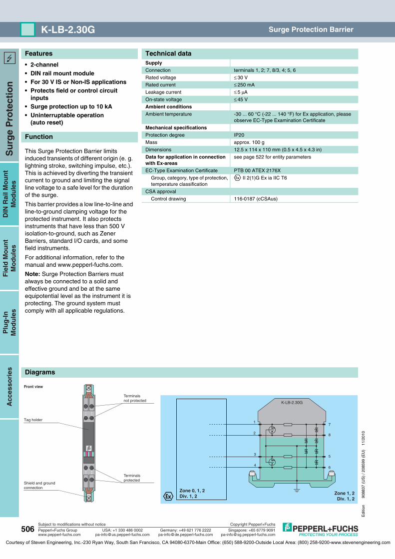
K-LB-2.30G Surge Protection Barrier
• 2-channel• DIN rail mount module• For 30 V IS or Non-IS applications• Protects field or control circuit
inputs• Surge protection up to 10 kA• Uninterruptable operation
(auto reset)
Function
This Surge Protection Barrier limits induced transients of different origin (e. g. lightning stroke, switching impulse, etc.). This is achieved by diverting the transient current to ground and limiting the signal line voltage to a safe level for the duration of the surge.
This barrier provides a low line-to-line and line-to-ground clamping voltage for the protected instrument. It also protects instruments that have less than 500 V isolation-to-ground, such as Zener Barriers, standard I/O cards, and some field instruments.
For additional information, refer to the manual and www.pepperl-fuchs.com.
Note: Surge Protection Barriers must always be connected to a solid and effective ground and be at the same equipotential level as the instrument it is protecting. The ground system must comply with all applicable regulations.
Technical dataSupplyConnection terminals 1, 2; 7, 8/3, 4; 5, 6
Rated voltage ≤ 30 V
Rated current ≤ 250 mA
Leakage current ≤ 5 μA
On-state voltage ≤ 45 V
Ambient conditionsAmbient temperature -30 ... 60 °C (-22 ... 140 °F) for Ex application, please
observe EC-Type Examination Certificate
Mechanical specificationsProtection degree IP20
Mass approx. 100 g
Dimensions 12.5 x 114 x 110 mm (0.5 x 4.5 x 4.3 in)
Data for application in connection with Ex-areas
see page 522 for entity parameters
EC-Type Examination Certificate PTB 00 ATEX 2176X
Group, category, type of protection, temperature classification
¬ II 2(1)G Ex ia IIC T6
CSA approval
Control drawing 116-0187 (cCSAus)
K-LB-2.30G
2
1
4
3
8
7
5
6
Zone 1, 2Div. 1, 2
Zone 0, 1, 2Div. 1, 2
5 67 8
1 23 4
Front view
Shield and groundconnection
Tag holder
Terminalsnot protected
Terminalsprotected
K-LB-2.30G
Courtesy of Steven Engineering, Inc.-230 Ryan Way, South San Francisco, CA 94080-6370-Main Office: (650) 588-9200-Outside Local Area: (800) 258-9200-www.stevenengineering.com
Features
Diagrams
Edi
tion
9088
37 (
US
) / 2
0859
9 (E
U)
11/2
010
507
Su
rge
Pro
tect
ion
Plu
g-I
nM
od
ule
sD
IN R
ail M
ou
nt
Mo
du
les
Fie
ld M
ou
nt
Mo
du
les
Acc
esso
ries
Subject to modifications without notice
Pepperl+Fuchs Groupwww.pepperl-fuchs.com
USA: +1 330 486 [email protected] [email protected]
Singapore: +65 6779 [email protected]
Copyright Pepperl+Fuchs
Germany: +49 621 776 2222
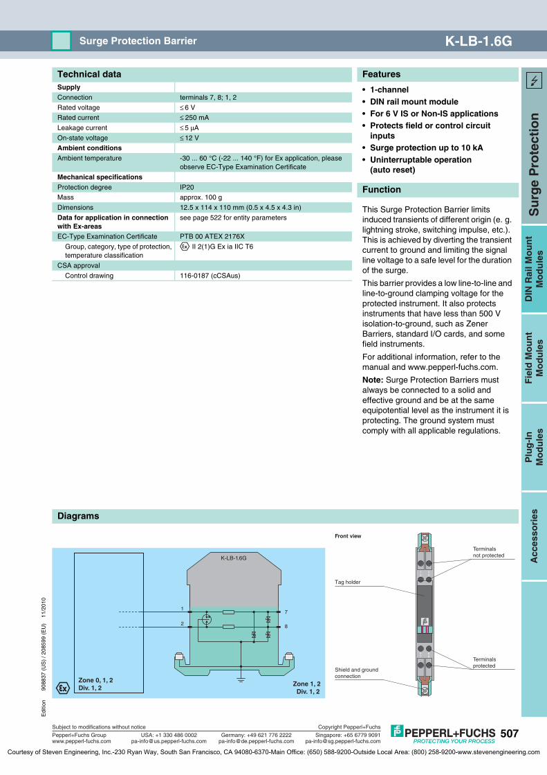
K-LB-1.6GSurge Protection Barrier
• 1-channel• DIN rail mount module• For 6 V IS or Non-IS applications• Protects field or control circuit
inputs• Surge protection up to 10 kA• Uninterruptable operation
(auto reset)
Function
This Surge Protection Barrier limits induced transients of different origin (e. g. lightning stroke, switching impulse, etc.). This is achieved by diverting the transient current to ground and limiting the signal line voltage to a safe level for the duration of the surge.
This barrier provides a low line-to-line and line-to-ground clamping voltage for the protected instrument. It also protects instruments that have less than 500 V isolation-to-ground, such as Zener Barriers, standard I/O cards, and some field instruments.
For additional information, refer to the manual and www.pepperl-fuchs.com.
Note: Surge Protection Barriers must always be connected to a solid and effective ground and be at the same equipotential level as the instrument it is protecting. The ground system must comply with all applicable regulations.
Technical dataSupplyConnection terminals 7, 8; 1, 2
Rated voltage ≤ 6 V
Rated current ≤ 250 mA
Leakage current ≤ 5 μA
On-state voltage ≤ 12 V
Ambient conditionsAmbient temperature -30 ... 60 °C (-22 ... 140 °F) for Ex application, please
observe EC-Type Examination Certificate
Mechanical specificationsProtection degree IP20
Mass approx. 100 g
Dimensions 12.5 x 114 x 110 mm (0.5 x 4.5 x 4.3 in)
Data for application in connection with Ex-areas
see page 522 for entity parameters
EC-Type Examination Certificate PTB 00 ATEX 2176X
Group, category, type of protection, temperature classification
¬ II 2(1)G Ex ia IIC T6
CSA approval
Control drawing 116-0187 (cCSAus)
K-LB-1.6G
2
1
8
7
Zone 1, 2Div. 1, 2
Zone 0, 1, 2Div. 1, 2
5 67 8
1 23 4
Front view
Shield and groundconnection
Tag holder
Terminalsnot protected
Terminalsprotected
K-LB-1.6G
Courtesy of Steven Engineering, Inc.-230 Ryan Way, South San Francisco, CA 94080-6370-Main Office: (650) 588-9200-Outside Local Area: (800) 258-9200-www.stevenengineering.com
Features
Diagrams
508
Edi
tion
9088
37 (
US
) / 2
0859
9 (E
U)
11/2
010
Su
rge
Pro
tect
ion
Plu
g-I
nM
od
ule
sD
IN R
ail M
ou
nt
Mo
du
les
Fie
ld M
ou
nt
Mo
du
les
Acc
esso
ries
Subject to modifications without notice
Pepperl+Fuchs Groupwww.pepperl-fuchs.com
USA: +1 330 486 [email protected] [email protected]
Singapore: +65 6779 [email protected]
Copyright Pepperl+Fuchs
Germany: +49 621 776 2222
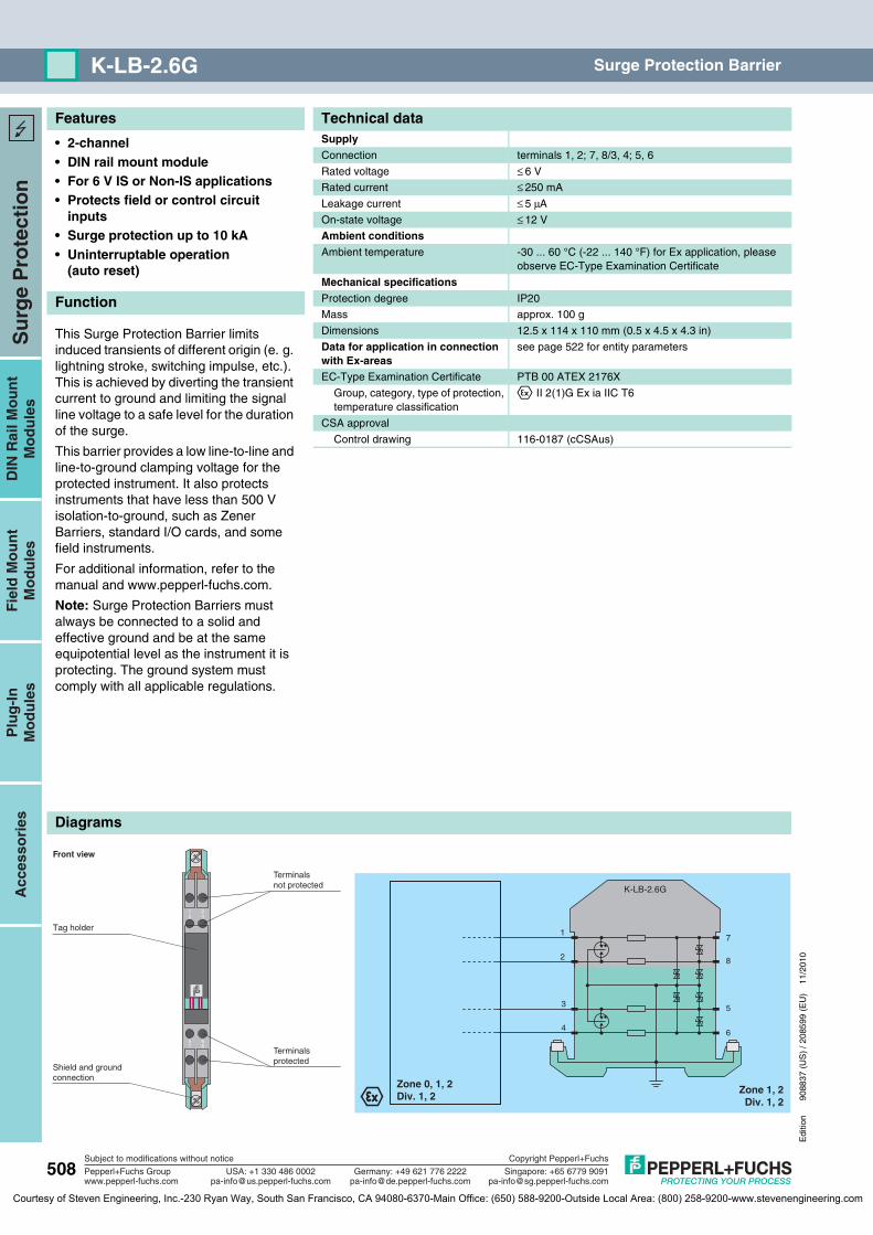
K-LB-2.6G Surge Protection Barrier
• 2-channel• DIN rail mount module• For 6 V IS or Non-IS applications• Protects field or control circuit
inputs• Surge protection up to 10 kA• Uninterruptable operation
(auto reset)
Function
This Surge Protection Barrier limits induced transients of different origin (e. g. lightning stroke, switching impulse, etc.). This is achieved by diverting the transient current to ground and limiting the signal line voltage to a safe level for the duration of the surge.
This barrier provides a low line-to-line and line-to-ground clamping voltage for the protected instrument. It also protects instruments that have less than 500 V isolation-to-ground, such as Zener Barriers, standard I/O cards, and some field instruments.
For additional information, refer to the manual and www.pepperl-fuchs.com.
Note: Surge Protection Barriers must always be connected to a solid and effective ground and be at the same equipotential level as the instrument it is protecting. The ground system must comply with all applicable regulations.
Technical dataSupplyConnection terminals 1, 2; 7, 8/3, 4; 5, 6
Rated voltage ≤ 6 V
Rated current ≤ 250 mA
Leakage current ≤ 5 μA
On-state voltage ≤ 12 V
Ambient conditionsAmbient temperature -30 ... 60 °C (-22 ... 140 °F) for Ex application, please
observe EC-Type Examination Certificate
Mechanical specificationsProtection degree IP20
Mass approx. 100 g
Dimensions 12.5 x 114 x 110 mm (0.5 x 4.5 x 4.3 in)
Data for application in connection with Ex-areas
see page 522 for entity parameters
EC-Type Examination Certificate PTB 00 ATEX 2176X
Group, category, type of protection, temperature classification
¬ II 2(1)G Ex ia IIC T6
CSA approval
Control drawing 116-0187 (cCSAus)
K-LB-2.6G
2
1
4
3
8
7
5
6
Zone 1, 2Div. 1, 2
Zone 0, 1, 2Div. 1, 2
5 67 8
1 23 4
Front view
Shield and groundconnection
Tag holder
Terminalsnot protected
Terminalsprotected
K-LB-2.6G
Courtesy of Steven Engineering, Inc.-230 Ryan Way, South San Francisco, CA 94080-6370-Main Office: (650) 588-9200-Outside Local Area: (800) 258-9200-www.stevenengineering.com
Features
Diagrams
Edi
tion
9088
37 (
US
) / 2
0859
9 (E
U)
11/2
010
509
Su
rge
Pro
tect
ion
Plu
g-I
nM
od
ule
sD
IN R
ail M
ou
nt
Mo
du
les
Fie
ld M
ou
nt
Mo
du
les
Acc
esso
ries
Subject to modifications without notice
Pepperl+Fuchs Groupwww.pepperl-fuchs.com
USA: +1 330 486 [email protected] [email protected]
Singapore: +65 6779 [email protected]
Copyright Pepperl+Fuchs
Germany: +49 621 776 2222
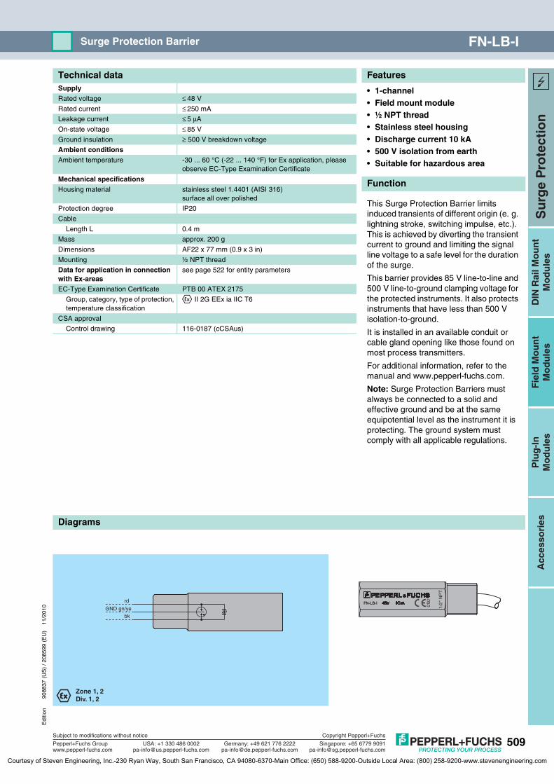
FN-LB-ISurge Protection Barrier
• 1-channel• Field mount module• ½ NPT thread• Stainless steel housing• Discharge current 10 kA• 500 V isolation from earth• Suitable for hazardous area
Function
This Surge Protection Barrier limits induced transients of different origin (e. g. lightning stroke, switching impulse, etc.). This is achieved by diverting the transient current to ground and limiting the signal line voltage to a safe level for the duration of the surge.
This barrier provides 85 V line-to-line and 500 V line-to-ground clamping voltage for the protected instruments. It also protects instruments that have less than 500 V isolation-to-ground.
It is installed in an available conduit or cable gland opening like those found on most process transmitters.
For additional information, refer to the manual and www.pepperl-fuchs.com.
Note: Surge Protection Barriers must always be connected to a solid and effective ground and be at the same equipotential level as the instrument it is protecting. The ground system must comply with all applicable regulations.
Technical dataSupplyRated voltage ≤ 48 V
Rated current ≤ 250 mA
Leakage current ≤ 5 μA
On-state voltage ≤ 85 V
Ground insulation ≥ 500 V breakdown voltage
Ambient conditionsAmbient temperature -30 ... 60 °C (-22 ... 140 °F) for Ex application, please
observe EC-Type Examination Certificate
Mechanical specificationsHousing material stainless steel 1.4401 (AISI 316)
surface all over polished
Protection degree IP20
Cable
Length L 0.4 m
Mass approx. 200 g
Dimensions AF22 x 77 mm (0.9 x 3 in)
Mounting ½ NPT thread
Data for application in connection with Ex-areas
see page 522 for entity parameters
EC-Type Examination Certificate PTB 00 ATEX 2175
Group, category, type of protection, temperature classification
¬ II 2G EEx ia IIC T6
CSA approval
Control drawing 116-0187 (cCSAus)
rd
bk
Zone 1, 2Div. 1, 2
GND gn/ye 1/2
" N
PT
FN-LB-I
FN-LB-I
Courtesy of Steven Engineering, Inc.-230 Ryan Way, South San Francisco, CA 94080-6370-Main Office: (650) 588-9200-Outside Local Area: (800) 258-9200-www.stevenengineering.com

Features
Diagrams
510
Edi
tion
9088
37 (
US
) / 2
0859
9 (E
U)
11/2
010
Su
rge
Pro
tect
ion
Plu
g-I
nM
od
ule
sD
IN R
ail M
ou
nt
Mo
du
les
Fie
ld M
ou
nt
Mo
du
les
Acc
esso
ries
Subject to modifications without notice
Pepperl+Fuchs Groupwww.pepperl-fuchs.com
USA: +1 330 486 [email protected] [email protected]
Singapore: +65 6779 [email protected]
Copyright Pepperl+Fuchs
Germany: +49 621 776 2222
FS-LB-I Surge Protection Barrier
• 1-channel• Field mount module• M20 x 1.5 thread• Stainless steel housing• Discharge current 10 kA• 500 V isolation from earth• Suitable for hazardous area
Function
This Surge Protection Barrier limits induced transients of different origin (e. g. lightning stroke, switching impulse, etc.). This is achieved by diverting the transient current to ground and limiting the signal line voltage to a safe level for the duration of the surge.
This barrier provides 85 V line-to-line and 500 V line-to-ground clamping voltage for the protected instruments. It also protects instruments that have less than 500 V isolation-to-ground.
It is installed in an available conduit or cable gland opening like those found on most process transmitters.
For additional information, refer to the manual and www.pepperl-fuchs.com.
Note: Surge Protection Barriers must always be connected to a solid and effective ground and be at the same equipotential level as the instrument it is protecting. The ground system must comply with all applicable regulations.
Technical dataSupplyRated voltage ≤ 48 V
Rated current ≤ 250 mA
Leakage current ≤ 5 μA
On-state voltage ≤ 85 V
Ground insulation ≥ 500 V breakdown voltage
Ambient conditionsAmbient temperature -30 ... 60 °C (-22 ... 140 °F) for Ex application, please
observe EC-Type Examination Certificate
Mechanical specificationsHousing material stainless steel 1.4401 (AISI 316)
surface all over polished
Protection degree IP20
Cable
Length L 0.4 m
Mass approx. 200 g
Dimensions AF22 x 77 mm (0.9 x 3 in)
Mounting M20 x 1.5 thread
Data for application in connection with Ex-areas
see page 522 for entity parameters
EC-Type Examination Certificate PTB 00 ATEX 2175
Group, category, type of protection, temperature classification
¬ II 2G EEx ia IIC T6
CSA approval
Control drawing 116-0187 (cCSAus)
rd
bk
Zone 1, 2Div. 1, 2
GND gn/yeM2
0x1
5
FS-LB-I
FS-LB-I
Courtesy of Steven Engineering, Inc.-230 Ryan Way, South San Francisco, CA 94080-6370-Main Office: (650) 588-9200-Outside Local Area: (800) 258-9200-www.stevenengineering.com

Features
Diagrams
Edi
tion
9088
37 (
US
) / 2
0859
9 (E
U)
11/2
010
511
Su
rge
Pro
tect
ion
Plu
g-I
nM
od
ule
sD
IN R
ail M
ou
nt
Mo
du
les
Fie
ld M
ou
nt
Mo
du
les
Acc
esso
ries
Subject to modifications without notice
Pepperl+Fuchs Groupwww.pepperl-fuchs.com
USA: +1 330 486 [email protected] [email protected]
Singapore: +65 6779 [email protected]
Copyright Pepperl+Fuchs
Germany: +49 621 776 2222
FP-LB-ISurge Protection Barrier
• 1-channel• Field mount module• PG13.5 thread• Stainless steel housing• Discharge current 10 kA• 500 V isolation from earth• Suitable for hazardous area
Function
This Surge Protection Barrier limits induced transients of different origin (e. g. lightning stroke, switching impulse, etc.). This is achieved by diverting the transient current to ground and limiting the signal line voltage to a safe level for the duration of the surge.
This barrier provides 85 V line-to-line and 500 V line-to-ground clamping voltage for the protected instruments. It also protects instruments that have less than 500 V isolation-to-ground.
It is installed in an available conduit or cable gland opening like those found on most process transmitters.
For additional information, refer to the manual and www.pepperl-fuchs.com.
Note: Surge Protection Barriers must always be connected to a solid and effective ground and be at the same equipotential level as the instrument it is protecting. The ground system must comply with all applicable regulations.
Technical dataSupplyRated voltage ≤ 48 V
Rated current ≤ 250 mA
Leakage current ≤ 5 μA
On-state voltage ≤ 85 V
Ground insulation ≥ 500 V breakdown voltage
Ambient conditionsAmbient temperature -30 ... 60 °C (-22 ... 140 °F) for Ex application, please
observe EC-Type Examination Certificate
Mechanical specificationsHousing material stainless steel 1.4401 (AISI 316)
surface all over polished
Protection degree IP20
Cable
Length L 0.4 m
Mass approx. 200 g
Dimensions AF22 x 77 mm (0.9 x 3 in)
Mounting PG13.5 thread
Data for application in connection with Ex-areas
see page 522 for entity parameters
EC-Type Examination Certificate PTB 00 ATEX 2175
Group, category, type of protection, temperature classification
¬ II 2G EEx ia IIC T6
CSA approval
Control drawing 116-0187 (cCSAus)
rd
bk
Zone 1, 2Div. 1, 2
GND gn/ye
Pg
13
,5
FP-LB-I
FP-LB-I
Courtesy of Steven Engineering, Inc.-230 Ryan Way, South San Francisco, CA 94080-6370-Main Office: (650) 588-9200-Outside Local Area: (800) 258-9200-www.stevenengineering.com

Features
Diagrams
512
Edi
tion
9088
37 (
US
) / 2
0859
9 (E
U)
11/2
010
Su
rge
Pro
tect
ion
Plu
g-I
nM
od
ule
sD
IN R
ail M
ou
nt
Mo
du
les
Fie
ld M
ou
nt
Mo
du
les
Acc
esso
ries
Subject to modifications without notice
Pepperl+Fuchs Groupwww.pepperl-fuchs.com
USA: +1 330 486 [email protected] [email protected]
Singapore: +65 6779 [email protected]
Copyright Pepperl+Fuchs
Germany: +49 621 776 2222
P-LB-1.A.13 Surge Protection Barrier
• 1-channel• Plugs directly in to field side of
KF modules• Analog or digital signal inputs• Surge protection up to 10 kA• Protects leads 1 and 3 of KF modules• Uninterruptable operation
(auto reset)
Function
This Surge Protection Barrier is designed for use with K-System (KF modules).
By simply snapping the barriers into a standard KF module, the modules are safely protected against voltage surges of different origin (e. g. lightning stroke, switching impulse, etc.). This is achieved by diverting the transient current to ground and limiting the signal line voltage to a safe level for the duration of the surge.
The end digits of the model designation correspond to the protected terminals of the respective KF module.
For additional information, refer to the manual and www.pepperl-fuchs.com.
Note: Surge Protection Barriers must always be connected to a solid and effective ground and be at the same equipotential level as the instrument it is protecting. The ground system must comply with all applicable regulations.
Technical dataSignal linesConnection terminals 1, 3
Rated voltage ≤ 30 V
Rated current ≤ 250 mA
Leakage current ≤ 5 μA
On-state voltage ≤ 45 V
Ground insulation ≤ 500 V breakdown voltage
Ambient conditionsAmbient temperature -20 ... 60 °C (-4 ... 140 °F)
Mechanical specificationsProtection degree IP20
Mass approx. 70 g
Dimensions 20 x 62 x 115 mm (0.8 x 2.4 x 4.5 in)
Data for application in connection with Ex-areas
see page 522 for entity parameters
EC-Type Examination Certificate PTB 02 ATEX 2044
Group, category, type of protection ¬ II (1)G [EEx ia] IIC
CSA approval
Control drawing 116-0187 (cCSAus)
P-LB-1.A.13
Zone 2Div. 2
Zone 0, 1, 2Div. 1, 2
(1)
(3)
1
3
Front view
Removable terminalblue, not protected
Connection to earth
Terminalsprotected
P-LB-1.A.13
Courtesy of Steven Engineering, Inc.-230 Ryan Way, South San Francisco, CA 94080-6370-Main Office: (650) 588-9200-Outside Local Area: (800) 258-9200-www.stevenengineering.com

Features
Diagrams
Edi
tion
9088
37 (
US
) / 2
0859
9 (E
U)
11/2
010
513
Su
rge
Pro
tect
ion
Plu
g-I
nM
od
ule
sD
IN R
ail M
ou
nt
Mo
du
les
Fie
ld M
ou
nt
Mo
du
les
Acc
esso
ries
Subject to modifications without notice
Pepperl+Fuchs Groupwww.pepperl-fuchs.com
USA: +1 330 486 [email protected] [email protected]
Singapore: +65 6779 [email protected]
Copyright Pepperl+Fuchs
Germany: +49 621 776 2222
P-LB-2.A.1346Surge Protection Barrier
• 2-channel• Plugs directly in to field side of
KF modules• Analog or digital signal inputs• Surge protection up to 10 kA• Protects leads 1, 3, 4 and 6 of
KF modules• Uninterruptable operation
(auto reset)
Function
This Surge Protection Barrier is designed for use with K-System (KF modules).
By simply snapping the barriers into a standard KF module, the modules are safely protected against voltage surges of different origin (e. g. lightning stroke, switching impulse, etc.). This is achieved by diverting the transient current to ground and limiting the signal line voltage to a safe level for the duration of the surge.
The end digits of the model designation correspond to the protected terminals of the respective KF module.
For additional information, refer to the manual and www.pepperl-fuchs.com.
Note: Surge Protection Barriers must always be connected to a solid and effective ground and be at the same equipotential level as the instrument it is protecting. The ground system must comply with all applicable regulations.
Technical dataSignal linesConnection terminals 1, 3; 4, 6
Rated voltage ≤ 30 V
Rated current ≤ 250 mA
Leakage current ≤ 5 μA
On-state voltage ≤ 45 V
Ground insulation ≤ 500 V breakdown voltage
Ambient conditionsAmbient temperature -20 ... 60 °C (-4 ... 140 °F)
Mechanical specificationsProtection degree IP20
Mass approx. 70 g
Dimensions 20 x 62 x 115 mm (0.8 x 2.4 x 4.5 in)
Data for application in connection with Ex-areas
see page 522 for entity parameters
EC-Type Examination Certificate PTB 02 ATEX 2044
Group, category, type of protection ¬ II (1)G [EEx ia] IIC
CSA approval
Control drawing 116-0187 (cCSAus)
P-LB-2.A.1346
Zone 2Div. 2
Zone 0, 1, 2Div. 1, 2
(1)
(3)
(4)
(6)
1
3
4
6
Front view
Removable terminalsblue, not protected
Connection to earth
Terminalsprotected
P-LB-2.A.1346
Courtesy of Steven Engineering, Inc.-230 Ryan Way, South San Francisco, CA 94080-6370-Main Office: (650) 588-9200-Outside Local Area: (800) 258-9200-www.stevenengineering.com
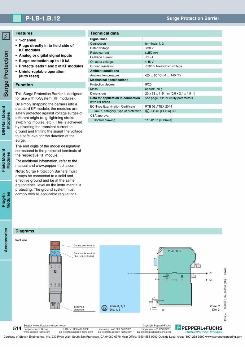
Features
Diagrams
514
Edi
tion
9088
37 (
US
) / 2
0859
9 (E
U)
11/2
010
Su
rge
Pro
tect
ion
Plu
g-I
nM
od
ule
sD
IN R
ail M
ou
nt
Mo
du
les
Fie
ld M
ou
nt
Mo
du
les
Acc
esso
ries
Subject to modifications without notice
Pepperl+Fuchs Groupwww.pepperl-fuchs.com
USA: +1 330 486 [email protected] [email protected]
Singapore: +65 6779 [email protected]
Copyright Pepperl+Fuchs
Germany: +49 621 776 2222
P-LB-1.B.12 Surge Protection Barrier
• 1-channel• Plugs directly in to field side of
KF modules• Analog or digital signal inputs• Surge protection up to 10 kA• Protects leads 1 and 2 of KF modules• Uninterruptable operation
(auto reset)
Function
This Surge Protection Barrier is designed for use with K-System (KF modules).
By simply snapping the barriers into a standard KF module, the modules are safely protected against voltage surges of different origin (e. g. lightning stroke, switching impulse, etc.). This is achieved by diverting the transient current to ground and limiting the signal line voltage to a safe level for the duration of the surge.
The end digits of the model designation correspond to the protected terminals of the respective KF module.
For additional information, refer to the manual and www.pepperl-fuchs.com.
Note: Surge Protection Barriers must always be connected to a solid and effective ground and be at the same equipotential level as the instrument it is protecting. The ground system must comply with all applicable regulations.
Technical dataSignal linesConnection terminals 1, 2
Rated voltage ≤ 30 V
Rated current ≤ 250 mA
Leakage current ≤ 5 μA
On-state voltage ≤ 45 V
Ground insulation ≤ 500 V breakdown voltage
Ambient conditionsAmbient temperature -20 ... 60 °C (-4 ... 140 °F)
Mechanical specificationsProtection degree IP20
Mass approx. 70 g
Dimensions 20 x 62 x 115 mm (0.8 x 2.4 x 4.5 in)
Data for application in connection with Ex-areas
see page 522 for entity parameters
EC-Type Examination Certificate PTB 02 ATEX 2044
Group, category, type of protection ¬ II (1)G [EEx ia] IIC
CSA approval
Control drawing 116-0187 (cCSAus)
P-LB-1.B.12
Zone 2Div. 2
Zone 0, 1, 2Div. 1, 2
(1)
(2)
1
2
Front view
Removable terminalblue, not protected
Connection to earth
Terminalsprotected
P-LB-1.B.12
Courtesy of Steven Engineering, Inc.-230 Ryan Way, South San Francisco, CA 94080-6370-Main Office: (650) 588-9200-Outside Local Area: (800) 258-9200-www.stevenengineering.com

Features
Diagrams
Edi
tion
9088
37 (
US
) / 2
0859
9 (E
U)
11/2
010
515
Su
rge
Pro
tect
ion
Plu
g-I
nM
od
ule
sD
IN R
ail M
ou
nt
Mo
du
les
Fie
ld M
ou
nt
Mo
du
les
Acc
esso
ries
Subject to modifications without notice
Pepperl+Fuchs Groupwww.pepperl-fuchs.com
USA: +1 330 486 [email protected] [email protected]
Singapore: +65 6779 [email protected]
Copyright Pepperl+Fuchs
Germany: +49 621 776 2222
P-LB-2.B.1245Surge Protection Barrier
• 2-channel• Plugs directly in to field side of
KF modules• Analog or digital signal inputs• Surge protection up to 10 kA• Protects leads 1, 2, 4 and 5 of
KF modules• Uninterruptable operation
(auto reset)
Function
This Surge Protection Barrier is designed for use with K-System (KF modules).
By simply snapping the barriers into a standard KF module, the modules are safely protected against voltage surges of different origin (e. g. lightning stroke, switching impulse, etc.). This is achieved by diverting the transient current to ground and limiting the signal line voltage to a safe level for the duration of the surge.
The end digits of the model designation correspond to the protected terminals of the respective KF module.
For additional information, refer to the manual and www.pepperl-fuchs.com.
Note: Surge Protection Barriers must always be connected to a solid and effective ground and be at the same equipotential level as the instrument it is protecting. The ground system must comply with all applicable regulations.
Technical dataSignal linesConnection terminals 1, 2; 4, 5
Rated voltage ≤ 30 V
Rated current ≤ 250 mA
Leakage current ≤ 5 μA
On-state voltage ≤ 45 V
Ground insulation ≤ 500 V breakdown voltage
Ambient conditionsAmbient temperature -20 ... 60 °C (-4 ... 140 °F)
Mechanical specificationsProtection degree IP20
Mass approx. 70 g
Dimensions 20 x 62 x 115 mm (0.8 x 2.4 x 4.5 in)
Data for application in connection with Ex-areas
see page 522 for entity parameters
EC-Type Examination Certificate PTB 02 ATEX 2044
Group, category, type of protection ¬ II (1)G [EEx ia] IIC
CSA approval
Control drawing 116-0187 (cCSAus)
P-LB-2.B.1245
Zone 2Div. 2
Zone 0, 1, 2Div. 1, 2
(1)
(2)
(4)
(5)
1
2
4
5
Front view
Removable terminalsblue, not protected
Connection to earth
Terminalsprotected
P-LB-2.B.1245
Courtesy of Steven Engineering, Inc.-230 Ryan Way, South San Francisco, CA 94080-6370-Main Office: (650) 588-9200-Outside Local Area: (800) 258-9200-www.stevenengineering.com
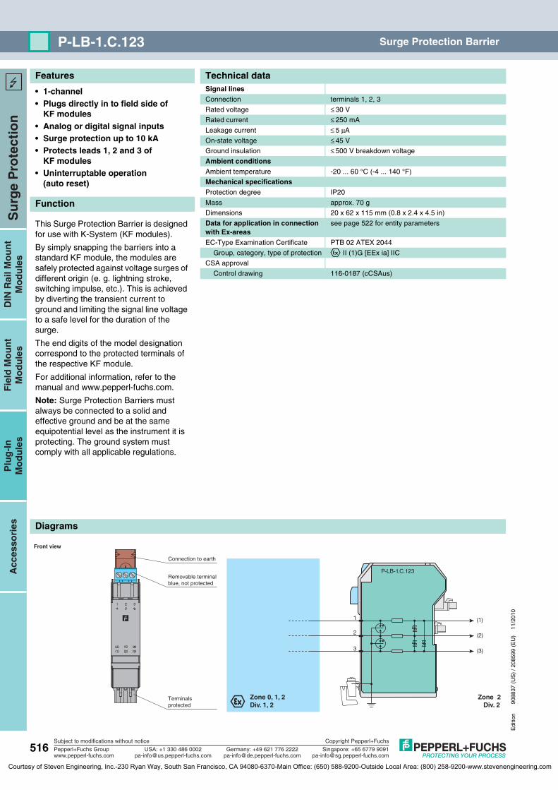
Features
Diagrams
516
Edi
tion
9088
37 (
US
) / 2
0859
9 (E
U)
11/2
010
Su
rge
Pro
tect
ion
Plu
g-I
nM
od
ule
sD
IN R
ail M
ou
nt
Mo
du
les
Fie
ld M
ou
nt
Mo
du
les
Acc
esso
ries
Subject to modifications without notice
Pepperl+Fuchs Groupwww.pepperl-fuchs.com
USA: +1 330 486 [email protected] [email protected]
Singapore: +65 6779 [email protected]
Copyright Pepperl+Fuchs
Germany: +49 621 776 2222
P-LB-1.C.123 Surge Protection Barrier
• 1-channel• Plugs directly in to field side of
KF modules• Analog or digital signal inputs• Surge protection up to 10 kA• Protects leads 1, 2 and 3 of
KF modules• Uninterruptable operation
(auto reset)
Function
This Surge Protection Barrier is designed for use with K-System (KF modules).
By simply snapping the barriers into a standard KF module, the modules are safely protected against voltage surges of different origin (e. g. lightning stroke, switching impulse, etc.). This is achieved by diverting the transient current to ground and limiting the signal line voltage to a safe level for the duration of the surge.
The end digits of the model designation correspond to the protected terminals of the respective KF module.
For additional information, refer to the manual and www.pepperl-fuchs.com.
Note: Surge Protection Barriers must always be connected to a solid and effective ground and be at the same equipotential level as the instrument it is protecting. The ground system must comply with all applicable regulations.
Technical dataSignal linesConnection terminals 1, 2, 3
Rated voltage ≤ 30 V
Rated current ≤ 250 mA
Leakage current ≤ 5 μA
On-state voltage ≤ 45 V
Ground insulation ≤ 500 V breakdown voltage
Ambient conditionsAmbient temperature -20 ... 60 °C (-4 ... 140 °F)
Mechanical specificationsProtection degree IP20
Mass approx. 70 g
Dimensions 20 x 62 x 115 mm (0.8 x 2.4 x 4.5 in)
Data for application in connection with Ex-areas
see page 522 for entity parameters
EC-Type Examination Certificate PTB 02 ATEX 2044
Group, category, type of protection ¬ II (1)G [EEx ia] IIC
CSA approval
Control drawing 116-0187 (cCSAus)
P-LB-1.C.123
Zone 2Div. 2
Zone 0, 1, 2Div. 1, 2
(2)
(3)
(1)
2
1
3
Front view
Removable terminalblue, not protected
Connection to earth
Terminalsprotected
P-LB-1.C.123
Courtesy of Steven Engineering, Inc.-230 Ryan Way, South San Francisco, CA 94080-6370-Main Office: (650) 588-9200-Outside Local Area: (800) 258-9200-www.stevenengineering.com

Features
Diagrams
Edi
tion
9088
37 (
US
) / 2
0859
9 (E
U)
11/2
010
517
Su
rge
Pro
tect
ion
Plu
g-I
nM
od
ule
sD
IN R
ail M
ou
nt
Mo
du
les
Fie
ld M
ou
nt
Mo
du
les
Acc
esso
ries
Subject to modifications without notice
Pepperl+Fuchs Groupwww.pepperl-fuchs.com
USA: +1 330 486 [email protected] [email protected]
Singapore: +65 6779 [email protected]
Copyright Pepperl+Fuchs
Germany: +49 621 776 2222
P-LB-2.D.123456Surge Protection Barrier
• 2-channel• Plugs directly in to field side of
KF modules• Analog or digital signal inputs• Surge protection up to 10 kA• Protects leads 1, 2, 3, 4, 5 and 6 of
KF modules• Uninterruptable operation
(auto reset)
Function
This Surge Protection Barrier is designed for use with K-System (KF modules).
By simply snapping the barriers into a standard KF module, the modules are safely protected against voltage surges of different origin (e. g. lightning stroke, switching impulse, etc.). This is achieved by diverting the transient current to ground and limiting the signal line voltage to a safe level for the duration of the surge.
The end digits of the model designation correspond to the protected terminals of the respective KF module.
For additional information, refer to the manual and www.pepperl-fuchs.com.
Note: Surge Protection Barriers must always be connected to a solid and effective ground and be at the same equipotential level as the instrument it is protecting. The ground system must comply with all applicable regulations.
Technical dataSignal linesConnection terminals 1, 2, 3; 4, 5, 6
Rated voltage ≤ 30 V
Rated current ≤ 250 mA
Leakage current ≤ 5 μA
On-state voltage ≤ 45 V
Ground insulation ≤ 500 V breakdown voltage
Ambient conditionsAmbient temperature -20 ... 60 °C (-4 ... 140 °F)
Mechanical specificationsProtection degree IP20
Mass approx. 70 g
Dimensions 20 x 62 x 115 mm (0.8 x 2.4 x 4.5 in)
Data for application in connection with Ex-areas
see page 522 for entity parameters
EC-Type Examination Certificate PTB 02 ATEX 2044
Group, category, type of protection ¬ II (1)G [EEx ia] IIC
CSA approval
Control drawing 116-0187 (cCSAus)
P-LB-2.D.123456
Zone 2Div. 2
Zone 0, 1, 2Div. 1, 2
(2)
(3)
(1)
(5)
(6)
(4)
2
1
3
5
4
6
Front view
Removable terminalsblue, not protected
Connection to earth
Terminalsprotected
P-LB-
2.D.12345
Courtesy of Steven Engineering, Inc.-230 Ryan Way, South San Francisco, CA 94080-6370-Main Office: (650) 588-9200-Outside Local Area: (800) 258-9200-www.stevenengineering.com

Features
Diagrams
518
Edi
tion
9088
37 (
US
) / 2
0859
9 (E
U)
11/2
010
Su
rge
Pro
tect
ion
Plu
g-I
nM
od
ule
sD
IN R
ail M
ou
nt
Mo
du
les
Fie
ld M
ou
nt
Mo
du
les
Acc
esso
ries
Subject to modifications without notice
Pepperl+Fuchs Groupwww.pepperl-fuchs.com
USA: +1 330 486 [email protected] [email protected]
Singapore: +65 6779 [email protected]
Copyright Pepperl+Fuchs
Germany: +49 621 776 2222
P-LB-1.E.23 Surge Protection Barrier
• 1-channel• Plugs directly in to field side of
KF modules• Analog or digital signal inputs• Surge protection up to 10 kA• Protects leads 2 and 3 of KF modules• Uninterruptable operation
(auto reset)
Function
This Surge Protection Barrier is designed for use with K-System (KF modules).
By simply snapping the barriers into a standard KF module, the modules are safely protected against voltage surges of different origin (e. g. lightning stroke, switching impulse, etc.). This is achieved by diverting the transient current to ground and limiting the signal line voltage to a safe level for the duration of the surge.
The end digits of the model designation correspond to the protected terminals of the respective KF module.
For additional information, refer to the manual and www.pepperl-fuchs.com.
Note: Surge Protection Barriers must always be connected to a solid and effective ground and be at the same equipotential level as the instrument it is protecting. The ground system must comply with all applicable regulations.
Technical dataSignal linesConnection terminals 2, 3
Rated voltage ≤ 30 V
Rated current ≤ 250 mA
Leakage current ≤ 5 μA
On-state voltage ≤ 45 V
Ground insulation ≤ 500 V breakdown voltage
Ambient conditionsAmbient temperature -20 ... 60 °C (-4 ... 140 °F)
Mechanical specificationsProtection degree IP20
Mass approx. 70 g
Dimensions 20 x 62 x 115 mm (0.8 x 2.4 x 4.5 in)
Data for application in connection with Ex-areas
see page 522 for entity parameters
EC-Type Examination Certificate PTB 02 ATEX 2044
Group, category, type of protection ¬ II (1)G [EEx ia] IIC
CSA approval
Control drawing 116-0187 (cCSAus)
P-LB-1.E.23
Zone 2Div. 2
Zone 0, 1, 2Div. 1, 2
(2)
(3)
2
3
Front view
Removable terminalblue, not protected
Connection to earth
Terminalsprotected
P-LB-1.E.23
Courtesy of Steven Engineering, Inc.-230 Ryan Way, South San Francisco, CA 94080-6370-Main Office: (650) 588-9200-Outside Local Area: (800) 258-9200-www.stevenengineering.com
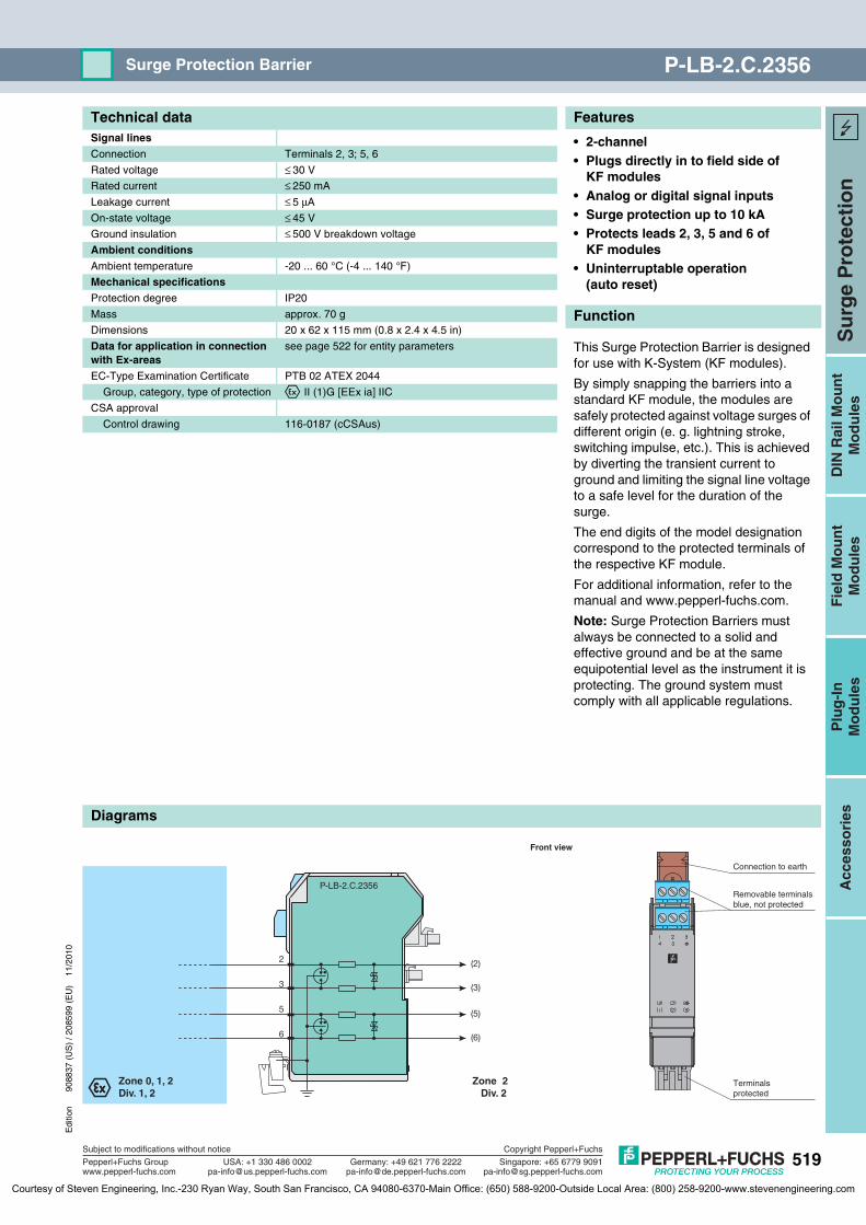
Features
Diagrams
Edi
tion
9088
37 (
US
) / 2
0859
9 (E
U)
11/2
010
519
Su
rge
Pro
tect
ion
Plu
g-I
nM
od
ule
sD
IN R
ail M
ou
nt
Mo
du
les
Fie
ld M
ou
nt
Mo
du
les
Acc
esso
ries
Subject to modifications without notice
Pepperl+Fuchs Groupwww.pepperl-fuchs.com
USA: +1 330 486 [email protected] [email protected]
Singapore: +65 6779 [email protected]
Copyright Pepperl+Fuchs
Germany: +49 621 776 2222
P-LB-2.C.2356Surge Protection Barrier
• 2-channel• Plugs directly in to field side of
KF modules• Analog or digital signal inputs• Surge protection up to 10 kA• Protects leads 2, 3, 5 and 6 of
KF modules• Uninterruptable operation
(auto reset)
Function
This Surge Protection Barrier is designed for use with K-System (KF modules).
By simply snapping the barriers into a standard KF module, the modules are safely protected against voltage surges of different origin (e. g. lightning stroke, switching impulse, etc.). This is achieved by diverting the transient current to ground and limiting the signal line voltage to a safe level for the duration of the surge.
The end digits of the model designation correspond to the protected terminals of the respective KF module.
For additional information, refer to the manual and www.pepperl-fuchs.com.
Note: Surge Protection Barriers must always be connected to a solid and effective ground and be at the same equipotential level as the instrument it is protecting. The ground system must comply with all applicable regulations.
Technical dataSignal linesConnection Terminals 2, 3; 5, 6
Rated voltage ≤ 30 V
Rated current ≤ 250 mA
Leakage current ≤ 5 μA
On-state voltage ≤ 45 V
Ground insulation ≤ 500 V breakdown voltage
Ambient conditionsAmbient temperature -20 ... 60 °C (-4 ... 140 °F)
Mechanical specificationsProtection degree IP20
Mass approx. 70 g
Dimensions 20 x 62 x 115 mm (0.8 x 2.4 x 4.5 in)
Data for application in connection with Ex-areas
see page 522 for entity parameters
EC-Type Examination Certificate PTB 02 ATEX 2044
Group, category, type of protection ¬ II (1)G [EEx ia] IIC
CSA approval
Control drawing 116-0187 (cCSAus)
P-LB-2.C.2356
Zone 2Div. 2
Zone 0, 1, 2Div. 1, 2
(2)
(3)
(5)
(6)
2
3
5
6
Front view
Removable terminalsblue, not protected
Connection to earth
Terminalsprotected
P-LB-2.C.2356
Courtesy of Steven Engineering, Inc.-230 Ryan Way, South San Francisco, CA 94080-6370-Main Office: (650) 588-9200-Outside Local Area: (800) 258-9200-www.stevenengineering.com

Features
Diagrams
520
Edi
tion
9088
37 (
US
) / 2
0859
9 (E
U)
11/2
010
Su
rge
Pro
tect
ion
Plu
g-I
nM
od
ule
sD
IN R
ail M
ou
nt
Mo
du
les
Fie
ld M
ou
nt
Mo
du
les
Acc
esso
ries
Subject to modifications without notice
Pepperl+Fuchs Groupwww.pepperl-fuchs.com
USA: +1 330 486 [email protected] [email protected]
Singapore: +65 6779 [email protected]
Copyright Pepperl+Fuchs
Germany: +49 621 776 2222
P-LB-1.D.1234 Surge Protection Barrier
• 1-channel• Plugs directly in to field side of
KF modules• Analog or digital signal inputs• Surge protection up to 10 kA• Protects leads 1, 2, 3 and 4 of
KF modules• Uninterruptable operation
(auto reset)
Function
This Surge Protection Barrier is designed for use with K-System (KF modules).
By simply snapping the barriers into a standard KF module, the modules are safely protected against voltage surges of different origin (e. g. lightning stroke, switching impulse, etc.). This is achieved by diverting the transient current to ground and limiting the signal line voltage to a safe level for the duration of the surge.
The end digits of the model designation correspond to the protected terminals of the respective KF module.
For additional information, refer to the manual and www.pepperl-fuchs.com.
Note: Surge Protection Barriers must always be connected to a solid and effective ground and be at the same equipotential level as the instrument it is protecting. The ground system must comply with all applicable regulations.
Technical dataSignal linesConnection terminals 1, 2, 3, 4
Rated voltage ≤ 30 V
Rated current ≤ 250 mA
Leakage current ≤ 5 μA
On-state voltage ≤ 45 V
Ground insulation ≤ 500 V breakdown voltage
Ambient conditionsAmbient temperature -20 ... 60 °C (-4 ... 140 °F)
Mechanical specificationsProtection degree IP20
Mass approx. 70 g
Dimensions 20 x 62 x 115 mm (0.8 x 2.4 x 4.5 in)
Data for application in connection with Ex-areas
see page 522 for entity parameters
EC-Type Examination Certificate PTB 02 ATEX 2044
Group, category, type of protection ¬ II (1)G [EEx ia] IIC
CSA approval
Control drawing 116-0187 (cCSAus)
P-LB-1.D.1234
Zone 2Div. 2
Zone 0, 1, 2Div. 1, 2
(1)
(2)
(3)
(4)
1
2
3
4
Front view
Removable terminalblue, not protected
Connection to earth
Terminalsprotected
P-LB-1.D.1234
Courtesy of Steven Engineering, Inc.-230 Ryan Way, South San Francisco, CA 94080-6370-Main Office: (650) 588-9200-Outside Local Area: (800) 258-9200-www.stevenengineering.com

Features
Diagrams
Edi
tion
9088
37 (
US
) / 2
0859
9 (E
U)
11/2
010
521
Su
rge
Pro
tect
ion
Plu
g-I
nM
od
ule
sD
IN R
ail M
ou
nt
Mo
du
les
Fie
ld M
ou
nt
Mo
du
les
Acc
esso
ries
Subject to modifications without notice
Pepperl+Fuchs Groupwww.pepperl-fuchs.com
USA: +1 330 486 [email protected] [email protected]
Singapore: +65 6779 [email protected]
Copyright Pepperl+Fuchs
Germany: +49 621 776 2222
P-LB-1.F.1236Surge Protection Barrier
• 1-channel• Plugs directly in to field side of
KF modules• Analog or digital signal inputs• Surge protection up to 10 kA• Protects leads 1, 2, 3 and 6 of
KF modules• Uninterruptable operation
(auto reset)
Function
This Surge Protection Barrier is designed for use with K-System (KF modules).
By simply snapping the barriers into a standard KF module, the modules are safely protected against voltage surges of different origin (e. g. lightning stroke, switching impulse, etc.). This is achieved by diverting the transient current to ground and limiting the signal line voltage to a safe level for the duration of the surge.
The end digits of the model designation correspond to the protected terminals of the respective KF module.
For additional information, refer to the manual and www.pepperl-fuchs.com.
Note: Surge Protection Barriers must always be connected to a solid and effective ground and be at the same equipotential level as the instrument it is protecting. The ground system must comply with all applicable regulations.
Technical dataSignal linesConnection terminals 1, 2, 3, 6
Rated voltage ≤ 30 V
Rated current ≤ 250 mA
Leakage current ≤ 5 μA
On-state voltage ≤ 45 V
Ground insulation ≤ 500 V breakdown voltage
Ambient conditionsAmbient temperature -20 ... 60 °C (-4 ... 140 °F)
Mechanical specificationsProtection degree IP20
Mass approx. 70 g
Dimensions 20 x 62 x 115 mm (0.8 x 2.4 x 4.5 in)
Data for application in connection with Ex-areas
see page 522 for entity parameters
EC-Type Examination Certificate PTB 02 ATEX 2044
Group, category, type of protection ¬ II (1)G [EEx ia] IIC
CSA approval
Control drawing 116-0187 (cCSAus)
P-LB-1.F.1236
Zone 2Div. 2
Zone 0, 1, 2Div. 1, 2
(1)
(2)
(3)
(6)
1
2
3
6
Front view
Removable terminalblue, not protected
Connection to earth
Terminalsprotected
P-LB-1.F.1236
Courtesy of Steven Engineering, Inc.-230 Ryan Way, South San Francisco, CA 94080-6370-Main Office: (650) 588-9200-Outside Local Area: (800) 258-9200-www.stevenengineering.com
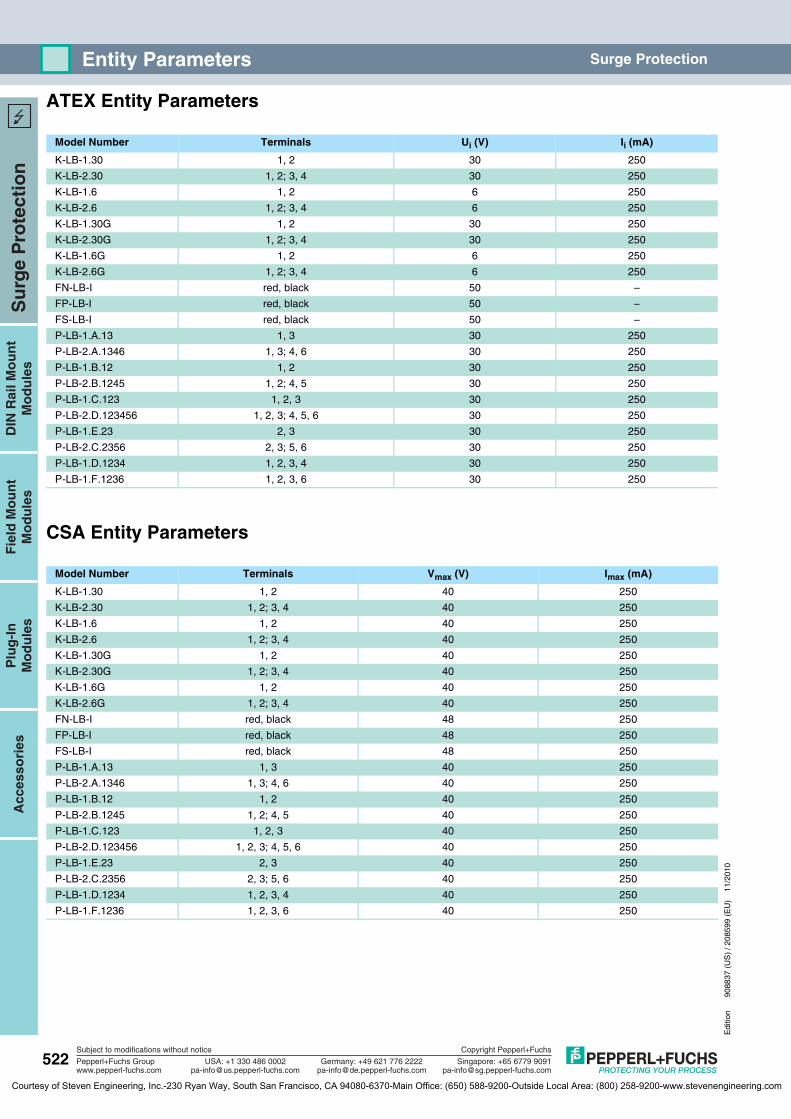
522
Edi
tion
9088
37 (
US
) / 2
0859
9 (E
U)
11/2
010
Su
rge
Pro
tect
ion
Plu
g-I
nM
od
ule
sA
cces
sori
esD
IN R
ail M
ou
nt
Mo
du
les
Fie
ld M
ou
nt
Mo
du
les
Subject to modifications without notice
Pepperl+Fuchs Groupwww.pepperl-fuchs.com
USA: +1 330 486 [email protected] [email protected]
Singapore: +65 6779 [email protected]
Copyright Pepperl+Fuchs
Germany: +49 621 776 2222
Entity Parameters Surge Protection
ATEX Entity Parameters
CSA Entity Parameters
Model Number Terminals Ui (V) Ii (mA)
K-LB-1.30 1, 2 30 250
K-LB-2.30 1, 2; 3, 4 30 250
K-LB-1.6 1, 2 6 250
K-LB-2.6 1, 2; 3, 4 6 250
K-LB-1.30G 1, 2 30 250
K-LB-2.30G 1, 2; 3, 4 30 250
K-LB-1.6G 1, 2 6 250
K-LB-2.6G 1, 2; 3, 4 6 250
FN-LB-I red, black 50 –
FP-LB-I red, black 50 –
FS-LB-I red, black 50 –
P-LB-1.A.13 1, 3 30 250
P-LB-2.A.1346 1, 3; 4, 6 30 250
P-LB-1.B.12 1, 2 30 250
P-LB-2.B.1245 1, 2; 4, 5 30 250
P-LB-1.C.123 1, 2, 3 30 250
P-LB-2.D.123456 1, 2, 3; 4, 5, 6 30 250
P-LB-1.E.23 2, 3 30 250
P-LB-2.C.2356 2, 3; 5, 6 30 250
P-LB-1.D.1234 1, 2, 3, 4 30 250
P-LB-1.F.1236 1, 2, 3, 6 30 250
Model Number Terminals Vmax (V) Imax (mA)
K-LB-1.30 1, 2 40 250
K-LB-2.30 1, 2; 3, 4 40 250
K-LB-1.6 1, 2 40 250
K-LB-2.6 1, 2; 3, 4 40 250
K-LB-1.30G 1, 2 40 250
K-LB-2.30G 1, 2; 3, 4 40 250
K-LB-1.6G 1, 2 40 250
K-LB-2.6G 1, 2; 3, 4 40 250
FN-LB-I red, black 48 250
FP-LB-I red, black 48 250
FS-LB-I red, black 48 250
P-LB-1.A.13 1, 3 40 250
P-LB-2.A.1346 1, 3; 4, 6 40 250
P-LB-1.B.12 1, 2 40 250
P-LB-2.B.1245 1, 2; 4, 5 40 250
P-LB-1.C.123 1, 2, 3 40 250
P-LB-2.D.123456 1, 2, 3; 4, 5, 6 40 250
P-LB-1.E.23 2, 3 40 250
P-LB-2.C.2356 2, 3; 5, 6 40 250
P-LB-1.D.1234 1, 2, 3, 4 40 250
P-LB-1.F.1236 1, 2, 3, 6 40 250
Courtesy of Steven Engineering, Inc.-230 Ryan Way, South San Francisco, CA 94080-6370-Main Office: (650) 588-9200-Outside Local Area: (800) 258-9200-www.stevenengineering.com
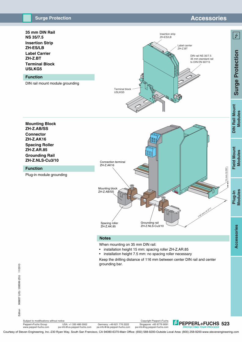
Edi
tion
9088
37 (
US
) / 2
0859
9 (E
U)
11/2
010
523
Su
rge
Pro
tect
ion
Plu
g-I
nM
od
ule
sD
IN R
ail M
ou
nt
Mo
du
les
Fie
ld M
ou
nt
Mo
du
les
Acc
esso
ries
Subject to modifications without notice
Pepperl+Fuchs Groupwww.pepperl-fuchs.com
USA: +1 330 486 [email protected] [email protected]
Singapore: +65 6779 [email protected]
Copyright Pepperl+Fuchs
Germany: +49 621 776 2222
AccessoriesSurge Protection
35 mm DIN RailNS 35/7.5Insertion StripZH-ES/LBLabel CarrierZH-Z.BTTerminal BlockUSLKG5
DIN rail mount module grounding
Mounting BlockZH-Z.AB/SSConnectorZH-Z.AK16Spacing RollerZH-Z.AR.85Grounding RailZH-Z.NLS-Cu3/10
Plug-in module grounding
When mounting on 35 mm DIN rail:• installation height 15 mm: spacing roller ZH-Z.AR.85• installation height 7.5 mm: no spacing roller necessary
Keep the drilling distance of 116 mm between center DIN rail and center grounding bar.
Function
Insertion stripZH-ES/LB
Terminal blockUSLKG5
Label carrierZH-Z.BT
DIN rail NS 35/7.535 mm standard railto DIN EN 60715
Function
116 mm (4
.57'')
15 m
m (
0.59
'')
1
2
3 4
Mounting blockZH-Z.AB/SS
Connection terminalZH-Z.AK16
Spacing rollerZH-Z.AK.85
Grounding railZH-Z.NLS-Cu3/10
Notes
Courtesy of Steven Engineering, Inc.-230 Ryan Way, South San Francisco, CA 94080-6370-Main Office: (650) 588-9200-Outside Local Area: (800) 258-9200-www.stevenengineering.com