Embed Size (px)
Citation preview
PeopleNet Installation Manual The PeopleNet Installation Manual provides step by step instructions for installing PeopleNet
Onboard Computer systems in vehicles.
Version 1.2 2/9/2012
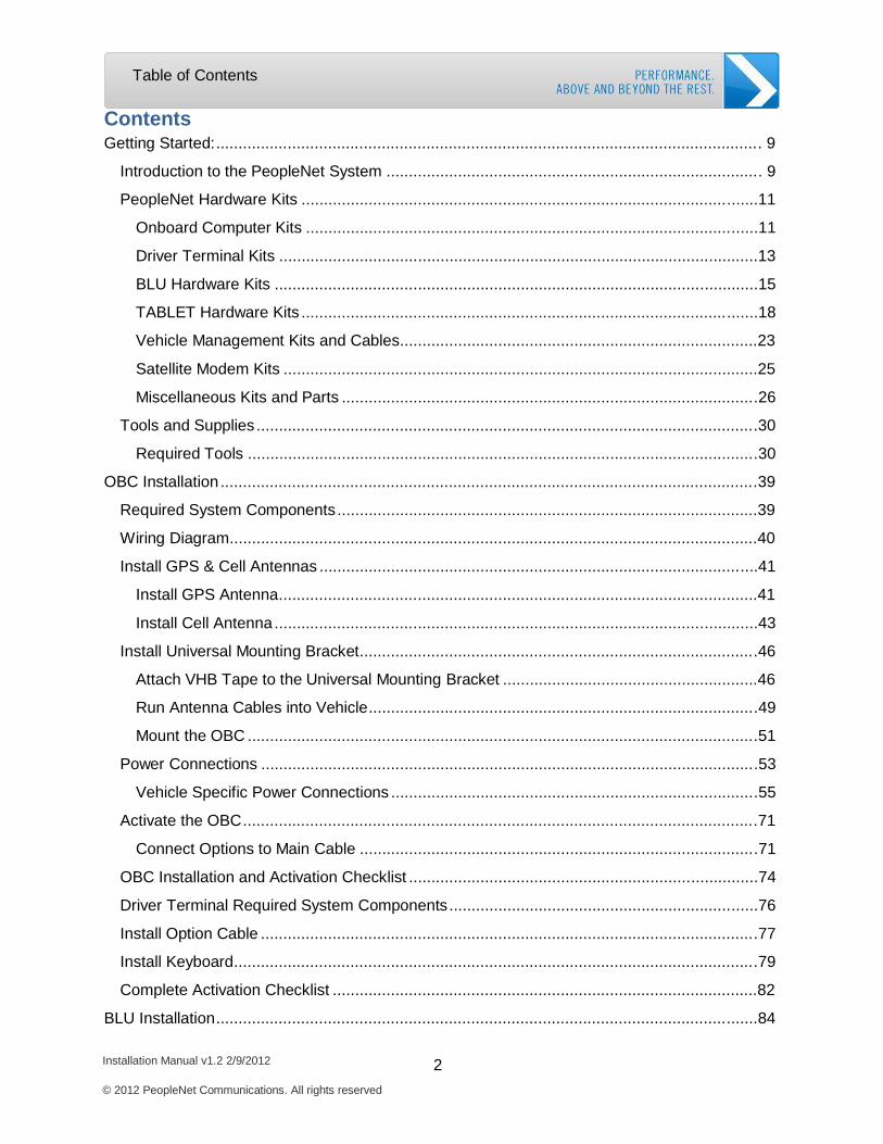
Table of Contents
Installation Manual v1.2 2/9/2012 2 © 2012 PeopleNet Communications. All rights reserved
Contents Getting Started: .......................................................................................................................... 9
Introduction to the PeopleNet System .................................................................................... 9
PeopleNet Hardware Kits ......................................................................................................11
Onboard Computer Kits .....................................................................................................11
Driver Terminal Kits ...........................................................................................................13
BLU Hardware Kits ............................................................................................................15
TABLET Hardware Kits ......................................................................................................18
Vehicle Management Kits and Cables................................................................................23
Satellite Modem Kits ..........................................................................................................25
Miscellaneous Kits and Parts .............................................................................................26
Tools and Supplies ................................................................................................................30
Required Tools ..................................................................................................................30
OBC Installation ........................................................................................................................39
Required System Components ..............................................................................................39
Wiring Diagram......................................................................................................................40
Install GPS & Cell Antennas ..................................................................................................41
Install GPS Antenna...........................................................................................................41
Install Cell Antenna ............................................................................................................43
Install Universal Mounting Bracket.........................................................................................46
Attach VHB Tape to the Universal Mounting Bracket .........................................................46
Run Antenna Cables into Vehicle.......................................................................................49
Mount the OBC ..................................................................................................................51
Power Connections ...............................................................................................................53
Vehicle Specific Power Connections ..................................................................................55
Activate the OBC ...................................................................................................................71
Connect Options to Main Cable .........................................................................................71
OBC Installation and Activation Checklist ..............................................................................74
Driver Terminal Required System Components .....................................................................76
Install Option Cable ...............................................................................................................77
Install Keyboard.....................................................................................................................79
Complete Activation Checklist ...............................................................................................82
BLU Installation.........................................................................................................................84
Table of Contents
Installation Manual v1.2 2/9/2012 3 © 2012 PeopleNet Communications. All rights reserved
BLU Required System Components ......................................................................................84
Mount BLU ............................................................................................................................85
Install DC to DC Converter ....................................................................................................87
Connect the DC to DC Power Converter to the PeopleNet System ....................................87
Connect the DC to DC Converter to Power ........................................................................88
Install External Speaker.........................................................................................................90
Complete BLU Installation Checklist ......................................................................................94
TABLET Installation ..................................................................................................................96
Mount the Docking Station.....................................................................................................97
Connect the DC to DC Converter to the PeopleNet System ...............................................98
Mount the DC to DC Converter ..........................................................................................98
Connect Power to DC to DC Power Converter ...................................................................99
Plug in TABLET Dock, Keyboard, Speaker ......................................................................100
OBC Firmware Download ....................................................................................................103
Complete TABLET Activation ..............................................................................................104
Complete TABLET Activation Checklist ...............................................................................105
BLU.2 Installation ....................................................................................................................107
Required System Components ............................................................................................107
Mount BLU.2 .......................................................................................................................108
Install Keyboard ...............................................................................................................108
Install DC to DC Converter ..................................................................................................109
Mount the DC to DC Connector .......................................................................................110
Connect OBC to BLU.2 ....................................................................................................110
OBC Firmware Download ....................................................................................................112
Complete BLU.2 Activation ..................................................................................................113
Complete Activation Checklist .............................................................................................114
Vehicle Management Installation ............................................................................................116
Required System Components ............................................................................................116
Install J1708 Vehicle Management ......................................................................................118
Install the Universal Vehicle Management Cable .............................................................118
Install the Packard 2-Pin Vehicle Management Cable ......................................................118
Install Multi-bus Adapter ......................................................................................................120
Install Multi-Bus Adapter with Repeater/9 Pin Cable ........................................................120
Table of Contents
Installation Manual v1.2 2/9/2012 4 © 2012 PeopleNet Communications. All rights reserved
Install Multi-Bus Adapter with Pigtails...............................................................................121
PTO Connections.............................................................................................................124
Activate Multi-Bus Adapter ...............................................................................................125
Functional Test ................................................................................................................126
OBD-II Installation Instructions .........................................................................................127
Activate OBD-II ................................................................................................................128
Functional Test ................................................................................................................128
Complete Vehicle Management Checklist ...........................................................................130
Driver Terminal Checklist .................................................................................................130
BLU, BLU.2, and TABLET Checklist ................................................................................131
Satellite Modem Installation ....................................................................................................133
Required System Components ............................................................................................133
Mount Satellite Antenna ......................................................................................................134
Mount Satellite Modem ........................................................................................................135
Activate the Satellite Modem ...............................................................................................136
Activate Satellite for Driver Terminal ................................................................................136
Activate Satellite for BLU, BLU.2, and TABLET ...............................................................136
Installation Manual v1.2 2/9/2012 5 © 2012 PeopleNet Communications. All rights reserved
Table of Figures
Table of Figures
Table 1: OBC Kit .......................................................................................................................11 Table 2: OBC installation Kit .....................................................................................................11 Table 3: Driver Terminal Display ...............................................................................................13 Table 4: Keyboard Kit................................................................................................................14 Table 5: Keyboard Bracket........................................................................................................14 Table 6: BLU Display Kit ...........................................................................................................15 Table 7: BLU Installation Kit ......................................................................................................15 Table 8: DC/DC Converter ........................................................................................................16 Table 9: BLU Keyboard.............................................................................................................17 Table 10: BLU Pedestal Mount .................................................................................................17 Table 11: BLU.2 Kit ...................................................................................................................18 Table 12: BLU.2 Installation Kit .................................................................................................18 Table 13: Standard TABLET .....................................................................................................20 Table 14: Premium TABLET .....................................................................................................20 Table 15: TABLET Installation Kit..............................................................................................21 Table 16: TABLET Speaker Kit .................................................................................................22 Table 17: Multi-Bus Adapter Kit.................................................................................................23 Table 18: Multi-Bus Adapter with Repeater/Jumper Kit .............................................................24 Table 19: Universal Vehicle Management Cable.......................................................................25 Table 20: Packard 2-Pin Vehicle Management Cable ...............................................................25 Table 21: Satellite Modem Kit ...................................................................................................25 Table 22: Satellite Modem Installation Kit..................................................................................25 Table 23: Tech Kit .....................................................................................................................26 Figure 1: Appropriate mounting area for Driver Terminal...........................................................32 Figure 2: Appropriate mounting area for BLU/BLU2 ..................................................................33 Figure 3: Appropriate mounting area for TABLET .....................................................................33 Figure 4: Properly taped connections ........................................................................................34 Figure 5: Safe OBC install location for sleeper berth vehicles ...................................................34 Figure 6: Safe OBC install location for day cab vehicles ...........................................................34 Figure 10: Properly Routed and Secured Antennas ..................................................................35 Figure 12: VHB Tape and Alcohol Pads ....................................................................................36 Figure 13: Secure ground .........................................................................................................37 Figure 14: Required System Components.................................................................................39 Figure 15: Wiring Diagram ........................................................................................................40 Figure 16: VHB Tape on GPS Antenna .....................................................................................41 Figure 17: Area to Clean on the Universal Mounting Bracket ....................................................42 Figure 18: GPS Antenna Mounted on Universal Mounting Bracket ...........................................42 Figure 19: Cell Antenna Parts ...................................................................................................43 Figure 20: Assembly Order of Cell Antenna (assemble right to left) ..........................................44 Figure 21: Antennas Installed on the Universal Mounting Bracket.............................................44
Installation Manual v1.2 2/9/2012 6 © 2012 PeopleNet Communications. All rights reserved
Table of Figures
Figure 21: Universal Mounting Bracket Mounted on Vehicle .....................................................46 Figure 22: Tape Placement on Universal Mounting Bracket ......................................................46 Figure 23: Three Hole Grommet and Antenna Cables...............................................................49 Figure 24: Cables Secured to Vehicle .......................................................................................50 Figure 25: OBC with Self-Tapping Screws ................................................................................51 Figure 26: Connect Main Cable to OBC ....................................................................................52 Figure 27: Power Connection/Fuse Assembly...........................................................................53 Figure 28: Butt Connectors .......................................................................................................54 Figure 29: Harness Spare Connector ........................................................................................60 Figure 30: Options Cable ..........................................................................................................71 Figure 31: OBC Diagnostic Information Screen.........................................................................72 Figure 32: Home Menu on Display ............................................................................................72 Figure 33: Display Upon Receiving Message ............................................................................73 Figure 34: Option Cable Connections .......................................................................................77 Figure 35: Cable Tied to Swivel Mount Ball Joint ......................................................................78 Figure 36: Ziptied Keyboard Cable for Strain Relief ..................................................................79 Figure 37: Home Menu on Display ............................................................................................80 Figure 38: Display Upon Receiving Message ............................................................................80 Figure 39: BLU Mounting Location Example .............................................................................85 Figure 40: Mounted BLU Bracket ..............................................................................................85 Figure 41: Connect Main Cable blue Connector and BLU Options Cable Connector to DC to DC Converter ..................................................................................................................................87 Figure 42: Example of Correct DC to DC Converter Mount .......................................................88 Figure 43: DC to DC Power Connections ..................................................................................88 Table 24: DC to DC Converter Wire Descriptions......................................................................89 Figure 44: Connect BLU to Options Cable ................................................................................89 Figure 45: Keyboard USB Connector with Electrical Tape and Zip Tie ......................................89 Figure 46: External Speaker......................................................................................................90 Figure 47: Speaker Power Wire ................................................................................................90 Figure 48: Power Wire and Ground Wire with a Ring Connector ...............................................91 Figure 49: Speaker Mono Plug..................................................................................................91 Figure 50: BLU Speaker Jack ...................................................................................................91 Figure 51: Example of Mounted TABLET and Docking Station .................................................97 Figure 52: DC to DC Converter Connections ............................................................................98 Figure 53: Properly Mounted DC to DC Converter ....................................................................99 Figure 54: DC to DC Power Connections ..................................................................................99 Table 25: DC to DC Converter Wire Colors.............................................................................100 Figure 55: TABLET Dock Connections....................................................................................100 Figure 56: USB Connection Secured with Electrical Tape and Zip Tie ...................................101 Figure 57: TABLET Indicator Lights ........................................................................................101 Figure 58: BLU.2 Installation Kit ..............................................................................................107 Figure 59: BLU.2 Cable Assembly ..........................................................................................108 Figure 60: USB Connection with Electrical Tape and Zip Tie ..................................................108 Figure 61: DC to DC Converter and Connectors .....................................................................109
Installation Manual v1.2 2/9/2012 7 © 2012 PeopleNet Communications. All rights reserved
Table of Figures
Figure 62: Ground and Power Connector................................................................................109 Table 24: DC to DC Power Wires............................................................................................110 Figure 63: BLU 2 Options Cable Connector ............................................................................110 Table 26: Vehicle Management Compatibility Guide ...............................................................116 Figure 64: Connection Box for 2-Pin Vehicle Management Cable ...........................................118 Figure 65: Vehicle to Repeater Cable and 9-Pin Diagnostic Port ............................................120 Figure 66: Keyed Wedge Locks ..............................................................................................121 Figure 67: Terminating Resistor ..............................................................................................121 Figure 68: Remove Wedge Lock .............................................................................................122 Figure 69: Replace Wedge Lock .............................................................................................122 Table 27: J1708 and J1939 Data Bus List ...............................................................................123 Figure 70: Kenworth/Peterbilt J1939 Connector ......................................................................123 Figure 71: PTO Relay Connections .........................................................................................125 Figure 72: OBDII Vehicle Management Kit .............................................................................127 Figure 73: Mounted Satellite Antenna .....................................................................................134 Figure 74: Satellite Antenna Connected to Modem .................................................................134 Figure 75: Satellite Modem with OBC Services Cable and Satellite Antenna ..........................135

Installation Manual v1.2 2/9/2012 8 © 2012 PeopleNet Communications. All rights reserved
1. Getting Started
Introduction to PeopleNet Systems
Hardware Kits
Installation Tools and Supplies
Best Practices for Installation

Getting Started: Introduction to PeopleNet Systems
Installation Manual v1.2 2/9/2012 9 © 2012 PeopleNet Communications. All rights reserved
Getting Started:
Introduction to the PeopleNet System
The PeopleNet System utilizes the satellite Global Positioning System (GPS) to locate and
cellular communication networks to communicate. To accomplish these functions, the system
includes a GPS Antenna, Cellular Antenna, and Onboard Computer (OBC) with a GPS receiver
and cellular modem. These parts form the base of the PeopleNet System.
The GPS Antenna uses signals from three GPS satellites to triangulate the position of the
vehicle within a twenty-foot radius of the actual position. The OBC records the location
information and saves it. Location data is transferred from the OBC to the PeopleNet Data
Center via cellular data calls. During a data call, the cellular modem on the OBC connects to a
cell tower and communicates with the Data Center. PeopleNet then makes the data available
on the PeopleNet Fleet Manager website.
In addition to the base PeopleNet System, PeopleNet has multiple display platforms that
enhance the functionality of the system.
Driver Terminal: A LCD display capable of displaying text messages. PeopleNet BLU®/ PeopleNet BLU.2: A touchscreen display with advanced
applications and in-cab capabilities. PeopleNet TABLET™: An optionally portable touchscreen display with camera and
optional bar code scanner.
Your company may also have purchased additional cables and kits that further enhance the
PeopleNet System. For example, the Vehicle Management Gateway connects to the vehicles

Getting Started: Introduction to PeopleNet Systems
Installation Manual v1.2 2/9/2012 10 © 2012 PeopleNet Communications. All rights reserved
ECM and passes engine data to the OBC. The PeopleNet System can also be expanded to
include scanners and handheld devices.
Installation Manual v1.2 2/9/2012 11 © 2012 PeopleNet Communications. All rights reserved
Getting Started: PeopleNet Hardware Kits
PeopleNet Hardware Kits
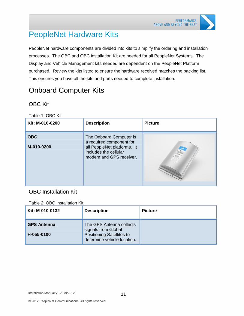
PeopleNet hardware components are divided into kits to simplify the ordering and installation
processes. The OBC and OBC installation Kit are needed for all PeopleNet Systems. The
Display and Vehicle Management kits needed are dependent on the PeopleNet Platform
purchased. Review the kits listed to ensure the hardware received matches the packing list.
This ensures you have all the kits and parts needed to complete installation.
Onboard Computer Kits
OBC Kit
Table 1: OBC Kit
Kit: M-010-0200
Description
Picture
OBC M-010-0200
The Onboard Computer is a required component for all PeopleNet platforms. It includes the cellular modem and GPS receiver.
OBC Installation Kit
Table 2: OBC installation Kit
Kit: M-010-0132
Description
Picture
GPS Antenna H-055-0100
The GPS Antenna collects signals from Global Positioning Satellites to determine vehicle location.
Installation Manual v1.2 2/9/2012 12 © 2012 PeopleNet Communications. All rights reserved
Getting Started: PeopleNet Hardware Kits
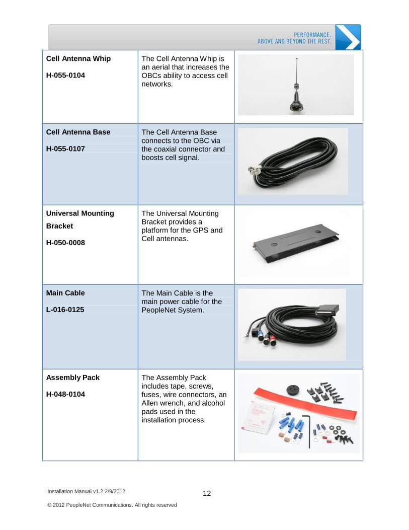
Cell Antenna Whip H-055-0104
The Cell Antenna Whip is an aerial that increases the OBCs ability to access cell networks.
Cell Antenna Base H-055-0107
The Cell Antenna Base connects to the OBC via the coaxial connector and boosts cell signal.
Universal Mounting
Bracket H-050-0008
The Universal Mounting Bracket provides a platform for the GPS and Cell antennas.
Main Cable L-016-0125
The Main Cable is the main power cable for the PeopleNet System.
Assembly Pack H-048-0104
The Assembly Pack includes tape, screws, fuses, wire connectors, an Allen wrench, and alcohol pads used in the installation process.
Installation Manual v1.2 2/9/2012 13 © 2012 PeopleNet Communications. All rights reserved
Getting Started: PeopleNet Hardware Kits
Kit: M-010-0033 Description
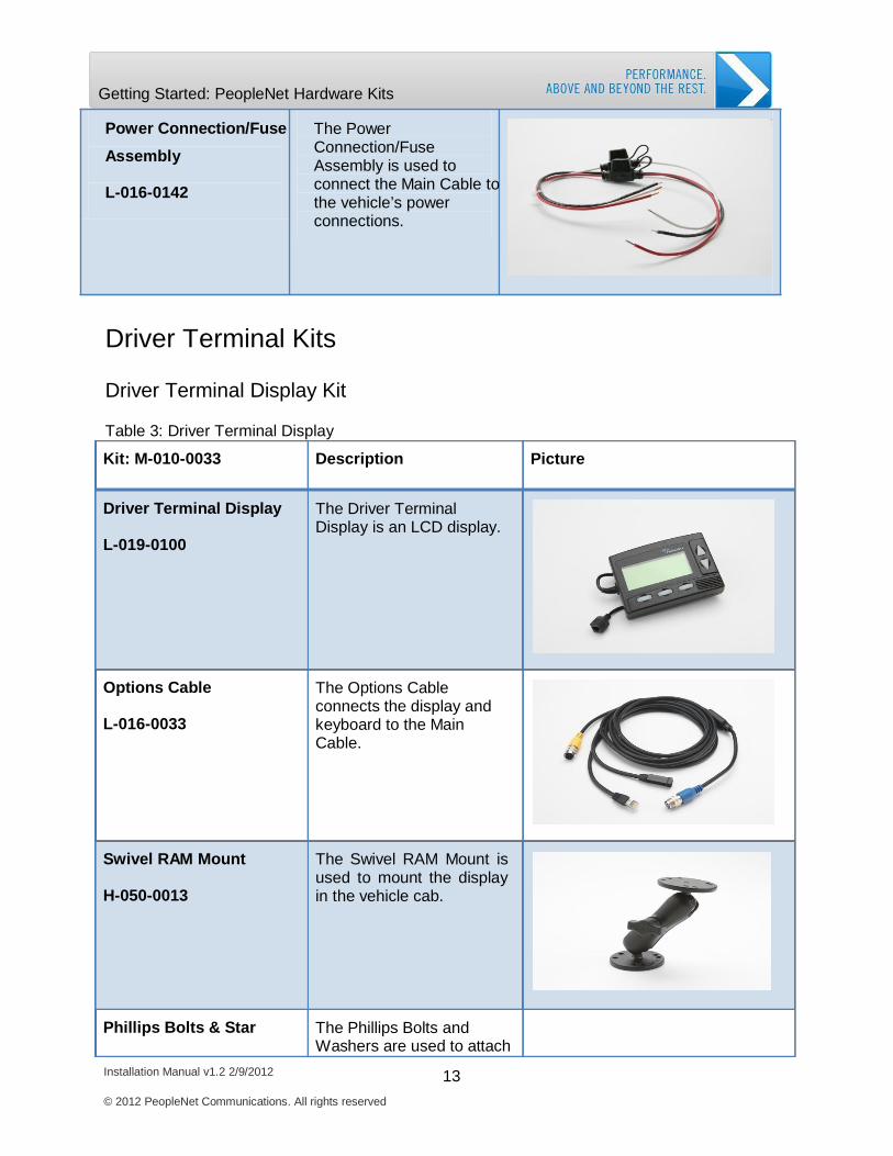
Driver Terminal Display
L-019-0100
The Driver Terminal Display is an LCD display.
Options Cable
L-016-0033
The Options Cable connects the display and keyboard to the Main Cable.
Swivel RAM Mount
H-050-0013
The Swivel RAM Mount is used to mount the display in the vehicle cab.
Phillips Bolts & Star
The Phillips Bolts and Washers are used to attach
Getting Started: PeopleNet Hardware Kits
Power Connection/Fuse
Assembly
L-016-0142
The Power Connection/Fuse Assembly is used to connect the Main Cable to the vehicle’s power connections.
Driver Terminal Kits
Driver Terminal Display Kit
Table 3: Driver Terminal Display Picture
Installation Manual v1.2 2/9/2012 14 © 2012 PeopleNet Communications. All rights reserved
Getting Started: PeopleNet Hardware Kits
Getting Started: PeopleNet Hardware Kits
Washers
H-048-0008
the display to the mount.
Phillips Screw Pack H-048-0001
The Phillips Screw Pack includes screws used to attach the display mount to the dash.
Industrial Strength Velcro L-020-0020
The Velcro can be used to attach the display to the dash without making holes.
Alcohol Wipe F-004-0002
The Alcohol Wipe is used to clean the surfaces where the Velcro will be attached.
Quick Reference Guide
(QRG) D-012-0147
The QRG provides instructions for using the Driver Terminal.
Driver Terminal Keyboard Kit
Table 4: Keyboard Kit
Kit: M-010-0264
Description
Picture
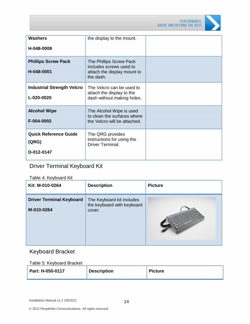
Driver Terminal Keyboard M-010-0264
The Keyboard kit includes the keyboard with keyboard cover.
Keyboard Bracket
Table 5: Keyboard Bracket
Part: H-050-0117 Description Picture
Installation Manual v1.2 2/9/2012 15 © 2012 PeopleNet Communications. All rights reserved
Getting Started: PeopleNet Hardware Kits
Getting Started: PeopleNet Hardware Kits
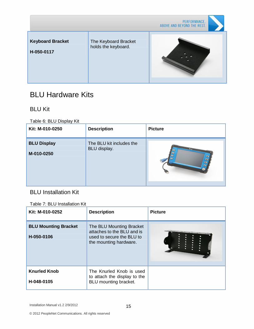
Keyboard Bracket
H-050-0117
The Keyboard Bracket holds the keyboard.
BLU Hardware Kits
BLU Kit
Table 6: BLU Display Kit
Kit: M-010-0250
Description
Picture
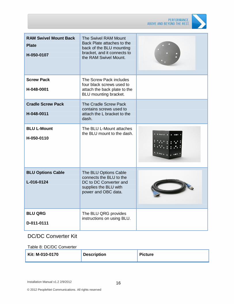
BLU Display M-010-0250
The BLU kit includes the BLU display.
BLU Installation Kit
Table 7: BLU Installation Kit
Kit: M-010-0252
Description
Picture
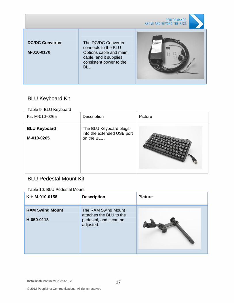
BLU Mounting Bracket H-050-0106
The BLU Mounting Bracket attaches to the BLU and is used to secure the BLU to the mounting hardware.
Knurled Knob H-048-0105
The Knurled Knob is used to attach the display to the BLU mounting bracket.
Installation Manual v1.2 2/9/2012 16 © 2012 PeopleNet Communications. All rights reserved
Getting Started: PeopleNet Hardware Kits
Getting Started: PeopleNet Hardware Kits
RAM Swivel Mount Back
Plate H-050-0107
The Swivel RAM Mount Back Plate attaches to the back of the BLU mounting bracket, and it connects to the RAM Swivel Mount.
Screw Pack H-048-0001
The Screw Pack includes four black screws used to attach the back plate to the BLU mounting bracket.
Cradle Screw Pack H-048-0011
The Cradle Screw Pack contains screws used to attach the L bracket to the dash.
BLU L-Mount H-050-0110
The BLU L-Mount attaches the BLU mount to the dash.
BLU Options Cable L-016-0124
The BLU Options Cable connects the BLU to the DC to DC Converter and supplies the BLU with power and OBC data.
BLU QRG D-011-0111
The BLU QRG provides instructions on using BLU.
DC/DC Converter Kit
Table 8: DC/DC Converter
Kit: M-010-0170 Description Picture
Installation Manual v1.2 2/9/2012 17 © 2012 PeopleNet Communications. All rights reserved
Getting Started: PeopleNet Hardware Kits
Getting Started: PeopleNet Hardware Kits
DC/DC Converter
M-010-0170
The DC/DC Converter connects to the BLU Options cable and main cable, and it supplies consistent power to the BLU.
BLU Keyboard Kit
Table 9: BLU Keyboard
Kit: M-010-0265
Description
Picture
BLU Keyboard M-010-0265
The BLU Keyboard plugs into the extended USB port on the BLU.
BLU Pedestal Mount Kit
Table 10: BLU Pedestal Mount
Kit: M-010-0158
Description
Picture
RAM Swing Mount H-050-0113
The RAM Swing Mount attaches the BLU to the pedestal, and it can be adjusted.
Installation Manual v1.2 2/9/2012 18 © 2012 PeopleNet Communications. All rights reserved
Getting Started: PeopleNet Hardware Kits
Getting Started: PeopleNet Hardware Kits
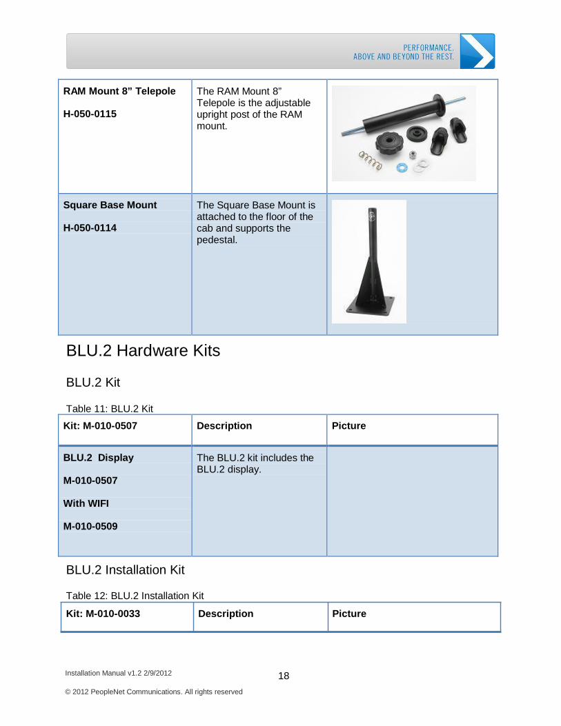
RAM Mount 8” Telepole H-050-0115
The RAM Mount 8” Telepole is the adjustable upright post of the RAM mount.
Square Base Mount H-050-0114
The Square Base Mount is attached to the floor of the cab and supports the pedestal.
BLU.2 Hardware Kits
BLU.2 Kit
Table 11: BLU.2 Kit
Kit: M-010-0507
Description
Picture
BLU.2 Display M-010-0507
With WIFI
M-010-0509
The BLU.2 kit includes the BLU.2 display.
BLU.2 Installation Kit
Table 12: BLU.2 Installation Kit
Kit: M-010-0033 Description Picture
Installation Manual v1.2 2/9/2012 19 © 2012 PeopleNet Communications. All rights reserved
Getting Started: PeopleNet Hardware Kits
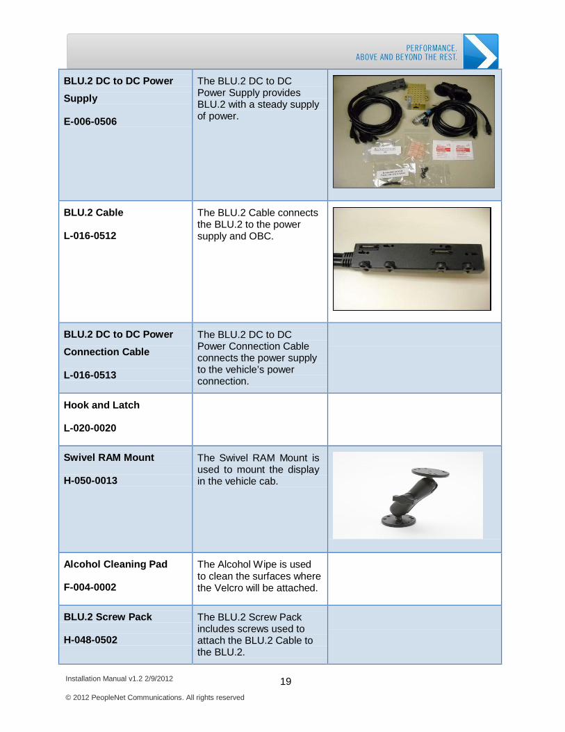
BLU.2 DC to DC Power
Supply E-006-0506
The BLU.2 DC to DC Power Supply provides BLU.2 with a steady supply of power.
BLU.2 Cable L-016-0512
The BLU.2 Cable connects the BLU.2 to the power supply and OBC.
BLU.2 DC to DC Power
Connection Cable L-016-0513
The BLU.2 DC to DC Power Connection Cable connects the power supply to the vehicle’s power connection.
Hook and Latch L-020-0020
Swivel RAM Mount H-050-0013
The Swivel RAM Mount is used to mount the display in the vehicle cab.
Alcohol Cleaning Pad F-004-0002
The Alcohol Wipe is used to clean the surfaces where the Velcro will be attached.
BLU.2 Screw Pack H-048-0502
The BLU.2 Screw Pack includes screws used to attach the BLU.2 Cable to the BLU.2.
Installation Manual v1.2 2/9/2012 20 © 2012 PeopleNet Communications. All rights reserved
Getting Started: PeopleNet Hardware Kits
Fuse Holder B-009-0101
The Fuse Holder holds the 5 Amp Fuse.
5 Amp Fuse B-009-0500
The 5 Amp Fuse protects the BLU.2.
TABLET Hardware Kits
Standard TABLET Kit
Table 13: Standard TABLET
Part: M-010-0505
Description
Picture
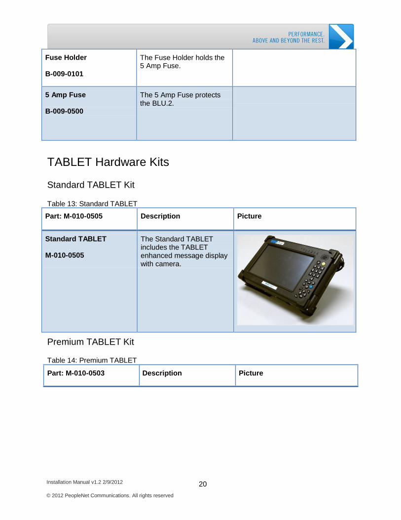
Standard TABLET
M-010-0505
The Standard TABLET includes the TABLET enhanced message display with camera.
Premium TABLET Kit
Table 14: Premium TABLET
Part: M-010-0503 Description Picture
Installation Manual v1.2 2/9/2012 21 © 2012 PeopleNet Communications. All rights reserved
Getting Started: PeopleNet Hardware Kits
Getting Started: PeopleNet Hardware Kits
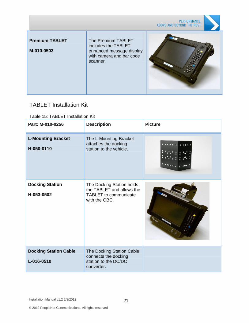
Premium TABLET
M-010-0503
The Premium TABLET includes the TABLET enhanced message display with camera and bar code scanner.
TABLET Installation Kit
Table 15: TABLET Installation Kit
Part: M-010-0256
Description
Picture
L-Mounting Bracket H-050-0110
The L-Mounting Bracket attaches the docking station to the vehicle.
Docking Station H-053-0502
The Docking Station holds the TABLET and allows the TABLET to communicate with the OBC.
Docking Station Cable L-016-0510
The Docking Station Cable connects the docking station to the DC/DC converter.
Installation Manual v1.2 2/9/2012 22 © 2012 PeopleNet Communications. All rights reserved
Getting Started: PeopleNet Hardware Kits
Getting Started: PeopleNet Hardware Kits
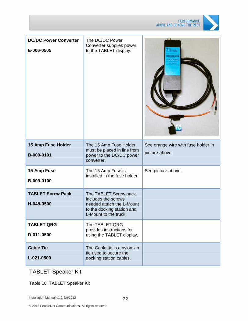
DC/DC Power Converter E-006-0505
The DC/DC Power Converter supplies power to the TABLET display.
15 Amp Fuse Holder B-009-0101
The 15 Amp Fuse Holder must be placed in line from power to the DC/DC power converter.
See orange wire with fuse holder in
picture above.
15 Amp Fuse B-009-0100
The 15 Amp Fuse is installed in the fuse holder.
See picture above.
TABLET Screw Pack H-048-0500
The TABLET Screw pack includes the screws needed attach the L-Mount to the docking station and L-Mount to the truck.
TABLET QRG
D-011-0500
The TABLET QRG provides instructions for using the TABLET display.
Cable Tie L-021-0500
The Cable tie is a nylon zip tie used to secure the docking station cables.
TABLET Speaker Kit
Table 16: TABLET Speaker Kit
Installation Manual v1.2 2/9/2012 23 © 2012 PeopleNet Communications. All rights reserved
Getting Started: PeopleNet Hardware Kits
Part: H-040-0501
Description
Picture
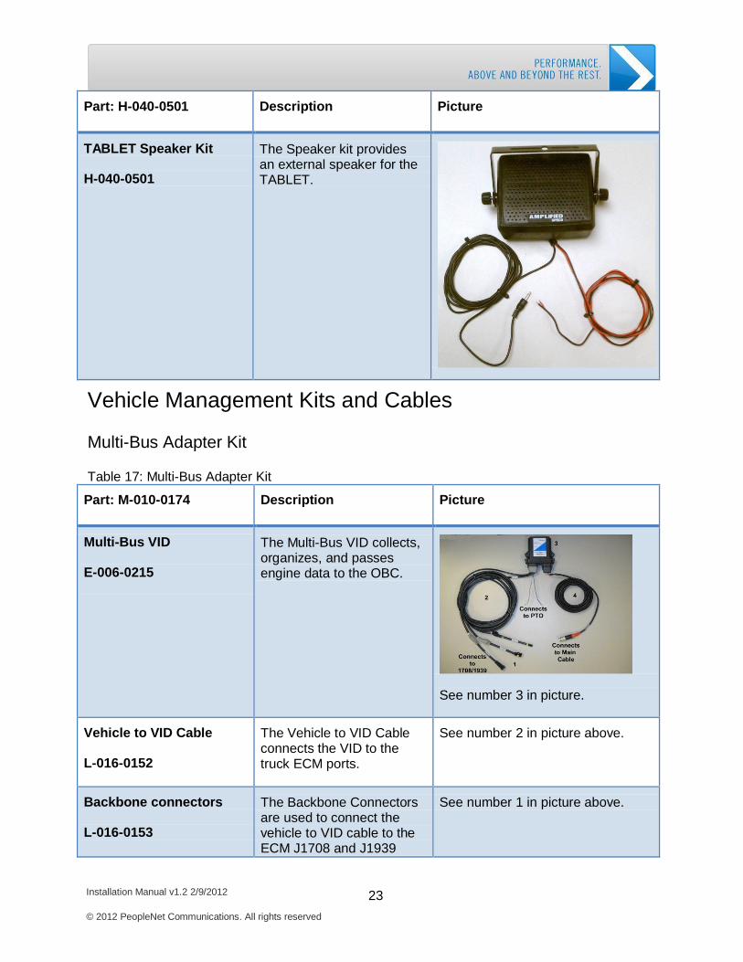
TABLET Speaker Kit H-040-0501
The Speaker kit provides an external speaker for the TABLET.
Vehicle Management Kits and Cables
Multi-Bus Adapter Kit
Table 17: Multi-Bus Adapter Kit
Part: M-010-0174
Description
Picture
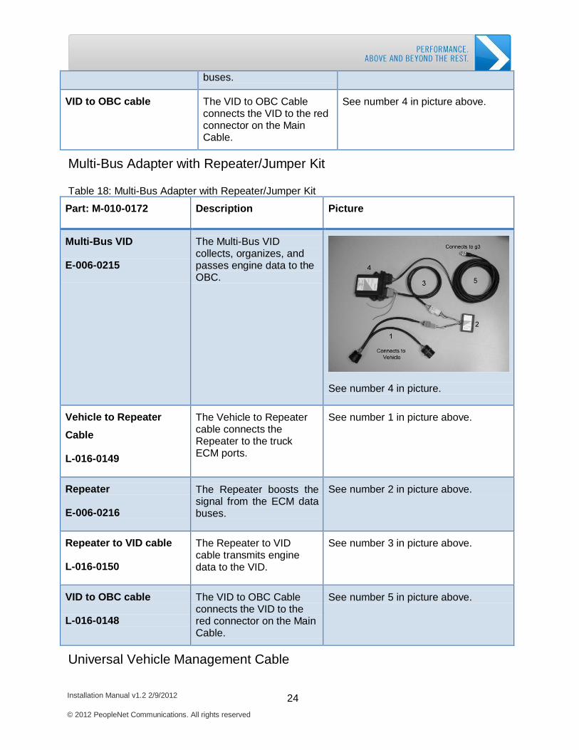
Multi-Bus VID
E-006-0215
The Multi-Bus VID collects, organizes, and passes engine data to the OBC.
See number 3 in picture.
Vehicle to VID Cable L-016-0152
The Vehicle to VID Cable connects the VID to the truck ECM ports.
See number 2 in picture above.
Backbone connectors L-016-0153
The Backbone Connectors are used to connect the vehicle to VID cable to the ECM J1708 and J1939
See number 1 in picture above.
Installation Manual v1.2 2/9/2012 24 © 2012 PeopleNet Communications. All rights reserved
Getting Started: PeopleNet Hardware Kits
buses.
VID to OBC cable
The VID to OBC Cable connects the VID to the red connector on the Main Cable.
See number 4 in picture above.
Multi-Bus Adapter with Repeater/Jumper Kit
Table 18: Multi-Bus Adapter with Repeater/Jumper Kit
Part: M-010-0172
Description
Picture
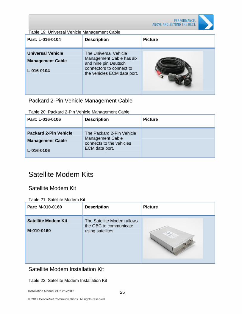
Multi-Bus VID
E-006-0215
The Multi-Bus VID collects, organizes, and passes engine data to the OBC.
See number 4 in picture.
Vehicle to Repeater
Cable L-016-0149
The Vehicle to Repeater cable connects the Repeater to the truck ECM ports.
See number 1 in picture above.
Repeater E-006-0216
The Repeater boosts the signal from the ECM data buses.
See number 2 in picture above.
Repeater to VID cable L-016-0150
The Repeater to VID cable transmits engine data to the VID.
See number 3 in picture above.
VID to OBC cable L-016-0148
The VID to OBC Cable connects the VID to the red connector on the Main Cable.
See number 5 in picture above.
Universal Vehicle Management Cable
Installation Manual v1.2 2/9/2012 25 © 2012 PeopleNet Communications. All rights reserved
Getting Started: PeopleNet Hardware Kits
Table 19: Universal Vehicle Management Cable
Part: L-016-0104
Description
Picture
Universal Vehicle
Management Cable L-016-0104
The Universal Vehicle Management Cable has six and nine pin Deutsch connectors to connect to the vehicles ECM data port.
Packard 2-Pin Vehicle Management Cable
Table 20: Packard 2-Pin Vehicle Management Cable
Part: L-016-0106
Description
Picture
Packard 2-Pin Vehicle
Management Cable L-016-0106
The Packard 2-Pin Vehicle Management Cable connects to the vehicles ECM data port.
Satellite Modem Kits
Satellite Modem Kit
Table 21: Satellite Modem Kit
Part: M-010-0160
Description
Picture
Satellite Modem Kit M-010-0160
The Satellite Modem allows the OBC to communicate using satellites.
Satellite Modem Installation Kit
Table 22: Satellite Modem Installation Kit
Installation Manual v1.2 2/9/2012 26 © 2012 PeopleNet Communications. All rights reserved
Getting Started: PeopleNet Hardware Kits
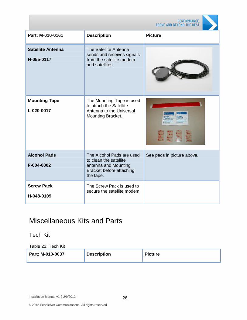
Part: M-010-0161
Description
Picture
Satellite Antenna H-055-0117
The Satellite Antenna sends and receives signals from the satellite modem and satellites.
Mounting Tape L-020-0017
The Mounting Tape is used to attach the Satellite Antenna to the Universal Mounting Bracket.
Alcohol Pads F-004-0002
The Alcohol Pads are used to clean the satellite antenna and Mounting Bracket before attaching the tape.
See pads in picture above.
Screw Pack H-048-0109
The Screw Pack is used to secure the satellite modem.
Miscellaneous Kits and Parts
Tech Kit
Table 23: Tech Kit
Part: M-010-0037 Description Picture
Installation Manual v1.2 2/9/2012 27 © 2012 PeopleNet Communications. All rights reserved
Getting Started: PeopleNet Hardware Kits
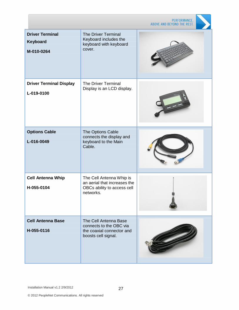
Driver Terminal
Keyboard M-010-0264
The Driver Terminal Keyboard includes the keyboard with keyboard cover.
Driver Terminal Display L-019-0100
The Driver Terminal Display is an LCD display.
Options Cable L-016-0049
The Options Cable connects the display and keyboard to the Main Cable.
Cell Antenna Whip H-055-0104
The Cell Antenna Whip is an aerial that increases the OBCs ability to access cell networks.
Cell Antenna Base H-055-0116
The Cell Antenna Base connects to the OBC via the coaxial connector and boosts cell signal.
Installation Manual v1.2 2/9/2012 28 © 2012 PeopleNet Communications. All rights reserved
Getting Started: PeopleNet Hardware Kits
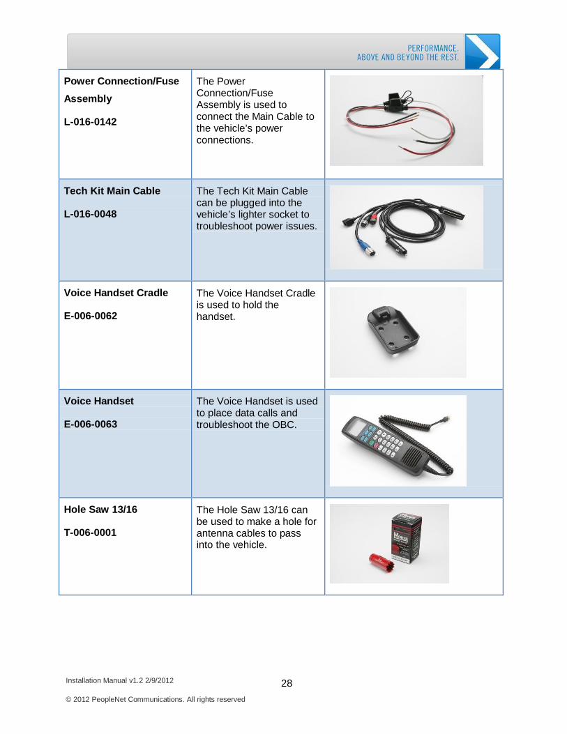
Power Connection/Fuse
Assembly L-016-0142
The Power Connection/Fuse Assembly is used to connect the Main Cable to the vehicle’s power connections.
Tech Kit Main Cable L-016-0048
The Tech Kit Main Cable can be plugged into the vehicle’s lighter socket to troubleshoot power issues.
Voice Handset Cradle E-006-0062
The Voice Handset Cradle is used to hold the handset.
Voice Handset E-006-0063
The Voice Handset is used to place data calls and troubleshoot the OBC.
Hole Saw 13/16 T-006-0001
The Hole Saw 13/16 can be used to make a hole for antenna cables to pass into the vehicle.
Installation Manual v1.2 2/9/2012 29 © 2012 PeopleNet Communications. All rights reserved
Getting Started: PeopleNet Hardware Kits
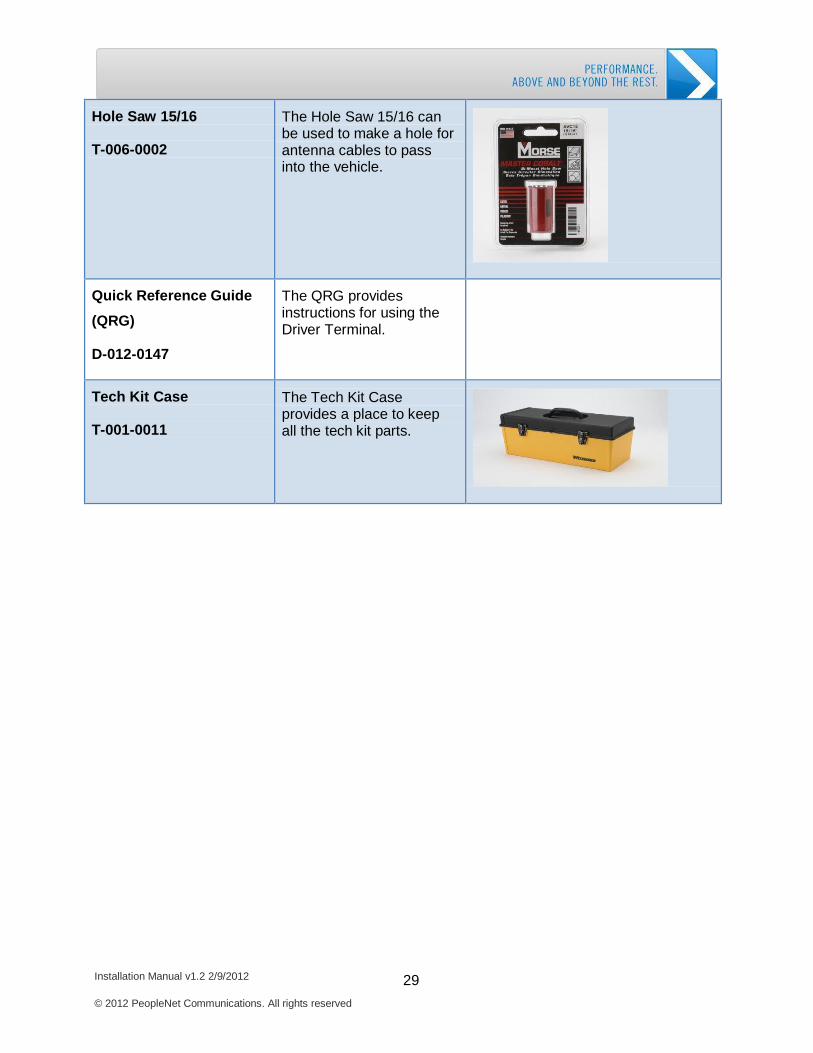
Hole Saw 15/16 T-006-0002
The Hole Saw 15/16 can be used to make a hole for antenna cables to pass into the vehicle.
Quick Reference Guide
(QRG) D-012-0147
The QRG provides instructions for using the Driver Terminal.
Tech Kit Case T-001-0011
The Tech Kit Case provides a place to keep all the tech kit parts.
Installation Manual v1.2 2/9/2012 30 © 2012 PeopleNet Communications. All rights reserved
Getting Started: Tools and Supplies
Tools and Supplies
To install the PeopleNet System, you will need to use multiple tools. Several of the required
tools are included in the Installation Kits, but you will also need your own tools. Please review
the list of tools below, so you have all the tools required to complete the installation.
Required Tools
Adjustable crescent wrench Cordless drill with two battery packs Drill bits ranging from 1/8” to 3/8” Flashlight 1/4" drive ratchet Multi-meter (volts, amps, and ohms) Needle nose pliers Wire crimper Radio removal tools Sockets 1/4" drive Screw bit set including holder and T15, T20, T25, and T27 Torx bits Philips and standard screw driver sets Sockets: standard, deep well, ¼” drive, 3/16” to 9/16” Tape measure 12 volt test light Wire cutter Wire stripper 90° bit holder 13/16” hole saw (included in the installation kit) 15/16” hole saw (included in the installation kit)
Required Supplies
Electrical tape Clear silicone Wire ties Paper towels

Installation Manual v1.2 2/9/2012 31 © 2012 PeopleNet Communications. All rights reserved
Getting Started: Installation Time
Installation Time
It is important to give yourself enough time to complete each installation. Your first several
installations will take between four and six hours each depending on the hardware kits
purchased. As you become more experienced, the average installation should take
approximately two and half hours to complete.
Installation Manual v1.2 2/9/2012 32 © 2012 PeopleNet Communications. All rights reserved
Getting Started: Installation Best Practices
Installation Best Practices
To successfully install the PeopleNet System, it is critical to use the following best practices.
These best practices will ensure the PeopleNet System is safely mounted and functions
properly. These best practices include:
Use safe installation locations Route cables and antennas correctly Secure mounts for hardware and power connections
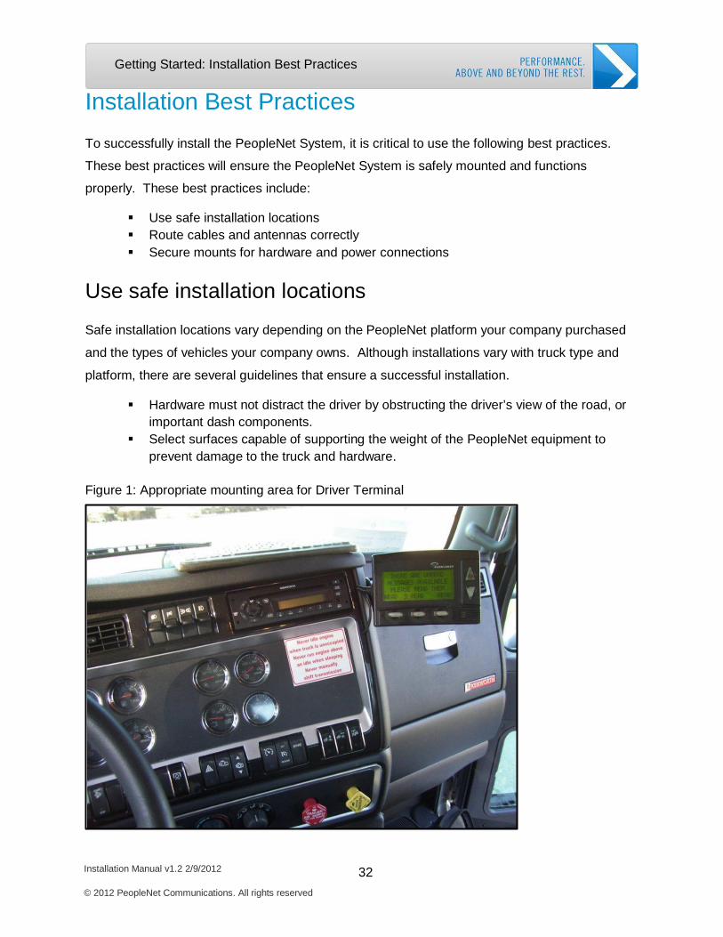
Use safe installation locations
Safe installation locations vary depending on the PeopleNet platform your company purchased
and the types of vehicles your company owns. Although installations vary with truck type and
platform, there are several guidelines that ensure a successful installation.
Hardware must not distract the driver by obstructing the driver’s view of the road, or important dash components.
Select surfaces capable of supporting the weight of the PeopleNet equipment to prevent damage to the truck and hardware.
Figure 1: Appropriate mounting area for Driver Terminal
Installation Manual v1.2 2/9/2012 33 © 2012 PeopleNet Communications. All rights reserved
Getting Started: Installation Best Practices
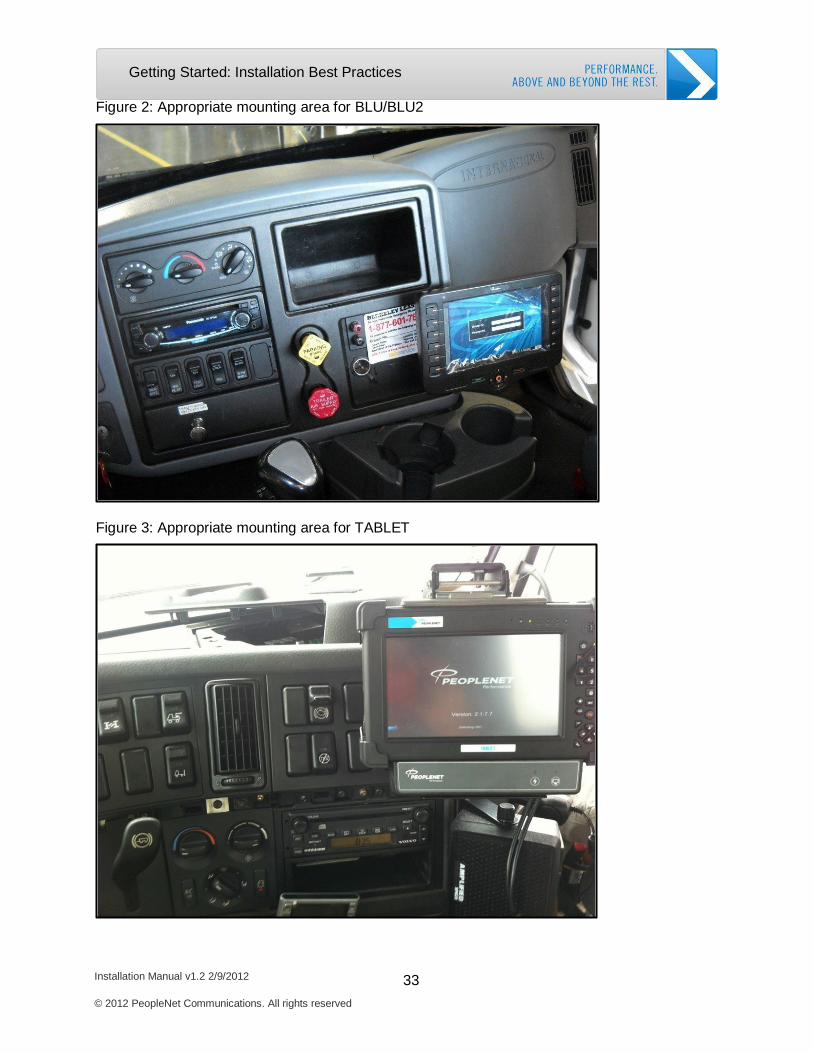
Figure 2: Appropriate mounting area for BLU/BLU2
Figure 3: Appropriate mounting area for TABLET
Installation Manual v1.2 2/9/2012 34 © 2012 PeopleNet Communications. All rights reserved
Getting Started: Installation Best Practices
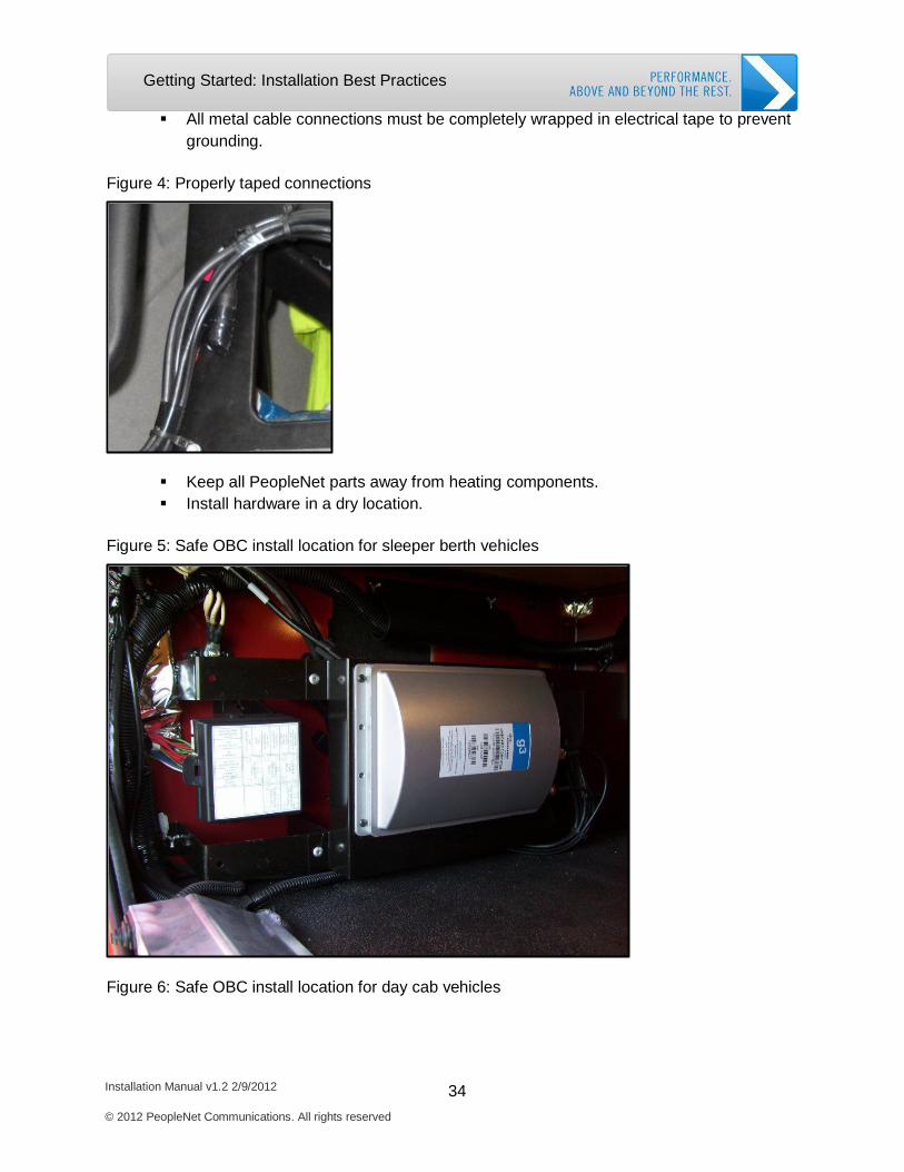
All metal cable connections must be completely wrapped in electrical tape to prevent grounding.
Figure 4: Properly taped connections
Keep all PeopleNet parts away from heating components. Install hardware in a dry location.
Figure 5: Safe OBC install location for sleeper berth vehicles
Figure 6: Safe OBC install location for day cab vehicles
Installation Manual v1.2 2/9/2012 35 © 2012 PeopleNet Communications. All rights reserved
Getting Started: Installation Best Practices
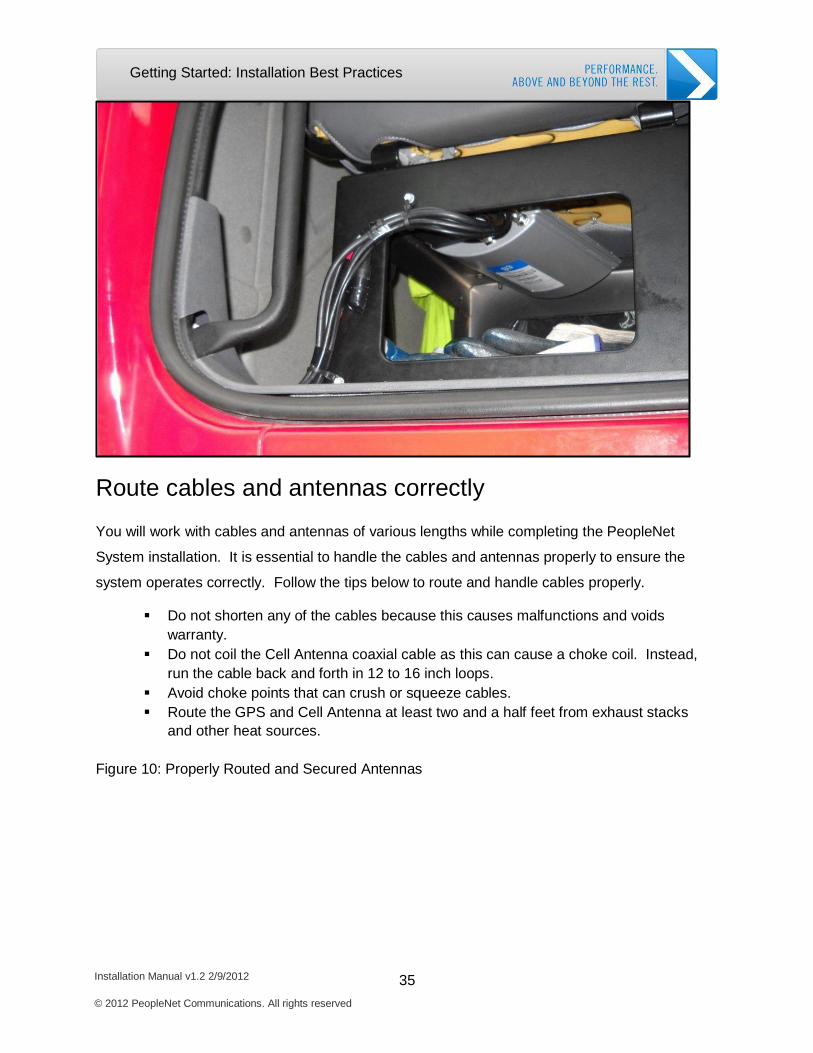
Route cables and antennas correctly
You will work with cables and antennas of various lengths while completing the PeopleNet
System installation. It is essential to handle the cables and antennas properly to ensure the
system operates correctly. Follow the tips below to route and handle cables properly.
Do not shorten any of the cables because this causes malfunctions and voids warranty.
Do not coil the Cell Antenna coaxial cable as this can cause a choke coil. Instead, run the cable back and forth in 12 to 16 inch loops.
Avoid choke points that can crush or squeeze cables. Route the GPS and Cell Antenna at least two and a half feet from exhaust stacks
and other heat sources.
Figure 10: Properly Routed and Secured Antennas
Installation Manual v1.2 2/9/2012 36 © 2012 PeopleNet Communications. All rights reserved
Getting Started: Installation Best Practices
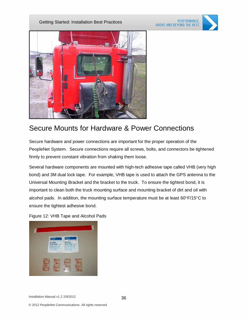
Secure Mounts for Hardware & Power Connections
Secure hardware and power connections are important for the proper operation of the
PeopleNet System. Secure connections require all screws, bolts, and connectors be tightened
firmly to prevent constant vibration from shaking them loose.
Several hardware components are mounted with high-tech adhesive tape called VHB (very high
bond) and 3M dual lock tape. For example, VHB tape is used to attach the GPS antenna to the
Universal Mounting Bracket and the bracket to the truck. To ensure the tightest bond, it is
important to clean both the truck mounting surface and mounting bracket of dirt and oil with
alcohol pads. In addition, the mounting surface temperature must be at least 60°F/15°C to
ensure the tightest adhesive bond.
Figure 12: VHB Tape and Alcohol Pads
Installation Manual v1.2 2/9/2012 37 © 2012 PeopleNet Communications. All rights reserved
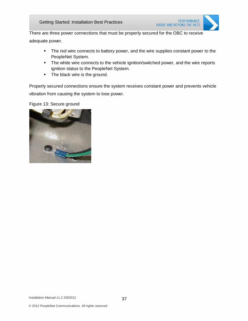
Getting Started: Installation Best Practices
There are three power connections that must be properly secured for the OBC to receive
adequate power.
The red wire connects to battery power, and the wire supplies constant power to the PeopleNet System.
The white wire connects to the vehicle ignition/switched power, and the wire reports ignition status to the PeopleNet System.
The black wire is the ground.
Properly secured connections ensure the system receives constant power and prevents vehicle
vibration from causing the system to lose power.
Figure 13: Secure ground
2. OBC Installation
Required System Components
Install GPS & Cell Antenna
Install Universal Mounting Bracket
Install OBC Computer & Cables
Power Connections
Activate the OBC
Complete Installation Checklist
Installation Manual v1.2 2/9/2012 38
© 2012 PeopleNet Communications. All rights reserved
OBC Installation: System Components
Installation Manual v1.2 2/9/2012 39 © 2012 PeopleNet Communications. All rights reserved
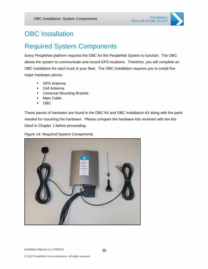
OBC Installation
Required System Components
Every PeopleNet platform requires the OBC for the PeopleNet System to function. The OBC
allows the system to communicate and record GPS locations. Therefore, you will complete an
OBC installation for each truck in your fleet. The OBC installation requires you to install five
major hardware pieces.
GPS Antenna Cell Antenna Universal Mounting Bracket Main Cable OBC
These pieces of hardware are found in the OBC Kit and OBC Installation Kit along with the parts
needed for mounting the hardware. Please compare the hardware kits received with the kits
listed in Chapter 1 before proceeding.
Figure 14: Required System Components
OBC Installation: System Components
Installation Manual v1.2 2/9/2012 40 © 2012 PeopleNet Communications. All rights reserved
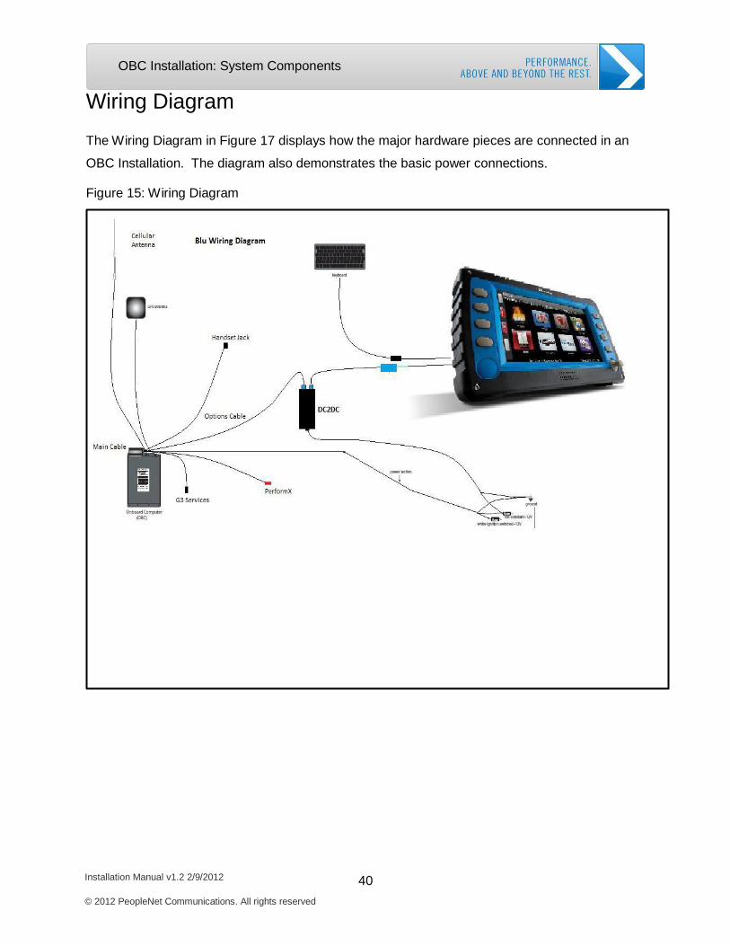
Wiring Diagram
The Wiring Diagram in Figure 17 displays how the major hardware pieces are connected in an
OBC Installation. The diagram also demonstrates the basic power connections.
Figure 15: Wiring Diagram
Installation Manual v1.2 2/9/2012 41 © 2012 PeopleNet Communications. All rights reserved
OBC Installation: Install GPS & Cell Antennas
Install GPS & Cell Antennas
You will begin the installation process by installing the GPS and cell antennas. The GPS
antenna receives signals from the Global Positioning Satellites and delivers the data to the
OBC. The PeopleNet System uses the GPS signals to determine the vehicle’s location. You
must mount the GPS Antenna as instructed for the system to receive GPS signals. For the
vehicle to communicate via the cellular network, the Cell Antenna must also be mounted as
instructed. The PeopleNet System uses the Cell Antenna to send and receive information
between the vehicle and the NOC.
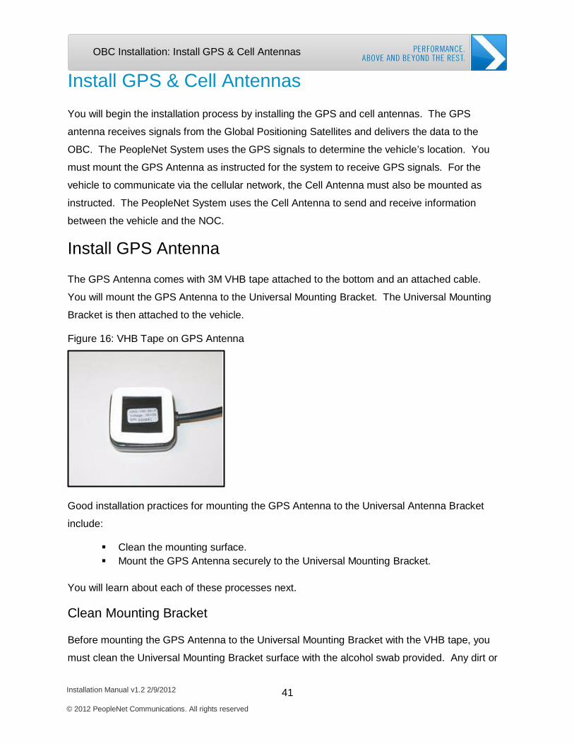
Install GPS Antenna
The GPS Antenna comes with 3M VHB tape attached to the bottom and an attached cable.
You will mount the GPS Antenna to the Universal Mounting Bracket. The Universal Mounting
Bracket is then attached to the vehicle.
Figure 16: VHB Tape on GPS Antenna
Good installation practices for mounting the GPS Antenna to the Universal Antenna Bracket
include:
Clean the mounting surface. Mount the GPS Antenna securely to the Universal Mounting Bracket.
You will learn about each of these processes next.
Clean Mounting Bracket
Before mounting the GPS Antenna to the Universal Mounting Bracket with the VHB tape, you
must clean the Universal Mounting Bracket surface with the alcohol swab provided. Any dirt or
Installation Manual v1.2 2/9/2012 42 © 2012 PeopleNet Communications. All rights reserved
OBC Installation: Install GPS & Cell Antennas
oil on the Universal Mounting Bracket prevents the tape from forming a strong bond. The failure
to bond properly can cause the GPS Antenna to break away from the Universal Mounting
Bracket.
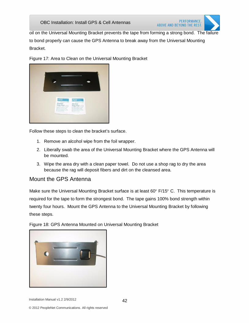
Figure 17: Area to Clean on the Universal Mounting Bracket
Follow these steps to clean the bracket’s surface.
1. Remove an alcohol wipe from the foil wrapper.
2. Liberally swab the area of the Universal Mounting Bracket where the GPS Antenna will be mounted.
3. Wipe the area dry with a clean paper towel. Do not use a shop rag to dry the area because the rag will deposit fibers and dirt on the cleansed area.
Mount the GPS Antenna
Make sure the Universal Mounting Bracket surface is at least 60° F/15° C. This temperature is
required for the tape to form the strongest bond. The tape gains 100% bond strength within
twenty four hours. Mount the GPS Antenna to the Universal Mounting Bracket by following
these steps.
Figure 18: GPS Antenna Mounted on Universal Mounting Bracket
Installation Manual v1.2 2/9/2012 43 © 2012 PeopleNet Communications. All rights reserved
OBC Installation: Install GPS & Cell Antennas
1. Remove the backing from one side of the VHB™ tape.
2. Firmly attach the tape to the bottom of the GPS Antenna by pressing the tape in place for 5 seconds.
3. Remove the backing from the other side of the tape.
4. Position the GPS Antenna on the Universal Mounting Bracket, and press the GPS Antenna firmly in place on the Universal Mounting Bracket for 5 seconds.
Install Cell Antenna
Next, you will mount the Cell Antenna to the Universal Mounting Bracket. The Cell Antenna is
required for the OBC to communicate with the NOC.
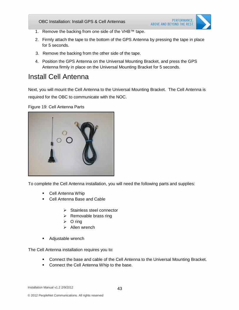
Figure 19: Cell Antenna Parts
To complete the Cell Antenna installation, you will need the following parts and supplies:
Cell Antenna W hip Cell Antenna Base and Cable
Stainless steel connector Removable brass ring O ring Allen wrench
Adjustable wrench
The Cell Antenna installation requires you to:
Connect the base and cable of the Cell Antenna to the Universal Mounting Bracket. Connect the Cell Antenna W hip to the base.
Installation Manual v1.2 2/9/2012 44 © 2012 PeopleNet Communications. All rights reserved
OBC Installation: Install GPS & Cell Antennas
Connect Cable and Base to Universal Mounting Bracket
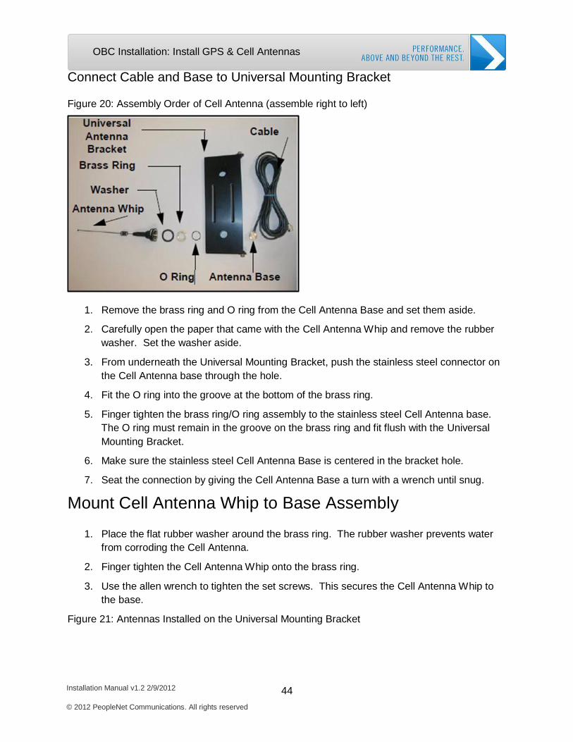
Figure 20: Assembly Order of Cell Antenna (assemble right to left)
1. Remove the brass ring and O ring from the Cell Antenna Base and set them aside.
2. Carefully open the paper that came with the Cell Antenna Whip and remove the rubber washer. Set the washer aside.
3. From underneath the Universal Mounting Bracket, push the stainless steel connector on the Cell Antenna base through the hole.
4. Fit the O ring into the groove at the bottom of the brass ring.
5. Finger tighten the brass ring/O ring assembly to the stainless steel Cell Antenna base. The O ring must remain in the groove on the brass ring and fit flush with the Universal Mounting Bracket.
6. Make sure the stainless steel Cell Antenna Base is centered in the bracket hole.
7. Seat the connection by giving the Cell Antenna Base a turn with a wrench until snug.
Mount Cell Antenna Whip to Base Assembly
1. Place the flat rubber washer around the brass ring. The rubber washer prevents water from corroding the Cell Antenna.
2. Finger tighten the Cell Antenna Whip onto the brass ring.
3. Use the allen wrench to tighten the set screws. This secures the Cell Antenna Whip to the base.
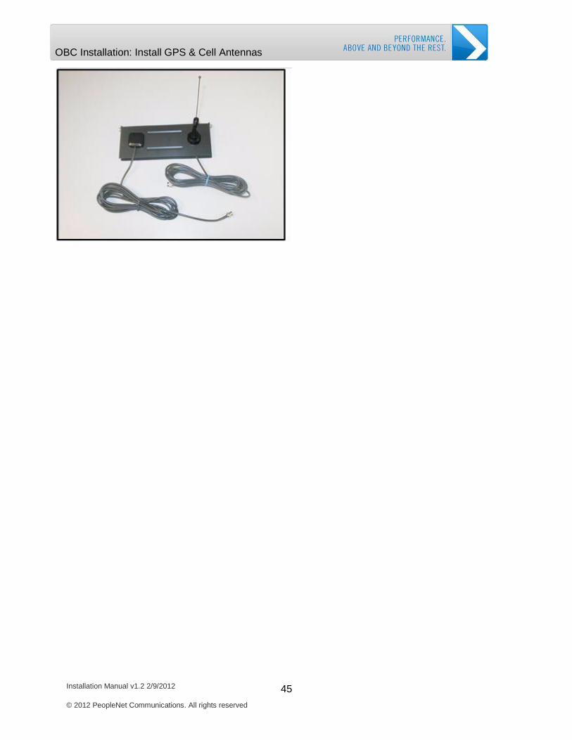
Figure 21: Antennas Installed on the Universal Mounting Bracket
Installation Manual v1.2 2/9/2012 45 © 2012 PeopleNet Communications. All rights reserved
OBC Installation: Install GPS & Cell Antennas

Installation Manual v1.2 2/9/2012 46 © 2012 PeopleNet Communications. All rights reserved
OBC Inst OBC Installation: Install GPS & Cell
Install Universal Mounting Bracket
Now that you have mounted the Cell and GPS antennas to the Universal Mounting Bracket, you
will next mount the bracket to the vehicle. To ensure a clear signal, follow these guidelines to
select a location and mount the antenna bracket.
Mount the bracket high on the vehicle in an area that provides a clear line of sight to the sky for both the GPS and Cell antennas.
Make sure no metal covers the GPS antenna. Metal prevents the GPS signal from reaching the GPS Antenna.
Mount the Universal Mounting Bracket, so the GPS antenna is as flat (horizontal) as possible. The Universal Mounting Bracket should stick out like a flat shelf from the vehicle.
Figure 21: Universal Mounting Bracket Mounted on Vehicle
Attach VHB Tape to the Universal Mounting Bracket
You will mount the universal mounting bracket to the vehicle using the strip of VHB tape
included in the installation kit. You should only mount the Universal Mounting Bracket to the
vehicle after attaching the GPS and Cell Antennas to the Universal Mounting Bracket. Follow
these steps to attach the tape to the Universal Mounting Bracket.
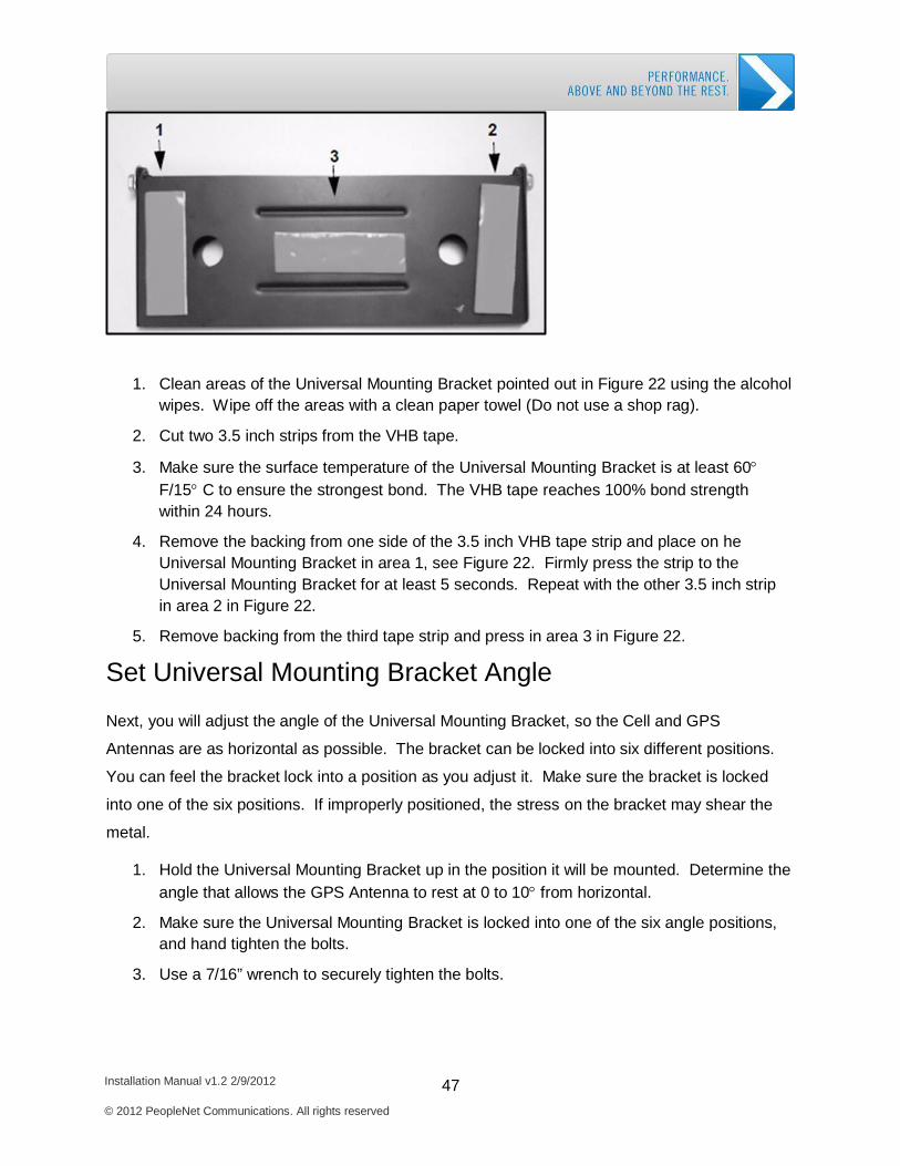
Figure 22: Tape Placement on Universal Mounting Bracket
Installation Manual v1.2 2/9/2012 47 © 2012 PeopleNet Communications. All rights reserved
OBC Inst OBC Installation: Install GPS & Cell
1. Clean areas of the Universal Mounting Bracket pointed out in Figure 22 using the alcohol wipes. Wipe off the areas with a clean paper towel (Do not use a shop rag).
2. Cut two 3.5 inch strips from the VHB tape.
3. Make sure the surface temperature of the Universal Mounting Bracket is at least 60° F/15° C to ensure the strongest bond. The VHB tape reaches 100% bond strength within 24 hours.
4. Remove the backing from one side of the 3.5 inch VHB tape strip and place on he Universal Mounting Bracket in area 1, see Figure 22. Firmly press the strip to the Universal Mounting Bracket for at least 5 seconds. Repeat with the other 3.5 inch strip in area 2 in Figure 22.
5. Remove backing from the third tape strip and press in area 3 in Figure 22.
Set Universal Mounting Bracket Angle
Next, you will adjust the angle of the Universal Mounting Bracket, so the Cell and GPS
Antennas are as horizontal as possible. The bracket can be locked into six different positions.
You can feel the bracket lock into a position as you adjust it. Make sure the bracket is locked
into one of the six positions. If improperly positioned, the stress on the bracket may shear the
metal.
1. Hold the Universal Mounting Bracket up in the position it will be mounted. Determine the angle that allows the GPS Antenna to rest at 0 to 10° from horizontal.
2. Make sure the Universal Mounting Bracket is locked into one of the six angle positions, and hand tighten the bolts.
3. Use a 7/16” wrench to securely tighten the bolts.

Installation Manual v1.2 2/9/2012 48 © 2012 PeopleNet Communications. All rights reserved
OBC Inst OBC Installation: Install GPS & Cell OBC Installation: Install GPS & Cell Antennas
Mount Universal Mounting Bracket Bracket on Vehicle
The Universal Mounting Bracket is now ready to be attached to the vehicle. Make sure you
choose a position at least two and a half feet from heat sources and with a clear line of sight to
the sky. You will also need to make sure no metal overhangs the GPS and Cell Antenna.
When completed, your Universal Mounting Bracket will look like the bracket in Figure 23.
Follow these steps to mount the Universal Mounting Bracket to the vehicle.
1. Clean the mounting surface of the vehicle with alcohol wipes to remove oil and dirt. Dry the surface with a paper towel.
2. Remove the backing on each piece of VHB tape attached to the Universal Mounting Bracket.
3. Position the Universal Mounting Bracket on the cleaned area of the vehicle, and press
the Universal Mounting Bracket firmly in place for at least 5 seconds to make a solid bond. The VHB tape achieves 100% bond strength within 24 hours.
Installation Manual v1.2 2/9/2012 49 © 2012 PeopleNet Communications. All rights reserved
OBC Installation: Install OBC and Cables
Install OBC and Cables
After mounting the antennas to the Universal Mounting Bracket and the Universal Mounting
Bracket to the vehicle, you will run the antenna cables into the vehicle, attach the antenna
cables to the OBC, and mount the OBC securely to the vehicle.
Run Antenna Cables into Vehicle
The cables for the GPS and Cell Antennas need to be run into the vehicle. When handling the
cables, it is essential you follow these basic rules:
Never pull on the cable connectors; pull only on the cable. Never coil the coaxial antenna cables, as this causes a choke coil. Never run cables in a manner that interferes with the driver’s ability to safely operate
the vehicle.
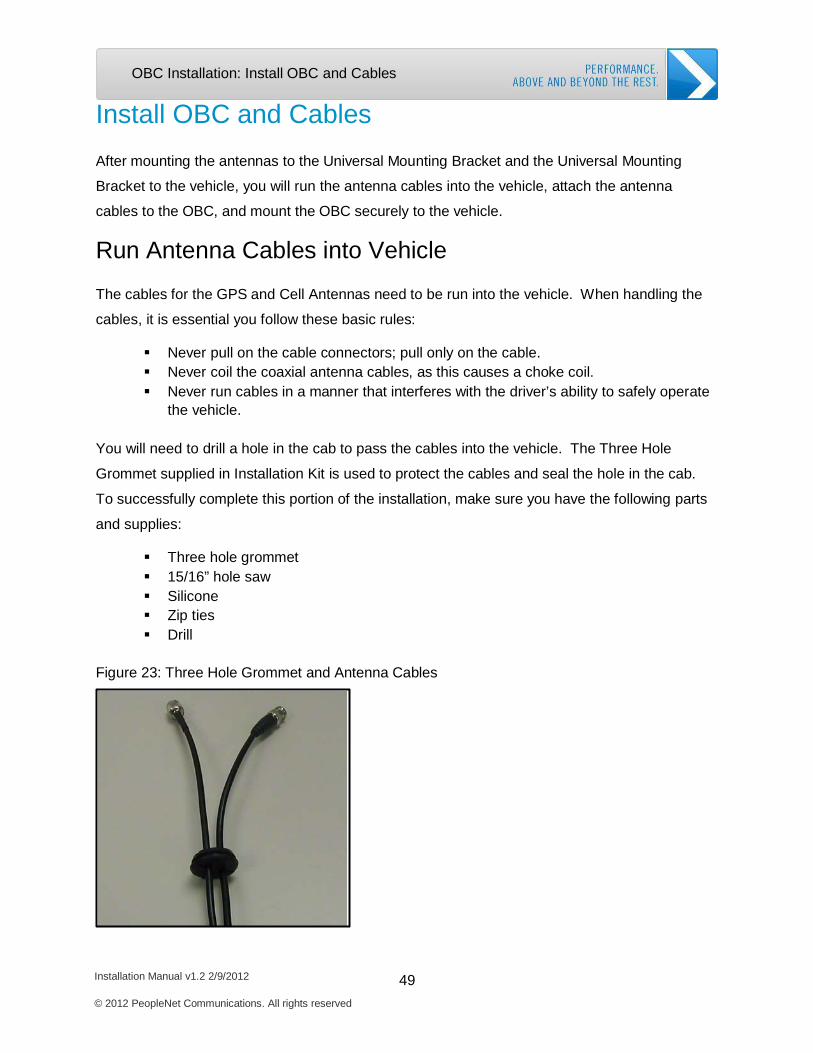
You will need to drill a hole in the cab to pass the cables into the vehicle. The Three Hole
Grommet supplied in Installation Kit is used to protect the cables and seal the hole in the cab.
To successfully complete this portion of the installation, make sure you have the following parts
and supplies:
Three hole grommet 15/16” hole saw Silicone Zip ties Drill
Figure 23: Three Hole Grommet and Antenna Cables

Installation Manual v1.2 2/9/2012 50 © 2012 PeopleNet Communications. All rights reserved
OBC Installation: Install OBC and Cables
1. Use the 15/16” hole saw from the Tech Kit to drill a hole in the vehicle where the cables will pass into the cab.
2. Run the GPS and Cell Antenna cables through the hole and into the vehicle’s interior.
Make sure the cables do not run within two and a half feet of the vehicles stacks or other heat source.
3. The Three Hole Grommet has splits to ease pushing the cables into the holes. Using the section of cables outside the vehicle, push the cables into their own hole in the grommet. The third hole remains empty.
4. Push the Three Hole Grommet into the hole from outside the vehicle.
5. Cover the entire Three Hole Grommet with silicone.
Figure 24: Cables Secured to Vehicle
6. Follow the example in Figure 26 to secure the cables where they enter the vehicle and any cabling run outside the vehicle.
7. String any excess cabling back and forth in the cab to prevent a choke coil.
Installation Manual v1.2 2/9/2012 51 © 2012 PeopleNet Communications. All rights reserved
OBC Installation: Install OBC and Cables
8. Leave the ends of the cables free to connect to the OBC.
Mount the OBC
When mounting the OBC, it is very important to select a safe and secure location. Safe OBC
mounting locations will differ depending on the vehicle type. The OBC mounting location must
meet these requirements:
The location must be at least two and half feet away from any heating components. The location must not interfere with operation of the vehicle. The location must have adequate room so cables and connectors are not strained. The location must remain dry at all times and provide a secure mount for the OBC. The OBC must be mounted with the cable connections pointed horizontally or
downward. This prevents moisture from entering the OBC through the connections.
If you are unsure where to mount the OBC, please contact PeopleNet Customer Support. We
will be happy to provide assistance.
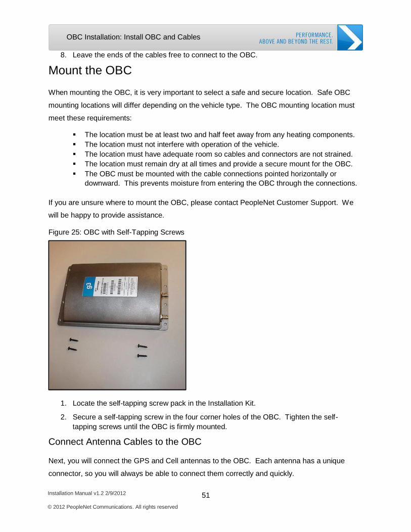
Figure 25: OBC with Self-Tapping Screws
1. Locate the self-tapping screw pack in the Installation Kit.
2. Secure a self-tapping screw in the four corner holes of the OBC. Tighten the self- tapping screws until the OBC is firmly mounted.
Connect Antenna Cables to the OBC
Next, you will connect the GPS and Cell antennas to the OBC. Each antenna has a unique
connector, so you will always be able to connect them correctly and quickly.
Installation Manual v1.2 2/9/2012 52 © 2012 PeopleNet Communications. All rights reserved
OBC Installation: Install OBC and Cables
The GPS Antenna is a push and twist BNC connector.
The Cell Antenna is a TNC screw connector.
Connect the GPS and Cell Antenna cables to the OBC by following these steps.
1. Push and twist the GPS Antenna BNC connector onto the OBC connection. Twist the
connector to lock in place.
2. Screw the TNC Cell Antenna connector onto the OBC. Hand tighten the connector. Make sure the connector is secure, but do not over tighten.
3. Make a drip loop on the GPS and Cell Antenna cables. The drip loop prevents moisture
from entering the OBC through the antenna connections.
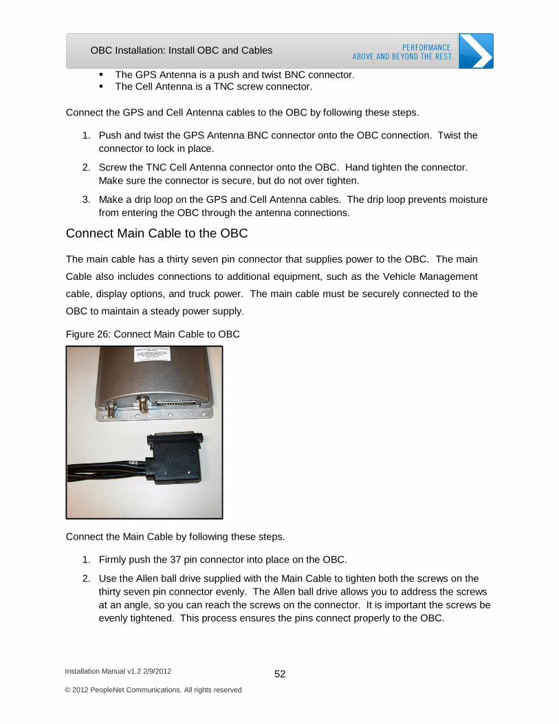
Connect Main Cable to the OBC
The main cable has a thirty seven pin connector that supplies power to the OBC. The main
Cable also includes connections to additional equipment, such as the Vehicle Management
cable, display options, and truck power. The main cable must be securely connected to the
OBC to maintain a steady power supply.
Figure 26: Connect Main Cable to OBC
Connect the Main Cable by following these steps.
1. Firmly push the 37 pin connector into place on the OBC.
2. Use the Allen ball drive supplied with the Main Cable to tighten both the screws on the thirty seven pin connector evenly. The Allen ball drive allows you to address the screws at an angle, so you can reach the screws on the connector. It is important the screws be evenly tightened. This process ensures the pins connect properly to the OBC.
Installation Manual v1.2 2/9/2012 53 © 2012 PeopleNet Communications. All rights reserved
OBC Installation: Power Connections
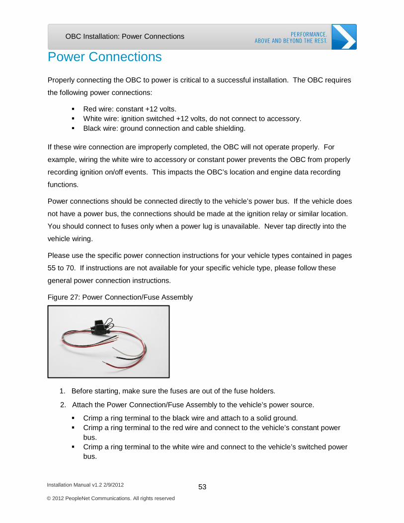
Power Connections
Properly connecting the OBC to power is critical to a successful installation. The OBC requires
the following power connections:
Red wire: constant +12 volts. White wire: ignition switched +12 volts, do not connect to accessory. Black wire: ground connection and cable shielding.
If these wire connection are improperly completed, the OBC will not operate properly. For
example, wiring the white wire to accessory or constant power prevents the OBC from properly
recording ignition on/off events. This impacts the OBC’s location and engine data recording
functions.
Power connections should be connected directly to the vehicle’s power bus. If the vehicle does
not have a power bus, the connections should be made at the ignition relay or similar location.
You should connect to fuses only when a power lug is unavailable. Never tap directly into the
vehicle wiring.
Please use the specific power connection instructions for your vehicle types contained in pages
55 to 70. If instructions are not available for your specific vehicle type, please follow these
general power connection instructions.
Figure 27: Power Connection/Fuse Assembly
1. Before starting, make sure the fuses are out of the fuse holders.
2. Attach the Power Connection/Fuse Assembly to the vehicle’s power source.
Crimp a ring terminal to the black wire and attach to a solid ground. Crimp a ring terminal to the red wire and connect to the vehicle’s constant power
bus. Crimp a ring terminal to the white wire and connect to the vehicle’s switched power
bus.
Installation Manual v1.2 2/9/2012 54 © 2012 PeopleNet Communications. All rights reserved
OBC Installation: Power Connections
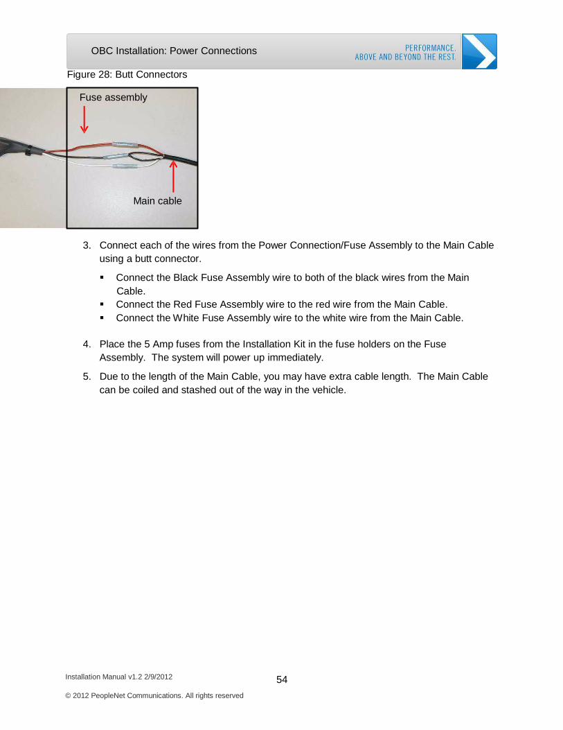
Figure 28: Butt Connectors
Fuse assembly
Main cable
3. Connect each of the wires from the Power Connection/Fuse Assembly to the Main Cable using a butt connector.
Connect the Black Fuse Assembly wire to both of the black wires from the Main Cable.
Connect the Red Fuse Assembly wire to the red wire from the Main Cable. Connect the W hite Fuse Assembly wire to the white wire from the Main Cable.
4. Place the 5 Amp fuses from the Installation Kit in the fuse holders on the Fuse
Assembly. The system will power up immediately.
5. Due to the length of the Main Cable, you may have extra cable length. The Main Cable can be coiled and stashed out of the way in the vehicle.
Installation Manual v1.2 2/9/2012 55 © 2012 PeopleNet Communications. All rights reserved
OBC Installation: Power Connections
Vehicle Specific Power Connections
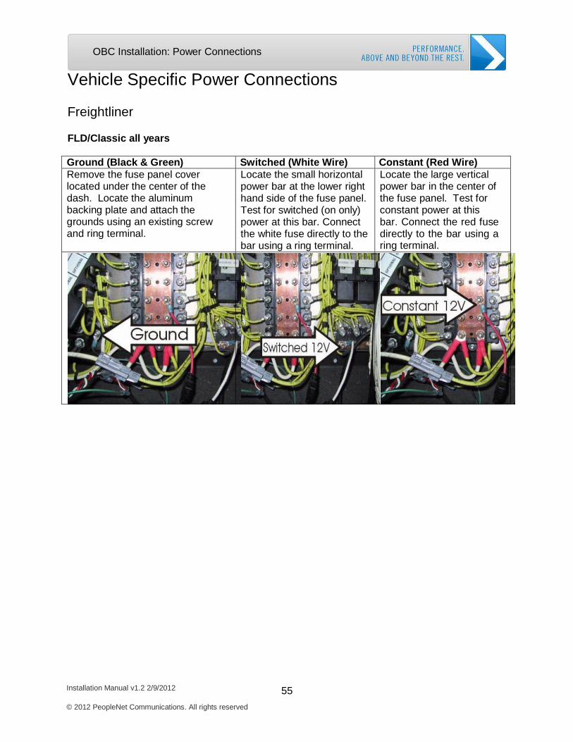
Freightliner
FLD/Classic all years
Ground (Black & Green) Switched (White Wire) Constant (Red Wire) Remove the fuse panel cover located under the center of the dash. Locate the aluminum backing plate and attach the grounds using an existing screw and ring terminal.
Locate the small horizontal power bar at the lower right hand side of the fuse panel. Test for switched (on only) power at this bar. Connect the white fuse directly to the bar using a ring terminal.
Locate the large vertical power bar in the center of the fuse panel. Test for constant power at this bar. Connect the red fuse directly to the bar using a ring terminal.
Installation Manual v1.2 2/9/2012 56 © 2012 PeopleNet Communications. All rights reserved
OBC Installation: Power Connections
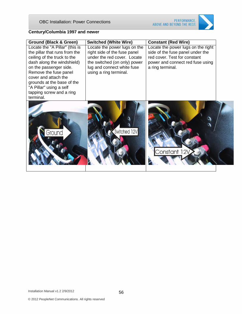
Century/Columbia 1997 and newer
Ground (Black & Green) Switched (White Wire) Constant (Red Wire) Locate the "A Pillar" (this is the pillar that runs from the ceiling of the truck to the dash along the windshield) on the passenger side. Remove the fuse panel cover and attach the grounds at the base of the "A Pillar" using a self tapping screw and a ring terminal.
Locate the power lugs on the right side of the fuse panel under the red cover. Locate the switched (on only) power lug and connect white fuse using a ring terminal.
Locate the power lugs on the right side of the fuse panel under the red cover. Test for constant power and connect red fuse using a ring terminal.
Installation Manual v1.2 2/9/2012 57 © 2012 PeopleNet Communications. All rights reserved
OBC Installation: Power Connections
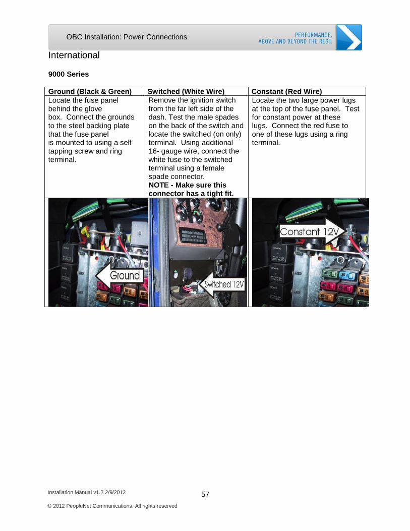
International
9000 Series
Ground (Black & Green) Switched (White Wire) Constant (Red Wire) Locate the fuse panel behind the glove box. Connect the grounds to the steel backing plate that the fuse panel is mounted to using a self tapping screw and ring terminal.
Remove the ignition switch from the far left side of the dash. Test the male spades on the back of the switch and locate the switched (on only) terminal. Using additional 16- gauge wire, connect the white fuse to the switched terminal using a female spade connector. NOTE - Make sure this connector has a tight fit.
Locate the two large power lugs at the top of the fuse panel. Test for constant power at these lugs. Connect the red fuse to one of these lugs using a ring terminal.
Installation Manual v1.2 2/9/2012 58 © 2012 PeopleNet Communications. All rights reserved
OBC Installation: Power Connections
Kenworth and Peterbilt
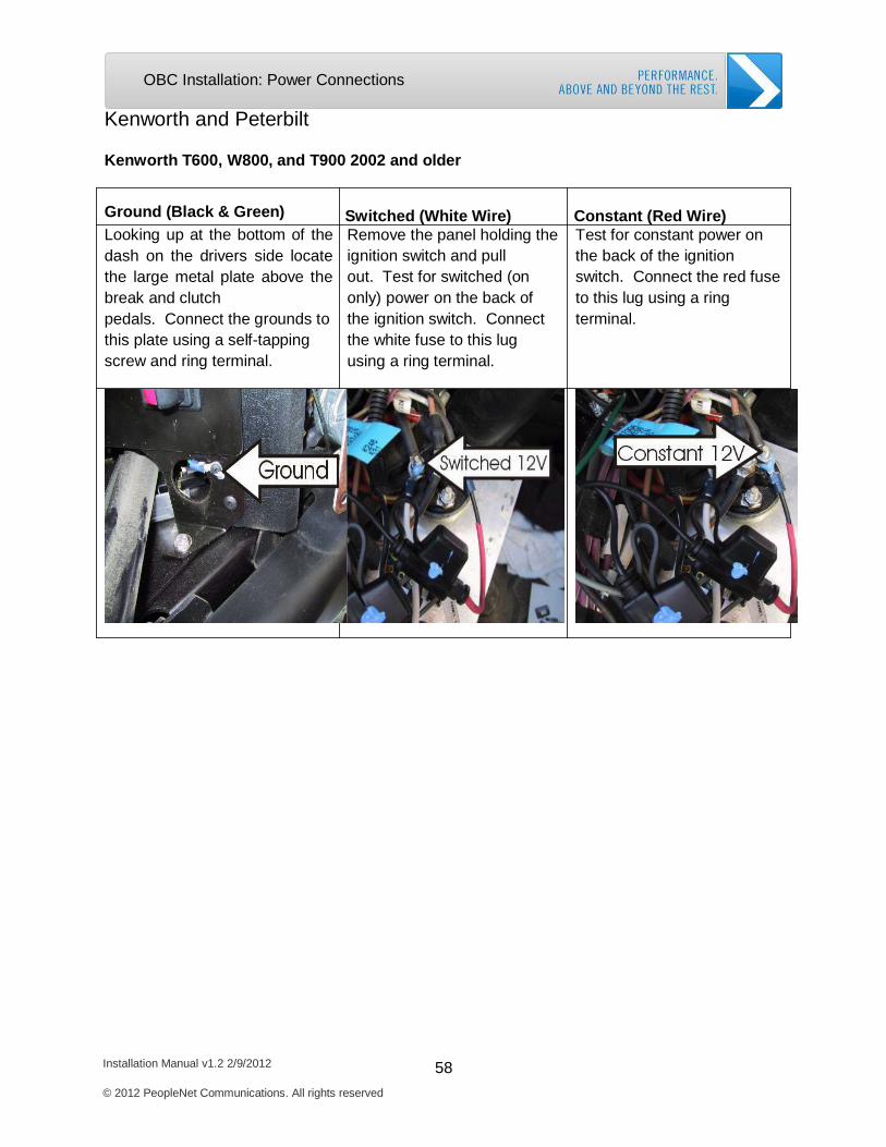
Kenworth T600, W800, and T900 2002 and older
Ground (Black & Green) Switched (White Wire) Constant (Red Wire) Looking up at the bottom of the dash on the drivers side locate the large metal plate above the break and clutch pedals. Connect the grounds to this plate using a self-tapping screw and ring terminal.
Remove the panel holding the ignition switch and pull out. Test for switched (on only) power on the back of the ignition switch. Connect the white fuse to this lug using a ring terminal.
Test for constant power on the back of the ignition switch. Connect the red fuse to this lug using a ring terminal.
Installation Manual v1.2 2/9/2012 59 © 2012 PeopleNet Communications. All rights reserved
OBC Installation: Power Connections
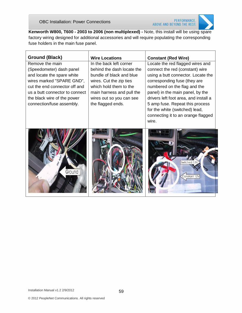
Kenworth W800, T600 - 2003 to 2006 (non multiplexed) - Note, this install will be using spare factory wiring designed for additional accessories and will require populating the corresponding fuse holders in the main fuse panel.
Ground (Black)
Wire Locations
Constant (Red Wire)
Remove the main (Speedometer) dash panel and locate the spare white wires marked "SPARE GND", cut the end connector off and us a butt connector to connect the black wire of the power connection/fuse assembly.
In the back left corner behind the dash locate the bundle of black and blue wires. Cut the zip ties which hold them to the main harness and pull the wires out so you can see the flagged ends.
Locate the red flagged wires and connect the red (constant) wire using a butt connector. Locate the corresponding fuse (they are numbered on the flag and the panel) in the main panel, by the drivers left foot area, and install a 5 amp fuse. Repeat this process for the white (switched) lead, connecting it to an orange flagged wire.

Installation Manual v1.2 2/9/2012 60 © 2012 PeopleNet Communications. All rights reserved
OBC Installation: Power Connections
Kenworth T2000 model - Note this power connection requires 2 “Harness Spare Connectors”, Peterbilt Part # 16-09171 (About $5.00) or Kenworth Part # P92-1185-2000 (About $35.00). They are exactly the same part.
Figure 29: Harness Spare Connector
Ground (Black & Green)
Switched (White Wire)
Constant (Red Wire)
Locate the fuse panel in front of the passengers seat, behind the glove box. Insert a “Harness Spare Connector” into the second row of open terminals (refer to the fuse panel cover for the “Battery” correct slot). Connect grounds to the black lead using a butt connector.
Insert another “Harness Spare Connector” into the second row of the fuse panel (refer to the fuse panel cover the correct “Ignition” slot). Test the red lead for switched (on only) power. Connect the white fuse to the red lead of the “Harness Spare Connector” using a butt connector.
Test the red lead for constant power on the first “Harness Spare Connector”. Connect the red fuse to the red lead of the “Harness Spare Connector” using a butt connector.
Installation Manual v1.2 2/9/2012 61 © 2012 PeopleNet Communications. All rights reserved
OBC Installation: Power Connections
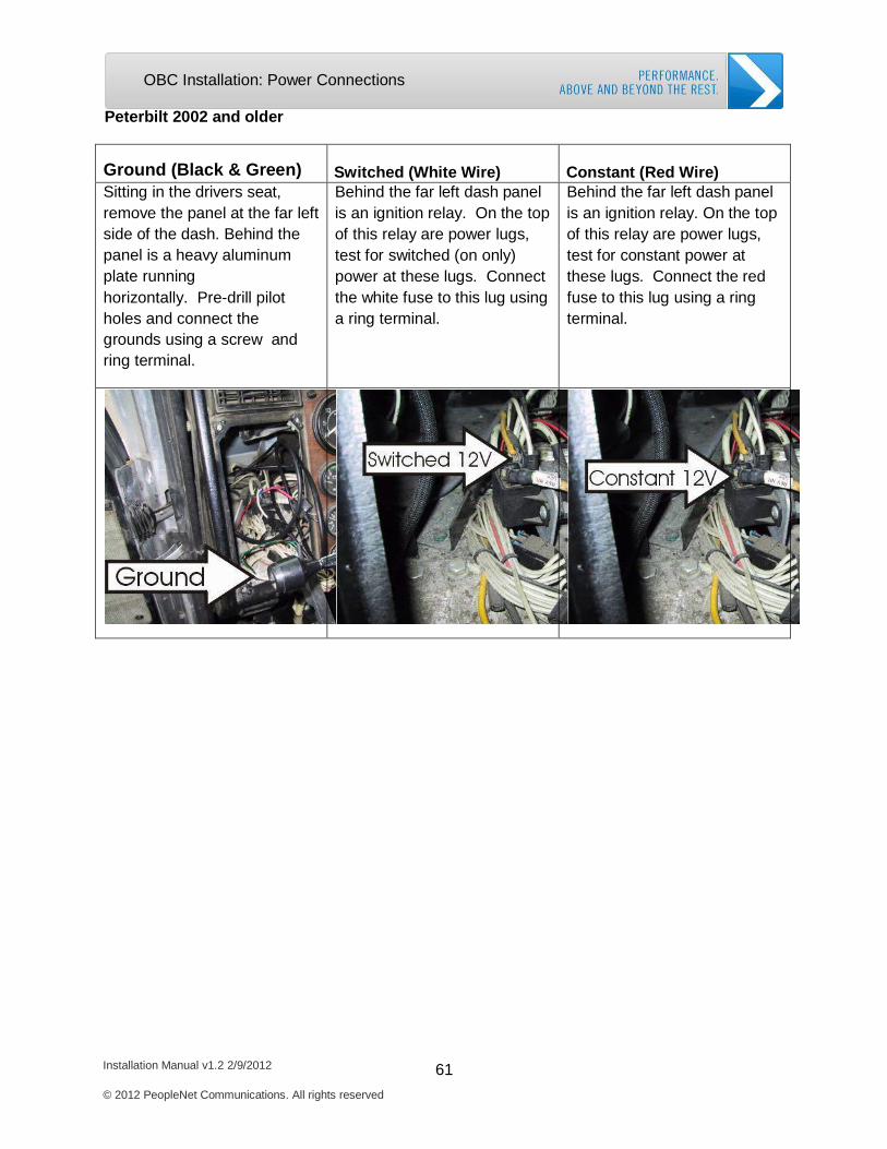
Peterbilt 2002 and older
Ground (Black & Green)
Switched (White Wire)
Constant (Red Wire)
Sitting in the drivers seat, remove the panel at the far left side of the dash. Behind the panel is a heavy aluminum plate running horizontally. Pre-drill pilot holes and connect the grounds using a screw and ring terminal.
Behind the far left dash panel is an ignition relay. On the top of this relay are power lugs, test for switched (on only) power at these lugs. Connect the white fuse to this lug using a ring terminal.
Behind the far left dash panel is an ignition relay. On the top of this relay are power lugs, test for constant power at these lugs. Connect the red fuse to this lug using a ring terminal.
Installation Manual v1.2 2/9/2012 62 © 2012 PeopleNet Communications. All rights reserved
OBC Installation: Power Connections
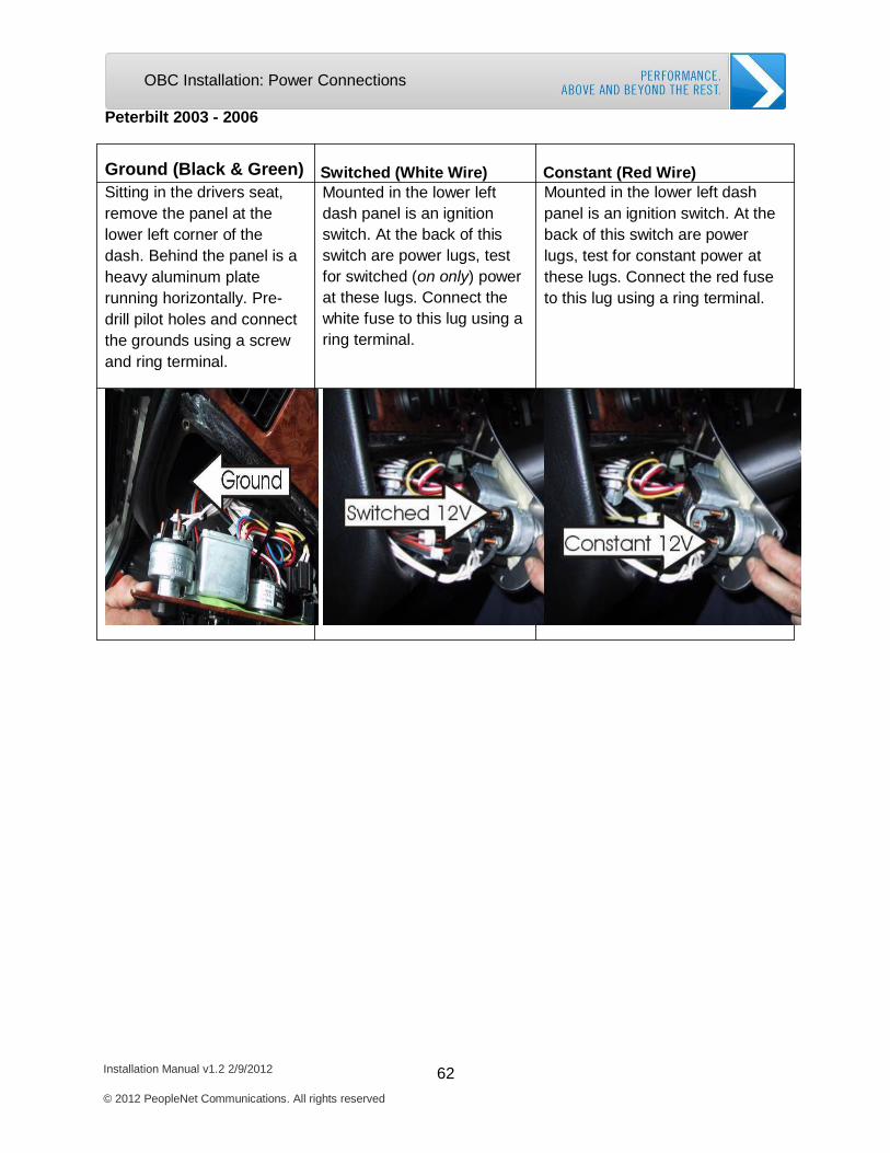
Peterbilt 2003 - 2006
Ground (Black & Green) Switched (White Wire) Constant (Red Wire) Sitting in the drivers seat, remove the panel at the lower left corner of the dash. Behind the panel is a heavy aluminum plate running horizontally. Pre- drill pilot holes and connect the grounds using a screw and ring terminal.
Mounted in the lower left dash panel is an ignition switch. At the back of this switch are power lugs, test for switched (on only) power at these lugs. Connect the white fuse to this lug using a ring terminal.
Mounted in the lower left dash panel is an ignition switch. At the back of this switch are power lugs, test for constant power at these lugs. Connect the red fuse to this lug using a ring terminal.
Installation Manual v1.2 2/9/2012 63 © 2012 PeopleNet Communications. All rights reserved
OBC Installation: Power Connections
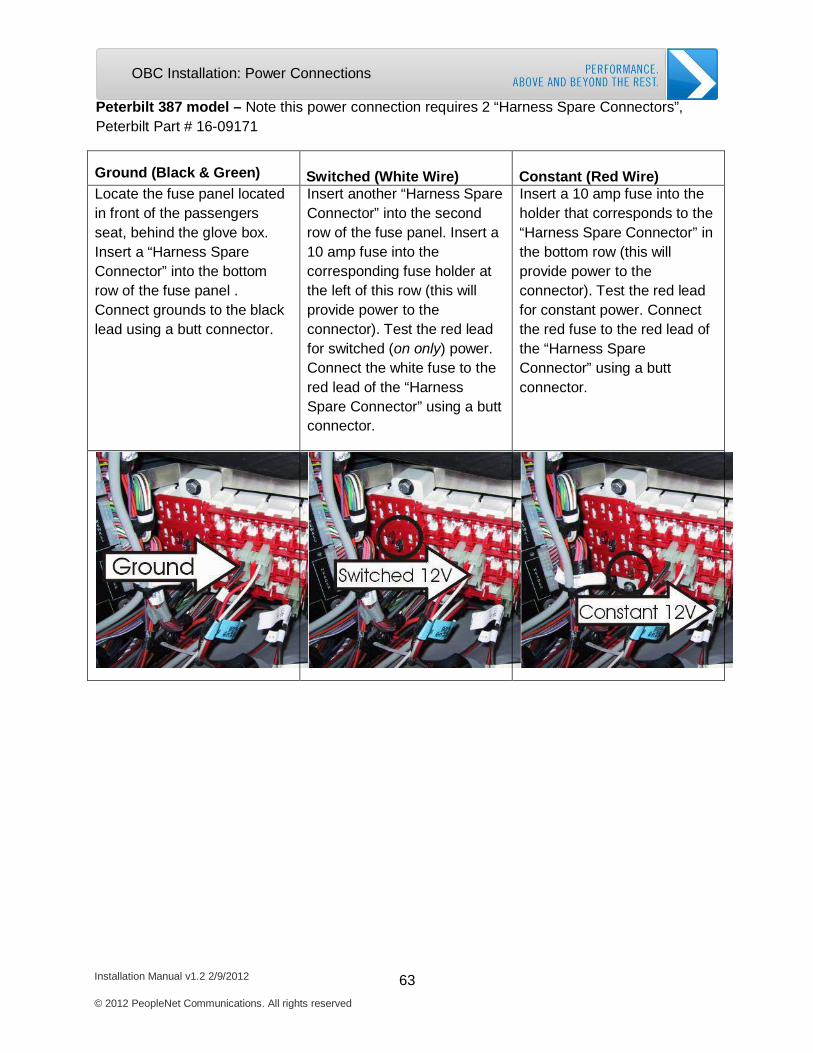
Peterbilt 387 model – Note this power connection requires 2 “Harness Spare Connectors”, Peterbilt Part # 16-09171
Ground (Black & Green)
Switched (White Wire)
Constant (Red Wire)
Locate the fuse panel located in front of the passengers seat, behind the glove box. Insert a “Harness Spare Connector” into the bottom row of the fuse panel . Connect grounds to the black lead using a butt connector.
Insert another “Harness Spare Connector” into the second row of the fuse panel. Insert a 10 amp fuse into the corresponding fuse holder at the left of this row (this will provide power to the connector). Test the red lead for switched (on only) power. Connect the white fuse to the red lead of the “Harness Spare Connector” using a butt connector.
Insert a 10 amp fuse into the holder that corresponds to the “Harness Spare Connector” in the bottom row (this will provide power to the connector). Test the red lead for constant power. Connect the red fuse to the red lead of the “Harness Spare Connector” using a butt connector.
Installation Manual v1.2 2/9/2012 64 © 2012 PeopleNet Communications. All rights reserved
OBC Installation: Power Connections
Make
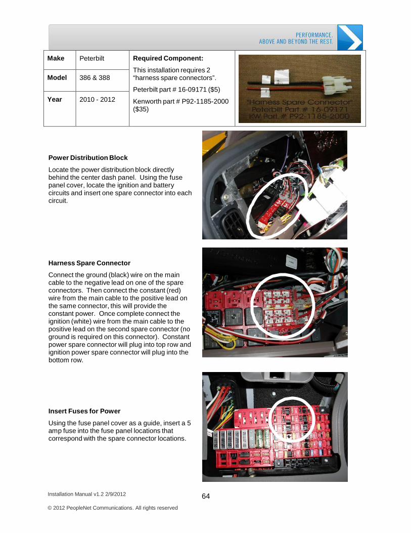
Peterbilt
Required Component:
This installation requires 2 “harness spare connectors”.
Peterbilt part # 16-09171 ($5)
Kenworth part # P92-1185-2000 ($35)
Model
386 & 388
Year
2010 - 2012
Power Distribution Block
Locate the power distribution block directly behind the center dash panel. Using the fuse panel cover, locate the ignition and battery circuits and insert one spare connector into each circuit.
Harness Spare Connector
Connect the ground (black) wire on the main cable to the negative lead on one of the spare connectors. Then connect the constant (red) wire from the main cable to the positive lead on the same connector, this will provide the constant power. Once complete connect the ignition (white) wire from the main cable to the positive lead on the second spare connector (no ground is required on this connector). Constant power spare connector will plug into top row and ignition power spare connector will plug into the bottom row.
Insert Fuses for Power
Using the fuse panel cover as a guide, insert a 5 amp fuse into the fuse panel locations that correspond with the spare connector locations.
Installation Manual v1.2 2/9/2012 65 © 2012 PeopleNet Communications. All rights reserved
OBC Installation: Power Connections
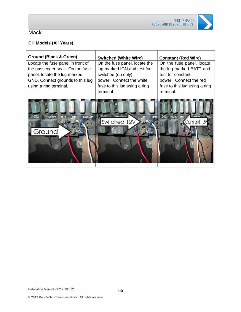
Mack
CH Models (All Years)
Ground (Black & Green)
Switched (White Wire)
Constant (Red Wire)
Locate the fuse panel in front of the passenger seat. On the fuse panel, locate the lug marked GND. Connect grounds to this lug using a ring terminal.
On the fuse panel, locate the lug marked IGN and test for switched (on only) power. Connect the white fuse to this lug using a ring terminal.
On the fuse panel, locate the lug marked BATT and test for constant power. Connect the red fuse to this lug using a ring terminal.
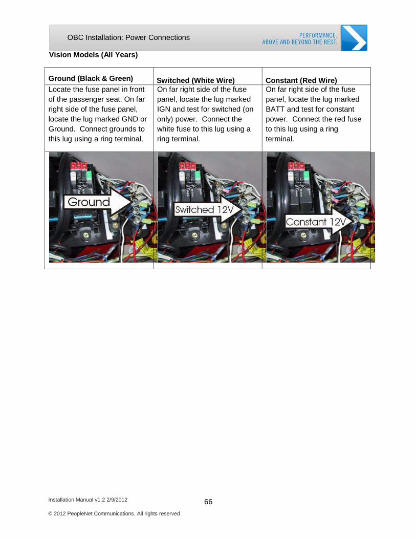
Installation Manual v1.2 2/9/2012 66 © 2012 PeopleNet Communications. All rights reserved
OBC Installation: Power Connections
Vision Models (All Years)
Ground (Black & Green)
Switched (White Wire)
Constant (Red Wire)
Locate the fuse panel in front of the passenger seat. On far right side of the fuse panel, locate the lug marked GND or Ground. Connect grounds to this lug using a ring terminal.
On far right side of the fuse panel, locate the lug marked IGN and test for switched (on only) power. Connect the white fuse to this lug using a ring terminal.
On far right side of the fuse panel, locate the lug marked BATT and test for constant power. Connect the red fuse to this lug using a ring terminal.
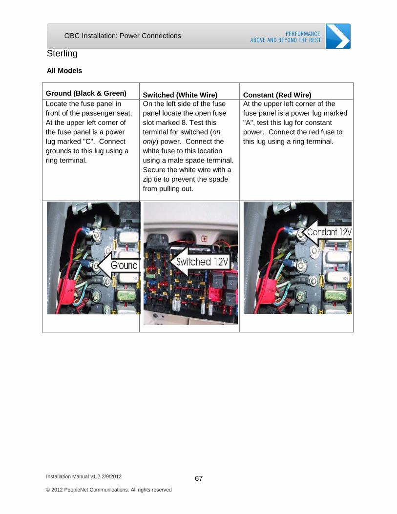
Installation Manual v1.2 2/9/2012 67 © 2012 PeopleNet Communications. All rights reserved
OBC Installation: Power Connections
Sterling
All Models
Ground (Black & Green)
Switched (White Wire)
Constant (Red Wire)
Locate the fuse panel in front of the passenger seat. At the upper left corner of the fuse panel is a power lug marked "C". Connect grounds to this lug using a ring terminal.
On the left side of the fuse panel locate the open fuse slot marked 8. Test this terminal for switched (on only) power. Connect the white fuse to this location using a male spade terminal. Secure the white wire with a zip tie to prevent the spade from pulling out.
At the upper left corner of the fuse panel is a power lug marked "A", test this lug for constant power. Connect the red fuse to this lug using a ring terminal.
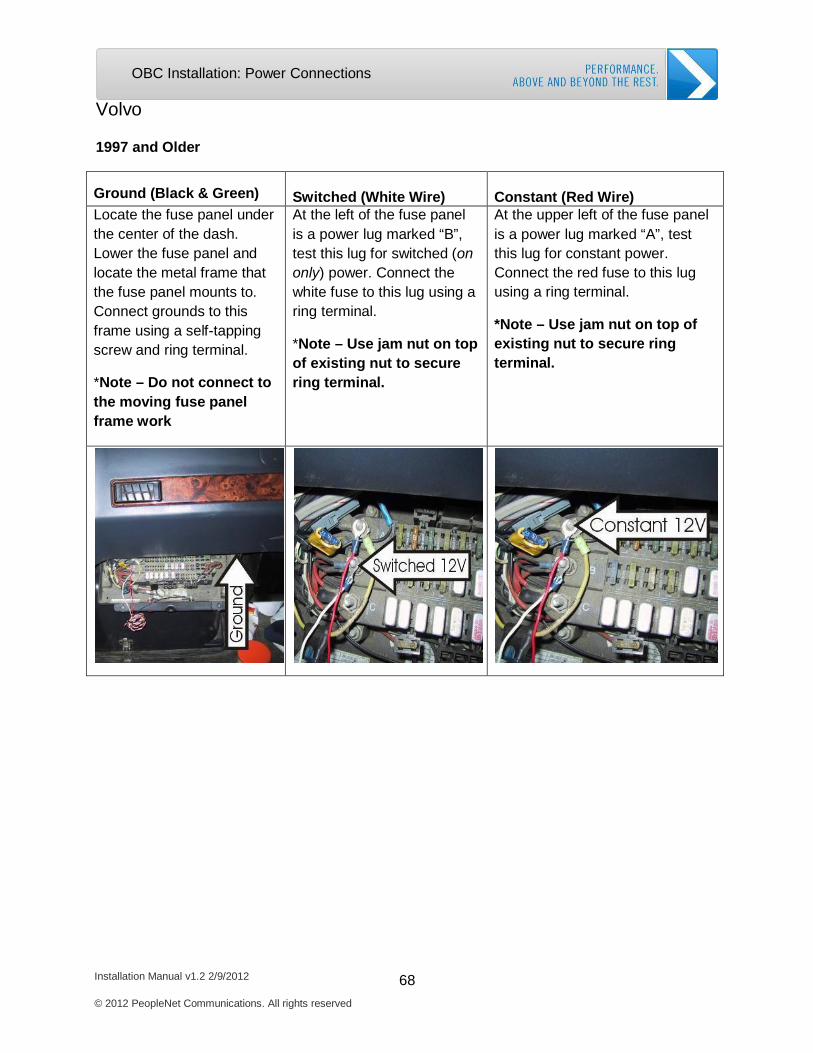
Installation Manual v1.2 2/9/2012 68 © 2012 PeopleNet Communications. All rights reserved
OBC Installation: Power Connections
Volvo
1997 and Older
Ground (Black & Green)
Switched (White Wire)
Constant (Red Wire)
Locate the fuse panel under the center of the dash. Lower the fuse panel and locate the metal frame that the fuse panel mounts to. Connect grounds to this frame using a self-tapping screw and ring terminal.
*Note – Do not connect to the moving fuse panel frame work
At the left of the fuse panel is a power lug marked “B”, test this lug for switched (on only) power. Connect the white fuse to this lug using a ring terminal.
*Note – Use jam nut on top of existing nut to secure ring terminal.
At the upper left of the fuse panel is a power lug marked “A”, test this lug for constant power. Connect the red fuse to this lug using a ring terminal.
*Note – Use jam nut on top of existing nut to secure ring terminal.
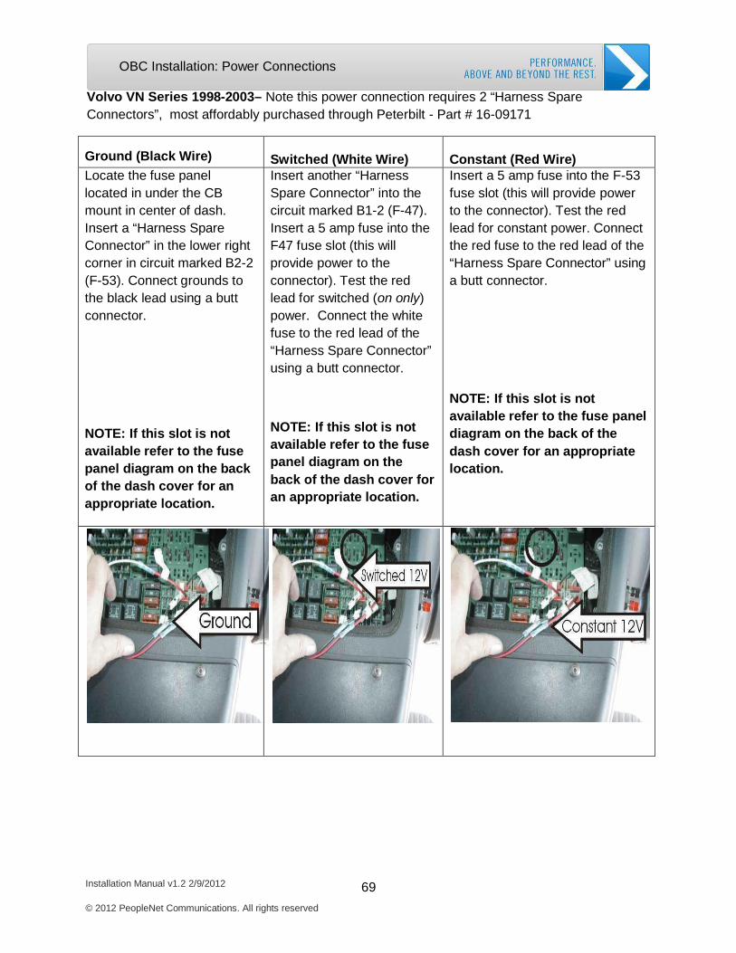
Installation Manual v1.2 2/9/2012 69 © 2012 PeopleNet Communications. All rights reserved
OBC Installation: Power Connections
Volvo VN Series 1998-2003– Note this power connection requires 2 “Harness Spare Connectors”, most affordably purchased through Peterbilt - Part # 16-09171
Ground (Black Wire)
Switched (White Wire)
Constant (Red Wire)
Locate the fuse panel located in under the CB mount in center of dash. Insert a “Harness Spare Connector” in the lower right corner in circuit marked B2-2 (F-53). Connect grounds to the black lead using a butt connector.
NOTE: If this slot is not available refer to the fuse panel diagram on the back of the dash cover for an appropriate location.
Insert another “Harness Spare Connector” into the circuit marked B1-2 (F-47). Insert a 5 amp fuse into the F47 fuse slot (this will provide power to the connector). Test the red lead for switched (on only) power. Connect the white fuse to the red lead of the “Harness Spare Connector” using a butt connector.
NOTE: If this slot is not available refer to the fuse panel diagram on the back of the dash cover for an appropriate location.
Insert a 5 amp fuse into the F-53 fuse slot (this will provide power to the connector). Test the red lead for constant power. Connect the red fuse to the red lead of the “Harness Spare Connector” using a butt connector.
NOTE: If this slot is not available refer to the fuse panel diagram on the back of the dash cover for an appropriate location.
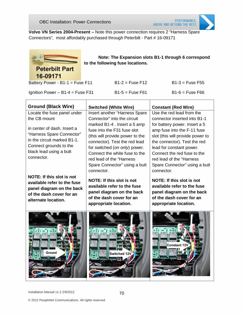
Installation Manual v1.2 2/9/2012 70 © 2012 PeopleNet Communications. All rights reserved
OBC Installation: Power Connections
B1-2 = Fuse F12 B1-3 = Fuse F55
B1-5 = Fuse F61
B1-6 = Fuse F66
Volvo VN Series 2004-Present – Note this power connection requires 2 “Harness Spare Connectors”, most affordably purchased through Peterbilt - Part # 16-09171
Note: The Expansion slots B1-1 through 6 correspond to the following fuse locations.
Battery Power - B1-1 = Fuse F11
Ignition Power – B1-4 = Fuse F31
Ground (Black Wire)
Switched (White Wire)
Constant (Red Wire)
Locate the fuse panel under the CB mount
in center of dash. Insert a “Harness Spare Connector” in the circuit marked B1-1. Connect grounds to the black lead using a butt connector.
NOTE: If this slot is not available refer to the fuse panel diagram on the back of the dash cover for an alternate location.
Insert another “Harness Spare Connector” into the circuit marked B1-4 . Insert a 5 amp fuse into the F31 fuse slot (this will provide power to the connector). Test the red lead for switched (on only) power. Connect the white fuse to the red lead of the “Harness Spare Connector” using a butt connector.
NOTE: If this slot is not available refer to the fuse panel diagram on the back of the dash cover for an appropriate location.
Use the red lead from the connector inserted into B1-1 for battery power. Insert a 5 amp fuse into the F-11 fuse slot (this will provide power to the connector). Test the red lead for constant power. Connect the red fuse to the red lead of the “Harness Spare Connector” using a butt connector.
NOTE: If this slot is not available refer to the fuse panel diagram on the back of the dash cover for an appropriate location.
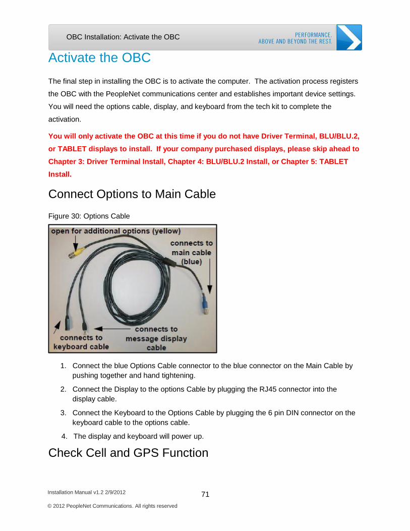
Installation Manual v1.2 2/9/2012 71 © 2012 PeopleNet Communications. All rights reserved
OBC Installation: Activate the OBC
Activate the OBC
The final step in installing the OBC is to activate the computer. The activation process registers
the OBC with the PeopleNet communications center and establishes important device settings.
You will need the options cable, display, and keyboard from the tech kit to complete the
activation.
You will only activate the OBC at this time if you do not have Driver Terminal, BLU/BLU.2, or TABLET displays to install. If your company purchased displays, please skip ahead to Chapter 3: Driver Terminal Install, Chapter 4: BLU/BLU.2 Install, or Chapter 5: TABLET Install.
Connect Options to Main Cable
Figure 30: Options Cable
1. Connect the blue Options Cable connector to the blue connector on the Main Cable by pushing together and hand tightening.
2. Connect the Display to the options Cable by plugging the RJ45 connector into the display cable.
3. Connect the Keyboard to the Options Cable by plugging the 6 pin DIN connector on the keyboard cable to the options cable.
4. The display and keyboard will power up.
Check Cell and GPS Function
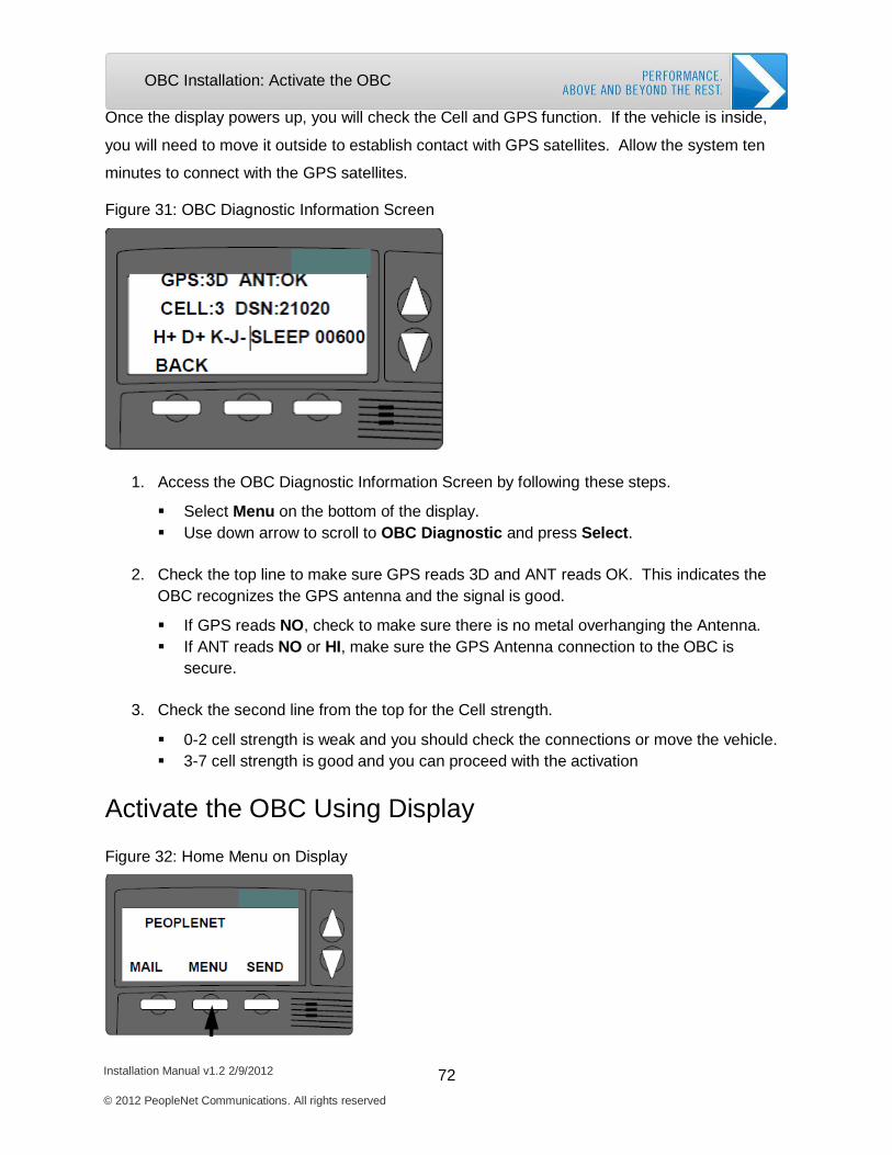
Installation Manual v1.2 2/9/2012 72 © 2012 PeopleNet Communications. All rights reserved
OBC Installation: Activate the OBC
Once the display powers up, you will check the Cell and GPS function. If the vehicle is inside,
you will need to move it outside to establish contact with GPS satellites. Allow the system ten
minutes to connect with the GPS satellites.
Figure 31: OBC Diagnostic Information Screen
1. Access the OBC Diagnostic Information Screen by following these steps.
Select Menu on the bottom of the display. Use down arrow to scroll to OBC Diagnostic and press Select.
2. Check the top line to make sure GPS reads 3D and ANT reads OK. This indicates the
OBC recognizes the GPS antenna and the signal is good.
If GPS reads NO, check to make sure there is no metal overhanging the Antenna. If ANT reads NO or HI, make sure the GPS Antenna connection to the OBC is
secure.
3. Check the second line from the top for the Cell strength.
0-2 cell strength is weak and you should check the connections or move the vehicle. 3-7 cell strength is good and you can proceed with the activation
Activate the OBC Using Display
Figure 32: Home Menu on Display
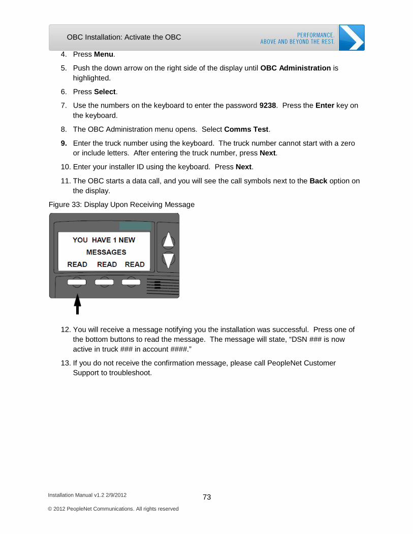
Installation Manual v1.2 2/9/2012 73 © 2012 PeopleNet Communications. All rights reserved
OBC Installation: Activate the OBC
4. Press Menu.
5. Push the down arrow on the right side of the display until OBC Administration is highlighted.
6. Press Select.
7. Use the numbers on the keyboard to enter the password 9238. Press the Enter key on the keyboard.
8. The OBC Administration menu opens. Select Comms Test.
9. Enter the truck number using the keyboard. The truck number cannot start with a zero or include letters. After entering the truck number, press Next.
10. Enter your installer ID using the keyboard. Press Next.
11. The OBC starts a data call, and you will see the call symbols next to the Back option on the display.
Figure 33: Display Upon Receiving Message
12. You will receive a message notifying you the installation was successful. Press one of the bottom buttons to read the message. The message will state, “DSN ### is now active in truck ### in account ####.”
13. If you do not receive the confirmation message, please call PeopleNet Customer Support to troubleshoot.
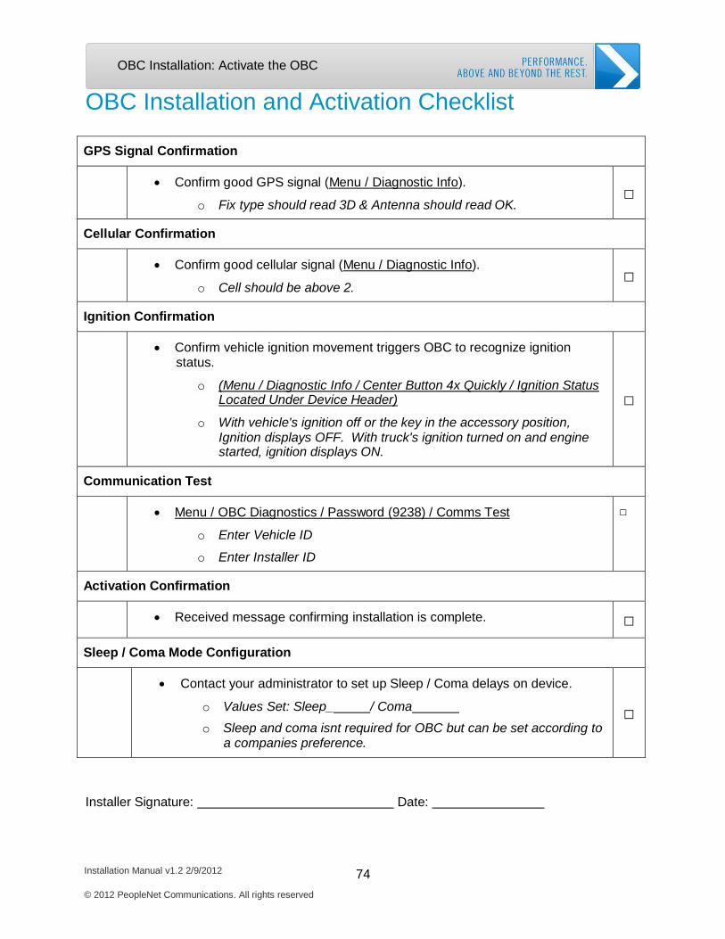
Installation Manual v1.2 2/9/2012 74 © 2012 PeopleNet Communications. All rights reserved
OBC Installation: Activate the OBC
OBC Installation and Activation Checklist
GPS Signal Confirmation
• Confirm good GPS signal (Menu / Diagnostic Info).
o Fix type should read 3D & Antenna should read OK.
□
Cellular Confirmation
• Confirm good cellular signal (Menu / Diagnostic Info).
o Cell should be above 2.
□
Ignition Confirmation
• Confirm vehicle ignition movement triggers OBC to recognize ignition status.
o (Menu / Diagnostic Info / Center Button 4x Quickly / Ignition Status Located Under Device Header)
o With vehicle's ignition off or the key in the accessory position, Ignition displays OFF. With truck's ignition turned on and engine started, ignition displays ON.
□
Communication Test
• Menu / OBC Diagnostics / Password (9238) / Comms Test
o Enter Vehicle ID
o Enter Installer ID
□
Activation Confirmation
• Received message confirming installation is complete.
□
Sleep / Coma Mode Configuration
• Contact your administrator to set up Sleep / Coma delays on device.
o Values Set: Sleep_ / Coma
o Sleep and coma isnt required for OBC but can be set according to a companies preference.
□
Installer Signature: Date:
3. Driver Terminal Installation
Required System Components
Install Option Cable
Install Driver Terminal
Install Keyboard
Activate System
Complete Installation Checklist
Installation Manual v1.2 2/9/2012 75
© 2012 PeopleNet Communications. All rights reserved

Driver Terminal Installation: System Components
Installation Manual v1.2 2/9/2012 76 © 2012 PeopleNet Communications. All rights reserved
Driver Terminal Required System Components
The Driver Terminal is an LCD (Liquid Crystal Display) that allows the driver to receive
messages in the cab. In additional to the driver terminal, you will most likely install a keyboard.
The keyboard is required for the driver to send messages and use several PeopleNet Value
Added Services, such as eDriver Logs. You will install three major hardware components in the
driver terminal installation.
Driver Terminal Display Keyboard Options Cable
The Driver Terminal is shipped as part of the Driver Terminal Kit. The kit includes the driver
terminal, options cable, and all the materials required for mounting the display. The Keyboard is
shipped as part of the Keyboard Kit. This kit includes the keyboard with a plastic cover
attached. You may also receive keyboard brackets to mount the keyboard in the vehicle.
Please compare the hardware kits received with the kits listed in Chapter 1.
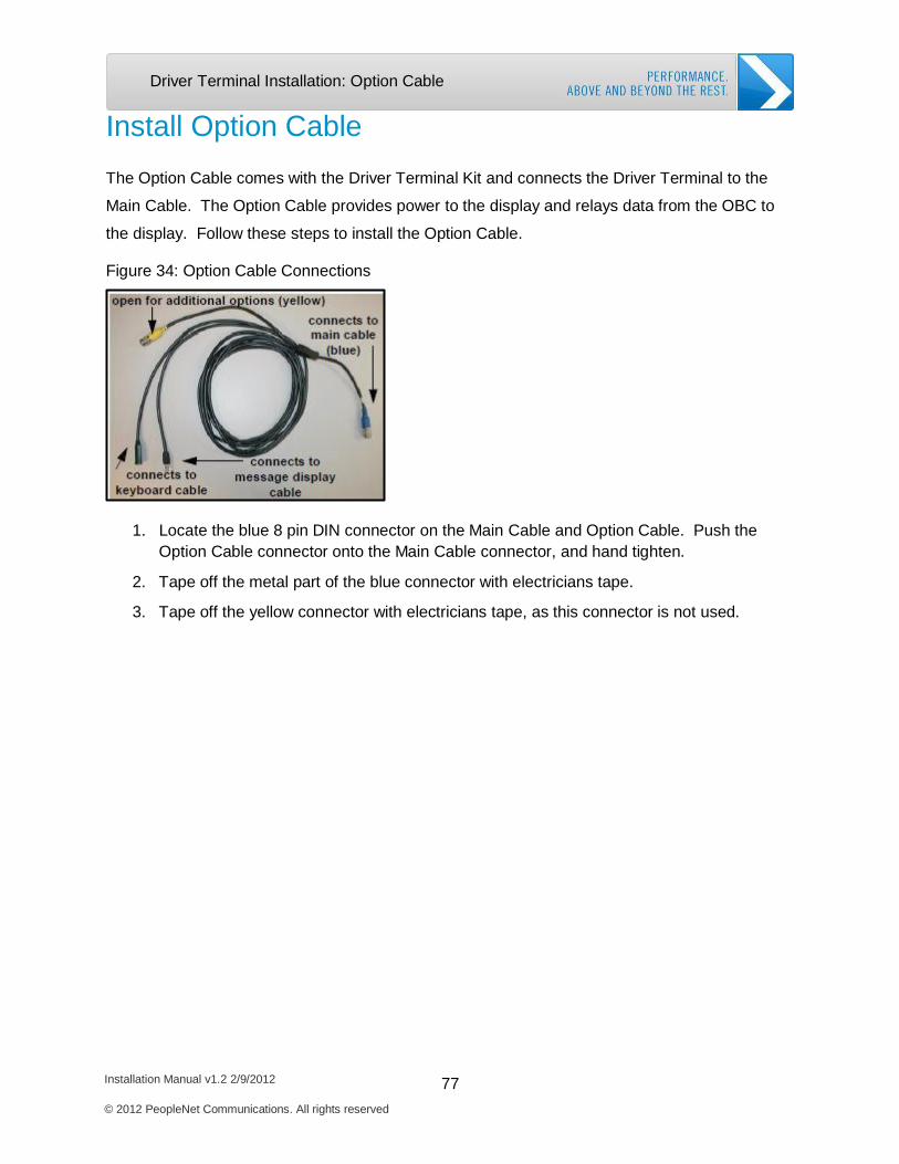
Installation Manual v1.2 2/9/2012 77 © 2012 PeopleNet Communications. All rights reserved
Driver Terminal Installation: Option Cable
Install Option Cable
The Option Cable comes with the Driver Terminal Kit and connects the Driver Terminal to the
Main Cable. The Option Cable provides power to the display and relays data from the OBC to
the display. Follow these steps to install the Option Cable.
Figure 34: Option Cable Connections
1. Locate the blue 8 pin DIN connector on the Main Cable and Option Cable. Push the Option Cable connector onto the Main Cable connector, and hand tighten.
2. Tape off the metal part of the blue connector with electricians tape.
3. Tape off the yellow connector with electricians tape, as this connector is not used.
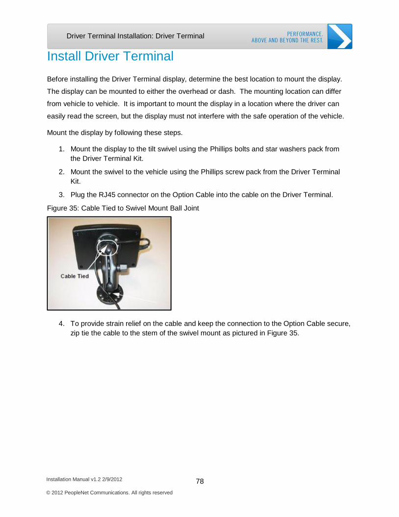
Installation Manual v1.2 2/9/2012 78 © 2012 PeopleNet Communications. All rights reserved
Driver Terminal Installation: Driver Terminal
Install Driver Terminal
Before installing the Driver Terminal display, determine the best location to mount the display.
The display can be mounted to either the overhead or dash. The mounting location can differ
from vehicle to vehicle. It is important to mount the display in a location where the driver can
easily read the screen, but the display must not interfere with the safe operation of the vehicle.
Mount the display by following these steps.
1. Mount the display to the tilt swivel using the Phillips bolts and star washers pack from the Driver Terminal Kit.
2. Mount the swivel to the vehicle using the Phillips screw pack from the Driver Terminal Kit.
3. Plug the RJ45 connector on the Option Cable into the cable on the Driver Terminal.
Figure 35: Cable Tied to Swivel Mount Ball Joint
4. To provide strain relief on the cable and keep the connection to the Option Cable secure, zip tie the cable to the stem of the swivel mount as pictured in Figure 35.
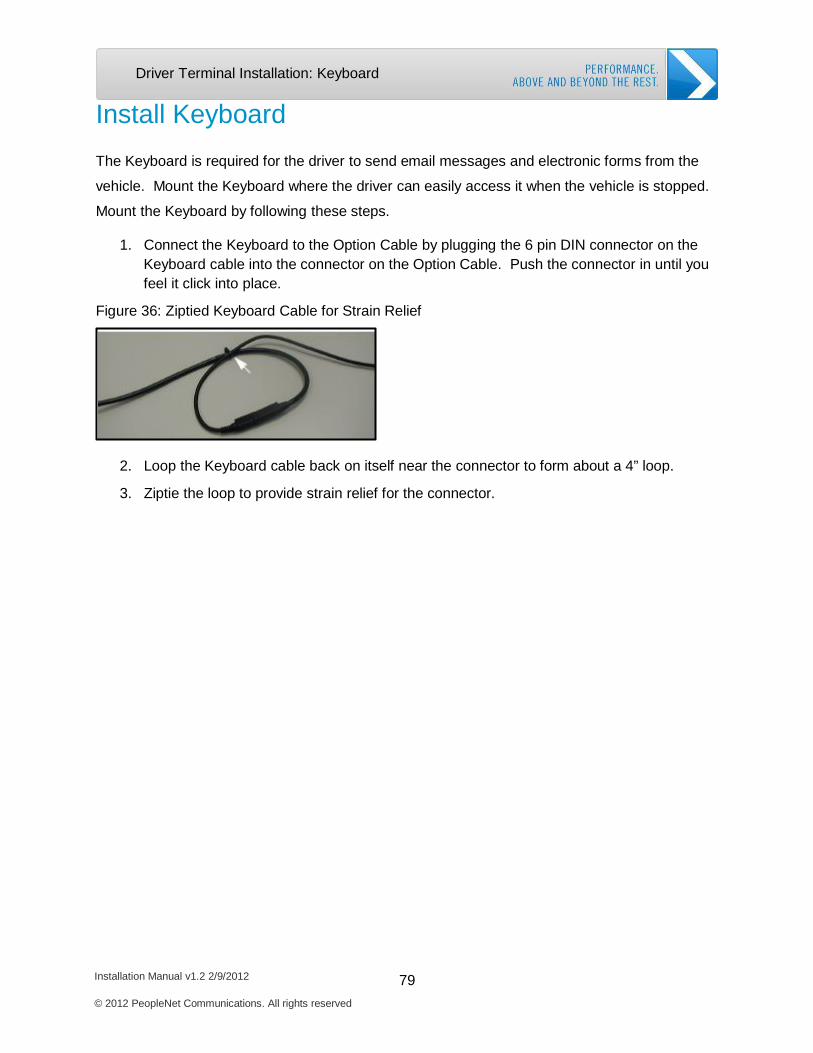
Installation Manual v1.2 2/9/2012 79 © 2012 PeopleNet Communications. All rights reserved
Driver Terminal Installation: Keyboard
Install Keyboard
The Keyboard is required for the driver to send email messages and electronic forms from the
vehicle. Mount the Keyboard where the driver can easily access it when the vehicle is stopped.
Mount the Keyboard by following these steps.
1. Connect the Keyboard to the Option Cable by plugging the 6 pin DIN connector on the Keyboard cable into the connector on the Option Cable. Push the connector in until you feel it click into place.
Figure 36: Ziptied Keyboard Cable for Strain Relief
2. Loop the Keyboard cable back on itself near the connector to form about a 4” loop.
3. Ziptie the loop to provide strain relief for the connector.
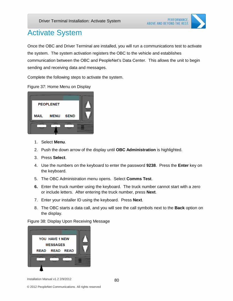
Installation Manual v1.2 2/9/2012 80 © 2012 PeopleNet Communications. All rights reserved
Driver Terminal Installation: Activate System
Activate System
Once the OBC and Driver Terminal are installed, you will run a communications test to activate
the system. The system activation registers the OBC to the vehicle and establishes
communication between the OBC and PeopleNet’s Data Center. This allows the unit to begin
sending and receiving data and messages.
Complete the following steps to activate the system.
Figure 37: Home Menu on Display
1. Select Menu.
2. Push the down arrow of the display until OBC Administration is highlighted.
3. Press Select.
4. Use the numbers on the keyboard to enter the password 9238. Press the Enter key on the keyboard.
5. The OBC Administration menu opens. Select Comms Test.
6. Enter the truck number using the keyboard. The truck number cannot start with a zero or include letters. After entering the truck number, press Next.
7. Enter your installer ID using the keyboard. Press Next.
8. The OBC starts a data call, and you will see the call symbols next to the Back option on the display.
Figure 38: Display Upon Receiving Message

Installation Manual v1.2 2/9/2012 81 © 2012 PeopleNet Communications. All rights reserved
Driver Terminal Installation: Activate System
9. You will receive a message notifying you of the successful installation. Press one of the bottom buttons to read the message. The message will state, “DSN ### is now active in truck ### in account ####.”
10. If you do not receive the confirmation message, please call PeopleNet Customer Support to troubleshoot.
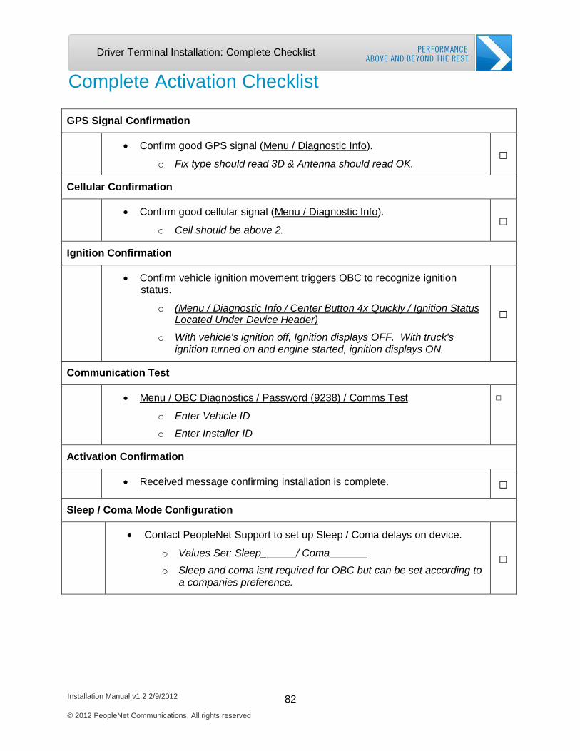
Installation Manual v1.2 2/9/2012 82 © 2012 PeopleNet Communications. All rights reserved
Driver Terminal Installation: Complete Checklist
Complete Activation Checklist
GPS Signal Confirmation
• Confirm good GPS signal (Menu / Diagnostic Info).
o Fix type should read 3D & Antenna should read OK.
□
Cellular Confirmation
• Confirm good cellular signal (Menu / Diagnostic Info).
o Cell should be above 2.
□
Ignition Confirmation
• Confirm vehicle ignition movement triggers OBC to recognize ignition status.
o (Menu / Diagnostic Info / Center Button 4x Quickly / Ignition Status Located Under Device Header)
o With vehicle's ignition off, Ignition displays OFF. With truck's ignition turned on and engine started, ignition displays ON.
□
Communication Test
• Menu / OBC Diagnostics / Password (9238) / Comms Test
o Enter Vehicle ID
o Enter Installer ID
□
Activation Confirmation
• Received message confirming installation is complete.
□
Sleep / Coma Mode Configuration
• Contact PeopleNet Support to set up Sleep / Coma delays on device.
o Values Set: Sleep_ / Coma
o Sleep and coma isnt required for OBC but can be set according to a companies preference.
□
4. BLU Installation
Required System Components
Mount BLU
Install DC to DC Converter
Complete OBC Firmware Download
Complete BLU Activation
Complete Installation Checklist
Installation Manual v1.2 2/9/2012 83
© 2012 PeopleNet Communications. All rights reserved
BLU Installation: Required Components
Installation Manual v1.2 2/9/2012 84 © 2012 PeopleNet Communications. All rights reserved
BLU Installation
BLU Required System Components
Before starting the BLU installation, complete the OBC installation following the directions in
Chapter 2.
The PeopleNet BLU is a touch screen display that allows the driver to receive and send
messages in the vehicle. Each BLU display is shipped with a BLU Installation Kit and DC to DC
Converter Kit. You will need each of these kits to properly complete the BLU install. The kits
include all the parts required to mount and install the BLU. Please compare the parts and kits
you received with the kits in Chapter 1. To complete the BLU installation, you will need the
following kits and supplies.
BLU Display Kit BLU Installation Kit DC to DC Converter Kit BLU Keyboard Kit (optional) Zip ties Four screws to mount the DC to DC converter 1 butt connector Electrical Tape
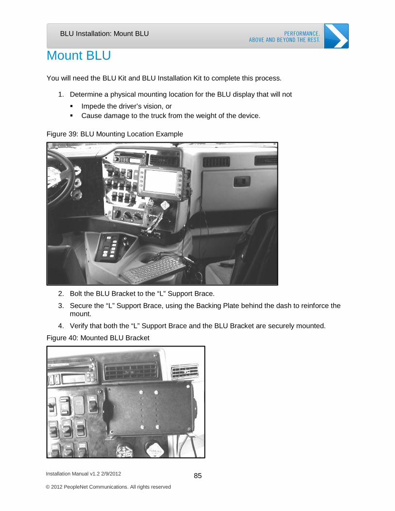
Installation Manual v1.2 2/9/2012 85 © 2012 PeopleNet Communications. All rights reserved
BLU Installation: Mount BLU
Mount BLU
You will need the BLU Kit and BLU Installation Kit to complete this process.
1. Determine a physical mounting location for the BLU display that will not
Impede the driver’s vision, or Cause damage to the truck from the weight of the device.
Figure 39: BLU Mounting Location Example
2. Bolt the BLU Bracket to the “L” Support Brace.
3. Secure the “L” Support Brace, using the Backing Plate behind the dash to reinforce the mount.
4. Verify that both the “L” Support Brace and the BLU Bracket are securely mounted.
Figure 40: Mounted BLU Bracket

Installation Manual v1.2 2/9/2012 86 © 2012 PeopleNet Communications. All rights reserved
BLU Installation: Mount BLU
5. Place the BLU display into the BLU Bracket.
6. Lock the BLU display in place with the Thumb Screws.
The BLU display is now mounted.
Do not connect the BLU display to the BLU Option Cable at this time. You must complete the
DC to DC Converter installation, before you connect the BLU display to the BLU Option Cable.

Installation Manual v1.2 2/9/2012 87 © 2012 PeopleNet Communications. All rights reserved
BLU Installation: Install DC to DC Converter
Install DC to DC Converter
The DC to DC Converter provides the BLU display with power. In addition, the DC to DC
Converter protects the BLU against the power fluctuations that often occur in vehicles. Proper
install of the DC to DC converter, ensures the BLU display operates safely and properly. You
will need the DC to DC Converter Kit to complete the following procedures.
Connect the DC to DC Power Converter to the PeopleNet
System
1. Locate the blue barrel connectors on the Main Cable and the BLU Option Cable.
2. Plug both connectors into their corresponding connectors on the DC-DC Power Supply.
3. Use pliers to gently tighten the connectors until snug.
Figure 41: Connect Main Cable blue Connector and BLU Options Cable Connector to DC to DC Converter
Mount the DC to DC Converter
1. Determine a location for the DC to DC Power Supply that meets the following requirements:
Safe from electrical contacts. Since the DC to DC Converter box is metal and connected directly to ground, it MUST NOT come into contact with a positive power
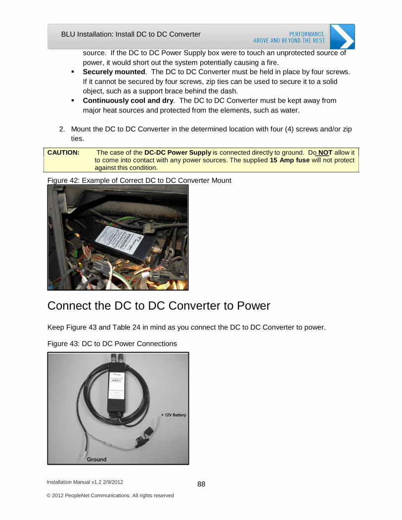
Installation Manual v1.2 2/9/2012 88 © 2012 PeopleNet Communications. All rights reserved
BLU Installation: Install DC to DC Converter
source. If the DC to DC Power Supply box were to touch an unprotected source of power, it would short out the system potentially causing a fire.
Securely mounted. The DC to DC Converter must be held in place by four screws. If it cannot be secured by four screws, zip ties can be used to secure it to a solid object, such as a support brace behind the dash.
Continuously cool and dry. The DC to DC Converter must be kept away from major heat sources and protected from the elements, such as water.
2. Mount the DC to DC Converter in the determined location with four (4) screws and/or zip
ties.
CAUTION: The case of the DC-DC Power Supply is connected directly to ground. Do NOT allow it to come into contact with any power sources. The supplied 15 Amp fuse will not protect against this condition.
Figure 42: Example of Correct DC to DC Converter Mount
Connect the DC to DC Converter to Power
Keep Figure 43 and Table 24 in mind as you connect the DC to DC Converter to power.
Figure 43: DC to DC Power Connections
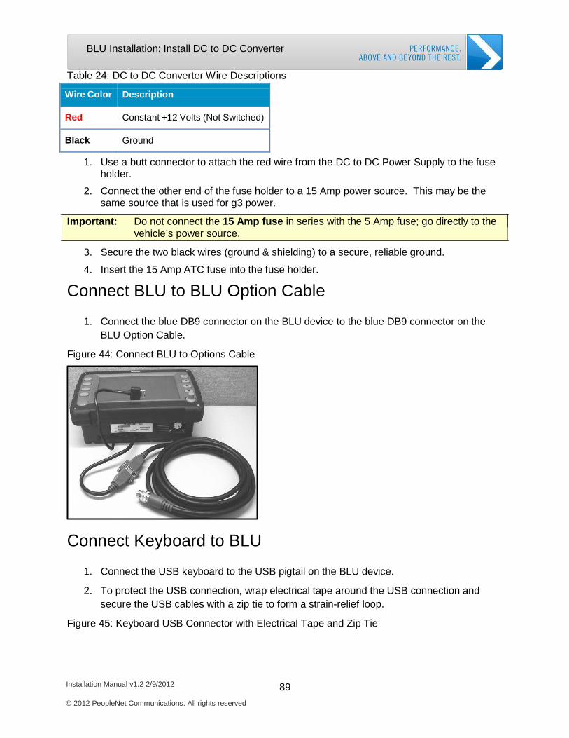
Installation Manual v1.2 2/9/2012 89 © 2012 PeopleNet Communications. All rights reserved
BLU Installation: Install DC to DC Converter
Table 24: DC to DC Converter Wire Descriptions
Wire Color
Description
Red
Constant +12 Volts (Not Switched)
Black
Ground
1. Use a butt connector to attach the red wire from the DC to DC Power Supply to the fuse holder.
2. Connect the other end of the fuse holder to a 15 Amp power source. This may be the same source that is used for g3 power.
Important: Do not connect the 15 Amp fuse in series with the 5 Amp fuse; go directly to the vehicle’s power source.
3. Secure the two black wires (ground & shielding) to a secure, reliable ground.
4. Insert the 15 Amp ATC fuse into the fuse holder.
Connect BLU to BLU Option Cable
1. Connect the blue DB9 connector on the BLU device to the blue DB9 connector on the BLU Option Cable.
Figure 44: Connect BLU to Options Cable
Connect Keyboard to BLU
1. Connect the USB keyboard to the USB pigtail on the BLU device.
2. To protect the USB connection, wrap electrical tape around the USB connection and secure the USB cables with a zip tie to form a strain-relief loop.
Figure 45: Keyboard USB Connector with Electrical Tape and Zip Tie
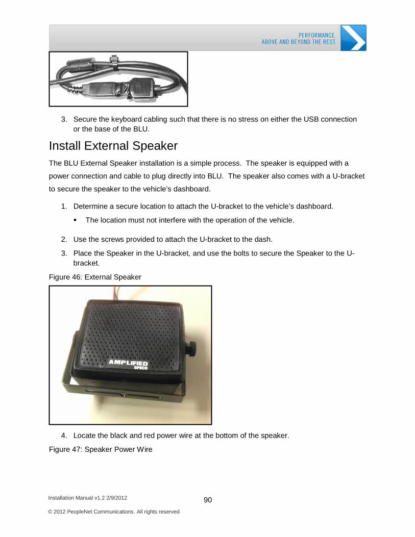
Installation Manual v1.2 2/9/2012 90 © 2012 PeopleNet Communications. All rights reserved
BLU Installation: Install DC to DC Converter
3. Secure the keyboard cabling such that there is no stress on either the USB connection or the base of the BLU.
Install External Speaker
The BLU External Speaker installation is a simple process. The speaker is equipped with a
power connection and cable to plug directly into BLU. The speaker also comes with a U-bracket
to secure the speaker to the vehicle’s dashboard.
1. Determine a secure location to attach the U-bracket to the vehicle’s dashboard.
The location must not interfere with the operation of the vehicle.
2. Use the screws provided to attach the U-bracket to the dash.
3. Place the Speaker in the U-bracket, and use the bolts to secure the Speaker to the U-
bracket.
Figure 46: External Speaker
4. Locate the black and red power wire at the bottom of the speaker.
Figure 47: Speaker Power Wire
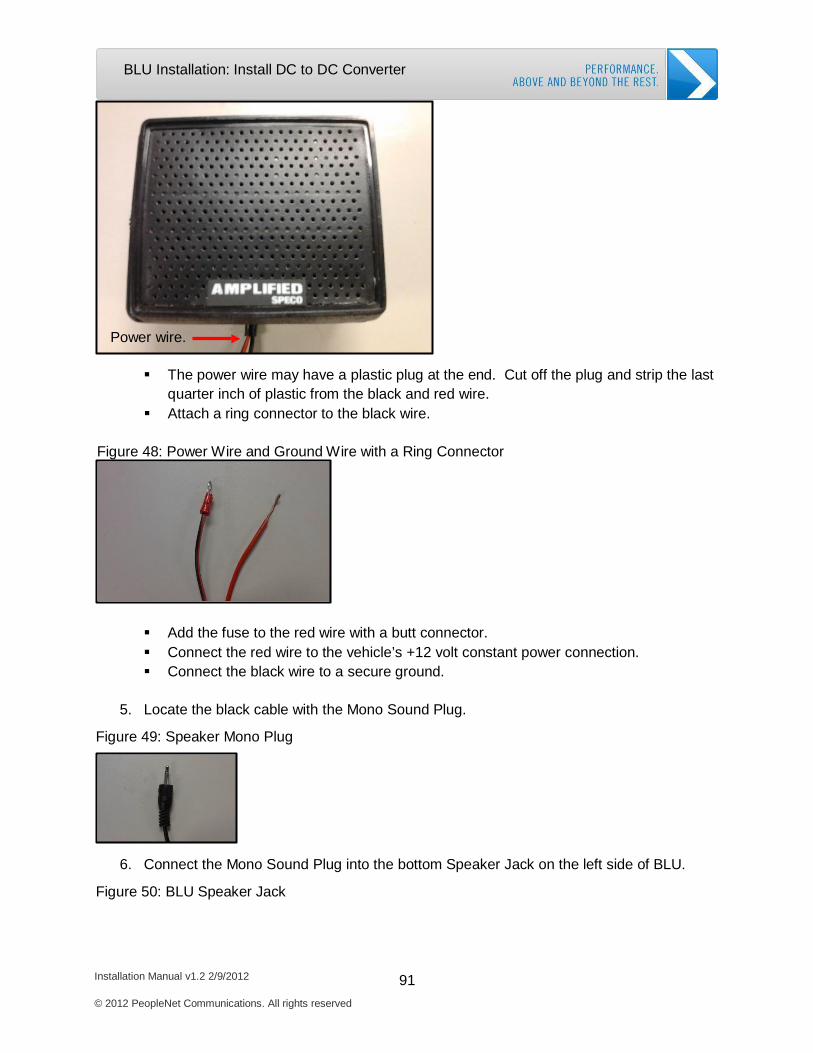
Installation Manual v1.2 2/9/2012 91 © 2012 PeopleNet Communications. All rights reserved
BLU Installation: Install DC to DC Converter
Power wire.
The power wire may have a plastic plug at the end. Cut off the plug and strip the last
quarter inch of plastic from the black and red wire. Attach a ring connector to the black wire.
Figure 48: Power Wire and Ground Wire with a Ring Connector
Add the fuse to the red wire with a butt connector. Connect the red wire to the vehicle’s +12 volt constant power connection. Connect the black wire to a secure ground.
5. Locate the black cable with the Mono Sound Plug.
Figure 49: Speaker Mono Plug
6. Connect the Mono Sound Plug into the bottom Speaker Jack on the left side of BLU.
Figure 50: BLU Speaker Jack
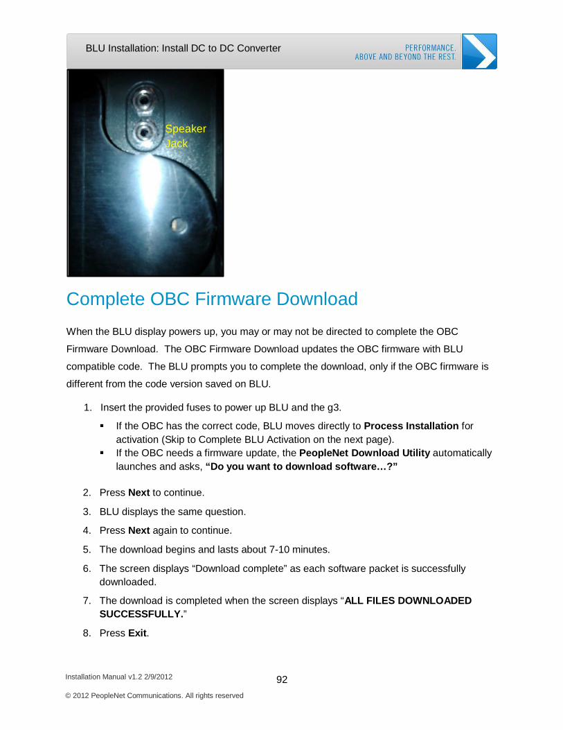
Installation Manual v1.2 2/9/2012 92 © 2012 PeopleNet Communications. All rights reserved
BLU Installation: Install DC to DC Converter
Speaker Jack
Complete OBC Firmware Download
When the BLU display powers up, you may or may not be directed to complete the OBC
Firmware Download. The OBC Firmware Download updates the OBC firmware with BLU
compatible code. The BLU prompts you to complete the download, only if the OBC firmware is
different from the code version saved on BLU.
1. Insert the provided fuses to power up BLU and the g3.
If the OBC has the correct code, BLU moves directly to Process Installation for activation (Skip to Complete BLU Activation on the next page).
If the OBC needs a firmware update, the PeopleNet Download Utility automatically launches and asks, “Do you want to download software…?”
2. Press Next to continue.
3. BLU displays the same question.
4. Press Next again to continue.
5. The download begins and lasts about 7-10 minutes.
6. The screen displays “Download complete” as each software packet is successfully
downloaded.
7. The download is completed when the screen displays “ALL FILES DOWNLOADED SUCCESSFULLY.”
8. Press Exit.
Installation Manual v1.2 2/9/2012 93 © 2012 PeopleNet Communications. All rights reserved
BLU Installation: Complete BLU Activation
Complete BLU Activation
The BLU activation process synchronizes the BLU to the OBC and activates both the OBC and
BLU on the PeopleNet System.
1. BLU displays “Would you like to process an installation?”. Select Yes.
2. BLU displays “Is this a new installation?”. Select Yes.
3. The BLU displays the next installation screen requesting your Installer ID, Truck Number, and DSN Number (device serial number).
a. Enter your Installer ID in the text box labeled Installer ID. Press Tab.
b. Enter the Truck Number in the text box labeled Truck Number. Press Tab.
c. BLU displays the OBC DSN below the Submit button. Make sure the OBC DSN
matches the DSN in the vehicle.
4. Press Submit. BLU places a data call to complete activation.
a. If the 2nd green LED stops flashing and the screen has not changed, press Data Call to continue the installation.
5. The screen changes and displays a message confirming successful installation.
a. Once you receive the installation confirmation message, the BLU activation is
complete.
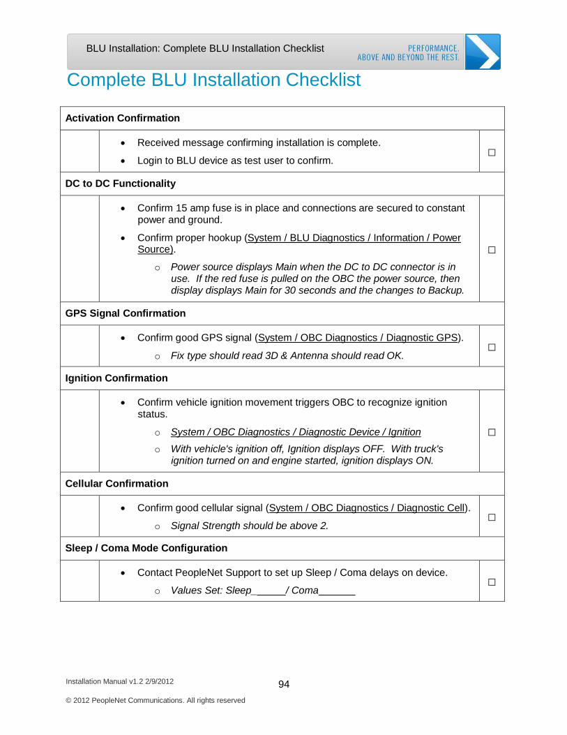
Installation Manual v1.2 2/9/2012 94 © 2012 PeopleNet Communications. All rights reserved
BLU Installation: Complete BLU Installation Checklist
Complete BLU Installation Checklist
Activation Confirmation
• Received message confirming installation is complete.
• Login to BLU device as test user to confirm.
□
DC to DC Functionality
• Confirm 15 amp fuse is in place and connections are secured to constant power and ground.
• Confirm proper hookup (System / BLU Diagnostics / Information / Power Source).
o Power source displays Main when the DC to DC connector is in use. If the red fuse is pulled on the OBC the power source, then display displays Main for 30 seconds and the changes to Backup.
□
GPS Signal Confirmation
• Confirm good GPS signal (System / OBC Diagnostics / Diagnostic GPS).
o Fix type should read 3D & Antenna should read OK.
□
Ignition Confirmation
• Confirm vehicle ignition movement triggers OBC to recognize ignition status.
o System / OBC Diagnostics / Diagnostic Device / Ignition
o With vehicle's ignition off, Ignition displays OFF. With truck's ignition turned on and engine started, ignition displays ON.
□
Cellular Confirmation
• Confirm good cellular signal (System / OBC Diagnostics / Diagnostic Cell).
o Signal Strength should be above 2.
□
Sleep / Coma Mode Configuration
• Contact PeopleNet Support to set up Sleep / Coma delays on device.
o Values Set: Sleep_ / Coma
□

5. TABLET Installation
Required System Components
Mount the Docking Station
Install DC to DC Converter
Complete OBC Firmware Download
Complete TABLET Activation
Complete Installation Checklist
Installation Manual v1.2 2/9/2012 95
© 2012 PeopleNet Communications. All rights reserved
TABLET Installation: Required Components
Installation Manual v1.2 2/9/2012 96 © 2012 PeopleNet Communications. All rights reserved
TABLET Installation
Required System Components
Before starting the TABLET installation, complete the OBC installation following the directions in
Chapter 2.
The PeopleNet TABLET is a portable touch screen display that allows the driver to message,
print, scan, and take pictures in and out of the vehicle. Each TABLET display is shipped with a
TABLET Dock Installation Kit and DC to DC Converter Kit. You will need each of these kits to
properly complete the install. The kits include all the parts required to mount and install the
TABLET. You also may install an optional TABLET Speaker Kit. Please compare the parts and
kits you received with the kits in Chapter 1. To complete the TABLET installation, you will need
the following kits and supplies.
TABLET Display Kit TABLET Dock Installation Kit TABLET DC to DC Converter Kit Keyboard (Optional) TABLET Speaker Kit (Optional) Zip Ties 4 screws to mount DC to DC Converter 1 butt connector for the DC to DC Converter Electrical Tape
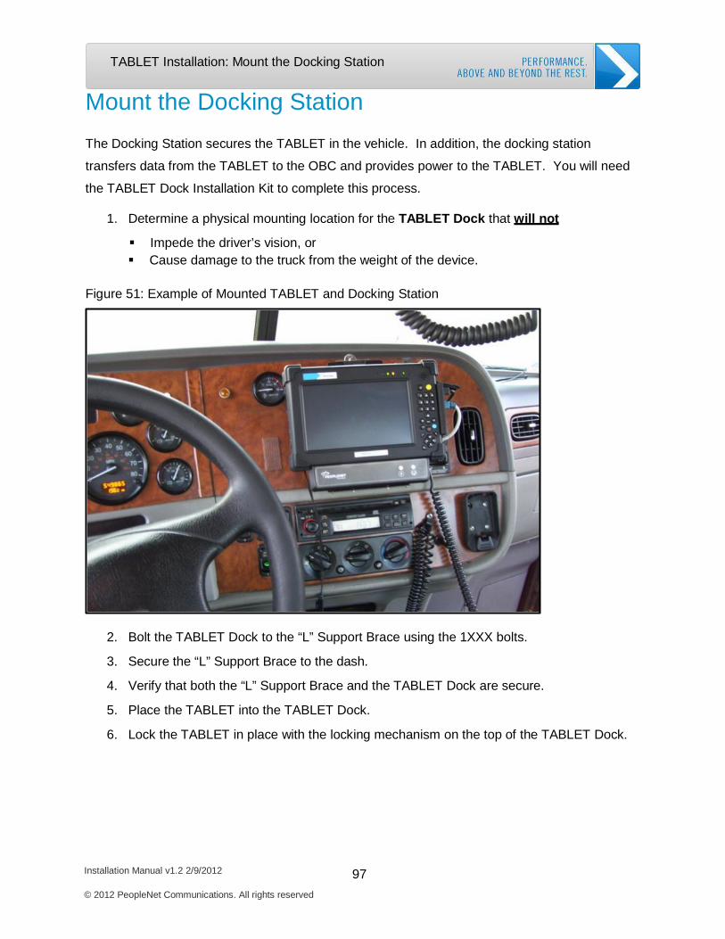
Installation Manual v1.2 2/9/2012 97 © 2012 PeopleNet Communications. All rights reserved
TABLET Installation: Mount the Docking Station
Mount the Docking Station
The Docking Station secures the TABLET in the vehicle. In addition, the docking station
transfers data from the TABLET to the OBC and provides power to the TABLET. You will need
the TABLET Dock Installation Kit to complete this process.
1. Determine a physical mounting location for the TABLET Dock that will not
Impede the driver’s vision, or Cause damage to the truck from the weight of the device.
Figure 51: Example of Mounted TABLET and Docking Station
2. Bolt the TABLET Dock to the “L” Support Brace using the 1XXX bolts.
3. Secure the “L” Support Brace to the dash.
4. Verify that both the “L” Support Brace and the TABLET Dock are secure.
5. Place the TABLET into the TABLET Dock.
6. Lock the TABLET in place with the locking mechanism on the top of the TABLET Dock.
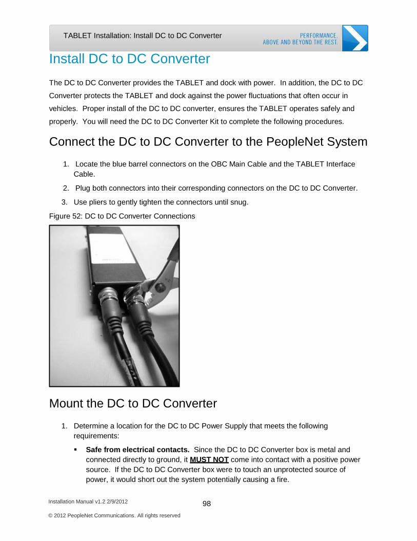
Installation Manual v1.2 2/9/2012 98 © 2012 PeopleNet Communications. All rights reserved
TABLET Installation: Install DC to DC Converter
Install DC to DC Converter
The DC to DC Converter provides the TABLET and dock with power. In addition, the DC to DC
Converter protects the TABLET and dock against the power fluctuations that often occur in
vehicles. Proper install of the DC to DC converter, ensures the TABLET operates safely and
properly. You will need the DC to DC Converter Kit to complete the following procedures.
Connect the DC to DC Converter to the PeopleNet System
1. Locate the blue barrel connectors on the OBC Main Cable and the TABLET Interface Cable.
2. Plug both connectors into their corresponding connectors on the DC to DC Converter.
3. Use pliers to gently tighten the connectors until snug.
Figure 52: DC to DC Converter Connections
Mount the DC to DC Converter
1. Determine a location for the DC to DC Power Supply that meets the following requirements:
Safe from electrical contacts. Since the DC to DC Converter box is metal and connected directly to ground, it MUST NOT come into contact with a positive power source. If the DC to DC Converter box were to touch an unprotected source of power, it would short out the system potentially causing a fire.
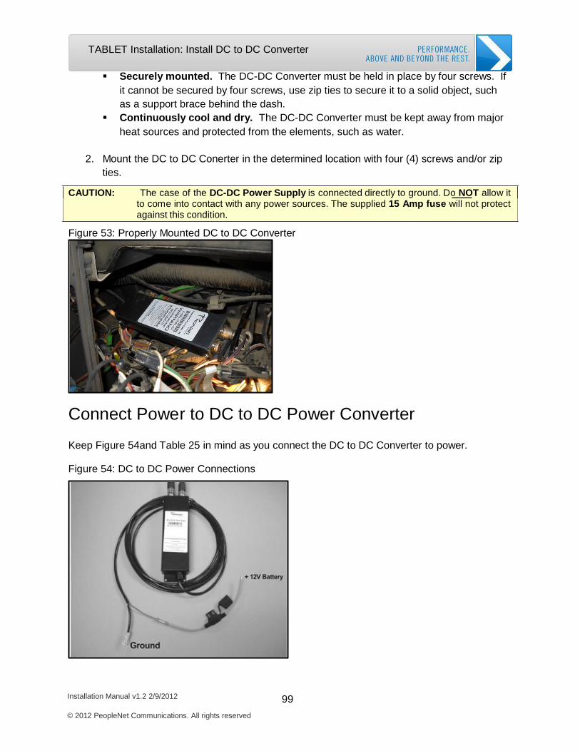
Installation Manual v1.2 2/9/2012 99 © 2012 PeopleNet Communications. All rights reserved
TABLET Installation: Install DC to DC Converter
Securely mounted. The DC-DC Converter must be held in place by four screws. If it cannot be secured by four screws, use zip ties to secure it to a solid object, such as a support brace behind the dash.
Continuously cool and dry. The DC-DC Converter must be kept away from major heat sources and protected from the elements, such as water.
2. Mount the DC to DC Conerter in the determined location with four (4) screws and/or zip
ties.
CAUTION: The case of the DC-DC Power Supply is connected directly to ground. Do NOT allow it to come into contact with any power sources. The supplied 15 Amp fuse will not protect against this condition.
Figure 53: Properly Mounted DC to DC Converter
Connect Power to DC to DC Power Converter
Keep Figure 54and Table 25 in mind as you connect the DC to DC Converter to power.
Figure 54: DC to DC Power Connections
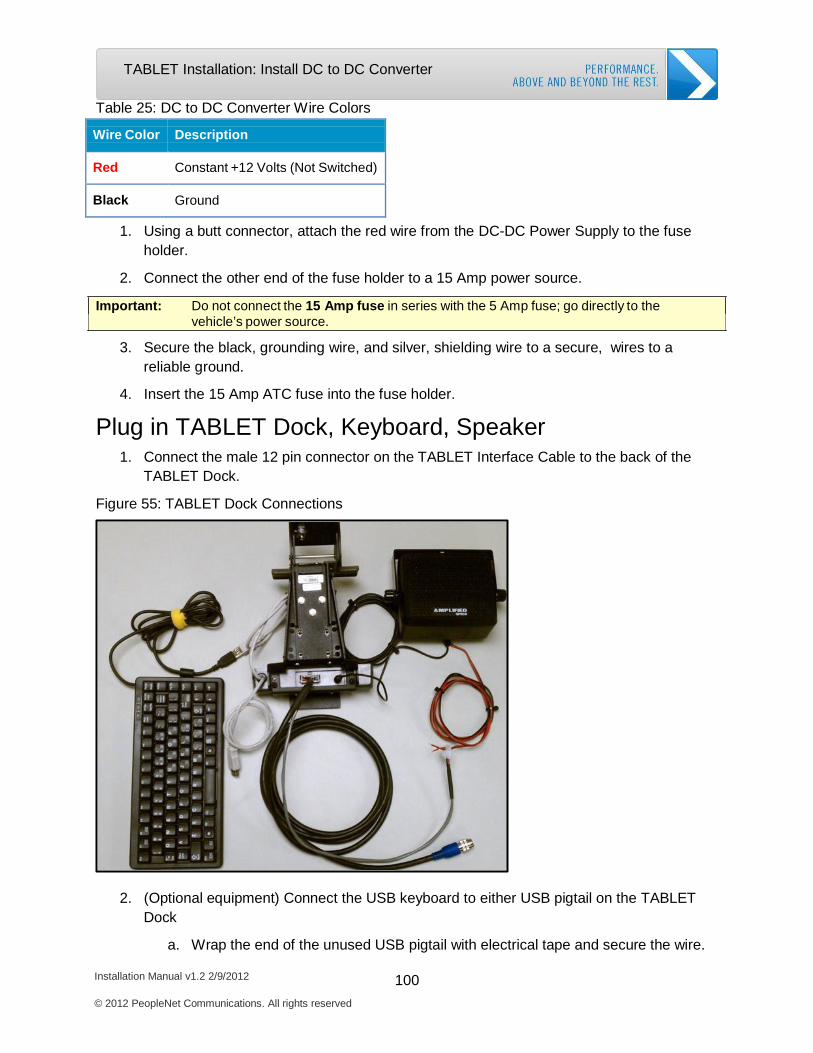
Installation Manual v1.2 2/9/2012 100 © 2012 PeopleNet Communications. All rights reserved
TABLET Installation: Install DC to DC Converter
Table 25: DC to DC Converter Wire Colors
Wire Color
Description
Red
Constant +12 Volts (Not Switched)
Black
Ground
1. Using a butt connector, attach the red wire from the DC-DC Power Supply to the fuse holder.
2. Connect the other end of the fuse holder to a 15 Amp power source.
Important: Do not connect the 15 Amp fuse in series with the 5 Amp fuse; go directly to the vehicle’s power source.
3. Secure the black, grounding wire, and silver, shielding wire to a secure, wires to a reliable ground.
4. Insert the 15 Amp ATC fuse into the fuse holder.
Plug in TABLET Dock, Keyboard, Speaker
1. Connect the male 12 pin connector on the TABLET Interface Cable to the back of the TABLET Dock.
Figure 55: TABLET Dock Connections
2. (Optional equipment) Connect the USB keyboard to either USB pigtail on the TABLET Dock
a. Wrap the end of the unused USB pigtail with electrical tape and secure the wire.
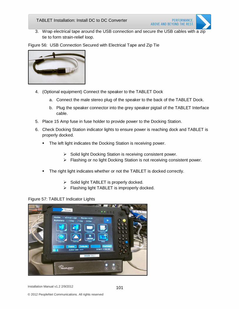
Installation Manual v1.2 2/9/2012 101 © 2012 PeopleNet Communications. All rights reserved
TABLET Installation: Install DC to DC Converter
3. Wrap electrical tape around the USB connection and secure the USB cables with a zip tie to form strain-relief loop.
Figure 56: USB Connection Secured with Electrical Tape and Zip Tie
4. (Optional equipment) Connect the speaker to the TABLET Dock
a. Connect the male stereo plug of the speaker to the back of the TABLET Dock.
b. Plug the speaker connector into the grey speaker pigtail of the TABLET Interface cable.
5. Place 15 Amp fuse in fuse holder to provide power to the Docking Station.
6. Check Docking Station indicator lights to ensure power is reaching dock and TABLET is properly docked.
The left light indicates the Docking Station is receiving power.
Solid light Docking Station is receiving consistent power. Flashing or no light Docking Station is not receiving consistent power.
The right light indicates whether or not the TABLET is docked correctly.
Solid light TABLET is properly docked. Flashing light TABLET is improperly docked.
Figure 57: TABLET Indicator Lights

Installation Manual v1.2 2/9/2012 102 © 2012 PeopleNet Communications. All rights reserved
TABLET Installation: OBC Firmware Download
OBC Firmware Download
When the TABLET powers up, you may or may not be directed to complete the OBC Firmware
Download. The OBC Firmware Download updates the OBC firmware with TABLET compatible
code. The TABLET prompts you to complete the download, only if the OBC firmware is different
from the code version saved on TABLET.
1. Insert the provided fuses to power up TABLET and the g3.
If the OBC has the correct code, TABLET will move directly to Process Installation. If the OBC needs a firmware update, the PeopleNet Download Utility automatically
launches and asks you, “….Would you like to update the OBC?”
2. Press Yes to continue.
a. The download begins and lasts about 7-10 minutes.
3. The screen displays “Download Complete” as each software packet is successfully downloaded.
4. The download is completed when the screen displays “OBC Upgrade Successful.”
5. Press “OK” and proceed to TABLET activation.

Installation Manual v1.2 2/9/2012 103 © 2012 PeopleNet Communications. All rights reserved
TABLET Installation: Complete TABLET Activation
Complete TABLET Activation
The TABLET activation process synchronizes the TABLET to the OBC and activates both the
OBC and TABLET on the PeopleNet System.
1. TABLET displays “Would you like to process an installation?”. Select Yes.
2. TABLET displays “Is this a new installation?”. If the OBC is brand new, select “Yes”. If the g3/OBC is currently active in the PFM (PeopleNet Feet Manager), select “No”.
3. Enter your Installer Number and press the Tab key.
4. Enter your Truck Number.
5. Press Submit.
If the 2nd green LED stops flashing and the screen has not changed, press Data Call to continue the installation.
The screen changes and displays a message confirming successful installation.
The TABLET activation is complete, once you receive the installation confirmation message.
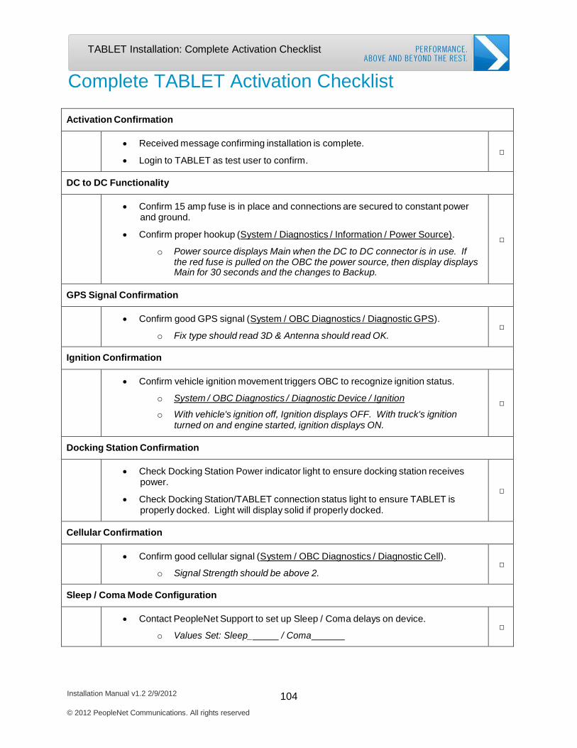
Installation Manual v1.2 2/9/2012 104 © 2012 PeopleNet Communications. All rights reserved
TABLET Installation: Complete Activation Checklist
Complete TABLET Activation Checklist
Activation Confirmation
• Received message confirming installation is complete.
• Login to TABLET as test user to confirm.
□
DC to DC Functionality
• Confirm 15 amp fuse is in place and connections are secured to constant power and ground.
• Confirm proper hookup (System / Diagnostics / Information / Power Source).
o Power source displays Main when the DC to DC connector is in use. If the red fuse is pulled on the OBC the power source, then display displays Main for 30 seconds and the changes to Backup.
□
GPS Signal Confirmation
• Confirm good GPS signal (System / OBC Diagnostics / Diagnostic GPS).
o Fix type should read 3D & Antenna should read OK.
□
Ignition Confirmation
• Confirm vehicle ignition movement triggers OBC to recognize ignition status.
o System / OBC Diagnostics / Diagnostic Device / Ignition
o With vehicle's ignition off, Ignition displays OFF. With truck's ignition turned on and engine started, ignition displays ON.
□
Docking Station Confirmation
• Check Docking Station Power indicator light to ensure docking station receives power.
• Check Docking Station/TABLET connection status light to ensure TABLET is properly docked. Light will display solid if properly docked.
□
Cellular Confirmation
• Confirm good cellular signal (System / OBC Diagnostics / Diagnostic Cell).
o Signal Strength should be above 2.
□
Sleep / Coma Mode Configuration
• Contact PeopleNet Support to set up Sleep / Coma delays on device.
o Values Set: Sleep_ / Coma
□

BLU.2 Installation
Required System Components
Mount the BLU.2
Install DC to DC Converter
Complete OBC Firmware Download
Complete BLU.2 Activation
Complete Installation Checklist
Installation Manual v1.2 2/9/2012
© 2012 PeopleNet Communications. All rights reserved
106
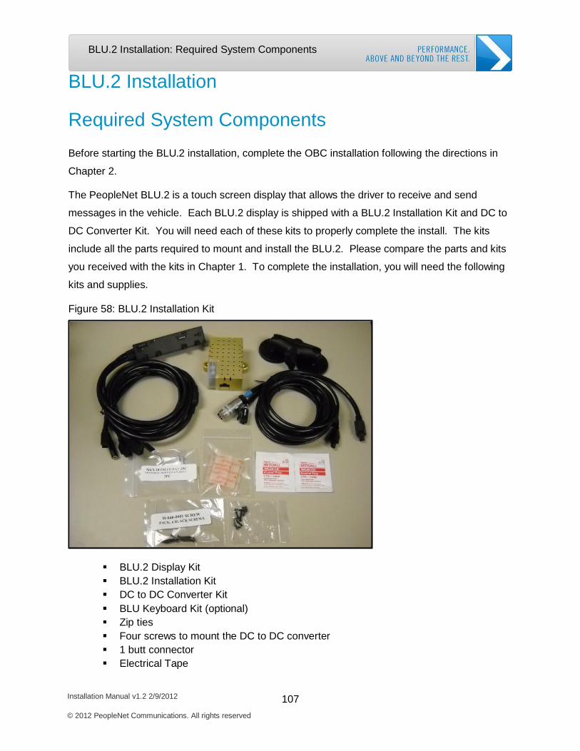
BLU.2 Installation: Required System Components
Installation Manual v1.2 2/9/2012 107 © 2012 PeopleNet Communications. All rights reserved
BLU.2 Installation
Required System Components
Before starting the BLU.2 installation, complete the OBC installation following the directions in
Chapter 2.
The PeopleNet BLU.2 is a touch screen display that allows the driver to receive and send
messages in the vehicle. Each BLU.2 display is shipped with a BLU.2 Installation Kit and DC to
DC Converter Kit. You will need each of these kits to properly complete the install. The kits
include all the parts required to mount and install the BLU.2. Please compare the parts and kits
you received with the kits in Chapter 1. To complete the installation, you will need the following
kits and supplies.
Figure 58: BLU.2 Installation Kit
BLU.2 Display Kit BLU.2 Installation Kit DC to DC Converter Kit BLU Keyboard Kit (optional) Zip ties Four screws to mount the DC to DC converter 1 butt connector Electrical Tape
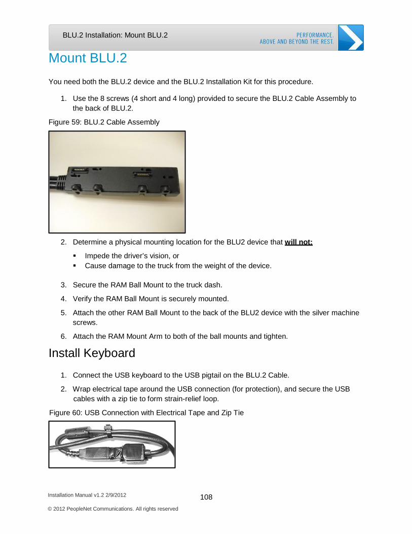
Installation Manual v1.2 2/9/2012 108 © 2012 PeopleNet Communications. All rights reserved
BLU.2 Installation: Mount BLU.2
Mount BLU.2
You need both the BLU.2 device and the BLU.2 Installation Kit for this procedure.
1. Use the 8 screws (4 short and 4 long) provided to secure the BLU.2 Cable Assembly to the back of BLU.2.
Figure 59: BLU.2 Cable Assembly
2. Determine a physical mounting location for the BLU2 device that will not:
Impede the driver’s vision, or Cause damage to the truck from the weight of the device.
3. Secure the RAM Ball Mount to the truck dash.
4. Verify the RAM Ball Mount is securely mounted.
5. Attach the other RAM Ball Mount to the back of the BLU2 device with the silver machine
screws.
6. Attach the RAM Mount Arm to both of the ball mounts and tighten.
Install Keyboard
1. Connect the USB keyboard to the USB pigtail on the BLU.2 Cable.
2. Wrap electrical tape around the USB connection (for protection), and secure the USB cables with a zip tie to form strain-relief loop.
Figure 60: USB Connection with Electrical Tape and Zip Tie
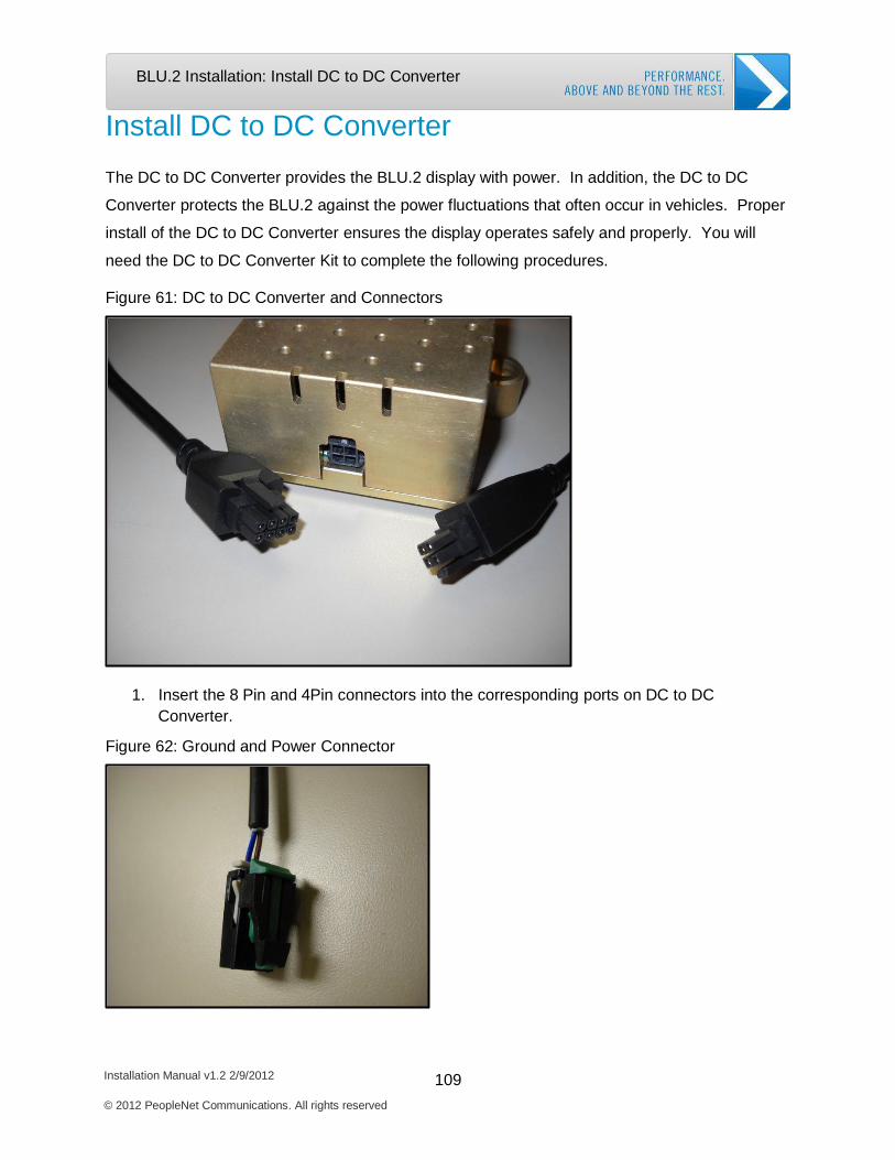
Installation Manual v1.2 2/9/2012 109 © 2012 PeopleNet Communications. All rights reserved
BLU.2 Installation: Install DC to DC Converter
Install DC to DC Converter
The DC to DC Converter provides the BLU.2 display with power. In addition, the DC to DC
Converter protects the BLU.2 against the power fluctuations that often occur in vehicles. Proper
install of the DC to DC Converter ensures the display operates safely and properly. You will
need the DC to DC Converter Kit to complete the following procedures.
Figure 61: DC to DC Converter and Connectors
1. Insert the 8 Pin and 4Pin connectors into the corresponding ports on DC to DC Converter.
Figure 62: Ground and Power Connector
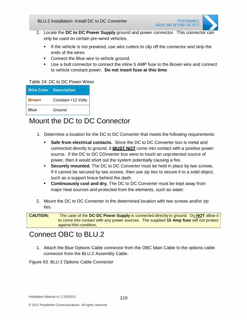
Installation Manual v1.2 2/9/2012 110 © 2012 PeopleNet Communications. All rights reserved
BLU.2 Installation: Install DC to DC Converter
2. Locate the DC to DC Power Supply ground and power connector. This connector can only be used on certain pre-wired vehicles.
If the vehicle is not prewired, use wire cutters to clip off the connector and strip the
ends of the wires. Connect the Blue wire to vehicle ground. Use a butt connector to connect the inline 5 AMP fuse to the Brown wire and connect
to vehicle constant power. Do not insert fuse at this time.
Table 24: DC to DC Power Wires
Wire Color
Description
Brown
Constant +12 Volts
Blue
Ground
Mount the DC to DC Connector
1. Determine a location for the DC to DC Converter that meets the following requirements:
Safe from electrical contacts. Since the DC to DC Converter box is metal and connected directly to ground, it MUST NOT come into contact with a positive power source. If the DC to DC COnverter box were to touch an unprotected source of power, then it would short out the system potentially causing a fire.
Securely mounted. The DC to DC Converter must be held in place by two screws. If it cannot be secured by two screws, then use zip ties to secure it to a solid object, such as a support brace behind the dash.
Continuously cool and dry. The DC to DC Converter must be kept away from major heat sources and protected from the elements, such as water.
2. Mount the DC to DC Converter in the determined location with two screws and/or zip
ties.
CAUTION: The case of the DC-DC Power Supply is connected directly to ground. Do NOT allow it to come into contact with any power sources. The supplied 15 Amp fuse will not protect against this condition.
Connect OBC to BLU.2
1. Attach the Blue Options Cable connector from the OBC Main Cable to the options cable connector from the BLU.2 Assembly Cable.
Figure 63: BLU 2 Options Cable Connector
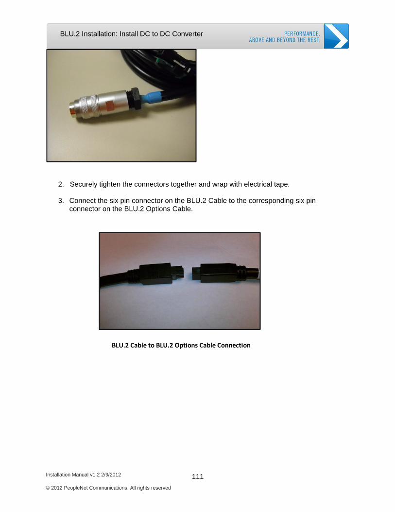
Installation Manual v1.2 2/9/2012 111 © 2012 PeopleNet Communications. All rights reserved
BLU.2 Installation: Install DC to DC Converter
2. Securely tighten the connectors together and wrap with electrical tape. 3. Connect the six pin connector on the BLU.2 Cable to the corresponding six pin
connector on the BLU.2 Options Cable.
BLU.2 Cable to BLU.2 Options Cable Connection
Installation Manual v1.2 2/9/2012 112 © 2012 PeopleNet Communications. All rights reserved
BLU.2 Installation: OBC Firmware Update
OBC Firmware Download
When the BLU.2 display powers up, you may or may not be directed to complete the OBC
Firmware Download. The OBC Firmware Download updates the OBC firmware with BLU.2
compatible code. The BLU.2 prompts you to complete the download, only if the OBC firmware
is different from the code version saved on BLU.2.
1. Insert the provided fuses to power up BLU.2 and the g3.
If the onboard computer (OBC) has the correct code, BLU.2 moves directly to Process Installation for activation (Skip to Complete BLU.2 Activation on the next page).
If the OBC needs a firmware update, then the PeopleNet Download Utility automatically launches and prompts, “Do you want to download software…?”.
2. Press Next to continue.
3. BLU.2 displays the same question.
4. Press Next again to continue.
The download begins and lasts about 7-10 minutes. The screen displays “Download complete” as each software packet is successfully
downloaded.
5. The download is completed when the screen displays “ALL FILES DOWNLOADED SUCCESSFULLY.”
6. Press Exit.
Installation Manual v1.2 2/9/2012 113 © 2012 PeopleNet Communications. All rights reserved
BLU.2 Installation: Complete BLU.2 Activation
Complete BLU.2 Activation
The BLU.2 activation process synchronizes the BLU.2 to the OBC and activates both the OBC
and BLU.2 on the PeopleNet System.
1. BLU.2 displays “W ould you like to process an installation?”. Select Yes.
2. BLU.2 displays “Is this a new installation?”. Select Yes.
If the OBC is already active on the PeopleNet System, then select No.
3. The BLU displays the next installation screen requesting your Installer ID, Truck
Number, and DSN Number (device serial number).
a. Enter your Installer ID in the text box labeled Installer ID. Press Tab.
b. Enter the Truck Number in the text box labeled Truck Number. Press Tab.
c. BLU displays the OBC DSN below the Submit button. Make sure the OBC DSN matches the DSN in the vehicle.
4. Press Submit.
If the 2nd green LED stops flashing and the screen has not changed, then press
Data Call to continue the installation. The screen changes and displays a message confirming successful installation.
The BLU.2 activation is complete, once you receive the installation confirmation message.
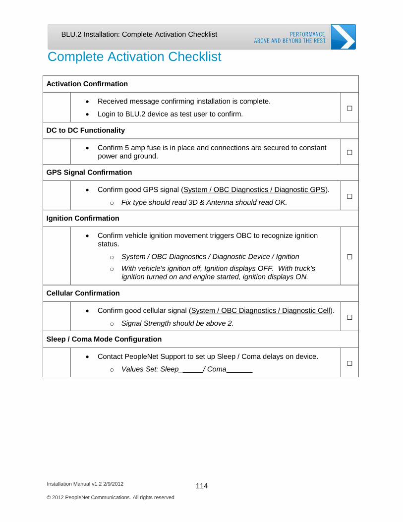
Installation Manual v1.2 2/9/2012 114 © 2012 PeopleNet Communications. All rights reserved
BLU.2 Installation: Complete Activation Checklist
Complete Activation Checklist
Activation Confirmation
• Received message confirming installation is complete.
• Login to BLU.2 device as test user to confirm.
□
DC to DC Functionality
• Confirm 5 amp fuse is in place and connections are secured to constant power and ground.
□
GPS Signal Confirmation
• Confirm good GPS signal (System / OBC Diagnostics / Diagnostic GPS).
o Fix type should read 3D & Antenna should read OK.
□
Ignition Confirmation
• Confirm vehicle ignition movement triggers OBC to recognize ignition status.
o System / OBC Diagnostics / Diagnostic Device / Ignition o With vehicle's ignition off, Ignition displays OFF. With truck's
ignition turned on and engine started, ignition displays ON.
□
Cellular Confirmation
• Confirm good cellular signal (System / OBC Diagnostics / Diagnostic Cell).
o Signal Strength should be above 2.
□
Sleep / Coma Mode Configuration
• Contact PeopleNet Support to set up Sleep / Coma delays on device.
o Values Set: Sleep_ / Coma
□

Vehicle Management Installation
Required System Components
Install J1708 Vehicle Management Cable
Install Multi-bus Adapater Vehicle Management Kit
Install OBD-II Vehicle Management Kit
Complete Installation Checklist
Installation Manual v1.2 2/9/2012
© 2012 PeopleNet Communications. All rights reserved
115

PerformX Installation: Required System Components
Installation Manual v1.2 2/9/2012 116 © 2012 PeopleNet Communications. All rights reserved
Vehicle Management Installation
Required System Components
The PeopleNet System collects data from the Engine Control/Computer Module (ECM) through
the Vehicle Management Cable or Kit. Collecting and reporting engine data are key functions of
the OBC. Engine data is used by the OBC to power many value added services such as
eDriver Logs and Performance Reporting.
The type of Vehicle Management Cable or Kit used to gather the information from the ECM
depends upon the make, model, and year of the truck. PeopleNet is able to read ECM data
from J1708 and J1939 data buses as well as OBD-II data. Please use Table 25 to ensure you
have the correct Vehicle Management Cables and Kits for your vehicles.
Table 26: Vehicle Management Compatibility Guide
Truck Engine/Year Multibus with
Repeater KIT: M-
010-0172
Multibus without
Repeater KIT: M-
010-0174
Universal PerformX
Cable PART: L- 016-0104
2-pin PerformX
Cable PART: L- 016-0106
OBD II
KIT: M-
010- 0151
Peterbilt All 1997 -2006 Yes - Not Required
No Yes No No
All 2007-2009 No Yes - Not Required
No Yes No
All 2010 - Newer
No Yes No No No
Kenworth All 1997 -2006 Yes - Not Required
No Yes No No
All 2007-2009 No Yes - Not Required
No Yes No
All 2010 - Newer
No Yes No No No
Freightliner All 1997 -2009 Yes - Not Required
No Yes No No
All 2010 - Newer
Yes No Yes No No
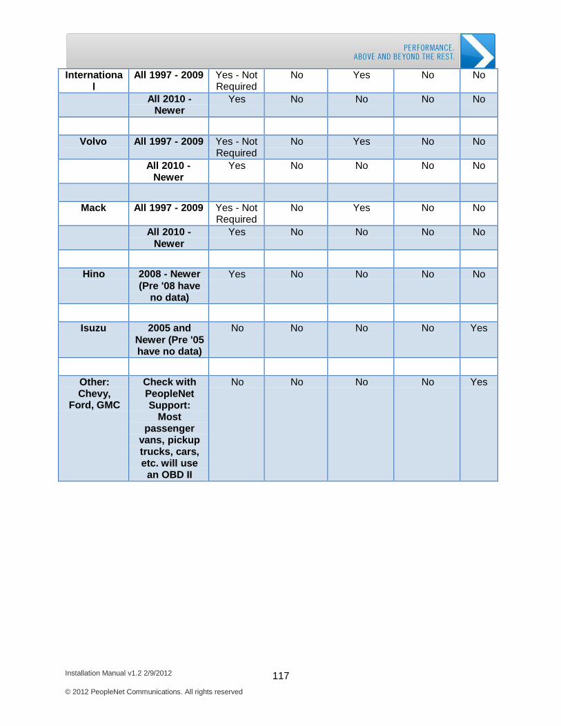
PerformX Installation: Required System Components
Installation Manual v1.2 2/9/2012 117 © 2012 PeopleNet Communications. All rights reserved
Internationa l
All 1997 - 2009 Yes - Not Required
No Yes No No
All 2010 - Newer
Yes No No No No
Volvo All 1997 - 2009 Yes - Not Required
No Yes No No
All 2010 - Newer
Yes No No No No
Mack All 1997 - 2009 Yes - Not Required
No Yes No No
All 2010 - Newer
Yes No No No No
Hino 2008 - Newer (Pre '08 have
no data)
Yes No No No No
Isuzu 2005 and Newer (Pre '05 have no data)
No No No No Yes
Other: Chevy,
Ford, GMC
Check with PeopleNet Support:
Most passenger
vans, pickup trucks, cars, etc. will use
an OBD II
No No No No Yes
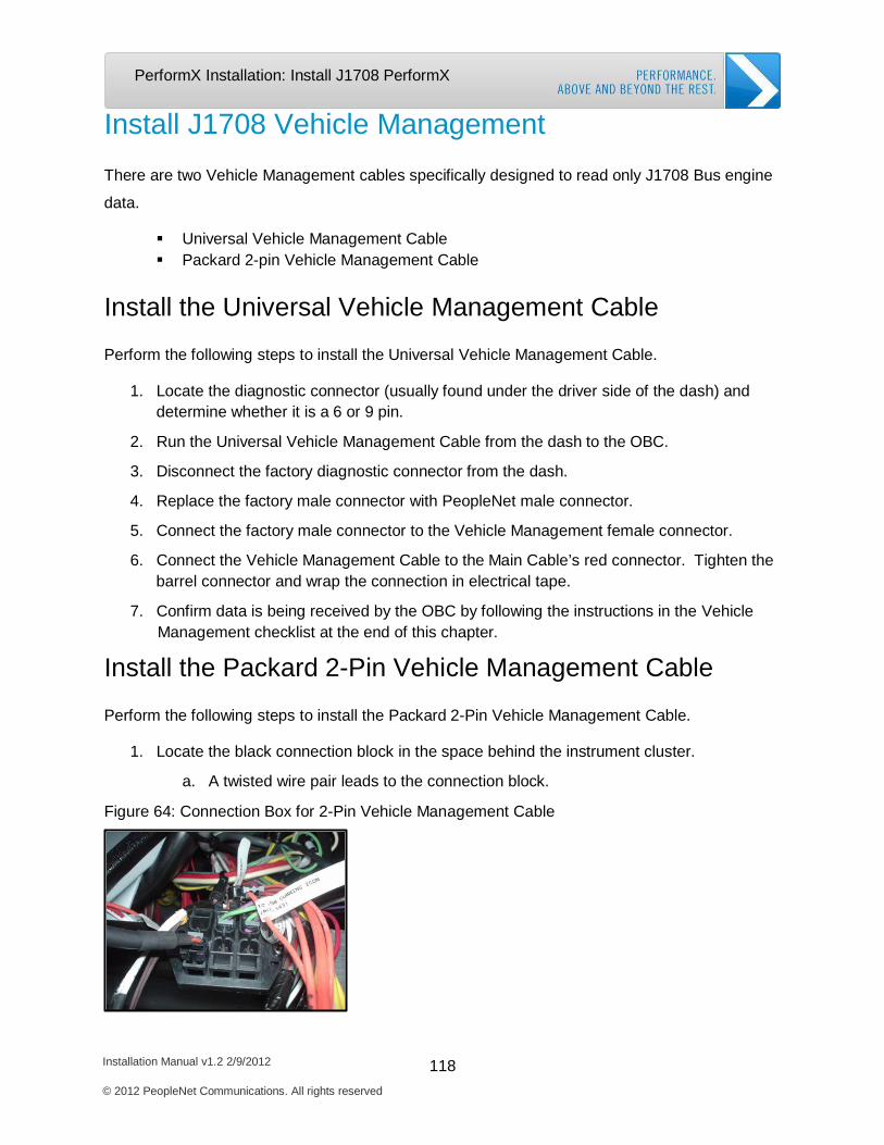
Installation Manual v1.2 2/9/2012 118 © 2012 PeopleNet Communications. All rights reserved
PerformX Installation: Install J1708 PerformX
Install J1708 Vehicle Management
There are two Vehicle Management cables specifically designed to read only J1708 Bus engine
data.
Universal Vehicle Management Cable Packard 2-pin Vehicle Management Cable
Install the Universal Vehicle Management Cable
Perform the following steps to install the Universal Vehicle Management Cable.
1. Locate the diagnostic connector (usually found under the driver side of the dash) and determine whether it is a 6 or 9 pin.
2. Run the Universal Vehicle Management Cable from the dash to the OBC.
3. Disconnect the factory diagnostic connector from the dash.
4. Replace the factory male connector with PeopleNet male connector.
5. Connect the factory male connector to the Vehicle Management female connector.
6. Connect the Vehicle Management Cable to the Main Cable’s red connector. Tighten the barrel connector and wrap the connection in electrical tape.
7. Confirm data is being received by the OBC by following the instructions in the Vehicle Management checklist at the end of this chapter.
Install the Packard 2-Pin Vehicle Management Cable
Perform the following steps to install the Packard 2-Pin Vehicle Management Cable.
1. Locate the black connection block in the space behind the instrument cluster.
a. A twisted wire pair leads to the connection block.
Figure 64: Connection Box for 2-Pin Vehicle Management Cable

Installation Manual v1.2 2/9/2012 119 © 2012 PeopleNet Communications. All rights reserved
PerformX Installation: Install J1708 PerformX
2. Insert the 2-Pin connector into any of the open connection points in the connection block.
3. Run the other end of the Vehicle Management Cable back to the OBC and connect the
red connector on the Vehicle Management Cable to the Red connector on the Main Cable. Tighten the barrel connector and wrap the connection with electrical tape.
4. Confirm data is being received by the OBC by following the instructions in the Vehicle Management checklist at the end of this chapter.
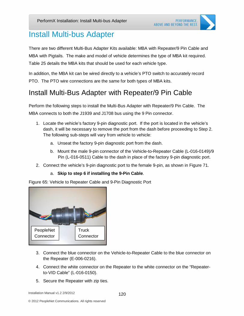
Installation Manual v1.2 2/9/2012 120 © 2012 PeopleNet Communications. All rights reserved
PerformX Installation: Install Multi-bus Adapter
Install Multi-bus Adapter
There are two different Multi-Bus Adapter Kits available: MBA with Repeater/9 Pin Cable and
MBA with Pigtails. The make and model of vehicle determines the type of MBA kit required.
Table 25 details the MBA kits that should be used for each vehicle type.
In addition, the MBA kit can be wired directly to a vehicle’s PTO switch to accurately record
PTO. The PTO wire connections are the same for both types of MBA kits.
Install Multi-Bus Adapter with Repeater/9 Pin Cable
Perform the following steps to install the Multi-Bus Adapter with Repeater/9 Pin Cable. The
MBA connects to both the J1939 and J1708 bus using the 9 Pin connector.
1. Locate the vehicle’s factory 9-pin diagnostic port. If the port is located in the vehicle’s dash, it will be necessary to remove the port from the dash before proceeding to Step 2. The following sub-steps will vary from vehicle to vehicle:
a. Unseat the factory 9-pin diagnostic port from the dash.
b. Mount the male 9-pin connector of the Vehicle-to-Repeater Cable (L-016-0149)/9 Pin (L-016-0511) Cable to the dash in place of the factory 9-pin diagnostic port.
2. Connect the vehicle’s 9-pin diagnostic port to the female 9-pin, as shown in Figure 71.
a. Skip to step 6 if installing the 9-Pin Cable.
Figure 65: Vehicle to Repeater Cable and 9-Pin Diagnostic Port
PeopleNet Connector
Truck Connector
3. Connect the blue connector on the Vehicle-to-Repeater Cable to the blue connector on the Repeater (E-006-0216).
4. Connect the white connector on the Repeater to the white connector on the “Repeater- to-VID Cable” (L-016-0150).
5. Secure the Repeater with zip ties.
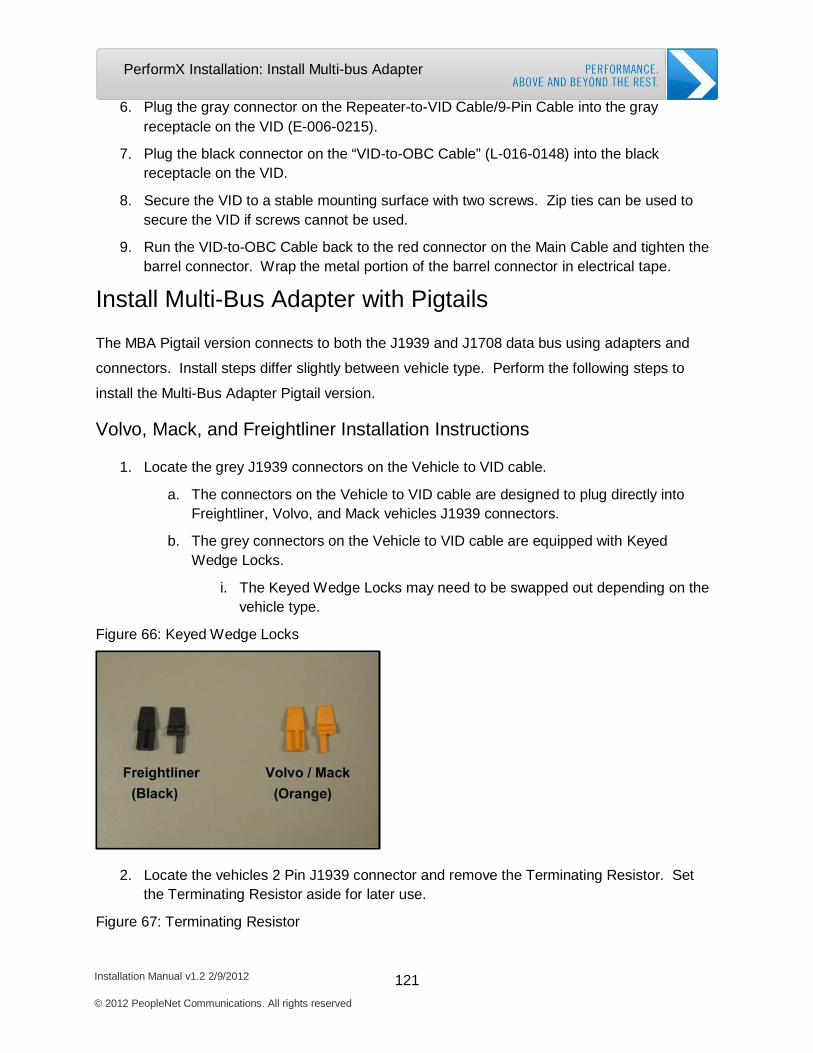
Installation Manual v1.2 2/9/2012 121 © 2012 PeopleNet Communications. All rights reserved
PerformX Installation: Install Multi-bus Adapter
6. Plug the gray connector on the Repeater-to-VID Cable/9-Pin Cable into the gray receptacle on the VID (E-006-0215).
7. Plug the black connector on the “VID-to-OBC Cable” (L-016-0148) into the black
receptacle on the VID.
8. Secure the VID to a stable mounting surface with two screws. Zip ties can be used to secure the VID if screws cannot be used.
9. Run the VID-to-OBC Cable back to the red connector on the Main Cable and tighten the barrel connector. Wrap the metal portion of the barrel connector in electrical tape.
Install Multi-Bus Adapter with Pigtails
The MBA Pigtail version connects to both the J1939 and J1708 data bus using adapters and
connectors. Install steps differ slightly between vehicle type. Perform the following steps to
install the Multi-Bus Adapter Pigtail version.
Volvo, Mack, and Freightliner Installation Instructions
1. Locate the grey J1939 connectors on the Vehicle to VID cable.
a. The connectors on the Vehicle to VID cable are designed to plug directly into Freightliner, Volvo, and Mack vehicles J1939 connectors.
b. The grey connectors on the Vehicle to VID cable are equipped with Keyed
Wedge Locks.
i. The Keyed Wedge Locks may need to be swapped out depending on the vehicle type.
Figure 66: Keyed Wedge Locks
2. Locate the vehicles 2 Pin J1939 connector and remove the Terminating Resistor. Set the Terminating Resistor aside for later use.
Figure 67: Terminating Resistor
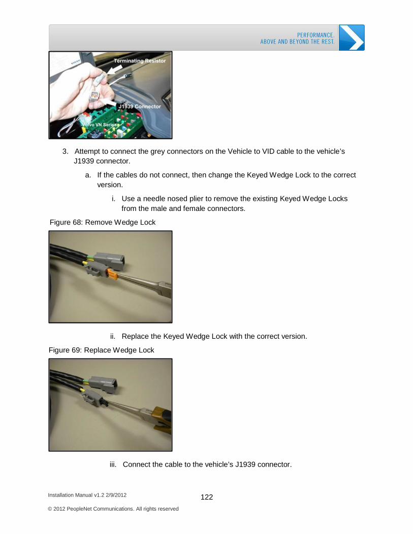
Installation Manual v1.2 2/9/2012 122 © 2012 PeopleNet Communications. All rights reserved
PerformX Installation: Install Multi-bus Adapter
3. Attempt to connect the grey connectors on the Vehicle to VID cable to the vehicle’s J1939 connector.
a. If the cables do not connect, then change the Keyed Wedge Lock to the correct
version.
i. Use a needle nosed plier to remove the existing Keyed Wedge Locks from the male and female connectors.
Figure 68: Remove Wedge Lock
ii. Replace the Keyed Wedge Lock with the correct version.
Figure 69: Replace Wedge Lock
iii. Connect the cable to the vehicle’s J1939 connector.

Installation Manual v1.2 2/9/2012 123 © 2012 PeopleNet Communications. All rights reserved
PerformX Installation: Install Multi-bus Adapter
4. Place the Terminating Resistor into the remaining J1939 connector on the Vehicle to VID cable.
a. The J1939 system requires the Terminating Resistor to prevent stray signals
from contaminating the data on the J1939 bus.
5. Locate the vehicle’s J1708 connector and plug in the Vehicle to VID cable.
a. You may need to use one of the adapters shipped with the kit to connect the cable.
b. Since not all vehicles have both J1708 and J1939 data buses, use Table 26 to determine whether or not the vehicle has a J1708 bus.
Table 27: J1708 and J1939 Data Bus List 2010 and Newer Trucks J1708 J1939
Freightliner* Yes YES Hino NO YES
International (Navistar)* NO YES Kenworth (Paccar) NO YES
Mack With Mack Engine YES YES Mack With Cummins Engine NO YES
Peterbilt (Paccar) NO YES Volvo With Volvo Engine YES YES
Volvo With Cummins Engine NO YES
*These trucks may be equipped with J1939/J1708 gateway that convert J1939 data into J1708
data.
6. Plug the grey connector on the Vehicle to VID cable into the grey receptacle on the VID.
7. Plug the black connector on the VID to OBC Cable into the black receptacle on the on the VID.
8. Secure the VID to a stable mounting surface with two screws. Zip ties can be used to secure the VID if screws cannot be used.
9. Run the VID to OBC cable to the OBC and connect the red barrel connector to the red barrel connector on the Main Cable. Wrap the connection completely in electrical tape.
Peterbilt and Kenworth Installation Instructions
1. Locate the appropriate adapter for the vehicle in the Backbone Connector Kit and plug it into the gray J1939 connector on the Vehicle to VID Cable.
2. Locate the vehicle’s J1939 connector and remove the Terminating Resistor. Set the resistor aside for later use.
Figure 70: Kenworth/Peterbilt J1939 Connector
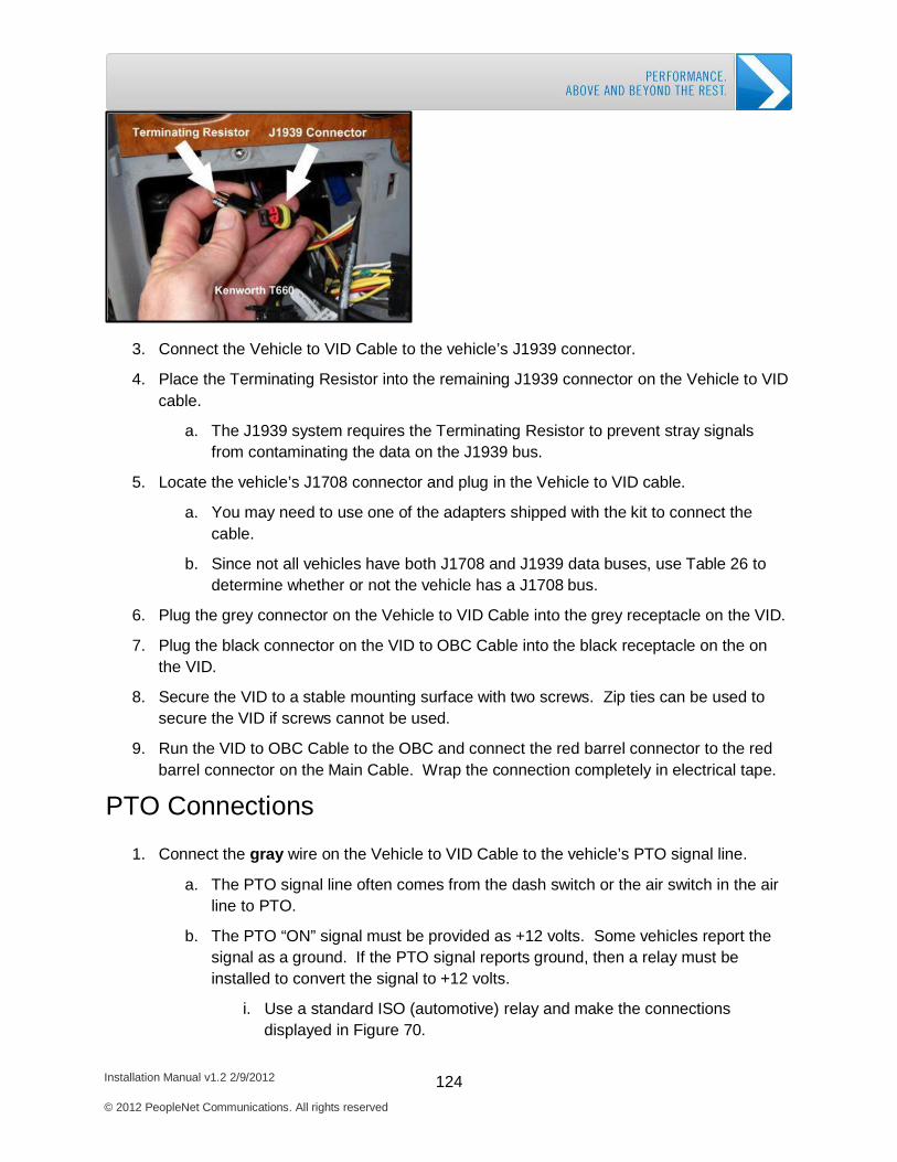
Installation Manual v1.2 2/9/2012 124 © 2012 PeopleNet Communications. All rights reserved
PerformX Installation: Install Multi-bus Adapter
3. Connect the Vehicle to VID Cable to the vehicle’s J1939 connector.
4. Place the Terminating Resistor into the remaining J1939 connector on the Vehicle to VID cable.
a. The J1939 system requires the Terminating Resistor to prevent stray signals
from contaminating the data on the J1939 bus.
5. Locate the vehicle’s J1708 connector and plug in the Vehicle to VID cable.
a. You may need to use one of the adapters shipped with the kit to connect the cable.
b. Since not all vehicles have both J1708 and J1939 data buses, use Table 26 to determine whether or not the vehicle has a J1708 bus.
6. Plug the grey connector on the Vehicle to VID Cable into the grey receptacle on the VID.
7. Plug the black connector on the VID to OBC Cable into the black receptacle on the on the VID.
8. Secure the VID to a stable mounting surface with two screws. Zip ties can be used to secure the VID if screws cannot be used.
9. Run the VID to OBC Cable to the OBC and connect the red barrel connector to the red barrel connector on the Main Cable. Wrap the connection completely in electrical tape.
PTO Connections
1. Connect the gray wire on the Vehicle to VID Cable to the vehicle’s PTO signal line.
a. The PTO signal line often comes from the dash switch or the air switch in the air line to PTO.
b. The PTO “ON” signal must be provided as +12 volts. Some vehicles report the signal as a ground. If the PTO signal reports ground, then a relay must be installed to convert the signal to +12 volts.
i. Use a standard ISO (automotive) relay and make the connections displayed in Figure 70.
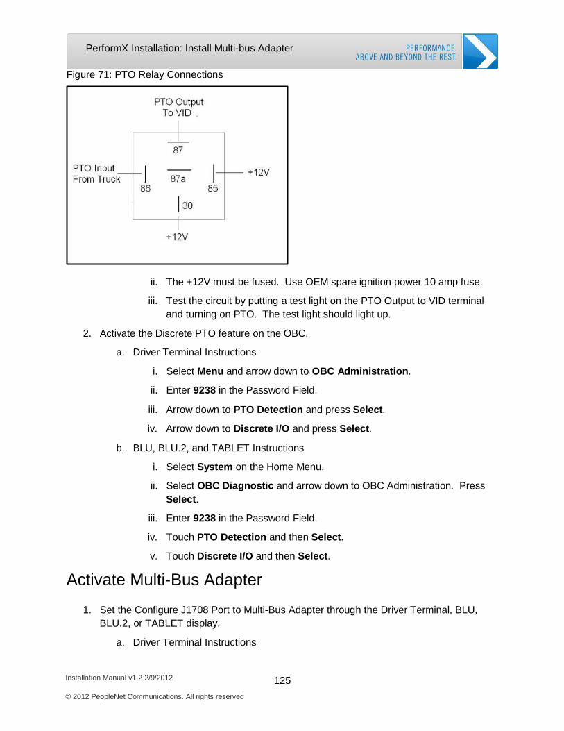
Installation Manual v1.2 2/9/2012 125 © 2012 PeopleNet Communications. All rights reserved
PerformX Installation: Install Multi-bus Adapter
Figure 71: PTO Relay Connections
ii. The +12V must be fused. Use OEM spare ignition power 10 amp fuse.
iii. Test the circuit by putting a test light on the PTO Output to VID terminal and turning on PTO. The test light should light up.
2. Activate the Discrete PTO feature on the OBC.
a. Driver Terminal Instructions
i. Select Menu and arrow down to OBC Administration.
ii. Enter 9238 in the Password Field.
iii. Arrow down to PTO Detection and press Select.
iv. Arrow down to Discrete I/O and press Select.
b. BLU, BLU.2, and TABLET Instructions
i. Select System on the Home Menu.
ii. Select OBC Diagnostic and arrow down to OBC Administration. Press Select.
iii. Enter 9238 in the Password Field.
iv. Touch PTO Detection and then Select.
v. Touch Discrete I/O and then Select.
Activate Multi-Bus Adapter
1. Set the Configure J1708 Port to Multi-Bus Adapter through the Driver Terminal, BLU, BLU.2, or TABLET display.
a. Driver Terminal Instructions
Installation Manual v1.2 2/9/2012 126 © 2012 PeopleNet Communications. All rights reserved
PerformX Installation: Install Multi-bus Adapter
i. Select Menu and arrow down to OBC Administration. Press Select.
ii. Enter 9238 in the Password Field.
iii. Select Assign J1708 Port.
iv. Select Multi-Bus Adapter.
b. BLU, BLU.2, and TABLET Instructions
i. Select System on the Home Menu.
ii. Select OBC Diagnostic and arrow down to OBC Administration. Press Select.
iii. Enter 9238 in the Password Field.
iv. Select J1709 Port Configuration.
v. Select Multi-Bus Adapter.
Functional Test
1. Start the vehicle’s engine, if you have not already done so, and allow it to idle for at least 30 seconds. The MBA does not start listening to the vehicle data until 30 seconds after the key is turned on.
2. Keep the engine running and verify data is being received on your LCD/BLU display:
a. Driver Terminal Instructions
i. Select MENU and arrow down to DIAGNOSTIC INFO. Press Select.
ii. If the “J” on the bottom row is followed by a “+” symbol, then engine data is being received.
iii. If the “J” is followed by a “-“ symbol, then there is no engine data being received.
b. BLU, BLU.2, and TABLET
i. Select System on the Home Menu.
ii. Select OBC Diagnostic, then Diagnostic Vehicle Management.
iii. PerfromX should display Yes.
3. If you are not getting engine data, then follow the MBA Troubleshooting instructions in Troubleshooting Guide on the PeopleNet Support Center.
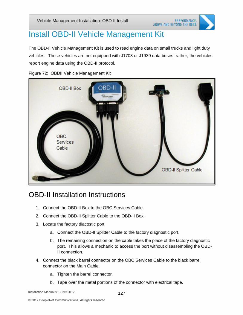
Installation Manual v1.2 2/9/2012 127 © 2012 PeopleNet Communications. All rights reserved
Vehicle Management Installation: OBD-II Install
Install OBD-II Vehicle Management Kit
The OBD-II Vehicle Management Kit is used to read engine data on small trucks and light duty
vehicles. These vehicles are not equipped with J1708 or J1939 data buses; rather, the vehicles
report engine data using the OBD-II protocol.
Figure 72: OBDII Vehicle Management Kit
OBD-II Installation Instructions
1. Connect the OBD-II Box to the OBC Services Cable.
2. Connect the OBD-II Splitter Cable to the OBD-II Box.
3. Locate the factory diacostic port.
a. Connect the OBD-II Splitter Cable to the factory diagnostic port.
b. The remaining connection on the cable takes the place of the factory diagnostic port. This allows a mechanic to access the port without disassembling the OBD- II connection.
4. Connect the black barrel connector on the OBC Services Cable to the black barrel connector on the Main Cable.
a. Tighten the barrel connector.
b. Tape over the metal portions of the connector with electrical tape.
Installation Manual v1.2 2/9/2012 128 © 2012 PeopleNet Communications. All rights reserved
Vehicle Management Installation: OBD-II Install
5. Securely mount the OBD-II Box in a safe location.
6. Mount the OBD-II Splitter Cable diagnostic port connection in an area convenient to maintenance.
Activate OBD-II
1. Assign the Serial Port to OBDII through the Driver Terminal, BLU, BLU.2, or TABLET display.
a. Driver Terminal
i. Select Menu.
ii. Scroll down to OBC Administration and press Select.
iii. Enter the password 9238 and press Select.
iv. Scroll down to Assign Serial Port and press Select.
v. Scroll down to OBDII and press Select.
vi. Press OK.
vii. The OBC reboots to complete the configuration
b. BLU, BLU.2, and TABLET
i. Select System on the Home Menu.
ii. Press OBC Diagnostic.
iii. Scroll down to OBC Administration and press Select.
iv. Enter password 9238 in the password field and select Enter.
v. Scroll down to Assign Serial Port and press Select.
vi. Scroll down to OBDII and press Select.
Functional Test
1. Turn the ignition to the ON position.
2. Allow up to three minutes for the OBD-II Box to boot up. Check the LED light on the OBD-II Box.
a. Solid red indicates full power mode.
b. Slowly blinking or rapidly blinking red light indicates low power mode. Check the
OBD-II troubleshooting guide to resolve.
3. Check the PerformX Diagnostic information to make sure the OBD-II is reporting data.
a. Driver Terminal
i. Select Menu.

Installation Manual v1.2 2/9/2012 129 © 2012 PeopleNet Communications. All rights reserved
Vehicle Management Installation: OBD-II Install
ii. Scroll down to Diagnostic Info and press Select.
iii. If the “J” on the bottom row is followed by a “+” symbol, engine data is being received.
iv. If the “J” is followed by a “-“ symbol, there is no engine data being received.
b. BLU, BLU.2, and TABLET
i. Select System on the Home Menu.
ii. Select OBC Diagnostic, then Diagnostic PerformX.
iii. PerfromX should display Yes.

Installation Manual v1.2 2/9/2012 130 © 2012 PeopleNet Communications. All rights reserved
Vehicle Management Installation: OBD-II Install
Complete Vehicle Management Checklist
Driver Terminal Checklist
2 Pin Packard Cable/Universal Vehicle Management Cable
□
• Device shows Vehicle Management active on device (Menu / Diagnostic Info / J+ present).
o J should show (+).
□
Multibus Vehicle Management Cable
□
• Enable Multi-Bus Adaptor.
o Menu / OBC Administration / Enter Password (9238) / J1708 Port Configuration / Multi- Bus Adaptor
□
• Device shows Vehicle Management active on display (Menu / Diagnostic Info / J+).
o J should be (+), if (-) contact PeopleNet Customer Support .
□
• Set Discrete PTO, if required (Menu / OBC Administration / Enter Password (9238) / PTO Detection / Discrete I/O).
□
Odometer Offset
• If odometers do not match, offset the odometer to match the vehicle’s dash.
o Menu / OBC Administration/ Enter Password (9238) / Odometer Sync / ECM ODO Offset / Create ODO Offset / Enter Dash Odometer
o If offset is completed, please note initial and offset value.
Initial Odometer: Offset Odometer:
□
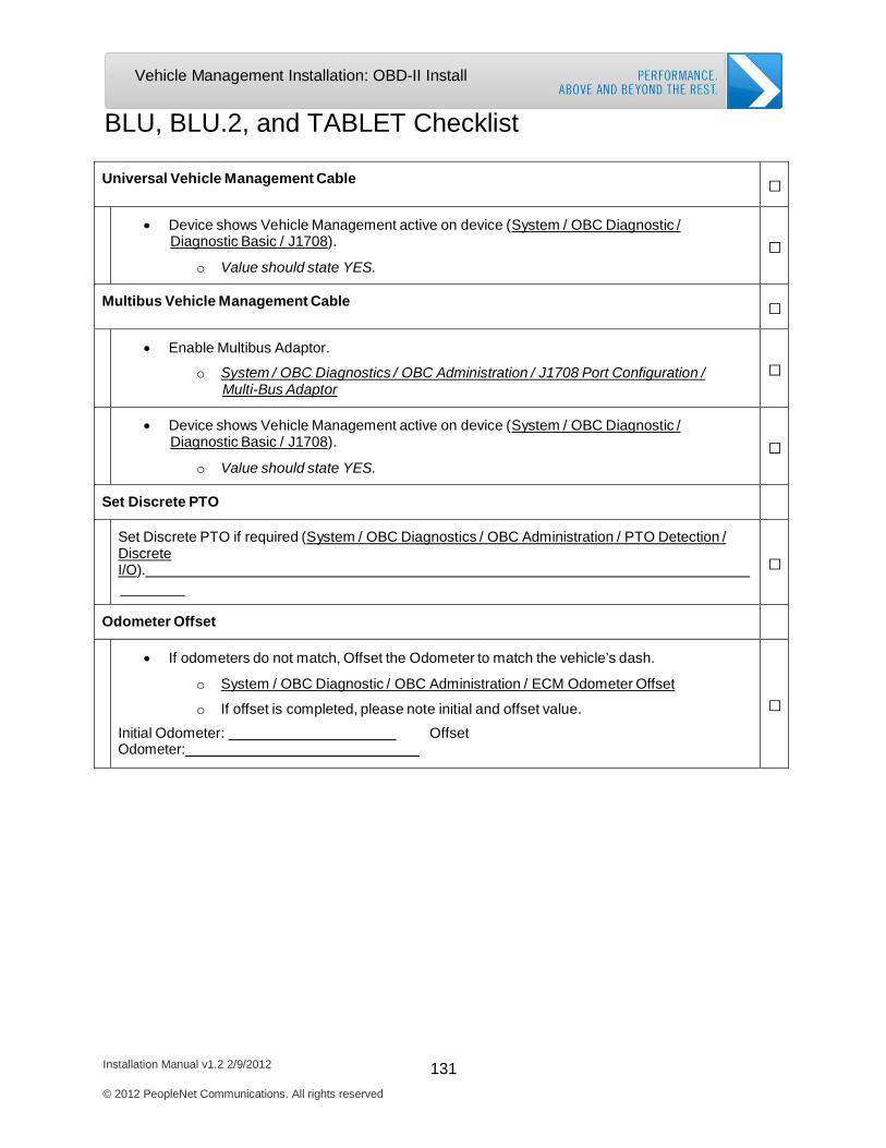
Installation Manual v1.2 2/9/2012 131 © 2012 PeopleNet Communications. All rights reserved
Vehicle Management Installation: OBD-II Install
BLU, BLU.2, and TABLET Checklist
Universal Vehicle Management Cable
□
• Device shows Vehicle Management active on device (System / OBC Diagnostic / Diagnostic Basic / J1708).
o Value should state YES.
□
Multibus Vehicle Management Cable
□
• Enable Multibus Adaptor.
o System / OBC Diagnostics / OBC Administration / J1708 Port Configuration / Multi-Bus Adaptor
□
• Device shows Vehicle Management active on device (System / OBC Diagnostic / Diagnostic Basic / J1708).
o Value should state YES.
□
Set Discrete PTO
Set Discrete PTO if required (System / OBC Diagnostics / OBC Administration / PTO Detection / Discrete I/O).
□
Odometer Offset
• If odometers do not match, Offset the Odometer to match the vehicle’s dash.
o System / OBC Diagnostic / OBC Administration / ECM Odometer Offset
o If offset is completed, please note initial and offset value. Initial Odometer: Offset Odometer:
□

Satellite Modem Installation
Required System Components
Mount the Satellite Antenna
Mount the Satellite Modem
Activate the Satellite Modem
Installation Manual v1.2 2/9/2012
© 2012 PeopleNet Communications. All rights reserved
132

Satellite Modem Install: System Components
Installation Manual v1.2 2/9/2012 133 © 2012 PeopleNet Communications. All rights reserved
Satellite Modem Installation
Required System Components
The Satellite Modem allows the PeopleNet System to communicate in areas without cell
coverage using low earth orbit satellites. Two kits are required to install the Satellite Modem.
The Satellite Modem Kit includes the Satellite Modem. The Satellite Modem Installation Kit
includes the OBC Services Cable, Satellite Antenna, and Screw Packets. Prior to starting your
installation, compare the parts you received with the satellite kits listed in Chapter 1.
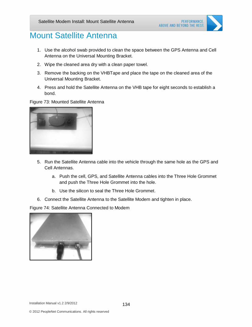
Installation Manual v1.2 2/9/2012 134 © 2012 PeopleNet Communications. All rights reserved
Satellite Modem Install: Mount Satellite Antenna
Mount Satellite Antenna
1. Use the alcohol swab provided to clean the space between the GPS Antenna and Cell Antenna on the Universal Mounting Bracket.
2. Wipe the cleaned area dry with a clean paper towel.
3. Remove the backing on the VHBTape and place the tape on the cleaned area of the
Universal Mounting Bracket.
4. Press and hold the Satellite Antenna on the VHB tape for eight seconds to establish a bond.
Figure 73: Mounted Satellite Antenna
5. Run the Satellite Antenna cable into the vehicle through the same hole as the GPS and Cell Antennas.
a. Push the cell, GPS, and Satellite Antenna cables into the Three Hole Grommet
and push the Three Hole Grommet into the hole.
b. Use the silicon to seal the Three Hole Grommet.
6. Connect the Satellite Antenna to the Satellite Modem and tighten in place.
Figure 74: Satellite Antenna Connected to Modem
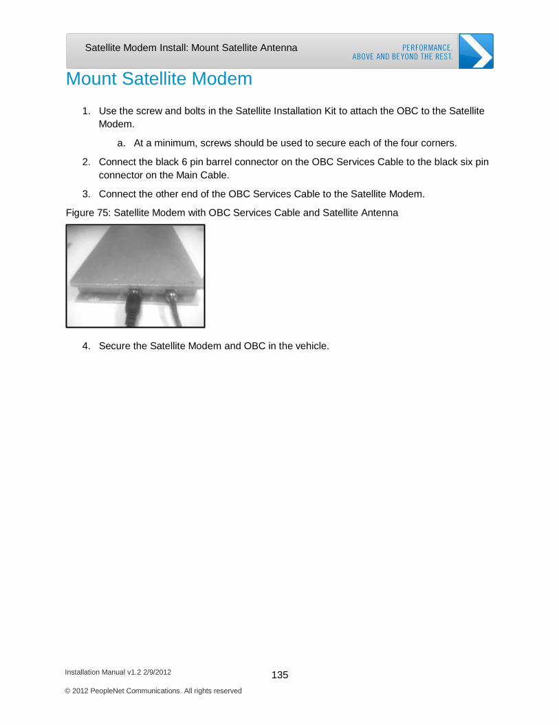
Installation Manual v1.2 2/9/2012 135 © 2012 PeopleNet Communications. All rights reserved
Satellite Modem Install: Mount Satellite Antenna
Mount Satellite Modem
1. Use the screw and bolts in the Satellite Installation Kit to attach the OBC to the Satellite Modem.
a. At a minimum, screws should be used to secure each of the four corners.
2. Connect the black 6 pin barrel connector on the OBC Services Cable to the black six pin
connector on the Main Cable.
3. Connect the other end of the OBC Services Cable to the Satellite Modem.
Figure 75: Satellite Modem with OBC Services Cable and Satellite Antenna
4. Secure the Satellite Modem and OBC in the vehicle.
Installation Manual v1.2 2/9/2012 136 © 2012 PeopleNet Communications. All rights reserved
Satellite Modem Install: Activate Satellite Modem
Activate the Satellite Modem
Activate Satellite for Driver Terminal
1. Select Menu.
2. Arrow down to OBC Administration and press Select.
3. Enter 9238 in the Password Field.
4. Arrow down to Assign Serial Port and press Select.
5. Arrow down to Satellite Modem and press Select.
6. OBC notifies this action will cause reboot. Press OK.
7. Send a test message from the OBC to register the Satellite Modem with the PeopleNet System.
8. Access the OBC Administration screen again (steps 1-3).
9. Arrow down to Sat Channel Test and press Select.
a. If Sat Channel Test is successful, then proceed to the next step.
b. If Sat Channel Test is unsuccessful, then contact PeopleNet Support for
additional help.
10. Access the OBC Administration menu.
11. Arrow down to Satellite Call and press Select.
12. Install complete when Satellite call completes.
Activate Satellite for BLU, BLU.2, and TABLET
1. Select System on the Home Menu.
2. Select OBC Diagnostic and arrow down to OBC Administration. Press Select.
3. Enter 9238 in the Password Field.
4. Select Assign Serial Port and then select Satellite Modem.
5. OBC notifies this action will cause reboot. Press OK.
6. Send a test message from the OBC to register the Satellite Modem with the PeopleNet System.
7. Access OBC Administration menu again (steps 1-4).
8. Select Sat Channel Test.
a. If Sat Channel Test is successful, then proceed to next step
b. If Sat Channel Test is unsuccessful, then contact PeopleNet Support.

Installation Manual v1.2 2/9/2012 137 © 2012 PeopleNet Communications. All rights reserved
Satellite Modem Install: Activate Satellite Modem
9. Access the OBC Administration menu (Repeat steps 1-4).
10. Arrow down to Satellite Call and press Select.
11. Install complete when Satellite call completes.