Embed Size (px)
Citation preview

People Helping People Build a Safer World®
Lee Clifton, Senior Director of PMG Resources, Government Relations
Methods of Venting Plumbing Fixtures and Traps in the 2021 IPCInstallation, Flexibility and Opportunity for Savings

Chapter 9 of the International Plumbing Code® (IPC®) describes a variety of methods to vent plumbing fixtures and traps. The methods have been laboratory tested to determine sizing and installation requirements that provide proper venting to a drainage system. The venting methods have also been field tested, establishing a long history of satisfactory service.
In this publication, we will present the various approaches to venting that are permitted in the 2021 IPC. You will find that these venting provisions offer the installer and designer different paths to achieving an adequately vented system, which could result in cost savings along with ease of installation in different types of construction.
Three Specific Venting Methods
Section 901.2.1 of the IPC establishes that traps and trapped fixtures shall be vented in accordance with one of the venting methods specified in this Chapter. Section 904.1 requires the vent system serving each building drain to have at least one vent pipe that extends to the outdoors.
The most widely used method is commonly referred to as a conventional venting system. Table 909.1 (below) provides the maximum distance allowed for a vent in relation to the trap. A fixture vent connected in this manner is called an individual vent. These individual vents are sized according to Section 906.2. Here we find that the vent must be at least one-half the diameter of the drain served, but in no case less than 1¼ inches in diameter.
TABLE 909.1 Maximum Distance of Fixture Trap from Vent
Size of Trap (inches)
Slope (inch per foot)
Distance from Trap (feet)
1¼ ¼ 5
1½ ¼ 6
2 ¼ 8
3 1⁄8 12
4 1⁄8 16For SI: 1 inch = 25.4 mm.
Remember, the vent size is not based on the trap or fixture drain (trap arm), but the drain size that continues downstream from the point where the vent and fixture drain connect. The drain size is determined by the fixture unit load in accordance with Tables 709.1, 709.2, 710.1(1), and 710.1(2) in the IPC. Hence, if the drain size is 4 inches (102 mm), a 2-inch (51 mm) vent is required. A 3-inch (76 mm) drain would require a 1½-inch (38 mm) vent. A 2-inch (51 mm), 1½-inch or 1¼-inch (38 or 31.8 mm) drain would require a minimum 1¼-inch (31.8 mm) vent, this being the minimum size allowed.
Section 905.5 allows individual vents to merge with each other, as long as the connection is made at least 6 inches above the flood-level rim of the highest fixture served. Sizing of
Chapter 9 of the International Plumbing Code (IPC) describes a variety of methods to vent plumbing fixtures and traps.
2 Methods of Venting Plumbing Fixtures and Traps in the 2021 IPC
the vents as they connect is again based only on the required size of the drain being served. Section 906.2 requires that vents exceeding 40 feet (1016 mm) in developed length shall be increased by one nominal pipe size for the entire developed length of the vent pipe.
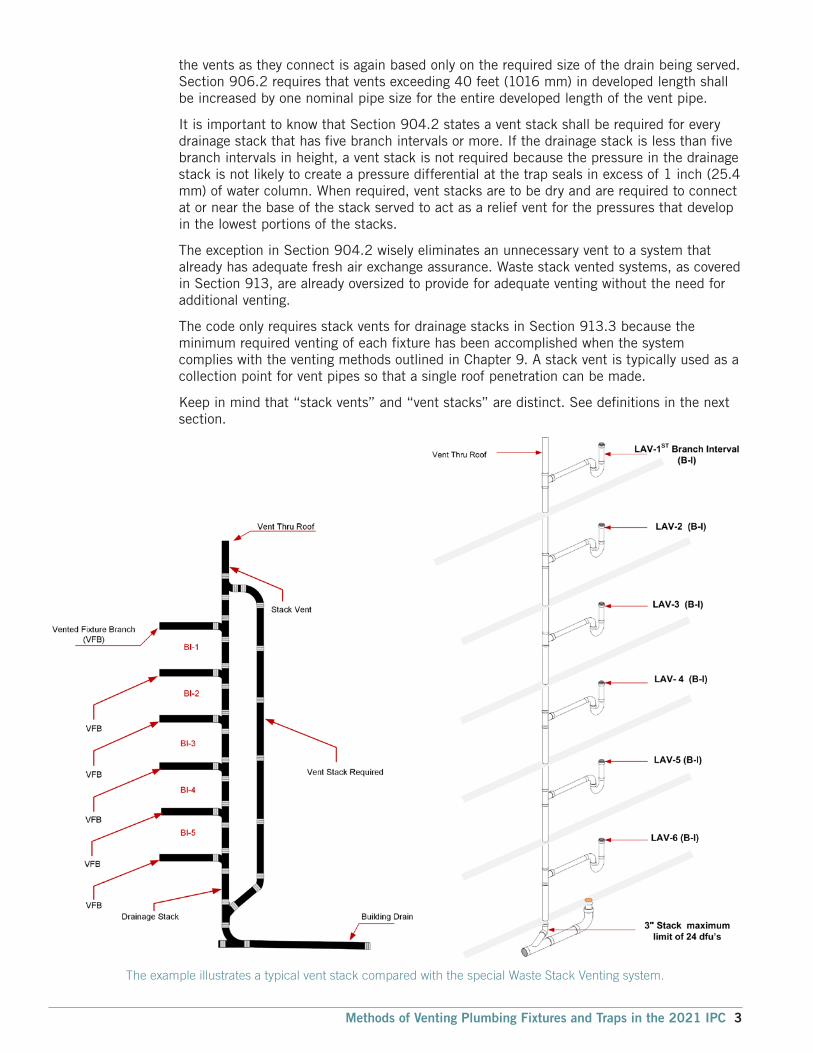
It is important to know that Section 904.2 states a vent stack shall be required for every drainage stack that has five branch intervals or more. If the drainage stack is less than five branch intervals in height, a vent stack is not required because the pressure in the drainage stack is not likely to create a pressure differential at the trap seals in excess of 1 inch (25.4 mm) of water column. When required, vent stacks are to be dry and are required to connect at or near the base of the stack served to act as a relief vent for the pressures that develop in the lowest portions of the stacks.
The exception in Section 904.2 wisely eliminates an unnecessary vent to a system that already has adequate fresh air exchange assurance. Waste stack vented systems, as covered in Section 913, are already oversized to provide for adequate venting without the need for additional venting.
The code only requires stack vents for drainage stacks in Section 913.3 because the minimum required venting of each fixture has been accomplished when the system complies with the venting methods outlined in Chapter 9. A stack vent is typically used as a collection point for vent pipes so that a single roof penetration can be made.
Keep in mind that “stack vents” and “vent stacks” are distinct. See definitions in the next section.
The example illustrates a typical vent stack compared with the special Waste Stack Venting system.
Methods of Venting Plumbing Fixtures and Traps in the 2021 IPC 3

Definitions
Branch Vent. A vent connecting one or more individual vents with a vent stack or stack vent.
Circuit Vent. A vent that connects to a horizontal drainage branch and vents two traps to no more than eight traps or trapped fixtures connected into a battery.
Combination Waste and Vent System. A specially designed system of waste piping embodying the horizontal wet venting of one or more sinks or floor drains by means of a common waste and vent pipe adequately sized to provide free movement of air above the flow line of the drain.
Common Vent. A vent connecting at the junction of two fixture drains or to a fixture branch and serving as a vent for both fixtures.
Individual Vent. A pipe installed to vent a fixture trap and that connects with the vent system above the fixture served or terminates in the open air.
Stack Vent. The extension of a soil or waste stack above the highest horizontal drain connected to the stack.
Stack Venting. A method of venting a fixture or fixtures through the soil or waste stack.
Vent Stack. A vertical vent pipe installed primarily for the purpose of providing circulation of air to and from any part of the drainage system.
The developed length of individual, branch, circuit, and relief vents shall be measured from the farthest point of vent connection to the drainage system to the point of connection to the vent stack, stack vent, or termination outside of the building.
There are important criteria to remember when sizing a conventional venting system composed of individual fixture vents, vent stacks, and stack vents. The minimum size of an individual vent is one-half the required drain size, whereas the minimum size of the vent stacks and stack vents is one-half the size of the drain served.
The sizing criteria for stack vents and vent stacks are based on three variables:
1. The developed length of the vent.
2. The size of the stack served by the vent.
3. The total drainage fixture unit (DFU) connected to the stack.
Example A:
A 3-inch (76 mm) soil stack with a stack vent serving as the required vent extension to the outdoors, connecting to a 3-inch (76 mm) building drain, must have at least a 1½-inch (38 mm) stack vent [maximum of 102 fixture units served and a maximum 25-foot (7620 mm) developed length] in accordance with Section 906.1 and Table 906.1. This 1½-inch (38 mm) stack vent is the minimum size required to comply with this section because it is at least one-half the size of the building drain.
4 Methods of Venting Plumbing Fixtures and Traps in the 2021 IPC

TABLE 906.1 Size and Developed Length of Stack Vents and Vent Stacks
DIAMETER OF SOIL OR WASTE
STACK (inches)
TOTAL FIXTURE UNITS BEING
VENTED (dfu)
MAXIMUM DEVELOPED LENGTH OF VENT (feet)a DIAMETER OF VENT (inches)
1¼ 1½ 2 2½ 3 4 5 6 8 10 12
1¼ 2 30
1½ 8 50 150 ﹘ ﹘ ﹘ ﹘ ﹘ ﹘ ﹘ ﹘ ﹘
1½ 10 30 100
2 12 30 75 200
2 20 26 50 150 ﹘ ﹘ ﹘ ﹘ ﹘ ﹘ ﹘
2½ 42 30 100 300
3 10 42 150 360 1,040
3 21 ﹘ 32 110 270 810 ﹘ ﹘ ﹘ ﹘ ﹘ ﹘
3 53 27 94 230 680
3 102 25 86 210 620
4 43 ﹘ 35 85 250 980 ﹘ ﹘ ﹘ ﹘ ﹘
4 140 27 65 200 750
4 320 23 55 170 640
4 540 21 50 150 580
5 190 28 82 320 990
5 490 21 63 250 760
5 940 18 53 210 670
5 1,400 16 49 190 590
6 500 33 130 400 1,000
6 1,100 26 100 310 780
6 2,000 22 84 260 660
6 2,900 20 77 240 600
8 1,800 31 95 240 940
8 3,400 24 73 190 729
For SI: 1 inch = 25.4 mm, 1 foot = 304.8 mm. aThe developed length shall be measured from the vent connection to the open air.
Non-Conventional Venting Methods
Proper application of these venting options can substantially reduce the amount of pipe and fittings used, while still providing proper venting. Inspectors and plumbers often overlook the opportunities afforded by these different venting methods, which have been proven to save money and may be helpful in areas where conventional venting methods may be difficult to install.
Quality venting systems take careful planning
Methods of Venting Plumbing Fixtures and Traps in the 2021 IPC 5

Island Fixture Venting
This is a specific method for venting an island sink, one limited to sinks and lavatories. Residential kitchen sinks with a dishwasher waste connection, a food waste grinder, or both, in combination with the kitchen sink waste, shall be permitted.
The island fixture vent shall connect to the fixture drain as required for an individual or common vent. The vent shall rise vertically to above the drainage outlet of the fixture being vented before offsetting horizontally or vertically downward. The vent or branch vent for multiple island fixture vents shall extend to a minimum of 6 inches (152 mm) above the highest island fixture being vented before connecting to the outside vent terminal.
The vent located below the flood level rim of the fixture being vented shall be installed as required for drainage piping in accordance with Chapter 7, except for sizing. The vent shall be sized in accordance with Section 906.2. The lowest point of the island fixture vent shall connect full size to the drainage system.
The connection shall be to a vertical drain pipe or to the top half of a horizontal drain pipe. Cleanouts shall be provided in the island fixture vent to permit rodding of all vent piping located below the flood level rim of the fixtures. Rodding in both directions shall be permitted through a cleanout.
As you can see from the diagram for this installation, this venting method provides for a free flow of air where liquid is not being trapped in the lowest portion of the vent, because of its connection to the drain. This method will work well in a crawl space or underground application.
Relief Vents—Stacks of More than 10 Branch Intervals
This venting method requires a relief vent equal to the size of the vent stack it connects with for buildings exceeding 10 branch intervals. A relief vent must be located at every 10 branch intervals, measured from the highest horizontal drainage branch, and then calculated downward to the base of the stack.
The lower end of the relief vent is connected to the soil or waste stack below the level of
Island Fixture Vent
The graphic illustrates a relief vent connection.
6 Methods of Venting Plumbing Fixtures and Traps in the 2021 IPC

the horizontal branch that serves the floor level within the branch interval required to have the relief vent. The location of this connection is intended to allow waste that might get into the relief vent, including condensation, to reach a waste line. This connection is made using a wye fitting installed as a drainage fitting in order to not impair the flow. The upper connection of the relief vent is made to the vent stack and is to be located a minimum of 3 feet (914 mm) above the floor level of the same horizontal branch. This connection is made using a wye fitting installed in an inverted position. The required 3-foot (914 mm) minimum height required is a common theme in Chapter 9 and is intended to prevent waste flow from entering the vent stack.
Air Admittance Valves
The air admittance valve (AAV) is a device designed to allow air to enter the drainage system to balance the pressure and prevent siphonage of the water trap when negative pressure develops in the system. In this way, it is used on individual vents, branch vents and circuit vents in lieu of terminating vents to the exterior of the structure. Stack vents and vent stacks are permitted to terminate to a stack type AAV. The exception is for stack vents or vent stacks that serve drainage stacks exceeding six branch intervals.
Because the AAV will not provide relief of positive pressures, there are certain installation requirements specified in the IPC to relieve positive pressure. The one open pipe vent required on every building drainage system in section 918.7 of the IPC, Vent Required, and section 904.1 of the IPC, Required Vent Extension, mandates that at least one vent pipe shall extend to the outdoors to relieve the system’s positive pressure. See Figure 1. Section 918.3.1, Horizontal Branches of the IPC, contains measures for pressure relief by requiring the
installation of a relief vent where the horizontal branch is located more than four branch intervals from the top of the stack.
An AAV without an engineered design shall not be utilized to vent sumps or tanks of any type. Figure 2 shows an example of one manufacturer’s engineered design for use of an AAV on a sump.
An AAV has one moving part, a seal, which must be maintained a safe distance above the drain served. In the event of a drain stoppage, the seal may become inoperable or operate improperly if waste is permitted to rise into the AAV assembly.
Figure 1: Air Admittance—Individual Vent
Figure 2: The graphic is an example of an engineered design
Methods of Venting Plumbing Fixtures and Traps in the 2021 IPC 7

The AAV need not extend above the flood level rim of the fixture served because in the event of a drain blockage, the device will trap air between it and the rising waste, thereby protecting the device from contamination. The illustration of the AAV in Figure 3 is shown in the closed position. The valve is designed to close and seal under zero or positive pressure.
AAV’s shall be installed in accordance with the requirements of section 918 and the manufactures instruction. The AAV’s shall be installed after the DWV testing required by Section 312.2 or 312.3 has been performed.
Individual and branch-type air admittance valves shall not be located not less than 4 inches (102 mm) above the horizontal branch drain or fixture drain being vented. (See Figure 4, Examples 1 and 2)
AAVs shall be accessible, should replacement be required. Such valves shall be installed in a location that allows air to enter the valve. Locating the valve in a sink or vanity cabinet is accessible. For in wall installation, use a recess box/grill combination or access grill. See Figure 5.
The AAV shall be installed not less than 6 inches (152 mm) above insulation material. See Figure 6.
The stack-type AAV shall be located not less than 6 inches (152 mm) above the flood level rim of the highest fixture being vented. The AAV shall be located within the maximum developed length permitted for the vent. See Figure 7.
AAVs shall be accessible, should replacement be required. Such valves shall be installed in a location that allows air to enter the valve. The AAV shall be installed not less than 6 inches (152 mm) above insulation materials that may block air inlets or otherwise impair the operation of the device.
In summarizing, the installation of AAVs must conform to the requirements of section 918 of the IPC, Air Admittance Valves, or section P3113 of the IRC, Vent Pipe Sizing, and the manufacturers instruction. Where differences occur between the provisions of the code and the manufacturer instructions, the most restrictive provisions must apply.
Figure 3: Air admittance valve closes and seals under zero or positive pressures
Figure 5: Wall Access
Figure 7 Stack Type Air Admittance Valve
Figure 6: Attic Access
Figure 4: Distance Above Drain
Example 1 Example 2
8 Methods of Venting Plumbing Fixtures and Traps in the 2021 IPC

Engineered Vent Systems
This type of venting system is considered to be an alternative engineered design. Notice that according to Table 919.2, which provides criteria for determining cubic feet or air flow per minute for various diameters of pipe, a vent can be as small as ½ inch in diameter.
After the individual vent airflow rate is determined by the equation in Section 919.2, the size and developed length are determined by Table 919.2. The values in the table indicate the maximum developed length for a given pipe size and the individual vent airflow rate. Note that the engineered vent system must be designed, signed and sealed by a registered design professional and will need to be submitted for review by the code official in accordance with Section 105 of the IPC.
Common Vent
This very simple concept allows two traps to be vented by the same vent. The two traps and their fixture drains can be either at the same level or at different levels, provided that they are on the same floor. The following diagrams show some of the various approaches to common venting. The sizing of common venting is specified in Table 911.3.
Common Vent with Fixture Drains Connecting at Same Level
TABLE 919.2 Minimum Diameter and Maximum Length of Individual Branch
Fixture Vents and Individual Fixture Header Vents for Smooth Pipes
DIAMETER OF VENT PIPE (inches)
INDIVIDUAL VENT AIRFLOW RATE (cubic feet per minute)Maximum developed length of vent (feet)
1 2 3 4 5 6 7 8 9 10 11 12 13 14 15 16 17 18 19 20½ 95 25 13 8 5 4 3 2 1 1 1 1 1 1 1 1 1 1 1 1
¾ 100 88 47 30 20 15 10 9 7 6 5 4 3 3 3 2 2 2 2 1
1 100 65 48 37 29 24 20 17 14 12 11 9 8 7 7 6 6
1¼ 100 73 62 53 40 32 29 26 23 21
1½ 100 96 75 65 60 54 49 45
2 100
For SI: 1 inch = 25.4 mm, 1 cubic foot per minute = 0.4719 L/s, 1 foot = 304.8 mm.
TABLE 911.3 Common Vent Size
Pipe Size (inches)
Maximum Discharge From Upper Fixture
Drain (dfu)1½ 1
2 4
2½ to 3 6For SI: 1 inch = 25.4 mm.
Methods of Venting Plumbing Fixtures and Traps in the 2021 IPC 9

(Left) Example 1: Individual Vent as Common Vent (Double Wye Used in the Vertical)
(Above) Example 2: Individual Vent as Common Vent
Example 3: Individual Vent based on size of Common Drainage Vent
10 Methods of Venting Plumbing Fixtures and Traps in the 2021 IPC
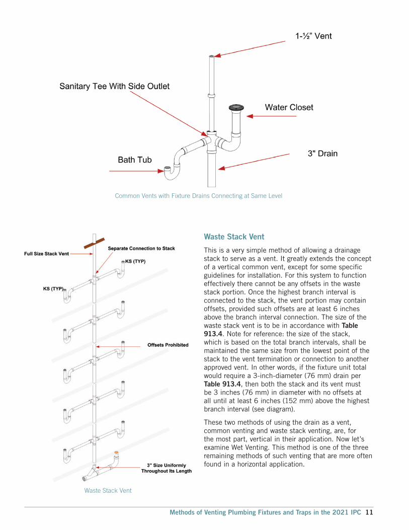
Waste Stack Vent
This is a very simple method of allowing a drainage stack to serve as a vent. It greatly extends the concept of a vertical common vent, except for some specific guidelines for installation. For this system to function effectively there cannot be any offsets in the waste stack portion. Once the highest branch interval is connected to the stack, the vent portion may contain offsets, provided such offsets are at least 6 inches above the branch interval connection. The size of the waste stack vent is to be in accordance with Table 913.4. Note for reference: the size of the stack, which is based on the total branch intervals, shall be maintained the same size from the lowest point of the stack to the vent termination or connection to another approved vent. In other words, if the fixture unit total would require a 3-inch-diameter (76 mm) drain per Table 913.4, then both the stack and its vent must be 3 inches (76 mm) in diameter with no offsets at all until at least 6 inches (152 mm) above the highest branch interval (see diagram).
These two methods of using the drain as a vent, common venting and waste stack venting, are, for the most part, vertical in their application. Now let’s examine Wet Venting. This method is one of the three remaining methods of such venting that are more often found in a horizontal application.
Common Vents with Fixture Drains Connecting at Same Level
Waste Stack Vent
Methods of Venting Plumbing Fixtures and Traps in the 2021 IPC 11

Wet Venting
A fixture is said to be wet vented when it serves also to carry the discharge from fixtures connecting into the drainage system at a higher level. The use of wet venting reduces the number of individual vent pipes required by a plumbing drainage system as contrasted with the number required by a conventional system and hence reducing the cost of the venting system. There are many types of venting schemes and methods allowed in the International Plumbing Code (IPC). The Horizontal Wet Venting method located in Section 912.1 of the IPC is one that we will discuss first.
What is a horizontal wet vent? A horizontal wet vent is a horizontal branch drain pipe that has been increased in size larger than what is normally required by Section 710. This increase in pipe size allows for a large air space above the maximum probable waste flow level in the pipe so as to provide for adequate venting airflow in the same pipe as the waste flow. Wet Venting as shown in Figure 8 can be used in both vertical and horizontal applications.
The vertical method may be more common to plumbing installers in certain regions. However, don’t be alarmed by what you see. The horizontal wet venting method is an effective way to provide a safe, sanitary system that can save the contractor and owner time and materials.
The fixture drain length from the wet vent is limited to the distances shown in Table 909.1. There may be a situation where the fixture location is at a distance that exceeds the maximum trap-to-vent distance. The code allows for any number of individual vented fixtures of the types allowed for a bathroom group to connect to the horizontal wet vent as long the total number of fixtures allowed for the bathroom groups is not exceeded.
TABLE 909.1 Maximum Distance of Fixture Trap from Vent
Size of Trap (inches)
Slope (inch per foot)
Distance from Trap (feet)
1¼ ¼ 5
1½ ¼ 6
2 ¼ 8
3 1⁄8 12
4 1⁄8 16For SI: 1 inch = 25.4 mm.
Figure 8: Horizontal Wet Venting Illustration
12 Methods of Venting Plumbing Fixtures and Traps in the 2021 IPC

Section 202 of Chapter 2 is the key to the maximum number and type of fixtures that can be accommodated by a horizontal wet vent. The definition of Bathroom Group is a group of fixtures consisting of a water closet, lavatory, bathtub or shower, including or excluding a bidet, an emergency floor drain or both. Such fixtures are to be located together on the same floor level. This is done to avoid high flow velocities which could cause excessive turbulence that might block the air space above the waste flow level. Section 912.1 allows any combination of fixtures within two bathroom groups to be vented by a horizontal wet vent. A horizontal wet vent could have as few as two fixtures or as many as ten fixtures but not more than two fixtures of any type can be connected to the system. Each wet vented fixture drain shall connect independently to the horizontal wet vent. This is done to protect the function of each fixture, assuring that one fixture will not influence another’s operation.
The dry vent, the vent that continues upward from the wet vent to the point of termination of connection to another vent, shall be either an individual vent or a common vent for any bathroom group fixture, except an emergency floor drain. Where the dry vent connects to a water closet fixture drain, the drain shall connect horizontally to the horizontal wet vent system. Not more than one wet vented fixture drain shall discharge upstream of the dry
vented fixture drain connection. Vertical wet vented systems are required to have the water closets as the most downstream fixture. This is not the case in horizontal wet venting.
The dry vent must be sized in accordance with Section 906.2. Remember, though, that in this case, the drain served is going to be the entire wet vented section. It will need to be at least one-half the diameter of the largest section of pipe in the system. The wet-vented section itself is sized per Table 912.3. Keep in mind that any additional fixtures outside of the wet vent that are to be drained into the same branch must be connected to the branch downstream of the wet vent. Because the wet vent serves as a drain, the type of fittings used must be in accordance with the drainage pattern shown in Table 706.3.
TABLE 912.3 Wet Vent Size
Wet Vent Pipe Size (inches)
Drainage Fixture Load (dfu)
1½ 1
2 4
2½ 6
3 12For SI: 1 inch=25.4 mm.
IPC Venting Methods Save Resources and Lowers Cost While Protecting the Health of the Nation
Methods of Venting Plumbing Fixtures and Traps in the 2021 IPC 13

Circuit Venting
The International Plumbing Code (IPC) has a variety of methods that can be used to vent plumbing fixtures and traps. Circuit venting is one of these methods and it has been laboratory and field tested, establishing a long history of satisfactory service. Extensive research into the performance of circuit vented systems was conducted at the State University of Iowa. The research concluded that the single vent for the eight fixtures provided the necessary protection of the trap seal. Circuit venting was included in Roy B. Hunter’s research at the National Bureau of Standards and reported in BMS 66. The venting method has long been recognized by the plumbing community and is included in the American Society of Plumbing Engineers Data Book. The principle of circuit venting is that the flow of drainage never exceeds a half-full flow condition. The air for venting the fixtures circulates in the top half of the horizontal branch drain pipe. The flow velocity in the horizontal branch is slow and non-turbulent, thereby preventing pressure differentials from affecting the connecting fixtures. The circuit-vented fixtures must connect to the circuit-vented branch in the horizontal plane to limit the amount of turbulence created by fixture discharge.
TABLE 909.1 Maximum Distance of Fixture Trap from Vent
Size of Trap (inches)
Slope (inch per foot)
Distance from Trap (feet)
1¼ ¼ 5
1½ ¼ 6
2 ¼ 8
3 1⁄8 12
4 1⁄8 16For SI: 1 inch = 25.4 mm.
Figure 9: Sizing a Circuit Vent System
14 Methods of Venting Plumbing Fixtures and Traps in the 2021 IPC

The Circuit Venting method is similar to wet venting except that it allows you to combine a total of eight fixtures on a single floor that are not limited to the two bathroom groups. It might be easier to explain by examining how circuit venting differs from wet venting. The fixture drains shall connect horizontally to the horizontal branch being circuit vented. Again, the fixture drains are limited in length to those shown in Table 909.1. Because circuit venting is only to be used on horizontal applications as opposed to wet venting, which can be both horizontal and vertical installations, the maximum slope for a circuit vent is 1 unit in 12 units horizontally, or 8-percent slope. The entire length of the circuit vent portion of the horizontal branch shall be sized for the total drainage discharge to the branch (see Figure 9). There is not a unique sizing table for circuit venting as there is for wet venting or common venting.
The circuit vent connection must be located between the two uppermost fixture drains and shall connect to the horizontal branch. It cannot serve as a drain for other fixtures﹘it is truly a dry vent. Where a circuit vent consists of four or more water closets and discharges into a drainage stack that also receives the discharge of upper horizontal branches, a relief vent shall be connected to the horizontal branch ahead of the connection to the drainage stack and after the most downstream fixture drain of the circuit vent (see Figure 10).
Additional fixture drains may be connected with the circuit-vented branch, but they need to be vented by means other than the circuit vent, and the fixture unit values would be added to the total fixture-unit discharge into the horizontal branch. Such fixtures must also be located on the same floor as the circuit vent to which they connect. Where the relief vent receives the discharge of other fixtures, the maximum discharge allowed is 4 drainage fixture units.
Figure 10: Circuit Vent with Relief Vent Connection
Methods of Venting Plumbing Fixtures and Traps in the 2021 IPC 15

Combination Waste and Vent System
This system is based on the same premise as the circuit-vented system. Most plumbing codes place arbitrary restrictions on combination drain (waste) and vent systems because the system appears too good to be true. The performance of the combination waste and vent system was verified in tests conducted at the Stevens Institute of Technology. If sized according to Table 915.2.2 in the IPC, the study concluded that the distance from a trap does not have to be limited in length. This is a horizontal wet vent system limited to floor drains, standpipes, sinks and lavatories for the purpose of venting, except that a vertical riser, not to exceed 8 feet in length, may be used to connect a fixture drain to the horizontal combination drain and vent system. Again, the idea here is that the top half of the horizontal drain acts as a vent. As long as both the horizontal drain and vent system and the maximum 8-foot riser to a fixture drain are sized in accordance with Table 915.2.2, the flow of free air will be sufficient for the propped design.
TABLE 915.2.2 Size of Combination Waste and Vent Pipe
Diameter Pipe
(inches)
Maximum Number of Drainage Fixture Units (dfu)
Connection to a horizontal branch or stack
Connection to a building drain or building sub-drain
2 3 4
2½ 6 26
3 12 31
4 20 50
5 160 250
6 360 575
For SI: 1 inch=25.4 mm.
Of course, to get that free flow of air, a vent to the atmosphere must be provided. The vent, which must be sized for the total drainage fixture load of the combination drain and vent system per Section 906.2, can be located anywhere on the system and must rise vertically not less than 6 inches (152 mm) above the flood level rim of the highest fixture being vented before offsetting horizontally. This type of system is unique in that a branch that is already vented can accept a fixture drain under this combination waste and vent method (see Figure 11). Remember, too, that this type of venting procedure is dependent on adequate sizing and maintaining a horizontal installation. For this reason, the horizontal portion must not exceed a slope of one-half unit vertical in 12 units horizontal, or 4-percent slope. The horizontal length of a combination waste and vent system shall be unlimited.
Figure 11
16 Methods of Venting Plumbing Fixtures and Traps in the 2021 IPC

The IPC continues to emphasize both prescriptive- and performance-related provisions. Next we are going to discuss the Single Stack Vent System. This proven venting system method now compliments the most extensive collection of venting options in the world.
Single Stack Vent System
The Single Stack Vent System was introduced into the IPC in the 2012 Edition and is based on a drainage stack system in the City of Philadelphia (Pennsylvania) Plumbing Code which has been used successfully in many multi-story and high-rise buildings for over 100 years. The Philadelphia System is described in Volume 2, Chapter 3 of the American Society of Plumbing Engineers (ASPE) Data Book. The Philadelphia or ‘one pipe’ system refers to the use of one drainage stack instead of having separate drainage and vent stacks The Philadelphia system successfully utilizes “S” traps for fixture traps located above the floor and within a specified distance from the stack. However, because the IPC prohibits the use of S traps, the Single Stack Vent System in the IPC utilizes an oversized vertical pipe from its connection at the end of the fixture trap’s fixture drain (also known by some tradesmen as a ‘trap arm’) to the horizontal drainage piping of the system. This is the same concept utilized in combination waste and vent systems for fixtures that are located above the floor. The oversized vertical pipe eliminates any possibility of siphoning of a fixture trap as the waste volume entering the vertical pipe could not possibly block the venting air space in the vertical pipe.
In a Single Stack Vent System the drainage stack serves as both a single-stack drainage and vent system. The drainage stack and branch piping are considered as vents for the drainage system as a whole. Pipe sizing in a single stack drainage system is larger than in a conventional one, however a significant cost saving is achieved by the reduction of the vent piping needed. This venting system serves as a viable alternative to the more traditional systems that are being used. The length of trap arms is limited and the vertical drop from the fixtures is oversized also. Fixture connections that do not meet the requirement for a single stack system must be conventionally vented. The length of the trap arm is limited to reduce any suction buildup, and the stack is oversized to limit the internal air pressure and vacuum build up. Stacks greater than two branch intervals in height are prohibited from receiving the discharge of horizontal branches on the lower two floors. The separate stack serving the lower two floors, is required to connect to the building drain at a distance of not less than10 pipe diameters downstream from the base of the connection of the single stack vented system. This proven method has been laboratory tested to determine sizing and installation requirements that provide proper venting to the drainage system.
The size of a single stack drainage stack is based upon the height and the total number of dfu connected to the stack. Table 917.2 provides the stack dfu limitations according to stack height. The height of the stack is from the connection to the building drain to the uppermost drainage connection to the stack. Drainage stacks must be the same size from the base to the termination of the stack to the outdoors. The requirement for the stack vent to be the same size as the drainage stack allows the stack vent to be of any length on its path to its termination point outdoors.
For a 3-inch (76 mm) stack, there is a limitation of two water closets on the stack. This limits the amount of solids in this small diameter stack so that airflow is not impeded.Single Stack System for a Six Story Building
Methods of Venting Plumbing Fixtures and Traps in the 2021 IPC 17

TABLE 917.2 Single Stack Size
Stack Size (inches)
Maximum Connected Drainage Fixture Units
Stacks less than 75 feet in height
Stacks 75 feet to less than 160 feet in
heightStacks 160 feet and
greater in height3 24 NP NP
4 225 24 NP
5 480 225 24
6 1,015 480 225
8 2,320 1,015 480
10 4,500 2,320 1,015
12 8,100 4,500 2,320
15 13,600 8,100 4,500
For SI: 1 inch=25.4 mm, 1 foot=304.8 mm.
Table 917.2 is used simply by identifying the column that includes the height of the stack and then reading down that column to identify the row that has a dfu value that meets or exceeds the total dfu load on the stack. Once the row is identified, the user will find the stack size required from the first left-hand column. For example, the total load on the stack is 1000 dfu and the height of the stack is 150 feet (45,720 mm), the third column from the left is chosen and the row for an 8-inch (203 mm) stack size is identified. The “NP” in the table means not possible.
The sizing of the horizontal branches that connect to the stack is according to Table 710.1(2). Only the first and second columns of this table are to be used for sizing. The remaining columns of the table covering stacks have no relationship to this section. For example, if a horizontal branch is required to carry 170 dfu, then a 5-inch (127 mm) horizontal branch is required.
A 3-inch (76 mm) horizontal branch with a water closet located within 18 inches (457 mm) horizontal developed length of the stack has special limitations. If a water closet is located within 18 inches (457 mm) of the horizontal developed length of the stack and the connection is not made with a sanitary tee, then the only fixture that can be served by that horizontal branch is that water closet. If the connection to the stack of a 3-inch (76 mm) horizontal branch serving a single water closet is made using a sanitary tee, then one fixture having a 1½-inch drain can also be connected to the 3-inch (76 mm) horizontal branch.
Where a horizontal branch connects to the stack through a wye connection and the branch carries the discharge of one or more water closets, the water closet must be not more than 4 feet (1219 mm) in horizontal developed length from the stack. If the connection at the stack is made with a sanitary tee, the distance limitation is extended to 8 feet (2438 mm) in horizontal developed length.
Section 917.5 specifies the minimum sizes for the vertical portions of the fixture drains (other than water closets), that are connected to horizontal branches. Vertical sections of the fixture drains are required for fixtures such as lavatories, wall hung urinals, and standard pipes with traps above the horizontal branch. The minimum size for any vertical section of fixture drain is 2 inches (51 mm), except where standpipes and water-supplied urinals have vertical sections of fixture drains, then the vertical section must be 3 inches (76 mm). If the vertical sections of the fixture drains cannot be of these minimum sizes, then the fixture drains must be vented by a method other than the single stack method.
18 Methods of Venting Plumbing Fixtures and Traps in the 2021 IPC

The height of the vertical section must not be greater than 4 feet (1219 mm). If the height is greater than 4 feet (1219 mm), then the fixture requires venting by a method other than the single stack method. In most situations, fixtures will not be greater than 4 feet (1219 mm) above the horizontal branch so additional venting methods are typically not required.
In arrangements where a horizontal branch carries the discharge of two or more water closets and the horizontal developed length of other fixtures discharging to the horizontal branch exceeds the limitations of Section 917.4, then those fixtures (other than water closets) located beyond the developed length limitation require venting by a method other than the single stack method. Section 917.6 indicates all of the types of venting that can be used for this purpose.
Section 917.7 addresses horizontal offsets in a single stack vent system. Where horizontal branches or fixture drains connect below a horizontal offset of a stack, the offset requires venting in accordance with Section 907.
Fixture drain connections to the stack must be made in the area of the stack that is 2 feet (610 mm) above or below the horizontal offset. Where there are no fixtures below the horizontal offset, the offset does not require venting. The total number of dfu coming from the stack is used to size the building drain and building sewer in accordance with Table 710.1(1).
Many experienced plumbers and Inspectors will agree that the venting requirements of a plumbing system are usually the most difficult to comprehend. The IPC contains more types of venting methods than are shown in other plumbing codes. As you continue to examine various methodologies, you will begin to see how they provide viable alternatives to “typical’ venting options.
Offset venting requirement for single stack vent system.
Methods of Venting Plumbing Fixtures and Traps in the 2021 IPC 19

For complete coverage of the IPC and IRC, please contact the International Code Council to order the International Plumbing Code, International Residential Code and a variety of code support publications. www.iccsafe.org/store | 1-800-786-4452
For More Information: Contact Jim Cika, Director of PMG Resources, Government Relations [email protected] | www.iccsafe.org/pmgcouncil
NOT A MEMBER?ICC is committed to supporting the work you do by keeping you connected to the best Member benefits, services and I-Code resources available.
www.iccsafe.org/pmgmem
GET INVOLVED!Check out the PMG Membership Council for the latest plumbing code support documents and find out how you can get involved in the plumbing, mechanical, fuel gas, and swimming pool community and influence the direction of ICC.
www.iccsafe.org/pmgcouncil
The air admittance valve (AAV) is a device designed to allow
air to enter the drainage system to balance the pressure and
prevent siphonage of the water trap when negative pressure
develops in the system. In this way, it is used on individual
vents, branch vents and circuit vents in lieu of terminating
vents to the exterior of the structure. Stack vents and vent
stacks are permitted to terminate to a stack type AAV. The
exception is for stack vents or vent stacks that serve drainage
stacks exceeding six branch intervals.
Because the AAV will not provide relief of positive pressures,
there are certain installation requirements specified in the
IPC to relieve positive pressure. The one open pipe vent
required on every building drainage system in section 918.7
of the IPC and section P3114.7 of the IRC, Vent Required,
and section 904.1 of the IPC and section P3102.1 of the
IRC, Required Vent Extension, mandates that at least one
vent pipe shall extend to the outdoors to relieve the system’s
positive pressure. See Figure 1. Section 918.3.1, Horizontal
Branches of the IPC, contains measures for pressure relief by
requiring the installation of a relief vent where the horizontal
branch is located more than four branch intervals from the
top of the stack. This would not apply in the IRC.An AAV without an engineered design shall not be utilized to
vent sumps or tanks of any type. Figure 2 shows an example
of one manufacturer’s engineered design for use of an AAV
on a sump. An AAV has one moving part, a seal, which must be maintained
a safe distance above the drain served. In the event of a
drain stoppage, the seal may become inoperable or operate
improperly if waste is permitted to rise into the AAV assembly. The AAV need not extend above the flood level rim of the
fixture served because in the event of a drain blockage, the
device will trap air between it and the rising waste, thereby
protecting the device from contamination. The illustration of
the AAV in Figure 3 is shown in the closed position. The valve
is designed to close and seal under zero or positive pressure.
CodeNotes is provided courtesy of the ICC PMG Membership Council
CodeNotes™Installation of Air Admittance ValvesBased on the 2018 International Plumbing Code® (IPC®) and 2018 International Residential Code® (IRC®)
Figure 1.
Copyright © 2020 International Code Council, Inc. All rights reserved.20-18927