Embed Size (px)
Citation preview
PENNSYLVANIA’S
FIRST EXODERMIC
DECK:
ACCELERATED DECK
REPLACEMENT &
REHABILITATION OF
THE LIBERTY BRIDGE
Roger Eaton, PE
Associate Vice President
HDR
Jason Zang, PE
Assistant District Executive –
Construction
Pennsylvania Department of
Transportation - District 11-0
BIOGRAPHY
Roger Eaton served as technical
advisor for Liberty Bridge
Rehabilitation project. Roger is a
Senior Project Manager and Senior
Bridge Engineer experienced in all
aspects of complex bridge analysis,
design, and construction. He is the
technical advisor on our
Pennsylvania projects and was the
lead bridge designer on complex
bridge projects I-579 Urban Open
Space Cap, Allegheny County,
Pennsylvania; Charleroi-Monessen
Bridge Replacement, Washington
County, Pennsylvania; Hoover
Dam Bypass, Colorado River
Bridge, Clark County, Nevada;
Mon-Fayette Expressway,
Uniontown to Brownsville, Section
51A, Fayette County, Pennsylvania
Jason Zang served as the client
project manager for the Liberty
Bridge Rehabilitation project.
He has held various positions at
PennDOT since joining the
department in 1999, including
Assistant Bridge Engineer, Senior
Project Manager, Structure Control
Engineer, Allegheny County
Maintenance Manager, and is
currently the Assistant District
Executive for Construction. Jason
held key roles on several
emergency repair projects at
District 11-0, such as a failing
retaining wall Supporting the
Parkway East, the Birmingham
Bridge Rocker Bearing Failure,
and most recently, the Liberty
Bridge construction fire repair.
Jason received his B.S from the
University of Pittsburgh.
SUMMARY
The Liberty Bridge has been a
landmark structure and Pittsburgh
icon since it opened in 1928. It
created the modern suburbs,
quadrupled property values south of
Pittsburgh, and opened with a
parade five miles long. However, by
2014, the bridge carrying 55,000
vehicles per day was in poor
condition. It could no longer carry
trucks and had become a poster-
child for America’s infrastructure
crisis. Sixty Minutes, profiling
America's neglected infrastructure,
highlighted the bridge. Referring to
Liberty Bridge and others like it,
Ray LaHood, United States
Secretary of Transportation, stated
plainly: “Our infrastructure is on life
support right now.”
PennDOT and HDR responded with
a rehabilitation project that
preserves the structure and meets
current engineering and accessibility
standards, using innovations
including:
•Accelerated bridge construction
techniques to replace a bridge deck
the size of three football fields while
minimizing traffic impacts
•A new Exodermic deck - the first
ever used in Pennsylvania to
provide a stiff, lightweight
replacement for the failing grid deck
Thanks to innovative solutions,
today Liberty Bridge is off life
support. The new bridge will
support life in Pittsburgh for
generations, with an ADA
accessible sidewalk permitting all
people to enjoy crossing this historic
structure.
Page 1
PENNSYLVANIA’S FIRST EXODERMIC DECK: ACCELERATED
DECK REPLACEMENT & REHABILITATION OF THE LIBERTY
BRIDGE
BRIDGE HISTORY
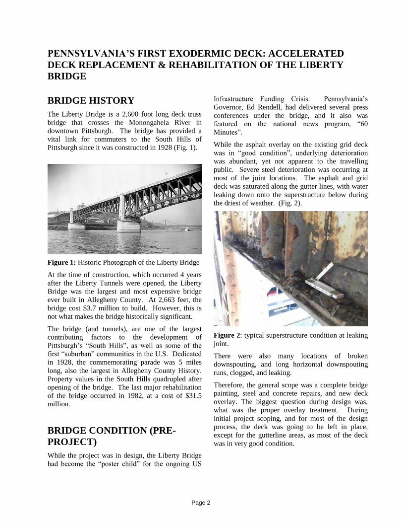
The Liberty Bridge is a 2,600 foot long deck truss
bridge that crosses the Monongahela River in
downtown Pittsburgh. The bridge has provided a
vital link for commuters to the South Hills of
Pittsburgh since it was constructed in 1928 (Fig. 1).
Figure 1: Historic Photograph of the Liberty Bridge
At the time of construction, which occurred 4 years
after the Liberty Tunnels were opened, the Liberty
Bridge was the largest and most expensive bridge
ever built in Allegheny County. At 2,663 feet, the
bridge cost $3.7 million to build. However, this is
not what makes the bridge historically significant.
The bridge (and tunnels), are one of the largest
contributing factors to the development of
Pittsburgh’s “South Hills”, as well as some of the
first “suburban” communities in the U.S. Dedicated
in 1928, the commemorating parade was 5 miles
long, also the largest in Allegheny County History.
Property values in the South Hills quadrupled after
opening of the bridge. The last major rehabilitation
of the bridge occurred in 1982, at a cost of $31.5
million.
BRIDGE CONDITION (PRE-
PROJECT)
While the project was in design, the Liberty Bridge
had become the “poster child” for the ongoing US
Infrastructure Funding Crisis. Pennsylvania’s
Governor, Ed Rendell, had delivered several press
conferences under the bridge, and it also was
featured on the national news program, “60
Minutes”.
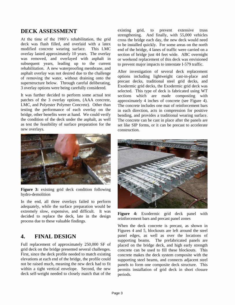
While the asphalt overlay on the existing grid deck
was in “good condition”, underlying deterioration
was abundant, yet not apparent to the travelling
public. Severe steel deterioration was occurring at
most of the joint locations. The asphalt and grid
deck was saturated along the gutter lines, with water
leaking down onto the superstructure below during
the driest of weather. (Fig. 2).
Figure 2: typical superstructure condition at leaking
joint.
There were also many locations of broken
downspouting, and long horizontal downspouting
runs, clogged, and leaking.
Therefore, the general scope was a complete bridge
painting, steel and concrete repairs, and new deck
overlay. The biggest question during design was,
what was the proper overlay treatment. During
initial project scoping, and for most of the design
process, the deck was going to be left in place,
except for the gutterline areas, as most of the deck
was in very good condition.
Page 2
DECK ASSESSMENT
At the time of the 1980’s rehabilitation, the grid
deck was flush filled, and overlaid with a latex
modified concrete wearing surface. This LMC
overlay lasted approximately 10 years. The overlay
was removed, and overlayed with asphalt in
subsequent years, leading up to the current
rehabilitation. A new waterproofing membrane, and
asphalt overlay was not desired due to the challenge
of removing the water, without draining onto the
superstructure below. Through careful deliberating,
3 overlay options were being carefully considered.
It was further decided to perform some actual test
patches of the 3 overlay options, (AAA concrete,
LMC, and Polyester Polymer Concrete). Other than
testing the performance of each overlay on the
bridge, other benefits were at hand. We could verify
the condition of the deck under the asphalt, as well
as test the feasibility of surface preparation for the
new overlays.
Figure 3: existing grid deck condition following
hydro-demolition
In the end, all three overlays failed to perform
adequately, while the surface preparation would be
extremely slow, expensive, and difficult. It was
decided to replace the deck, late in the design
process due to these valuable findings.
4. FINAL DESIGN
Full replacement of approximately 250,000 SF of
grid deck on the bridge presented several challenges.
First, since the deck profile needed to match existing
elevations at each end of the bridge, the profile could
not be raised much, meaning the new deck had to fit
within a tight vertical envelope. Second, the new
deck self-weight needed to closely match that of the
existing grid, to prevent extensive truss
strengthening. And finally, with 55,000 vehicles
cross the bridge each day, the new deck would need
to be installed quickly. For some areas on the north
end of the bridge, 4 lanes of traffic were carried on a
section of bridge just 44 feet wide. ABC overnight
or weekend replacement of this deck was envisioned
to prevent major impacts to interstate I-579 traffic.
After investigation of several deck replacement
options including lightweight cast-in-place and
precast decks, traditional steel grid decks, and
Exodermic grid decks, the Exodermic grid deck was
selected. This type of deck is fabricated using WT
sections which are made composting with
approximately 4 inches of concrete (see Figure 4).
The concrete includes one mat of reinforcement bars
in each direction, acts in compression for positive
bending, and provides a traditional wearing surface.
The concrete can be cast in place after the panels are
set like SIP forms, or it can be precast to accelerate
construction.
Figure 4: Exodermic grid deck panel with
reinforcement bars and precast panel zones
When the deck concrete is precast, as shown in
Figures 4 and 5, blockouts are left around the steel
panel edges, as well as over the locations of
supporting beams. The prefabricated panels are
placed on the bridge deck, and high early strength
concrete can be used to fill these blockouts. This
concrete makes the deck system composite with the
supporting steel beams, and connects adjacent steel
panels to form one composite deck structure. This
permits installation of grid deck in short closure
periods.
Page 3
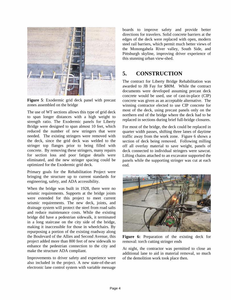
Figure 5: Exodermic grid deck panel with precast
zones assembled on the bridge
The use of WT sections allows this type of grid deck
to span longer distances with a high weight to
strength ratio. The Exodermic panels for Liberty
Bridge were designed to span almost 10 feet, which
reduced the number of new stringers that were
needed. The existing stringers were removed with
the deck, since the grid deck was welded to the
stringer top flanges prior to being filled with
concrete. By removing these stringers, many repairs
for section loss and poor fatigue details were
eliminated, and the new stringer spacing could be
optimized for the Exodermic grid deck.
Primary goals for the Rehabilitation Project were
bringing the structure up to current standards for
engineering, safety, and ADA accessibility.
When the bridge was built in 1928, there were no
seismic requirements. Supports at the bridge joints
were extended for this project to meet current
seismic requirements. The new deck, joints, and
drainage system will protect the steel from road salts
and reduce maintenance costs. While the existing
bridge did have a pedestrian sidewalk, it terminated
in a long staircase on the city side of the bridge,
making it inaccessible for those in wheelchairs. By
repurposing a portion of the existing roadway along
the Boulevard of the Allies and Second Avenue, this
project added more than 800 feet of new sidewalk to
enhance the pedestrian connection to the city and
make the structure ADA compliant.
Improvements to driver safety and experience were
also included in the project. A new state-of-the-art
electronic lane control system with variable message
boards to improve safety and provide better
directions for travelers. Solid concrete barriers at the
edges of the deck were replaced with open, modern
steel rail barriers, which permit much better views of
the Monongahela River valley, South Side, and
Pittsburgh skyline, improving driver experience of
this stunning urban view-shed.
5. CONSTRUCTION
The contract for Liberty Bridge Rehabilitation was
awarded to JB Fay for $80M. While the contract
documents were developed assuming precast deck
concrete would be used, use of cast-in-place (CIP)
concrete was given as an acceptable alternative. The
winning contractor elected to use CIP concrete for
most of the deck, using precast panels only on the
northern end of the bridge where the deck had to be
replaced in sections during brief full-bridge closures.
For most of the bridge, the deck could be replaced in
quarter width passes, shifting three lanes of daytime
traffic away from the work zone. Figure 6 shows a
section of deck being removed. Following milling
off all overlay material to save weight, panels of
deck connected to individual stringers were sawcut.
Lifting chains attached to an excavator supported the
panels while the supporting stringer was cut at each
end.
Figure 6: Preparation of the existing deck for
removal: torch cutting stringer ends
At night, the contractor was permitted to close an
additional lane to aid in material removal, so much
of the demolition work took place then.
Page 4
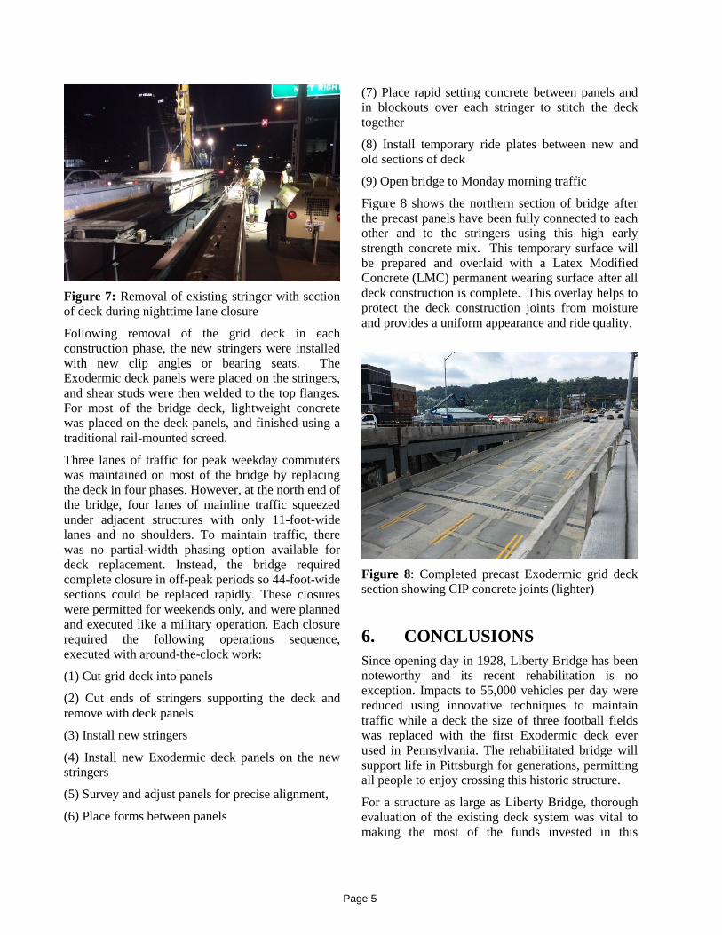
Figure 7: Removal of existing stringer with section
of deck during nighttime lane closure
Following removal of the grid deck in each
construction phase, the new stringers were installed
with new clip angles or bearing seats. The
Exodermic deck panels were placed on the stringers,
and shear studs were then welded to the top flanges.
For most of the bridge deck, lightweight concrete
was placed on the deck panels, and finished using a
traditional rail-mounted screed.
Three lanes of traffic for peak weekday commuters
was maintained on most of the bridge by replacing
the deck in four phases. However, at the north end of
the bridge, four lanes of mainline traffic squeezed
under adjacent structures with only 11-foot-wide
lanes and no shoulders. To maintain traffic, there
was no partial-width phasing option available for
deck replacement. Instead, the bridge required
complete closure in off-peak periods so 44-foot-wide
sections could be replaced rapidly. These closures
were permitted for weekends only, and were planned
and executed like a military operation. Each closure
required the following operations sequence,
executed with around-the-clock work:
(1) Cut grid deck into panels
(2) Cut ends of stringers supporting the deck and
remove with deck panels
(3) Install new stringers
(4) Install new Exodermic deck panels on the new
stringers
(5) Survey and adjust panels for precise alignment,
(6) Place forms between panels
(7) Place rapid setting concrete between panels and
in blockouts over each stringer to stitch the deck
together
(8) Install temporary ride plates between new and
old sections of deck
(9) Open bridge to Monday morning traffic
Figure 8 shows the northern section of bridge after
the precast panels have been fully connected to each
other and to the stringers using this high early
strength concrete mix. This temporary surface will
be prepared and overlaid with a Latex Modified
Concrete (LMC) permanent wearing surface after all
deck construction is complete. This overlay helps to
protect the deck construction joints from moisture
and provides a uniform appearance and ride quality.
Figure 8: Completed precast Exodermic grid deck
section showing CIP concrete joints (lighter)
6. CONCLUSIONS
Since opening day in 1928, Liberty Bridge has been
noteworthy and its recent rehabilitation is no
exception. Impacts to 55,000 vehicles per day were
reduced using innovative techniques to maintain
traffic while a deck the size of three football fields
was replaced with the first Exodermic deck ever
used in Pennsylvania. The rehabilitated bridge will
support life in Pittsburgh for generations, permitting
all people to enjoy crossing this historic structure.
For a structure as large as Liberty Bridge, thorough
evaluation of the existing deck system was vital to
making the most of the funds invested in this
Page 5
structure. Through a detailed test patch installation
and evaluation program, it was evident that trying to
patch and persevere the existing deck system was
not a wise long-term solution. The project team was
able to identify a modular deck system that
permitted Accelerated Bridge Construction (ABC),
while meeting the weight and geometric constraints
of a bridge rehabilitation.
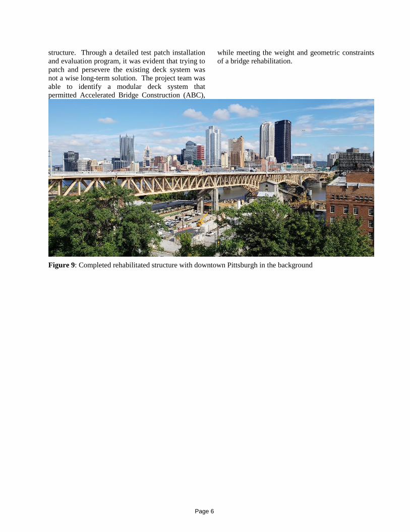
Figure 9: Completed rehabilitated structure with downtown Pittsburgh in the background
Page 6