Embed Size (px)
Citation preview
PennCOSYVIO: A Challenging Visual Inertial Odometry Benchmark
Bernd Pfrommer1 Nitin Sanket1 Kostas Daniilidis1 Jonas Cleveland2
Abstract— We present PennCOSYVIO, a new challengingVisual Inertial Odometry (VIO) benchmark with synchronizeddata from a VI-sensor (stereo camera and IMU), two ProjectTango hand-held devices, and three GoPro Hero 4 cameras.Recorded at UPenn’s Singh center, the 150m long path of thehand-held rig crosses from outdoors to indoors and includesrapid rotations, thereby testing the abilities of VIO and Simulta-neous Localization and Mapping (SLAM) algorithms to handlechanges in lighting, different textures, repetitive structures,and large glass surfaces. All sensors are synchronized andintrinsically and extrinsically calibrated. We demonstrate theaccuracy with which ground-truth poses can be obtained viaoptic localization off of fiducial markers. The data set can befound at https://daniilidis-group.github.io/penncosyvio/.
I. INTRODUCTION
In this paper we present a new, challenging data set aimedat benchmarking and supporting the development of newVisual Inertial Odometry (VIO) algorithms.
Originating from the Greek words “odos” (way) and“metron” (measure), odometry is the art and science ofestimating traveled distances based on sensor readings. Awide variety of different sensors can be used for this purpose,including global positioning system (GPS) receivers, laserrange finders, radio frequency (RF) receivers, sonar, camerasand Inertial Measurement Units (IMUs), with VIO beingbased on the latter two. The key challenge lies in developingalgorithms that efficiently fuse multi-sensory data [1] [2]and estimate the device’s motion as quickly and preciselyas possible, often also simultaneously building a map of theenvironment (SLAM) [3]. A great amount of research hasbeen done in this area, lately motivated by the race to buildautonomous cars [4] [5] and aerial vehicles [6] [7].
Most recently, augmented reality is coming to cell phones[8], hand-held devices such as Google’s Project Tango [9],and head-mounted displays, creating urgent demand forextraordinarily accurate odometry and head tracking in orderfor augmented reality objects to remain stationary when usersmove. Pure visual odometry [10] [11] [12] [13] [14] hasenjoyed considerable success, but at the moment, VIO basedon the fusion of camera (to eliminate drift and establish loopclosure) and IMU data (for rapid rotations) [15] [16] [17]appears to be the most promising approach.
In this context we present a VIO benchmark for which wesimultaneously record a number of different camera and IMUstreams, including data from two hand-held Google Project
1University of Pennsylvania School of Engineering and Applied Science2Cognitive Operational Systems, LLCFinancial support by the I/UCRC Rose-Hub NSF-IIP-1439681 and the
ARL RCTA W911NF-10-2-0016 is gratefully acknowledged.
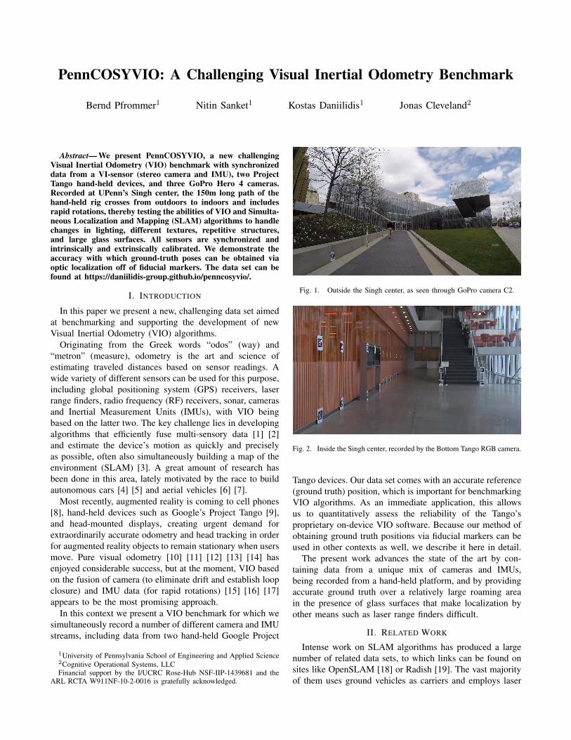
Fig. 1. Outside the Singh center, as seen through GoPro camera C2.
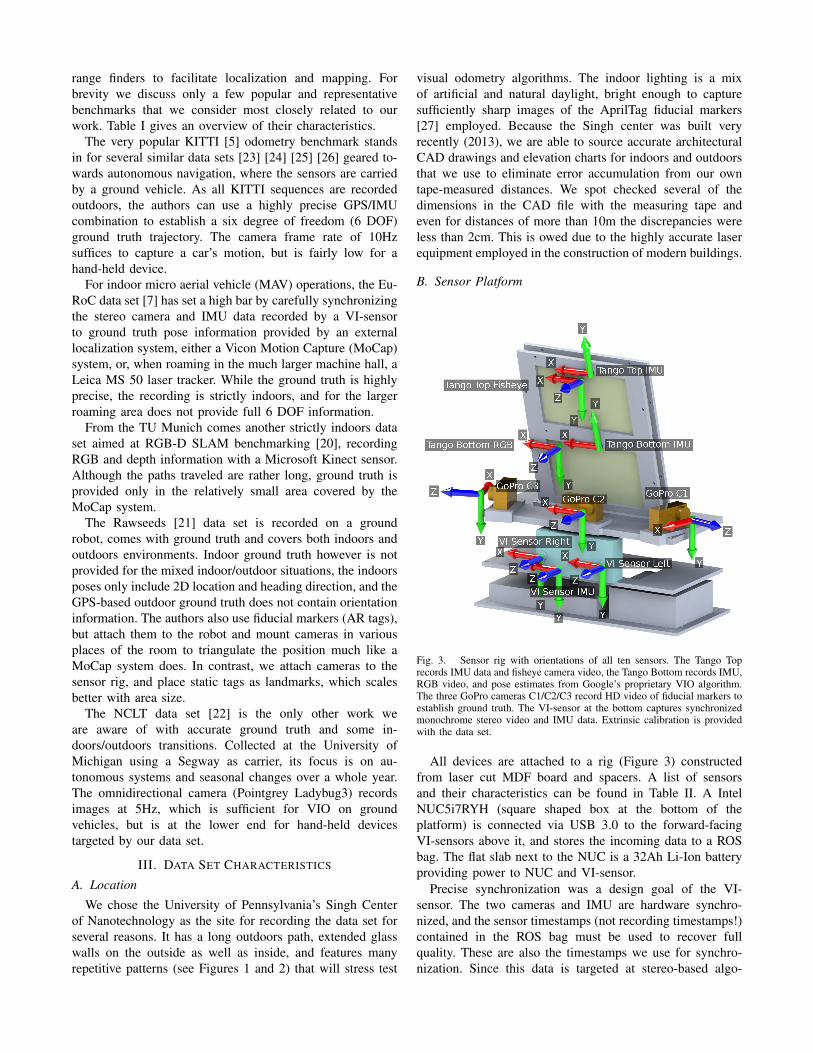
Fig. 2. Inside the Singh center, recorded by the Bottom Tango RGB camera.
Tango devices. Our data set comes with an accurate reference(ground truth) position, which is important for benchmarkingVIO algorithms. As an immediate application, this allowsus to quantitatively assess the reliability of the Tango’sproprietary on-device VIO software. Because our method ofobtaining ground truth positions via fiducial markers can beused in other contexts as well, we describe it here in detail.
The present work advances the state of the art by con-taining data from a unique mix of cameras and IMUs,being recorded from a hand-held platform, and by providingaccurate ground truth over a relatively large roaming areain the presence of glass surfaces that make localization byother means such as laser range finders difficult.
II. RELATED WORK
Intense work on SLAM algorithms has produced a largenumber of related data sets, to which links can be found onsites like OpenSLAM [18] or Radish [19]. The vast majorityof them uses ground vehicles as carriers and employs laser
range finders to facilitate localization and mapping. Forbrevity we discuss only a few popular and representativebenchmarks that we consider most closely related to ourwork. Table I gives an overview of their characteristics.
The very popular KITTI [5] odometry benchmark standsin for several similar data sets [23] [24] [25] [26] geared to-wards autonomous navigation, where the sensors are carriedby a ground vehicle. As all KITTI sequences are recordedoutdoors, the authors can use a highly precise GPS/IMUcombination to establish a six degree of freedom (6 DOF)ground truth trajectory. The camera frame rate of 10Hzsuffices to capture a car’s motion, but is fairly low for ahand-held device.
For indoor micro aerial vehicle (MAV) operations, the Eu-RoC data set [7] has set a high bar by carefully synchronizingthe stereo camera and IMU data recorded by a VI-sensorto ground truth pose information provided by an externallocalization system, either a Vicon Motion Capture (MoCap)system, or, when roaming in the much larger machine hall, aLeica MS 50 laser tracker. While the ground truth is highlyprecise, the recording is strictly indoors, and for the largerroaming area does not provide full 6 DOF information.
From the TU Munich comes another strictly indoors dataset aimed at RGB-D SLAM benchmarking [20], recordingRGB and depth information with a Microsoft Kinect sensor.Although the paths traveled are rather long, ground truth isprovided only in the relatively small area covered by theMoCap system.
The Rawseeds [21] data set is recorded on a groundrobot, comes with ground truth and covers both indoors andoutdoors environments. Indoor ground truth however is notprovided for the mixed indoor/outdoor situations, the indoorsposes only include 2D location and heading direction, and theGPS-based outdoor ground truth does not contain orientationinformation. The authors also use fiducial markers (AR tags),but attach them to the robot and mount cameras in variousplaces of the room to triangulate the position much like aMoCap system does. In contrast, we attach cameras to thesensor rig, and place static tags as landmarks, which scalesbetter with area size.
The NCLT data set [22] is the only other work weare aware of with accurate ground truth and some in-doors/outdoors transitions. Collected at the University ofMichigan using a Segway as carrier, its focus is on au-tonomous systems and seasonal changes over a whole year.The omnidirectional camera (Pointgrey Ladybug3) recordsimages at 5Hz, which is sufficient for VIO on groundvehicles, but is at the lower end for hand-held devicestargeted by our data set.
III. DATA SET CHARACTERISTICS
A. Location
We chose the University of Pennsylvania’s Singh Centerof Nanotechnology as the site for recording the data set forseveral reasons. It has a long outdoors path, extended glasswalls on the outside as well as inside, and features manyrepetitive patterns (see Figures 1 and 2) that will stress test
visual odometry algorithms. The indoor lighting is a mixof artificial and natural daylight, bright enough to capturesufficiently sharp images of the AprilTag fiducial markers[27] employed. Because the Singh center was built veryrecently (2013), we are able to source accurate architecturalCAD drawings and elevation charts for indoors and outdoorsthat we use to eliminate error accumulation from our owntape-measured distances. We spot checked several of thedimensions in the CAD file with the measuring tape andeven for distances of more than 10m the discrepancies wereless than 2cm. This is owed due to the highly accurate laserequipment employed in the construction of modern buildings.
B. Sensor Platform
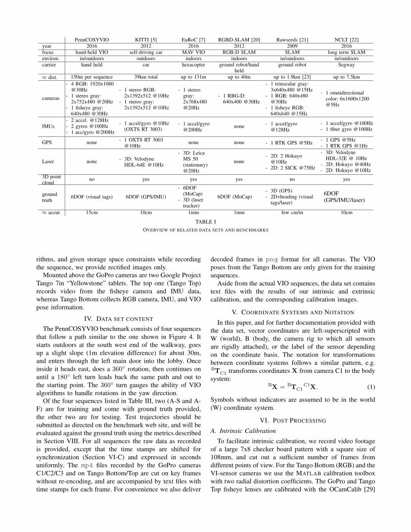
Fig. 3. Sensor rig with orientations of all ten sensors. The Tango Toprecords IMU data and fisheye camera video, the Tango Bottom records IMU,RGB video, and pose estimates from Google’s proprietary VIO algorithm.The three GoPro cameras C1/C2/C3 record HD video of fiducial markers toestablish ground truth. The VI-sensor at the bottom captures synchronizedmonochrome stereo video and IMU data. Extrinsic calibration is providedwith the data set.
All devices are attached to a rig (Figure 3) constructedfrom laser cut MDF board and spacers. A list of sensorsand their characteristics can be found in Table II. A IntelNUC5i7RYH (square shaped box at the bottom of theplatform) is connected via USB 3.0 to the forward-facingVI-sensors above it, and stores the incoming data to a ROSbag. The flat slab next to the NUC is a 32Ah Li-Ion batteryproviding power to NUC and VI-sensor.
Precise synchronization was a design goal of the VI-sensor. The two cameras and IMU are hardware synchro-nized, and the sensor timestamps (not recording timestamps!)contained in the ROS bag must be used to recover fullquality. These are also the timestamps we use for synchro-nization. Since this data is targeted at stereo-based algo-
PennCOSYVIO KITTI [5] EuRoC [7] RGBD-SLAM [20] Rawseeds [21] NCLT [22]year 2016 2012 2016 2012 2009 2016focus hand-held VIO self-driving car MAV VIO RGB-D SLAM SLAM long term SLAMenviron. in/outdoors outdoors indoors indoors in/outdoors in/outdoorscarrier hand held car hexacopter ground robot/hand
heldground robot Segway
≈ dist. 150m per sequence 39km total up to 131m up to 40m up to 1.9km [23] up to 7.5km
cameras
- 4 RGB: 1920x1080@30Hz
- 1 stereo gray:2x752x480 @20Hz
- 1 fisheye gray:640x480 @30Hz
- 1 stereo RGB:2x1392x512 @10Hz
- 1 stereo gray:2x1392x512 @10Hz
- 1 stereogray:2x768x480@20Hz
- 1 RBG-D:640x400 @30Hz
- 1 trinocular gray:3x640x480 @15Hz
- 1 RGB: 640x480@30Hz
- 1 fisheye RGB:640x640 @15Hz
- 1 omnidirectionalcolor: 6x1600x1200@5Hz
IMUs- 2 accel. @128Hz- 2 gyros @100Hz- 1 acc/gyro @200Hz
- 1 accel/gyro @10Hz(OXTS RT 3003)
- 1 accel/gyro@200Hz
none - 1 accel/gyro@128Hz
- 1 accel/gyro @100Hz- 1 fiber gyro @100Hz
GPS none - 1 OXTS RT 3003@10Hz
none none - 1 RTK GPS @5Hz - 1 GPS @5Hz- 1 RTK GPS @1Hz
Laser none - 3D: VelodyneHDL-64E @10Hz
- 3D: LeicaMS 50(stationary)@20Hz
none- 2D: 2 Hokuyo
@10Hz- 2D: 2 SICK @75Hz
- 3D: VelodyneHDL-32E @ 10Hz
- 2D: Hokuyo @40Hz- 2D: Hokuyo @10Hz
3D pointcloud
no yes yes yes no yes
groundtruth
6DOF (visual tags) 6DOF (GPS/IMU)
- 6DOF(MoCap)
- 3D (lasertracker)
6DOF (MoCap)- 3D (GPS)- 2D+heading (visual
tags/laser)
6DOF(GPS/IMU/laser)
≈ accur. 15cm 10cm 1mm 1mm few cm/m 10cm
TABLE IOVERVIEW OF RELATED DATA SETS AND BENCHMARKS
rithms, and given storage space constraints while recordingthe sequence, we provide rectified images only.
Mounted above the GoPro cameras are two Google ProjectTango 7in “Yellowstone” tablets. The top one (Tango Top)records video from the fisheye camera and IMU data,whereas Tango Bottom collects RGB camera, IMU, and VIOpose information.
IV. DATA SET CONTENT
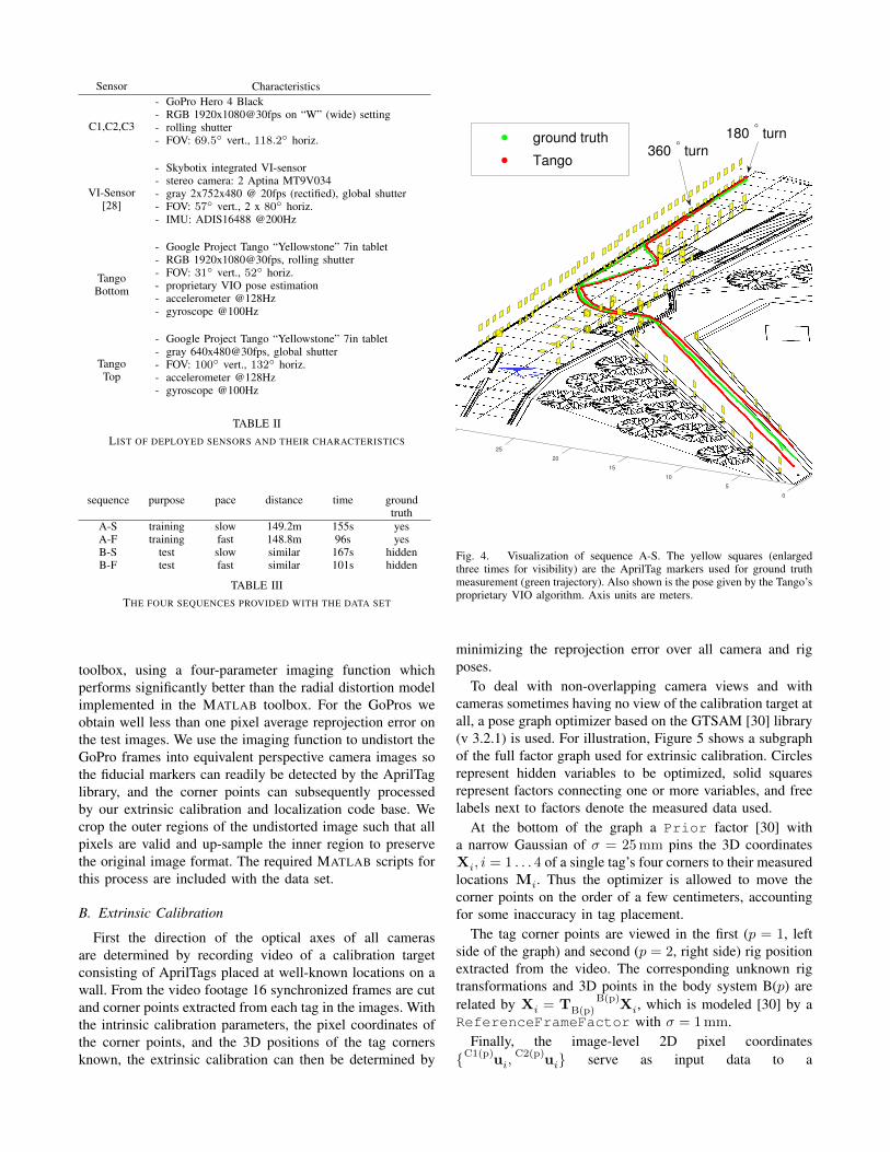
The PennCOSYVIO benchmark consists of four sequencesthat follow a path similar to the one shown in Figure 4. Itstarts outdoors at the south west end of the walkway, goesup a slight slope (1m elevation difference) for about 30m,and enters through the left main door into the lobby. Onceinside it heads east, does a 360◦ rotation, then continues onuntil a 180◦ left turn leads back the same path and out tothe starting point. The 360◦ turn gauges the ability of VIOalgorithms to handle rotations in the yaw direction.
Of the four sequences listed in Table III, two (A-S and A-F) are for training and come with ground truth provided,the other two are for testing. Test trajectories should besubmitted as directed on the benchmark web site, and will beevaluated against the ground truth using the metrics describedin Section VIII. For all sequences the raw data as recordedis provided, except that the time stamps are shifted forsynchronization (Section VI-C) and expressed in secondsuniformly. The mp4 files recorded by the GoPro camerasC1/C2/C3 and on Tango Bottom/Top are cut on key frameswithout re-encoding, and are accompanied by text files withtime stamps for each frame. For convenience we also deliver
decoded frames in png format for all cameras. The VIOposes from the Tango Bottom are only given for the trainingsequences.
Aside from the actual VIO sequences, the data set containstext files with the results of our intrinsic and extrinsiccalibration, and the corresponding calibration images.
V. COORDINATE SYSTEMS AND NOTATION
In this paper, and for further documentation provided withthe data set, vector coordinates are left-superscripted withW (world), B (body, the camera rig to which all sensorsare rigidly attached), or the label of the sensor dependingon the coordinate basis. The notation for transformationsbetween coordinate systems follows a similar pattern, e.g.TB
C1 transforms coordinates X from camera C1 to the bodysystem:
XB = TBC1 XC1 . (1)
Symbols without indicators are assumed to be in the world(W) coordinate system.
VI. POST PROCESSING
A. Intrinsic Calibration
To facilitate intrinsic calibration, we record video footageof a large 7x8 checker board pattern with a square size of108mm, and cut out a sufficient number of frames fromdifferent points of view. For the Tango Bottom (RGB) and theVI-sensor cameras we use the MATLAB calibration toolboxwith two radial distortion coefficients. The GoPro and TangoTop fisheye lenses are calibrated with the OCamCalib [29]
Sensor Characteristics
C1,C2,C3
- GoPro Hero 4 Black- RGB 1920x1080@30fps on “W” (wide) setting- rolling shutter- FOV: 69.5◦ vert., 118.2◦ horiz.
VI-Sensor[28]
- Skybotix integrated VI-sensor- stereo camera: 2 Aptina MT9V034- gray 2x752x480 @ 20fps (rectified), global shutter- FOV: 57◦ vert., 2 x 80◦ horiz.- IMU: ADIS16488 @200Hz
TangoBottom
- Google Project Tango “Yellowstone” 7in tablet- RGB 1920x1080@30fps, rolling shutter- FOV: 31◦ vert., 52◦ horiz.- proprietary VIO pose estimation- accelerometer @128Hz- gyroscope @100Hz
TangoTop
- Google Project Tango “Yellowstone” 7in tablet- gray 640x480@30fps, global shutter- FOV: 100◦ vert., 132◦ horiz.- accelerometer @128Hz- gyroscope @100Hz
TABLE IILIST OF DEPLOYED SENSORS AND THEIR CHARACTERISTICS
sequence purpose pace distance time groundtruth
A-S training slow 149.2m 155s yesA-F training fast 148.8m 96s yesB-S test slow similar 167s hiddenB-F test fast similar 101s hidden
TABLE IIITHE FOUR SEQUENCES PROVIDED WITH THE DATA SET
toolbox, using a four-parameter imaging function whichperforms significantly better than the radial distortion modelimplemented in the MATLAB toolbox. For the GoPros weobtain well less than one pixel average reprojection error onthe test images. We use the imaging function to undistort theGoPro frames into equivalent perspective camera images sothe fiducial markers can readily be detected by the AprilTaglibrary, and the corner points can subsequently processedby our extrinsic calibration and localization code base. Wecrop the outer regions of the undistorted image such that allpixels are valid and up-sample the inner region to preservethe original image format. The required MATLAB scripts forthis process are included with the data set.
B. Extrinsic Calibration
First the direction of the optical axes of all camerasare determined by recording video of a calibration targetconsisting of AprilTags placed at well-known locations on awall. From the video footage 16 synchronized frames are cutand corner points extracted from each tag in the images. Withthe intrinsic calibration parameters, the pixel coordinates ofthe corner points, and the 3D positions of the tag cornersknown, the extrinsic calibration can then be determined by
25
20
15
10
5
0
ground truth
Tango
180° turn
360° turn
Fig. 4. Visualization of sequence A-S. The yellow squares (enlargedthree times for visibility) are the AprilTag markers used for ground truthmeasurement (green trajectory). Also shown is the pose given by the Tango’sproprietary VIO algorithm. Axis units are meters.
minimizing the reprojection error over all camera and rigposes.
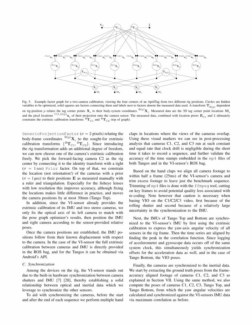
To deal with non-overlapping camera views and withcameras sometimes having no view of the calibration target atall, a pose graph optimizer based on the GTSAM [30] library(v 3.2.1) is used. For illustration, Figure 5 shows a subgraphof the full factor graph used for extrinsic calibration. Circlesrepresent hidden variables to be optimized, solid squaresrepresent factors connecting one or more variables, and freelabels next to factors denote the measured data used.
At the bottom of the graph a Prior factor [30] witha narrow Gaussian of σ = 25 mm pins the 3D coordinatesXi, i = 1 . . . 4 of a single tag’s four corners to their measuredlocations Mi. Thus the optimizer is allowed to move thecorner points on the order of a few centimeters, accountingfor some inaccuracy in tag placement.
The tag corner points are viewed in the first (p = 1, leftside of the graph) and second (p = 2, right side) rig positionextracted from the video. The corresponding unknown rigtransformations and 3D points in the body system B(p) arerelated by Xi = TB(p) X
B(p)i, which is modeled [30] by a
ReferenceFrameFactor with σ = 1 mm.Finally, the image-level 2D pixel coordinates
{ uC1(p)
i, uC2(p)
i} serve as input data to a
XB(1)
1 XB(1)
2 XB(1)
3 XB(1)
4 XB(2)
1 XB(2)
2 XB(2)
3 XB(2)
4
TBC1 TB
C2
TB(1) TB(2)
X1 X2 X3 X4
uC1(1)
1 uC1(1)
2 uC1(1)
3 uC1(1)
4uC2(1)
1 uC2(1)
2 uC2(1)
3 uC2(1)
4 uC1(2)
1 uC1(2)
2 uC1(2)
3 uC1(2)
4uC2(2)
1 uC2(2)
2 uC2(2)
3 uC2(2)
4
1EC1
M1 M2 M3 M4
Fig. 5. Example factor graph for a two-camera calibration, viewing the four corners of an AprilTag from two different rig positions. Circles are hiddenvariables to be optimized, solid squares are factors connecting them and labels next to factors denote the measured data used. A transform T
B(p)dependent
on rig-position p relates the tag corner points Xi to their body-system coordinates XB(p)
i. Measured data are the 3D tag corner point locations Mi
and the pixel locations uC(1,2)(p)
i of their projection onto the camera sensor. The measured data, combined with location priors EC1 and 1 ultimatelyconstrains the extrinsic calibration transforms TB
C1 and TBC2 (top of graph).
GenericProjectionFactor (σ = 2 pixels) relating thebody-frame coordinates X
B(p)i to the sought-for extrinsic
calibration transforms { TBC1, TB
C2}. Since introducingthe rig transformation adds an additional degree of freedom,we can now choose one of the camera’s extrinsic calibrationfreely. We pick the forward-facing camera C2 as the rigcenter by connecting it to the identity transform with a tight(σ = 1 nm) Prior factor. On top of that, we constrainthe location (not orientation!) of the cameras with a prior(σ = 1 µm) to their positions E as measured manually witha ruler and triangulation. Especially for the fisheye lenseswith low resolution this improves accuracy, although fixingthe locations makes little difference in practice, and movesthe camera positions by at most 30mm (Tango Top).
In addition, since the VI-sensor already provides theextrinsic calibration of its IMU and two stereo cameras, weonly fix the optical axis of its left camera to match withthe pose graph optimizer’s results, then position the IMUand right camera according to the sensor-provided relativeposes.
Once the camera positions are established, the IMU po-sitions follow from their known displacement with respectto the camera. In the case of the VI-sensor the full extrinsiccalibration between cameras and IMU is directly providedin the ROS bag, and for the Tangos it can be obtained viaAndroid’s API.
C. Synchronization
Among the devices on the rig, the VI-sensor stands outdue to the built-in hardware synchronization between camerashutters and IMU [7] [28], thereby establishing a solidrelationship between optical and inertial data which weleverage to synchronize the other sensors.
To aid with synchronizing the cameras, before the startand after the end of each sequence we perform multiple hand
claps in locations where the views of the cameras overlap.Using these visual markers we can see in post-processinganalysis that cameras C1, C2, and C3 run at such constantand equal rate that clock drift is negligible during the shorttime it takes to record a sequence, and further validate theaccuracy of the time stamps embedded in the mp4 files ofboth Tangos and in the VI-sensor’s ROS bag.
Based on the hand claps we align all camera footage towithin half a frame (25ms) of the VI-sensor’s camera andtrim excess footage to leave just the benchmark sequence.Trimming of mp4 files is done with the ffmpeg tool, cuttingon key frames to avoid potential quality loss associated withre-coding. Note however that caution is necessary whenbasing VIO on the C1/C2/C3 video, first because of therolling shutter and second because of a relatively largeuncertainty in the synchronization to the IMU.
Next, the IMUs of Tango Top and Bottom are synchro-nized to the VI-sensor’s IMU by first using the extrinsiccalibration to express the yaw-axis angular velocity of allsensors in the rig frame. Then the time series are aligned byfinding the peak in the correlation function. Since loggingof accelerometer and gyroscope data occurs off of the samesystem clock, this simultaneously yields synchronizationoffsets for the acceleration data as well, and in the case ofTango Bottom, the VIO poses.
Finally, the cameras are synchronized to the inertial data.We start by extracting the ground truth poses from the frame-accuracy aligned footage of cameras C1, C2, and C3 asexplained in Section VII. Using the same method, we alsocompute the poses of cameras C1, C2, C3, Tango Top, andTango Bottom, from which the yaw angular velocities arecalculated and synchronized against the VI-sensors IMU datavia maximum correlation as before.

VII. GROUND TRUTH
A. Method
Our ground truth poses are obtained by recording imagesof fiducial markers with cameras C1, C2, and C3. The GoProcameras’ optical axes are all in the horizontal plane, and areoffset by an angle of about 75◦ about the vertical axis (seeFigure 3), resulting in a combined horizontal field of viewof almost 270◦ (vertical FOV of 69.5◦) when recording in“W” (wide) mode at full HD (1920x1080). The wide FOV(along with a bubble level on the rig to keep it approximatelyhorizontal) ensures that a sufficient number of tags are visibleat any one point in time.
As fiducial markers we use AprilTags [27] of size 36h11,printed on letter size paper, and backed by 1/4in MDF boardwhere necessary. A total of 170 tags are placed as shownin Figure 4. Attention must be paid to place the tags suchthat they form triangles of sufficient height. For instance,placing tags just along the bottom of the stone wall at thewalkway is not sufficient. Additional tags must be placed atdifferent elevations, i.e. on the lamp posts, to yield accuratealtitude via triangulation. After placement, we measure theexact position of each tag with a measure tape and record it,along with its orientation. That many tags are placed alongprecisely built walls expedites this process. Placing all tags,measuring and noting their locations, and recording the videosequence can be accomplished by two persons in a single 10hday.
After the sequence is recorded, the mp4 video files aredownloaded from the cameras and synchronized (see SectionVI-C). With the help of the AprilTag library [27] we extractfor all three cameras k ∈ {C1,C2,C3} the pixel coordinates
uk(p) j
i of the four corner points i = 1 . . . 4 belonging to tagj in each frame p, and via the tag identity relate them to themeasured 3D corner coordinates Mj
i in the world referenceframe.
We can now determine the ground truth poses of the rigvia maximum likelihood estimation over a pose graph usingthe GTSAM [30] library in a similar fashion as for theextrinsic calibration in Section VI-B. An example of thegraph structure is shown in Figure 6. For simplicity, onlya single tag is visible here, allowing us to drop the tag indexj. At the bottom of the graph, a narrow PriorFactor[30] of σ = 25 mm constrains the 3D corner coordinates Xi
of a single tag to their physically measured values Mi. Thecorresponding observed 2D pixel coordinates u
k(p)i in frame
p then impose constraints via a ProjectionFactor (σ =2 pixels) on the pose Tk(p) of the observing camera, whichin turn establishes the rig pose TB(p) through the known ex-trinsic calibration transforms TB
k with uncertainties chosento be σrot = 3◦ (rotation) and σtrans = 10 mm (translation).
The rig poses TB(p) are interconnected with an identitytransform (σrot = 11◦, σtrans = 50 mm) that smoothsbetween frames and fills in rig poses in the rare occasionwhen none of the three cameras observes a tag.
B. Accuracy Tests
Because the camera path includes outdoors scenes, anddue to the large area covered, using a MoCap system forground truth verification as in reference [7] is not possible.Instead, similar to [21] we conducted experiments to estimatethe accuracy of our ground truth. For this purpose, the camerarig was placed on a dolly that was guided along a 2 m longrail at three different places (one outdoors and two indoors),traveling parallel to walls so the orientation of the test pathwas well established. After rotating and shifting the groundtruth to align with the starting point of the test path, theground truth motion should be strictly in the longitudinal xdirection, with no movement in y and z. Figure 7 showsthe observed error in the horizontal y direction and theelevation z (upper graph), and an indicator of visible tags(lower graph). The peak-to-peak error observed for outdoorsis ∆y = 50 mm and ∆z = 17 mm. Notice the fluctuationof the y error caused by the presence or absence of close-bytag #90. For the same experiment conducted at two differentindoors locations along the path we find ∆y = 31 mm,∆z = 16 mm (open lobby, near display) and ∆y = 16 mm,∆z = 9 mm (near location of 360◦ turn).
To put these errors into perspective, Figure 7 also plotsthe errors in the position estimate of the Google Tango asobtained from its proprietary VIO algorithm. The errors aregenerally about four times larger than for the ground truth,and until loop closure occurs, are expected to show someaccumulation.
Without exhaustive tests along the whole path it is difficultto put a strict bound on the accuracy of the ground truth rigposes. The covariances from the pose graph estimator yield amean error of 2.5 cm for the position and 3.5◦ for the angle.We estimate that our ground truth position is accurate tobetter than 10 cm along most of the path, with inaccuraciespossibly rising to 15 cm near the beginning and end of thepath, where tags are spread more sparsely.
VIII. EVALUATION METRIC
There are several different ways [5] [20] [31] to evaluatethe quality of a trajectory with respect to the ground truth.Closely following reference [20] we adopt two of them, theAbsolute Trajectory Error (ATE), and the Relative Pose Error(RPE). While they are qualitatively often similar [20], theymeasure accuracy at different length scales. ATE is the moreintuitive variant and more relevant for e.g. augmented realityapplications because it measures the ability to follow theentire length of the path without drift or rotational errors,making successful loop closure a necessity. RPE on theother hand measures the drift of the trajectory over somelength scale, and is used most prominently for the KITTIVO benchmark [5]. We will discuss both metrics below.
In general an odometry algorithm will produce an esti-mated trajectory P1:N that is a sequence of transformationsPi := TW′
B(i), describing the transition from body (rig)coordinate system B to an arbitrarily chosen world systemW ′ for a given frame i. This is to be compared to thecorresponding ground truth poses Qi := TW ref
B(i).
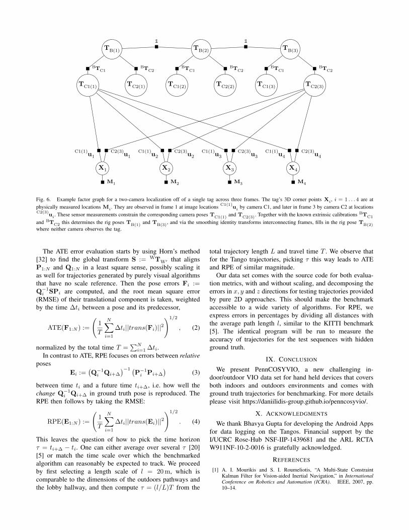
TC2(1)TC1(1) TC1(2) TC2(2) TC1(3) TC2(3)
TB(1) TB(2) TB(3)
X1 X2 X3 X4
uC1(1)
1 uC1(1)
2 uC1(1)
3 uC1(1)
4uC2(3)
1 uC2(3)
2 uC2(3)
3 uC2(3)
4
1 1
TBC1 TB
C2 TBC1 TB
C2 TBC1 TB
C2
M1 M2 M3 M4
Fig. 6. Example factor graph for a two-camera localization off of a single tag across three frames. The tag’s 3D corner points Xi, i = 1 . . . 4 are atphysically measured locations Mi. They are observed in frame 1 at image locations u
C1(1)i by camera C1, and later in frame 3 by camera C2 at locations
uC2(3)
i. These sensor measurements constrain the corresponding camera poses TC1(1)
and TC2(3)
. Together with the known extrinsic calibrations TBC1
and TBC2 this determines the rig poses T
B(1)and T
B(3), and via the smoothing identity transforms interconnecting frames, fills in the rig pose T
B(2)where neither camera observes the tag.
The ATE error evaluation starts by using Horn’s method[32] to find the global transform S := TW
W′ that alignsP1:N and Q1:N in a least square sense, possibly scaling itas well for trajectories generated by purely visual algorithmsthat have no scale reference. Then the pose errors Fi :=Q−1
i SPi are computed, and the root mean square error(RMSE) of their translational component is taken, weightedby the time ∆ti between a pose and its predecessor,
ATE(F1:N ) :=
(1
T
N∑i=1
∆ti||trans(Fi)||2)1/2
, (2)
normalized by the total time T =∑N
i=1 ∆ti.In contrast to ATE, RPE focuses on errors between relative
posesEi :=
(Q−1
i Qi+∆
)−1 (P−1
i Pi+∆
)(3)
between time ti and a future time ti+∆, i.e. how well thechange Q−1
i Qi+∆ in ground truth pose is reproduced. TheRPE then follows by taking the RMSE:
RPE(E1:N ) :=
(1
T
N∑i=1
∆ti||trans(Ei)||2)1/2
. (4)
This leaves the question of how to pick the time horizonτ = ti+∆ − ti. One can either average over several τ [20][5] or match the time scale over which the benchmarkedalgorithm can reasonably be expected to track. We proceedby first selecting a length scale of l = 20 m, which iscomparable to the dimensions of the outdoors pathways andthe lobby hallway, and then compute τ = (l/L)T from the
total trajectory length L and travel time T . We observe thatfor the Tango trajectories, picking τ this way leads to ATEand RPE of similar magnitude.
Our data set comes with the source code for both evalua-tion metrics, with and without scaling, and decomposing theerrors in x, y and z directions for testing trajectories providedby pure 2D approaches. This should make the benchmarkaccessible to a wide variety of algorithms. For RPE, weexpress errors in percentages by dividing all distances withthe average path length l, similar to the KITTI benchmark[5]. The identical program will be run to measure theaccuracy of trajectories for the test sequences with hiddenground truth.
IX. CONCLUSION
We present PennCOSYVIO, a new challenging in-door/outdoor VIO data set for hand held devices that coversboth indoors and outdoors environments and comes withground truth trajectories for benchmarking. For more detailsplease visit https://daniilidis-group.github.io/penncosyvio/.
X. ACKNOWLEDGMENTS
We thank Bhavya Gupta for developing the Android Appsfor data logging on the Tangos. Financial support by theI/UCRC Rose-Hub NSF-IIP-1439681 and the ARL RCTAW911NF-10-2-0016 is gratefully acknowledged.
REFERENCES
[1] A. I. Mourikis and S. I. Roumeliotis, “A Multi-State ConstraintKalman Filter for Vision-aided Inertial Navigation,” in InternationalConference on Robotics and Automation (ICRA). IEEE, 2007, pp.10–14.
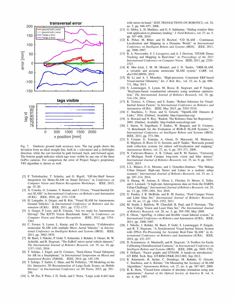
-150
-100
-50
0
50
100
150
200e
rror
[mm
]transversal error
ground truth y error
ground truth z error
Tango y error
Tango z error
0 500 1000 1500 2000
x position [mm]
78 79 80 90 91 92
109
tag id
tags visible
Fig. 7. Outdoors ground truth accuracy tests. The top graph shows thedeviation from an ideal straight line, both in z (elevation) and y (left/right)direction, while the cart traveled its path forward, back, and forward again.The bottom graph indicates which tags were visible by any one of the threeGoPro cameras. For comparison the error of Project Tango’s proprietaryVIO algorithm is shown as well.
[2] P. Tiefenbacher, T. Schulze, and G. Rigoll, “Off-the-Shelf SensorIntegration for Mono-SLAM on Smart Devices,” in Conference onComputer Vision and Pattern Recognition Workshops. IEEE, 2015,pp. 15–20.
[3] A. Concha, G. Loianno, V. Kumar, and J. Civera, “Visual-Inertial Di-rect SLAM,” in International Conference on Robotics and Automation(ICRA). IEEE, 2016, pp. 1331–1338.
[4] H. Lategahn, A. Geiger, and B. Kitt, “Visual SLAM for AutonomousGround Vehicles,” in International Conference on Robotics and Au-tomation (ICRA). IEEE, 2011, pp. 1732–1737.
[5] A. Geiger, P. Lenz, and R. Urtasun, “Are we ready for AutonomousDriving? The KITTI Vision Benchmark Suite,” in Conference onComputer Vision and Pattern Recognition. IEEE, 2012, pp. 3354–3361.
[6] C. Forster, S. Lynen, L. Kneip, and D. Scaramuzza, “Collaborativemonocular SLAM with multiple Micro Aerial Vehicles.” in Interna-tional Conference on Intelligent Robots and Systems (IROS). IEEE,2013, pp. 3962–3970.
[7] M. Burri, J. Nikolic, P. Gohl, T. Schneider, J. Rehder, S. Omari, M. W.Achtelik, and R. Siegwart, “The EuRoC micro aerial vehicle datasets,”The International Journal of Robotics Research, vol. 35, no. 10, pp.1157–1163, 2016.
[8] T. Schops, J. Engel, and D. Cremers, “Semi-Dense Visual Odometryfor AR on a Smartphone,” in International Symposium on Mixed andAugmented Reality (ISMAR). IEEE, 2014, pp. 145–150.
[9] T. Schops, T. Sattler, C. Hane, and M. Pollefeys, “3D Modeling on theGo: Interactive 3D Reconstruction of Large-Scale Scenes on MobileDevices,” in International Conference on 3D Vision, 2015, pp. 291–299.
[10] L. M. Paz, P. Pinis, J. D. Tards, and J. Neira, “Large scale 6-dof slam
with stereo-in-hand,” IEEE TRANSACTIONS ON ROBOTICS, vol. 24,no. 5, pp. 946–957, 2008.
[11] G. Sibley, L. H. Matthies, and G. S. Sukhatme, “Sliding window filterwith application to planetary landing.” J. Field Robotics, vol. 27, no. 5,pp. 587–608, 2010.
[12] K. Pirker, M. Rther, and H. Bischof, “CD SLAM - ContinuousLocalization and Mapping in a Dynamic World,” in InternationalConference on Intelligent Robots and Systems (IROS). IEEE, 2011,pp. 3990–3997.
[13] R. A. Newcombe, S. J. Lovegrove, and A. J. Davison, “DTAM: DenseTracking and Mapping in Real-time,” in Proceedings of the 2011International Conference on Computer Vision. IEEE, 2011, pp. 2320–2327.
[14] R. Mur-Artal, J. M. M. Montiel, and J. D. Tardos, “ORB-SLAM:a versatile and accurate monocular SLAM system,” CoRR, vol.abs/1502.00956, 2015.
[15] M. Li and A. I. Mourikis, “High-precision, Consistent EKF-basedVisual-inertial Odometry,” Int. J. Rob. Res., vol. 32, no. 6, pp. 690–711, May 2013.
[16] S. Leutenegger, S. Lynen, M. Bosse, R. Siegwart, and P. Furgale,“Keyframe-based visualinertial odometry using nonlinear optimiza-tion,” The International Journal of Robotics Research, vol. 34, pp.314–334, 2014.
[17] K. Tsotsos, A. Chiuso, and S. Soatto, “Robust Inference for Visual-Inertial Sensor Fusion,” in International Conference on Robotics andAutomation (ICRA). IEEE, May 2015, pp. 5203–5210.
[18] C. Stachniss, U. Frese, and G. Grisetti, “OpenSLAM: Datasets &Links,” 2016. [Online]. Available: http://openslam.org/
[19] A. Howard and N. Roy, “Radish: The Robotics Data Set Repository,”2003. [Online]. Available: http://radish.sourceforge.net/
[20] J. Sturm, N. Engelhard, F. Endres, W. Burgard, and D. Cremers,“A Benchmark for the Evaluation of RGB-D SLAM Systems,” inInternational Conference on Intelligent Robots and Systems (IROS).IEEE, 2012, pp. 573–580.
[21] S. Ceriani, G. Fontana, A. Giusti, D. Marzorati, M. Matteucci,D. Migliore, D. Rizzi, D. G. Sorrenti, and P. Taddei, “Rawseeds groundtruth collection systems for indoor self-localization and mapping,”Autonomous Robots, vol. 27, no. 4, pp. 353–371, 2009.
[22] N. Carlevaris-Bianco, A. K. Ushani, and R. M. Eustice, “Universityof Michigan North Campus long-term vision and lidar dataset,”International Journal of Robotics Research, vol. 35, no. 9, pp. 1023–1035, 2015.
[23] J.-L. Blanco, F.-A. Moreno, and J. Gonzalez-Jimenez, “The MalagaUrban Dataset: High-rate Stereo and Lidars in a realistic urbanscenario,” International Journal of Robotics Research, vol. 33, no. 2,pp. 207–214, 2014.
[24] A. Huang, M. Antone, E. Olson, L. Fletcher, D. Moore, S. Teller,and J. Leonard, “A high-rate, heterogeneous data set from the DARPAUrban Challenge,” International Journal of Robotics Research, vol. 29,no. 13, pp. 1595–1601, Nov 2010.
[25] G. Pandey, J. R. McBride, and R. M. Eustice, “Ford Campus Visionand Lidar Data Set,” International Journal of Robotics Research,vol. 30, no. 13, pp. 1543–1552, 2011.
[26] M. Smith, I. Baldwin, W. Churchill, R. Paul, and P. Newman, “TheNew College Vision and Laser Data Set,” The International Journalof Robotics Research, vol. 28, no. 5, pp. 595–599, May 2009.
[27] E. Olson, “AprilTag: A robust and flexible visual fiducial system,” inInternational Conference on Robotics and Automation (ICRA). IEEE,2011, pp. 3400–3407.
[28] J. Nikolic, J. Rehder, M. Burri, P. Gohl, S. Leutenegger, P. Furgale,and R. Y. Siegwart, “A Synchronized Visual-Inertial Sensor Systemwith FPGA Pre-Processing for Accurate Real-Time SLAM,” in In-ternational Conference on Robotics and Automation (ICRA). IEEE,2014, pp. 431–437.
[29] D. Scaramuzza, A. Martinelli, and R. Siegwart, “A Toolbox for EasilyCalibrating Omnidirectional Cameras,” in International Conference onIntelligent Robots and Systems (IROS). IEEE, 2006, pp. 5695–5701.
[30] F. Dellaert, “Factor graphs and GTSAM: A hands-on introduction,”GT RIM, Tech. Rep. GT-RIM-CP&R-2012-002, Sep 2012.
[31] R. Kummerle, B. Steder, C. Dornhege, M. Ruhnke, G. Grisetti,C. Stachniss, and A. Kleiner, “On Measuring the Accuracy of SLAMAlgorithms,” Autonomous Robots, vol. 27, no. 4, pp. 387–407, 2009.
[32] B. K. Horn, “Closed-form solution of absolute orientation using unitquaternions,” Journal of the Optical Society of America B, vol. 4,no. 4, Apr 1987.