Embed Size (px)
Citation preview

Penn State Ice Hockey Arena Thesis Final Report
Penn State Ice Hockey Arena Final Report
IPD/BIM Thesis 4/24/2012
Page 2 of 310 Joe Buyer Steve Conroe Logan Gray Simi Veit
Table of Contents
Executive Summary ............................................................................................................... 7
Main Arena Executive Summary .......................................................................................... 12
Structural Solution Executive Summary ............................................................................... 13
Main Arena Design Approach .............................................................................................. 16
Structural Roof System Concept ........................................................................................... 16
Structural Roof Components ................................................................................................ 18
Structural Student and an Integrated Approach ................................................................... 18
Design Results ..................................................................................................................... 19
........................................................................................................................................... 33
........................................................................................................................................... 33
........................................................................................................................................... 33
........................................................................................................................................... 33
........................................................................................................................................... 33
Mechanical Solution Executive Summary ............................................................................. 34
Lighting/Electrical Solution Executive Summary ................................................................... 51
Main Arena Design Approach .............................................................................................. 52
Lighting Platform Solution ................................................................................................... 53
Main Arena Event Lighting Solution ..................................................................................... 53
Main Arena Theatrical Lighting Solution .............................................................................. 56
Main Arena Total Illumination Solution - AGi32 Renderings ................................................. 58
........................................................................................................................................... 58
Main Arena 3D Studio Max Renderings ................................................................................ 59
........................................................................................................................................... 59
Main Arena Electrical Solution ............................................................................................. 60
........................................................................................................................................... 60
Main Arena Lighting and Electrical Conclusion ..................................................................... 61
........................................................................................................................................... 61

Penn State Ice Hockey Arena Final Report
IPD/BIM Thesis 4/24/2012
Page 3 of 310 Joe Buyer Steve Conroe Logan Gray Simi Veit
Main Arena Construction ..................................................................................................... 64
Main Arena Conclusion ........................................................................................................ 84
Design Intent for the East Facade ......................................................................................... 85
Structural Solution Executive Summary ............................................................................... 86
Structural Student and an Integrated Approach ................................................................... 88
Building Information Modeling ............................................................................................ 88
........................................................................................................................................... 88
Structural Design Process .................................................................................................... 89
......................................................................................................................................... 102
......................................................................................................................................... 102
Mechanical Solution Executive Summary ........................................................................... 103
Lighting/Electrical Solution Executive Summary ................................................................. 109
East Façade and Main Lobby Design Approach ................................................................... 110
East Façade Daylight Analysis ............................................................................................ 111
East Façade Interior Electric Lighting Solution .................................................................... 113
East Façade Exterior Lighting Solution ................................................................................ 118
......................................................................................................................................... 118
......................................................................................................................................... 119
......................................................................................................................................... 119
......................................................................................................................................... 119
East Façade Lighting and Electrical Conclusion ................................................................... 120
East Facade Construction ................................................................................................... 123
Conclusion for East Façade ................................................................................................ 132
......................................................................................................................................... 132
......................................................................................................................................... 132
Design Intent for the Community Rink ............................................................................... 133
Structural Solution Executive Summary ............................................................................. 134
Structural System Concept ................................................................................................. 136
Penn State Ice Hockey Arena Final Report
IPD/BIM Thesis 4/24/2012
Page 4 of 310 Joe Buyer Steve Conroe Logan Gray Simi Veit
Structural Design Process of Kingpost Truss ....................................................................... 137
Relocation of Rooftop Mechanical Equipment ................................................................... 142
Structural Design for Mechanical Equipment ..................................................................... 145
Mechanical Solution Executive Summary ........................................................................... 147
Roof and Clerestory Design ................................................................................................ 148
......................................................................................................................................... 148
Mechanical Equipment Relocation ..................................................................................... 150
Heating System Investigation and Design ........................................................................... 153
Lighting/Electrical Solution Executive Summary ................................................................. 156
Community Rink Design Approach ..................................................................................... 157
Community Rink Daylight Analysis ..................................................................................... 157
Community Rink Electric Lighting Solution ......................................................................... 160
......................................................................................................................................... 161
......................................................................................................................................... 161
Community Rink Electric Light Dimming Analysis ............................................................... 162
Electrical Room Layout ...................................................................................................... 164
Community Rink Lighting/Electrical Conclusion .................................................................. 165
Community Rink Construction ........................................................................................... 168
Conclusion for Community Rink ......................................................................................... 183
......................................................................................................................................... 183
Final Conclusion ................................................................................................................ 184
APPENDIX A: Additional Thesis Requirements .................................................................... 185
APPENDIX B: Manufacturer Catalogs ................................................................................. 186
APPENDIX C: Microsoft Excel Spreadsheet Calculations ...................................................... 193
APPENDIX D: Load Determination - Hand Calculations ....................................................... 196
APPENDIX E: Structural Design and Checks – Hand Calculations ......................................... 203
APPENDIX F: Glued Laminated Properties .......................................................................... 210
......................................................................................................................................... 210
Penn State Ice Hockey Arena Final Report
IPD/BIM Thesis 4/24/2012
Page 5 of 310 Joe Buyer Steve Conroe Logan Gray Simi Veit
APPENDIX G: Framing Plans ............................................................................................... 212
......................................................................................................................................... 216
APPENDIX H: Main Arena Nozzle Information .................................................................... 217
APPENDIX I: Community Rink Diffuser/Return Information ................................................ 218
APPENDIX J: SpaceRay Gas Fired Tube Heater Specs........................................................... 219
APPENDIX K: Trace Report- East Façade Original Design and Heights .................................. 221
Trace Reports-East Façade Azuria Vistacool ....................................................................... 221
Trace Reports-East Façade Pacifica Vistacool ..................................................................... 223
Trace Reports-East Façade Azuria Low-E ............................................................................ 223
Trace Reports-East Façade Utility Costs .............................................................................. 224
APPENDIX L: Trace Reports- Community Rink Original Design ............................................ 226
Trace Reports-Large Clerestories on 3 Sides ....................................................................... 226
Trace Reports-Small Clerestories on 3 Sides ....................................................................... 228
Trace Reports-East Only Clerestory .................................................................................... 228
Trace Reports- Community Rink Utility Costs ..................................................................... 229
APPENDIX M: Trace Reports-Main Arena Original Design @ 65F AHU-10 ............................ 231
Trace Reports-Main Arena Original Design @ 65F AHU-11 .................................................. 232
Trace Reports-Main Arena Original Design @ 60F AHU-10 .................................................. 233
Trace Reports-Main Arena Original Design @ 60F AHU-11 .................................................. 234
Trace Reports-Main Arena iBUILD Design @ 65F AHU-10 ................................................... 235
Trace Reports- Main Arena iBUILD Design @ 65F AHU-11 ................................................... 236
Trace Reports- Main Arena iBUILD Design @ 60F AHU-10 ................................................... 237
Trace Reports- Main Arena iBUILD Design @ 60F AHU-11 ................................................... 238
APPENDIX N: Fixture Schedule ........................................................................................... 239
APPENDIX O: Lighting Plans ............................................................................................... 240
APPENDIX P: Specification PDFs ......................................................................................... 241
APPENDIX Q: Elumtools Results ......................................................................................... 242
......................................................................................................................................... 242
Penn State Ice Hockey Arena Final Report
IPD/BIM Thesis 4/24/2012
Page 6 of 310 Joe Buyer Steve Conroe Logan Gray Simi Veit
......................................................................................................................................... 242
......................................................................................................................................... 243
......................................................................................................................................... 243
......................................................................................................................................... 244
APPENDIX R: Daysim Inputs and Results for East Façade Main Lobby ................................. 245
......................................................................................................................................... 249
......................................................................................................................................... 250
......................................................................................................................................... 250
......................................................................................................................................... 250
APPENDIX S: Daysim Inputs and Results for Community Rink ............................................. 250
APPENDIX Y: Team iBUILD Spring Schedule ........................................................................ 295
......................................................................................................................................... 295
APPENDIX Z: Team iBUILD LEED Scorecard ......................................................................... 295
......................................................................................................................................... 296
APPENDIX AA: Main Arena Construction Schedule ............................................................. 296
......................................................................................................................................... 297
......................................................................................................................................... 298
APPENDIX BB: Community Rink Construction Schedule ...................................................... 304
References ........................................................................................................................ 307
Penn State Ice Hockey Arena Final Report
IPD/BIM Thesis 4/24/2012
Page 7 of 310 Joe Buyer Steve Conroe Logan Gray Simi Veit
Executive Summary
The Penn State Ice Hockey Arena is a 224,000 square foot, 90 feet tall, and three-level building
that is being designed so that Penn State can have their first men’s and women’s NCAA Division 1
hockey teams. The planned arena is currently in the primary stages of construction, with hopes of
opening in the fall of 2013. The arena is currently being designed to hold a maximum capacity of around
6000 spectators in the main arena and 300 spectators in the community rink. The main arena will be
used primarily for NCAA hockey events and the community rink will act as the workhorse of the arena.
The main ice sheet must meet all NCAA standards in order for Penn State to host any NCAA Division 1
events at the arena, which will be its primary purpose. The community rink, on the other hand, will be
used for a range of services from hockey tournaments to recreational skating and will be supported by a
small staff of employees. The facility will be located on a 10.2 acre lot on the corner of Curtin Road and
University Drive near the Bryce Jordan Center on Penn State’s University Park campus. The surrounding
buildings are mainly sports complexes and do not have a definitive architectural style. As architectural
engineering students at Penn State University, team iBUILD plans to deliver the most efficient
engineering solutions for the project, while producing an iconic and nationally recognized facility for the
university.
There are three main floors that all serve separate purposes for the arena. The lowest level, the
event level, hosts the two ice sheets, all permanent employee offices, a cardio and weight training
facility, the ice support plant, and many other spaces that will maintain the arena by running its day-to-
day services. The second level, the main concourse level, is typical of most ice hockey arenas and
provides amenities to spectators and fans alike. Meaning, it is comprised of a large radial circulation
space that surrounds the seats, the press/broadcasting booth, storage, concessions, and restrooms. The
patron oriented spaces are designed and laid out to make the experience as enjoyable as possible for
the spectators. The top level, the club level, consists of suites, the main kitchen, a private dining space,
and the typical concourse and restroom spaces. The interior floor plans have been well thought-out
and were kept consistent with the design to date.
In order to produce a memorable and feasible space for all persons who will frequent or visit the
ice arena team iBUILD will be used building information modeling (BIM) technology and an integrated
project delivery (IPD) method to convey design solutions. Working in a collaborative environment in
combination with parametric based three-dimensional design software we believe that we expedited a
fluid design process which would lead to a streamlined construction phase for our design. Producing
photorealistic graphics and using engineering based assessments helped team iBUILD show how the
combination of BIM and IPD can benefit the industry, but more importantly how it would benefit Penn
State for this particular project.
Penn State Ice Hockey Arena Final Report
IPD/BIM Thesis 4/24/2012
Page 8 of 310 Joe Buyer Steve Conroe Logan Gray Simi Veit
As a collaborative group of engineering students, all hosting a different area of expertise, team iBUILD evaluated and devised the most effective design solution for three main features of the Penn State Ice Hockey Arena. These three spaces are:
1. The main arena
2. The eastern façade
3. The community rink
As a team we focused our efforts in a timeline based manner, giving more time and the
beginning portion of our design efforts to the most critical spaces. Five weeks was spent in the design
and coordination for the main arena, followed by three weeks for the eastern façade, and finally three
weeks for the community rink; it should be noted that team iBUILD will also design the spaces in that
order, as reflected on our schedule. It was a collective decision to focus our efforts in the fashion
previously stated because we believe that the main arena is the focal space for the owner and spending
a longer amount of time on it will produce a better end product and would serve as a learning tool in the
design of the spaces that follow.
Penn State Ice Hockey Arena Final Report
IPD/BIM Thesis 4/24/2012
Page 9 of 310 Joe Buyer Steve Conroe Logan Gray Simi Veit
Team iBUILD’s Mission Statement
iBUILD is an interdisciplinary team made up of four highly motivated students devoted to making the
design and construction process more efficient through the use of technical coordination and intelligent
collaboration. Our end product will be a state-of-the-art ice hockey arena that will give homage to old
hockey teams while enhancing the surroundings here at Penn State University.
BIM Goals and Uses
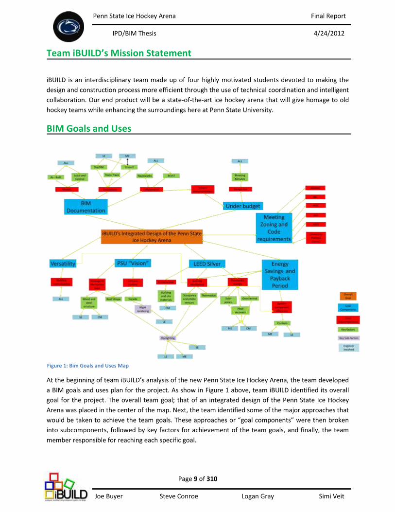
At the beginning of team iBUILD’s analysis of the new Penn State Ice Hockey Arena, the team developed
a BIM goals and uses plan for the project. As show in Figure 1 above, team iBUILD identified its overall
goal for the project. The overall team goal; that of an integrated design of the Penn State Ice Hockey
Arena was placed in the center of the map. Next, the team identified some of the major approaches that
would be taken to achieve the team goals. These approaches or “goal components” were then broken
into subcomponents, followed by key factors for achievement of the team goals, and finally, the team
member responsible for reaching each specific goal.
Figure 1: Bim Goals and Uses Map
Penn State Ice Hockey Arena Final Report
IPD/BIM Thesis 4/24/2012
Page 10 of 310 Joe Buyer Steve Conroe Logan Gray Simi Veit
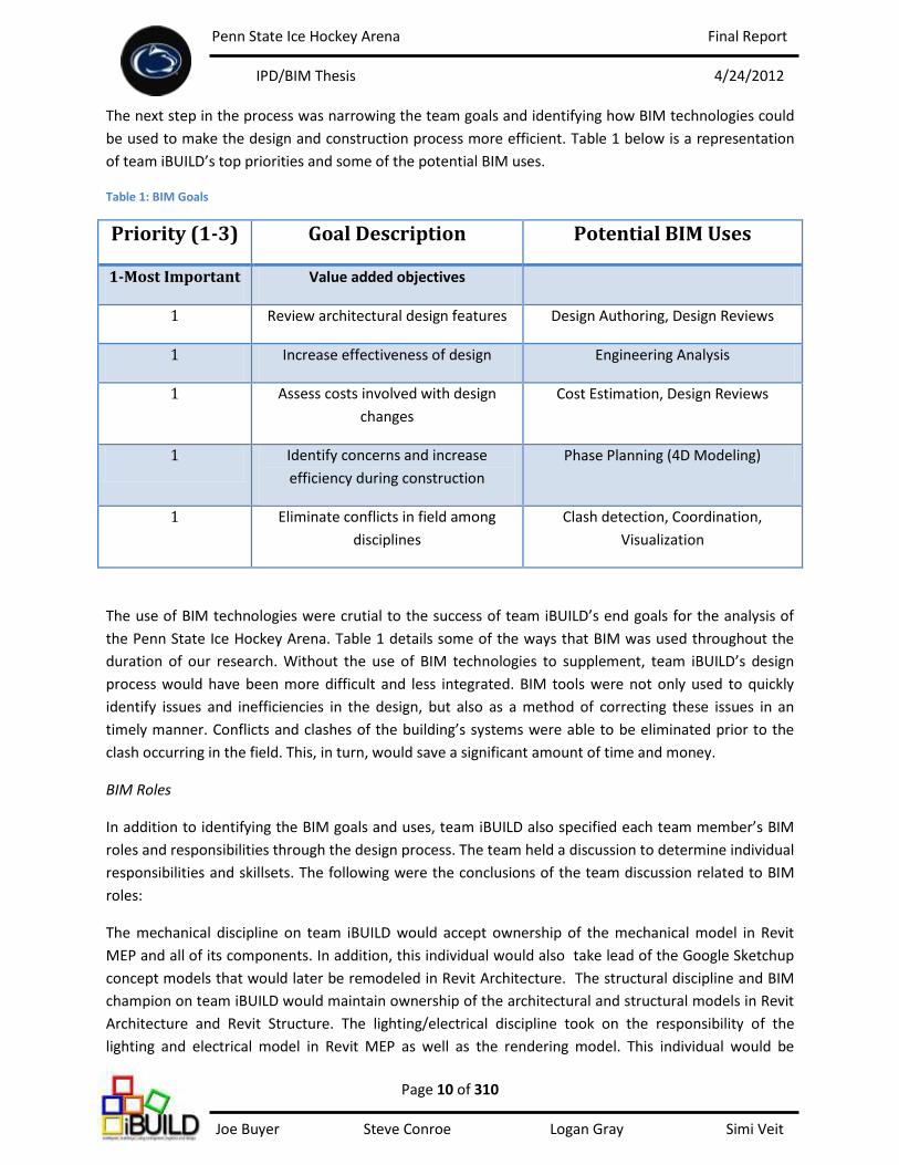
The next step in the process was narrowing the team goals and identifying how BIM technologies could
be used to make the design and construction process more efficient. Table 1 below is a representation
of team iBUILD’s top priorities and some of the potential BIM uses.
Table 1: BIM Goals
Priority (1-3) Goal Description Potential BIM Uses
1-Most Important Value added objectives
1 Review architectural design features Design Authoring, Design Reviews
1 Increase effectiveness of design Engineering Analysis
1 Assess costs involved with design
changes
Cost Estimation, Design Reviews
1 Identify concerns and increase
efficiency during construction
Phase Planning (4D Modeling)
1 Eliminate conflicts in field among
disciplines
Clash detection, Coordination,
Visualization
The use of BIM technologies were crutial to the success of team iBUILD’s end goals for the analysis of
the Penn State Ice Hockey Arena. Table 1 details some of the ways that BIM was used throughout the
duration of our research. Without the use of BIM technologies to supplement, team iBUILD’s design
process would have been more difficult and less integrated. BIM tools were not only used to quickly
identify issues and inefficiencies in the design, but also as a method of correcting these issues in an
timely manner. Conflicts and clashes of the building’s systems were able to be eliminated prior to the
clash occurring in the field. This, in turn, would save a significant amount of time and money.
BIM Roles
In addition to identifying the BIM goals and uses, team iBUILD also specified each team member’s BIM
roles and responsibilities through the design process. The team held a discussion to determine individual
responsibilities and skillsets. The following were the conclusions of the team discussion related to BIM
roles:
The mechanical discipline on team iBUILD would accept ownership of the mechanical model in Revit
MEP and all of its components. In addition, this individual would also take lead of the Google Sketchup
concept models that would later be remodeled in Revit Architecture. The structural discipline and BIM
champion on team iBUILD would maintain ownership of the architectural and structural models in Revit
Architecture and Revit Structure. The lighting/electrical discipline took on the responsibility of the
lighting and electrical model in Revit MEP as well as the rendering model. This individual would be
Penn State Ice Hockey Arena Final Report
IPD/BIM Thesis 4/24/2012
Page 11 of 310 Joe Buyer Steve Conroe Logan Gray Simi Veit
responsible for exporting the linked Revit model into 3D Studio Max to perform renderings that would
be used for presentations. Finally, the construction management student took on the responsibility of
maintaining the coordination model. The linked Revit model would be exported to Autodesk Navisworks
to perform clash detection and 4D phase planning.
Integrated Project Delivery and Team Workflow
Integration and collaboration among the team members that comprised iBUILD was critical in achieving
the team’s goals for the project. Through the combination of an integrated team and the incorporation
of BIM technologies into the design and construction process, team iBUILD was able to operate in an
extremely efficient manner and deliver the best product to the end user.
Team iBUILD was comprised of a student in each of the architectural engineering disciplines, including:
structural, mechanical, lighting/electrical, and construction management. In order to perform well as a
team and achieve team goals, constant communication and collaboration was required. The team
discovered a number of ways to communicate throughout the duration of our research, including: group
text messaging through the application “GroupMe”, email and daily meetings that involved two or more
team members. Brainstorming sessions were incorporated into team meetings to develop design
concepts and identify/resolve project concerns.
In terms of workflow, team iBUILD created a schedule of tasks to be performed up unitl the completion
of the project. After multiple iterations as a result of team and faculty discussions, the schedule of tasks
was broken into the three sections. The three sections of the schedule represented each of the three
team analyses to be performed. Team iBUILD’s areas of analysis for the Penn State Ice Hockey Arena
were the main arena, the eastern façade and the community ice rink.
Team iBUILD was able to create a schedule of each individual’s analyses by determining the effects of
one individual’s tasks on another. The team had to identify which tasks had to be completed for other
tasks to begin. A logical approach was necessary in developing and scheduling tasks for each individual
team member. Refer to Appendix Y for the final revision of team iBUILD’s schedule.
The following work performed by team iBUILD was made possible the establishment of a team
workflow. A significant amount of time involving careful planning was necessary for the smooth
operation of the team. After individual tasks and team goals were strategically planned, the members of
team iBUILD were able to begin work on the three analyses. Maintaining individual progress was critical
to the success of the team as a whole. If one task were to fall behind, it was likely that another
individual’s work would be effected. Team iBUILD worked diligently to maintain the project schedule
and allowed for a successful end product.

Penn State Ice Hockey Arena Final Report
IPD/BIM Thesis 4/24/2012
Page 12 of 310 Joe Buyer Steve Conroe Logan Gray Simi Veit
Main Arena Executive Summary After an initial review of Penn State’s feasibility study for the ice hockey arena team iBUILD
chose focus design efforts for the main arena around four central concepts: 1. Provide a unique space
that pays tribute to the traditional hockey barn, 2. Deliver championship ice, 3. Meeting all NCAA
Division 1 requirements; all while 4. Providing an integrated solution that truly reflects the integrated
project delivery method approach used to deliver the project. However, there were some challenges
that needed to be overcome in order for team iBUILD to reach all goals outlined for the main arena.
By providing a unique space a unique structural roof system was used as an architectural feature
and the central means for hiding systems that are typically left exposed in an ice hockey arena. To have
championship ice the temperature of the ice must be kept very cold (20 degrees Fahrenheit), and to
have cold ice the temperature of the arena must be kept cold as well (58 degrees Fahrenheit). The
typical building is designed to have temperatures well above the 58 degree set temperature; therefore
the seating bowl was designed to provide localized comfort for the patrons who will be watching from
the seats within the stadium. To be able to consider an ice hockey arena division 1 caliber there are
certain light levels that must be met on the ice. Penn State specifically stated that there is NCAA and
broadcasting light levels that team iBUILD insisted on providing. Bringing all of team iBUILD’s goals
together came to fruition with the use of an integrated design feature in the main arena. This design
feature is the truss that looks similar to the bottom of a skate blade. Also, the truss would span the
width of the arena and has been designed to encompass all mechanical, electrical, and plumbing main
lines. Figures 2, 3, and 4 below show finished renderings of the main arena.
Figure 3. A view of the main arena from the student section.
Figure 2. A view of the main arena from a club box.
Figure 4. A view of the main arena from the east lobby entrance.
Penn State Ice Hockey Arena Final Report
IPD/BIM Thesis 4/24/2012
Page 13 of 310 Joe Buyer Steve Conroe Logan Gray Simi Veit
Structural Solution Executive Summary As outlined in the design intent, the truss will be a very integral and integrated feature in the main
arena. It is designed to house mechanical ductwork, electrical conduit, and plumbing mains; all while acting
as the main structural support for the roof system. This in itself shows how big of a factor collaboration was
throughout the design process for team iBUILD. Using integration concurrently with emerging BIM
technologies there were constant checks being done to ensure that no interferences occurred between all
team models. The structural engineering student performed structural modeling in SAP 2000 and attempted
to import modeled geometries and sections into Revit but was unsuccessful; probably because such complex
geometries were modeled. As a personal goal the structural engineering student aimed to utilize as much
BIM technology that is currently available to help fulfill the tasks laid out in team iBUILD’s proposal.
The structural contribution to the design of the main arena focused on the design of the main truss
and the frame that resists the resultant thrusts from the pin ended arched truss. As requested by faculty
advisors, the structural student carried out two design alternatives for the curved truss over the main arena.
The first design option for structural portion of the truss will feature two steel wide flange shapes acting as
the top chords, a wooden glued-laminated member acting as the web member and shear transfer
mechanism, and a steel bottom chord that will close the V-shaped truss. The second option, which will have
the same overall shape, will be designed using structural steel for every element of the truss and is designed
to be encased in a thin, glue laminate wood paneling. The two options were carried out allowing team
iBUILD to compare constructability, maintenance, and cost for the two systems.
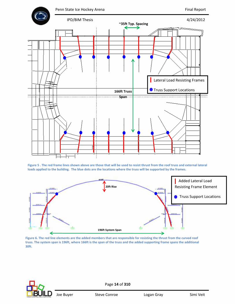
The truss and supporting frames span 196 feet in the north and south directions over the main ice
sheet. The truss will have a curved shape with a rise of 20ft to the peak, providing a 74ft clearance over the
ice sheet. In a collaborative effort with input from the other design disciplines the structural student carried
out multiple design iterations achieving a safe and economical structural solution. The geometries used can
be seen in figures 5 and 6 on the following page.
To decrease member sizes in the curved truss over the main arena, thrust resisting elements were
incorporated into the existing gravity load and lateral load resisting frames of the main arena. This required
the gravity and lateral frames at these framing lines to be designed to resist this added thrusting/lateral
force. Without inducing a thrust into the arched truss the member sizes become extremely uneconomical
and could only be downsized when the frames were designed to resist the thrust from the arch.
Penn State Ice Hockey Arena Final Report
IPD/BIM Thesis 4/24/2012
Page 14 of 310 Joe Buyer Steve Conroe Logan Gray Simi Veit
20ft Rise
Figure 5 . The red frame lines shown above are those that will be used to resist thrust from the roof truss and external lateral loads applied to the building. The blue dots are the locations where the truss will be supported by the frames.
166ft Truss
Span
196ft System Span
Lateral Load Resisting Frames
Truss Support Locations
~35ft Typ. Spacing
Added Lateral Load
Resisting Frame Element
Truss Support Locations
196ft System Span
Figure 6. The red line elements are the added members that are responsible for resisting the thrust from the curved roof truss. The system span is 196ft, where 166ft is the span of the truss and the added supporting frame spans the additional 30ft.
Penn State Ice Hockey Arena Final Report
IPD/BIM Thesis 4/24/2012
Page 15 of 310 Joe Buyer Steve Conroe Logan Gray Simi Veit
Using glued-laminated timber as the web member in one design option and as an exterior
architectural panel in the second design option allowed team iBUILD to explore the option of using
locally harvested hardwoods as a structural and architectural feature in the main arena. Working
closely with the construction management (CM) student, the structural discipline used design values
based on the hardwood tree types being used in the fabrication process of the glued-laminated
members. Having the CM in design reviews throughout the process of the design allowed for constant
cost comparisons to be carried out and allowed the structural engineer to further develop the design
that was found to be more cost effective. Using the CM’s input all erection, scheduling, and fabrication
considerations were taken into account while the design process advanced. This includes: specifying
enough splice locations to facilitate the desired erection process, simplifying the manufacturing process,
and limiting the crane size needed on the job site. The structural discipline aided the CM’s plan to
perform a crane analysis for the trusses used in the main arena. Calculations were carried out to verify
and size of the crane needed to perform the erection process of the integrated truss.
This system will also require constant interaction with the mechanical engineering (ME) student
throughout the process of the design. An example of this is: the higher the peak of the roof becomes
the larger the volume of space within the main arena, which directly affects the demand load for the
ME’s mechanical systems. The size of ducts, which are to be housed within the truss frame, will also be
a major factor for sizing the truss because enough space must be left within the truss to allow for the
mechanical system to fit. There has also been a concern as to how to access mechanical equipment if a
problem arises and service needs to be done on the equipment within. Team iBUILD designed the truss
to have hidden access panels at strategic places in the span of the composite truss and designed the
truss with panels to hinge which allows for the equipment to be serviced if a problem does occur. With
the use of design review meetings and clash detection sessions between all parties, an optimum
solution was formulated for the structural system, but more importantly, for the University who will
benefit most as owner.
Penn State Ice Hockey Arena Final Report
IPD/BIM Thesis 4/24/2012
Page 16 of 310 Joe Buyer Steve Conroe Logan Gray Simi Veit
Main Arena Design Approach
In order to provide an aesthetically pleasing modern and clean look for the main arena an
integrated design approach was carried out. The central idea was to design a structural system that
houses all mechanical, electrical, and plumbing main lines within its core. The idea for housing all
systems was based on a design used in the Richmond Olympic Oval, which is located in British Columbia.
Once this initial architectural idea was formulated, team iBUILD worked collaboratively to design an
integrated system that will house all design disciplines’ main systems while keeping them hidden from
sight from the people within the arenas. The profile of the integrated roof truss will be that of the
bottom of a skate blade, which will give tribute to the main use of the arena, ice hockey. The ultimate
goal is to produce a roof that is very clean when looking at it from the inside of the main seating bowl;
all while housing the necessary MEP systems to make the main arena a division 1 hockey destination.
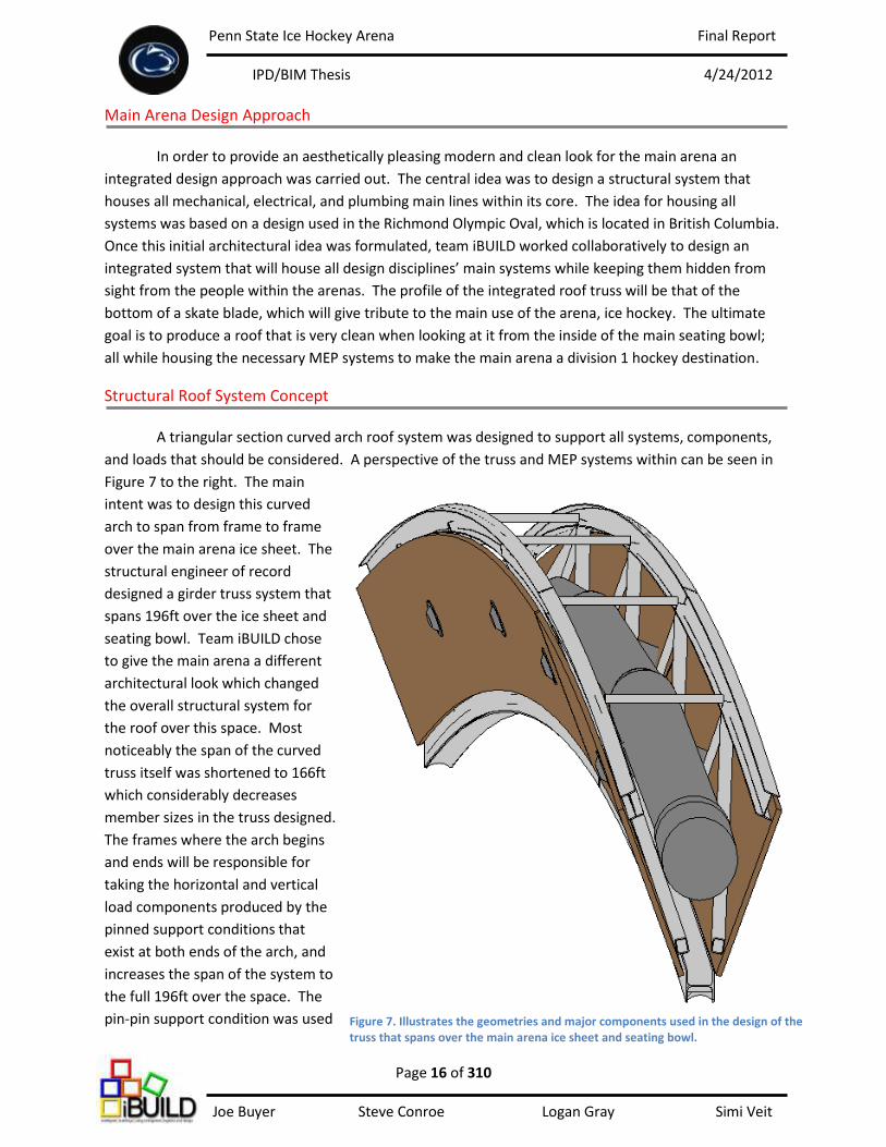
Structural Roof System Concept A triangular section curved arch roof system was designed to support all systems, components,
and loads that should be considered. A perspective of the truss and MEP systems within can be seen in
Figure 7 to the right. The main
intent was to design this curved
arch to span from frame to frame
over the main arena ice sheet. The
structural engineer of record
designed a girder truss system that
spans 196ft over the ice sheet and
seating bowl. Team iBUILD chose
to give the main arena a different
architectural look which changed
the overall structural system for
the roof over this space. Most
noticeably the span of the curved
truss itself was shortened to 166ft
which considerably decreases
member sizes in the truss designed.
The frames where the arch begins
and ends will be responsible for
taking the horizontal and vertical
load components produced by the
pinned support conditions that
exist at both ends of the arch, and
increases the span of the system to
the full 196ft over the space. The
pin-pin support condition was used Figure 7. Illustrates the geometries and major components used in the design of the truss that spans over the main arena ice sheet and seating bowl.
Penn State Ice Hockey Arena Final Report
IPD/BIM Thesis 4/24/2012
Page 17 of 310 Joe Buyer Steve Conroe Logan Gray Simi Veit
[schoolyardpuck.com, 2010]
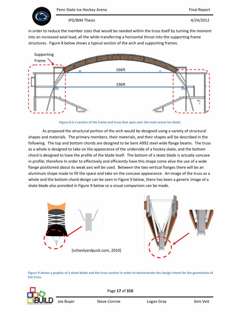
in order to reduce the member sizes that would be needed within the truss itself by turning the moment
into an increased axial load; all the while transferring a horizontal thrust into the supporting frame
structures. Figure 8 below shows a typical section of the arch and supporting frames.
Figure 8 is a section of the frame and truss that span over the main arena ice sheet.
As proposed the structural portion of the arch would be designed using a variety of structural
shapes and materials. The primary members, their materials, and their shapes will be described in the
following. The top and bottom chords are designed to be bent A992 steel wide flange beams. The truss
as a whole is designed to take on the appearance of the underside of a hockey skate, and the bottom
chord is designed to have the profile of the blade itself. The bottom of a skate blade is actually concave
in profile; therefore In order to effectively and efficiently have this shape come alive the use of a wide
flange positioned about its weak axis will be used. Between the two vertical flanges there will be an
aluminum shape made to fill the space and take on the concave appearance. An image of the truss as a
whole and the bottom chord design can be seen in Figure 9 below, there has been a generic image of a
skate blade also provided in Figure 9 below so a visual comparison can be made.
166ft
196ft
Supporting
Frame
Figure 9 shows a graphic of a skate blade and the truss section in order to demonstrate the design intent for the geometries of the truss.

Penn State Ice Hockey Arena Final Report
IPD/BIM Thesis 4/24/2012
Page 18 of 310 Joe Buyer Steve Conroe Logan Gray Simi Veit
Structural Roof Components
The first part of the roof design is the long span metal deck. This product is manufactured to do
exactly what its name implies, which is span large lengths. Maximum snow, wind, and dead loads were
considered in the selection of the product and the proposed solution is spans from beam to beam in the
roof system. At the ends of each deck span, every 20 feet, there will be glued-laminated beams where
the deck will bear and be supported. The intermediary beams will also act as lateral bracing for the top
chords along the length of the span. These intermediate supports will span between the main
supporting structures (the curved arches) and will be made of Pennsylvania hardwoods that Rigidply
Manufacturers, our contact for cost analysis information, claims to be able to manufacture. The
purpose of using Pennsylvania hardwoods was to take advantage of a regional material and to explore
the possibility of using a product that is not used very often but can be found readily in Pennsylvania.
The use of these hardwoods was then explored as the web members in the curved truss that support
the entirety of the main arena roof system. This leads to one of the more complex aspects of the
structural system that will support the main arena, the integrated truss.
Structural Student and an Integrated Approach
In designing the truss, input from each member of the design team was considered. Fabrication
and erection sequencing was a major concern for both the
structural and construction management student. There was
thought of reducing the depth of the truss at the center of the span
and also thought of reducing the cross section of steel toward the
support locations; this could have been done but proved more of a
fabrication problem than worth. The amount of supplies that
would have been saved would not have outweighed the complexity
that would have been added to the cost in fabrication; actual cost
comparisons can be seen in the construction management section
for the main arena. Team iBUILD also proposed doing a cost
comparison using two different materials as web members;
therefore a common geometry was kept constant throughout the
design of both options. The geometries that were held constant
can be seen in Figure 10 to the right. There was also a considerable
amount of time spent analyzing the erection sequencing procedure
for the truss; and this will be discussed in greater detail later. In
working with the lighting/electrical student it became apparent
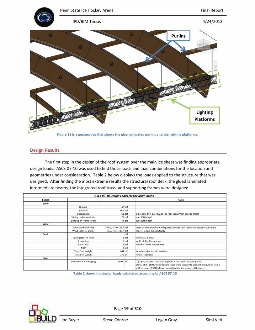
that supports were needed for lighting platforms. The structural glued-laminated beams spanning
between the trusses in the roof system were located in places where the lighting stages could most
effectively light the ice. Figure 11 below shows the glued-laminated beams and the lighting platforms.
84in
34in 34in
Figure 10 shows geometries held constant for the two alternative truss designs.
Penn State Ice Hockey Arena Final Report
IPD/BIM Thesis 4/24/2012
Page 19 of 310 Joe Buyer Steve Conroe Logan Gray Simi Veit
Loads Notes
Snow
Ground 40 psf
Balanced 33.9 psf
Unbalanced 61 psf max snow drift over 1/2 of the roof span (from eave to crest)
Sliding on Frame Roofs 75 psf over 15ft length
Drifting on Frame Roofs 73 psf over 15ft length
Wind
Wind Load (MWFRs) -40.0, -37.0, -25.6 psf these values are windward quarter, center half, leeward quarter respectively
Wind Loads (C and C) -35.6, -51.1, -80.7 psf Zone 1, 2, and 3 respectively
Dead psf
Corrugated Tin Roof 1 psf from AISC manual
Insulation 6 psf for 6" of Rigid Insulation
Roof Deck 8 psf from EPIC Deck spec sheets
MEP 3 psf
Truss Self Weight 464 plf for composite wood-steel truss
Truss Self Weight 276 plf for all-steel truss
Live
Scoreboard and Rigging 15000 lb (1 ) 15,000lb point load was applied at the center of each perlin
a total of (6) 15000lb socreboard loads were taken into account and turned into a
uniform load of 522lb/ft and considered in the design of the truss
ASCE 07-10 Design Loads for the Main Arena
Figure 11 is a perspective that shows the glue laminated purlins and the lighting platforms.
Design Results The first step in the design of the roof system over the main ice sheet was finding appropriate
design loads. ASCE 07-10 was used to find those loads and load combinations for the location and
geometries under consideration. Table 2 below displays the loads applied to the structure that was
designed. After finding the most extreme results the structural roof deck, the glued laminated
intermediate beams, the integrated roof truss, and supporting frames were designed.
[Type a quote from the document or
the summary of an interesting point.
You can position the text box
anywhere in the document. Use the
Drawing Tools tab to change the
formatting of the pull quote text box.]
[Type a quote from the document or
the summary of an interesting point.
You can position the text box
anywhere in the document. Use the
Drawing Tools tab to change the
formatting of the pull quote text box.]
Purlins
Lighting
Platforms
Table 2 shows the design loads calculated according to ASCE 07-10

Penn State Ice Hockey Arena Final Report
IPD/BIM Thesis 4/24/2012
Page 20 of 310 Joe Buyer Steve Conroe Logan Gray Simi Veit
Roof Deck:
As mentioned previously, the roof deck chosen is a long span deck system, manufactured by
Epic Metals. Epic Metals produces a wide variety of decking systems that are designed to span long
lengths while enhancing the architecture and acoustics of the space below. After finding the worst case
snow drift and wind loads the Archdeck PA Deck
System, which is capable of being bent in its strong
direction, was chosen. An image of the long span
deck can be seen in Figure 12 to the left. A copy of
the long span deck specification and technical
tables is located in Appendix B. The specified
rise/span ratio used is 20/166 or 0.12, therefore
based on manufacturer specifications the
maximum allowable service load for a 16 gage
steel system spanning 20ft is 83psf which is below
the maximum load of 71psf found for the service load combinations used in the main arena roof system.
[products.construction.com, 2012]
16 gage Rise/Span Ratio = 0.12
Figure 12 is a graphic showing the profile of Epic Metals Archdeck system and relevant properties.
Penn State Ice Hockey Arena Final Report
IPD/BIM Thesis 4/24/2012
Page 21 of 310 Joe Buyer Steve Conroe Logan Gray Simi Veit
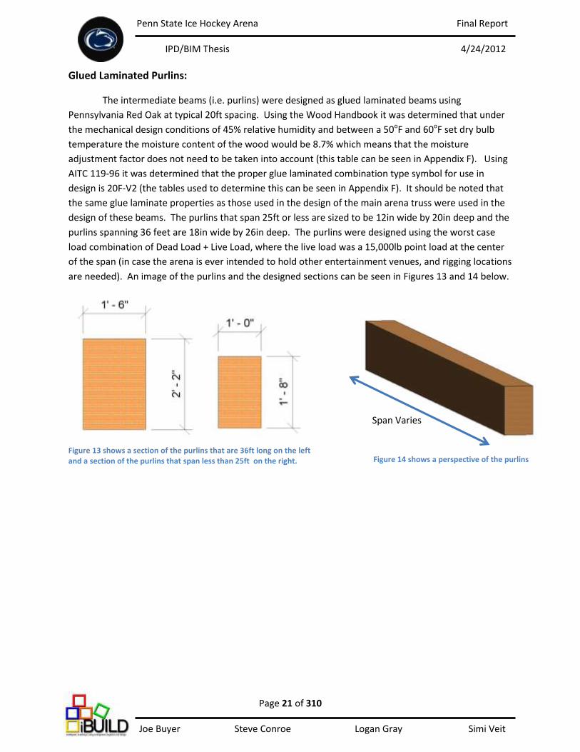
Glued Laminated Purlins:
The intermediate beams (i.e. purlins) were designed as glued laminated beams using
Pennsylvania Red Oak at typical 20ft spacing. Using the Wood Handbook it was determined that under
the mechanical design conditions of 45% relative humidity and between a 50oF and 60oF set dry bulb
temperature the moisture content of the wood would be 8.7% which means that the moisture
adjustment factor does not need to be taken into account (this table can be seen in Appendix F). Using
AITC 119-96 it was determined that the proper glue laminated combination type symbol for use in
design is 20F-V2 (the tables used to determine this can be seen in Appendix F). It should be noted that
the same glue laminate properties as those used in the design of the main arena truss were used in the
design of these beams. The purlins that span 25ft or less are sized to be 12in wide by 20in deep and the
purlins spanning 36 feet are 18in wide by 26in deep. The purlins were designed using the worst case
load combination of Dead Load + Live Load, where the live load was a 15,000lb point load at the center
of the span (in case the arena is ever intended to hold other entertainment venues, and rigging locations
are needed). An image of the purlins and the designed sections can be seen in Figures 13 and 14 below.
Span Varies
Figure 13 shows a section of the purlins that are 36ft long on the left and a section of the purlins that span less than 25ft on the right. Figure 14 shows a perspective of the purlins
Penn State Ice Hockey Arena Final Report
IPD/BIM Thesis 4/24/2012
Page 22 of 310 Joe Buyer Steve Conroe Logan Gray Simi Veit
34in 34in
84in
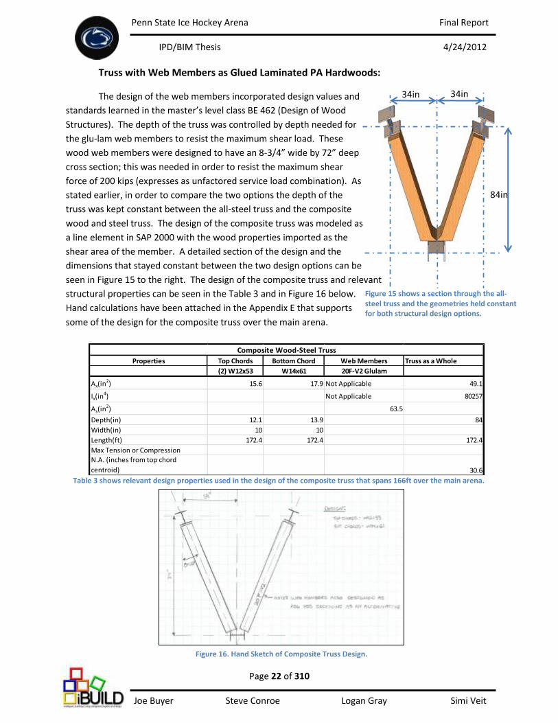
Properties Top Chords Bottom Chord Web Members Truss as a Whole
(2) W12x53 W14x61 20F-V2 Glulam
Ax(in2) 15.6 17.9 Not Applicable 49.1
Ix(in4) Not Applicable 80257
As(in2) 63.5
Depth(in) 12.1 13.9 84
Width(in) 10 10
Length(ft) 172.4 172.4 172.4
Max Tension or Compression
N.A. (inches from top chord
centroid) 30.6
Composite Wood-Steel Truss
Truss with Web Members as Glued Laminated PA Hardwoods:
The design of the web members incorporated design values and
standards learned in the master’s level class BE 462 (Design of Wood
Structures). The depth of the truss was controlled by depth needed for
the glu-lam web members to resist the maximum shear load. These
wood web members were designed to have an 8-3/4” wide by 72” deep
cross section; this was needed in order to resist the maximum shear
force of 200 kips (expresses as unfactored service load combination). As
stated earlier, in order to compare the two options the depth of the
truss was kept constant between the all-steel truss and the composite
wood and steel truss. The design of the composite truss was modeled as
a line element in SAP 2000 with the wood properties imported as the
shear area of the member. A detailed section of the design and the
dimensions that stayed constant between the two design options can be
seen in Figure 15 to the right. The design of the composite truss and relevant
structural properties can be seen in the Table 3 and in Figure 16 below.
Hand calculations have been attached in the Appendix E that supports
some of the design for the composite truss over the main arena.
Figure 15 shows a section through the all-steel truss and the geometries held constant for both structural design options.
Table 3 shows relevant design properties used in the design of the composite truss that spans 166ft over the main arena.
Figure 16. Hand Sketch of Composite Truss Design.
Penn State Ice Hockey Arena Final Report
IPD/BIM Thesis 4/24/2012
Page 23 of 310 Joe Buyer Steve Conroe Logan Gray Simi Veit
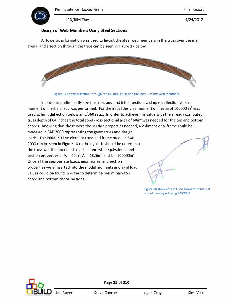
Design of Web Members Using Steel Sections
A Howe truss formation was used to layout the steel web members in the truss over the main
arena, and a section through the truss can be seen in Figure 17 below.
Figure 17 shows a section through the all-steel truss and the layout of the web members.
In order to preliminarily size the truss and find initial sections a simple deflection versus
moment of inertia check was performed. For the initial design a moment of inertia of 100000 in4 was
used to limit deflection below an L/360 ratio. In order to achieve this value with the already computed
truss depth of 84 inches the total steel cross sectional area of 60in2 was needed for the top and bottom
chords. Knowing that these were the section properties needed, a 2 dimensional frame could be
modeled in SAP 2000 representing the geometries and design
loads. The initial 2D line element truss and frame made in SAP
2000 can be seen in Figure 18 to the right. It should be noted that
the truss was first modeled as a line item with equivalent steel
section properties of Ax = 60in2, As = 68.5in2, and Ix = 100000in4.
Once all the appropriate loads, geometries, and section
properties were inserted into the model moments and axial load
values could be found in order to determine preliminary top
chord and bottom chord sections.
Figure 18 shows the 2D line element structural model developed using SAP2000.
Penn State Ice Hockey Arena Final Report
IPD/BIM Thesis 4/24/2012
Page 24 of 310 Joe Buyer Steve Conroe Logan Gray Simi Veit
Joint Number Joint location Load Combination
Actual Deflection
(in) L/360 (in) Limit L/240 (in) Limit
92 Center of Span, Bottom Chord D+S+L 6.97 5.53 8.30
110 Center of Span, Top Chord D+S+L 6.96 5.53 8.30
92 Center of Span, Bottom Chord D+.75S+.75L 6.00 5.53 8.30
Maximum Deflections in Truss
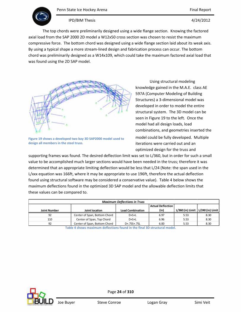
The top chords were preliminarily designed using a wide flange section. Knowing the factored
axial load from the SAP 2000 2D model a W12x50 cross section was chosen to resist the maximum
compressive force. The bottom chord was designed using a wide flange section laid about its weak axis.
By using a typical shape a more stream-lined design and fabrication process can occur. The bottom
chord was preliminarily designed as a W14x109, which could take the maximum factored axial load that
was found using the 2D SAP model.
Using structural modeling
knowledge gained in the M.A.E. class AE
597A (Computer Modeling of Building
Structures) a 3-dimensional model was
developed in order to model the entire
structural system. The 3D model can be
seen in Figure 19 to the left. Once the
model had all design loads, load
combinations, and geometries inserted the
model could be fully developed. Multiple
iterations were carried out and an
optimized design for the truss and
supporting frames was found. The desired deflection limit was set to L/360, but in order for such a small
value to be accomplished much larger sections would have been needed in the truss; therefore it was
determined that an appropriate limiting deflection would be less that L/24 (Note: the span used in the
L/xxx equation was 166ft, where it may be appropriate to use 196ft, therefore the actual deflection
found using structural software may be considered a conservative value). Table 4 below shows the
maximum deflections found in the optimized 3D SAP model and the allowable deflection limits that
these values can be compared to.
Table 4 shows maximum deflections found in the final 3D structural model.
Figure 19 shows a developed two bay 3D SAP2000 model used to design all members in the steel truss.

Penn State Ice Hockey Arena Final Report
IPD/BIM Thesis 4/24/2012
Page 25 of 310 Joe Buyer Steve Conroe Logan Gray Simi Veit
Design Results for Steel Truss:
The top chords in the truss are designed as bent W12x53 members. The bottom chord in the
truss is designed to be W14x61 members laid about its weak axis. The top and bottom chords were
designed with internal web members that would brace them at every 20ft. The final design and
geometries used in the design can be seen in Figure 20 below. The following forces, expressed as
maximum factored loads in the top and bottom chords for a typical configuration, were found using the
3D structural model:
Top Chord Maximum Compressive Load, C= 321 kips
Top Chord Maximum Tensile Load, T= 138 kips
Bottom Chord Maximum Compressive Load, C= 370 kips
Bottom Chord Maximum Tensile Load, T= 364 kips
34in 34in
84in
Web Members as
Specified
W12x53
Top
Chords
W14x61
Bottom
Chord
Figure 20 shows the design sections used as the top and bottom chords and the geometries used for both design alternatives of the truss
Penn State Ice Hockey Arena Final Report
IPD/BIM Thesis 4/24/2012
Page 26 of 310 Joe Buyer Steve Conroe Logan Gray Simi Veit
Properties Top Chords Bottom Chord Truss as a Whole
(2) W12x53 W14x61 (4) HSS 6x6x5/16 (4) HSS 6x6x5/16 (4) HSS 6x6x3/8 (4) HSS 6x6x5/8 (4) HSS 8x8x5/16
Ax(in2) 15.6 17.9 Not Applicable Not Applicable Not Applicable Not Applicable Not Applicable 49.1
Ix(in4) Not Considered Not Considered Not Applicable Not Applicable Not Applicable Not Applicable Not Applicable 80257
As(in2) Not Considered Not Considered
Depth(in) 12.1 13.9 84
Width(in) 10 10
Length(ft) 172.4 172.4 172.4
Maximum UBL (ft) 20 20 18.3 18.9 19.6 20.3 21.1
Max Compression (K) *Found Using
1.2D+1.6S+1.0L 321 370 31 86 131 166 191
Max Tension (K) *Found Using
1.2D+1.6S+1.0L 138 364
Nuetral Axis Location (inches
from top chord centroid) 30.6
Web Members
Steel Truss
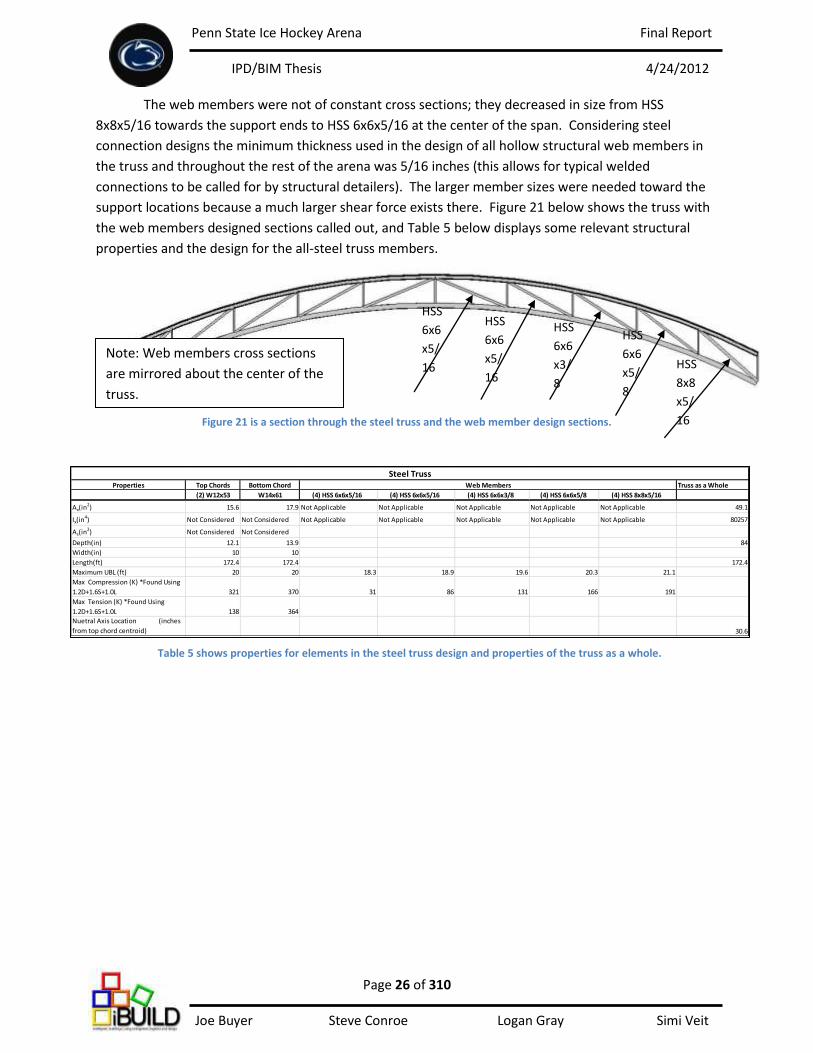
The web members were not of constant cross sections; they decreased in size from HSS
8x8x5/16 towards the support ends to HSS 6x6x5/16 at the center of the span. Considering steel
connection designs the minimum thickness used in the design of all hollow structural web members in
the truss and throughout the rest of the arena was 5/16 inches (this allows for typical welded
connections to be called for by structural detailers). The larger member sizes were needed toward the
support locations because a much larger shear force exists there. Figure 21 below shows the truss with
the web members designed sections called out, and Table 5 below displays some relevant structural
properties and the design for the all-steel truss members.
Figure 21 is a section through the steel truss and the web member design sections.
HSS
6x6
x5/
16
HSS
6x6
x5/
16
HSS
6x6
x3/
8
HSS
6x6
x5/
8
HSS
8x8
x5/
16
Note: Web members cross sections
are mirrored about the center of the
truss.
Table 5 shows properties for elements in the steel truss design and properties of the truss as a whole.
Penn State Ice Hockey Arena Final Report
IPD/BIM Thesis 4/24/2012
Page 27 of 310 Joe Buyer Steve Conroe Logan Gray Simi Veit
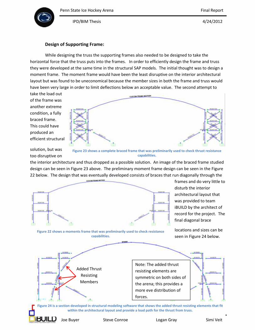
Design of Supporting Frame:
While designing the truss the supporting frames also needed to be designed to take the
horizontal force that the truss puts into the frames. In order to efficiently design the frame and truss
they were developed at the same time in the structural SAP models. The initial thought was to design a
moment frame. The moment frame would have been the least disruptive on the interior architectural
layout but was found to be uneconomical because the member sizes in both the frame and truss would
have been very large in order to limit deflections below an acceptable value. The second attempt to
take the load out
of the frame was
another extreme
condition, a fully
braced frame.
This could have
produced an
efficient structural
solution, but was
too disruptive on
the interior architecture and thus dropped as a possible solution. An image of the braced frame studied
design can be seen in Figure 23 above. The preliminary moment frame design can be seen in the Figure
22 below. The design that was eventually developed consists of braces that run diagonally through the
frames and do very little to
disturb the interior
architectural layout that
was provided to team
iBUILD by the architect of
record for the project. The
final diagonal brace
locations and sizes can be
seen in Figure 24 below.
Figure 23 shows a complete braced frame that was preliminarily used to check thrust resistance capabilities.
Figure 22 shows a moments frame that was preliminarily used to check resistance capabilities.
Figure 24 is a section developed in structural modeling software that shows the added thrust resisting elements that fit within the architectural layout and provide a load path for the thrust from truss.
Note: The added thrust
resisting elements are
symmetric on both sides of
the arena; this provides a
more eve distribution of
forces.
Added Thrust
Resisting
Members
Penn State Ice Hockey Arena Final Report
IPD/BIM Thesis 4/24/2012
Page 28 of 310 Joe Buyer Steve Conroe Logan Gray Simi Veit
The braces were positioned to fit within interior walls on the event and main concourse levels that could
easily be framed around or left visible; this would be left to decide by the owner.
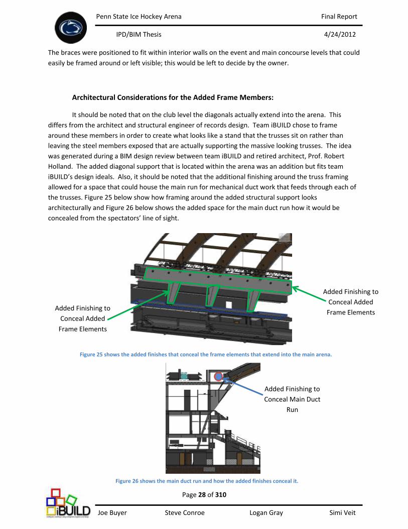
Architectural Considerations for the Added Frame Members:
It should be noted that on the club level the diagonals actually extend into the arena. This
differs from the architect and structural engineer of records design. Team iBUILD chose to frame
around these members in order to create what looks like a stand that the trusses sit on rather than
leaving the steel members exposed that are actually supporting the massive looking trusses. The idea
was generated during a BIM design review between team iBUILD and retired architect, Prof. Robert
Holland. The added diagonal support that is located within the arena was an addition but fits team
iBUILD’s design ideals. Also, it should be noted that the additional finishing around the truss framing
allowed for a space that could house the main run for mechanical duct work that feeds through each of
the trusses. Figure 25 below show how framing around the added structural support looks
architecturally and Figure 26 below shows the added space for the main duct run how it would be
concealed from the spectators’ line of sight.
Figure 25 shows the added finishes that conceal the frame elements that extend into the main arena.
Added Finishing to
Conceal Added
Frame Elements
Figure 26 shows the main duct run and how the added finishes conceal it.
Added Finishing to
Conceal Added
Frame Elements
Added Finishing to
Conceal Main Duct
Run
Penn State Ice Hockey Arena Final Report
IPD/BIM Thesis 4/24/2012
Page 29 of 310 Joe Buyer Steve Conroe Logan Gray Simi Veit
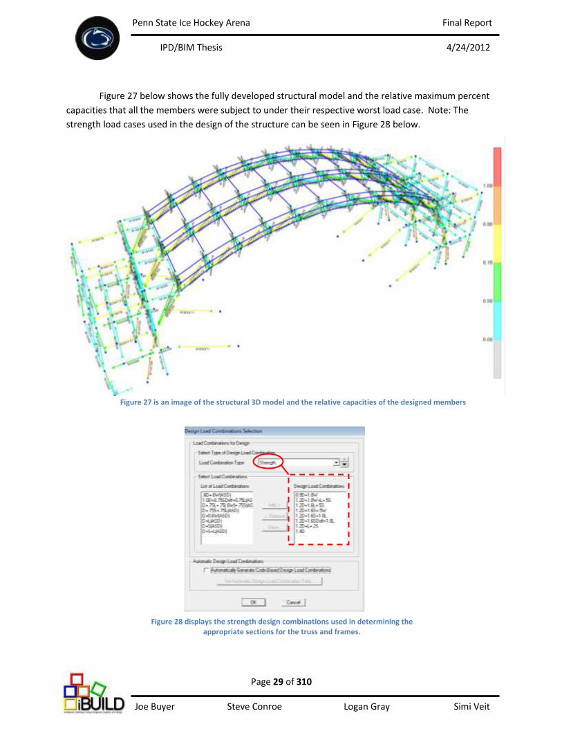
Figure 27 below shows the fully developed structural model and the relative maximum percent
capacities that all the members were subject to under their respective worst load case. Note: The
strength load cases used in the design of the structure can be seen in Figure 28 below.
Figure 27 is an image of the structural 3D model and the relative capacities of the designed members
Figure 28 displays the strength design combinations used in determining the appropriate sections for the truss and frames.
Penn State Ice Hockey Arena Final Report
IPD/BIM Thesis 4/24/2012
Page 30 of 310 Joe Buyer Steve Conroe Logan Gray Simi Veit
Truss Type Section Wood Weight (lbs) Wood Weight (tons) Steel Weight (lbs) Steel Weight (tons) Total Weight (lbs) Total Weight (tons)
Steel with Glulam Panels Ends 6051.24 3.03 8336.55 4.17 14387.79 7.19
Steel with Glulam Panels Middle 8068.32 4.03 11115.40 5.56 19183.72 9.59
Composite Glulam and Steel Ends 17649.45 8.82 6639.00 3.32 24288.45 12.14
Composite Glulam and Steel Middle 23532.60 11.77 8852.00 4.43 32384.60 16.19
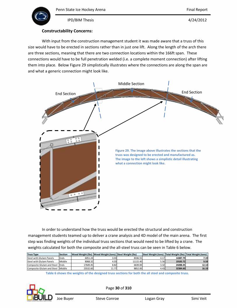
Constructability Concerns:
With input from the construction management student it was made aware that a truss of this
size would have to be erected in sections rather than in just one lift. Along the length of the arch there
are three sections, meaning that there are two connection locations within the 166ft span. These
connections would have to be full penetration welded (i.e. a complete moment connection) after lifting
them into place. Below Figure 29 simplistically illustrates where the connections are along the span are
and what a generic connection might look like.
In order to understand how the truss would be erected the structural and construction
management students teamed up to deliver a crane analysis and 4D model of the main arena. The first
step was finding weights of the individual truss sections that would need to be lifted by a crane. The
weights calculated for both the composite and the all-steel truss can be seen in Table 6 below.
Middle Section
End Section End Section
Figure 29. The image above illustrates the sections that the truss was designed to be erected and manufactured as. The image to the left shows a simplistic detail illustrating what a connection might look like.
Table 6 shows the weights of the designed truss sections for both the all steel and composite truss.
Penn State Ice Hockey Arena Final Report
IPD/BIM Thesis 4/24/2012
Page 31 of 310 Joe Buyer Steve Conroe Logan Gray Simi Veit
Team iBUILD eventually ruled out using PA hardwoods as the web member for the truss. This
large reduction in weight when using steel as web members and only have a hardwood paneling is one
of the many reasons for the choice. After finding that the center section weighs approximately 9.59
tons a crane analysis was performed and it was determined that a 100 ton crane would be necessary to
erect the all-steel truss where a 150 ton crane would be needed to erect the composite truss center
section that weighs approximately 16.19 tons.
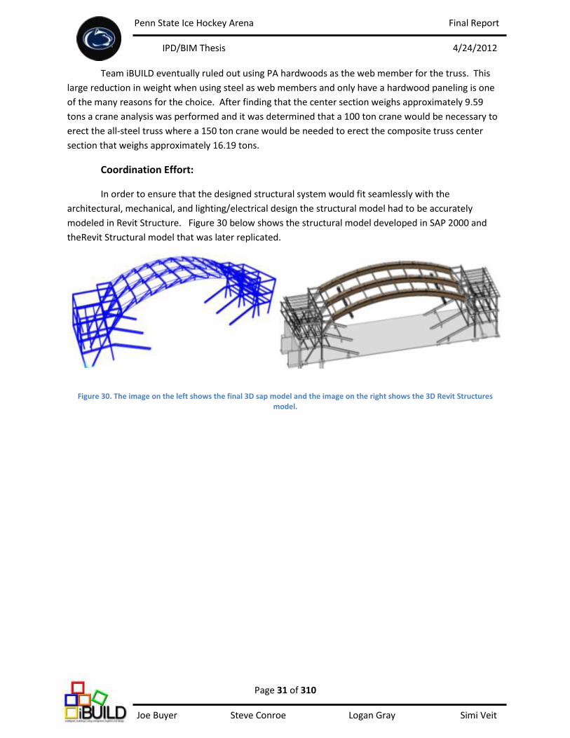
Coordination Effort:
In order to ensure that the designed structural system would fit seamlessly with the
architectural, mechanical, and lighting/electrical design the structural model had to be accurately
modeled in Revit Structure. Figure 30 below shows the structural model developed in SAP 2000 and
theRevit Structural model that was later replicated.
Figure 30. The image on the left shows the final 3D sap model and the image on the right shows the 3D Revit Structures model.
Penn State Ice Hockey Arena Final Report
IPD/BIM Thesis 4/24/2012
Page 32 of 310 Joe Buyer Steve Conroe Logan Gray Simi Veit
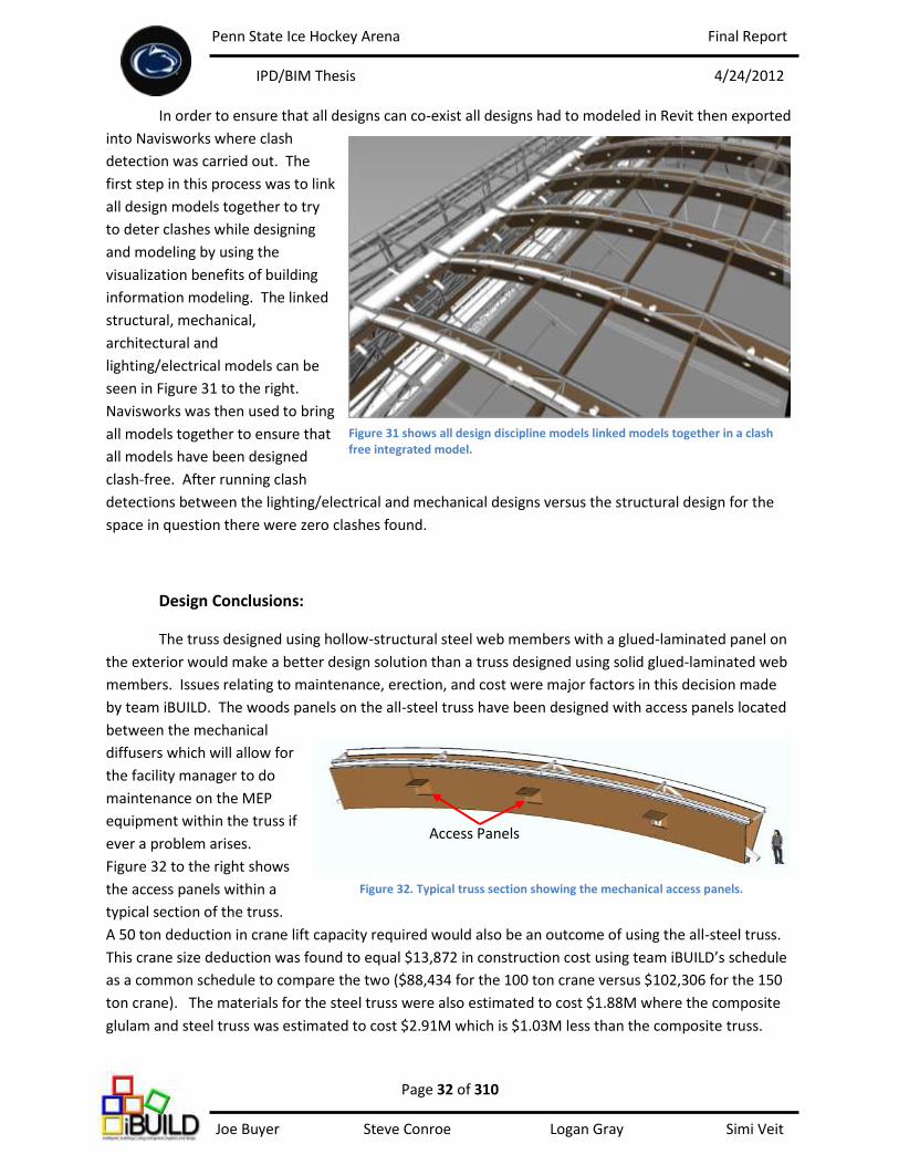
In order to ensure that all designs can co-exist all designs had to modeled in Revit then exported
into Navisworks where clash
detection was carried out. The
first step in this process was to link
all design models together to try
to deter clashes while designing
and modeling by using the
visualization benefits of building
information modeling. The linked
structural, mechanical,
architectural and
lighting/electrical models can be
seen in Figure 31 to the right.
Navisworks was then used to bring
all models together to ensure that
all models have been designed
clash-free. After running clash
detections between the lighting/electrical and mechanical designs versus the structural design for the
space in question there were zero clashes found.
Design Conclusions:
The truss designed using hollow-structural steel web members with a glued-laminated panel on
the exterior would make a better design solution than a truss designed using solid glued-laminated web
members. Issues relating to maintenance, erection, and cost were major factors in this decision made
by team iBUILD. The woods panels on the all-steel truss have been designed with access panels located
between the mechanical
diffusers which will allow for
the facility manager to do
maintenance on the MEP
equipment within the truss if
ever a problem arises.
Figure 32 to the right shows
the access panels within a
typical section of the truss.
A 50 ton deduction in crane lift capacity required would also be an outcome of using the all-steel truss.
This crane size deduction was found to equal $13,872 in construction cost using team iBUILD’s schedule
as a common schedule to compare the two ($88,434 for the 100 ton crane versus $102,306 for the 150
ton crane). The materials for the steel truss were also estimated to cost $1.88M where the composite
glulam and steel truss was estimated to cost $2.91M which is $1.03M less than the composite truss.
Figure 31 shows all design discipline models linked models together in a clash free integrated model.
Access Panels
Figure 32. Typical truss section showing the mechanical access panels.
Penn State Ice Hockey Arena Final Report
IPD/BIM Thesis 4/24/2012
Page 33 of 310 Joe Buyer Steve Conroe Logan Gray Simi Veit
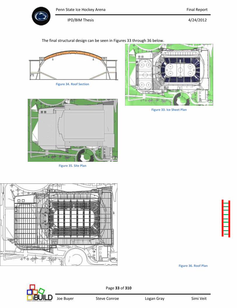
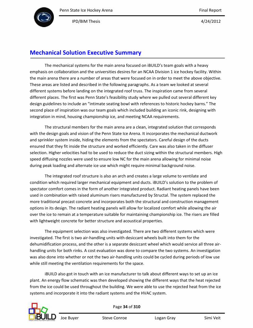
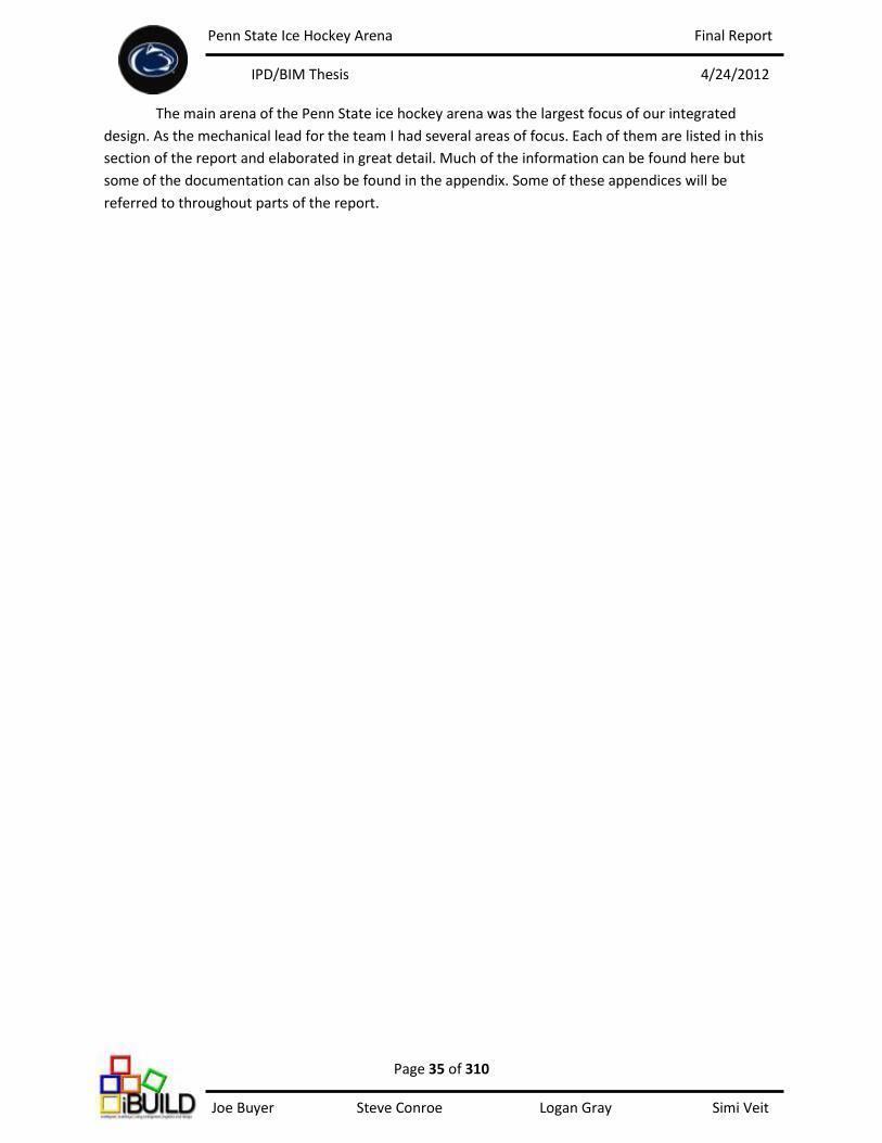
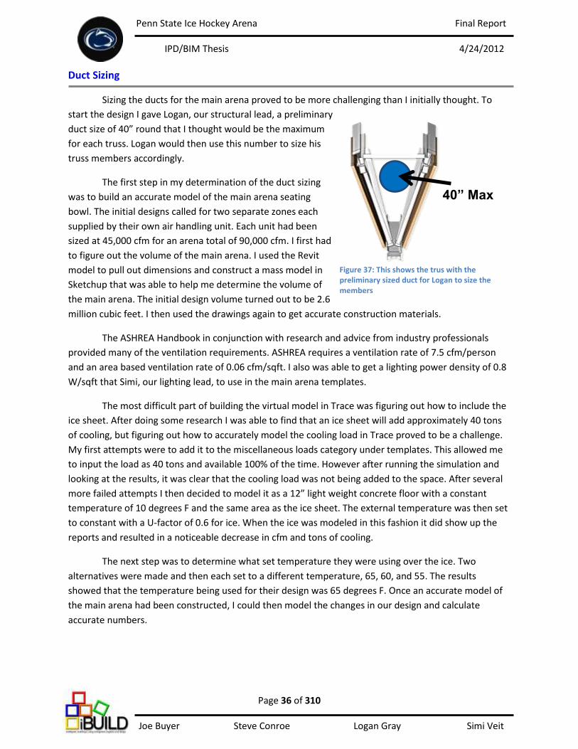
The final structural design can be seen in Figures 33 through 36 below.
Figure 34. Roof Section
Figure 35. Site Plan
Figure 36. Roof Plan
Figure 33. Ice Sheet Plan
V-Truss Purlins
Penn State Ice Hockey Arena Final Report
IPD/BIM Thesis 4/24/2012
Page 34 of 310 Joe Buyer Steve Conroe Logan Gray Simi Veit
Mechanical Solution Executive Summary
The mechanical systems for the main arena focused on iBUILD’s team goals with a heavy
emphasis on collaboration and the universities desires for an NCAA Division 1 ice hockey facility. Within
the main arena there are a number of areas that were focused on in order to meet the above objective.
These areas are listed and described in the following paragraphs. As a team we looked at several
different systems before landing on the integrated roof truss. The inspiration came from several
different places. The first was Penn State’s feasibility study where we pulled out several different key
design guidelines to include an “intimate seating bowl with references to historic hockey barns.” The
second place of inspiration was our team goals which included building an iconic rink, designing with
integration in mind, housing championship ice, and meeting NCAA requirements.
The structural members for the main arena are a clean, integrated solution that corresponds
with the design goals and vision of the Penn State Ice Arena. It incorporates the mechanical ductwork
and sprinkler system inside, hiding the elements from the spectators. Careful design of the ducts
ensured that they fit inside the structure and worked efficiently. Care was also taken in the diffuser
selection. Higher velocities had to be used to reduce the duct sizing within the structural members. High
speed diffusing nozzles were used to ensure low NC for the main arena allowing for minimal noise
during peak loading and alternate ice use which might require minimal background noise.
The integrated roof structure is also an arch and creates a large volume to ventilate and
condition which required larger mechanical equipment and ducts. iBUILD’s solution to the problem of
spectator comfort comes in the form of another integrated product. Radiant heating panels have been
used in combination with raised aluminum risers manufactured by Structal. The system replaced the
more traditional precast concrete and incorporates both the structural and construction management
options in its design. The radiant heating panels will allow for localized comfort while allowing the air
over the ice to remain at a temperature suitable for maintaining championship ice. The risers are filled
with lightweight concrete for better structure and acoustical properties.
The equipment selection was also investigated. There are two different systems which were
investigated. The first is two air-handling units with desiccant wheels built into them for the
dehumidification process, and the other is a separate desiccant wheel which would service all three air-
handling units for both rinks. A cost evaluation was done to compare the two systems. An investigation
was also done into whether or not the two air-handling units could be cycled during periods of low use
while still meeting the ventilation requirements for the space.
iBUILD also got in touch with an ice manufacturer to talk about different ways to set up an ice
plant. An energy flow schematic was then developed showing the different ways that the heat rejected
from the ice could be used throughout the building. We were able to use the rejected heat from the ice
systems and incorporate it into the radiant systems and the HVAC system.
Penn State Ice Hockey Arena Final Report
IPD/BIM Thesis 4/24/2012
Page 35 of 310 Joe Buyer Steve Conroe Logan Gray Simi Veit
The main arena of the Penn State ice hockey arena was the largest focus of our integrated
design. As the mechanical lead for the team I had several areas of focus. Each of them are listed in this
section of the report and elaborated in great detail. Much of the information can be found here but
some of the documentation can also be found in the appendix. Some of these appendices will be
referred to throughout parts of the report.
Penn State Ice Hockey Arena Final Report
IPD/BIM Thesis 4/24/2012
Page 36 of 310 Joe Buyer Steve Conroe Logan Gray Simi Veit
Duct Sizing
Sizing the ducts for the main arena proved to be more challenging than I initially thought. To
start the design I gave Logan, our structural lead, a preliminary
duct size of 40” round that I thought would be the maximum
for each truss. Logan would then use this number to size his
truss members accordingly.
The first step in my determination of the duct sizing
was to build an accurate model of the main arena seating
bowl. The initial designs called for two separate zones each
supplied by their own air handling unit. Each unit had been
sized at 45,000 cfm for an arena total of 90,000 cfm. I first had
to figure out the volume of the main arena. I used the Revit
model to pull out dimensions and construct a mass model in
Sketchup that was able to help me determine the volume of
the main arena. The initial design volume turned out to be 2.6
million cubic feet. I then used the drawings again to get accurate construction materials.
The ASHREA Handbook in conjunction with research and advice from industry professionals
provided many of the ventilation requirements. ASHREA requires a ventilation rate of 7.5 cfm/person
and an area based ventilation rate of 0.06 cfm/sqft. I also was able to get a lighting power density of 0.8
W/sqft that Simi, our lighting lead, to use in the main arena templates.
The most difficult part of building the virtual model in Trace was figuring out how to include the
ice sheet. After doing some research I was able to find that an ice sheet will add approximately 40 tons
of cooling, but figuring out how to accurately model the cooling load in Trace proved to be a challenge.
My first attempts were to add it to the miscellaneous loads category under templates. This allowed me
to input the load as 40 tons and available 100% of the time. However after running the simulation and
looking at the results, it was clear that the cooling load was not being added to the space. After several
more failed attempts I then decided to model it as a 12” light weight concrete floor with a constant
temperature of 10 degrees F and the same area as the ice sheet. The external temperature was then set
to constant with a U-factor of 0.6 for ice. When the ice was modeled in this fashion it did show up the
reports and resulted in a noticeable decrease in cfm and tons of cooling.
The next step was to determine what set temperature they were using over the ice. Two
alternatives were made and then each set to a different temperature, 65, 60, and 55. The results
showed that the temperature being used for their design was 65 degrees F. Once an accurate model of
the main arena had been constructed, I could then model the changes in our design and calculate
accurate numbers.
40” Max
Figure 37: This shows the trus with the preliminary sized duct for Logan to size the members

Penn State Ice Hockey Arena Final Report
IPD/BIM Thesis 4/24/2012
Page 37 of 310 Joe Buyer Steve Conroe Logan Gray Simi Veit
With the truss being an arch, we knew it would add considerable volume to the main arena.
Logan and I worked very closely to come up with a rise that would minimize his lateral thrust while
keeping the added volume to a minimum as well. He and I modeled several different designs before
falling on a 20’ rise which would add 985,000 cubic feet, a 38% increase in volume.
The next step for me was to determine the set temperature I would use in the main arena that
would best maintain championship ice. Research showed that the ideal rink temperature is down in the
area of 40 – 60 degrees F but that higher temperatures were preferred for spectator comfort. Since I
would be designing and utilizing a local heat source for the spectators, we decided to go with a lower set
temperature in the neighborhood of 55 – 60 degrees F. This however caused problems during the
summer months when much more cooling was needed. We were able to solve this problem by using a
high set temperature of 65 degrees F in the warmer months when the season was over, and keeping
lower temperatures during the colder months. After talking to industry professionals I decided to use
45% relative humidity which gave a dew point of 49 degrees F. Anything lower than this would require
an active desiccant system.
After having all these parameters in Trace I could now get an accurate model for our new arena
design. The reports showed that the bowl would require a maximum of 103,000 cfm, or 51,500 cfm per
unit. This was more than the initial 48,000 cfm per unit that I had initially estimated for.
Figure 40: This table is a summary of the trace reports which can be found in the appendix section of the report. The top table shows iBuilds design and the bottom is the original design.
20’ Rise
Figure 38: Shows the rise in the roof from original design Figure 39: Show the roof as it sits on a mass model

Penn State Ice Hockey Arena Final Report
IPD/BIM Thesis 4/24/2012
Page 38 of 310 Joe Buyer Steve Conroe Logan Gray Simi Veit
Each unit was designed to have its own branch and supply half of the arena. The main duct run
of each would run the length of the building where the trusses connected to its supports. There each
branch would then enter the truss and go over the ice sheet. There are eight trusses in the main arena
and each of them would house a branch. I took my results of 55,000 cfm per unit and used to calculate
the air distribution to each truss. The two end trusses would each receive 3,000 cfm while the other
branches would receive 6,000 cfm each.
I used two different design guides when sizing the ducts, the first was less than 0.1” wg, which
gave a main speed of 2500 fpm and a branch speed of 1400 fpm, and the second was 2000 fpm when
sizing the main, and 750 fpm when sizing the branches. When using the first method, I found that the air
speeds were too great and would likely cause acoustical issues when being diffused, so this left me with
the second option of sizing using 2000 fpm in the main, and 750 fpm in each branch.
Figure 42: Shows a section of the ducts as it runs through the structure.
3,000 CFM
6,000 CFM
1,600 CFM
Figure 41: gives a graphical representation of air flow in the ducts as described above.
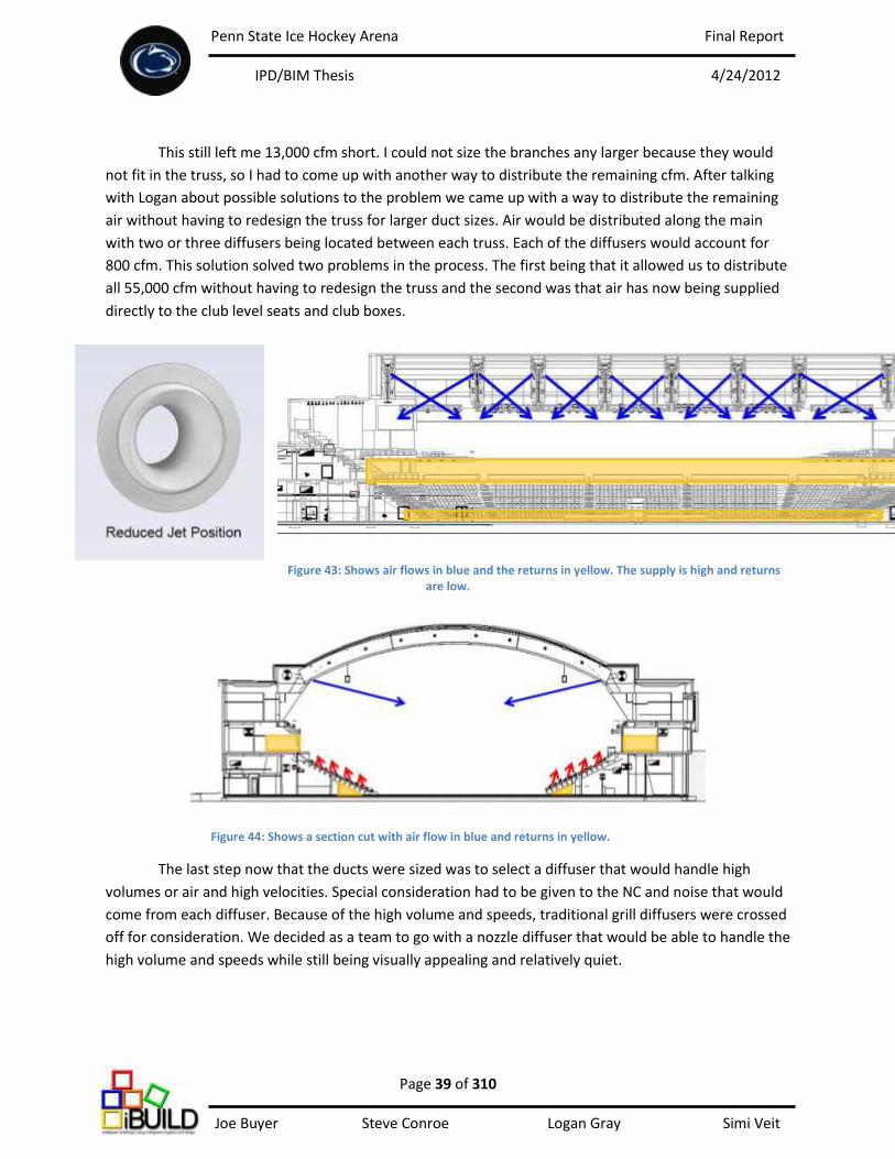
Penn State Ice Hockey Arena Final Report
IPD/BIM Thesis 4/24/2012
Page 39 of 310 Joe Buyer Steve Conroe Logan Gray Simi Veit
This still left me 13,000 cfm short. I could not size the branches any larger because they would
not fit in the truss, so I had to come up with another way to distribute the remaining cfm. After talking
with Logan about possible solutions to the problem we came up with a way to distribute the remaining
air without having to redesign the truss for larger duct sizes. Air would be distributed along the main
with two or three diffusers being located between each truss. Each of the diffusers would account for
800 cfm. This solution solved two problems in the process. The first being that it allowed us to distribute
all 55,000 cfm without having to redesign the truss and the second was that air has now being supplied
directly to the club level seats and club boxes.
Figure 43: Shows air flows in blue and the returns in yellow. The supply is high and returns are low.
Figure 44: Shows a section cut with air flow in blue and returns in yellow.
The last step now that the ducts were sized was to select a diffuser that would handle high
volumes or air and high velocities. Special consideration had to be given to the NC and noise that would
come from each diffuser. Because of the high volume and speeds, traditional grill diffusers were crossed
off for consideration. We decided as a team to go with a nozzle diffuser that would be able to handle the
high volume and speeds while still being visually appealing and relatively quiet.
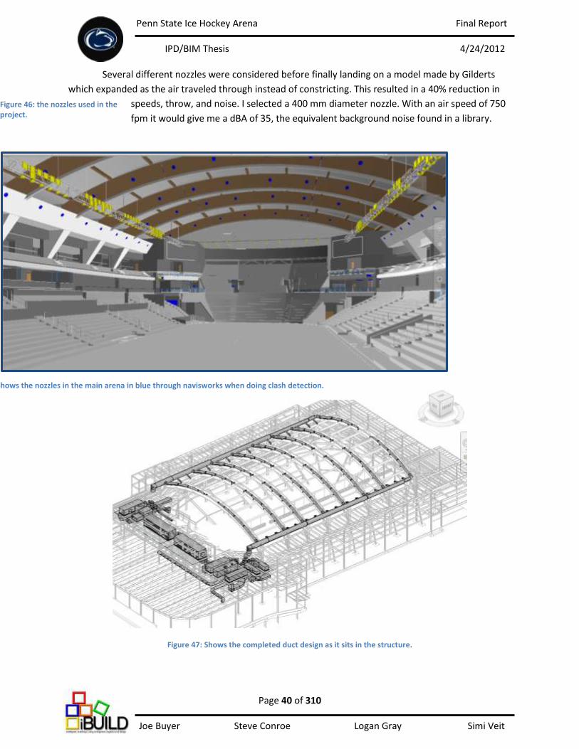
Penn State Ice Hockey Arena Final Report
IPD/BIM Thesis 4/24/2012
Page 40 of 310 Joe Buyer Steve Conroe Logan Gray Simi Veit
Several different nozzles were considered before finally landing on a model made by Gilderts
which expanded as the air traveled through instead of constricting. This resulted in a 40% reduction in
speeds, throw, and noise. I selected a 400 mm diameter nozzle. With an air speed of 750
fpm it would give me a dBA of 35, the equivalent background noise found in a library.
Figure 47: Shows the completed duct design as it sits in the structure.
Figure 46: the nozzles used in the project.
Figure 45: Shows the nozzles in the main arena in blue through navisworks when doing clash detection.
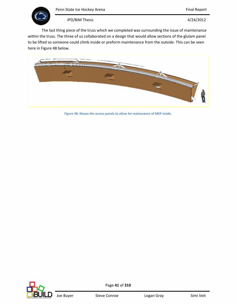
Penn State Ice Hockey Arena Final Report
IPD/BIM Thesis 4/24/2012
Page 41 of 310 Joe Buyer Steve Conroe Logan Gray Simi Veit
The last thing piece of the truss which we completed was surrounding the issue of maintenance
within the truss. The three of us collaborated on a design that would allow sections of the glulam panel
to be lifted so someone could climb inside or preform maintenance from the outside. This can be seen
here in Figure 48 below.
Figure 48: Shows the access panels to allow for mainenance of MEP inside.

Penn State Ice Hockey Arena Final Report
IPD/BIM Thesis 4/24/2012
Page 42 of 310 Joe Buyer Steve Conroe Logan Gray Simi Veit
Radiant Heating Panels
The idea of spectator comfort was important to our team. We wanted to maintain
championship ice while still providing a suitable game environment for the spectators. As the semester
progressed, the idea of a radiant floor evolved and took on different shapes until we landed on final
product that worked and was still relatively easy to construct and maintain.
The initial idea was to have a radiant floor with piping embedded into the precast concrete
risers. This would provide a warm mass with heat rising to the spectators seats just above. But this
solution provided a number of problems. I talked with a few precast concrete manufacturers and they
assured me that it could be done but at a considerable price increase. Another problem was the
maintenance that might be required over the life of the system. With the piping being embedded in the
concrete there would be no way to perform maintenance without destroying or replacing the risers.
I found an alternative solution from Structal, a
steel manufacturer. They had developed an extruded
aluminum riser which could replace the much heavier
precast concrete risers while still maintaining the same
structural properties of precast concrete. The riser is 2.5”
thick and could be left hollow, or filled with
polyurethane insulation or lightweight concrete. When
filled with light weight concrete the riser would weigh 8
pounds per sqft as opposed to the 100 pounds per sqft
of precast concrete.
After talking with Structal about the
specifications and code requirements I found that the risers had actually been considered for the
original proposed design but because at the time they had no way of fireproofing the underside it fell
through. I was told that the risers could now be fireproofed by laying down metal decking under the
risers and spraying the underside with fireproofing. This solution to fireproofing the risers meets all code
requirements.
I worked closely with Steve and Logan on the selection of this product. Because the structure
weighs considerably less than precast concrete risers, it requires less structural support for the dead
weight of each section. The weight also provides considerable advantages to the CM as well. More risers
can be delivered by fewer trucks because many can be stacked and delivered. Another advantage is the
crane needed to set the risers in place. Because the risers only weigh 8 pounds per sq. ft. the crane
needed will be much smaller. Savings will also take place in the speed of the erection process. Structal
assures me that no special training or labor is required to places the risers. Each riser snaps in place to
the top of the preceding riser.
Figure 49: Shows an unfilled alluminum decking by Structal.
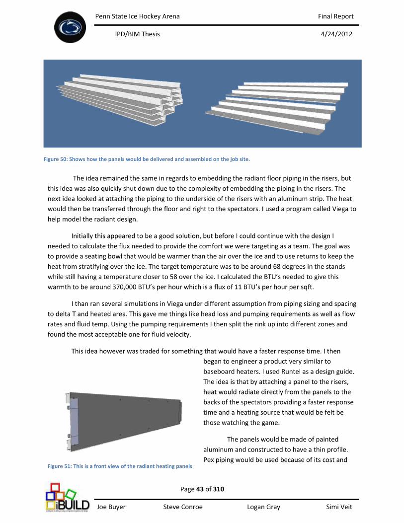
Penn State Ice Hockey Arena Final Report
IPD/BIM Thesis 4/24/2012
Page 43 of 310 Joe Buyer Steve Conroe Logan Gray Simi Veit
The idea remained the same in regards to embedding the radiant floor piping in the risers, but
this idea was also quickly shut down due to the complexity of embedding the piping in the risers. The
next idea looked at attaching the piping to the underside of the risers with an aluminum strip. The heat
would then be transferred through the floor and right to the spectators. I used a program called Viega to
help model the radiant design.
Initially this appeared to be a good solution, but before I could continue with the design I
needed to calculate the flux needed to provide the comfort we were targeting as a team. The goal was
to provide a seating bowl that would be warmer than the air over the ice and to use returns to keep the
heat from stratifying over the ice. The target temperature was to be around 68 degrees in the stands
while still having a temperature closer to 58 over the ice. I calculated the BTU’s needed to give this
warmth to be around 370,000 BTU’s per hour which is a flux of 11 BTU’s per hour per sqft.
I than ran several simulations in Viega under different assumption from piping sizing and spacing
to delta T and heated area. This gave me things like head loss and pumping requirements as well as flow
rates and fluid temp. Using the pumping requirements I then split the rink up into different zones and
found the most acceptable one for fluid velocity.
This idea however was traded for something that would have a faster response time. I then
began to engineer a product very similar to
baseboard heaters. I used Runtel as a design guide.
The idea is that by attaching a panel to the risers,
heat would radiate directly from the panels to the
backs of the spectators providing a faster response
time and a heating source that would be felt be
those watching the game.
The panels would be made of painted
aluminum and constructed to have a thin profile.
Pex piping would be used because of its cost and
Figure 50: Shows how the panels would be delivered and assembled on the job site.
Figure 51: This is a front view of the radiant heating panels

Penn State Ice Hockey Arena Final Report
IPD/BIM Thesis 4/24/2012
Page 44 of 310 Joe Buyer Steve Conroe Logan Gray Simi Veit
thermodynamic properties. A removable piece
would also exist at each connection point for
maintenance and pipe connection purposes. Finally
a seal would be placed on both ends of the panel to
keep spilled drinks from running between the riser
and the panel. The panels would be connected to
the riser via screws on the top and bottom of each
panel.
The panels were modeled as a grey body
using the following equation:
where ε is the emissivity, σ is the Stefan-Boltzmann constant, T is the temperature of the body in kelvin,
and A is the surface area of the body. The
answer is in watts which can then be
converted to BTU’s per hour.
By having two pipes at 6” spacing
and running water with a temperature of
140 degrees F with a delta T of 20 degrees F
through a 6’ long panel, I could achieve 457
BTU’s per hour per panel. With the seating
bowl being split into sections, it gives me a
flow of 1.06 gpm, which is an acceptable
fluid velocity. The total heat output from the
panels at its max design point is 460,000
BTU’s per hour and a flux of 15 BTU’s per hour per sqft.
Figure 52: This is a back view of the radient heating panels
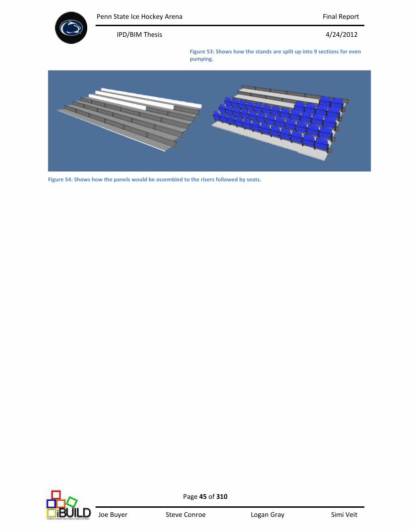
Penn State Ice Hockey Arena Final Report
IPD/BIM Thesis 4/24/2012
Page 45 of 310 Joe Buyer Steve Conroe Logan Gray Simi Veit
Figure 53: Shows how the stands are split up into 9 sections for even pumping.
Figure 54: Shows how the panels would be assembled to the risers followed by seats.

Penn State Ice Hockey Arena Final Report
IPD/BIM Thesis 4/24/2012
Page 46 of 310 Joe Buyer Steve Conroe Logan Gray Simi Veit
This solution not only meets the requirements for spectator comfort, but also continues to
streamline the construction process. By offering a delta T of 15 degrees around the spectators, they will
be much warmer than in traditional ice arenas while still maintaining high quality ice.
Figure 55: The figure above and bellow are a crude “CFD” model of how temperature would be distributed in the main arena.
Penn State Ice Hockey Arena Final Report
IPD/BIM Thesis 4/24/2012
Page 47 of 310 Joe Buyer Steve Conroe Logan Gray Simi Veit
AHU Selection
Another area I researched was the air handling unit selection for the main arena. For this section
I first looked into different ways to dehumidify the rink. I then compared two different systems in Trace
and also looked into the practicality of using an economizer on these units for the months when the air
outside would fall into the air requirements for conditioning the arena space.
ASHREA describes two ways of dehumidifying the air in an ice rink. The first is through a
desiccant wheel and the second is through a dehumidification unit (DHU). As I talked to industry
professionals I found that the design of these units are done by dew point, however it does without
saying that the more humidity control, the pricier the system is going to be.
At a dew point of 45 degrees F, fog is eliminated from the surface of the ice, and air above the
ice is prevented from reaching 100% relative humidity. This can be done with mechanical dehumidifiers
which cost less than active desiccant. At a dew point of 40 degrees F, dripping is eliminated; the dew
point is below the coldest surface in the roof structure, as well as all the advantages for a dew point of
45 degrees F. The conclusion that I was able to draw from this information was that a dew point well
below 45 would give us the best results and the better ice. However this would only be attainable with
an active desiccant system.
The original design of the main arena uses DHU’s which have desiccant wheels built into the
units. These were the first units I modeled in Trace to get a base which I could compare other systems
to. I then used the design of the Boston University Ice Arena’s rink supply system as a comparison. They
used AHU’s which were attached to a separate desiccant wheel. This design would require more roof
space for units in our design and this would be something I would have to keep in mind when selecting a
system. The AHU’s for the BU arena are a return-bypass system. This means that money is saved by not
having to reheat the air with coils, but instead uses the return air to heat the supply.
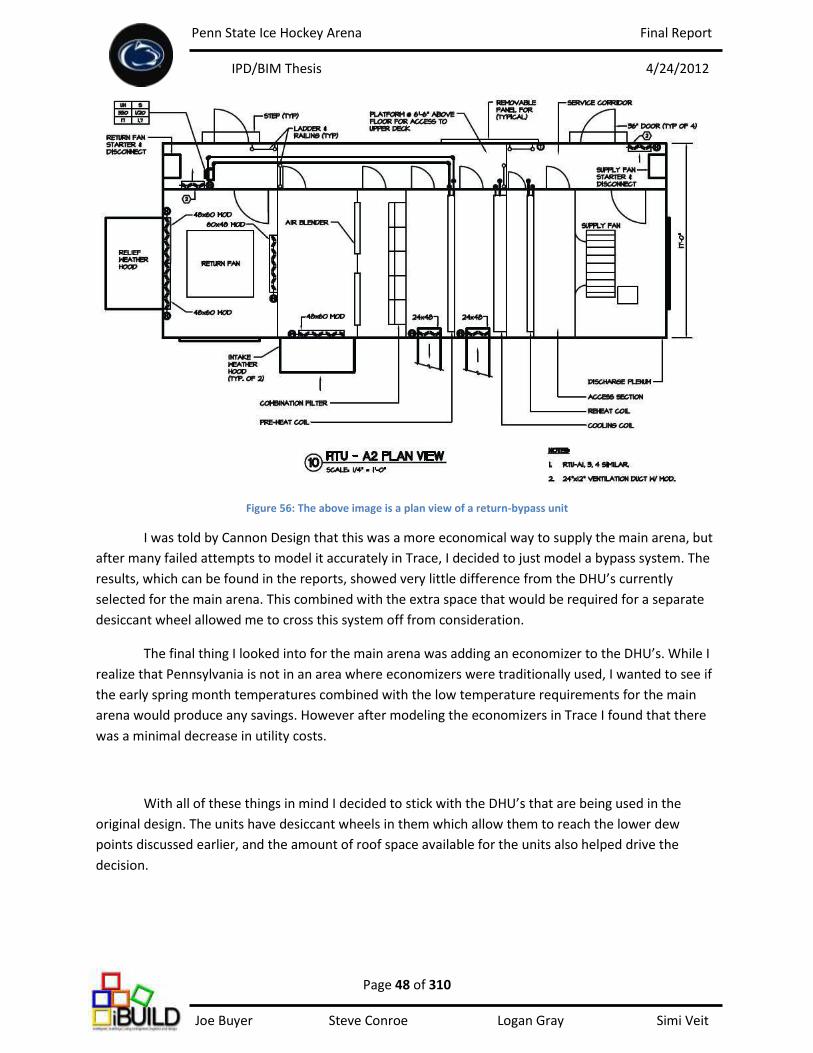
Penn State Ice Hockey Arena Final Report
IPD/BIM Thesis 4/24/2012
Page 48 of 310 Joe Buyer Steve Conroe Logan Gray Simi Veit
Figure 56: The above image is a plan view of a return-bypass unit
I was told by Cannon Design that this was a more economical way to supply the main arena, but
after many failed attempts to model it accurately in Trace, I decided to just model a bypass system. The
results, which can be found in the reports, showed very little difference from the DHU’s currently
selected for the main arena. This combined with the extra space that would be required for a separate
desiccant wheel allowed me to cross this system off from consideration.
The final thing I looked into for the main arena was adding an economizer to the DHU’s. While I
realize that Pennsylvania is not in an area where economizers were traditionally used, I wanted to see if
the early spring month temperatures combined with the low temperature requirements for the main
arena would produce any savings. However after modeling the economizers in Trace I found that there
was a minimal decrease in utility costs.
With all of these things in mind I decided to stick with the DHU’s that are being used in the
original design. The units have desiccant wheels in them which allow them to reach the lower dew
points discussed earlier, and the amount of roof space available for the units also helped drive the
decision.
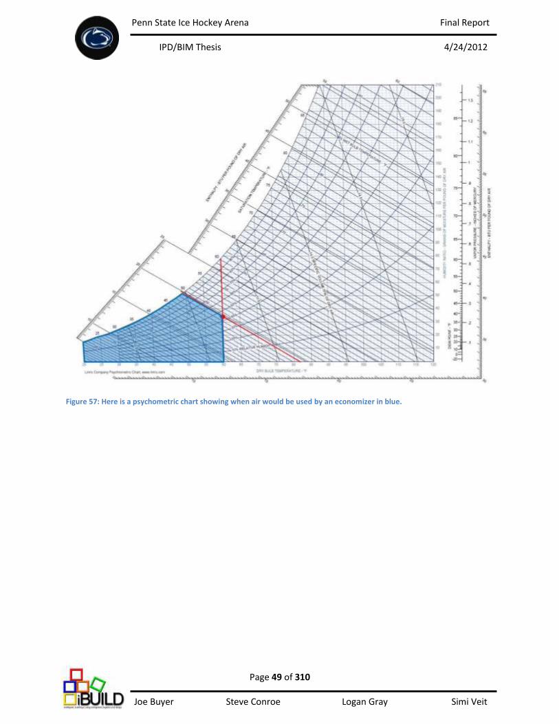
Penn State Ice Hockey Arena Final Report
IPD/BIM Thesis 4/24/2012
Page 49 of 310 Joe Buyer Steve Conroe Logan Gray Simi Veit
Figure 57: Here is a psychometric chart showing when air would be used by an economizer in blue.

Penn State Ice Hockey Arena Final Report
IPD/BIM Thesis 4/24/2012
Page 50 of 310 Joe Buyer Steve Conroe Logan Gray Simi Veit
Ice Plant Research
The last area of research for the main arena is the ice plant. At the onset of this project I was
under the impression that I was going to be able to model the entire ice plant. However I quickly learned
from industry professionals such as CIMCO that this would be almost impossible on my own. I found
that there are entire companies and industry professionals whose sole focus is designing these systems.
Through correspondence and research I found that a sheet of ice requires anywhere from 50 to
75 tons of cooling to operate and maintain the ice, to include recovering after resurfacing. This is the
equivalent to 900,000 to 1.2 million BTU’s per hour of heat rejection to the atmosphere. 200,000 to
400,000 BTU’s per hour are used in underfloor heating to prevent frost heave in the rink slab and in the
snowmelt pit. The balance of the heat can be used for a number of different ways to include hot water
preheat, space heating, and heating coils.
Based on the needs of the rink and the different ways to distribute the waste heat, I developed a
schematic energy flow diagram. This schematic system uses waste heat in hot water preheat, radiant
panel hot water preheat, underfloor heating to prevent frost heave, heating coils, and also distributed to
the cooling tower.
Figure 58: This is the energy flow schematic for the ice p lant.
Penn State Ice Hockey Arena Final Report
IPD/BIM Thesis 4/24/2012
Page 51 of 310 Joe Buyer Steve Conroe Logan Gray Simi Veit
Lighting/Electrical Solution Executive Summary
In order to make the main arena an iconic integrated space and meet NCAA Division One
requirements, multiple lighting and electrical systems needed to be considered. The first system was the
ice event lighting. To meet NCAA Division One national broadcasting requirements, there needs to be
precise illuminance levels and uniformity both horizontally and vertically. These values were measured
using AGi32 and 3D Studio Max. The design also had to avoid causing direct and reflected glare and
shadows for the players as well as the audience members. The 1000W metal halide fixtures are
mounted on strategically placed lighting platforms in order to get full coverage horizontally and
vertically. Lastly, in order to achieve the “black out scenario” there are shutters on the fixtures that close
in less than 3 seconds.
The next systems considered were the temporary lighting, theatrical effects, portable spotlights
still camera strobes, and scoreboard power loads. Since the arena may hold events such as concerts or
ice shows the electrical system needed to have the capability to power supplemental equipment that
may be brought in by outside tour companies. During the blackout there will be theatrical effect lighting
that is controlled from the control booth, mounted on the lighting stage system, along with a series of
high power camera strobes for still camera photography. An allowance was made in the power
distribution system for all of these elements as well as typical scoreboard power loads.
Throughout the stands there is house and emergency lighting. The house lighting is provided by
LED floodlights aimed at the stands from the platforms. This house lighting is a source of general
illumination (approximately 10 to 20 fc) to be used for spectator arrival, departure, maintenance, and
cleanup. As requested in the feasibility statement, the student section was designed to be brighter (2:1
ratio) than the rest of the stands to put focus on “Section E”. There are additional emergency LED
floodlights mounted to the lighting platforms, which provide emergency lighting of at least 8 fc.
The total design is less than ASHRAE 90.1 2010 power density requirements for the ice and the
stands, 3.01 w/sq. ft. and .43 w/sq. ft. respectively. Branch circuits, were designed to reflect the lighting
design and meet NEC 2011 requirements. The power distribution system for the arena lights was also
modeled in Revit. The loads from the electrical system design of the main arena was later used for
designing the size of the overall electrical system.
Most coordination for the lighting and electrical design of the main arena occurred with the structural
discipline. The location of the light stages and the total distributed weight of the light fixtures were the
main items that required specific communication. The integrated truss enclosing most of the feeders
that supply power to the different lighting systems required coordination as well. The feeders took up a
small compartment of the truss yet still needed to be coordinated using BIM with the structural and
mechanical discipline to avoid clashing.
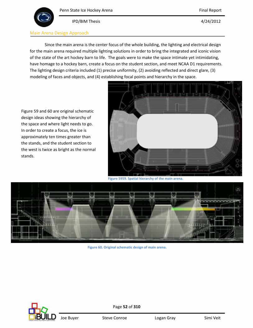
Penn State Ice Hockey Arena Final Report
IPD/BIM Thesis 4/24/2012
Page 52 of 310 Joe Buyer Steve Conroe Logan Gray Simi Veit
Main Arena Design Approach
Since the main arena is the center focus of the whole building, the lighting and electrical design
for the main arena required multiple lighting solutions in order to bring the integrated and iconic vision
of the state of the art hockey barn to life. The goals were to make the space intimate yet intimidating,
have homage to a hockey barn, create a focus on the student section, and meet NCAA D1 requirements.
The lighting design criteria included (1) precise uniformity, (2) avoiding reflected and direct glare, (3)
modeling of faces and objects, and (4) establishing focal points and hierarchy in the space.
Figure 59 and 60 are original schematic
design ideas showing the hierarchy of
the space and where light needs to go.
In order to create a focus, the ice is
approximately ten times greater than
the stands, and the student section to
the west is twice as bright as the normal
stands.
Figure 5959. Spatial hierarchy of the main arena.
Figure 60. Original schematic design of main arena.
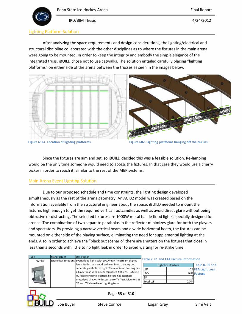
Penn State Ice Hockey Arena Final Report
IPD/BIM Thesis 4/24/2012
Page 53 of 310 Joe Buyer Steve Conroe Logan Gray Simi Veit
LLD 0.8
LDD 0.88
BF 1
Total LLF 0.704
Light Loss Factors
Type Manufactuer Description
F1, F1A Sportsliter Solutions Event flood lights with 1000W MH Arc stream aligned
lamp. Reflector is anodized aluminum creating two
seperate parabolas of light. The aluminum housing has
a black finish with a clear tempered flat lens. Fixture is
UL rated for damp location. Fixture has attached
motorized shades for instant on/off effect. Mounted at
57' and 55' above ice on lighting truss
Lighting Platform Solution
After analyzing the space requirements and design considerations, the lighting/electrical and
structural discipline collaborated with the other disciplines as to where the fixtures in the main arena
were going to be mounted. In order to keep the integrity and embody the simple elegance of the
integrated truss, iBUILD chose not to use catwalks. The solution entailed carefully placing “lighting
platforms” on either side of the arena between the trusses as seen in the images below.
Since the fixtures are aim and set, so iBUILD decided this was a feasible solution. Re-lamping
would be the only time someone would need to access the fixtures. In that case they would use a cherry
picker in order to reach it; similar to the rest of the MEP systems.
Main Arena Event Lighting Solution
Due to our proposed schedule and time constraints, the lighting design developed
simultaneously as the rest of the arena geometry. An AGi32 model was created based on the
information available from the structural engineer about the space. iBUILD needed to mount the
fixtures high enough to get the required vertical footcandles as well as avoid direct glare without being
obtrusive or distracting. The selected fixtures are 1000W metal halide flood lights, specially designed for
arenas. The combination of two separate parabolas in the reflector minimizes glare for both the players
and spectators. By providing a narrow vertical beam and a wide horizontal beam, the fixtures can be
mounted on either side of the playing surface, eliminating the need for supplemental lighting at the
ends. Also in order to achieve the “black out scenario” there are shutters on the fixtures that close in
less than 3 seconds with little to no light leak in order to avoid waiting for re-strike time.
Figure 6161. Location of lighting platforms. Figure 602. Lighting platforms hanging off the purlins.
Table 7. F1 and F1A Fixture Information
Table 8. F1 and F1A Light Loss Factors
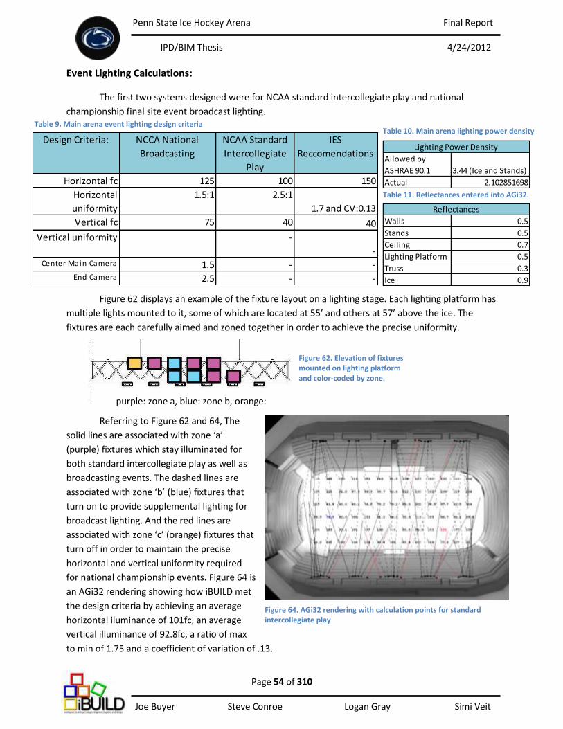
Penn State Ice Hockey Arena Final Report
IPD/BIM Thesis 4/24/2012
Page 54 of 310 Joe Buyer Steve Conroe Logan Gray Simi Veit
Walls 0.5
Stands 0.5
Ceiling 0.7
Lighting Platform 0.5
Truss 0.3
Ice 0.9
Reflectances
Allowed by
ASHRAE 90.1 3.44 (Ice and Stands)
Actual 2.102851698
Lighting Power DensityDesign Criteria: NCCA National
Broadcasting
NCAA Standard
Intercollegiate
Play
IES
Reccomendations
Horizontal fc 125 100 150
Horizontal
uniformity
1.5:1 2.5:1
1.7 and CV:0.13
Vertical fc 75 40 40
Vertical uniformity -
-Center Main Camera 1.5 - -
End Camera 2.5 - -
Figure 64. AGi32 rendering with calculation points for standard intercollegiate play
Event Lighting Calculations:
The first two systems designed were for NCAA standard intercollegiate play and national
championship final site event broadcast lighting.
Figure 62 displays an example of the fixture layout on a lighting stage. Each lighting platform has
multiple lights mounted to it, some of which are located at 55’ and others at 57’ above the ice. The
fixtures are each carefully aimed and zoned together in order to achieve the precise uniformity.
Referring to Figure 62 and 64, The
solid lines are associated with zone ‘a’
(purple) fixtures which stay illuminated for
both standard intercollegiate play as well as
broadcasting events. The dashed lines are
associated with zone ‘b’ (blue) fixtures that
turn on to provide supplemental lighting for
broadcast lighting. And the red lines are
associated with zone ‘c’ (orange) fixtures that
turn off in order to maintain the precise
horizontal and vertical uniformity required
for national championship events. Figure 64 is
an AGi32 rendering showing how iBUILD met
the design criteria by achieving an average
horizontal iluminance of 101fc, an average
vertical illuminance of 92.8fc, a ratio of max
to min of 1.75 and a coefficient of variation of .13.
purple: zone a, blue: zone b, orange:
zone c
Table 11. Reflectances entered into AGi32.
Table 9. Main arena event lighting design criteria Table 10. Main arena lighting power density
Figure 62. Elevation of fixtures mounted on lighting platform and color-coded by zone.
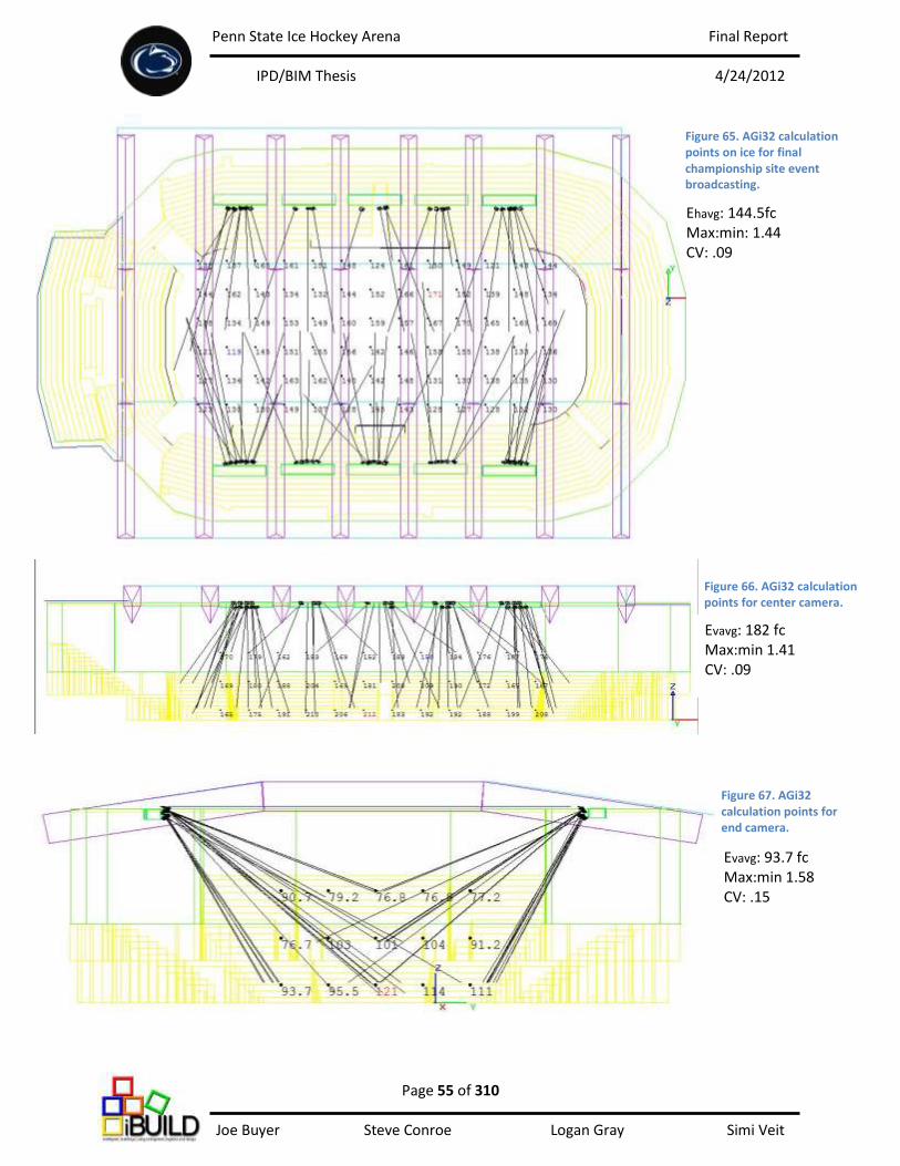
Penn State Ice Hockey Arena Final Report
IPD/BIM Thesis 4/24/2012
Page 55 of 310 Joe Buyer Steve Conroe Logan Gray Simi Veit
Evavg: 182 fc Max:min 1.41 CV: .09
Evavg: 93.7 fc Max:min 1.58 CV: .15
Figure 65. AGi32 calculation points on ice for final championship site event broadcasting.
Figure 66. AGi32 calculation points for center camera.
Figure 67. AGi32 calculation points for end camera.
Ehavg: 144.5fc Max:min: 1.44 CV: .09
Penn State Ice Hockey Arena Final Report
IPD/BIM Thesis 4/24/2012
Page 56 of 310 Joe Buyer Steve Conroe Logan Gray Simi Veit
Type Manufactuer Description
F13 Robe ColorSpot 575 Movable light that includes two separate gobo wheels
and two separate color wheels. Contains a dichroic
glass reflector and 15, 18 and 22 degree remotely
adjustable angles.
Main Arena Theatrical Lighting Solution
The next set of systems considered were the theatrical effects, portable spotlights, still camera
strobes, and scoreboard power loads. Since the arena may hold events such as concerts or ice shows the
electrical system needs to have the capability to power supplemental equipment that may be brought in
by outside tour companies. This is all powered from the show power room located on the event level.
There are 3 distribution panels located in the show power room on the event level that provide power
for these electrical loads. (1) 480Y/277 800A 14KAIC and (2) 208Y/120 400A 22KAIC are both connected
to the first main switchboard, and (3) 208Y/120 1000A 22KAIC is connected to the second main
switchboard.
During the blackout there will be theatrical effect lighting that is controlled from the control
booth, mounted on the lighting platform system, along with a series of high power camera strobes for
still camera photography. The theatrical effects are accomplished by a series of ColorSpot 575.
It was discovered that an outside theater and broadcast professional would need to be consulted to
figure out the best locations for the special photography lighting, but space was left available for these
fixtures on the lighting platforms and panel boards.
Table 12. F13 Fixture information
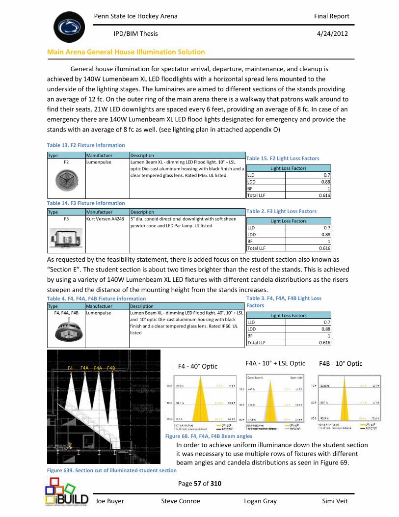
Penn State Ice Hockey Arena Final Report
IPD/BIM Thesis 4/24/2012
Page 57 of 310 Joe Buyer Steve Conroe Logan Gray Simi Veit
LLD 0.7
LDD 0.88
BF 1
Total LLF 0.616
Light Loss Factors
Type Manufactuer Description
F4, F4A, F4B Lumenpulse Lumen Beam XL - dimming LED Flood light. 40°, 10° + LSL
and 10° optic Die-cast aluminum housing with black
finish and a clear tempered glass lens. Rated IP66. UL
listed
LLD 0.7
LDD 0.88
BF 1
Total LLF 0.616
Light Loss Factors
Type Manufactuer Description
F2 Lumenpulse Lumen Beam XL - dimming LED Flood light. 10° + LSL
optic Die-cast aluminum housing with black finish and a
clear tempered glass lens. Rated IP66. UL listed
Type Manufactuer Description
F3 Kurt Versen A4248 5" dia. conoid directional downlight with soft sheen
pewter cone and LED Par lamp. UL listed
Main Arena General House Illumination Solution
General house illumination for spectator arrival, departure, maintenance, and cleanup is
achieved by 140W Lumenbeam XL LED floodlights with a horizontal spread lens mounted to the
underside of the lighting stages. The luminaires are aimed to different sections of the stands providing
an average of 12 fc. On the outer ring of the main arena there is a walkway that patrons walk around to
find their seats. 21W LED downlights are spaced every 6 feet, providing an average of 8 fc. In case of an
emergency there are 140W Lumenbeam XL LED flood lights designated for emergency and provide the
stands with an average of 8 fc as well. (see lighting plan in attached appendix O)
Table 13. F2 Fixture information
As requested by the feasibility statement, there is added focus on the student section also known as
“Section E”. The student section is about two times brighter than the rest of the stands. This is achieved
by using a variety of 140W Lumenbeam XL LED fixtures with different candela distributions as the risers
steepen and the distance of the mounting height from the stands increases.
In order to achieve uniform illuminance down the student section it was necessary to use multiple rows of fixtures with different beam angles and candela distributions as seen in Figure 69.
F4 F4A F4A F4B F4 - 40° Optic F4A - 10° + LSL Optic
LLD 0.7
LDD 0.88
BF 1
Total LLF 0.616
Light Loss Factors
Table 15. F2 Light Loss Factors
Table 14. F3 Fixture information
Table 2. F3 Light Loss Factors
Table 4. F4, F4A, F4B Fixture information Table 3. F4, F4A, F4B Light Loss Factors
Figure 639. Section cut of illuminated student section
F4B - 10° Optic F4 - 40° Optic F4A - 10° + LSL Optic
Figure 68. F4, F4A, F4B Beam angles
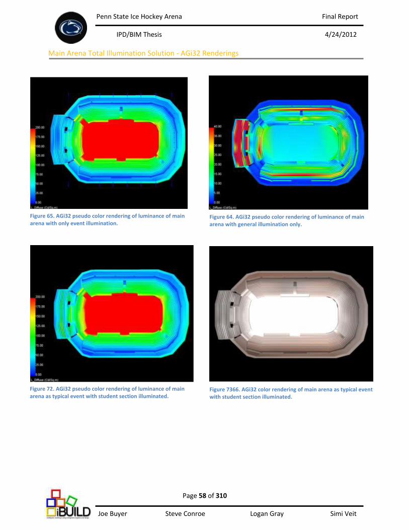
Penn State Ice Hockey Arena Final Report
IPD/BIM Thesis 4/24/2012
Page 58 of 310 Joe Buyer Steve Conroe Logan Gray Simi Veit
Figure 64. AGi32 pseudo color rendering of luminance of main arena with general illumination only.
Main Arena Total Illumination Solution - AGi32 Renderings
Figure 65. AGi32 pseudo color rendering of luminance of main arena with only event illumination.
Figure 7366. AGi32 color rendering of main arena as typical event with student section illuminated.
Figure 72. AGi32 pseudo color rendering of luminance of main arena as typical event with student section illuminated.
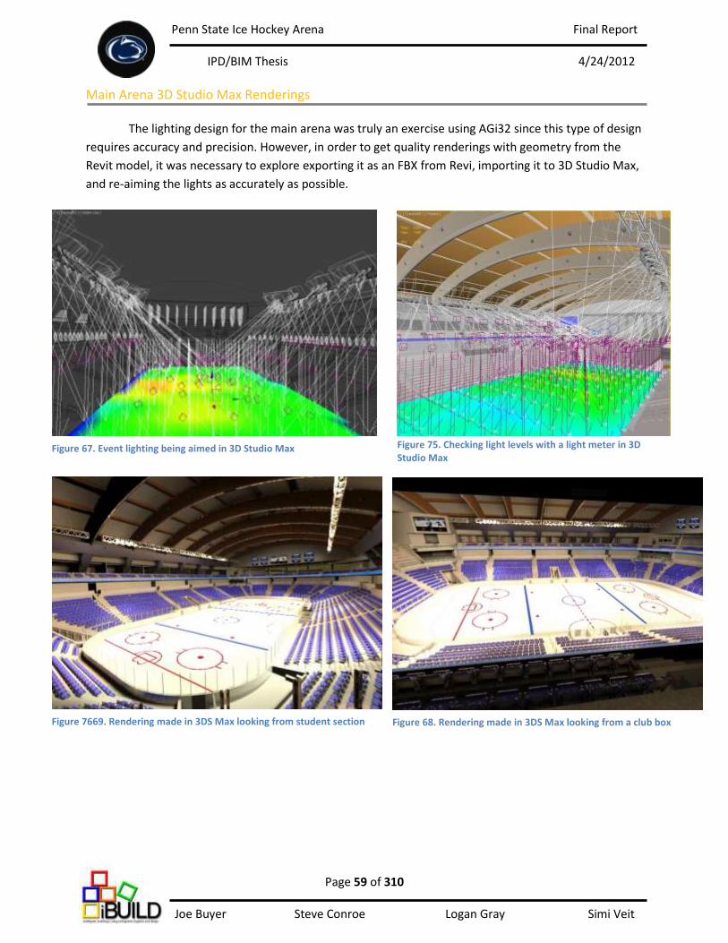
Penn State Ice Hockey Arena Final Report
IPD/BIM Thesis 4/24/2012
Page 59 of 310 Joe Buyer Steve Conroe Logan Gray Simi Veit
Main Arena 3D Studio Max Renderings
The lighting design for the main arena was truly an exercise using AGi32 since this type of design
requires accuracy and precision. However, in order to get quality renderings with geometry from the
Revit model, it was necessary to explore exporting it as an FBX from Revi, importing it to 3D Studio Max,
and re-aiming the lights as accurately as possible.
Figure 75. Checking light levels with a light meter in 3D Studio Max
Figure 67. Event lighting being aimed in 3D Studio Max
Figure 7669. Rendering made in 3DS Max looking from student section Figure 68. Rendering made in 3DS Max looking from a club box
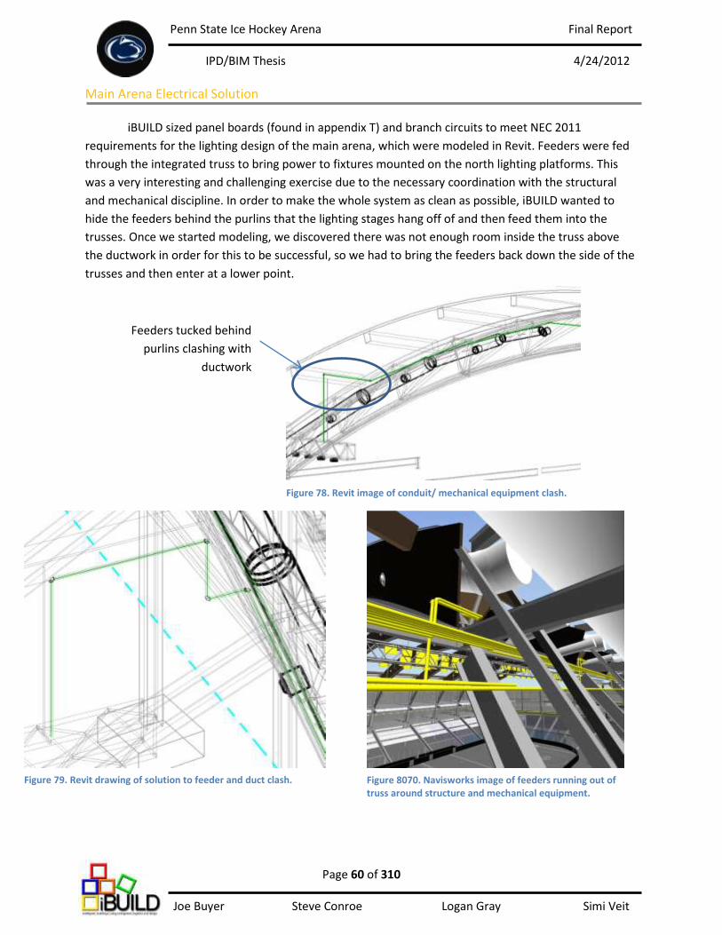
Penn State Ice Hockey Arena Final Report
IPD/BIM Thesis 4/24/2012
Page 60 of 310 Joe Buyer Steve Conroe Logan Gray Simi Veit
Main Arena Electrical Solution
iBUILD sized panel boards (found in appendix T) and branch circuits to meet NEC 2011
requirements for the lighting design of the main arena, which were modeled in Revit. Feeders were fed
through the integrated truss to bring power to fixtures mounted on the north lighting platforms. This
was a very interesting and challenging exercise due to the necessary coordination with the structural
and mechanical discipline. In order to make the whole system as clean as possible, iBUILD wanted to
hide the feeders behind the purlins that the lighting stages hang off of and then feed them into the
trusses. Once we started modeling, we discovered there was not enough room inside the truss above
the ductwork in order for this to be successful, so we had to bring the feeders back down the side of the
trusses and then enter at a lower point.
Feeders tucked behind
purlins clashing with
ductwork
Figure 78. Revit image of conduit/ mechanical equipment clash.
Figure 79. Revit drawing of solution to feeder and duct clash. Figure 8070. Navisworks image of feeders running out of truss around structure and mechanical equipment.

Penn State Ice Hockey Arena Final Report
IPD/BIM Thesis 4/24/2012
Page 61 of 310 Joe Buyer Steve Conroe Logan Gray Simi Veit
Main Arena Lighting and Electrical Conclusion
The lighting and electrical solution for the main arena closely coordinated with the structural
and mechanical disciplines in order to achieve the goals and design criteria for the space. The location of
the light stages and the total distributed weight of the light fixtures were the main items that required
communication with the structural engineering student. Due to the fact iBUILD chose not to use a
catwalk system; it was definitely a challenge to achieve accurate and uniform light levels. After many
hours of working with AGi32, the lighting/electrical engineering student was able to reach an acceptable
solution that met the NCAA criteria. The other challenge of the main arena was coordinating with the
mechanical ductwork through the integrated truss. This is where BIM became very useful in the design
process. Since the ductwork and structure were already modeled in Revit, the feeders had to be
designed around them. By taking this design initiative, when the model was run in Navisworks, there
was zero clashing between the disciplines. In a real project, having access to these softwares could save
millions of dollars during construction and make the whole process flow a lot smoother.
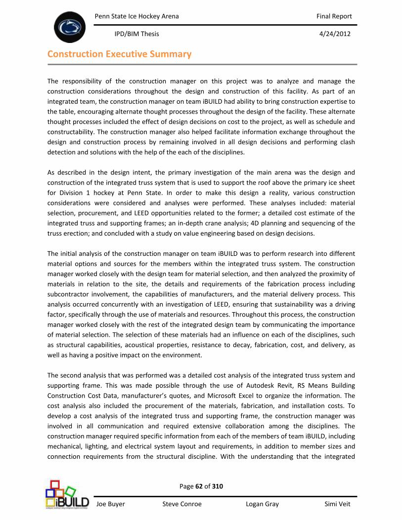
Penn State Ice Hockey Arena Final Report
IPD/BIM Thesis 4/24/2012
Page 62 of 310 Joe Buyer Steve Conroe Logan Gray Simi Veit
Construction Executive Summary
The responsibility of the construction manager on this project was to analyze and manage the
construction considerations throughout the design and construction of this facility. As part of an
integrated team, the construction manager on team iBUILD had ability to bring construction expertise to
the table, encouraging alternate thought processes throughout the design of the facility. These alternate
thought processes included the effect of design decisions on cost to the project, as well as schedule and
constructability. The construction manager also helped facilitate information exchange throughout the
design and construction process by remaining involved in all design decisions and performing clash
detection and solutions with the help of the each of the disciplines.
As described in the design intent, the primary investigation of the main arena was the design and
construction of the integrated truss system that is used to support the roof above the primary ice sheet
for Division 1 hockey at Penn State. In order to make this design a reality, various construction
considerations were considered and analyses were performed. These analyses included: material
selection, procurement, and LEED opportunities related to the former; a detailed cost estimate of the
integrated truss and supporting frames; an in-depth crane analysis; 4D planning and sequencing of the
truss erection; and concluded with a study on value engineering based on design decisions.
The initial analysis of the construction manager on team iBUILD was to perform research into different
material options and sources for the members within the integrated truss system. The construction
manager worked closely with the design team for material selection, and then analyzed the proximity of
materials in relation to the site, the details and requirements of the fabrication process including
subcontractor involvement, the capabilities of manufacturers, and the material delivery process. This
analysis occurred concurrently with an investigation of LEED, ensuring that sustainability was a driving
factor, specifically through the use of materials and resources. Throughout this process, the construction
manager worked closely with the rest of the integrated design team by communicating the importance
of material selection. The selection of these materials had an influence on each of the disciplines, such
as structural capabilities, acoustical properties, resistance to decay, fabrication, cost, and delivery, as
well as having a positive impact on the environment.
The second analysis that was performed was a detailed cost analysis of the integrated truss system and
supporting frame. This was made possible through the use of Autodesk Revit, RS Means Building
Construction Cost Data, manufacturer’s quotes, and Microsoft Excel to organize the information. The
cost analysis also included the procurement of the materials, fabrication, and installation costs. To
develop a cost analysis of the integrated truss and supporting frame, the construction manager was
involved in all communication and required extensive collaboration among the disciplines. The
construction manager required specific information from each of the members of team iBUILD, including
mechanical, lighting, and electrical system layout and requirements, in addition to member sizes and
connection requirements from the structural discipline. With the understanding that the integrated
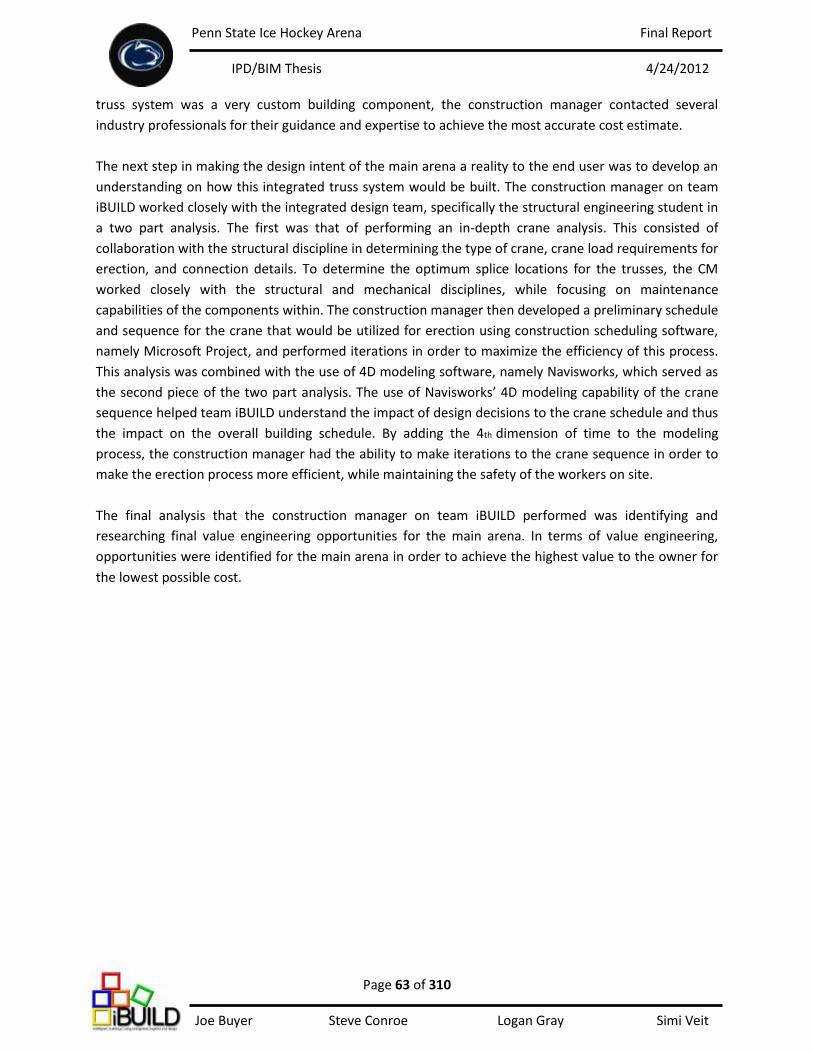
Penn State Ice Hockey Arena Final Report
IPD/BIM Thesis 4/24/2012
Page 63 of 310 Joe Buyer Steve Conroe Logan Gray Simi Veit
truss system was a very custom building component, the construction manager contacted several
industry professionals for their guidance and expertise to achieve the most accurate cost estimate.
The next step in making the design intent of the main arena a reality to the end user was to develop an
understanding on how this integrated truss system would be built. The construction manager on team
iBUILD worked closely with the integrated design team, specifically the structural engineering student in
a two part analysis. The first was that of performing an in-depth crane analysis. This consisted of
collaboration with the structural discipline in determining the type of crane, crane load requirements for
erection, and connection details. To determine the optimum splice locations for the trusses, the CM
worked closely with the structural and mechanical disciplines, while focusing on maintenance
capabilities of the components within. The construction manager then developed a preliminary schedule
and sequence for the crane that would be utilized for erection using construction scheduling software,
namely Microsoft Project, and performed iterations in order to maximize the efficiency of this process.
This analysis was combined with the use of 4D modeling software, namely Navisworks, which served as
the second piece of the two part analysis. The use of Navisworks’ 4D modeling capability of the crane
sequence helped team iBUILD understand the impact of design decisions to the crane schedule and thus
the impact on the overall building schedule. By adding the 4th dimension of time to the modeling
process, the construction manager had the ability to make iterations to the crane sequence in order to
make the erection process more efficient, while maintaining the safety of the workers on site.
The final analysis that the construction manager on team iBUILD performed was identifying and
researching final value engineering opportunities for the main arena. In terms of value engineering,
opportunities were identified for the main arena in order to achieve the highest value to the owner for
the lowest possible cost.
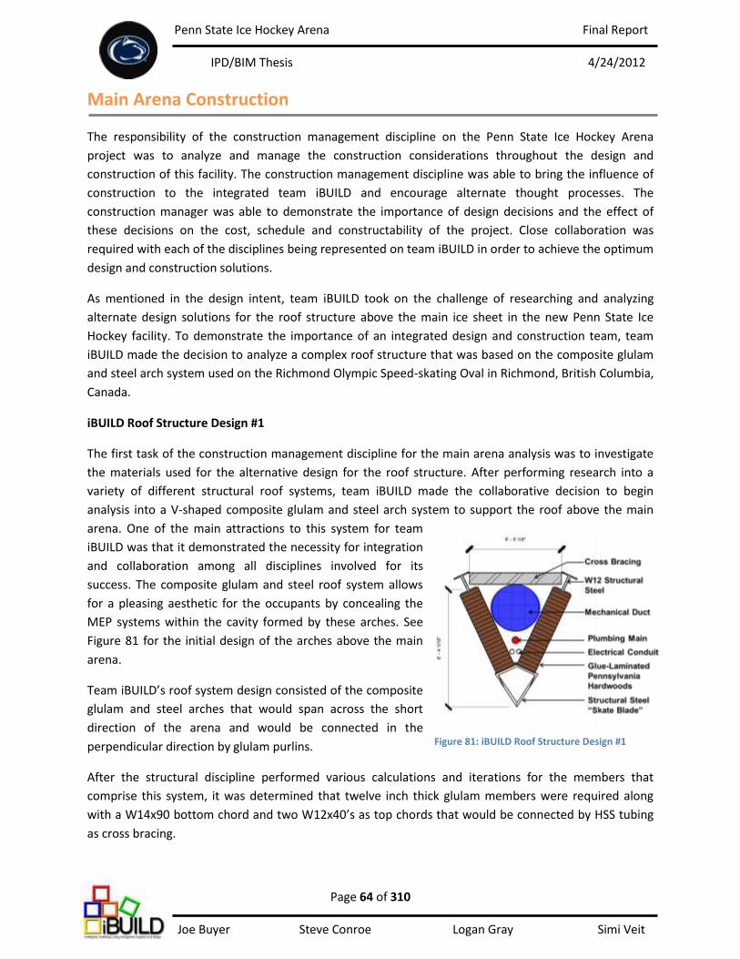
Penn State Ice Hockey Arena Final Report
IPD/BIM Thesis 4/24/2012
Page 64 of 310 Joe Buyer Steve Conroe Logan Gray Simi Veit
Main Arena Construction The responsibility of the construction management discipline on the Penn State Ice Hockey Arena
project was to analyze and manage the construction considerations throughout the design and
construction of this facility. The construction management discipline was able to bring the influence of
construction to the integrated team iBUILD and encourage alternate thought processes. The
construction manager was able to demonstrate the importance of design decisions and the effect of
these decisions on the cost, schedule and constructability of the project. Close collaboration was
required with each of the disciplines being represented on team iBUILD in order to achieve the optimum
design and construction solutions.
As mentioned in the design intent, team iBUILD took on the challenge of researching and analyzing
alternate design solutions for the roof structure above the main ice sheet in the new Penn State Ice
Hockey facility. To demonstrate the importance of an integrated design and construction team, team
iBUILD made the decision to analyze a complex roof structure that was based on the composite glulam
and steel arch system used on the Richmond Olympic Speed-skating Oval in Richmond, British Columbia,
Canada.
iBUILD Roof Structure Design #1
The first task of the construction management discipline for the main arena analysis was to investigate
the materials used for the alternative design for the roof structure. After performing research into a
variety of different structural roof systems, team iBUILD made the collaborative decision to begin
analysis into a V-shaped composite glulam and steel arch system to support the roof above the main
arena. One of the main attractions to this system for team
iBUILD was that it demonstrated the necessity for integration
and collaboration among all disciplines involved for its
success. The composite glulam and steel roof system allows
for a pleasing aesthetic for the occupants by concealing the
MEP systems within the cavity formed by these arches. See
Figure 81 for the initial design of the arches above the main
arena.
Team iBUILD’s roof system design consisted of the composite
glulam and steel arches that would span across the short
direction of the arena and would be connected in the
perpendicular direction by glulam purlins.
After the structural discipline performed various calculations and iterations for the members that
comprise this system, it was determined that twelve inch thick glulam members were required along
with a W14x90 bottom chord and two W12x40’s as top chords that would be connected by HSS tubing
as cross bracing.
Figure 81: iBUILD Roof Structure Design #1
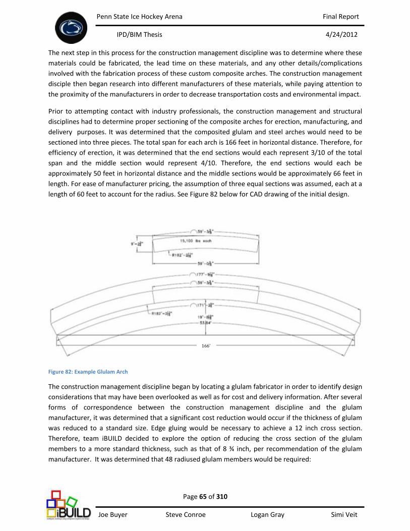
Penn State Ice Hockey Arena Final Report
IPD/BIM Thesis 4/24/2012
Page 65 of 310 Joe Buyer Steve Conroe Logan Gray Simi Veit
The next step in this process for the construction management discipline was to determine where these
materials could be fabricated, the lead time on these materials, and any other details/complications
involved with the fabrication process of these custom composite arches. The construction management
disciple then began research into different manufacturers of these materials, while paying attention to
the proximity of the manufacturers in order to decrease transportation costs and environmental impact.
Prior to attempting contact with industry professionals, the construction management and structural
disciplines had to determine proper sectioning of the composite arches for erection, manufacturing, and
delivery purposes. It was determined that the composited glulam and steel arches would need to be
sectioned into three pieces. The total span for each arch is 166 feet in horizontal distance. Therefore, for
efficiency of erection, it was determined that the end sections would each represent 3/10 of the total
span and the middle section would represent 4/10. Therefore, the end sections would each be
approximately 50 feet in horizontal distance and the middle sections would be approximately 66 feet in
length. For ease of manufacturer pricing, the assumption of three equal sections was assumed, each at a
length of 60 feet to account for the radius. See Figure 82 below for CAD drawing of the initial design.
Figure 82: Example Glulam Arch
The construction management discipline began by locating a glulam fabricator in order to identify design
considerations that may have been overlooked as well as for cost and delivery information. After several
forms of correspondence between the construction management discipline and the glulam
manufacturer, it was determined that a significant cost reduction would occur if the thickness of glulam
was reduced to a standard size. Edge gluing would be necessary to achieve a 12 inch cross section.
Therefore, team iBUILD decided to explore the option of reducing the cross section of the glulam
members to a more standard thickness, such as that of 8 ¾ inch, per recommendation of the glulam
manufacturer. It was determined that 48 radiused glulam members would be required:
166’

Penn State Ice Hockey Arena Final Report
IPD/BIM Thesis 4/24/2012
Page 66 of 310 Joe Buyer Steve Conroe Logan Gray Simi Veit
Team iBUILD’s design intent from the beginning was to incorporate Pennsylvania’s supply of hardwoods
into the design of the roof structure for the main arena. Therefore, a collaborative decision was made to
utilize that of Red Maple for the glulam members. Team iBUILD was aware that other options for wood
products that would be more readily available and have better structural design values, such as
southern yellow pine, but the decision was made to incorporate PA hardwoods for aesthetic value as
well as that of reduced environmental impact.
Another consideration for the glulam manufacturer was that of the cutouts for the mechanical diffusers.
This required collaboration among the construction management, structural, and mechanical disciplines
on team iBUILD in order to properly engineer the system as a whole. The spacing of the diffuser cutouts
had to occur in locations that would not conflict with splice locations for erection purposes. In order to
ensure the problem would not occur in the field, team iBUILD utilized Autodesk Revit platforms to
model the mechanical components within the truss and link these to the structural model to achieve the
optimum design solution. The conclusion was that 104 cutouts for diffusers would be required. The
middle six arches would have a total of 16 cutouts for diffusers (eight per side – evenly spaced). The
arches on each of the far ends of the arena would only have eight total cutouts and would be located on
the side facing the ice.
iBUILD Roof Structure Design #2 and Value Engineering Analysis
Following more discussions with industry professionals, it was recommended that team iBUILD could
explore the design of a steel truss system with architectural glulam paneling versus structural glulam
members connected by steel bracing. As a result of these discussions, team iBUILD took the initiative to
redesign the roof structure with that of steel arches and architectural glulam paneling in order to
perform a value engineering analysis of the roof structure. The steel arches with glulam paneling would
achieve the same aesthetic as the composite glulam and steel arches and would most likely result in a
cost reduction.
In terms of the structure that would connect the composite glulam and steel arches to one another,
team iBUILD decided to continue the glulam theme for the roof structure. After conducting structural
analysis, it was determined that glulam purlins would connect between each composite arch.
After all design considerations were finalized, the construction management discipline contacted the
glulam manufacturer with the project specifications. After back and forth correspondence, a quotation
was produced for each of team iBUILD’s design for the glulam components in the roof structure. The
quotation included that of the composite glulam and steel arches versus that of the steel arches with
glulam panels, as well as the glulam purlins. See Tables 19 and 20 below for a breakdown of the cost of
the structural glulam members for both of team iBUILD’s designs for the roof structure:
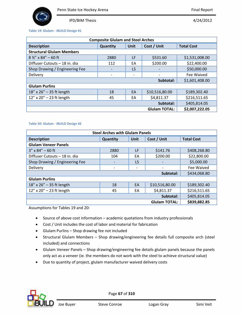
Penn State Ice Hockey Arena Final Report
IPD/BIM Thesis 4/24/2012
Page 67 of 310 Joe Buyer Steve Conroe Logan Gray Simi Veit
Table 19: Glulam - iBUILD Design #1
Composite Glulam and Steel Arches
Description Quantity Unit Cost / Unit Total Cost
Structural Glulam Members
8 ¾” x 84” – 60 ft 2880 LF $531.60 $1,531,008.00
Diffuser Cutouts – 18 in. dia 112 EA $200.00 $22,400.00
Shop Drawing / Engineering Fee - LS - $50,000.00
Delivery - - - Fee Waived
Subtotal: $1,601,408.00
Glulam Purlins
18” x 26” – 35 ft length 18 EA $10,516,80.00 $189,302.40
12” x 20” – 23 ft length 45 EA $4,811.37 $216,511.65
Subtotal: $405,814.05
Glulam TOTAL: $2,007,222.05
Table 50: Glulam - iBUILD Design #2
Steel Arches with Glulam Panels
Description Quantity Unit Cost / Unit Total Cost
Glulam Veneer Panels
3” x 84” – 60 ft 2880 LF $141.76 $408,268.80
Diffuser Cutouts – 18 in. dia 104 EA $200.00 $22,800.00
Shop Drawing / Engineering Fee - LS - $5,000.00
Delivery - - - Fee Waived
Subtotal: $434,068.80
Glulam Purlins
18” x 26” – 35 ft length 18 EA $10,516,80.00 $189,302.40
12” x 20” – 23 ft length 45 EA $4,811.37 $216,511.65
Subtotal: $405,814.05
Glulam TOTAL: $839,882.85
Assumptions for Tables 19 and 20:
Source of above cost information – academic quotations from industry professionals
Cost / Unit includes the cost of labor and material for fabrication
Glulam Purlins – Shop drawing fee not included
Structural Glulam Members – Shop drawing/engineering fee details full composite arch (steel
included) and connections
Glulam Veneer Panels – Shop drawing/engineering fee details glulam panels because the panels
only act as a veneer (ie. the members do not work with the steel to achieve structural value)
Due to quantity of project, glulam manufacturer waived delivery costs
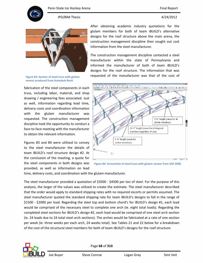
Penn State Ice Hockey Arena Final Report
IPD/BIM Thesis 4/24/2012
Page 68 of 310 Joe Buyer Steve Conroe Logan Gray Simi Veit
After obtaining academic industry quotations for the
glulam members for both of team iBUILD’s alternative
designs for the roof structure above the main arena, the
construction management discipline then sought out cost
information from the steel manufacturer.
The construction management discipline contacted a steel
manufacturer within the state of Pennsylvania and
informed the manufacturer of both of team iBUILD’s
designs for the roof structure. The information that was
requested of the manufacturer was that of the cost of
fabrication of the steel components in each
truss, including labor, material, and shop
drawing / engineering fees associated. Just
as well, information regarding lead time,
delivery costs and coordination information
with the glulam manufacturer was
requested. The construction management
discipline took the opportunity to conduct a
face-to-face meeting with the manufacturer
to obtain the relevant information.
Figures 83 and 84 were utilized to convey
to the steel manufacturer the details of
team iBUILD’s roof structure design #2. At
the conclusion of the meeting, a quote for
the steel components in both designs was
provided, as well as information on lead
time, delivery costs, and coordination with the glulam manufacturer.
The steel manufacturer provided a quotation of $3500 - $4500 per ton of steel. For the purpose of this
analysis, the larger of the values was utilized to create the estimate. The steel manufacturer described
that the order would apply to standard shipping rates with no required escorts or permits assumed. The
steel manufacturer quoted the standard shipping rate for team iBUILD’s designs to fall in the range of
$1500 - $2000 per load. Regarding the steel top and bottom chord’s for iBUILD’s design #1, each load
would be comprised of the necessary steel to complete one arch (ie. eight total loads). Regarding the
completed steel sections for iBUILD’s design #2, each load would be comprised of one steel arch section
(ie. 24 loads due to 24 total steel arch sections). The arches would be fabricated at a rate of one section
per week (ie. three weeks per each arch, 24 weeks total). See Tables 21 and 22 below for a breakdown
of the cost of the structural steel members for both of team iBUILD’s designs for the roof structure:
Figure 83: Section of steel truss with glulam veneer produced from Autodesk Revit
Figure 84: Screenshot of steel truss with glulam veneer from SAP 2000
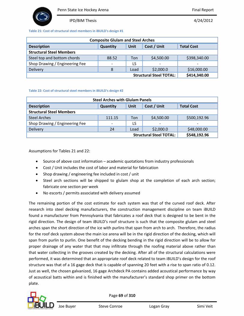
Penn State Ice Hockey Arena Final Report
IPD/BIM Thesis 4/24/2012
Page 69 of 310 Joe Buyer Steve Conroe Logan Gray Simi Veit
Table 21: Cost of structural steel members in iBUILD's design #1
Composite Glulam and Steel Arches
Description Quantity Unit Cost / Unit Total Cost
Structural Steel Members
Steel top and bottom chords 88.52 Ton $4,500.00 $398,340.00
Shop Drawing / Engineering Fee - LS - -
Delivery 8 Load $2,000.0 $16,000.00
Structural Steel TOTAL: $414,340.00
Table 22: Cost of structural steel members in iBUILD's design #2
Steel Arches with Glulam Panels
Description Quantity Unit Cost / Unit Total Cost
Structural Steel Members
Steel Arches 111.15 Ton $4,500.00 $500,192.96
Shop Drawing / Engineering Fee - LS - -
Delivery 24 Load $2,000.0 $48,000.00
Structural Steel TOTAL: $548,192.96
Assumptions for Tables 21 and 22:
Source of above cost information – academic quotations from industry professionals
Cost / Unit includes the cost of labor and material for fabrication
Shop drawing / engineering fee included in cost / unit
Steel arch sections will be shipped to glulam shop at the completion of each arch section;
fabricate one section per week
No escorts / permits associated with delivery assumed
The remaining portion of the cost estimate for each system was that of the curved roof deck. After
research into steel decking manufacturers, the construction management discipline on team iBUILD
found a manufacturer from Pennsylvania that fabricates a roof deck that is designed to be bent in the
rigid direction. The design of team iBUILD’s roof structure is such that the composite glulam and steel
arches span the short direction of the ice with purlins that span from arch to arch. Therefore, the radius
for the roof deck system above the main ice arena will be in the rigid direction of the decking, which will
span from purlin to purlin. One benefit of the decking bending in the rigid direction will be to allow for
proper drainage of any water that that may infiltrate through the roofing material above rather than
that water collecting in the grooves created by the decking. After all of the structural calculations were
performed, it was determined that an appropriate roof deck related to team iBUILD’s design for the roof
structure was that of a 16 gage deck that is capable of spanning 20 feet with a rise to span ratio of 0.12.
Just as well, the chosen galvanized, 16 gage Archdeck PA contains added acoustical performance by way
of acoustical batts within and is finished with the manufacturer’s standard shop primer on the bottom
plate.
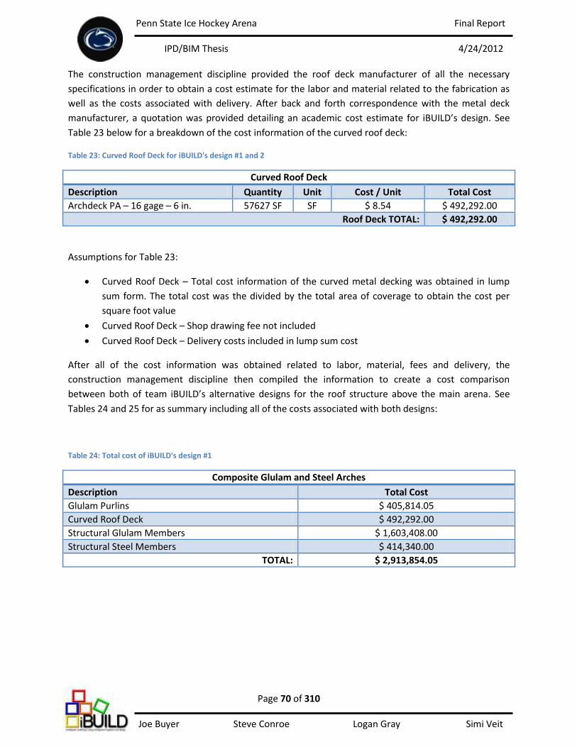
Penn State Ice Hockey Arena Final Report
IPD/BIM Thesis 4/24/2012
Page 70 of 310 Joe Buyer Steve Conroe Logan Gray Simi Veit
The construction management discipline provided the roof deck manufacturer of all the necessary
specifications in order to obtain a cost estimate for the labor and material related to the fabrication as
well as the costs associated with delivery. After back and forth correspondence with the metal deck
manufacturer, a quotation was provided detailing an academic cost estimate for iBUILD’s design. See
Table 23 below for a breakdown of the cost information of the curved roof deck:
Table 23: Curved Roof Deck for iBUILD's design #1 and 2
Curved Roof Deck
Description Quantity Unit Cost / Unit Total Cost
Archdeck PA – 16 gage – 6 in. 57627 SF SF $ 8.54 $ 492,292.00
Roof Deck TOTAL: $ 492,292.00
Assumptions for Table 23:
Curved Roof Deck – Total cost information of the curved metal decking was obtained in lump
sum form. The total cost was the divided by the total area of coverage to obtain the cost per
square foot value
Curved Roof Deck – Shop drawing fee not included
Curved Roof Deck – Delivery costs included in lump sum cost
After all of the cost information was obtained related to labor, material, fees and delivery, the
construction management discipline then compiled the information to create a cost comparison
between both of team iBUILD’s alternative designs for the roof structure above the main arena. See
Tables 24 and 25 for as summary including all of the costs associated with both designs:
Table 24: Total cost of iBUILD's design #1
Composite Glulam and Steel Arches
Description Total Cost
Glulam Purlins $ 405,814.05
Curved Roof Deck $ 492,292.00
Structural Glulam Members $ 1,603,408.00
Structural Steel Members $ 414,340.00
TOTAL: $ 2,913,854.05
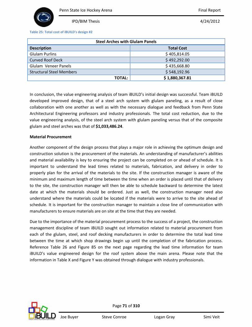
Penn State Ice Hockey Arena Final Report
IPD/BIM Thesis 4/24/2012
Page 71 of 310 Joe Buyer Steve Conroe Logan Gray Simi Veit
Table 25: Total cost of iBUILD's design #2
In conclusion, the value engineering analysis of team iBUILD’s initial design was successful. Team iBUILD
developed improved design, that of a steel arch system with glulam paneling, as a result of close
collaboration with one another as well as with the necessary dialogue and feedback from Penn State
Architectural Engineering professors and industry professionals. The total cost reduction, due to the
value engineering analysis, of the steel arch system with glulam paneling versus that of the composite
glulam and steel arches was that of $1,033,486.24.
Material Procurement
Another component of the design process that plays a major role in achieving the optimum design and
construction solution is the procurement of the materials. An understanding of manufacturer’s abilities
and material availability is key to ensuring the project can be completed on or ahead of schedule. It is
important to understand the lead times related to materials, fabrication, and delivery in order to
properly plan for the arrival of the materials to the site. If the construction manager is aware of the
minimum and maximum length of time between the time when an order is placed until that of delivery
to the site, the construction manager will then be able to schedule backward to determine the latest
date at which the materials should be ordered. Just as well, the construction manager need also
understand where the materials could be located if the materials were to arrive to the site ahead of
schedule. It is important for the construction manager to maintain a close line of communication with
manufacturers to ensure materials are on site at the time that they are needed.
Due to the importance of the material procurement process to the success of a project, the construction
management discipline of team iBUILD sought out information related to material procurement from
each of the glulam, steel, and roof decking manufacturers in order to determine the total lead time
between the time at which shop drawings begin up until the completion of the fabrication process.
Reference Table 26 and Figure 85 on the next page regarding the lead time information for team
iBUILD’s value engineered design for the roof system above the main arena. Please note that the
information in Table X and Figure Y was obtained through dialogue with industry professionals.
Steel Arches with Glulam Panels
Description Total Cost
Glulam Purlins $ 405,814.05
Curved Roof Deck $ 492,292.00
Glulam Veneer Panels $ 435,668.80
Structural Steel Members $ 548,192.96
TOTAL: $ 1,880,367.81
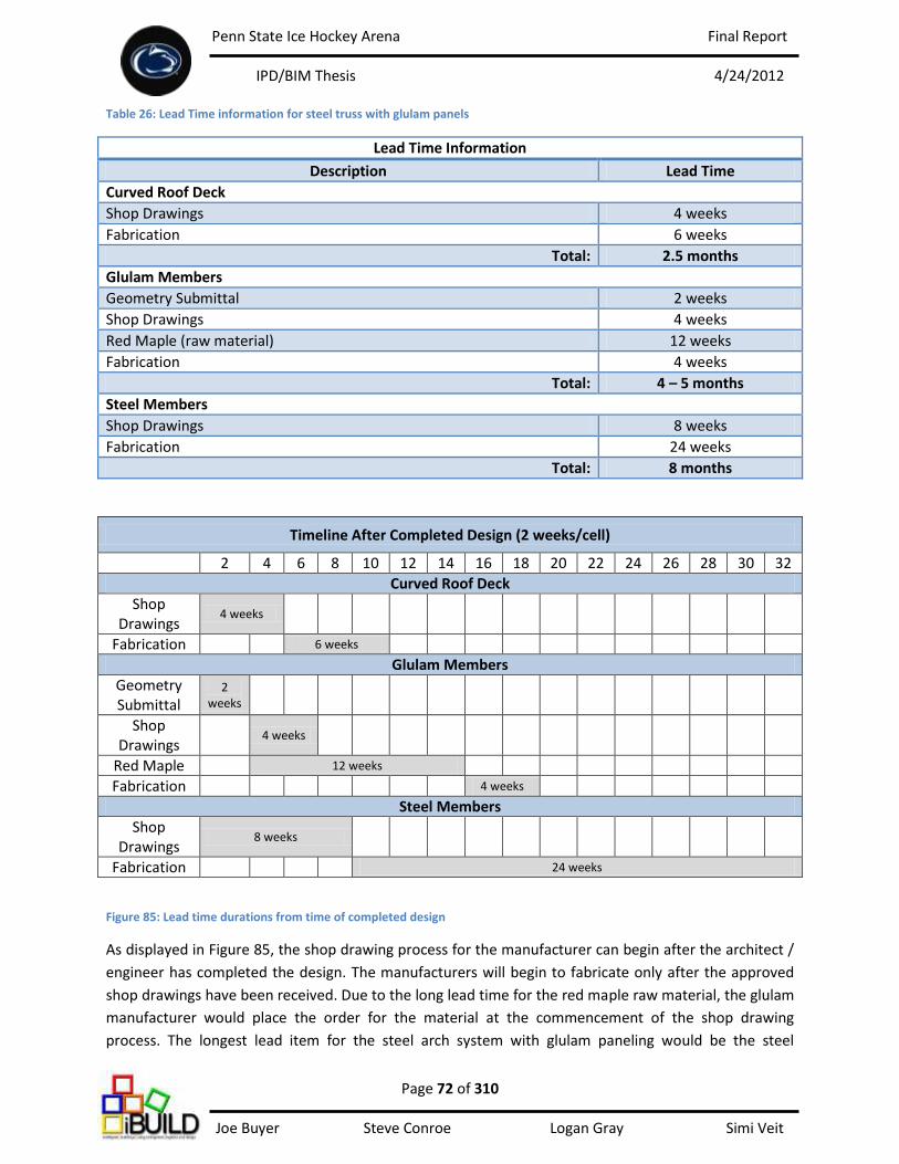
Penn State Ice Hockey Arena Final Report
IPD/BIM Thesis 4/24/2012
Page 72 of 310 Joe Buyer Steve Conroe Logan Gray Simi Veit
Table 26: Lead Time information for steel truss with glulam panels
Lead Time Information
Description Lead Time
Curved Roof Deck
Shop Drawings 4 weeks
Fabrication 6 weeks
Total: 2.5 months
Glulam Members
Geometry Submittal 2 weeks
Shop Drawings 4 weeks
Red Maple (raw material) 12 weeks
Fabrication 4 weeks
Total: 4 – 5 months
Steel Members
Shop Drawings 8 weeks
Fabrication 24 weeks
Total: 8 months
Timeline After Completed Design (2 weeks/cell)
2 4 6 8 10 12 14 16 18 20 22 24 26 28 30 32
Curved Roof Deck
Shop Drawings
4 weeks
Fabrication 6 weeks
Glulam Members
Geometry Submittal
2 weeks
Shop Drawings
4 weeks
Red Maple 12 weeks
Fabrication 4 weeks
Steel Members
Shop Drawings
8 weeks
Fabrication 24 weeks
Figure 85: Lead time durations from time of completed design
As displayed in Figure 85, the shop drawing process for the manufacturer can begin after the architect /
engineer has completed the design. The manufacturers will begin to fabricate only after the approved
shop drawings have been received. Due to the long lead time for the red maple raw material, the glulam
manufacturer would place the order for the material at the commencement of the shop drawing
process. The longest lead item for the steel arch system with glulam paneling would be the steel
Penn State Ice Hockey Arena Final Report
IPD/BIM Thesis 4/24/2012
Page 73 of 310 Joe Buyer Steve Conroe Logan Gray Simi Veit
members. According to the steel manufacturer, a conservative estimate for the fabrication time for each
steel arch section would be that of one section per week. After discussing the fabrication process with
both the steel and glulam manufacturers, it was determined that the best method of fabricating one
complete section of steel arch with glulam paneling would be as follows. At the completion of the
fabrication of each steel arch section, the section would be delivered to the glulam shop for the
installation of the glulam paneling. This was deemed the best solution for this custom arch system. The
steel manufacturer would not want to be held liable for any damages done to the glulam if this process
were reversed. It was deemed most appropriate to deliver the steel sections to the glulam manufacturer
upon fabrication, and then install the glulam paneling to the steel. The glulam manufacturer has the
expertise and experience on handling and maintaining the quality of the glulam members, which will
serve as the exterior finish to the completed arch system from within the arena. The glulam
manufacturer also has the experience and expertise to properly package and prepare the completed
arch sections for delivery to the site to prevent damage.
Please note that the primary purpose of Figure 85 is to display the lead times of each item rather than
serve as a schedule for the procurement process. This information would then be utilized to back-track
to determine the appropriate date to begin communication with the fabricators.
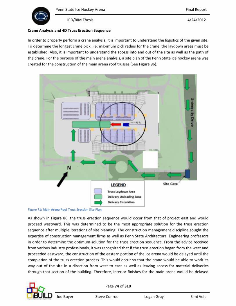
Penn State Ice Hockey Arena Final Report
IPD/BIM Thesis 4/24/2012
Page 74 of 310 Joe Buyer Steve Conroe Logan Gray Simi Veit
Crane Analysis and 4D Truss Erection Sequence
In order to properly perform a crane analysis, it is important to understand the logistics of the given site.
To determine the longest crane pick, i.e. maximum pick radius for the crane, the laydown areas must be
established. Also, it is important to understand the access into and out of the site as well as the path of
the crane. For the purpose of the main arena analysis, a site plan of the Penn State ice hockey arena was
created for the construction of the main arena roof trusses (See Figure 86).
Figure 71: Main Arena Roof Truss Erection Site Plan
As shown in Figure 86, the truss erection sequence would occur from that of project east and would
proceed westward. This was determined to be the most appropriate solution for the truss erection
sequence after multiple iterations of site planning. The construction management discipline sought the
expertise of construction management firms as well as Penn State Architectural Engineering professors
in order to determine the optimum solution for the truss erection sequence. From the advice received
from various industry professionals, it was recognized that if the truss erection began from the west and
proceeded eastward, the construction of the eastern portion of the ice arena would be delayed until the
completion of the truss erection process. This would occur so that the crane would be able to work its
way out of the site in a direction from west to east as well as leaving access for material deliveries
through that section of the building. Therefore, interior finishes for the main arena would be delayed
Penn State Ice Hockey Arena Final Report
IPD/BIM Thesis 4/24/2012
Page 75 of 310 Joe Buyer Steve Conroe Logan Gray Simi Veit
until the structure and east façade were completed. It was determined that by proceeding from east to
west, construction of the eastern structure and façade could occur before or during the main arena truss
erection sequence. This method would not inhibit on the construction of the east façade and the
interior finishes would then have the ability to commence upon the completion of the main arena roof
structure. One possible disadvantage of the truss erection sequence proceeding from east to west is
that a portion of the community rink structure at the south side of the site would need to be left
incomplete to allow for the removal of the crane as well as material deliveries.
The site plan displayed in Figure 86 is a top-down screenshot of the site from Autodesk Navisworks.
Navisworks served as a primary tool for site planning for the construction management discipline
because it allowed for visualization of spatial limitations. The structural and mechanical models of the
main arena were imported into Navisworks, thus providing the construction management discipline with
a scaled model for site planning. The truss sections could be placed on the ground within the model and
show the amount of space required for the laydown areas. The location of the shoring towers and the
crane could also be displayed. After multiple iterations, appropriate laydown areas could be established
on the north and south sides of the crane path. The crane would move in the direction of the red arrow
(east to west) and deliveries would occur from the south side of the site and could be unloaded via the
crane from the west. Access to the site would be from the site gate at the southeast. Utilizing the
measurement capabilities within Navisworks, it was determined that the maximum radius that would be
necessary to perform the longest pick would be that of approximately 70 feet. The crane would lift the
arch sections into place from one location until one complete arch was erected. After which, the crane
would move to its next location, keeping the same distance of 70 feet away to complete the next arch.
When choosing a crane type to perform the erection of the main arena roof structure, there are many
factors to consider. Such factors include: lifting capacities, crane speed capacities, operator visibility, the
transport costs associated with moving the crane onto and off the site, travel lanes, placement of the
crane on the site, critical lifts based on distance and weight, the location of laydown areas, the crane
foundation and many more.
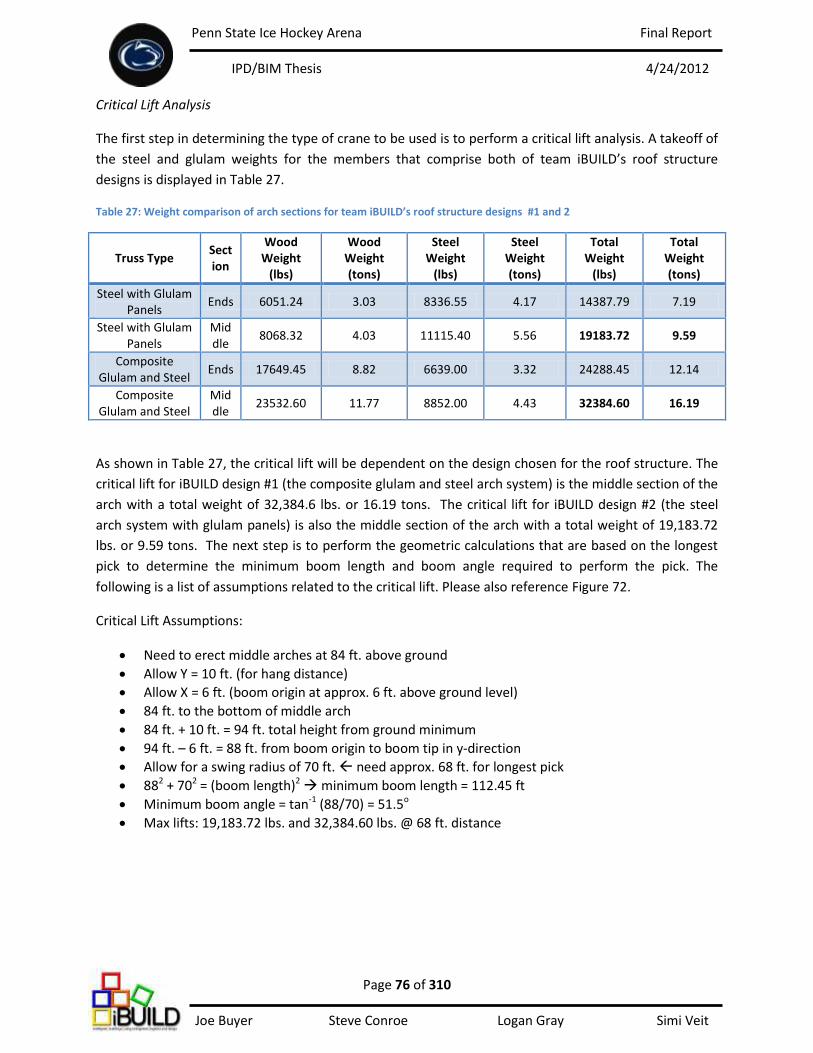
Penn State Ice Hockey Arena Final Report
IPD/BIM Thesis 4/24/2012
Page 76 of 310 Joe Buyer Steve Conroe Logan Gray Simi Veit
Critical Lift Analysis
The first step in determining the type of crane to be used is to perform a critical lift analysis. A takeoff of
the steel and glulam weights for the members that comprise both of team iBUILD’s roof structure
designs is displayed in Table 27.
Table 27: Weight comparison of arch sections for team iBUILD’s roof structure designs #1 and 2
Truss Type Section
Wood Weight
(lbs)
Wood Weight (tons)
Steel Weight
(lbs)
Steel Weight (tons)
Total Weight
(lbs)
Total Weight (tons)
Steel with Glulam Panels
Ends 6051.24 3.03 8336.55 4.17 14387.79 7.19
Steel with Glulam Panels
Middle
8068.32 4.03 11115.40 5.56 19183.72 9.59
Composite Glulam and Steel
Ends 17649.45 8.82 6639.00 3.32 24288.45 12.14
Composite Glulam and Steel
Middle
23532.60 11.77 8852.00 4.43 32384.60 16.19
As shown in Table 27, the critical lift will be dependent on the design chosen for the roof structure. The
critical lift for iBUILD design #1 (the composite glulam and steel arch system) is the middle section of the
arch with a total weight of 32,384.6 lbs. or 16.19 tons. The critical lift for iBUILD design #2 (the steel
arch system with glulam panels) is also the middle section of the arch with a total weight of 19,183.72
lbs. or 9.59 tons. The next step is to perform the geometric calculations that are based on the longest
pick to determine the minimum boom length and boom angle required to perform the pick. The
following is a list of assumptions related to the critical lift. Please also reference Figure 72.
Critical Lift Assumptions:
Need to erect middle arches at 84 ft. above ground
Allow Y = 10 ft. (for hang distance)
Allow X = 6 ft. (boom origin at approx. 6 ft. above ground level)
84 ft. to the bottom of middle arch
84 ft. + 10 ft. = 94 ft. total height from ground minimum
94 ft. – 6 ft. = 88 ft. from boom origin to boom tip in y-direction
Allow for a swing radius of 70 ft. need approx. 68 ft. for longest pick
882 + 702 = (boom length)2 minimum boom length = 112.45 ft
Minimum boom angle = tan-1 (88/70) = 51.5o
Max lifts: 19,183.72 lbs. and 32,384.60 lbs. @ 68 ft. distance
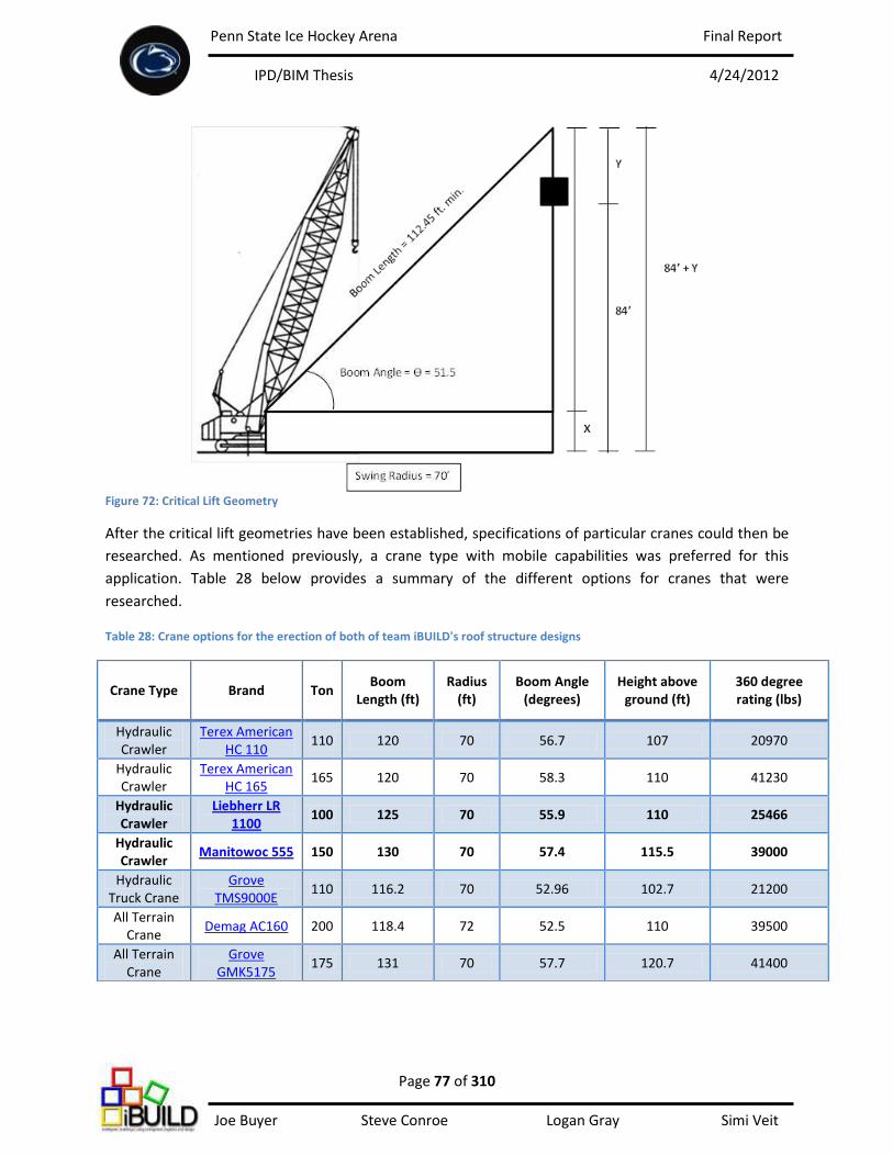
Penn State Ice Hockey Arena Final Report
IPD/BIM Thesis 4/24/2012
Page 77 of 310 Joe Buyer Steve Conroe Logan Gray Simi Veit
Figure 72: Critical Lift Geometry
After the critical lift geometries have been established, specifications of particular cranes could then be
researched. As mentioned previously, a crane type with mobile capabilities was preferred for this
application. Table 28 below provides a summary of the different options for cranes that were
researched.
Table 28: Crane options for the erection of both of team iBUILD's roof structure designs
Crane Type Brand Ton Boom
Length (ft) Radius
(ft) Boom Angle
(degrees) Height above
ground (ft) 360 degree rating (lbs)
Hydraulic Crawler
Terex American HC 110
110 120 70 56.7 107 20970
Hydraulic Crawler
Terex American HC 165
165 120 70 58.3 110 41230
Hydraulic Crawler
Liebherr LR 1100
100 125 70 55.9 110 25466
Hydraulic Crawler
Manitowoc 555 150 130 70 57.4 115.5 39000
Hydraulic Truck Crane
Grove TMS9000E
110 116.2 70 52.96 102.7 21200
All Terrain Crane
Demag AC160 200 118.4 72 52.5 110 39500
All Terrain Crane
Grove GMK5175
175 131 70 57.7 120.7 41400
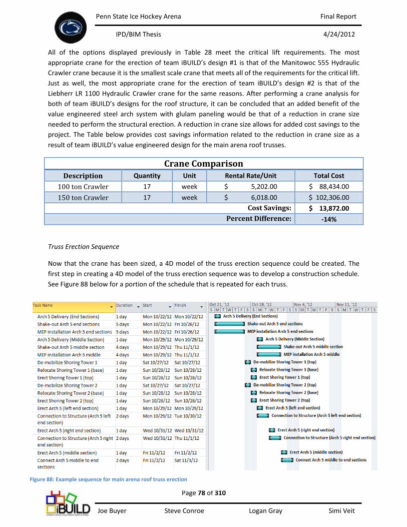
Penn State Ice Hockey Arena Final Report
IPD/BIM Thesis 4/24/2012
Page 78 of 310 Joe Buyer Steve Conroe Logan Gray Simi Veit
All of the options displayed previously in Table 28 meet the critical lift requirements. The most
appropriate crane for the erection of team iBUILD’s design #1 is that of the Manitowoc 555 Hydraulic
Crawler crane because it is the smallest scale crane that meets all of the requirements for the critical lift.
Just as well, the most appropriate crane for the erection of team iBUILD’s design #2 is that of the
Liebherr LR 1100 Hydraulic Crawler crane for the same reasons. After performing a crane analysis for
both of team iBUILD’s designs for the roof structure, it can be concluded that an added benefit of the
value engineered steel arch system with glulam paneling would be that of a reduction in crane size
needed to perform the structural erection. A reduction in crane size allows for added cost savings to the
project. The Table below provides cost savings information related to the reduction in crane size as a
result of team iBUILD’s value engineered design for the main arena roof trusses.
Crane Comparison
Description Quantity Unit Rental Rate/Unit Total Cost
100 ton Crawler 17 week $ 5,202.00 $ 88,434.00
150 ton Crawler 17 week $ 6,018.00 $ 102,306.00
Cost Savings: $ 13,872.00
Percent Difference: -14%
Truss Erection Sequence
Now that the crane has been sized, a 4D model of the truss erection sequence could be created. The
first step in creating a 4D model of the truss erection sequence was to develop a construction schedule.
See Figure 88 below for a portion of the schedule that is repeated for each truss.
Figure 88: Example sequence for main arena roof truss erection
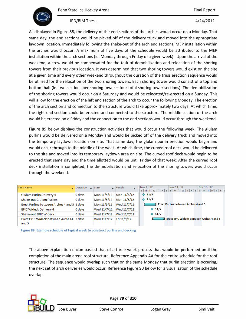
Penn State Ice Hockey Arena Final Report
IPD/BIM Thesis 4/24/2012
Page 79 of 310 Joe Buyer Steve Conroe Logan Gray Simi Veit
As displayed in Figure 88, the delivery of the end sections of the arches would occur on a Monday. That
same day, the end sections would be picked off of the delivery truck and moved into the appropriate
laydown location. Immediately following the shake-out of the arch end sections, MEP installation within
the arches would occur. A maximum of five days of the schedule would be attributed to the MEP
installation within the arch sections (ie. Monday through Friday of a given week). Upon the arrival of the
weekend, a crew would be compensated for the task of demobilization and relocation of the shoring
towers from their previous location. It was determined that two shoring towers would exist on the site
at a given time and every other weekend throughout the duration of the truss erection sequence would
be utilized for the relocation of the two shoring towers. Each shoring tower would consist of a top and
bottom half (ie. two sections per shoring tower – four total shoring tower sections). The demobilization
of the shoring towers would occur on a Saturday and would be relocated/re-erected on a Sunday. This
will allow for the erection of the left end section of the arch to occur the following Monday. The erection
of the arch section and connection to the structure would take approximately two days. At which time,
the right end section could be erected and connected to the structure. The middle section of the arch
would be erected on a Friday and the connection to the end sections would occur through the weekend.
Figure 89 below displays the construction activities that would occur the following week. The glulam
purlins would be delivered on a Monday and would be picked off of the delivery truck and moved into
the temporary laydown location on site. That same day, the glulam purlin erection would begin and
would occur through to the middle of the week. At which time, the curved roof deck would be delivered
to the site and moved into its temporary laydown area on site. The curved roof deck would begin to be
erected that same day and the time allotted would be until Friday of that week. After the curved roof
deck installation is completed, the de-mobilization and relocation of the shoring towers would occur
through the weekend.
The above explanation encompassed that of a three week process that would be performed until the
completion of the main arena roof structure. Reference Appendix AA for the entire schedule for the roof
structure. The sequence would overlap such that on the same Monday that purlin erection is occuring,
the next set of arch deliveries would occur. Reference Figure 90 below for a visualization of the schedule
overlap.
Figure 89: Example schedule of typical week to construct purlins and decking
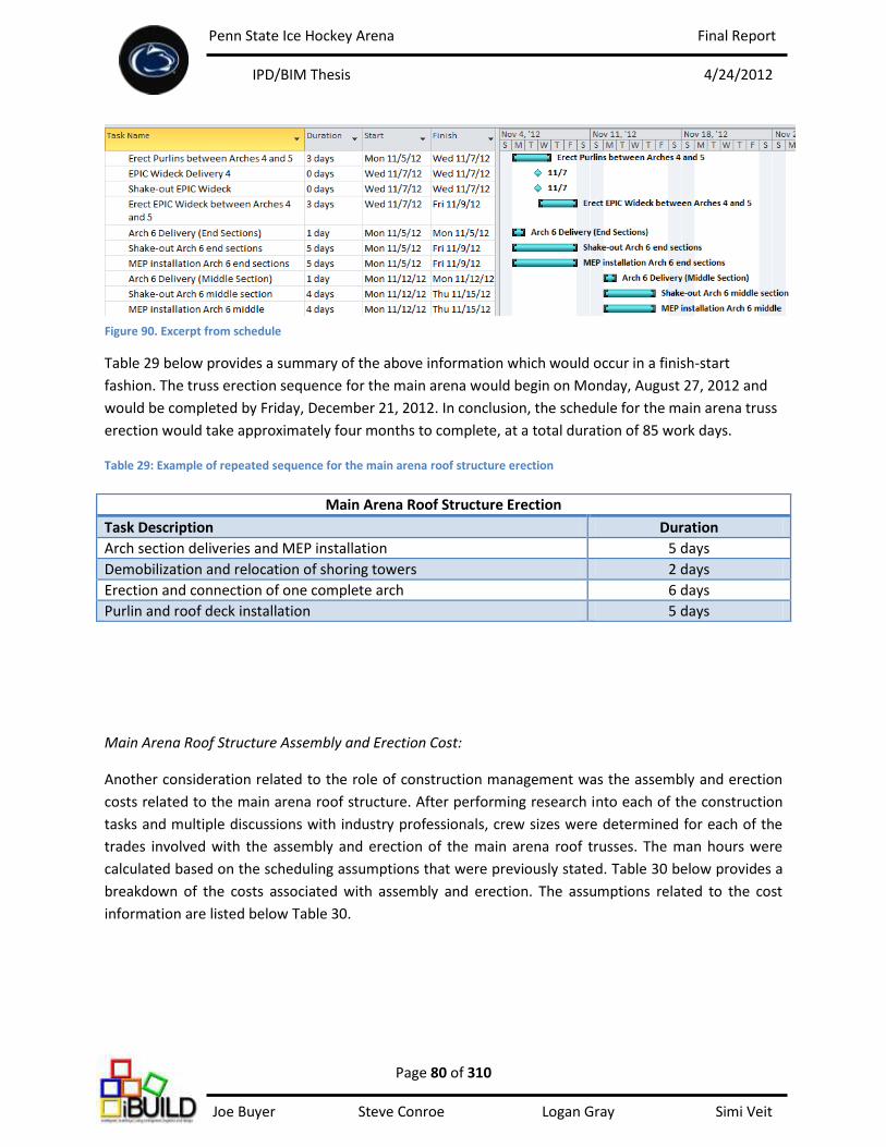
Penn State Ice Hockey Arena Final Report
IPD/BIM Thesis 4/24/2012
Page 80 of 310 Joe Buyer Steve Conroe Logan Gray Simi Veit
Table 29 below provides a summary of the above information which would occur in a finish-start
fashion. The truss erection sequence for the main arena would begin on Monday, August 27, 2012 and
would be completed by Friday, December 21, 2012. In conclusion, the schedule for the main arena truss
erection would take approximately four months to complete, at a total duration of 85 work days.
Table 29: Example of repeated sequence for the main arena roof structure erection
Main Arena Roof Structure Assembly and Erection Cost:
Another consideration related to the role of construction management was the assembly and erection
costs related to the main arena roof structure. After performing research into each of the construction
tasks and multiple discussions with industry professionals, crew sizes were determined for each of the
trades involved with the assembly and erection of the main arena roof trusses. The man hours were
calculated based on the scheduling assumptions that were previously stated. Table 30 below provides a
breakdown of the costs associated with assembly and erection. The assumptions related to the cost
information are listed below Table 30.
Main Arena Roof Structure Erection
Task Description Duration
Arch section deliveries and MEP installation 5 days
Demobilization and relocation of shoring towers 2 days
Erection and connection of one complete arch 6 days
Purlin and roof deck installation 5 days
Figure 90. Excerpt from schedule
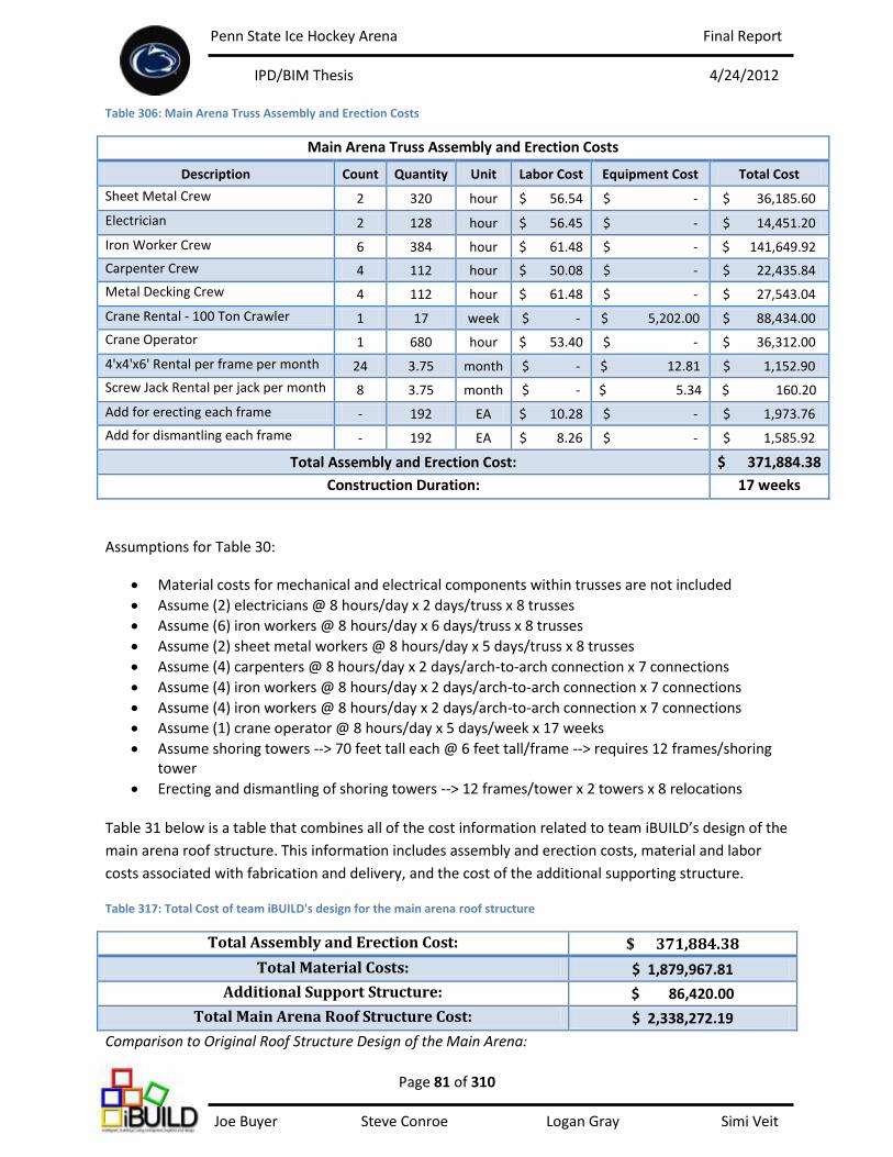
Penn State Ice Hockey Arena Final Report
IPD/BIM Thesis 4/24/2012
Page 81 of 310 Joe Buyer Steve Conroe Logan Gray Simi Veit
Table 306: Main Arena Truss Assembly and Erection Costs
Main Arena Truss Assembly and Erection Costs
Description Count Quantity Unit Labor Cost Equipment Cost Total Cost
Sheet Metal Crew 2 320 hour $ 56.54 $ - $ 36,185.60
Electrician 2 128 hour $ 56.45 $ - $ 14,451.20
Iron Worker Crew 6 384 hour $ 61.48 $ - $ 141,649.92
Carpenter Crew 4 112 hour $ 50.08 $ - $ 22,435.84
Metal Decking Crew 4 112 hour $ 61.48 $ - $ 27,543.04
Crane Rental - 100 Ton Crawler 1 17 week $ - $ 5,202.00 $ 88,434.00
Crane Operator 1 680 hour $ 53.40 $ - $ 36,312.00
4'x4'x6' Rental per frame per month 24 3.75 month $ - $ 12.81 $ 1,152.90
Screw Jack Rental per jack per month 8 3.75 month $ - $ 5.34 $ 160.20
Add for erecting each frame - 192 EA $ 10.28 $ - $ 1,973.76
Add for dismantling each frame - 192 EA $ 8.26 $ - $ 1,585.92
Total Assembly and Erection Cost: $ 371,884.38
Construction Duration: 17 weeks
Assumptions for Table 30:
Material costs for mechanical and electrical components within trusses are not included
Assume (2) electricians @ 8 hours/day x 2 days/truss x 8 trusses
Assume (6) iron workers @ 8 hours/day x 6 days/truss x 8 trusses
Assume (2) sheet metal workers @ 8 hours/day x 5 days/truss x 8 trusses
Assume (4) carpenters @ 8 hours/day x 2 days/arch-to-arch connection x 7 connections
Assume (4) iron workers @ 8 hours/day x 2 days/arch-to-arch connection x 7 connections
Assume (4) iron workers @ 8 hours/day x 2 days/arch-to-arch connection x 7 connections
Assume (1) crane operator @ 8 hours/day x 5 days/week x 17 weeks
Assume shoring towers --> 70 feet tall each @ 6 feet tall/frame --> requires 12 frames/shoring tower
Erecting and dismantling of shoring towers --> 12 frames/tower x 2 towers x 8 relocations
Table 31 below is a table that combines all of the cost information related to team iBUILD’s design of the
main arena roof structure. This information includes assembly and erection costs, material and labor
costs associated with fabrication and delivery, and the cost of the additional supporting structure.
Table 317: Total Cost of team iBUILD's design for the main arena roof structure
Total Assembly and Erection Cost: $ 371,884.38
Total Material Costs: $ 1,879,967.81
Additional Support Structure: $ 86,420.00
Total Main Arena Roof Structure Cost: $ 2,338,272.19
Comparison to Original Roof Structure Design of the Main Arena:

Penn State Ice Hockey Arena Final Report
IPD/BIM Thesis 4/24/2012
Page 82 of 310 Joe Buyer Steve Conroe Logan Gray Simi Veit
Although it was not the goal of team iBUILD to compare to the original design of the roof structure, the
construction management discipline elected to perform a cost comparison of team iBUILD’s roof
structure design of the main arena to that of the original roof structure design detailed in the design
documents. Table 32 below provides a summary of the costs for each design (refer to Appendix U for
the complete estimate and quantity takeoffs).
Table 32: Main Arena Structure Cost Comparison to Original Design
Main Arena Structure Cost Comparison
Original Roof
Structure Steel Arches with Glulam
Panels Cost Difference
Glulam Total - $ 839,482.85 $ (839,482.85)
Roof Deck $ 171,075.78 $ 492,292.00 $ (321,216.22)
Structural Steel Members $ 1,683,600.00 $ 548,192.96 $ 1,135,407.04
Additional Support Structure - $ 86,420.00 $ (86,420.00)
TOTAL: $ 1,854,675.78 $ 1,966,387.81 $ 111,712.03
As displayed in Table 32, team iBUILD’s main arena roof structure has been calculated to cost
$111,712.03 more than that of the original roof structure design for the main arena. Team iBUILD’s end
goal was not to work towards an improvement to the existing design at the time the documents were
provided, but rather to create an original design and value engineer the team’s ideas. This cost
comparison was performed upon request.
Figure 91: View of both the original design (left) and team iBUILD's design (right) of the main arena roof structure
Penn State Ice Hockey Arena Final Report
IPD/BIM Thesis 4/24/2012
Page 83 of 310 Joe Buyer Steve Conroe Logan Gray Simi Veit
Team iBUILD’s Sustainability Efforts
Rather that conducting a comprehensive LEED study for the entire building, team iBUILD decided to
simply make sustainability a driving factor through the design process. This decision was deemed most
appropriate because the team did not conduct analysis on the building as a whole, but rather focused
attention on three of the building spaces. To state differently, rather than performing a LEED analysis
and validating LEED credits to be awarded to the project, the team elected to make efforts towards
sustainability for each of the three spaces that are being analyzed.
Team iBUILD’s sustainability efforts for the main arena analysis primarily focused on selecting regional
building materials. This effort was driven by a number of reasons. By specifying regional materials that
were grown, harvested, and/or manufactured within 500 miles of the project site, transportation costs
as well as harmful emissions being released into the atmosphere as a result of travel, are being kept to a
minimum. Team iBUILD conducted research into a variety of different manufacturers when selecting the
structural materials for the roof truss components. Both the sources for the glulam and structural steel
components of the main arena roof trusses originate within a 500 mile radius. For example, the Red
Maple glulam wood paneling for the trusses is a Pennsylvania hardwood, as well as being Forest
Stewardship Council (FSC) certified. Selecting regional materials for the main arena roof structure design
was the primary sustainability effort of team iBUILD for the main arena analysis.