Embed Size (px)
Citation preview

PendoTECH Filter Screening SystemTM for Normal Flow Filtration Experiments
• Conducts volume throughput studies with constant flow or constant pressure• Four simultaneous filtration optimization studies• Designed for up to 3 filters per train - perfect tool for Virus-Depth Filtration optimization• Process interaction via graphical user interface (GUI) with real-time trending feature• Data acquisition of process data and experiment details• Four independent filter trains each with their own pump control. Designed for up to 3 filters per train - each train with 3 pressure measurements, weight measurement, plus optionally additional process data such as turbidity and temperature• Completely automated with total volume or pressure endpoints and alarms
Product Information
DATA SHEET
www.pendotech.com Tel: +1-609-799-2299 Copyright © 2018 PendoTECH NFFSS-REV6

Product Overview
2
Normal Flow Filtration Processes and Filter Screening Understanding the performance of filtration unit operations when developing a biotech process for clarification of therapeutic agents is an important consideration. Non-optimal filter selection can significantly affect the cost of goods upon scale-up and also impact efficiency and operation of many other unit operations in the bioprocessing train. Therefore adequate process characterization is required with methods and tools to screen and size filters in a cost effective, practical and operationally friendly manner is central to any development function. Small scale filter test devices that contain the same filter media as in the large devices are offered my many of the major filter vendors. These are well suited for screening at the laboratory development scale for sizing and selection to create the optimal scale-up model.
Filter screening can be particularly useful virus filtration steps where there may be a pre-filter followed by a virus filter and also for centrifugation harvest development. The development of a traditional centrifuge process for the removal of cells and cellular debris varies such parameters as cell concentration or PCV, viability, feed flow rate and bowl speed. However, the input operational parameters of the centrifuge process will directly affect the filterability of the resulting centrate.
Measuring filter capacity (as a function of volumetric throughput at constant pressure or constant flow) of the depth and sterile filters down stream as a function of centrifuge operating conditions (bowl speed and flow rate) and filter types is important. Pressure is a critical parameter to measure as an indication of filter performance and capacity. Performing such a multiple factor experiment can produce a large number of conditions depending on the experimental design strategy employed.
Schematic of Clarification Process that can be simulated at laboratory scale
With pressure being a key dependent variable in the experimentation, pressure data measurement is a key feature of any system design. The integration of a pressure sensor to the vent hole or feed line of a screening filter with calibration not required and integrated to a data collection and retrieval system is advantageous.
Important factors to consider when implementing a system for filtration studies are: ability to conduct parallel experiments, data collection, storage and flexible trend analysis.
The PendoTECH Filter Screening System can assist dramatically in the optimization of a normal flow filtration process.
Pressure Sensors
Depth Filter
Pre-Filter
Sterile Filter
ProductionBioreactor
Disk StackCentrifuge
MultipleCentrateStreams
DepthFilter
Screening
SterileFilter
Screening
Fig 1. Process Flow Diagram for Centrifuge and Subsequent Filter Development
www.pendotech.com Tel: +1-609-799-2299

Configuration Options
CONTROL BOX
PC WITH SOFTWARE
PUMPS
PRESSURE SENSORS
SCALES
3
Core System Comprised of:
The Control Box is the “brains” behind the system. Pressure sensors and scales are read by the control box as well as pumps are controlled. In addition, all settings are stored in the memory and while running, endpoints and alarms are monitored here.
The user interaction with the system is via the PC. The PC with the custom Filter Screening System software communicates with the control system: 1) Receiving all data for viewing and storage2) Updating the parameters in the control system via the user interaction with the PC software3) Optionally, the PC running the software can serve the data to OPC clients such as a data historian and PI from OSIsoft®
Any size PendoTECH Pressure Sensor can be used but most often, the sensors with the luer fittings are often the best choice. Features of the luer sensors are: • Low hold-up volume • Polycarbonate version come sterile in its Tyvek pouch • Polysulfone version for superior chemical resistance Sanitary flange sensors are available to connect to filters with flanges
The amount of material that is filtered is measured by the scales integrated to the system. For constant flow applications, the scales function can be disabled and the filtered volume will automatically be measured by pump totalization based on the flow rate setting.
For constant pressure applications, the scales are required to measure the cumulative volume versus time. Also, for ‘constant pressure’ (ie, Vmax) experiments, a pressure vessel is required. PendoTECH offers one option with a low hold-up volume, precise pressure regulation and pressure recording capability.
Pumps are a critical component of any integrated system used for ‘constant flow’ experiments (ie, Pmax) . Two specially designed pump modules are available from PendoTECH - one is a Peristaltic Pump Module and the other a Diaphragm Pump Module. They offer different characteristics and are both packaged in a compact form factor to minimize bench space required for a full featured set-up. The Diaphragm Pump Module enables generation of pressure up to 60 psi/4 bar. In addtion, 3rd party pumps can be used such as pumps offered by Masterflex and Watson-Marlow. These may enable a more flexible setup as pumps can be used for other purposes when not in use with the system.
PendoTECH Peristaltic Pump Module
Watson-Marlow 120 PumpMasterflex L/S Pump
OhausMettler-Toledo
Pressure sensor with luer fitting
inlet/outlet
Copyright © 2018 PendoTECH NFFSS-REV6
PendoTECH Diaphragm Pump Module
Sartorious
Pressure sensor with sanitary flange

Key Features
4
• Operate up to 4 trains in parallel with up to 3 pressure measurements per train• Graphical User Interface (GUI) to streamline user interaction with the process• Interfaces with up to 4 pumps for independent control of each pump• Automation allows the system to be operated unattended - individual pumps will shut off when volume target is reached or alarm occurs• Total flow by either scales with ability to enter density to convert weight to volume or pump accumulation (eliminates need for scale and filtered volume is estimated)• Alarms for high pressure for each train and high delta pressures for each filter that will shut the pump off for that train• Real time calculation of flux and permeability based on entered filter area within GUI• Ability to view a wide variety of trends real-time with instant export feature of current trend view• Process data acquisition (including filter, train names and key experiment information and notes) into a CSV data file that is opened with Excel• Ability to run four parallel Constant Pressure experiments by use of scale input functionality • PendoTECH Pressure Sensors with luer fittings connect directly to filter test devices or larger sensors with sanitary flange or barb can be used • Expansion option for input of up to 2 analytical measurements per train such as temperature and turbidity.• Logs individual pump run times for management of pump maintenance and/or tubing change outs• FLOW-ADJUST Feature where GUI automatically controls a filter deltaP Setpoint• Option to serve data to OPC clients such as PI from OSIsoft®
1 - Setup - enter filter information, alarm settings and volume endpoint 2 - System View - view process data, change flow rate, start/stop pumps3 - Trends View - create trends and view process data over time 4 - Communication - start data file and save/recall setup information and setup optional inputs5 - Maintenance View - zero pressure sensors, zero total volume, setup pumps and reset the run-time counter6 - Constant Pressure Tab - for viewing data and performing calculations during constant pressure experiments
System View
When the pump is running, the indicator is rotating, if there is an alarm, the pump
will turn red and the type of alarm will appear under the pump
If spare analog inputs are enabled, external
devices (ie, turbidity meter) with a transmitter function can be quickly
configured in the system software and values will be displayed here and also
written to the data file with other process data
For each train, shown is the actual pressure, differential pressure, and
max differential pressure
The max value on the gauge is
set by the train max pressure limit (entered on set-up tab)
The scale displays percentage
of volume target achieved
This is the “dashboard” for constant flow experiments where all process data can be viewed. In addition pumps can be stopped/started and flow rates adjusted.
6 Tabs for Fast and Easy Navigation (System View Shown)
www.pendotech.com Tel: +1-609-799-2299
New flow rate can be
entered here
Run/Stop buttons and
when running only Stop is highlighted
Volume target entered on Setup is
shown along with target valve

5
Setup View
Information is written to header of data file when data collection
is started; then it becomes uneditable
Critical information for each train
is entered here. Filter area is used for calculated values.
FLOW-ADJUST FEATURE
for pressure control is enabled and additional settings appear
Ability to change the pump flow manually is disabled
on System View
Volumetric endpoint
is entered and pumps automatically stop when
this point is reached
The Setup view is where end points and alarm points are entered, along with information critical to an experiment such as train names, filter names and areas. Train names and filter names are all stored in the data file as a permanent record. In addition electronic notes can be entered during an experiment that are time-stamped when entered in the file. These notes are excellent for observations or to mark sample points. The FLOW-ADJUST feature can be activated which allows the pump flow to be automatically reduced to maintain pressure.
Delta P setpoints are entered here
Notes - Click here and a pop-up box appears where an electronic note can be entered. The note is
written to the data file one time and time-stamped.
Copyright © 2018 PendoTECH NFFSS-REV6
User Interface Details
Unlimited number of set-ups can be saved
for recall later

6
Pressure Sensors
Trains
Filters
Trends View
List of choices based on
trends selected (shown with pressure
selected)
Slide to change cursor value
Options to select Auto-scale or Manual scale on all axes
simply by clicking axis
After data collection is initiated by the user, real-time trending is active.• Select up to 8 trends simultaneously (can be changed as needed)• Export the trended data direct to a file• Export plot image• Open selected data directly in Excel for quick-calculations
Separately from the trending, data is written to the file created when data collection is started and the frequency is set on the communication tab which can be different than the trending frequency. The data is written to the locked file until the user “ends data collection,” and the file is released. All data and notes are logged. Train 1 data is shown below and there are additional columns for Trains 2 to 4.
Data Storage
Drop down list of
parameters to trend Export the current trend only
to open in software such as Excel
Ability to change plot update rate
Quickly compare current values to
cursor value
Powerful tools to zoom, export an image of the current trend
and much more
Trending Data & Data Storage
www.pendotech.com Tel: +1-609-799-2299
7
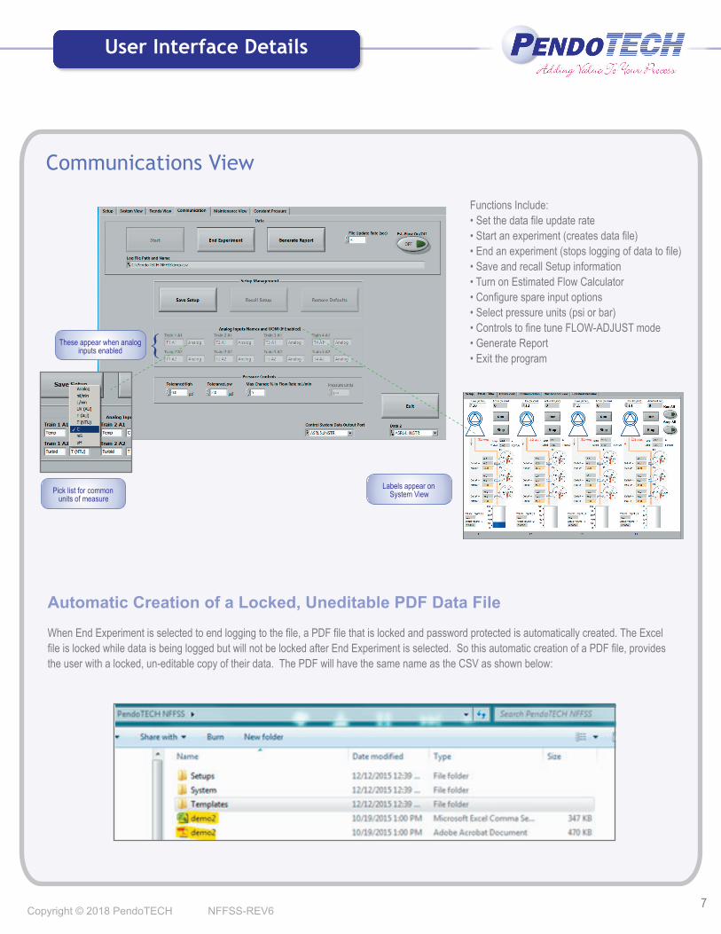
Functions Include:• Set the data file update rate • Start an experiment (creates data file) • End an experiment (stops logging of data to file)• Save and recall Setup information• Turn on Estimated Flow Calculator • Configure spare input options• Select pressure units (psi or bar) • Controls to fine tune FLOW-ADJUST mode• Generate Report • Exit the program
Communications View
Pick list for common
units of measure
{ These appear when analog
inputs enabled
Labels appear on
System View
Copyright © 2018 PendoTECH NFFSS-REV6
User Interface Details
Automatic Creation of a Locked, Uneditable PDF Data File
When End Experiment is selected to end logging to the file, a PDF file that is locked and password protected is automatically created. The Excel file is locked while data is being logged but will not be locked after End Experiment is selected. So this automatic creation of a PDF file, provides the user with a locked, un-editable copy of their data. The PDF will have the same name as the CSV as shown below:
User Interface Details
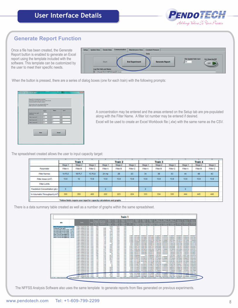
Generate Report Function
Once a file has been created, the Generate Report button is enabled to generate an Excel report using the template included with the software. This template can be customized by the user to meet their specific needs.
A concentration may be entered and the areas entered on the Setup tab are pre-populated along with the Filter Name. A filter lot number may be entered if desired.Excel will be used to create an Excel Workbook file (.xlw) with the same name as the CSV.
There is a data summary table created as well as a number of graphs within the same spreadsheet.
When the button is pressed, there are a series of dialog boxes (one for each train) with the following prompts:
The NFFSS Analysis Software also uses the same template to generate reports from files generated on previous experiments.
www.pendotech.com Tel: +1-609-799-2299 8
The spreadsheet created allows the user to input capacity target:

Maintenance View
• Tare pressure sensors• Zero flow totalizer or tare scales• Configure pumps• Monitor pump run time - may be reset with password
Pumps are quickly configured here based on the pump used
Quick-picks for commonchoices or the ability to
set each one manually soany pump can be accommodated
Displays pump run time to monitor
tubing life so it can be replaced at set intervals or maintenance cycles on
the diaphragm pump. A password is required to reset this to zero
User Interface Details
Tubing Size ID (in) 1/32 1/16 1/8 3/16
Tubing Size OD (in) 5/32 3/16 1/4 5/16 Tubing Size ID (mm) 0.8mm 1.6mm 3.2mm 4.8mm
Masterflex L/S reference 13 14 16 25 Max Flow (mL/min) 8.0 28 94 170
mL/rotation 0.04 0.14 0.47 0.85Max RPMs = 200
Max RPMs = 600Copyright © 2018 PendoTECH NFFSS-REV6 9
Pump Calibration
Tubing Size ID (in) 1/32 1/16 1/8 3/16
Tubing Size OD (in) 5/32 3/16 1/4 5/16 Masterflex L/S 13 14 16 25 Max Flow (mL/min) 36 130 480 1000
mL/rotation 0.06 0.22 0.8 1.7
Masterflex L/S Pump
Watson-Marlow 120 Pump
The Pump Selector drop-down box has a range of choices for nominal pump calibrations. There are two factors used to calibrate any pump- one is its maximum motor speed in RPMs; the other is how much liquid is delivered each time the motor turns and this is quantified in mL/rotation. When these two values are multiplied, you get a maximum flow rate possible. In a peristaltic pump, the mL/rotation is based on the tubing inner diameter; and for a diaphragm pump, the mL/rotation is based on the pump chamber. For fine-tuning calibration or for configuration of a pump/tubing combination not in the list, there is an option called Custom Settings where individual values can be entered for Maximum RPMs and mL/rot. For more details on pump calibration, please view he PendoTECH Pump Calibration Tech Note.

Constant Pressure Filtration
10
Constant Pressure/VmaxTM
PendoTECH Pressure Vessel with Regulated Pressure Source
A pressure vessel with a precision regulated pressure source can be used to conduct 4 simultaneous “Vmax” experiments.
The software creates two concurrent trends of volume vs. clock time and elapsed time vs. elapsed time/volume. This allows the view of a direct plot of rate of volume accumulation and the plot of predictive model calculations. Using the calculations associated with this predictive method, the correlation coefficient is calculated real-time to confirm if the prediction model is valid and the predicted max throughout is calculated real-time. This is normalized to L/m2 using Filter A area.
Estimated flow value is based on a regression of volume and
time, also displays estimated flux
These calculations are based on a linear regression
of data sets of elapsed time and elapsed time/Volume that populate an array at the frequency set as the
Update Rate
Two separate graphs on the same plot area - one is t/V versus elapsed t and
other is V versus clock time
Choices are 30s or 60s
Ability to export time and volume so data can be easily dropped into user templates of existing
models
When Run All is clicked the
calculations start
Vessel top with pressure sensor
connected for data logging
Polysulfone vessel with
graduation marks
Clamps for quick assembly/
disassembly of vessel for cleaning
Vessel bottom with
2-way stopcock
Precision regulator
Air source
shut-off valve
Male luer for 3-way
stop cock. Use top portFor vent and side to connect
pressure sensor to record pressure
Safety Valve set to 45 psi (to prevent over-
pressure situation)
Quick connect for Air inlet
from Regulator
Top Detail
Bottom Detail
316 Stainless steel bottomwith integral luer fitting for
attachment of filter and valve
www.pendotech.com Tel: +1-609-799-2299
Scale

11
Control System Back Panel Input/Output Connections
The system comes with the required cables to enable the system to be quickly up and running. All connections are keyed to prevent connection of a cable to the wrong connector. Pumps and scales may be delivered with the system or existing equipment or self-procured equipment may be used. A scale selection menu on the process control system is used to quickly configure the RS232 parameters for the different scale brands. The pump cables are supplied to interface to the remote control connector on the user selected pumps as shown in the example below.
Example of Pump Back Panel with remote interface connector
Interface Connector
PendoTECH Single Use Pressure Sensors
Pressure Sensor Cable
Pump Cable for 4 pumps (Masterflex Pump Cable Shown)
Control SystemPumps
Scales
Pressure sensor cables provided with the system accept the PendoTECH Single Use Pressure Sensors (see below). Even though these are called single use, they are robust enough to be re-used for process development work where cross-contamination is not a concern.
Most scales have RS232 communication built-in and a cable either integral or available separately to connect to the system
PC Requirements:Windows 7 or 10, 2 GHz or faster, 4GB of RAM with at least 2 available USB ports
Pressure Sensors
Pumps
PC
Connects to System
Copyright © 2018 PendoTECH NFFSS-REV6
Components Interfaced to Control System
Pump Module

Pump Options
12
2) PendoTECH Peristaltic Pump Module
Product Features• Peristaltic design with easily changeable fluid path that uses commonly available tubing• Minimal drop in flow while pumping against back pressure• Stepper motor control technology that pumps precisely• Space-saving design with quiet operation• Precise pumping from 1 mL/min to 120 mL/min• May be run dry
1) PendoTECH Diaphragm Pump Module
• Low shear, long life diaphragm pump technology• Minimal drop in flow while pumping against back pressure• Stepper motor control “Rapid Intake” stroke technology that minimizes pulsation• Space-saving design with quiet operation• Precise pumping from 2.0 mL/min to 100 mL/min• Low internal hold-up volume• Broad range of chemical compatibility (product contacting internal pump components are all fluoropolymer based)• May be run dry
Product Features
3) Third Party Pumps
Pumps from popular manufacturers like Masterflex and Watson-Marlow may already be owned and if it has the interface connector on the back panel, it can be used. Also, these pumps may be purchased directly from PendoTECH with the system. These pumps offer flexibility to use a wide range of tubing sizes and also may be used for other lab applications when not interfaced with the system
Masterflex L/S Watson Marlow 120UUses the full range of L/S tubing sizes for wide flow range capability
4 Pumps Required - Each is controlled independently by the system
4 Pumps Required - Each is controlled independently by the system
Compact design minimizes bench space required
www.pendotech.com Tel: +1-609-799-2299

13
Filter Screening System Peristaltic Pump ModuleThe Peristaltic Pump Module is an accessory for the PendoTECH Filter Screening System. The module can only be operated by interface with the system and is not designed to be operated independently. The pumps in the module are compact peristaltic pumps that are controlled from the Filter Screening System.
The Pump Module combined with the system and PC based Graphical User Interface provides a compact, high-powered system. Using these precision pumps, the Filter Screening System scale inputs maybe disabled and the total volume filtered is calculated by the control system based on the pumped volume. This is an alternative to using multiple scales.
Compact, High-Powered Integrated System for Normal Flow Filter Screening and Sizing
Easily LoadedTo change tubing the Lexan front cover is opened which in turn releases the tubing. It can then be easily removed for replacement.
For 1/8 inch ID tubing (size 16) there are 1/8 inch hose barb fittings behind the panel for connection of tubing to the pump. On the front panel, there are 1/8 inch fittings for each pump inlet and outlet so process connections can be made quickly and easily from the pump front panel. Tubing with 1/16 inch ID can also be used along with 1/16 inch fittings.
The pump continues to deliver the set flow rate across the range of back-pressures that may be encountered during a normal flow filtration process. The data in the graph represents there is minimal flow decay as pressure downstream of the pump increases.(tested up to the tubing pressure limit)
Performance Against Back-Pressure
0
20
40
60
80
100
120
140
0 20 40 60 80 100 120 140
Actu
al F
low
Flow Setpoint
Actual Flow vs. Flow Setting with Back Pressure
0psi Back Pressure
30psi (2 bar) BackPressure
Peristaltic Pump Module
Copyright © 2018 PendoTECH NFFSS-REV6
14
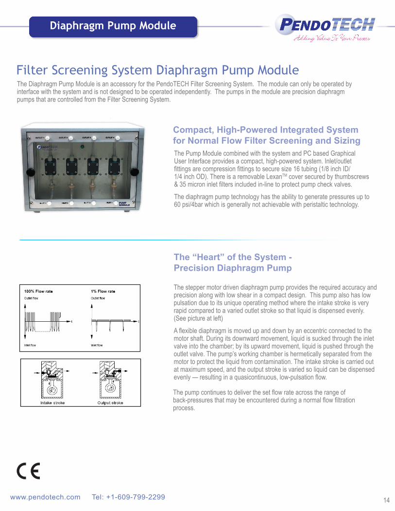
Filter Screening System Diaphragm Pump ModuleThe Diaphragm Pump Module is an accessory for the PendoTECH Filter Screening System. The module can only be operated by interface with the system and is not designed to be operated independently. The pumps in the module are precision diaphragm pumps that are controlled from the Filter Screening System.
The Pump Module combined with the system and PC based Graphical User Interface provides a compact, high-powered system. Inlet/outlet fittings are compression fittings to secure size 16 tubing (1/8 inch ID/ 1/4 inch OD). There is a removable LexanTM cover secured by thumbscrews & 35 micron inlet filters included in-line to protect pump check valves.
The diaphragm pump technology has the ability to generate pressures up to 60 psi/4bar which is generally not achievable with peristaltic technology.
The stepper motor driven diaphragm pump provides the required accuracy and precision along with low shear in a compact design. This pump also has low pulsation due to its unique operating method where the intake stroke is very rapid compared to a varied outlet stroke so that liquid is dispensed evenly. (See picture at left)
A flexible diaphragm is moved up and down by an eccentric connected to the motor shaft. During its downward movement, liquid is sucked through the inlet valve into the chamber; by its upward movement, liquid is pushed through the outlet valve. The pump’s working chamber is hermetically separated from the motor to protect the liquid from contamination. The intake stroke is carried out at maximum speed, and the output stroke is varied so liquid can be dispensed evenly — resulting in a quasicontinuous, low-pulsation flow.
Compact, High-Powered Integrated System for Normal Flow Filter Screening and Sizing
The “Heart” of the System - Precision Diaphragm Pump
The pump continues to deliver the set flow rate across the range of back-pressures that may be encountered during a normal flow filtration process.
www.pendotech.com Tel: +1-609-799-2299
Diaphragm Pump Module

Expansion Options
15
Breakout Box for External Inputs
To Control System To External Transmitters
Turbidity Flow Cell & Measurement Unit
Temperature
PendoTECH Filter Stand
Expansion ModuleExpansion options are available through use of the Analog Inputs Connector on the back panel. External measurements can be logged with all of the other process data. Cables are available to connect pre-configured expansion options or by use of the Expansion Module, individual transmitters may be connected. Popular external measurements are turbidity and temperature.
For turbidity, there are different options depending on measurement range and the number of measurements desired. A single photometer/transmitter can be used or 4 units can be contained in one enclosure
• 880 nm LED light source• Hose barb, luer or sanitary connections to flow path• 1 cm flow path for up to 1900 NTUs• 6.5 cm flow path for up to 300 NTUs
For temperature, the PendoTECH luer temperature sensor conveniently fits in-line for an accurate measurement of fluid temperature. A transmitter is required to read the sensor and send the value to the control system. One to four transmitters in one box are offered. A disposable probe is also available.
Luer Sensor
Luer Sensor Installed in Luer Tee
Single Unit(s) ExpansionModule
System
Single Unit ExpansionModule
System
OR
2 - 4 Units System
The Filter Stand allows the bench space to remain clear for scales and also aides greatly in organizing the cables(this can be customized if needed)
4 Unit Turbidity Module
6.5 cm flow cell with luer connection
Single Use 6.5 cm Turbidity Flow Cell
Photometer
4 Unit Module System For more detail: http://www.pendotech.com/products/cell_removal/Turbidity_Cell_Info.pdf
Disposable Probe
Copyright © 2018 PendoTECH NFFSS-REV6
Hose Barb Temperature sensor - 1/8 inch, 1/4 inch, 1/2 inch available

Specifications
16
Detail SpecificationsEnclosure Dimensions (HxWxD) 4.8” x 13.8” x 10.3” (12.2x35.1x26.3 cm)
Enclosure Weight 9 lbs (4.1 kg)
Enclosure Material Aluminum
Power Requirements 100 - 240 Volts, 50 - 60 Hertz, 2 amp max
Pressure Sensor Inputs PendoTECH Pressure Sensors default configuration- other full-bridge type sensors optional
Pump Control (1 for each pump) Speed Control: 4 - 20mA or 0 - 10 V output
Spare Inputs (standard) Four of 4 - 20 mA and four of 0 - 10V inputs
System Component SpecificationsEnclosure (with legs not retracted)
H x W x D: 9.85”x13.8”x10.3” (25 x 35.1 x 26.3 cm). Approx: 20 lbs. (6.80 kg), Material: Aluminum with powder polyester paint Front panel: 304 Stainless Steel with REGLO-E Peristaltic Panel mount pump; Back panel: anodized aluminum
Power Inlet With Power Switch IEC 320 cord connection, 100 – 240 Volts, 50 – 60 Hertz, 2 amp max
Fuse 2 amps (housed integral with the Power Switch) at full voltage range
Environmental Operating Range All components rated to a temperature range of 5 to 40◦ C. Humidity: 0 to 95% Relative Humidity, no condensation
Tubing Sizes 1/8 inch ID x 1/4 inch OD (Masterflex Size 16), 1/16 inch ID x 3/16 inch OD (Masterflex Size 14)
Fluid Property Range Function of tubing material and pressure rating performance tested up to 30 psi
Analog Pump Control One DB-25 male connector. Configured for 0-5V signals from PendoTECH Filter Screening System. Control System Settings for Pump Setup: Maximum RPMs: 160Size 16: 0.75 mL/rot for max flow of 120 mL/min Size 14: 0.188 mL/rot for max flow of 30 mL/min Accuracy: +/- 5% of value, Repeatability: +/- 1%
Tubing for Connection of Pump to Panel
1/8 inch (0.3175 cm) Hose barb Inlets/Outlets 1/16 inch (0.15875 cm) Hose barb Inlets/Outlets
Peristaltic Pump Module Specification Table
System Component SpecificationsEnclosure (with legs not retracted)
H x W x D: 9.85”x13.8”x10.3” (25 x 35.1 x 26.3 cm). Approx: 15 lbs. (6.80 kg), Material: Aluminum with powder polyester paint Front panel: 304 Stainless Steel with Lexan® cover; Back panel: anodized aluminum
Power Inlet With Power Switch IEC 320 cord connection, 100 – 240 Volts, 50 – 60 Hertz, 2 amp max
Fuse 2 amps (housed integral with the Power Switch) at full voltage range
Environmental Operating Range All components rated to a temperature range of 5 to 40◦ C. Humidity: 0 to 95% Relative Humidity, no condensation
Pump Diaphragm Lifetime >10,000 hours
Diaphragm Pump Fittings Compression fitting for 1/8inch ID/1/4inch OD tubing (Masterflex Size 16)
Fluid Property Range Permissible temperature of the medium being handled: 5 to 80°C. The dosing pump has been developed for liquids with viscosities of up to 150cSt. If particles greater that 25micron are present, a filter is recommended.
Analog Pump Control One DB-25 male connector.Configured for 4-20mA signals from PendoTECH Filter Screening System (if in analog mode)Control System Settings for Pump Setup: 0.5 ml/rotationMaximum RPMs: 200 Flow Range: 2.0 to 100 mL/min Accuracy: +/- 5% of value Repeatability: +/- 1%
Diaphragm Pump Hold Up Volume Total pump: ~0.530 mL
Tubing for Connection of Pump to Panel
1/8 inch ID ID: 0.318cmLength: 12cm per piece Hold-up: 1 mL per pieceTubing total: 2 mL for one train
Hold Up Volume per Train ~2.5 mL
Diaphragm Pump Module Specification Table
Filter Screening System Specification Table
Copyright © 2017 PendoTECH NFFSS-REV6

Warranty/DisclaimerAll descriptions, representations and/or other information concerning Product on the PendoTECH website and/or contained in PendoTECH’s advertisements, brochures, promotional material, or statements made by employees or sales representatives of PendoTECH are solely for general informational purposes only and are not binding upon PendoTECH. No employee or sales representative of PendoTECH shall have any authority to establish, expand or otherwise modify PendoTECH’s warranty associated with the sale of Product. PendoTECH, LLC makes no warranty or representation regarding whether or not a customer’s end use of any PendoTECH product or system infringes the valid intellectual property rights of others. PendoTECH does not direct or instruct customers to use any PendoTECH product or system in combination with particular commercially available pre-sterilized manifolds, remotely operated pinch valves, as such use could possibly be covered by the claims of one or more patents. PendoTECH shall not be liable to BUYER in any manner with respect to Product sold. SELLER, PendoTECH MAKES NO REPRESENTATIONS OR WARRANTIES OF ANY TYPE, EXPRESS OR IMPLIED, AND EXPRESSLY DISCLAIMS AND EXCLUDES ANY REPRESENTATION OR WARRANTY OF MERCHANT-ABILITY, FITNESS FOR A PARTICULAR PURPOSE OR USE, NON-INFRINGEMENT OR WARRANTY ARISING FROM USAGE OF TRADE, COURSE OF DEALING OR PERFORMANCE.” For warranty information see our website at http://www.pendotech.com/warranty
Vmax is a trademark of EMD MilliporeCopyright © 2018 PendoTECH NFFSS-REV6 17
Ordering Information
FOR PENDOTECH PRESSURE SENSORS
See www.pendotech.com/pressure
FOR PENDOTECH TEMPERATURE SENSORS
See www.pendotech.com/temperature
SYSTEMPDKT-PCS-NFFSS PendoTECH Normal Flow Filtration Screening System w/ PC software
PUMPS PUMP-MF-LS-TW Masterflex General Purpose Drive, with RPM display only, 600RPM with EasyLoad II pump head for thin wall L/S tubingsPUMP-MFD-LS-TW Masterflex Peristaltic Digital Pump w/DB25 remote control port for control from system. 600RPM drive w/ EasyLoad II for precision thin
wall L/S tubingPUMP-WM-120-TW Watson-Marlow 120U/DV 200RPM Pump Fitted with 114DV flip-top four roller pumphead for thin tubing
PUMP MODULES
PDKT-NFFSS-PPM Peristaltic Pump Module for PendoTECH Filter Screening System
PDKT-NFFSS-PUMP Diaphragm Pump Module for PendoTECH Filter Screening System
SCALES
SCALE-OHAUS-6200-1 Ohaus Scout Pro model SPX-6201 (6200g x 0.1g) top loading balance w/RS232 output set up for PendoTECH Systems
VESSELS
PDKT-NFFSS-CP Constant pressure vessel: 0-25psi regulator, 0-60psi gauge, 12in polysulfone container with 2.5in TC (~800mL) with outfitted endcaps
PDKT-NFFSS-CP-NR Constant pressure vessel: 12in polysulfone container with 2.5in TC (~800mL) with outfitted endcaps
TURBIDITY
SPEC-880 Turbidity System w/880nm Light Source, 4-20mA Output, panel model, 2 Fiber optic cables, 2 Optical couplers to connect to 1 Flow Cell
SPEC-880-4 Four Station Turbidity System w/880nm Light Source, 4-20mA Output, panel model, 8 Fiber optic cables, 8 Optical couplers to connect to 4 Flow Cells
ACCESSORIES
PDKT-STAND-NFFSS Stainless steel stand for filter screening system
PDKT-BOX-NFFSS Breakout box for analog inputs to 8 connectors