Embed Size (px)
Citation preview

ManualEN
PEM735 Measuring case
Measuring and demonstration case
PEM735-measuring_case_D00240_00_M_XXEN/12.2015 B 9830 0014

© Bender GmbH & Co. KG
All rights reserved.Reprinting only with permission
of the publisher.Subject to change!
Bender GmbH & Co. KGP. O. Box 1161 • 35301 Gruenberg • GermanyLondorfer Str. 65 • 35305 Gruenberg • Germany
Tel.: +49 6401 807-0Fax: +49 6401 807-259
E-Mail: [email protected]
Photos: Bender archives

Tabe of Contents
1. Function and safety ................................................................................ 5
2. Content of the measuring case ............................................................. 6
3. Connecting the measuring case ........................................................... 7
3.1 Front plate ............................................................................................................ 8
3.2 Wiring panel side ............................................................................................... 9
4. Current measurement ......................................................................... 11
4.1 Application of the Rogowski coils ............................................................. 12
4.1.1 Settings on the case ....................................................................................... 13
4.1.2 Mounting Rogowski coils ............................................................................. 14
4.1.3 Settings on the PEM735 ................................................................................ 14
4.2 Application of AUX transformers ............................................................... 15
4.2.1 Settings on the case ....................................................................................... 16
4.2.2 Mounting AUX transformers ....................................................................... 16
4.2.3 Settings PEM735 .............................................................................................. 16
4.3 Use of 3 Rogowski coils and 1 AUX transformer .................................. 17
4.3.1 Settings on the case ....................................................................................... 17
4.3.2 Mounting transformer ................................................................................... 17
4.3.3 Settings PEM735 .............................................................................................. 17
5. Voltage measurement ......................................................................... 18
5.1 Overview material for voltage measurement ....................................... 18
6. Digital inputs and relay outputs ....................................................... 19
6.1 Digital inputs DI1, DI2, DIC ........................................................................... 19
6.2 Relay outputs RO1…2 ................................................................................... 19
7. Network .................................................................................................. 20
3PEM735-measuring_case_D00240_00_M_XXEN/12.2015

Table of Contents
8. Technical data ........................................................................................ 21
9. Ordering information ........................................................................... 23
INDEX ............................................................................................................ 25
4 PEM735-measuring_case_D00240_00_M_XXEN/12.2015

Function and safety
1. Function and safety
The PEM735 measuring and demonstration case is used for mobile measurements to analyse the voltage quality accord-ing to DIN EN 50160 (measurement according to IEC 61000-4-30 class A).
For the use of this measuring case, specialist knowledge is required. It is essential to follow the existing safety regulations!
About this manualIn the schematic presentation, the elements belonging to the Rogowski coils are de-picted in pink and all elements belonging to the AUX transformers are depicted in green.
Risk of fatal injury from electric shock!Incorrect wiring of the measuring voltage cables may cause a short-circuitof the installation, arcs and high short-circuit currents.The secured side of the measuring voltage cable (longer plug) must beconnected to the installation!
Risk of fatal injury from electric shock!
AUX transformers may not be operated as anopen circuit on the secondary side!
Connected AUX transformers must be short-circuited with a jumper wire when not in use!
DANGER
DANGERW1
W2
W3
W4
11
12
42
41
32
3122
21
Rogowski
5PEM735-measuring_case_D00240_00_M_XXEN/12.2015

Content of the measuring case
2. Content of the measuring case
Universal measuring device PEM735 (IP address 192.168.0.10) Integrated WLAN router (IP address 192.168.0.254; admin/admin) 4 flexible Rogowski coils and transducers for current measurement 100…4000 A 1 current transformer clamp C112 (1000 A; 5 kHz) 1 current transformer clamp C148 (configurable 250/500/1000 A; 1 kHz) 5 cables with fuses for voltage measurement Safety test probes (crocodile clips, magnetic test probes, test probes for use with
push-wire terminals) Trolley Case can be locked (padlock not included)
Abb. 2.1: Content of the measuring case
6 PEM735-measuring_case_D00240_00_M_XXEN/12.2015

Connecting the measuring case
3. Connecting the measuring case
For your safety, consider the sequence of the work steps:
1. Configure measuring case mechanically (insert jumper wires for the trans-formers used, adjust transducers for Rogowski coils)
2. Install measuring current transformer
3. Commission measuring case
4. Configure PEM735
5. Install measuring voltage cables
The measuring case is operated with 230 V, 50 Hz. The connecting cable is included.
7PEM735-measuring_case_D00240_00_M_XXEN/12.2015

Connecting the measuring case
3.1 Front plate The case contains the PEM735 connected to the front plate, a router, the transducers for the Rogowski coils and the jumper wires to configure the transformers being used.
Fig. 3.1: Front plateLegend front plate
No. Description
1 Overview of the DIP switch settings for the transducers of the Rogowski coils
2 Transducers for the Rogowski coils
3 Jumper wire slots to configurate the measuring current transformers in use
4 Slots for replacement jumper wires
5 Universal measuring device PEM735
W1
W2
W3
W4
11
12
42
41
32
3122
21
Rogowski
kvarhkWhPEM735
LINETRAXX®
ENTER ESC
8
1
8
1
8
1
8
1
W3 W4W1 W2
1 2
4
5
3
8 PEM735-measuring_case_D00240_00_M_XXEN/12.2015

Connecting the measuring case
3.2 Wiring panel sideAt the side of the measuring case you can find the Power supply of the measuring case Voltage transformer inputs Measuring current transformer inputs Network connection input Digital inputs Relay outputs
Fig. 3.2: Wiring panel side
L1
L2
L3N
PE
Ethernet
AUX
W44241
W3
W2
W1
31
2221
32
1211
Rogowski
1 0
RO24
RO23
RO14
RO13
DI2
DI1
DIC
12
6
7
5
4
3
9PEM735-measuring_case_D00240_00_M_XXEN/12.2015

Connecting the measuring case
Legend wiring panel side
No. Description
1 On/off switch of the measuring case
2 Measuring voltage inputs
3 Power supply socket for measuring case
4 Ethernet connection socket
5 Measuring current transformer inputs
6 Digital inputs and relay outputs
7 Connection Rogowski coils
10 PEM735-measuring_case_D00240_00_M_XXEN/12.2015

Current measurement
4. Current measurement
The universal measuring device PEM735 integrated in the measuring case is set to the "load meter arrow system".
The measuring case operates with Rogowski coils (on the left side of the image) and AUX transformers (on the right side of the image).
Fig. 4.1: Measuring current transformer included in the scope of delivery (left: 4 Rogowski coils, right: 2 current transformer clamps)
When installing the transformers, make sure that the imprinted directionarrows point at the load. Otherwise you will receive incorrectmeasurement values.
11PEM735-measuring_case_D00240_00_M_XXEN/12.2015

Current measurement
4.1 Application of the Rogowski coilsThe 4 provided Rogowski coils are bundled together at one end with a plug that is con-nected to the socket on the side of the measuring case. For easier assignment of the measurement values, the Rogowski coils are labelled (5A1…4).
Fig. 4.2: Rogowski coil
Legend Rogowski coil
No. Description
1 Plug of the 4 Rogowski coils
2 Coil enclosure
3 Bayonet connection
4 Measuring coil (orange)
5 Signal cable (black)
6 Mounting aid for busbar measurement
1
23
4
6
5
12 PEM735-measuring_case_D00240_00_M_XXEN/12.2015

Current measurement
4.1.1 Settings on the case 1. Disconnect measuring case.
2. Set the transducers W1…4 for the Rogowski coils to the expected measuring range using the DIP switches.
DIP switch Use the DIP switches to set the conversion ratio of the Rogowski coils at the transducers.
Table 4.1: Table DIP switches for transducers
For "Compensation", the length of the used Rogowski coil is indicated in mm. The sup-plied Rogowski coils must be set to 600.
3. All 8 jumper wires must be inserted in position "Rogowski".
Changes to the DIP switches can only be carried out when the powersupply is disconnected!
DIP switch for transducers (conversion table for primary currents Rogowski)
1 = 4000 A
In the example, the range "630 A" is set.2 = 2000 A
3 = 1500 A
4 = 1000 A
5 = 630 A
6 = 400 A
7 = 250 A
8 = 100 A
8
1
W1
W2
W3
W4
11
12
42
41
32
3122
21
Rogowski
13PEM735-measuring_case_D00240_00_M_XXEN/12.2015
Current measurement
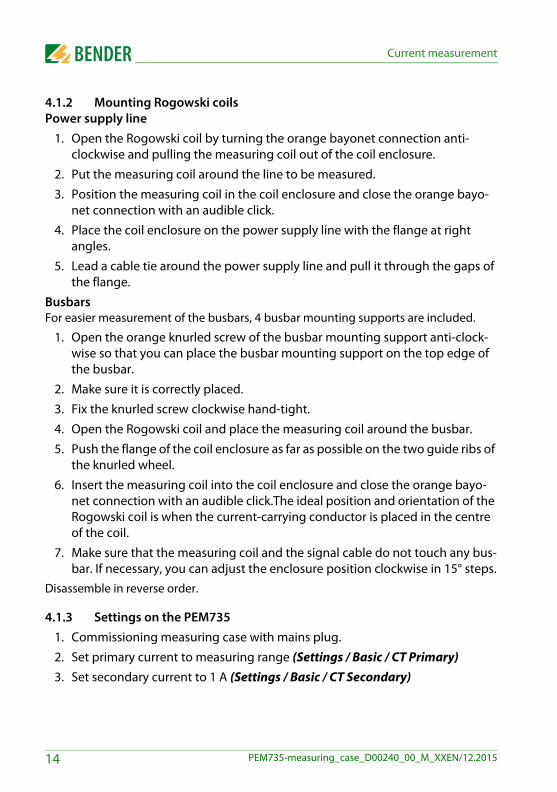
4.1.2 Mounting Rogowski coilsPower supply line
1. Open the Rogowski coil by turning the orange bayonet connection anti-clockwise and pulling the measuring coil out of the coil enclosure.
2. Put the measuring coil around the line to be measured.
3. Position the measuring coil in the coil enclosure and close the orange bayo-net connection with an audible click.
4. Place the coil enclosure on the power supply line with the flange at right angles.
5. Lead a cable tie around the power supply line and pull it through the gaps of the flange.
BusbarsFor easier measurement of the busbars, 4 busbar mounting supports are included.
1. Open the orange knurled screw of the busbar mounting support anti-clock-wise so that you can place the busbar mounting support on the top edge of the busbar.
2. Make sure it is correctly placed.
3. Fix the knurled screw clockwise hand-tight.
4. Open the Rogowski coil and place the measuring coil around the busbar.
5. Push the flange of the coil enclosure as far as possible on the two guide ribs of the knurled wheel.
6. Insert the measuring coil into the coil enclosure and close the orange bayo-net connection with an audible click.The ideal position and orientation of the Rogowski coil is when the current-carrying conductor is placed in the centre of the coil.
7. Make sure that the measuring coil and the signal cable do not touch any bus-bar. If necessary, you can adjust the enclosure position clockwise in 15° steps.
Disassemble in reverse order.
4.1.3 Settings on the PEM7351. Commissioning measuring case with mains plug.
2. Set primary current to measuring range (Settings / Basic / CT Primary)3. Set secondary current to 1 A (Settings / Basic / CT Secondary)
14 PEM735-measuring_case_D00240_00_M_XXEN/12.2015

Current measurement
4.2 Application of AUX transformers
Example: Application of 3 AUX transformers. AUX4 not in use, therefore short-circuited
Up to 4 AUX transformers can be connectedto the measuring case.
Risk of fatal injury from electric shock!
AUX transformers may not be operated as an open circuit on thesecondary side!
Connected AUX transformers must be short-circuited with a jumper wirewhen not in use!
When using your own measuring current transformers, be aware thatthe secondary current may have a maximum of 5 A!
DANGER
W1
W2
W3
W4
11
12
42
41
32
3122
21
Rogowski
15PEM735-measuring_case_D00240_00_M_XXEN/12.2015
Current measurement
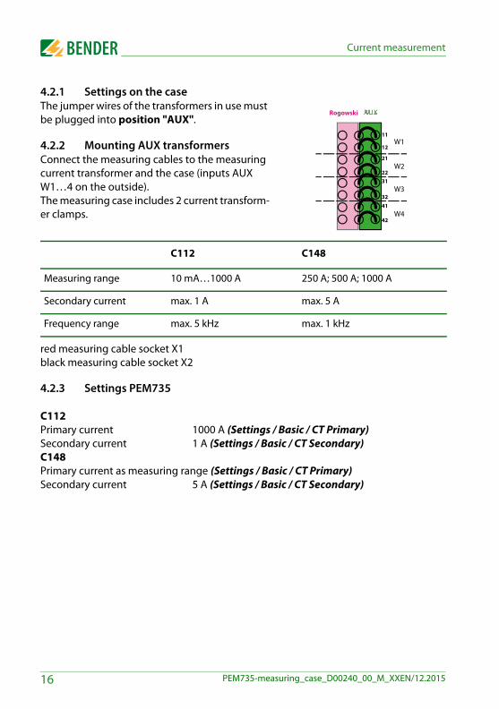
4.2.1 Settings on the caseThe jumper wires of the transformers in use must be plugged into position "AUX".
4.2.2 Mounting AUX transformersConnect the measuring cables to the measuring current transformer and the case (inputs AUX W1…4 on the outside).The measuring case includes 2 current transform-er clamps.
red measuring cable socket X1black measuring cable socket X2
4.2.3 Settings PEM735
C112Primary current 1000 A (Settings / Basic / CT Primary)Secondary current 1 A (Settings / Basic / CT Secondary) C148Primary current as measuring range (Settings / Basic / CT Primary)Secondary current 5 A (Settings / Basic / CT Secondary)
C112 C148
Measuring range 10 mA…1000 A 250 A; 500 A; 1000 A
Secondary current max. 1 A max. 5 A
Frequency range max. 5 kHz max. 1 kHz
W1
W2
W3
W4
11
12
42
41
32
3122
21
Rogowski
16 PEM735-measuring_case_D00240_00_M_XXEN/12.2015
Current measurement
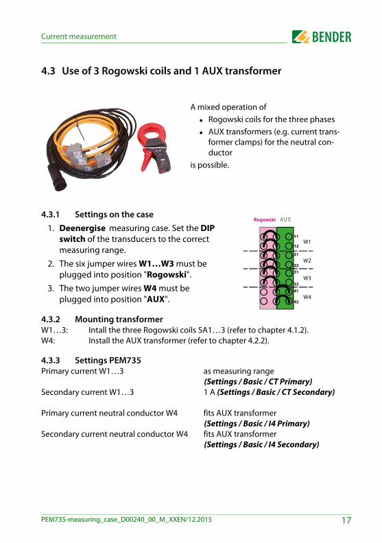
4.3 Use of 3 Rogowski coils and 1 AUX transformer
4.3.1 Settings on the case1. Deenergise measuring case. Set the DIP
switch of the transducers to the correct measuring range.
2. The six jumper wires W1…W3 must be plugged into position "Rogowski".
3. The two jumper wires W4 must be plugged into position "AUX".
4.3.2 Mounting transformerW1…3: Intall the three Rogowski coils 5A1…3 (refer to chapter 4.1.2).W4: Install the AUX transformer (refer to chapter 4.2.2).
4.3.3 Settings PEM735Primary current W1…3 as measuring range
(Settings / Basic / CT Primary)Secondary current W1…3 1 A (Settings / Basic / CT Secondary)
Primary current neutral conductor W4 fits AUX transformer (Settings / Basic / I4 Primary)
Secondary current neutral conductor W4 fits AUX transformer (Settings / Basic / I4 Secondary)
A mixed operation of Rogowski coils for the three phases AUX transformers (e.g. current trans-
former clamps) for the neutral con-ductor
is possible.
W1
W2
W3
W4
11
12
42
41
32
3122
21
Rogowski
17PEM735-measuring_case_D00240_00_M_XXEN/12.2015
Voltage measurement
5. Voltage measurement
5.1 Overview material for voltage measurement
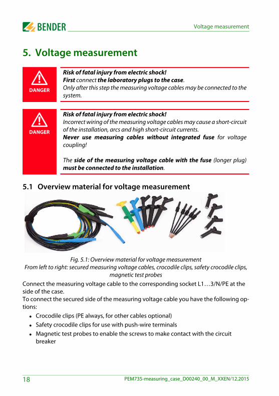
Fig. 5.1: Overview material for voltage measurementFrom left to right: secured measuring voltage cables, crocodile clips, safety crocodile clips,
magnetic test probesConnect the measuring voltage cable to the corresponding socket L1…3/N/PE at the side of the case. To connect the secured side of the measuring voltage cable you have the following op-tions: Crocodile clips (PE always, for other cables optional) Safety crocodile clips for use with push-wire terminals Magnetic test probes to enable the screws to make contact with the circuit
breaker
Risk of fatal injury from electric shock!First connect the laboratory plugs to the case.Only after this step the measuring voltage cables may be connected to thesystem.
Risk of fatal injury from electric shock!Incorrect wiring of the measuring voltage cables may cause a short-circuitof the installation, arcs and high short-circuit currents.Never use measuring cables without integrated fuse for voltagecoupling!
The side of the measuring voltage cable with the fuse (longer plug)must be connected to the installation.
DANGER
DANGER
18 PEM735-measuring_case_D00240_00_M_XXEN/12.2015

Digital inputs and relay outputs
6. Digital inputs and relay outputs
The digital inputs and the relay outputs are located at the outside of the measuring case.
6.1 Digital inputs DI1, DI2, DICThe measuring case offers 2 digital inputs. The inputs are supplied by a galvanically iso-lated DC 24 V voltage. An external circuit providing at least a current of Imin > 2.4 mA is required for triggering the inputs.
Fig. 6.1: Digital inputs
6.2 Relay outputs RO1…2The measuring case features two relay outputs. .
Table 6.1: Relay outputs
Rated operational voltage
AC 230 V DC 24 V AC 110 V DC 12 V
Rated operational current
5 A 5 A 6 A 5 A
DI1 DI2 DIC
RO13 RO14
RO23 RO24
19PEM735-measuring_case_D00240_00_M_XXEN/12.2015

Network
7. Network
Thanks to the integrated router you can access the measurement results and settings of the PEM735 via WLAN. Additional notes regarding the use of the PEM735, the Modbus register overview and the web application can be found in the manual and annexes of the PEM735.Ethernet addressPEM735: IP 192.168.0.10WLAN: IP 192.168.0.254 (admin/admin)
For seamless communication it is important that the PEM735 and the router are in the same network.
Default setting: Access point DHCP activated
Connecting a device to the WLAN (SSID=PEM735)
Integrating the WLAN into existing networks: refer to WLAN router documentation.
20 PEM735-measuring_case_D00240_00_M_XXEN/12.2015

Technical data
8. Technical data
Insulation coordination
Measuring circuitRated insulation voltage ................................................................................................................... 600 VOvervoltage category................................................................................................................................ IIIPollution degree.........................................................................................................................................2
Supply circuitRated insulation voltage .................................................................................................................... 300 VOvervoltage category................................................................................................................................. IIPollution degree.........................................................................................................................................2
Supply voltageRated supply voltage US ....................................................................................................... 110…240 VFrequency range of US ..............................................................................................................47…63 Hz
Measuring circuit
Measuring voltage inputsUL1-N,L2-N,L3-N .............................................................................................................................. 400 VUL1-L2,L2-L3,L3-L1 ......................................................................................................................... 690 VMeasuring range ..............................................................................................................10… 120 % UnRated frequency ........................................................................................................................45…65 HzInternal resistance (L-N) ................................................................................................................> 6 MΩ
Measuring current inputsExternal measuring current transformers ............................ should at least comply with accuracy 0.2 SBurden.................................................................................................. n.A., internal current transformersMeasuring range ..............................................................................................................0.1… 120 % InMeasuring current transformer conversion ratio, secondary ........................................................1…5 AMeasuring current transformer conversion ratio, primary .................................................. 1…30000 A
Accuracies (mv = of measured value/fs = of full scale value) Phase voltage UL1-N, UL2-N, UL3-N ......................................................................................... ± 0.1 % mvCurrent ................................................................................................................± 0.1 % mv + 0.05 % fsFrequency ................................................................................................................................. ± 0.005 HzPhasing ............................................................................................................................................... ± 1 °Measurement of the active energy ................................ acc. to DIN EN 62053-22 (VDE 0418 Part 3-22)Measurement of the voltage r.m.s. values.............................................................................................................................................................................. acc. to DIN EN 61557-12 (VDE 0413-12), chapter 4.7.6
21PEM735-measuring_case_D00240_00_M_XXEN/12.2015

Technical data
Measurement of the phase current r.m.s. values .................................................................................................................................................................. acc. to DIN EN 61557-12 (VDE 0413-12), chapter 4.7.5
Frequency measurement ....................................................................................................................................................................................................... acc. to DIN EN 61557-12 (VDE 0413-12), chapter 4.7.4
Measurement of the harmonics acc. to DIN EN 61000-4-7 class A
InterfaceInterface/protocol ....................................................................................................... RJ-45, Modbus TCP
Switching elementsOutputs (RO) ................................................................................................................... 2 x N/O contactsOperating principle ............................................................................................................. N/O operationRated operational voltage .........................................AC 230 V .....DC 24 V .........AC 110 V ...... DC 12 VRated operational current ..........................................5 A ..............5 A ................6 A ........................5 AMinimum contact rating ........................................................................................1 mA at AC/DC ≥ 10 VInputs ..............................................................................................2 electrically separated digital inputsImin ................................................................................................................................................... 2.4 mAUDI ................................................................................................................................................... DC 24 V
Environment/EMCOperating temperature........................................................................................................... 0…+ 40 °CClassification of climatic conditions ......................................................................... acc. to DIN EN 60721Height .................................................................................................................................... up to 4000 m
OtherDegree of protection............................................................................................................................. IP20Dimensions .................................................................................................. approx. 556 x 416 x 295 mmWeight ...........................................................................................................................................≤ 16 kg
22 PEM735-measuring_case_D00240_00_M_XXEN/12.2015

Ordering information
9. Ordering information
Type Art. no.
PEM735 Measuring case B 9830 0014
23PEM735-measuring_case_D00240_00_M_XXEN/12.2015

Ordering information
24 PEM735-measuring_case_D00240_00_M_XXEN/12.2015

INDEX
AAUX transformers 15
BBayonet connection 12
CCoil enclosure 12Compensation 13Connecting the measuring case 7Current measurement 11
DDigital inputs 9, 19DIP switch 13Direction arrows 11
FFront plate 8
MMeasuring coil 12Measuring current transformer inputs 9Mounting aid 12Mounting Rogowski coils busbars 14Mounting Rogowski coils power supply line 14
NNetwork 20Network connection 9
PPower supply 9
RRelay outputs 9, 19Rogowski coil 12
SSignal cable 12
VVoltage measurement 18Voltage transformer inputs 9
WWiring panel side 9
25PEM735-measuring_case_D00240_00_M_XXEN/12.2015

INDEX
26 PEM735-measuring_case_D00240_00_M_XXEN/12.2015


Bender GmbH & Co. KGP. O. Box 1161 • 35301 Gruenberg • GermanyLondorfer Str. 65 • 35305 Gruenberg • Germany
Tel.: +49 6401 807-0Fax: +49 6401 807-259
E-Mail: [email protected]
Photos: Bender archives