Embed Size (px)
Citation preview

PEM Fuel Cell Integration With a Hydrogen Generator
on a Bench
FINAL REPORT June 2001
Submitted by
NJDOT Research Project Managers Michael Strizki, November 16, 1999 – June 16, 2000
Donald Borowski, June 17, 2000 – June 31, 2000 Henry Schweber, July 1, 2000 – June 12, 2001
FHWA-NJ-2001-034
In cooperation with
New Jersey Department of Transportation
Division of Research and Technology and
U.S. Department of Transportation Federal Highway Administration
Dr. Ali Maher** Professor and Chairman
Mr. Patrick J. Szary* Research Engineer
*Center for Advanced Infrastructure & Transportation (CAIT) ** Dept. of Civil & Environmental Engineering
Rutgers, The State University Piscataway, NJ 08854-8014

Disclaimer Statement
"The contents of this report reflect the views of the author(s) who is (are) responsible for the facts and the
accuracy of the data presented herein. The contents do not necessarily reflect the official views or policies of the New Jersey Department of Transportation or the Federal Highway Administration. This report does not constitute
a standard, specification, or regulation."
The contents of this report reflect the views of the authors, who are responsible for the facts and the accuracy of the
information presented herein. This document is disseminated under the sponsorship of the Department of Transportation, University Transportation Centers Program, in the interest of information exchange. The U.S. Government assumes no
liability for the contents or use thereof.
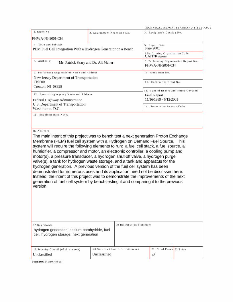
1. Report No. 2 . G o v e r n m e n t A c c e s s i o n N o .
T E C H N I C A L R E P O RT S T A N D A R D T I T L E P A G E
3 . R e c i p i e n t ’ s C a t a l o g N o .
5 . R e p o r t D a t e
8 . P e r f o r m i n g O r g a n i z a t i o n R e p o r t N o .
6. P e r f o r m i n g O r g a n i z a t i o n C o d e
4 . T i t l e a n d S u b t i t l e
7 . A u t h o r ( s )
9 . P e r f o r m i n g O r g a n i z a t i o n N a m e a n d A d d r e s s 1 0 . W o r k U n i t N o .
1 1 . C o n t r a c t o r G r a n t N o .
1 3 . T y p e o f R e p or t a n d P e r i o d C o v e r e d
1 4 . S p o n s o r i n g A g e n c y C o d e
1 2 . S p o n s o r i n g A g e n c y N a m e a n d A d d r e s s
1 5 . S u p p l e m e n t a r y N o t e s
16. A b s t r a c t
17. K e y W o r d s
19. S e c u r i t y C l a s s i f ( o f t h i s r e p o r t )
Form DOT F 1700.7 (8-69)
20. S e c u r i t y C l a s s i f . ( o f t h i s p a g e )
18. D i s t r i b u t i o n S t a t e m e n t
2 1 . N o o f P a g e s 22. P r i c e
June 2001
CAIT/Rutgers
Final Report 11/16/1999 - 6/12/2001
FHWA-NJ-2001-034
New Jersey Department of Transportation CN 600 Trenton, NJ 08625
Federal Highway Administration U.S. Department of Transportation Washington, D.C.
The main intent of this project was to bench test a next generation Proton Exchange Membrane (PEM) fuel cell system with a Hydrogen on Demand Fuel Source. This system will require the following elements to run: a fuel cell stack, a fuel source, a humidifier, a compressor and motor, an electronic controller, a cooling pump and motor(s), a pressure transducer, a hydrogen shut-off valve, a hydrogen purge valve(s), a tank for hydrogen waste storage, and a tank and apparatus for the hydrogen generation. A previous version of the fuel cell system has been demonstrated for numerous uses and its application need not be discussed here. Instead, the intent of this project was to demonstrate the improvements of the next generation of fuel cell system by bench-testing it and comparing it to the previous version.
hydrogen generation, sodium borohydride, fuel cell, hydrogen storage, next generation
Unclassified Unclassified
43
FHWA-NJ-2001-034
Mr. Patrick Szary and Dr. Ali Maher
PEM Fuel Cell Integration With a Hydrogen Generator on a Bench

ii
TABLE OF CONTENTS Abstract.....................................................................................................................................1 Background ..............................................................................................................................1 Project Goals ............................................................................................................................1 Introduction...............................................................................................................................2
Fuel Cells Background and Theory................................................................................2 Research and Development ...................................................................................................3
Next Generation Fuel Cell Development at H-Power Inc.............................................3 Air Flow and Thermal Management of Fuel Cell Stacks ..............................................6 Advanced Fuel Cell / Hydrogen Generator Development............................................8 Hydrogen Storage Background and Theory..................................................................8 Hydrogen-On-Demand Development at Millennium Cell, Inc. .................................9 Pressure and Thermal Management of Hydrogen-On-Demand System ..............13 Fuel Cell System Design by Recon Industrial Controls Corporation.........................15 Estimated Ability Calculations.......................................................................................19 Consumption rates and run times ................................................................................20
Conclusions ............................................................................................................................20 References Cited ...................................................................................................................22 Appendix 1 - MSDS and Product Information 13 .................................................................23 Appendix 2 – Commercially Available Sodium Borohydride Product Information 14........33 Appendix 3 - Additional Technical Pictorial .........................................................................35
iii
LIST OF FIGURES Figure 1 High-power fuel cell test stand at H-Power. ...........................................................2 Figure 2 Bench test results of the fuel cell stack number two at H-Power.........................4 Figure 3 Bench test results of the fuel cell stack number two at H Power. ........................5 Figure 4 Air Flow Diagram ......................................................................................................6 Figure 5. Results obtained on the Becker blower................................................................7 Figure 6. Closer look at the regenerative blower. ................................................................7 Figure 7 Initial hydrogen generation flow rate experiments utilizing the Hydrogen-On-
Demand generator. ....................................................................................................10 Figure 8 Millennium Cell, Inc. Hydrogen-On-Demand System showing pumps siphon
the sodium borohydride from the fuel tank and deliver it into the reaction chamber followed by the coolant system utilizing heat exchanger to cool the hydrogen stream. ............................................................................................................................11
Figure 9 Spent fuel condensate / sodium borate tank (left) and fuel tank (right).............12 Figure 10 Crystallized sodium borate byproduct of reaction. ............................................13 Figure 11. Interface Software for monitoring fuel Cell Stack Operating Variables. ........16 Figure 12. Data Log Module for the continuous logging of date/time stamped data......17 Figure 13. The calculation of the fuel cell stack voltage. Graph shown is based on 60
cell stack. ........................................................................................................................18 Figure 14. Polarization chart showing the voltage vs. current cross plotted against the
stack power. ...................................................................................................................18 Figure 15 Millennium Cell, Inc. Hydrogen Generator Model 1 designed to power a 1.2
kW fuel cell. ....................................................................................................................35 Figure 16 Millennium Cell, Inc. hydrogen generator test stand used to develop hydrogen
generator design prior to installation in the vehicle. ...................................................35 Figure 17 Hydrogen generator test stand condenser water reclamation tank used to
develop hydrogen generator design prior to installation in the vehicle.....................36 Figure 18 Fuel cell air compressor assembly. ....................................................................36 Figure 19 Custom stainless steel radiator to cool fuel cell system. ..................................36 Figure 20 Two 7 kW (gross) fuel cell stacks installed in a vehicle....................................37 Figure 21 Schematic of Hydrogen Generation System......................................................37 LIST OF TABLES Table 1. Comparison Between Previous Generation and Next Generation Fuel Cell Systems. ………………………………………………………………………………………..15

iv
ACKNOWLEDGMENTS This project was conducted in cooperation and under sponsorship of the New Jersey Department of Transportation (NJDOT). The principal investigators express their gratitude to the NJDOT for funding the research described herein.
1
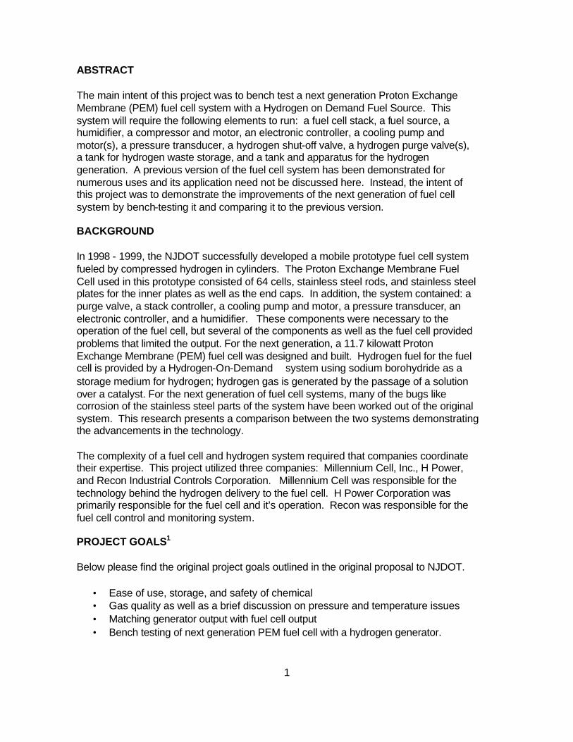
ABSTRACT The main intent of this project was to bench test a next generation Proton Exchange Membrane (PEM) fuel cell system with a Hydrogen on Demand Fuel Source. This system will require the following elements to run: a fuel cell stack, a fuel source, a humidifier, a compressor and motor, an electronic controller, a cooling pump and motor(s), a pressure transducer, a hydrogen shut-off valve, a hydrogen purge valve(s), a tank for hydrogen waste storage, and a tank and apparatus for the hydrogen generation. A previous version of the fuel cell system has been demonstrated for numerous uses and its application need not be discussed here. Instead, the intent of this project was to demonstrate the improvements of the next generation of fuel cell system by bench-testing it and comparing it to the previous version. BACKGROUND In 1998 - 1999, the NJDOT successfully developed a mobile prototype fuel cell system fueled by compressed hydrogen in cylinders. The Proton Exchange Membrane Fuel Cell used in this prototype consisted of 64 cells, stainless steel rods, and stainless steel plates for the inner plates as well as the end caps. In addition, the system contained: a purge valve, a stack controller, a cooling pump and motor, a pressure transducer, an electronic controller, and a humidifier. These components were necessary to the operation of the fuel cell, but several of the components as well as the fuel cell provided problems that limited the output. For the next generation, a 11.7 kilowatt Proton Exchange Membrane (PEM) fuel cell was designed and built. Hydrogen fuel for the fuel cell is provided by a Hydrogen-On-Demand system using sodium borohydride as a storage medium for hydrogen; hydrogen gas is generated by the passage of a solution over a catalyst. For the next generation of fuel cell systems, many of the bugs like corrosion of the stainless steel parts of the system have been worked out of the original system. This research presents a comparison between the two systems demonstrating the advancements in the technology. The complexity of a fuel cell and hydrogen system required that companies coordinate their expertise. This project utilized three companies: Millennium Cell, Inc., H Power, and Recon Industrial Controls Corporation. Millennium Cell was responsible for the technology behind the hydrogen delivery to the fuel cell. H Power Corporation was primarily responsible for the fuel cell and it’s operation. Recon was responsible for the fuel cell control and monitoring system. PROJECT GOALS1 Below please find the original project goals outlined in the original proposal to NJDOT.
• Ease of use, storage, and safety of chemical • Gas quality as well as a brief discussion on pressure and temperature issues • Matching generator output with fuel cell output • Bench testing of next generation PEM fuel cell with a hydrogen generator.

2
• Discussion of potential refinements • The report will also contain a brief discussion on the background description of
hydrogen storage.
INTRODUCTION Fuel Cells Background and Theory “Fuel cells have no moving parts, are nonpolluting and quiet and produce water as the only byproduct.”2A Proton Exchange Membrane Fuel Cell (PEMFC) is a device that electrochemically combines hydrogen and oxygen to produce electricity and pure water. There are no other side-products or emissions produced. Pure oxygen is required for fuel cells used in outer space; but in most terrestrial applications the oxygen is supplied to the cathode by flowing air through the cell. For this project, pure hydrogen will be generated by a liquid hydride technology developed for this project. The hydrogen is consumed at the rate required by the electrical load. In this way a fuel cell is different from batteries. A battery must be recharged each time it uses the electrical charge that was stored in it, but a fuel cell will continue to generate electricity as long as hydrogen and oxygen are supplied to its cells3. The first problem is that even though fuel cells are a highly efficient and clean method for converting hydrogen to electric power, they require refinement and further development. A sub-goal for this project was to make improvements in PEM fuel cell weight, volume, efficiency, reliability, and life expectancy. H-Power Corporation primarily undertook these tasks. Shown in Figure 1 is a test stand where fuel cell stacks are tested and developed.
Figure 1 High-power fuel cell test stand at H-Power.
3
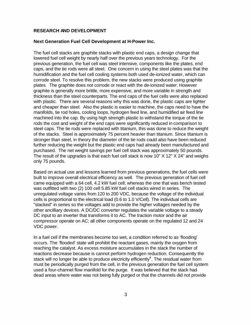
RESEARCH AND DEVELOPMENT Next Generation Fuel Cell Development at H-Power Inc. The fuel cell stacks are graphite stacks with plastic end caps, a design change that lowered fuel cell weight by nearly half over the previous years technology. For the previous generation, the fuel cell was steel intensive, components like the plates, end caps, and the tie rods were all steel. One concern in using the steel plates was that the humidification and the fuel cell cooling systems both used de-ionized water, which can corrode steel. To resolve this problem, the new stacks were produced using graphite plates. The graphite does not corrode or react with the de-ionized water. However graphite is generally more brittle, more expensive, and more variable in strength and thickness than the steel counterparts. The end caps of the fuel cells were also replaced with plastic. There are several reasons why this was done, the plastic caps are lighter and cheaper than steel. Also the plastic is easier to machine, the caps need to have the manifolds, tie rod holes, cooling loops, hydrogen feed line, and humidified air feed line machined into the cap. By using high strength plastic to withstand the torque of the tie rods the cost and weight of the end caps were significantly reduced in comparison to steel caps. The tie rods were replaced with titanium, this was done to reduce the weight of the stacks. Steel is approximately 75 percent heavier than titanium. Since titanium is stronger than steel, in theory the diameter of the tie rods could also have been reduced further reducing the weight but the plastic end caps had already been manufactured and purchased. The net weight savings per fuel cell stack was approximately 50 pounds. The result of the upgrades is that each fuel cell stack is now 10" X 12" X 24" and weighs only 75 pounds. Based on actual use and lessons learned from previous generations, the fuel cells were built to improve overall electrical efficiency as well. The previous generation of fuel cell came equipped with a 64 cell, 4.2 kW fuel cell; whereas the one that was bench tested was outfitted with two (2) 100 cell 5.85 kW fuel cell stacks wired in series. The unregulated voltage varies from 120 to 200 VDC, because the voltage of the individual cells is proportional to the electrical load (0.6 to 1.0 V/Cell). The individual cells are "stacked" in series so the voltages add to provide the higher voltages needed by the other ancilliary devices. A DC/DC converter regulates the variable voltage to a steady DC input to an inverter that transforms it to AC. The traction motor and the air compressor operate on AC; all other components operate on the regulated 12 and 24 VDC power. In a fuel cell if the membranes become too wet, a condition referred to as ‘flooding’ occurs. The ‘flooded’ state will prohibit the reactant gases, mainly the oxygen from reaching the catalyst. As excess moisture accumulates in the stack the number of reactions decrease because is cannot perform hydrogen reduction. Consequently the stack will no longer be able to produce electricity efficiently4. The residual water from must be periodically purged from the cell, in the previous generation the fuel cell system used a four-channel flow manifold for the purge. It was believed that the stack had dead areas where water was not being fully purged or that the channels did not provide
4
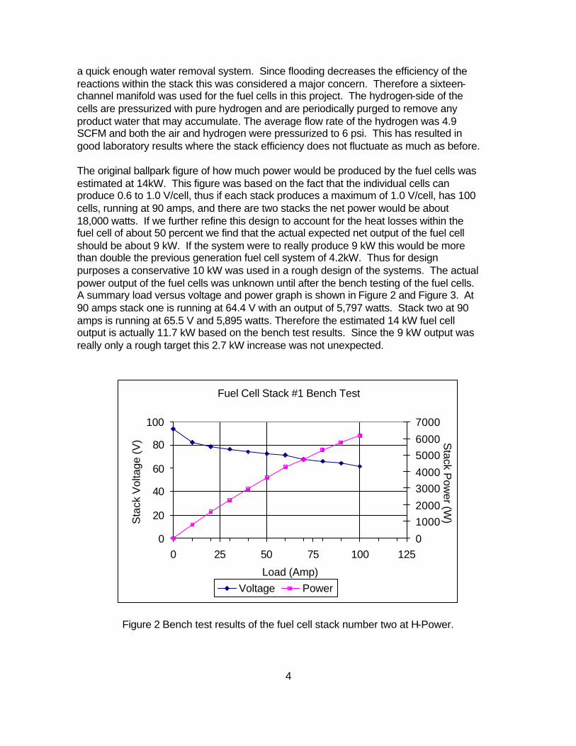
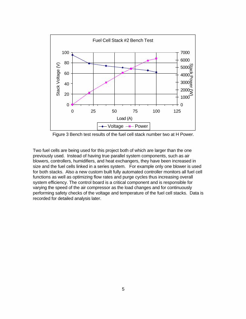
a quick enough water removal system. Since flooding decreases the efficiency of the reactions within the stack this was considered a major concern. Therefore a sixteen-channel manifold was used for the fuel cells in this project. The hydrogen-side of the cells are pressurized with pure hydrogen and are periodically purged to remove any product water that may accumulate. The average flow rate of the hydrogen was 4.9 SCFM and both the air and hydrogen were pressurized to 6 psi. This has resulted in good laboratory results where the stack efficiency does not fluctuate as much as before. The original ballpark figure of how much power would be produced by the fuel cells was estimated at 14kW. This figure was based on the fact that the individual cells can produce 0.6 to 1.0 V/cell, thus if each stack produces a maximum of 1.0 V/cell, has 100 cells, running at 90 amps, and there are two stacks the net power would be about 18,000 watts. If we further refine this design to account for the heat losses within the fuel cell of about 50 percent we find that the actual expected net output of the fuel cell should be about 9 kW. If the system were to really produce 9 kW this would be more than double the previous generation fuel cell system of 4.2kW. Thus for design purposes a conservative 10 kW was used in a rough design of the systems. The actual power output of the fuel cells was unknown until after the bench testing of the fuel cells. A summary load versus voltage and power graph is shown in Figure 2 and Figure 3. At 90 amps stack one is running at 64.4 V with an output of 5,797 watts. Stack two at 90 amps is running at 65.5 V and 5,895 watts. Therefore the estimated 14 kW fuel cell output is actually 11.7 kW based on the bench test results. Since the 9 kW output was really only a rough target this 2.7 kW increase was not unexpected.
Figure 2 Bench test results of the fuel cell stack number two at H-Power.
Fuel Cell Stack #1 Bench Test
0
20
40
60
80
100
0 25 50 75 100 125
Load (Amp)
Sta
ck V
olta
ge (V
)
0
10002000
30004000
50006000
7000
Stack P
ower (W
)
Voltage Power
5
Fuel Cell Stack #2 Bench Test
0
20
40
60
80
100
0 25 50 75 100 125
Load (A)
Sta
ck V
olta
ge (
V)
0
1000
2000
3000
4000
5000
6000
7000S
tack Pow
er (W)
Voltage Power
Figure 3 Bench test results of the fuel cell stack number two at H Power. Two fuel cells are being used for this project both of which are larger than the one previously used. Instead of having true parallel system components, such as air blowers, controllers, humidifiers, and heat exchangers, they have been increased in size and the fuel cells linked in a series system. For example only one blower is used for both stacks. Also a new custom built fully automated controller monitors all fuel cell functions as well as optimizing flow rates and purge cycles thus increasing overall system efficiency. The control board is a critical component and is responsible for varying the speed of the air compressor as the load changes and for continuously performing safety checks of the voltage and temperature of the fuel cell stacks. Data is recorded for detailed analysis later.
6
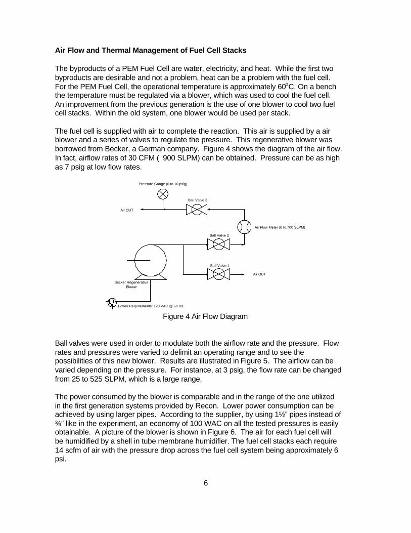
Air Flow and Thermal Management of Fuel Cell Stacks The byproducts of a PEM Fuel Cell are water, electricity, and heat. While the first two byproducts are desirable and not a problem, heat can be a problem with the fuel cell. For the PEM Fuel Cell, the operational temperature is approximately 60oC. On a bench the temperature must be regulated via a blower, which was used to cool the fuel cell. An improvement from the previous generation is the use of one blower to cool two fuel cell stacks. Within the old system, one blower would be used per stack. The fuel cell is supplied with air to complete the reaction. This air is supplied by a air blower and a series of valves to regulate the pressure. This regenerative blower was borrowed from Becker, a German company. Figure 4 shows the diagram of the air flow. In fact, airflow rates of 30 CFM (∼900 SLPM) can be obtained. Pressure can be as high as 7 psig at low flow rates.
Ball Valve 3
Ball Valve 2
Ball Valve 1
Air Flow Meter (0 to 700 SLPM)
Becker RegenerativeBlower
Pressure Gauge (0 to 10 psig)
Air OUT
Air OUT
Power Requirements: 120 VAC @ 60 Hz
Figure 4 Air Flow Diagram Ball valves were used in order to modulate both the airflow rate and the pressure. Flow rates and pressures were varied to delimit an operating range and to see the possibilities of this new blower. Results are illustrated in Figure 5. The airflow can be varied depending on the pressure. For instance, at 3 psig, the flow rate can be changed from 25 to 525 SLPM, which is a large range. The power consumed by the blower is comparable and in the range of the one utilized in the first generation systems provided by Recon. Lower power consumption can be achieved by using larger pipes. According to the supplier, by using 1½” pipes instead of ¾” like in the experiment, an economy of 100 WAC on all the tested pressures is easily obtainable. A picture of the blower is shown in Figure 6. The air for each fuel cell will be humidified by a shell in tube membrane humidifier. The fuel cell stacks each require 14 scfm of air with the pressure drop across the fuel cell system being approximately 6 psi.

7
Becker Regenerative Blower Performances
0
200
400
600
800
1000
1200
1400
1600
1800
2000
0 1 2 3 4 5 6 7
Pressure (psig)
Air
Flo
w R
ate
(SL
PM
), P
ow
er
Con
sum
ed (
WA
C)
61
62
63
64
65
66
67
68
69
70
Sound Level @
1 meter (dB
A)
Air Flow Min (SLPM)
Air Flow Max (SLPM)
Power Consumed Min (WAC)
Power Consumed Max (WAC)
Sound Level (dBA)
Figure 5. Results obtained on the Becker blower.
Figure 6. Closer look at the regenerative blower.

8
Advanced Fuel Cell / Hydrogen Generator Development
For the fuel cell, the cell will continue to provide energy output if there is a continuous supply of fuel input. The hydrogen fuel will be provided by a Hydrogen-On-Demand system using sodium borohydride as a storage medium for hydrogen. The hydrogen generation system could potentially be used in the heating, power generation, mobile communications, and many other stationary and mobile industry applications, as these are outside the scope of work, they shall not be discussed.
Hydrogen-generation holds great promise as a path to clean energy. "Hydrogen has the highest mass energy density of any fuel: 120 MJ/kg (LHV) 144 MJ/kg (HHV)1" and has the potential to be produced by renewable fuels. When used as a fuel, virtually the only emission from the reaction is pure water. However, there are significant barriers to the introduction of hydrogen as an everyday fuel. Hydrogen Storage Background and Theory There are currently seven (7) primary ways to store hydrogen: Chemically Stored Hydrogen , Compressed Hydrogen, Metal Hydride Tanks, Liquid Hydrogen, Carbon Nanotubes, Glass Microspheres, and Liquid Carrier Storage. Chemically Stored Hydrogen works through a reaction which releases chemically stored hydrogen. Through storage of a compound that is hydrogen rich in its natural stable state, a reaction can be produced in which the hydrogen is produced and collected on demand. This process reduces or eliminates most of the storage issues related to the other six storage possibilities. Compressed high-pressure tanks are fairly common and the theory fairly straight forward. The tanks are filled with hydrogen gas at high pressure, thus making the tanks quite large and expensive. The Metal Hydrides work through absorption of the hydrogen, such that it can be released latter. The release process occurs via heat either at room temperature or sometimes at temperatures in excess of 250oC. The biggest disadvantage of these Metal Hydride systems is that the when releasing the hydrogen only pure hydrogen is released leaving behind any impurities to degrade storage potential. The Liquid Hydrogen requires large amounts of energy to obtain and maintain the –253oC temperature to keep the hydrogen in a liquid state. Plus safety becomes a significant factor when dealing with such cold temperature and tank integrity. Carbon Nanotudes utilize microscopic pores to store massive amounts of hydrogen. These Nanotudes work on a similar process to the Metal Hydrides without the disadvantages of the hydrides. However these Nanotudes are very costly and still in the research phase, manufacturing techniques still require development to go into commercial application. Glass Mircospheres are similar to the Nanotudes, in which the spheres are heated then filled with hydrogen and the cooled thus trapping the hydrogen inside. Thus when the spheres are heated again the hydrogen can be released. These too are also still in research and development requiring development to go into commercialization. Liquid Carrier is just another name for fossil fuels such as gasoline storing the hydrogen. By reforming the fossil fuel the hydrogen is released, however much care must be taken to ensure the hydrogen purity and remove any carbon monoxide. Plus the energy to reform fossil fuels is high and the system inefficient.
9
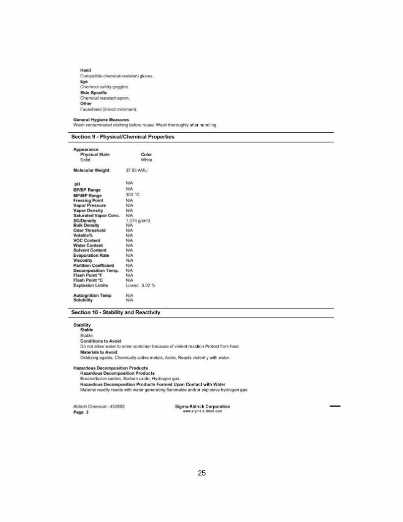
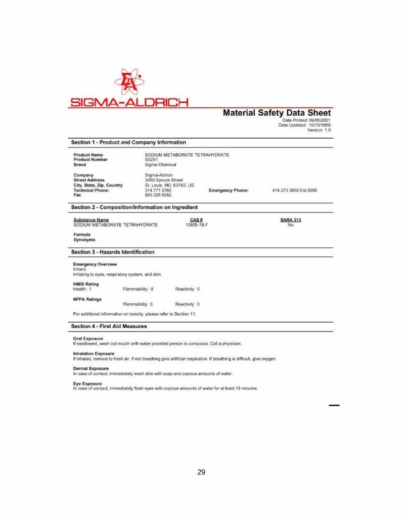
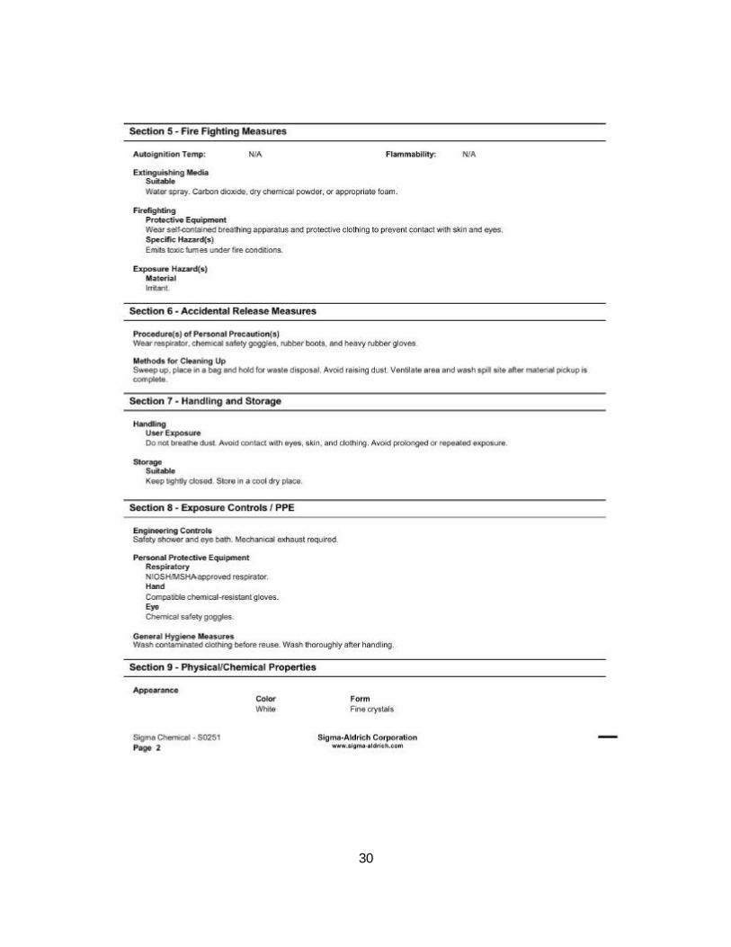
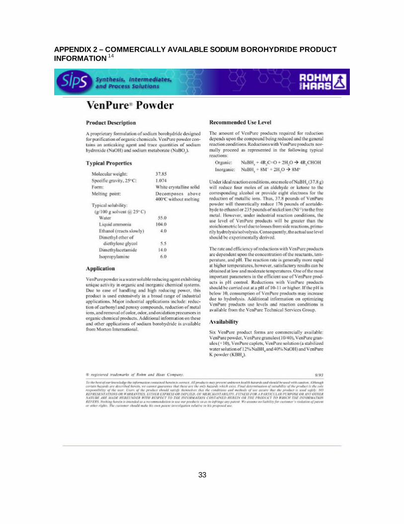
Hydrogen-On-Demand Development at Millennium Cell, Inc. Hydrogen gas has a very low volumetric energy density. Previous solutions to this problem, including high-pressure storage, storage using metal hydride adsorption5, and liquefaction, all have significant drawbacks. Researchers have spent considerable effort to identify a method to overcome the safety, weight, and volumetric limitations of these storage mechanisms for all uses.6,7. The premise of the project required the use of a catalyst enhanced storage process. It was proposed that a sodium borohydride system be used as a medium for the storage, transportation, and generation of hydrogen gas, see Appendix 1 for Material Safety Data Sheet (MSDS) information. The stoichiometric hydrolysis reaction of sodium borohydride (NaBH4) can generate 4 mols of H2 gas per mol of NaBH4.8 Sodium borohydride powder is stable in dry air, but will undergo hydrolysis with acidic or neutral pH water to generate hydrogen gas. Sodium borohydride is incompatible chemically with heat, strong oxidizing agents, chemically active metals, and acids. See Appendix 2 – Commercially Available Sodium Borohydride Product Information for more information on sodium borohydride powders available from Rohm and Haas. The Rohm and Haas literature has summarized the properties, handling, and disposal of sodium borohydride powder. The powder form of sodium borohydride is considered flammable as the hydrogen generated from hydrolysis or thermal decomposition will ignite in the presence of free flame. The most likely route of exposure to sodium borohydride powder is via skin contact, therefore lab protective gear is recommended including goggles and face shield, lab coat and apron, vent hood, etc. for an exact description and safety precautions of sodium borohydride in the powder form (please Appendix 1 - MSDS and Product Information 13 for MSDS information). The acute dermal LD50 of sodium Borohydride is 4-8 g/kg 10 (equivalent to 272 to 544 g for a 150 lb person). The current cost of sodium borohydride is $40/kg however if it were to become more widely used for hydrogen production, its cost would reduce and it could become economically competitive with fossil fuels8. Over time, non-stabilized solutions of sodium borohydride will decompose and off-gas hydrogen. This rapid reaction makes raw sodium borohydride an infeasible fuel solution, and continuous production of hydrogen gas is a safety issue. Alkaline solutions of sodium hydroxide are stable9 and 10 as the rate of the hydrolysis reaction is slowed with increasing pH. In fact, a solution of sodium borohydride and sodium hydroxide is commercially available for use in the paper industry and is stable for months. Concentrations as low as 1 percent sodium hydroxide are enough to prevent hydrolysis and to allow the use of aqueous sodium borohydride as a viable fuel solution. For use in the Hydrogen-On-Demand generator, a 20 percent by weight solution of sodium borohydride is stabilized by 1 percent by weight sodium hydroxide. Therefore the fuel composition by weight is 20 percent sodium borohydride (NaBH4), one percent sodium
10
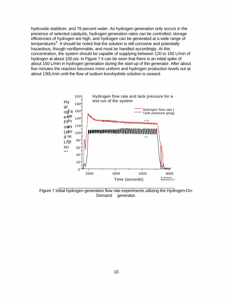
hydroxide stabilizer, and 79 percent water. As hydrogen generation only occurs in the presence of selected catalysts, hydrogen generation rates can be controlled, storage efficiencies of hydrogen are high, and hydrogen can be generated at a wide range of temperatures8. It should be noted that the solution is still corrosive and potentially hazardous, though nonflammable, and must be handled accordingly. At this concentration, the system should be capable of supplying between 120 to 150 L/min of hydrogen at about 100 psi. In Figure 7 it can be seen that there is an initial spike of about 150 L/min in hydrogen generation during the start-up of the generator. After about five minutes the reaction becomes more uniform and hydrogen production levels out at about 130L/min until the flow of sodium borohydride solution is ceased.
2000 4000 6000 8000 0
20
40
60
80
100
120
140
160
180
200
Tank
H2 flow rate
R. Mohring Millennium Cell
Hydrogen flow rate and tank pressure for a test run of the system
Hydrogen flow rate (SLM) Tank pressure (psig)
Hydrogen Flow (std L/min)
Tank Pressure (psig
Time (seconds)
Figure 7 Initial hydrogen generation flow rate experiments utilizing the Hydrogen-On-
Demand generator.
11
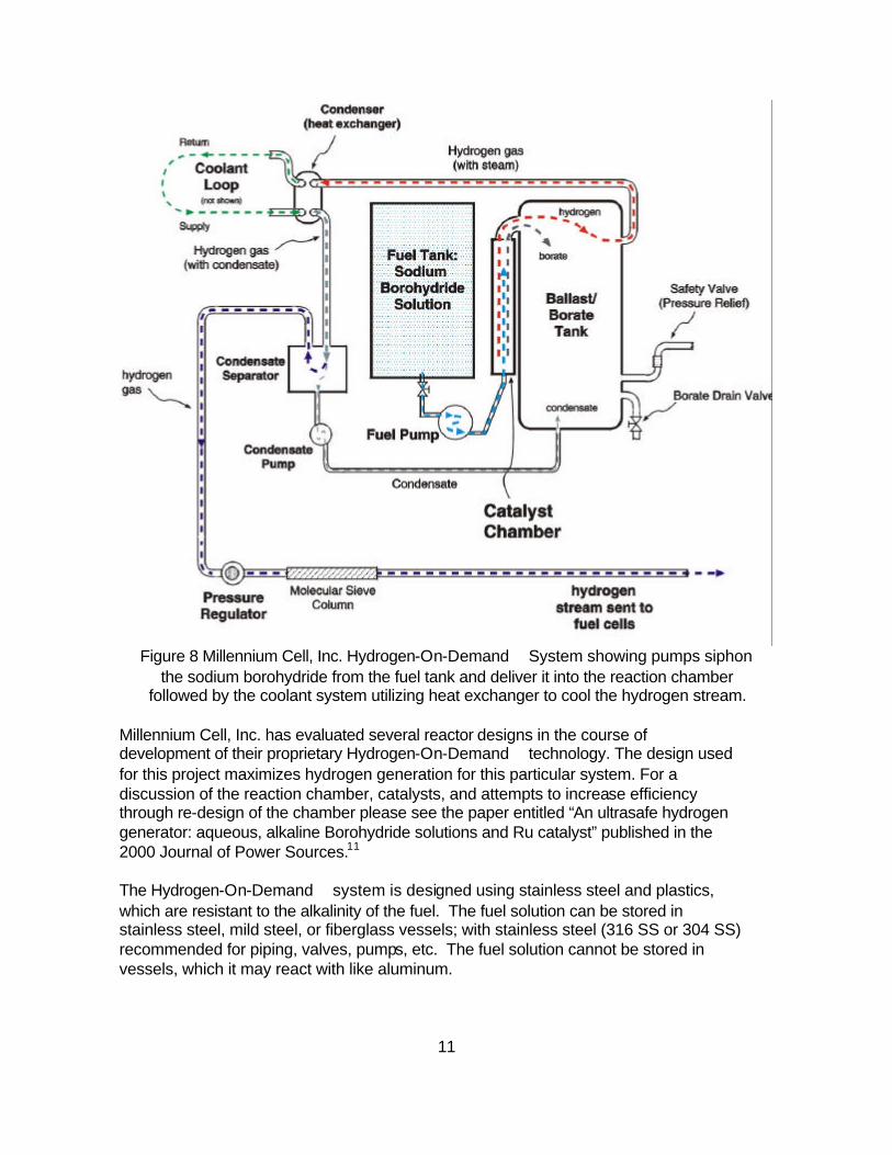
Figure 8 Millennium Cell, Inc. Hydrogen-On-Demand System showing pumps siphon
the sodium borohydride from the fuel tank and deliver it into the reaction chamber followed by the coolant system utilizing heat exchanger to cool the hydrogen stream.
Millennium Cell, Inc. has evaluated several reactor designs in the course of development of their proprietary Hydrogen-On-Demand technology. The design used for this project maximizes hydrogen generation for this particular system. For a discussion of the reaction chamber, catalysts, and attempts to increase efficiency through re-design of the chamber please see the paper entitled “An ultrasafe hydrogen generator: aqueous, alkaline Borohydride solutions and Ru catalyst” published in the 2000 Journal of Power Sources.11 The Hydrogen-On-Demand system is designed using stainless steel and plastics, which are resistant to the alkalinity of the fuel. The fuel solution can be stored in stainless steel, mild steel, or fiberglass vessels; with stainless steel (316 SS or 304 SS) recommended for piping, valves, pumps, etc. The fuel solution cannot be stored in vessels, which it may react with like aluminum.

12
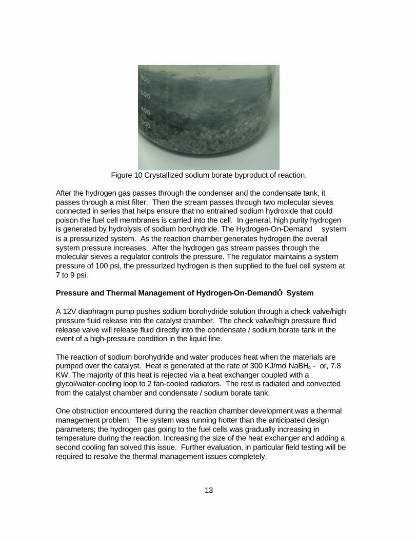
In the Hydrogen-On-Demand system as shown in Figure 8, a solution of sodium borohydride in water is stored in a plastic fuel tank see Figure 9. Pumps siphon the sodium borohydride solution from the fuel tank to the reaction chamber. Millennium Cell’s proprietary catalyst is contained within the reaction chamber; sodium borohydride solution flows over but does not disassociate the catalyst. As the solution flows over the catalyst, hydrolysis occurs and hydrogen gas is released; the byproducts of this reaction are water, heat, sodium borate, sodium hydroxide, and of course hydrogen. The spent fuel, sodium borate, as shown in Figure 10 and gaseous hydrogen from the reactor passes into a pressurized separation/buffer storage tank shown in Figure 9. This tank can hold +/- 32 gallons. The hydrogen and the water in the form of steam pass from the separation/buffer storage tank into the condenser. The steam is converted to liquid water and any residual sodium borate and sodium hydroxide are solidified as the water collects in the condensate reservoir where it can be removed. In regards to freezing of the solution, all aqueous salt solutions exhibit the colligative property of freezing point depression. As the fuel solution is a solution of two inorganic salts – sodium hydroxide and sodium borohydride – both will have an effect on the freezing point of water. This effect is similar to the use of ethylene glycol as antifreeze. The fuel solution should not freeze at temperatures above –30oC. In the condensate / sodium borate tank the spent fuel sodium borate is collected. This material must be drained and disposed of after each run of the generator. The drain valve on the bottom of the tank is opened and the material is gravity drained from the tank. Sodium borate is known to crystallize as demonstrated in Figure 10 and could potentially cause clogging issues within the system, though this has not been observed to date. After the tank is drained the entire system is flushed with clean warm water to remove the sodium borate spent fuel. Sodium borate is not considered to be toxic, and can be disposed of down the drain to the sewer in aqueous solutions in accordance with the MSDS and all federal, state and local environmental regulations.13 See Appendix 1 for the full MSDS information on the spent fuel sodium borate. There is currently research underway by other organizations into methods to recycle the sodium borate product back into sodium borohydride to make the generation system viable for the market.
Figure 9 Spent fuel condensate / sodium borate tank (left) and fuel tank (right).
13
Figure 10 Crystallized sodium borate byproduct of reaction.
After the hydrogen gas passes through the condenser and the condensate tank, it passes through a mist filter. Then the stream passes through two molecular sieves connected in series that helps ensure that no entrained sodium hydroxide that could poison the fuel cell membranes is carried into the cell. In general, high purity hydrogen is generated by hydrolysis of sodium borohydride. The Hydrogen-On-Demand system is a pressurized system. As the reaction chamber generates hydrogen the overall system pressure increases. After the hydrogen gas stream passes through the molecular sieves a regulator controls the pressure. The regulator maintains a system pressure of 100 psi, the pressurized hydrogen is then supplied to the fuel cell system at 7 to 9 psi. Pressure and Thermal Management of Hydrogen-On-Demand System A 12V diaphragm pump pushes sodium borohydride solution through a check valve/high pressure fluid release into the catalyst chamber. The check valve/high pressure fluid release valve will release fluid directly into the condensate / sodium borate tank in the event of a high-pressure condition in the liquid line. The reaction of sodium borohydride and water produces heat when the materials are pumped over the catalyst. Heat is generated at the rate of 300 KJ/mol NaBH4 - or, 7.8 KW. The majority of this heat is rejected via a heat exchanger coupled with a glycol/water-cooling loop to 2 fan-cooled radiators. The rest is radiated and convected from the catalyst chamber and condensate / sodium borate tank. One obstruction encountered during the reaction chamber development was a thermal management problem. The system was running hotter than the anticipated design parameters; the hydrogen gas going to the fuel cells was gradually increasing in temperature during the reaction. Increasing the size of the heat exchanger and adding a second cooling fan solved this issue. Further evaluation, in particular field testing will be required to resolve the thermal management issues completely.
14
The Compressed Gas Association Guidelines for hydrogen were used for guidance in designing the system. The tank and its fittings are welded and pressure tested. The tank is steel. Piping and fittings in the system from the check valve onward are stainless steel with threaded fittings (with high-temp Teflon thread sealant). The operating temperature is 130oC to 170oC the tank temperature rating is 300oC. The entire system is pressure tested overnight on hydrogen to 200 psi and monitored for any loss of pressure. The normal operating pressure is 100 psi with the pressure relief setting at 150 psi. In addition to this fluid pressure relief valve, there is a solenoid-operated pressure-relief valve and a backup mechanical pressure relief valve at the exit to the condensate / sodium borate tank. A short section of high-pressure stainless steel braided tubing on the hydrogen outlet provides strain relief to maintain the integrity of the hydrogen piping. The net output of the fuel cells is 11.7 kW. Of that net voltage there are approximately 2 to 2.5 kW of system loads and efficiency losses. The boost converters are approximately 96 percent efficient therefore nearly 500 watts is lost in the converters. The compressor is one of the most significant loads in the fuel cell system at roughly 800 watts. One of the other most noteworthy loads is the cooling fans at about 500 watts. There are several additional system component loads like miscellaneous pumps and blowers among others that also draw down the net power estimated at another 300 watts. After taking into consideration all these loads the total usable power supplied to the motor is on the order of 9.6 kW. All of the main electrical systems were selected to reduce the power loss and loads as much as possible. The fuel cell system consists of two stacks with an anticipated net out of 5.85 kW each, or 11.7 kW total at 90Amps and 120V to 130V. The differential between gross and net output is a result of losses and other drains such as various electrical systems for example pumps, fans, and blowers which are part of the fuel cell system. Each fuel cell stack generates power at 60-65 V DC nominal, and they are connected in series for 120-139 V DC output. The 120-volt power from the fuel cell system is converted to power in the range of 300 V DC to approximately 350 V DC . It was expected that the two fuel cells would operate in series to produce about 14kW gross power however a majority of the system losses occur within the fuel cells, thus the projected design net output of the fuel cells was expected to be about 10kW. After the initial bench testing of the fuel cell stacks it was found that the stacks have a net output 11.7kW including the electrical loss. A comparison is shown in Table 1.
15
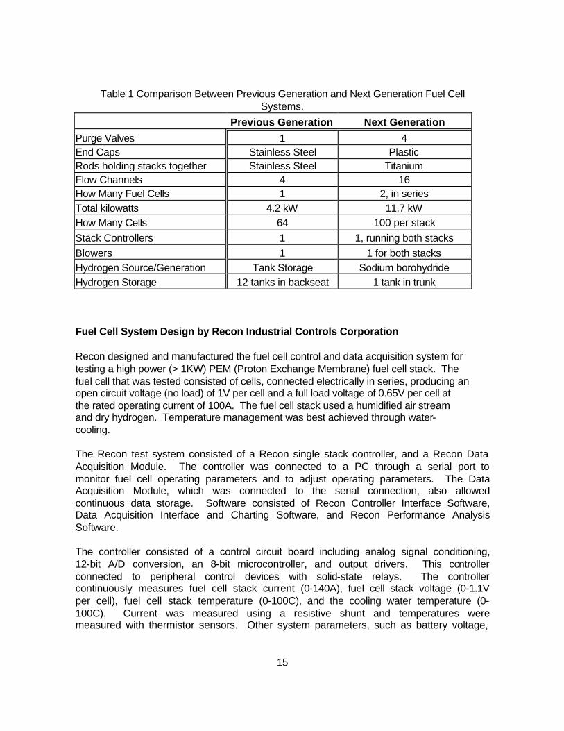
Table 1 Comparison Between Previous Generation and Next Generation Fuel Cell Systems.
Previous Generation Next Generation
Purge Valves 1 4 End Caps Stainless Steel Plastic Rods holding stacks together Stainless Steel Titanium Flow Channels 4 16 How Many Fuel Cells 1 2, in series Total kilowatts 4.2 kW 11.7 kW How Many Cells 64 100 per stack Stack Controllers 1 1, running both stacks Blowers 1 1 for both stacks Hydrogen Source/Generation Tank Storage Sodium borohydride Hydrogen Storage 12 tanks in backseat 1 tank in trunk Fuel Cell System Design by Recon Industrial Controls Corporation Recon designed and manufactured the fuel cell control and data acquisition system for testing a high power (> 1KW) PEM (Proton Exchange Membrane) fuel cell stack. The fuel cell that was tested consisted of cells, connected electrically in series, producing an open circuit voltage (no load) of 1V per cell and a full load voltage of 0.65V per cell at the rated operating current of 100A. The fuel cell stack used a humidified air stream and dry hydrogen. Temperature management was best achieved through water-cooling. The Recon test system consisted of a Recon single stack controller, and a Recon Data Acquisition Module. The controller was connected to a PC through a serial port to monitor fuel cell operating parameters and to adjust operating parameters. The Data Acquisition Module, which was connected to the serial connection, also allowed continuous data storage. Software consisted of Recon Controller Interface Software, Data Acquisition Interface and Charting Software, and Recon Performance Analysis Software. The controller consisted of a control circuit board including analog signal conditioning, 12-bit A/D conversion, an 8-bit microcontroller, and output drivers. This controller connected to peripheral control devices with solid-state relays. The controller continuously measures fuel cell stack current (0-140A), fuel cell stack voltage (0-1.1V per cell), fuel cell stack temperature (0-100C), and the cooling water temperature (0-100C). Current was measured using a resistive shunt and temperatures were measured with thermistor sensors. Other system parameters, such as battery voltage,
16
were also measured. Output devices controlled included a DC motor/compressor, water pump, cooling fans, hydrogen shutoff and purge valves, and a water-recycling pump. One primary function of the controller is to provide the proper airflow to meet the stoicheometric oxygen needs based on fuel cell stack current. The controller provides a nonlinear control function to adjust the compressor motor voltage via PWM (Pulse Width Modulation) duty cycle regulation according to changes in fuel cell stack current. The period and duration of hydrogen purging is also controlled according to current to discharge water and any hydrogen impurities that collect on the cathodic (hydrogen) side. A control loop also runs based on fuel cell stack and cooling water temperature to control water pump and cooling fan speed to maintain proper operating conditions.
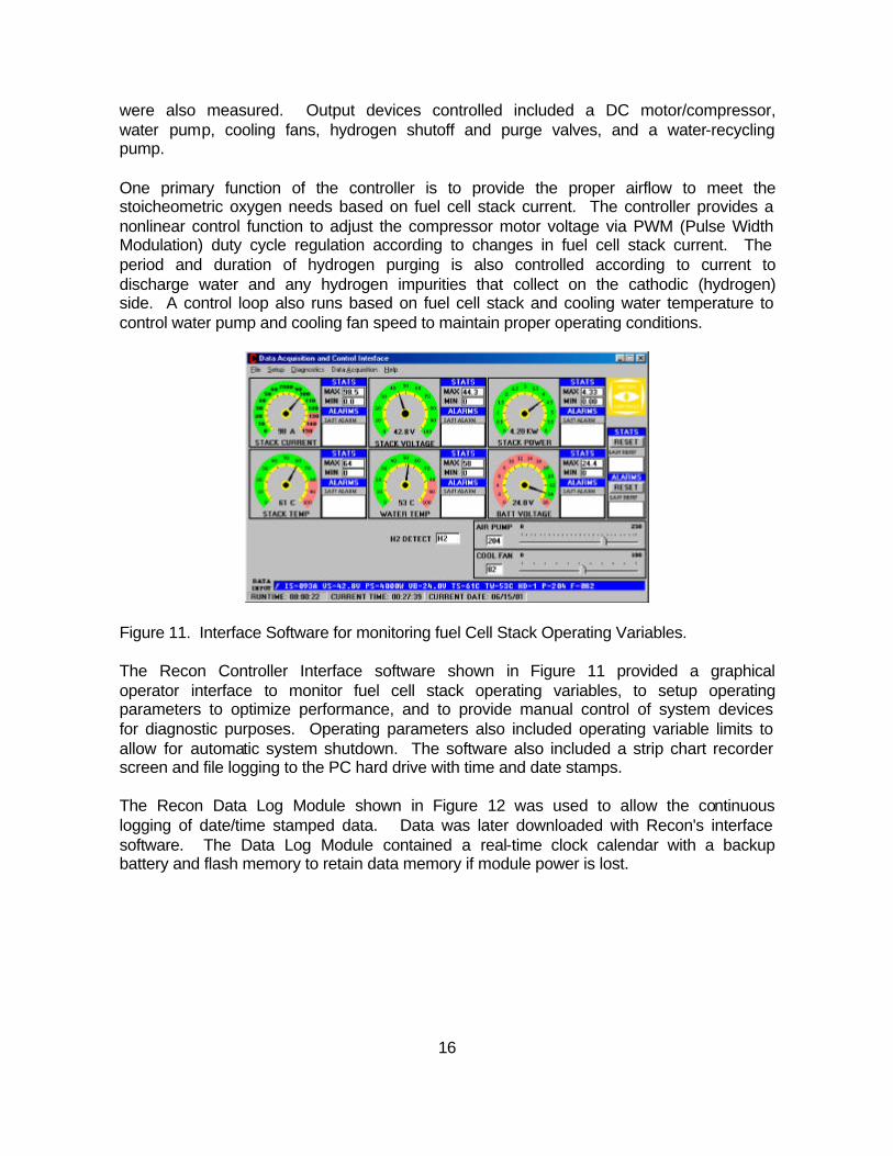
Figure 11. Interface Software for monitoring fuel Cell Stack Operating Variables. The Recon Controller Interface software shown in Figure 11 provided a graphical operator interface to monitor fuel cell stack operating variables, to setup operating parameters to optimize performance, and to provide manual control of system devices for diagnostic purposes. Operating parameters also included operating variable limits to allow for automatic system shutdown. The software also included a strip chart recorder screen and file logging to the PC hard drive with time and date stamps. The Recon Data Log Module shown in Figure 12 was used to allow the continuous logging of date/time stamped data. Data was later downloaded with Recon's interface software. The Data Log Module contained a real-time clock calendar with a backup battery and flash memory to retain data memory if module power is lost.

17
Figure 12. Data Log Module for the continuous logging of date/time stamped data.
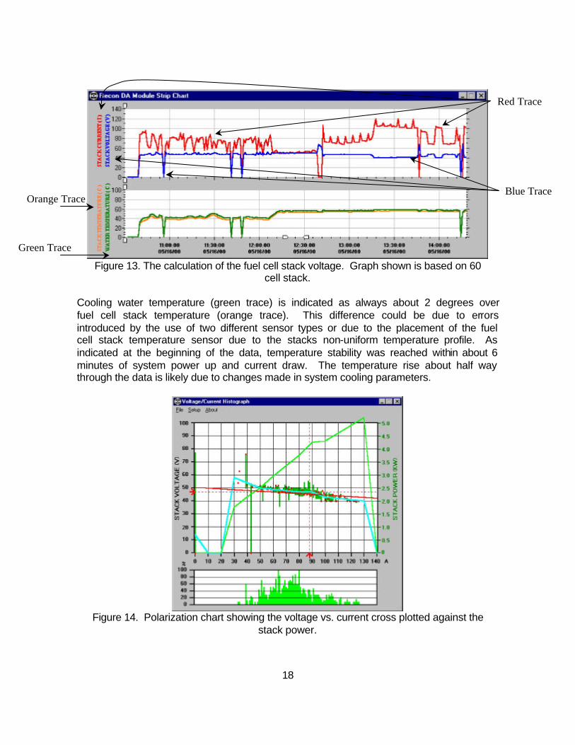
The module was setup to log samples of controller-acquired data with a sample period of 1 minute. The downloaded data was saved in PC memory to then be displayed on the included strip chart or exported in a text format that is easily imported into Excel or into Recon Fuel Cell Analyzer software. The included stripchart shown in Figure 13 allowed data to be viewed graphically. The X-axis displays the time and date of the acquired samples and the Y-axis of the top chart corresponds to fuel cell stack current (red trace) and fuel cell stack voltage (blue trace). The Y-axis of the bottom chart corresponds to cooling water temperature (green trace) and fuel cell stack temperature (orange trace). Zoom and pan functions allowed both X- and Y- axis to be expanded and to allow scrolling through data. The section of data shown represents fuel cell operation during one day of testing. The times at which all 4 traces are at the zero baseline indicates times at which the system was turned off, possibly for control parameter changes. There are 2 occurrences of zero stack current (red trace) with no corresponding zeroing of temperature (green and orange traces). At these times the system was running, but no power (zero load) was being drawn from the stack. This allowed the fuel cell stack voltage to reach its open circuit voltage of about 0.1 volts per cell as indicated by the fuel cell stack voltage (blue trace) at the times of zero fuel cell stack current. Due to the internal impedance of the fuel cell stack, current increases cause a corresponding decrease in voltage.
18
Figure 13. The calculation of the fuel cell stack voltage. Graph shown is based on 60
cell stack. Cooling water temperature (green trace) is indicated as always about 2 degrees over fuel cell stack temperature (orange trace). This difference could be due to errors introduced by the use of two different sensor types or due to the placement of the fuel cell stack temperature sensor due to the stacks non-uniform temperature profile. As indicated at the beginning of the data, temperature stability was reached within about 6 minutes of system power up and current draw. The temperature rise about half way through the data is likely due to changes made in system cooling parameters.
Figure 14. Polarization chart showing the voltage vs. current cross plotted against the
stack power.
Blue Trace
Red Trace
Orange Trace
Green Trace

19
The data file created by the Data Log Module interface software was then imported into the Recon Fuel Cell Performance Analyzer software, which creates a polarization chart (voltage vs. current) and current histogram and is shown in Figure 14. The X-axis represents the fuel cell stack current, from zero current (no load) to high currents (full rated load and over) for both the top polarization chart and the bottom current histogram. For every data sample logged from the controller the fuel cell stack voltage point is placed on the chart at the corresponding current position. The vertical bars on the lower graph indicate low to high ranges of voltages measured for particular currents, due to varying fuel cell performance (most influenced by membrane humidity and temperature changes). The blue trace follows the averaged voltage values measured and the green trace follows the average fuel cell stack power values calculated from the measured currents and voltages. The straight red line is a best-fit line whose slope and position is calculated by means of a least squared method to provide an average of fuel cell stack impedance.12 Estimated Ability Calculations To begin with, an overall efficiency must be calculated. During design meeting estimates of other systems overall efficiencies were substituted for an actual value. This practice continued until the initial bench tests were performed. The efficiency was measured in the lab using several system characteristics. This of course is a rather conservative estimate and was better estimated after actual testing. To calculate the projected output as a result of the hydrogen generator working with the fuel cells requires several steps. STEP 1 For use in the Hydrogen-On-Demand generator, a 20 percent by weight solution of sodium borohydride is stabilized by 1 percent by weight sodium hydroxide. Therefore the fuel composition by weight is 20 percent sodium borohydride (NaBH4), one percent sodium hydroxide stabilizer, and 79 percent water. At this concentration, the system is capable of supplying hydrogen at about 520 liters of hydrogen gas per liter of fuel. STEP 2 The fuel tank can hold up to 32 gallons (121.1 liters) of the 20 percent sodium borohydride (NaBH4) fuel solution. Multiplying the hydrogen generation rate of 520 L/min by the storage capacity of the fuel solution of 121.1 L yields the total hydrogen supplied by the generator of 62,972 liters of hydrogen. STEP 3 The fuel cell system requires an average hydrogen flow of 4.9 scfm (138.8 L/min). The flow rate will also vary with time; flow will increase when the fuel cell system purges. The actual flow rate will vary proportionally with the load. Dividing the net hydrogen from the generator 62,972L by the fuel cell usage of 138.8 L/min it results in a total runtime for the fuel cells of 454 minutes or approximately 7.57 hours.

20
Therefore for one tank of 20 percent sodium borohydride (NaBH4) fuel solution the fuel cells can operate continuously for 7.57 hours. STEP 4 The net output of the fuel cells is 11.7 kW. Of that net voltage there are approximately 2 to 2.5 kW of system loads and efficiency losses. After taking into consideration all these loads the total usable power supplied to the motor is on the order of 9.6 kW. Multiplying the total continuous runtime of 7.57 hrs by the net output (after loads and efficiency losses) to the motor of 9.6 kW, the result is 72,672 watt-hours. Consumption rates and run times The hydrogen generator has an average generation rate of about 130 L/min until the flow of sodium borohydride solution is ceased. This 130 L/min is slightly less than the demand from the fuel cell of 138.8 L/min. The generator produces about 520 L hydrogen per liter of fuel thus at 150 L of hydrogen per minute the generator can run continuously on the 121.1 L fuel storage for 8.07 hours. If the fuel cells ran continuously they would consume this amount of hydrogen in 7.57 hours. Thus in order for the generator to produce all of the hydrogen for use in the fuel cells there will be a delay of approximately 0.5 hours. This offset can be easily accommodated in a completely integrated system through the usage of a battery pack. CONCLUSIONS The two fuel cells that were used are larger than the one from the previous generation. However, several subsystems have been combined to reduce redundancy, instead of having true parallel system components such as air blowers, controllers, humidifiers, and heat exchangers they have been increased in size and the fuel cells linked in a series system. For example only one blower is used for both stacks. Also a new custom built fully automated controller monitors all fuel cell functions as well as optimizing flow rates and purge cycles thus increasing overall system efficiency. The control board is a critical component and is responsible for varying the speed of the air compressor and for continuously performing safety checks of the voltage and temperature of the fuel cell stacks. Finally light weight materials have been used to not only reduce the weight of the fuel cell stacks but also the size. The original design of the fuel cells used many stainless steel components. The fuel cell stainless steel rods and end plates were replaced with titanium rods and plastic end plates. The plates that were used inside of previous generation fuel cell were made of stainless steel. The net weight savings per fuel cell stack was approximately 50 pounds. The result of the upgrades is that each fuel cell stack is now 10" X 12" X 24" and weighs only 75 pounds. A comparison between the two systems is shown in Table 1. Safety in handling of the sodium borohydride should not be a problem if the necessary precautions are taken following the MSDS sheets in Appendix 1. The solution of the sodium borohydride in water can achieve hydrogen production rates between 120 to 150 L/min at about 100 psi. The products of power production will be pure water,

21
hydrogen gas, and sodium borate. It is possible to recycle the spent fuel sodium borate back into sodium borohydride, however this process is outside the scope of this project. Future research may show an inexpensive process to regenerate sodium borohydride from sodium borate, which would be a significant step in demonstrating this fuel as a renewable resource. Regulatory controls will make sure pressure within the system not exceed safe levels. It was shown in this report that the output of the generator comes close ( ~.5 hour ) to equaling the fuel cell output. Potential refinements of the system include possibly lowering the weight of the entire system or possibly applying the system to a technology that would reasonably benefit from its use. While it is clear that the objectives of this project have been met, this project has opened many broader issues as to the uses of this apparatus. Numerous projects could stem from this research. There are also technological advancements that will occur in generations to come.

22
REFERENCES CITED 1 Maher and Szary; NJ Fuel Cell Hybrid Electric Vehicle (HEV) Year II Project Proposal, Rutgers/CAIT submitted to NJDOT November 17, 1999 2 Technology Validation Plan, U.S. Department of Energy, http://www.eren.doe.gov/hydrogen/program.html, November, 1998, p. 14. 3 The Fuel Cell, United Stated Department of Transportation, 1999. http://www.fta.dot.gov/library/technology/dotweb.htm 4 Multicomponent Transport in Porous Electrodes of Proton Exchange Membrane Fuel Cells using the Interdigitated Gas Distributors, J Yi, T. Van Nguyen. Journal of the Society. V 146 n 1, 1999. 5 Sandrock, Application of Hydrides in Hydrogen Energy Systems, Kluwer Academic Publishers, Netherlands, 1995 6 Overview of Storage Development DOE Hydrogen Program George Thomas Sandia National Laboratories Livermore, CA Hydrogen Program Review San Ramon, CA May 9-11, 2000 Proceedings of the 2000 DOE Hydrogen Program Review 7 Analysis of Residential Fuel Cell Systems & PNGV Fuel Cell Vehicles, C.E. (Sandy) Thomas, B.D. James and F.D. Lomax, Jr., Directed Technologies, Inc. Proceedings of the 2000 DOE Hydrogen Program Review NREL/CP-570-28890 8 A Novel Catalytic Process for Generating Hydrogen Gas from Aqueous Borohydride Solutions Amendola, Binder, Kelly, and Petillo; Advances in Hydrogen Energy, Kluwer Academic/Plenum Publishers, 2000 9 US Patent 2,970,114, R. W. Bragdon 10 "Safety and Handling of Sodium Borohydride", Il Prodotto Chimico, September 1988, Vol. 29, p 39-41 11 An ultrasafe hydrogen generator: aqueous, alkaline borohydride solutions and Ru catalyst, Steven C. Amendola, Stefanie L. Sharp-Goldman, M. Saleem Janjua, Michael T. Kelly, Phillip J. Petillo, and Michael Binder, Millennium Cell, Inc., Journal of Power Sources 85 (2000) 186-189 12 Reference Information Provided by Joe Barbetta 6/27/01. 13 Sigma Chemical Company, Material Safety Data Sheets, Copyrighted information was used by permission of Sigma-Aldrich Co, June 2001 14 Rohm and Haas Literature, Data Sheets for VenPure Powder, 9/93
23
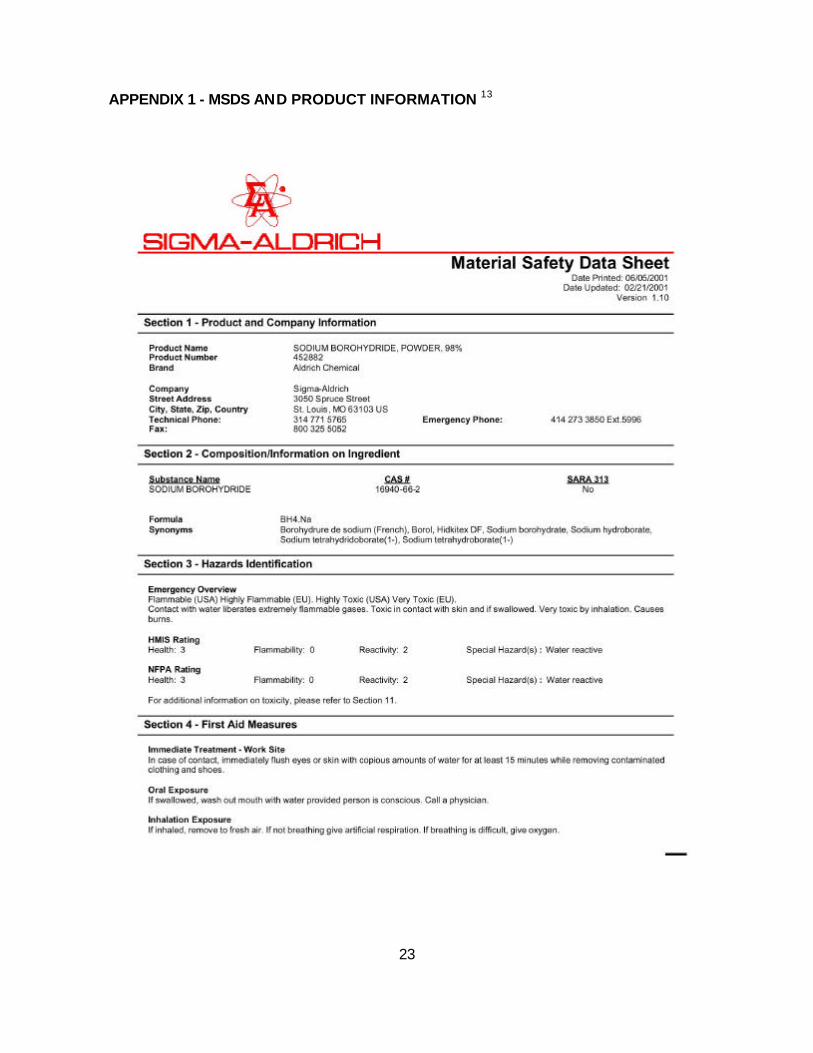
APPENDIX 1 - MSDS AND PRODUCT INFORMATION 13

24
25

26

27

28
29
30

31

32
33
APPENDIX 2 – COMMERCIALLY AVAILABLE SODIUM BOROHYDRIDE PRODUCT INFORMATION 14

34
35
APPENDIX 3 - ADDITIONAL TECHNICAL PICTORIAL
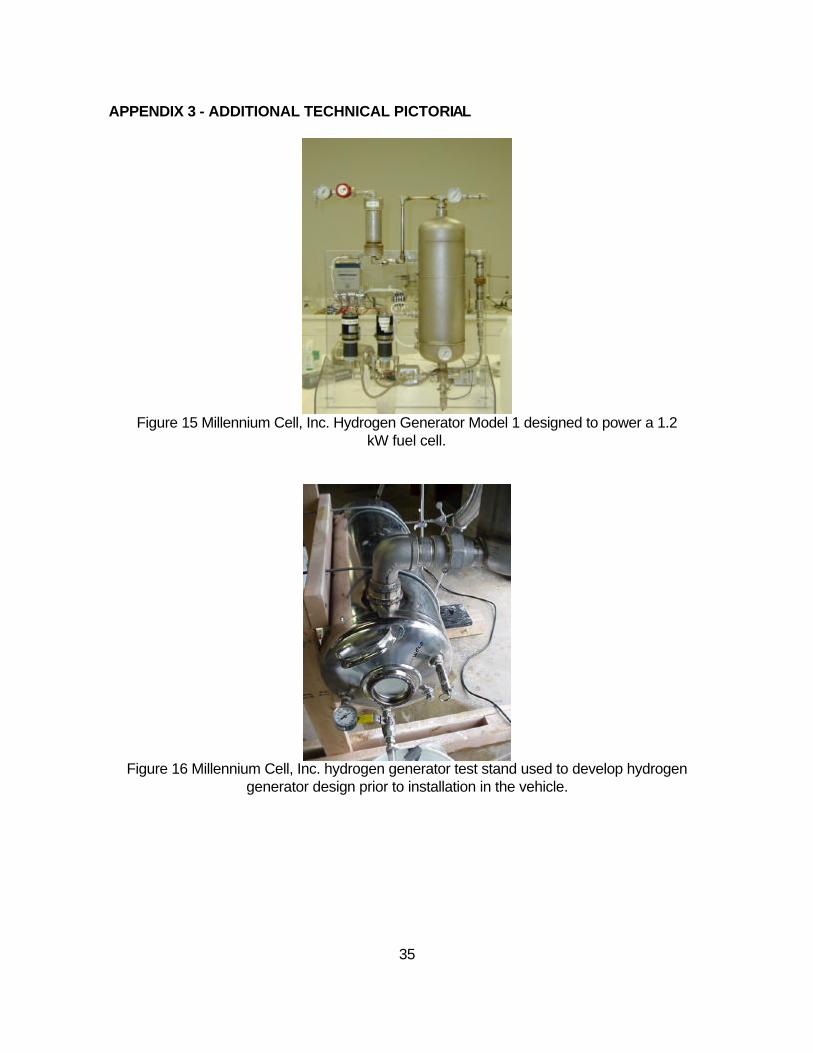
Figure 15 Millennium Cell, Inc. Hydrogen Generator Model 1 designed to power a 1.2
kW fuel cell.
Figure 16 Millennium Cell, Inc. hydrogen generator test stand used to develop hydrogen
generator design prior to installation in the vehicle.

36
Figure 17 Hydrogen generator test stand condenser water reclamation tank used to
develop hydrogen generator design prior to installation in the vehicle.
Figure 18 Fuel cell air compressor assembly.
Figure 19 Custom stainless steel radiator to cool fuel cell system.

37
Figure 20 Two 7 kW (gross) fuel cell stacks installed in a vehicle.
Figure 21 Schematic of Hydrogen Generation System