Embed Size (px)
Citation preview

BFSD – 1 Revised 01/02/2018
THE FOLLOWING INSTALLATION METHODS ARE INCLUDED IN THIS BOOKLET:
New Construction Installation in Masonry Construction for Block Frame Sliding Doors
These instructions were developed and tested for use with wall systems designed to manage water. These instructions are not to be used with any other construction methods or door frame types. Installation instructions for use with other construction methods or frame types may be obtained from Pella® Corporation, your local Pella retailer or www.installpella.com. Building designs, construction methods, building materials, and site conditions unique to your project may require an installation method different from these instructions and/or additional care. Determining the appropriate installation method is the responsibility of you, your architect, or construction professional.
Full Frame Replacement without Disturbing Brick or Siding for Block Frame Sliding Doors
Pella Installation InstructionsBLOCK FRAME SLIDING DOORS
Always read the Limited Warranty before purchasing or installing Pella® products. By installing this product, you are acknowledging that this Limited Warranty is part of the terms of the sale. Failure to comply with all Pella installation and maintenance instructions may void your Pella product warranty. See written Limited Warranty for details, including exceptions and limitations at pella.com/warranty, or contact Pella Customer Service at 877-473-5527.
© 2018 Pella Corporation Block Frame Booklet
BFSD – 2 Revised 01/02/2018
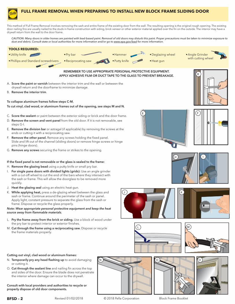
If the fixed panel is not removable or the glass is sealed to the frame:
H. Remove the glazing bead using a putty knife or small pry bar.
I. For single pane doors with divided lights (grids): Use an angle grinder with a cut-off wheel to cut the end of the bars where they intersect with the sash or frame. This will allow the doorglass to be removed more quickly.
J. Heat the glazing seal using an electric heat gun.
K. While applying heat, press a de-glazing wheel between the glass and sash or frame. Continue around the perimeter of the sash or panel. Apply light, constant pressure to separate the glass from the sash or frame. Dispose or recycle the glass properly.
Note: Wear appropriate personal protective equipment and keep the heat source away from flammable materials.
L. Pry the frame away from the brick or siding. Use a block of wood under the pry bar to protect interior or exterior finishes.
M. Cut through the frame using a reciprocating saw. Dispose or recycle the frame materials properly.
This method of Full Frame Removal involves removing the sash and entire frame of the existing door from the wall. The resulting opening is the original rough opening. The existing door nailing fins are usually nailed to the studs in frame construction with siding, brick veneer or other exterior material applied over the fin on the outside. The interior may have a drywall return from the wall to the door frame.
TOOLS REQUIRED:
• Utility knife
• Phillips and Standard screwdrivers
• Pry bar
• Reciprocating saw
• Hammer
• Putty knife
• Deglazing wheel
• Heat gun
• Angle Grinder with cutting wheel
REMEMBER TO USE APPROPRIATE PERSONAL PROTECTIVE EQUIPMENT.APPLY ADHESIVE FILM OR DUCT TAPE TO THE GLASS TO PREVENT BREAKAGE.
CAUTION: Many doors in older homes are painted with lead-based paint. Removal of old doors may disturb this paint. Proper precautions must be taken to minimize exposure to dust and debris. Consult state or local authorities for more information and/or go to www.epa.gov/lead for more information.
A. Score the paint or varnish between the interior trim and the wall or between the drywall return and the doorframe to minimize damage.
B. Remove the interior trim.
To collapse aluminum frames follow steps C-M.
To cut vinyl, clad wood, or aluminum frames out of the opening, see steps M and N.
C. Score the sealant or paint between the exterior siding or brick and the door frame.
D. Remove the screen and vent panel from the old door. If it is not removable, see steps G-I.
E. Remove the division bar or astragal (if applicable) by removing the screws at the ends or cutting it with a reciprocating saw.
F. Remove the other panel. Remove any screws holding the fixed panel. Slide and lift out of the channel (sliding doors) or remove hinge screws or hinge pins (hinge doors).
G. Remove any screws securing the frame or strikes to the opening.
Cutting out vinyl, clad wood or aluminum frames:
N. Temporarily pry any head flashing up to avoid damaging or cutting it.
O. Cut through the sealant line and nailing fin across the top and sides of the door. Ensure the blade does not penetrate the interior where damage can occur to the drywall.
Consult with local providers and authorities to recycle or properly dispose of old door components.
IH
E
J K
L M
N O O
FULL FRAME REMOVAL WHEN PREPARING TO INSTALL NEW BLOCK FRAME SLIDING DOOR
F
B
© 2018 Pella Corporation Block Frame Booklet
BFSD – 3 Revised 01/02/2018
YOU WILL NEED TO SUPPLY: TOOLS REQUIRED:
• Moisture resistant shims/spacers
• Fasteners (see block frame anchor instructions and tables at the end of this booklet)
• Closed cell foam backer rod/sealant backer
• Pella® SmartFlash™ foil backed butyl window and door flashing tape or equivalent
• Low expansion, low pressure polyurethane insulating window and door foam sealant DO NOT use high pressure or latex foams.
• Pella Window and Door Installation Sealant or equivalent high quality, multi-purpose sealant
• Installation Clip Option:
• 6" or 8" installation clips
• #6 x 5/8" corrosion resistant flat head wood screws
• #8 x 1-1/2" corrosion resistant screws or 3/16" x 1-1/2" masonry screws
• Tape measure
• Level
• Square
• Hammer
• Scissors or utility knife
• Small flat blade screwdriver
• Sealant Gun
• Screw Gun with a Phillips Driver bit
• 1/8" Allen wrench
SEALANTSEALANT
INSTALLATION WILL REQUIRE (2) OR MORE PERSONS FOR SAFETY REASONS.
PREPARING FOR BLOCK FRAME SLIDING DOOR INSTALLATION
OTHER CONSTRUCTION MATERIALS MAY BE REQUIRED. READ AND UNDERSTAND THE INSTRUCTIONS AND INSPECT THE WALL CONDITIONS BEFORE YOU BEGIN.
These instructions were developed and tested for use with wall systems designed to manage water. These instructions are not to be used with any other construction methods or doorframe types. Installation instructions for use with other construction methods or frame types may be obtained from Pella® Corporation, your local Pella retailer or www.installpella.com. Building designs, construction methods, building materials, and site conditions unique to your project may require an installation method different from these instructions and/or additional care. Determining the appropriate installation method is the responsibility of you, your architect, or construction professional.
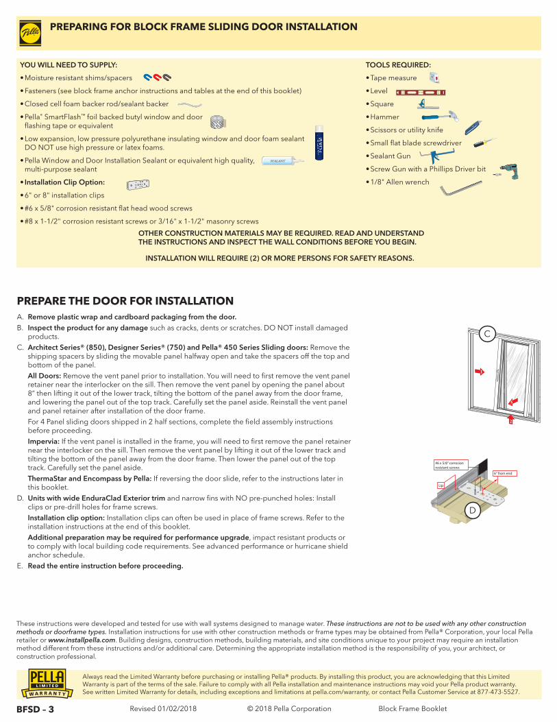
A. Remove plastic wrap and cardboard packaging from the door. B. Inspect the product for any damage such as cracks, dents or scratches. DO NOT install damaged
products. C. Architect Series® (850), Designer Series® (750) and Pella® 450 Series Sliding doors: Remove the
shipping spacers by sliding the movable panel halfway open and take the spacers off the top and bottom of the panel.
All Doors: Remove the vent panel prior to installation. You will need to first remove the vent panel retainer near the interlocker on the sill. Then remove the vent panel by opening the panel about 8” then lifting it out of the lower track, tilting the bottom of the panel away from the door frame, and lowering the panel out of the top track. Carefully set the panel aside. Reinstall the vent panel and panel retainer after installation of the door frame.
For 4 Panel sliding doors shipped in 2 half sections, complete the field assembly instructions before proceeding.
Impervia: If the vent panel is installed in the frame, you will need to first remove the panel retainer near the interlocker on the sill. Then remove the vent panel by lifting it out of the lower track and tilting the bottom of the panel away from the door frame. Then lower the panel out of the top track. Carefully set the panel aside.
ThermaStar and Encompass by Pella: If reversing the door slide, refer to the instructions later in this booklet.
D. Units with wide EnduraClad Exterior trim and narrow fins with NO pre-punched holes: Install clips or pre-drill holes for frame screws.
Installation clip option: Installation clips can often be used in place of frame screws. Refer to the installation instructions at the end of this booklet.
Additional preparation may be required for performance upgrade, impact resistant products or to comply with local building code requirements. See advanced performance or hurricane shield anchor schedule.
E. Read the entire instruction before proceeding.
PREPARE THE DOOR FOR INSTALLATION
1
3
2
6“ from end
Lip
#6 x 5/8” corrosionresistant screws
D
C
Always read the Limited Warranty before purchasing or installing Pella® products. By installing this product, you are acknowledging that this Limited Warranty is part of the terms of the sale. Failure to comply with all Pella installation and maintenance instructions may void your Pella product warranty. See written Limited Warranty for details, including exceptions and limitations at pella.com/warranty, or contact Pella Customer Service at 877-473-5527.
© 2018 Pella Corporation Block Frame Booklet
BFSD – 4 Revised 01/02/2018
1 PREPARE THE OPENINGREMEMBER TO USE APPROPRIATE PERSONAL PROTECTIVE EQUIPMENT.
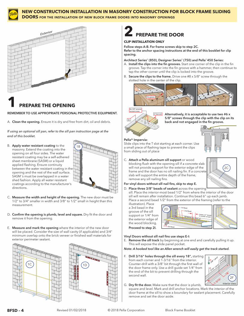
A. Clean the opening. Ensure it is dry and free from dirt, oil and debris.
If using an optional sill pan, refer to the sill pan instruction page at theend of this booklet.
B. Apply water resistant coating to the masonry. Extend the coating into the opening on all four sides. The water resistant coating may be a self-adhered sheet membrane (SASM) or a liquid applied flashing. Ensure continuity between the water resistant coating in the opening and the rest of the wall surface. SASM ’s must be overlapped in a water shed fashion. Apply all water resistant coatings according to the manufacturer’s directions.
C. Measure the width and height of the opening. The new door must be 1/2" to 3/4" smaller in width and 3/8" to 1/2" small in height than this measurement.
D. Confirm the opening is plumb, level and square. Dry fit the door and remove it from the opening.
E. Measure and mark the opening where the interior of the new door will be placed. Consider the size of wall cavity (if applicable) and 3/4" minimum overlap onto the brick veneer or finished wall materials for exterior perimeter sealant.
NEW CONSTRUCTION INSTALLATION IN MASONRY CONSTRUCTION FOR BLOCK FRAME SLIDING DOORS for the installation of new block frame doors into masonry openings
6“ from end
Lip
#6 x 5/8” corrosionresistant screws
Fin groove
CLIP INSTALLATION ONLY
Follow steps A-B. For frame screws skip to step 2C.Refer to the anchor spacing instructions at the end of this booklet for clip spacing.
1B
1C 1D
2 PREPARE THE DOOR
Architect Series® (850), Designer Series® (750) and Pella® 450 Series:A. Install the clips into the fin grooves. Start one corner of the clip in the fin
groove. Tap the corner into the fin groove with a hammer, then continue to tap the other corner until the clip is locked into the groove.
B. Secure the clips to the frame. Drive one #8 x 5/8" screw through the slotted hole in the center of the clip.
Alternatively, it is acceptable to use two #6 x 5/8" screws through the clip with the clip on its back and not engaged in the fin groove.
Exterior
Exterior
Pella® Impervia: Slide clips into the T slot starting at each corner. Use a small piece of flashing tape to prevent the clips from sliding out of place
C. Attach a Pella aluminum sill support or wood blocking flush with the opening sill if a concrete slab will not provide support for the exterior edge of the frame and the door has no sill nailing fin. If a concrete slab will support the entire depth of the frame, remove any sill nailing fins.
For vinyl doors without sill nail fins, skip to step E.D. Place three 3/8" beads of sealant across the opening
sill. Place the interior-most bead 1/2" from where the interior of the door sill will remain after installation. Continue this bead 6" up each jamb. Place a second bead 1/2" from the exterior of the framing (refer to the illustration). Place a 3rd bead in the groove of the sill support or 1/4" from the exterior edge of the wood blocking.
Proceed to step 2I.
Vinyl Doors without sill nail fins use steps E-I:E. Remove the sill track by beginning at one end and carefully pulling it up.
This will expose the slide panel pocket.Note: A hooked tool like an Allen wrench will easily get the track started.
F. Drill 3/16" holes through the sill every 18", starting from each corner and 1-3/16" from the interior. Counter-drill with a 3/8" bit through the first wall of the door frame only. Use a drill guide set 1/4" from the end of the bit to prevent drilling through the second wall.
G. Dry fit the door. Make sure that the door is plumb, square and level. Mark and drill anchor locations. Mark the interior of the door frame at the sill to show a boundary for sealant placement. Carefully remove and set the door aside.
EXTERIOR SILL PAN LIP
2nd Bead
Leave a 2" break in center of pan
1st Bead
3rd Bead
INTERIOR SILL PAN LIP
6”1
23
6”2D
2C
Interior View
18"
1-3/16"
3/8" drill
3/16" drill
slide
panel
Interior Viewanch
or
hole
6"
2F
© 2018 Pella Corporation Block Frame Booklet
BFSD – 5 Revised 01/02/2018
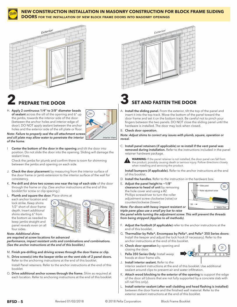
Install bumpers (if applicable). Refer to the anchor instructions at the end of this booklet.
D. Install the handles. Refer to the instruction in the hardware box.E. Adjust the panel height to ~1/8”
clearance to head of unit by removing the hole cover and using a #2 Phillips screwdriver to turn the roller adjustment screw clockwise (raise) or counterclockwise (lower).
Note: For doors with heavy impact resistant or triple pane glass use a small pry bar to raise the panel while turning the adjustment screw. This will prevent the threads from being stripped (Applies to all methods).
F. Adjust the footbolt (if applicable) refer to the anchor instructions at the end of this booklet.
G. ThermaStar by Pella®, Encompass by Pella®, and Pella® 350 Series doors: Install the keeper and adjust the lock hook (if necessary). Refer to the anchor instructions at the end of this booklet.
H. Check door operation by opening and closing the door.
I. Pella 350 Series Only: Install weep hoods at door frame sills.
J. Install interior sealant. Refer to the interior sealant instructions at the end of this booklet. Use additional sealant around clips to prevent air and water infiltration.
K. Attach wood blocking to the exterior of the opening to support the edge of the door sill (doors that are not fully supported by a concrete slab with sill nail fins only).
L. Install exterior sealant (after wall cladding and head flashing is installed) between the door frame and the finished wall material. Refer to the exterior sealant instructions at the end of this booklet.
H. Apply 2 continuous 1/4" to 3/8" diameter beads of sealant across the sill of the opening and 6" up the jambs, towards the interior side of the door (between the anchor holes and interior edge of door). DO NOT apply sealant between the anchor holes and the exterior side of the sill plate or floor.
Note: Failure to properly seal the sill attachment screws and sill plate may allow water to penetrate the interior of the home.
I Center the bottom of the door in the opening and tilt the door into position. Do not slide the door into the opening. Sliding will damage the sealant lines.
Check the jambs for plumb and confirm there is room for shimming between the jambs and opening on each side.
J. Check the door placement by measuring from the interior surface of the door frame or jamb extension to the interior surface of the wall for consistency.
K. Pre-drill and drive two screws one near the top of each side of the door through the frame or clip. (See anchor instructions at the end of this booklet for screw or clip spacing.)
L. Plumb and square the door. Place shims at each anchor location and lock strike. Keep shims 1/2" short of door frame depth. Insert additional shims starting 6" from the bottom as needed to keep jambs straight and panel reveals even on all four sides.
Note: Additional shims are required at screw locations for advanced performance, impact resistant units and combinations and combinations. (See the anchor instructions at the end of this booklet.)
M. Finish pre-drilling and driving screws through the door frame or clip.N. Drive screw(s) into the keeper strike on the vent side of 2 panel doors.
Refer to the anchoring instructions at the end of this booklet. Install Panel retainers. Refer to the anchor instructions at the end of this
booklet.O. Drive additional anchor screws through the frame. Shim as required at
each location. Refer to anchoring instructions at the end of this booklet.
NEW CONSTRUCTION INSTALLATION IN MASONRY CONSTRUCTION FOR BLOCK FRAME SLIDING DOORS for the installation of new block frame doors into masonry openings
3 SET AND FASTEN THE DOOR
A. Install the sliding panel. From the exterior, tilt the top of the panel and insert it into the top track. Move the bottom of the panel toward the door frame and set it on the bottom track. Be careful not to pinch your fingers between the two panels. DO NOT close the sliding panel until the hardware is installed. The door may lock when closed.
B. Check door operation.Note: Adjust shims to correct any issues with plumb, square, operation or reveal.
C. Install panel retainers (if applicable) or re-install if the vent panel was removed during installation. Refer to the instructions included in the panel retainer hardware package.
2L
12 0 3 0 4 0 5 0 6 0 7 0
23
INCHESmm
2L
Exterior
ExteriorExterior
Exterior
2
I
3I
2 PREPARE THE DOOR Interior View
18"
1-3/16"
3/8" drill
3/16" drill
slide
panel
Interior Viewanch
or
hole
6"2H
Sill
Roller adjustment screw
Interior View
Slide panel 3E
! WARNING: If the panel retainer is not installed, the door panel can fall from the product, possibly causing death or serious injury. Follow directions closely when installing and servicing the product.
© 2018 Pella Corporation Block Frame Booklet
BFSD – 6 Revised 01/02/2018
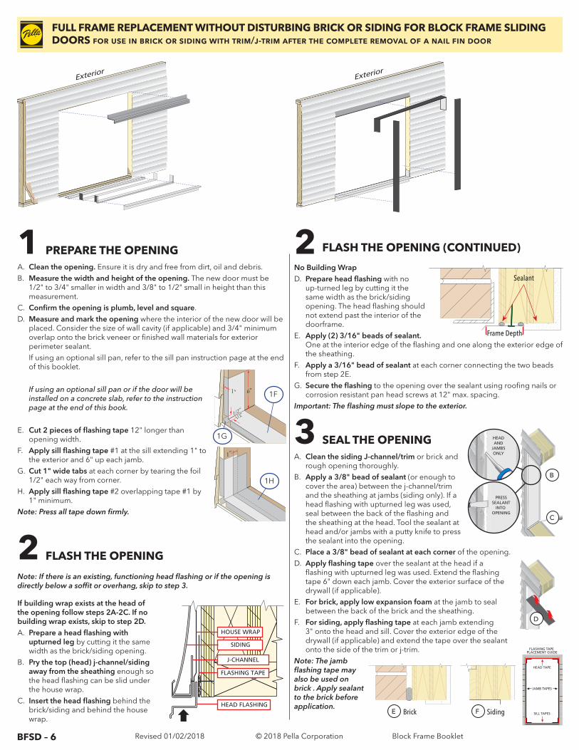
1 PREPARE THE OPENING
2 FLASH THE OPENING
Note: If there is an existing, functioning head flashing or if the opening is directly below a soffit or overhang, skip to step 3.
If building wrap exists at the head of the opening follow steps 2A-2C. If no building wrap exists, skip to step 2D.A. Prepare a head flashing with
upturned leg by cutting it the same width as the brick/siding opening.
B. Pry the top (head) j-channel/siding away from the sheathing enough so the head flashing can be slid under the house wrap.
C. Insert the head flashing behind the brick/siding and behind the house wrap.
2 FLASH THE OPENING (CONTINUED)
No Building WrapD. Prepare head flashing with no
up-turned leg by cutting it the same width as the brick/siding opening. The head flashing should not extend past the interior of the doorframe.
E. Apply (2) 3/16" beads of sealant. One at the interior edge of the flashing and one along the exterior edge of the sheathing.
F. Apply a 3/16" bead of sealant at each corner connecting the two beads from step 2E.
G. Secure the flashing to the opening over the sealant using roofing nails or corrosion resistant pan head screws at 12" max. spacing.
Important: The flashing must slope to the exterior.
3 SEAL THE OPENINGA. Clean the siding J-channel/trim or brick and
rough opening thoroughly.B. Apply a 3/8" bead of sealant (or enough to
cover the area) between the j-channel/trim and the sheathing at jambs (siding only). If a head flashing with upturned leg was used, seal between the back of the flashing and the sheathing at the head. Tool the sealant at head and/or jambs with a putty knife to press the sealant into the opening.
C. Place a 3/8" bead of sealant at each corner of the opening.D. Apply flashing tape over the sealant at the head if a
flashing with upturned leg was used. Extend the flashing tape 6" down each jamb. Cover the exterior surface of the drywall (if applicable).
E. For brick, apply low expansion foam at the jamb to seal between the back of the brick and the sheathing.
F. For siding, apply flashing tape at each jamb extending 3" onto the head and sill. Cover the exterior edge of the drywall (if applicable) and extend the tape over the sealant onto the side of the trim or j-trim.
Note: The jamb flashing tape may also be used on brick . Apply sealant to the brick before application.HEAD FLASHING
HOUSE WRAP
SIDING
FLASHING TAPE
J-CHANNEL
FULL FRAME REPLACEMENT WITHOUT DISTURBING BRICK OR SIDING FOR BLOCK FRAME SLIDING DOORS for use in brick or siding with trim/j-trim after the complete removal of a nail fin door
PRESSSEALANT
INTO OPENING
HEADAND
JAMBSONLY
B
C
1”
D
FLASHING TAPE PLACEMENT GUIDE
SILL TAPES
HEAD TAPE
JAMB TAPES
Brick SidingE F
A. Clean the opening. Ensure it is dry and free from dirt, oil and debris.B. Measure the width and height of the opening. The new door must be
1/2" to 3/4" smaller in width and 3/8" to 1/2" small in height than this measurement.
C. Confirm the opening is plumb, level and square.D. Measure and mark the opening where the interior of the new door will be
placed. Consider the size of wall cavity (if applicable) and 3/4" minimum overlap onto the brick veneer or finished wall materials for exterior perimeter sealant.
If using an optional sill pan, refer to the sill pan instruction page at the end of this booklet.
If using an optional sill pan or if the door will be installed on a concrete slab, refer to the instruction page at the end of this book.
E. Cut 2 pieces of flashing tape 12" longer than opening width.
F. Apply sill flashing tape #1 at the sill extending 1" to the exterior and 6" up each jamb.
G. Cut 1" wide tabs at each corner by tearing the foil 1/2" each way from corner.
H. Apply sill flashing tape #2 overlapping tape #1 by 1" minimum.
Note: Press all tape down firmly.
Interior
Exterior
Exterior
Exterior
Interior
Exterior
Exterior
Exterior
Frame Depth
Sealant
1"
1/2"1/2"
6"
1"
1F
1G
1"
1/2"1/2"
6"
1"
1H
© 2018 Pella Corporation Block Frame Booklet
BFSD – 7 Revised 01/02/2018
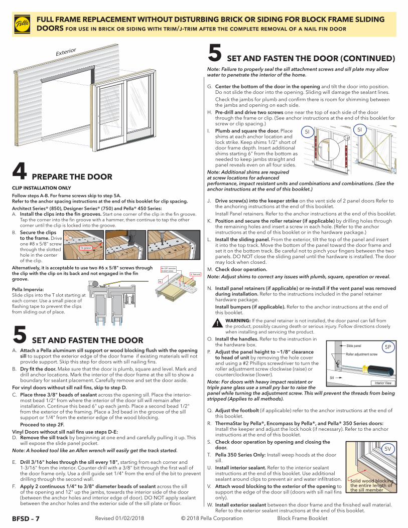
O. Install the handles. Refer to the instruction in the hardware box.
P. Adjust the panel height to ~1/8” clearance to head of unit by removing the hole cover and using a #2 Phillips screwdriver to turn the roller adjustment screw clockwise (raise) or counterclockwise (lower).
Note: For doors with heavy impact resistant or triple pane glass use a small pry bar to raise the panel while turning the adjustment screw. This will prevent the threads from being stripped (Applies to all methods).
Q. Adjust the footbolt (if applicable) refer to the anchor instructions at the end of this booklet.
R. ThermaStar by Pella®, Encompass by Pella®, and Pella® 350 Series doors: Install the keeper and adjust the lock hook (if necessary). Refer to the anchor instructions at the end of this booklet.
S. Check door operation by opening and closing the door.
T. Pella 350 Series Only: Install weep hoods at the door sill.
U. Install interior sealant. Refer to the interior sealant instructions at the end of this booklet. Use additional sealant around clips to prevent air and water infiltration.
V. Attach wood blocking to the exterior of the opening to support the edge of the door sill (doors with sill nail fins only).
W. Install exterior sealant between the door frame and the finished wall material. Refer to the exterior sealant instructions at the end of this booklet.
Note: Failure to properly seal the sill attachment screws and sill plate may allow water to penetrate the interior of the home.
G. Center the bottom of the door in the opening and tilt the door into position. Do not slide the door into the opening. Sliding will damage the sealant lines.
Check the jambs for plumb and confirm there is room for shimming between the jambs and opening on each side.
H. Pre-drill and drive two screws one near the top of each side of the door through the frame or clip. (See anchor instructions at the end of this booklet for screw or clip spacing.)
I. Plumb and square the door. Place shims at each anchor location and lock strike. Keep shims 1/2" short of door frame depth. Insert additional shims starting 6" from the bottom as needed to keep jambs straight and panel reveals even on all four sides.
Note: Additional shims are required at screw locations for advanced performance, impact resistant units and combinations and combinations. (See the anchor instructions at the end of this booklet.)
J. Drive screw(s) into the keeper strike on the vent side of 2 panel doors Refer to the anchoring instructions at the end of this booklet.
Install Panel retainers. Refer to the anchor instructions at the end of this booklet.K. Position and secure the roller retainer (if applicable) by drilling holes through
the remaining holes and insert a screw in each hole. (Refer to the anchor instructions at the end of this booklet or in the hardware package.)
L. Install the sliding panel. From the exterior, tilt the top of the panel and insert it into the top track. Move the bottom of the panel toward the door frame and set it on the bottom track. Be careful not to pinch your fingers between the two panels. DO NOT close the sliding panel until the hardware is installed. The door may lock when closed.
M. Check door operation.Note: Adjust shims to correct any issues with plumb, square, operation or reveal.
N. Install panel retainers (if applicable) or re-install if the vent panel was removed during installation. Refer to the instructions included in the panel retainer hardware package.
Install bumpers (if applicable). Refer to the anchor instructions at the end of this booklet.
Architect Series® (850), Designer Series® (750) and Pella® 450 Series:A. Install the clips into the fin grooves. Start one corner of the clip in the fin groove.
Tap the corner into the fin groove with a hammer, then continue to tap the other corner until the clip is locked into the groove.
B. Secure the clips to the frame. Drive one #8 x 5/8" screw through the slotted hole in the center of the clip.
Alternatively, it is acceptable to use two #6 x 5/8" screws through the clip with the clip on its back and not engaged in the fin groove.
FULL FRAME REPLACEMENT WITHOUT DISTURBING BRICK OR SIDING FOR BLOCK FRAME SLIDING DOORS for use in brick or siding with trim/j-trim after the complete removal of a nail fin door
4 PREPARE THE DOOR
6“ from end
Lip
#6 x 5/8” corrosionresistant screws
Fin groove
CLIP INSTALLATION ONLY
Follow steps A-B. For frame screws skip to step 5A.Refer to the anchor spacing instructions at the end of this booklet for clip spacing.
5 SET AND FASTEN THE DOOR (CONTINUED)
Exterior
5IExterior
5I
5 SET AND FASTEN THE DOOR
Interior
Exterior
Exterior
Exterior
Pella Impervia:Slide clips into the T slot starting at each corner. Use a small piece of flashing tape to prevent the clips from sliding out of place.
A. Attach a Pella aluminum sill support or wood blocking flush with the opening sill to support the exterior edge of the door frame if existing materials will not provide support. Skip this step for doors with sill nailing fins.
B. Dry fit the door. Make sure that the door is plumb, square and level. Mark and drill anchor locations. Mark the interior of the door frame at the sill to show a boundary for sealant placement. Carefully remove and set the door aside.
For vinyl doors without sill nail fins, skip to step D.C. Place three 3/8" beads of sealant across the opening sill. Place the interior-
most bead 1/2" from where the interior of the door sill will remain after installation. Continue this bead 6" up each jamb. Place a second bead 1/2" from the exterior of the framing. Place a 3rd bead in the groove of the sill support or 1/4" from the exterior edge of the wood blocking.
Proceed to step 2F.Vinyl Doors without sill nail fins use steps D-E:D. Remove the sill track by beginning at one end and carefully pulling it up. This
will expose the slide panel pocket.Note: A hooked tool like an Allen wrench will easily get the track started.
E. Drill 3/16" holes through the sill every 18", starting from each corner and 1-3/16" from the interior. Counter-drill with a 3/8" bit through the first wall of the door frame only. Use a drill guide set 1/4" from the end of the bit to prevent drilling through the second wall.
F. Apply 2 continuous 1/4" to 3/8" diameter beads of sealant across the sill of the opening and 12" up the jambs, towards the interior side of the door (between the anchor holes and interior edge of door). DO NOT apply sealant between the anchor holes and the exterior side of the sill plate or floor.
Solid wood blocking the entire length of the sill member
5V
! WARNING: If the panel retainer is not installed, the door panel can fall from the product, possibly causing death or serious injury. Follow directions closely when installing and servicing the product.
Sill
Roller adjustment screw
Interior View
Slide panel 5P
© 2018 Pella Corporation Block Frame Booklet
BFSD – 8 Revised 01/02/2018
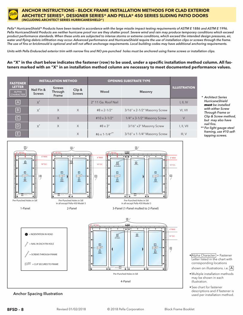
ANCHOR INSTRUCTIONS - BLOCK FRAME INSTALLATION METHODS FOR CLAD EXTERIOR ARCHITECT SERIES®, DESIGNER SERIES® AND PELLA® 450 SERIES SLIDING PATIO DOORS(INCLUDING ARCHITECT SERIES HURRICANESHIELD®)
Pella® HurricaneShield® Products have been tested in accordance with the large missile impact testing requirements of ASTM E 1886 and ASTM E 1996. Pella HurricaneShield Products are neither hurricane proof nor are they shatter proof. Severe wind and rain may produce temporary conditions which exceed product performance standards. When these units are subjected to intense storms or extreme conditions, which exceed the intended design pressures, air, water and flying debris infiltration may occur. Advanced performance and HurricaneShield require the use of installation clips or screws through the frame. The use of fins or brickmould is optional and will not affect anchorage requirements. Local building codes may have additional anchoring requirements.
Units with Pella Enduraclad exterior trim with narrow fins and NO pre-punched holes must be anchored using frame screws or installation clips.
FASTENER LETTER
ALPHA CHARACTER
INSTALLATION METHOD OPENING SUBSTRATE TYPE
ILLUSTRATIONNail Fin &
Screws
Screws Through Frame
Clip & Screws Wood Masonry
A X* 2” 11 Ga. Roof Nail I, II, IV
B X* X X #8 x 2-1/2” 3/16” x 2-1/2” Masonry Screw VI, VII
C X #10 x 3-1/2” 1/4” x 3-1/2” Masonry Screw V
D X* X X #8 x 3” 3/16” x3” Masonry Screw I, II, VII
E X #6 x 1-1/4”** 3/16” x 1-1/4” Masonry Screw III, V
Anchor Spacing Illustration
An "X" in the chart below indicates the fastener (row) to be used, under a specific installation method column. All fas-teners marked with an "X" in an installation method column are necessary to meet documented performance values.
• Alpha Character = Fastener Letter listed in the chart with corresponding locations
shown on illustrations. i.e. A
• Multiple installation methods may be shown in each illustration.
• See chart for fastener descriptions and if fastener is used per installation method.
* Architect Series HurricaneShield must be installed with either Screw Through Frame or Clip & Screw method, but may also have nail fins.
** For light gauge steel framing, use #10 self-tapping screws.
or
= INDENTATION IN HEAD
= NAIL IN EACH FIN HOLE
= SCREWS THROUGH FRAME
= CLIP SECURED TO FRAME
1-Panel 2-Panel 3-Panel (1-Panel mulled to 2-Panel)
Pre-Punched Holes in Sill in all except Pella 450 Model 3
Pre-Punched Holes in Sill in all except Pella 450 Model 3
Pre-Punched Holes in Sill
6” 10” O.C.
A
6” MAX
16” O.C.
6” MAX
16” O.C.
or or
6” MAX
16” O.C.
6” 10” O.C.
At Mullion
ororC
6” 10” O.C.
4-Panel
Pre-Punched Holes in Sill
At Seam
D
or or
6” 10” O.C.
6” MAX
16” O.C.
A A
A
A
CCC C
BBB
D D D D
D
C C
B
E E
AAA
E E E E E
© 2018 Pella Corporation Block Frame Booklet

BFSD – 9 Revised 01/02/2018
ANCHOR INSTRUCTIONS - BLOCK FRAME INSTALLATION METHODS FOR CLAD EXTERIOR ARCHITECT SERIES®, DESIGNER SERIES® AND PELLA® 450 SERIES SLIDING PATIO DOORS(INCLUDING ARCHITECT SERIES HURRICANESHIELD®)
Lip
#6 x 5/8” corrosionresistant screws
6“ from end
Lip
#6 x 5/8” corrosionresistant screws
Shim
E
3/16”
A
D
A A
(At Mullion or At Seam) See Illustration I
Fixed Head Stop
Screen Track
or
3/16”
A
DD
(Remove track/stop, install screws, reinstall.)
Head, 1-Panel, 2-Panel
Illustration I
Head, 3-Panel, 4-Panel
Illustration II
Illustration III
Nail Fin, Jambs
Illustration IV
(Optional / Alternate) (Optional / Alternate)
C
CC
C
E E
Clips may be bent 90˚ outward
Add sealant to exterior holes before installing screws.
Clips may be bent 90˚ outwardClip/Screw, Jambs
Illustration V
shim
B
Jamb with lock strikes (1 or 2 strikes may be present)
Note: Strikes Factory installed for 4-Panel and 3-Panel with mulled lock jambs.
Illustration VII
Install cover after screws
D
OR
Clip and Screw Installation Method Jamb Clips
Sill
Illustration VI
B
Interior
Exterior
Fixed Panel Threshold
Drive screws through plugs at each pre-punched hole or drill pilot holes if none are present. Add sealant in drilled pilot holes before installing screws.
11" (centered on edge of �xed panel)
5.5" 8.5" 8.5"
from jamb or seam
Exterior sill edge must be supported to meet performance values. Apply Pella aluminum sill
support or wood blocking as required to support the exterior edge of the door frame.
Reapply the vent panel retainer after all anchoring is complete and vent panel is installed.
© 2018 Pella Corporation Block Frame Booklet
BFSD – 10 Revised 01/02/2018
ProductAnchor Type
Instructions IllustrationWood Masonry
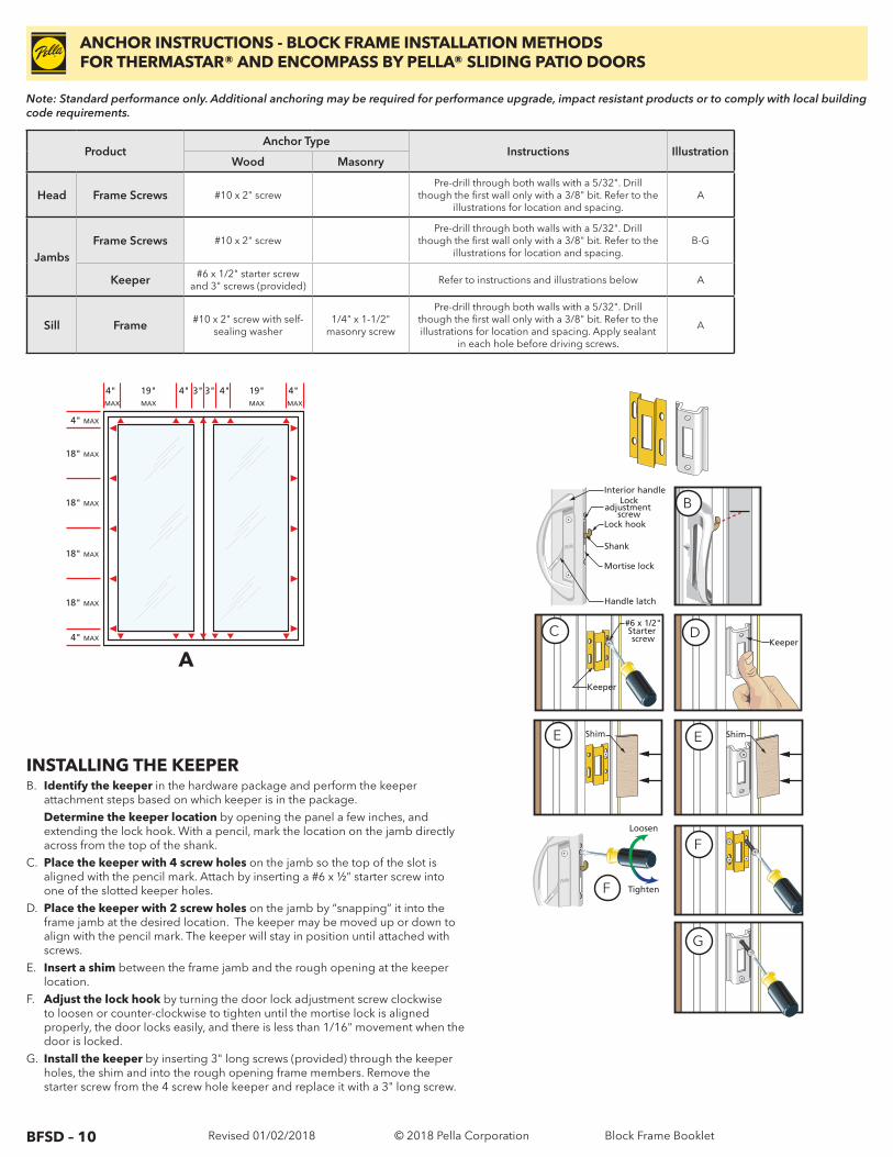
Head Frame Screws #10 x 2" screwPre-drill through both walls with a 5/32". Drill
though the first wall only with a 3/8" bit. Refer to the illustrations for location and spacing.
A
JambsFrame Screws #10 x 2" screw
Pre-drill through both walls with a 5/32". Drill though the first wall only with a 3/8" bit. Refer to the
illustrations for location and spacing.B-G
Keeper #6 x 1/2" starter screw and 3" screws (provided)
Refer to instructions and illustrations below A
Sill Frame #10 x 2" screw with self-sealing washer
1/4" x 1-1/2" masonry screw
Pre-drill through both walls with a 5/32". Drill though the first wall only with a 3/8" bit. Refer to the illustrations for location and spacing. Apply sealant
in each hole before driving screws.
A
ANCHOR INSTRUCTIONS - BLOCK FRAME INSTALLATION METHODS FOR THERMASTAR® AND ENCOMPASS BY PELLA® SLIDING PATIO DOORS
Note: Standard performance only. Additional anchoring may be required for performance upgrade, impact resistant products or to comply with local building code requirements.
A
INSTALLING THE KEEPERB. Identify the keeper in the hardware package and perform the keeper
attachment steps based on which keeper is in the package. Determine the keeper location by opening the panel a few inches, and
extending the lock hook. With a pencil, mark the location on the jamb directly across from the top of the shank.
C. Place the keeper with 4 screw holes on the jamb so the top of the slot is aligned with the pencil mark. Attach by inserting a #6 x ½” starter screw into one of the slotted keeper holes.
D. Place the keeper with 2 screw holes on the jamb by “snapping” it into the frame jamb at the desired location. The keeper may be moved up or down to align with the pencil mark. The keeper will stay in position until attached with screws.
E. Insert a shim between the frame jamb and the rough opening at the keeper location.
F. Adjust the lock hook by turning the door lock adjustment screw clockwise to loosen or counter-clockwise to tighten until the mortise lock is aligned properly, the door locks easily, and there is less than 1/16" movement when the door is locked.
G. Install the keeper by inserting 3" long screws (provided) through the keeper holes, the shim and into the rough opening frame members. Remove the starter screw from the 4 screw hole keeper and replace it with a 3" long screw.
Keeper
#6 x 1/2" Starter screw
Tighten
Loosen
5D 5E
5FShim5F
5H
5H
5G
Lock hook
Interior handle
Shank
Handle latch
Lockadjustment
screw
Mortise lock
Shim
Keeper
5CB
C D
E E
F
F
G
4" MAX
19"MAX
4" 4"3" 3" 19"MAX
4" MAX
4" MAX
18" MAX
18" MAX
18" MAX
18" MAX
4" MAX
© 2018 Pella Corporation Block Frame Booklet
BFSD – 11 Revised 01/02/2018
ProductAnchor Type
Instructions IllustrationWood Masonry
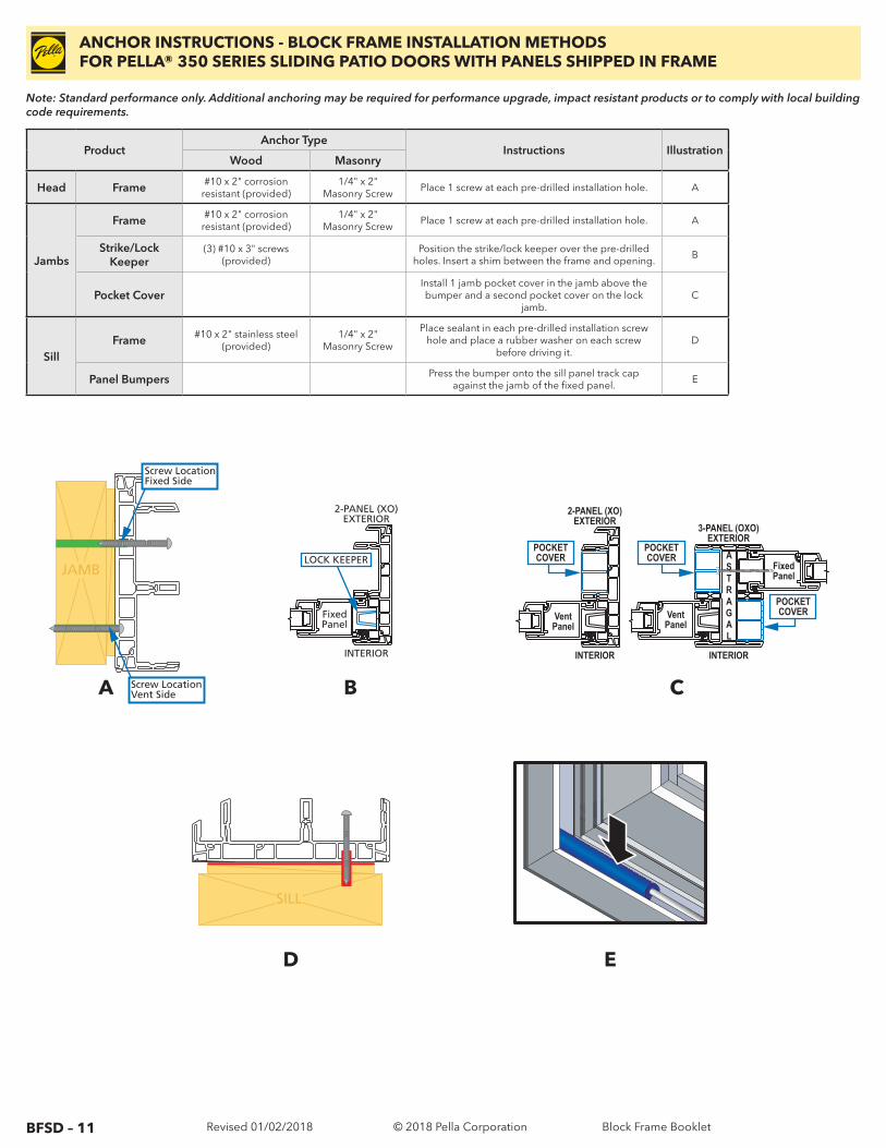
Head Frame #10 x 2" corrosion resistant (provided)
1/4" x 2" Masonry Screw
Place 1 screw at each pre-drilled installation hole. A
Jambs
Frame #10 x 2" corrosion resistant (provided)
1/4" x 2" Masonry Screw
Place 1 screw at each pre-drilled installation hole. A
Strike/Lock Keeper
(3) #10 x 3" screws (provided)
Position the strike/lock keeper over the pre-drilled holes. Insert a shim between the frame and opening.
B
Pocket CoverInstall 1 jamb pocket cover in the jamb above the bumper and a second pocket cover on the lock
jamb.C
SillFrame #10 x 2" stainless steel
(provided)1/4" x 2"
Masonry Screw
Place sealant in each pre-drilled installation screw hole and place a rubber washer on each screw
before driving it.D
Panel Bumpers Press the bumper onto the sill panel track cap against the jamb of the fixed panel.
E
ANCHOR INSTRUCTIONS - BLOCK FRAME INSTALLATION METHODS FOR PELLA® 350 SERIES SLIDING PATIO DOORS WITH PANELS SHIPPED IN FRAME
Note: Standard performance only. Additional anchoring may be required for performance upgrade, impact resistant products or to comply with local building code requirements.
JAMB
Screw Location Fixed Side
Screw Location Vent SideA B C
D E
SILL
INTERIOR
2-PANEL (XO) EXTERIOR
Fixed Panel
Vent Panel
Vent Panel
A S T R A G A L
INTERIOR
4-PANEL (OXXO) EXTERIOR
LOCK KEEPER
3-PANEL (OXO) EXTERIOR
Fixed Panel
A S T R A G A L
INTERIOR
Vent Panel
LOCK KEEPER LOCK KEEPER POCKETCOVER
INTERIOR
2-PANEL (XO)EXTERIOR
VentPanel
POCKETCOVER
POCKETCOVER
3-PANEL (OXO)EXTERIOR
FixedPanel
ASTRAGAL
INTERIOR
VentPanel
POCKETCOVER
POCKETCOVER
VentPanel
VentPanel
ASTRAGAL
INTERIOR
4-PANEL (OXXO)EXTERIOR
© 2018 Pella Corporation Block Frame Booklet
BFSD – 12 Revised 01/02/2018
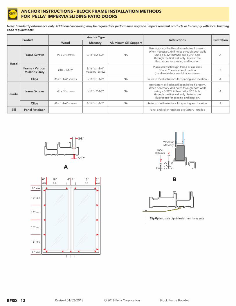
ProductAnchor Type
Instructions IllustrationWood Masonry Aluminum Sill Support
Head
Frame Screws #8 x 3" screws 3/16" x 2-1/2" NA
Use factory-drilled installation holes if present. When necessary, drill holes through both walls
using a 5/32" bit then drill a 3/8" hole through the first wall only. Refer to the illustrations for spacing and location.
A
Frame - Vertical Mullions Only
#10 x 1-1/2"3/16" x 1-3/4"
Masonry Screw
Place screws through frame or use clips 3" and 6" each side of mullion
(multi-wide door combinations only).B
Clips #8 x 1-1/4" screws 3/16" x 1-1/2" NA Refer to the illustrations for spacing and location. A
JambsFrame Screws #8 x 3" screws 3/16" x 2-1/2" NA
Use factory-drilled installation holes if present. When necessary, drill holes through both walls
using a 5/32" bit then drill a 3/8" hole through the first wall only. Refer to the illustrations for spacing and location.
A
Clips #8 x 1-1/4" screws 3/16" x 1-1/2" NA Refer to the illustrations for spacing and location. A
Sill Panel Retainer Panel and roller retainers are factory-installed
ANCHOR INSTRUCTIONS - BLOCK FRAME INSTALLATION METHODS FOR PELLA® IMPERVIA SLIDING PATIO DOORS
Note: Standard performance only. Additional anchoring may be required for performance upgrade, impact resistant products or to comply with local building code requirements.
Wood or Masonry
Panel Retainer
B6" MAX
16"O.C.
4"4" 16"O.C.
6" MAX
6" MAX
16" O.C.
16" O.C.
16" O.C.
16" O.C.
6" MAX
3/8"
5/32"
A
Clip Option: slide clips into slot from frame ends
© 2018 Pella Corporation Block Frame Booklet
BFSD – 13 Revised 01/02/2018
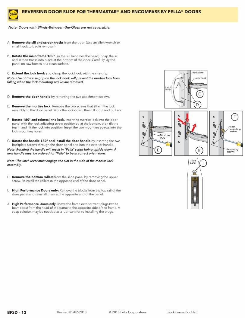
REVERSING DOOR SLIDE FOR THERMASTAR® AND ENCOMPASS BY PELLA® DOORS
Note: Doors with Blinds-Between-the-Glass are not reversible.
A. Remove the sill and screen tracks from the door. (Use an allen wrench or small hook to begin removal.)
B. Rotate the main frame 180° (so the sill becomes the head). Snap the sill and screen tracks into place at the bottom of the door. Carefully lay the panel on saw horses or a clean surface.
C. Extend the lock hook and clamp the lock hook with the vise grip. Note: Use of the vise grip on the lock hook will prevent the mortise lock from falling when the lock mounting screws are removed.
D. Remove the door handle by removing the two attachment screws.
E. Remove the mortise lock. Remove the two screws that attach the lock assembly to the door panel. Work the lock down, then tilt it out and pull up.
F. Rotate 180° and reinstall the lock. Insert the mortise lock into the door panel with the lock adjusting screw positioned at the bottom, then tilt the top in and lift the lock into position. Insert the two mounting screws into the lock mounting holes.
G. Rotate the handle 180° and install the door handle by inserting the two backplate screws through the door panel and into the exterior handle.
Note: Rotating the handle will result in "Pella" script being upside down. A new handle must be ordered for "Pella" to be in correct orientation.
Note: The latch lever must engage the slot in the side of the mortise lock assembly.
H. Remove the bottom rollers from the slide panel by removing the upper screw. Reinstall the rollers in the opposite end of the door panel.
I. High Performance Doors only: Remove the blocks from the top rail of the door panel and reinstall them at the opposite end of the panel.
J. High Performance Doors only: Move the frame exterior vent plugs (white foam rods) from the head of the frame to the opposite side of the frame. A soap solution may be needed as a lubricant for re-installing the plugs.
Lock hook
C
Latchlever
Backplate
D
Mortiselock
E
3
12
E
Lockadjustingscrew
Mountingscrews
F
Slidepanel I
C
D
E E
F
I
© 2018 Pella Corporation Block Frame Booklet
BFSD – 14 Revised 01/02/2018
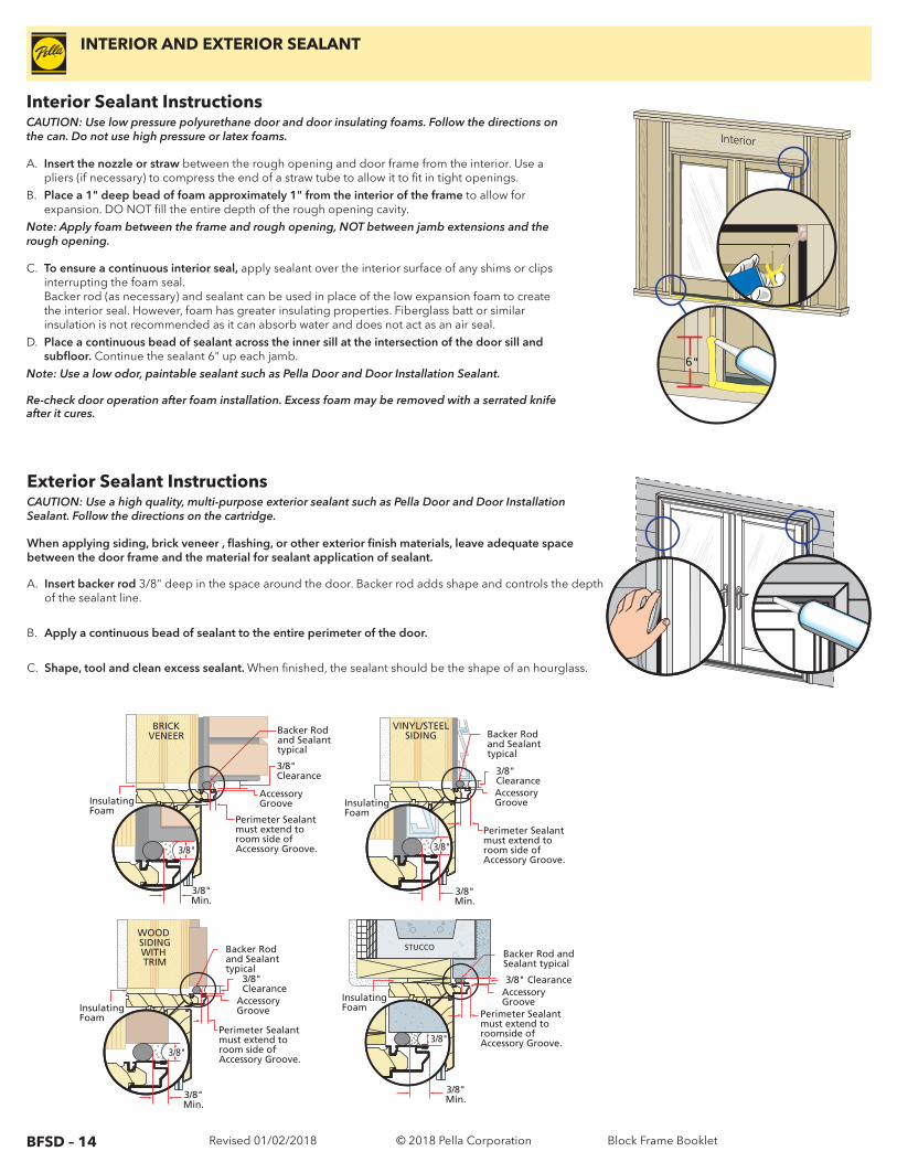
Interior Sealant InstructionsCAUTION: Use low pressure polyurethane door and door insulating foams. Follow the directions on the can. Do not use high pressure or latex foams.
A. Insert the nozzle or straw between the rough opening and door frame from the interior. Use a pliers (if necessary) to compress the end of a straw tube to allow it to fit in tight openings.
B. Place a 1" deep bead of foam approximately 1" from the interior of the frame to allow for expansion. DO NOT fill the entire depth of the rough opening cavity.
Note: Apply foam between the frame and rough opening, NOT between jamb extensions and the rough opening.
C. To ensure a continuous interior seal, apply sealant over the interior surface of any shims or clips interrupting the foam seal. Backer rod (as necessary) and sealant can be used in place of the low expansion foam to create the interior seal. However, foam has greater insulating properties. Fiberglass batt or similar insulation is not recommended as it can absorb water and does not act as an air seal.
D. Place a continuous bead of sealant across the inner sill at the intersection of the door sill and subfloor. Continue the sealant 6" up each jamb.
Note: Use a low odor, paintable sealant such as Pella Door and Door Installation Sealant.
Re-check door operation after foam installation. Excess foam may be removed with a serrated knife after it cures.
Exterior Sealant InstructionsCAUTION: Use a high quality, multi-purpose exterior sealant such as Pella Door and Door Installation Sealant. Follow the directions on the cartridge.
When applying siding, brick veneer , flashing, or other exterior finish materials, leave adequate space between the door frame and the material for sealant application of sealant.
A. Insert backer rod 3/8" deep in the space around the door. Backer rod adds shape and controls the depth of the sealant line.
B. Apply a continuous bead of sealant to the entire perimeter of the door.
C. Shape, tool and clean excess sealant. When finished, the sealant should be the shape of an hourglass.
Interior
6"
BRICKVENEER
3/8" Clearance
Backer Rod and Sealant typical
Insulating Foam
Perimeter Sealant must extend to room side of Accessory Groove.
Accessory Groove
3/8"Min.
3/8"
3/8"Min.
3/8"
VINYL/STEELSIDING
3/8" Clearance
Backer Rod and Sealant typical
InsulatingFoam
Perimeter Sealant must extend to room side of Accessory Groove.
Accessory Groove
STUCCO
3/8" Clearance
Backer Rod andSealant typical
Perimeter Sealant must extend to roomside of Accessory Groove.
Accessory GrooveInsulating
Foam
3/8"Min.
3/8"
InsulatingFoam
Perimeter Sealant must extend to room side of Accessory Groove.
WOOD SIDINGWITH TRIM
3/8" Clearance
Accessory Groove
Backer Rod and Sealant typical
3/8"Min.
3/8"
INTERIOR AND EXTERIOR SEALANT
© 2018 Pella Corporation Block Frame Booklet
BFSD – 15 Revised 01/02/2018
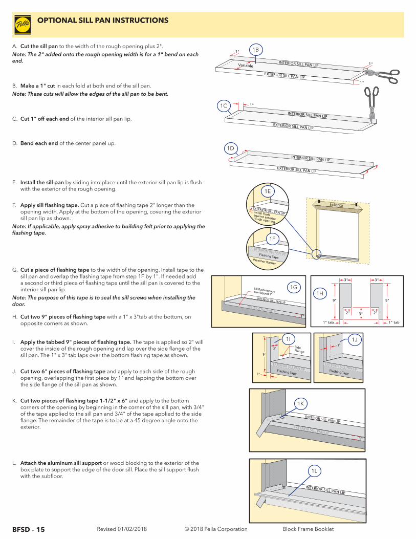
OPTIONAL SILL PAN INSTRUCTIONS
A. Cut the sill pan to the width of the rough opening plus 2".Note: The 2" added onto the rough opening width is for a 1" bend on each end.
B. Make a 1" cut in each fold at both end of the sill pan.Note: These cuts will allow the edges of the sill pan to be bent.
C. Cut 1" off each end of the interior sill pan lip.
D. Bend each end of the center panel up.
INTERIOR SILL PAN LIP
EXTERIOR SILL PAN LIP 1"
1"
Variable1"
INTERIOR SILL PAN LIP
EXTERIOR SILL PAN LIP
1"
INTERIOR SILL PAN LIP
EXTERIOR SILL PAN LIP
Exterior EXTERIOR SILL PAN LIP Install flush against exterior rough opening.
EXTERIOR SILL PAN LIP Flashing Tape Weather Barrier
9"
3"
1" tab
3"
2"
9"
1" tab
3"
2"
EXTERIOR SILL PAN LIPFlashing Tape
9"
1"
2" SideFlange
EXTERIOR SILL PAN LIPFlashing Tape
1"
1B
1C
1D
1E
1F
1H
1I 1J
EXTERIOR SILL PAN LIP
INTERIOR SILL PAN LIP
1"
EXTERIOR SILL PAN LIP
INTERIOR SILL PAN LIP
1K
1L
EXTERIOR SILL PAN LIP
INTERIOR SILL PAN LIP
1"
Sill �ashing tape overlapped 1"
1G
E. Install the sill pan by sliding into place until the exterior sill pan lip is flush with the exterior of the rough opening.
F. Apply sill flashing tape. Cut a piece of flashing tape 2" longer than the opening width. Apply at the bottom of the opening, covering the exterior sill pan lip as shown.
Note: If applicable, apply spray adhesive to building felt prior to applying the flashing tape.
G. Cut a piece of flashing tape to the width of the opening. Install tape to the sill pan and overlap the flashing tape from step 1F by 1". If needed add a second or third piece of flashing tape until the sill pan is covered to the interior sill pan lip.
Note: The purpose of this tape is to seal the sill screws when installing the door.
H. Cut two 9" pieces of flashing tape with a 1" x 3"tab at the bottom, on opposite corners as shown.
I. Apply the tabbed 9" pieces of flashing tape. The tape is applied so 2" will cover the inside of the rough opening and lap over the side flange of the sill pan. The 1" x 3" tab laps over the bottom flashing tape as shown.
J. Cut two 6" pieces of flashing tape and apply to each side of the rough
opening, overlapping the first piece by 1" and lapping the bottom over the side flange of the sill pan as shown.
K. Cut two pieces of flashing tape 1-1/2" x 6" and apply to the bottom corners of the opening by beginning in the corner of the sill pan, with 3/4" of the tape applied to the sill pan and 3/4" of the tape applied to the side flange. The remainder of the tape is to be at a 45 degree angle onto the exterior.
L. Attach the aluminum sill support or wood blocking to the exterior of the box plate to support the edge of the door sill. Place the sill support flush with the subfloor.
© 2018 Pella Corporation Block Frame Booklet
BFSD – 16 Revised 01/02/2018
Cleaning InstructionsGLASSRemove any protective film and labels and clean the glass, using a soft, clean, grit-free cloth and mild soap or detergent. Be sure to remove all liquid by wiping dry or use a clean squeegee.
PELLA® ALUMINUM CLAD OR IMPERVIA FRAMESThe interior and exterior frame and sash are protected with a tough factory finish. Clean this surface with mild soap and water. Stubborn stains and deposits may be removed with mineral spirits. DO NOT use abrasives. DO NOT scrape or use tools that might damage the surface.
Notice: DO NOT use inappropriate solvents or brickwash or cleaning chemicals. If you do, permanent damage can result and the product failure, loss or damage would not be covered by the Limited Warranty.
ENCOMPASS BY PELLA®/THERMASTAR BY PELLA® AND PELLA® 350 SERIES WINDOWS FRAMES: The vinyl frame may be cleaned using the same method as the glass. For stubborn dirt, a “nonabrasive" cleaner such as Bon-Ami® or Soft Scrub® may be used. Do not use solvents such as mineral spirits, toluene, xylene, naphtha or muriatic acid as they can dull the finish, soften the vinyl and/or cause failure of the insulated unit seal. Keep door tracks clear of dirt and debris. Keep weep holes open and clear of obstructions.
Interior Finish (Wood Sliding Doors)If products cannot be finished immediately, cover with clear plastic to protect from dirt, damage and moisture. Remove any construction residue before finishing. Sand all wood surfaces lightly with 180 grit or finer sandpaper. DO NOT use steel wool. BE CAREFUL NOT TO SCRATCH THE GLASS. Remove sanding dust. Pella products must be finished according to these instructions; failure to follow these instructions voids the Limited Warranty. Finishing panel edges is optional for Patio Doors.
Note: To maintain proper product performance do not paint, finish or remove the weather stripping, mohair dust pads, gaskets or vinyl parts. Air and water leakage will result if these parts are removed. After finishing, allow venting windows and doors to dry completely before closing them.
Pella Corporation is not responsible for interior paint and stain finish imperfections for any product that is not factory-applied by Pella Corporation. For additional information on finishing see the Pella Owner’s Manual or go to www.pella.com.
Care and MaintenanceCare and maintenance information is available by contacting your local Pella retailer. This information is also available at www.pella.com.
IMPORTANT NOTICEBecause all construction must anticipate some water infiltration, it is important that the wall system be designed and constructed to properly manage moisture. Pella Corporation is not responsible for claims or damages caused by anticipated and unanticipated water infiltration; deficiencies in building design, construction and maintenance; failure to install Pella products in accordance with Pella’s installation instructions; or the use of Pella products in wall systems which do not allow for proper management of moisture within the wall systems. The determination of the suitability of all building components, including the use of Pella products, as well as the design and installation of flashing and sealing systems are the responsibility of the Buyer or User, the architect, contractor, installer, or other construction professional and are not the responsibility of Pella.Pella products should not be used in barrier wall systems which do not allow for proper management of moisture within the wall systems, such as barrier Exterior Insulation and Finish Systems (EIFS) (also known as synthetic stucco) or other non-water managed systems. Except in the states of California, New Mexico, Arizona, Nevada, Utah and Colorado, Pella makes no warranty of any kind on and assumes no responsibility for Pella windows and doors installed in barrier wall systems. In the states listed above, the installation of Pella Products in barrier wall or similar systems must be in accordance with Pella’s installation instructions. Product modifications that are not approved by Pella Corporation will void the warranty.
CLEANING INSTRUCTIONS
© 2018 Pella Corporation Block Frame Booklet