Embed Size (px)
Citation preview

Pelican Lake SAGD PilotAER Approval 11469C
AER D054 Annual Update January 1, 2015 – December 31, 2015
April 13, 2016

2
Disclaimer
This Cenovus Pelican Lake SAGD Pilot January 1, 2015 to December 31, 2015 Update (“Update”) is prepared and submitted pursuant to regulatory requirements promulgated by the Alberta Energy Regulator (“AER”) under its Directive 054 dated March 17, 2016. The contents of this Update are not intended to be, and may not be relied upon by any person, company, trust, partnership or other entity (“Person”) for the purpose of making any investment decision, including without limitation any decision to purchase, hold or sell any securities of Cenovus Energy Inc. or any of its affiliates (“Cenovus”).
Cenovus expressly disclaims, and makes no representation or warranty, express or implied, with respect to any of the information made available in this Update where such information is used by any Person for the purposes of making any investment decision as prohibited by this disclaimer, and none of Cenovus and its affiliates, and their respective officers, directors, employees, agents, advisors and contractors shall have any liability to any Person in respect thereof.
April 2016

Agenda
• Project Overview• Geological Overview• Resource Recovery• Facility Update• Compliance
3April 2016

1) Scheme Overview
Subsection 3.1.1
5
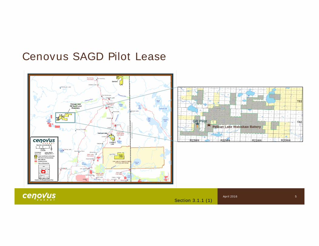
Cenovus SAGD Pilot Lease
T82
T83
R21W4R23W4 R22W4 R20W4
GR PilotPelican Lake Wabiskaw Battery
Section 3.1.1 (1)April 2016
6
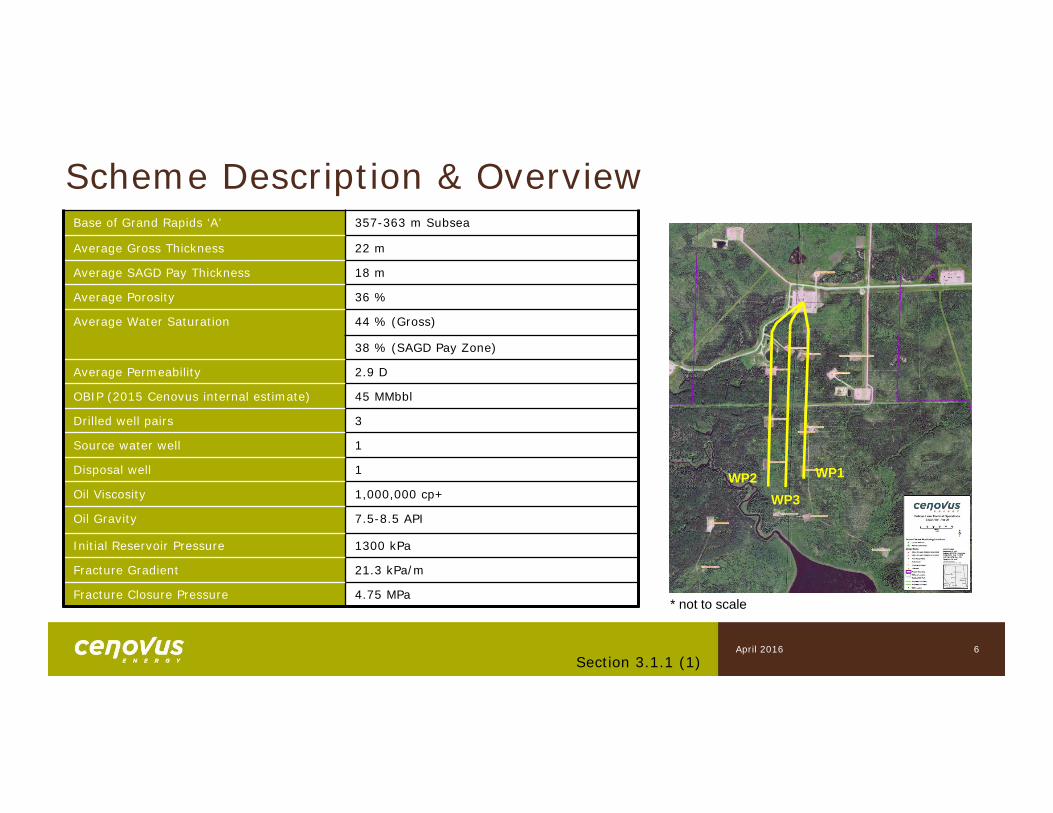
Scheme Description & OverviewBase of Grand Rapids ‘A’ 357-363 m Subsea
Average Gross Thickness 22 m
Average SAGD Pay Thickness 18 m
Average Porosity 36 %
Average Water Saturation 44 % (Gross)
38 % (SAGD Pay Zone)
Average Permeability 2.9 D
OBIP (2015 Cenovus internal estimate) 45 MMbbl
Drilled well pairs 3
Source water well 1
Disposal well 1
Oil Viscosity 1,000,000 cp+
Oil Gravity 7.5-8.5 API
Initial Reservoir Pressure 1300 kPa
Fracture Gradient 21.3 kPa/m
Fracture Closure Pressure 4.75 MPa
WP1WP2WP3
* not to scale
Section 3.1.1 (1)April 2016

2) Geology/Geoscience
Subsection 3.1.1
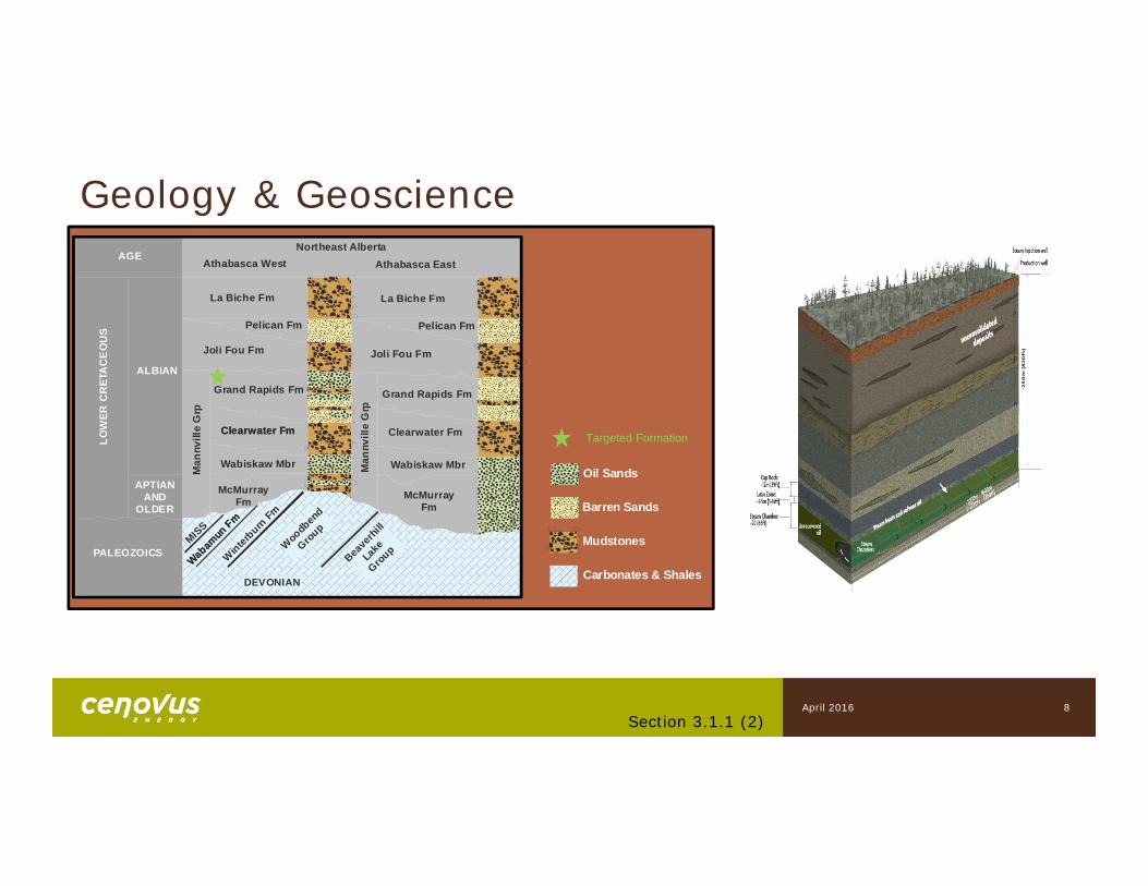
Oil Sands
Barren Sands
Carbonates & Shales
Mudstones
ALBIAN
LOW
ER C
RET
AC
EO
US
AGE
APTIAN AND
OLDER
Northeast AlbertaAthabasca West Athabasca East
La Biche FmLa Biche Fm
Pelican Fm Pelican Fm
Joli Fou Fm Joli Fou Fm
Grand Rapids Fm Grand Rapids Fm
Clearwater Fm Clearwater Fm
PALEOZOICS
Wabiskaw Mbr
McMurray Fm McMurray
Fm
Man
nvill
e G
rp
Man
nvill
e G
rp
Clearwater Fm
DEVONIAN
MISS
Winterb
urn Fm
Beaverh
illLake
GroupW
oodbend
Group
Wabamun Fm
Wabamun Fm
Wabiskaw Mbr
Targeted Formation
8
Geology & Geoscience
Section 3.1.1 (2)April 2016
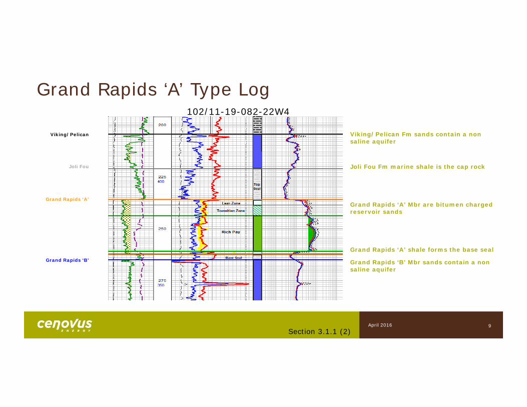
Grand Rapids ‘A’ Type Log
Viking/Pelican Fm sands contain a non saline aquifer
Joli Fou Fm marine shale is the cap rock
Grand Rapids ‘A’ Mbr are bitumen charged reservoir sands
Grand Rapids ‘A’ shale forms the base seal
Grand Rapids ‘B’ Mbr sands contain a non saline aquifer
102/11-19-082-22W4
Viking/Pelican
Joli Fou
Grand Rapids ‘A’
Grand Rapids ‘B’
9Section 3.1.1 (2)
April 2016
AQ
UIF
ER
THIN
SAG
D P
AY W
ITH
B
OTT
OM
WAT
ER
SAG
D
INTE
RVA
LTHICK SAGD
PAYJOLI FOU SHALE
RICH PAY
LEAN ZONE
TRANSITION ZONE
BOTTOM WATER GDPD ‘A’ SHALE
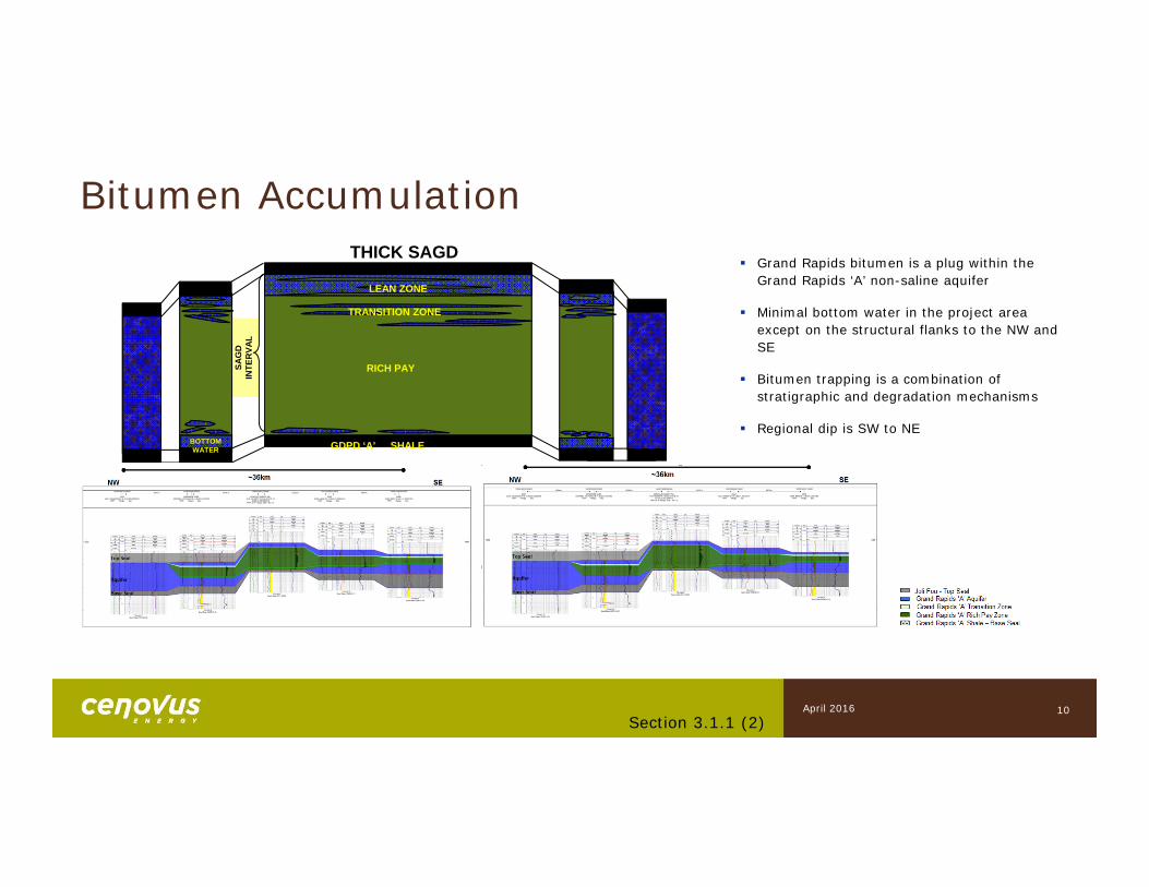
Grand Rapids bitumen is a plug within the Grand Rapids ‘A’ non-saline aquifer
Minimal bottom water in the project area except on the structural flanks to the NW and SE
Bitumen trapping is a combination of stratigraphic and degradation mechanisms
Regional dip is SW to NE
Bitumen Accumulation
10Section 3.1.1 (2)
April 2016
11
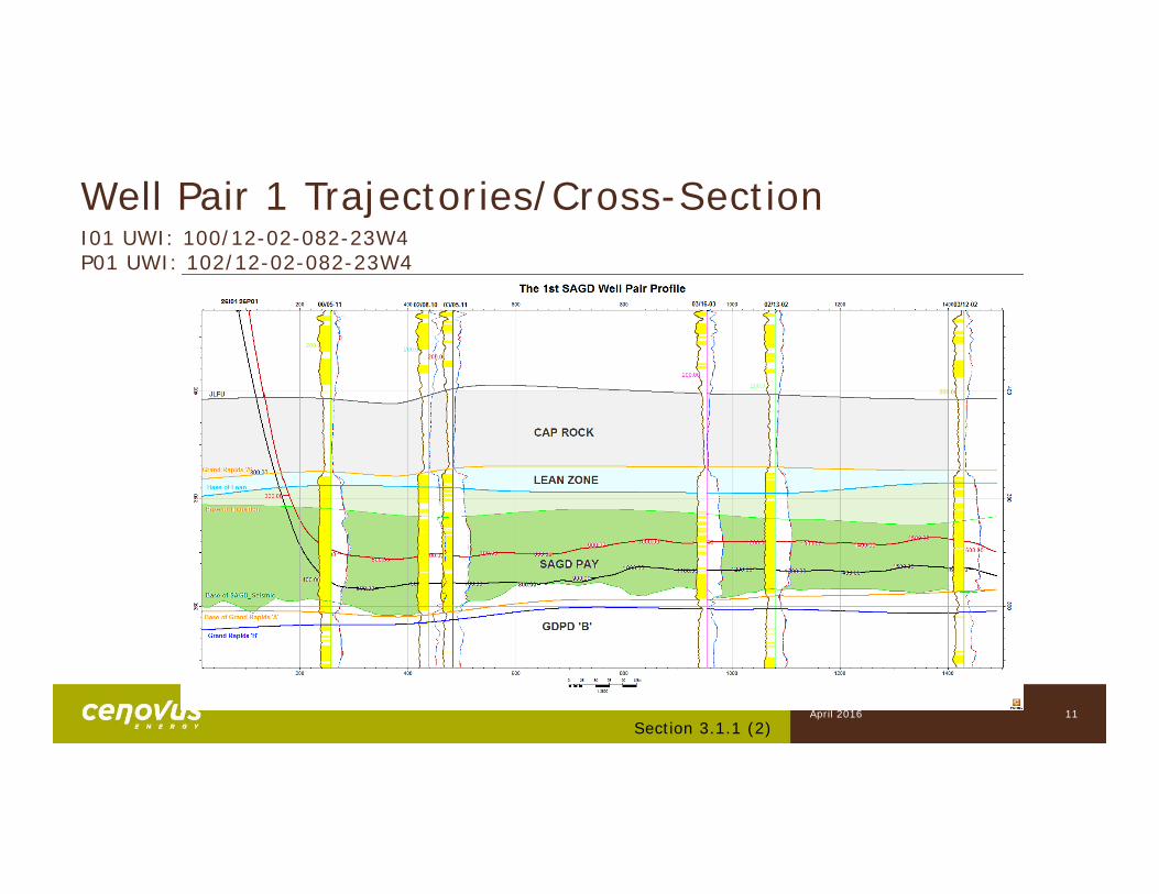
Well Pair 1 Trajectories/Cross-Section
Section 3.1.1 (2)
I01 UWI: 100/12-02-082-23W4P01 UWI: 102/12-02-082-23W4
April 2016
12
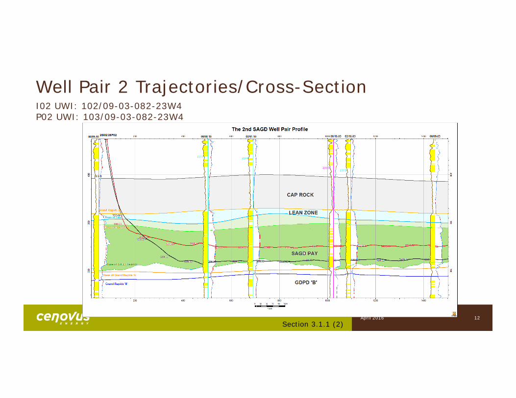
Well Pair 2 Trajectories/Cross-Section
Section 3.1.1 (2)
I02 UWI: 102/09-03-082-23W4P02 UWI: 103/09-03-082-23W4
April 2016
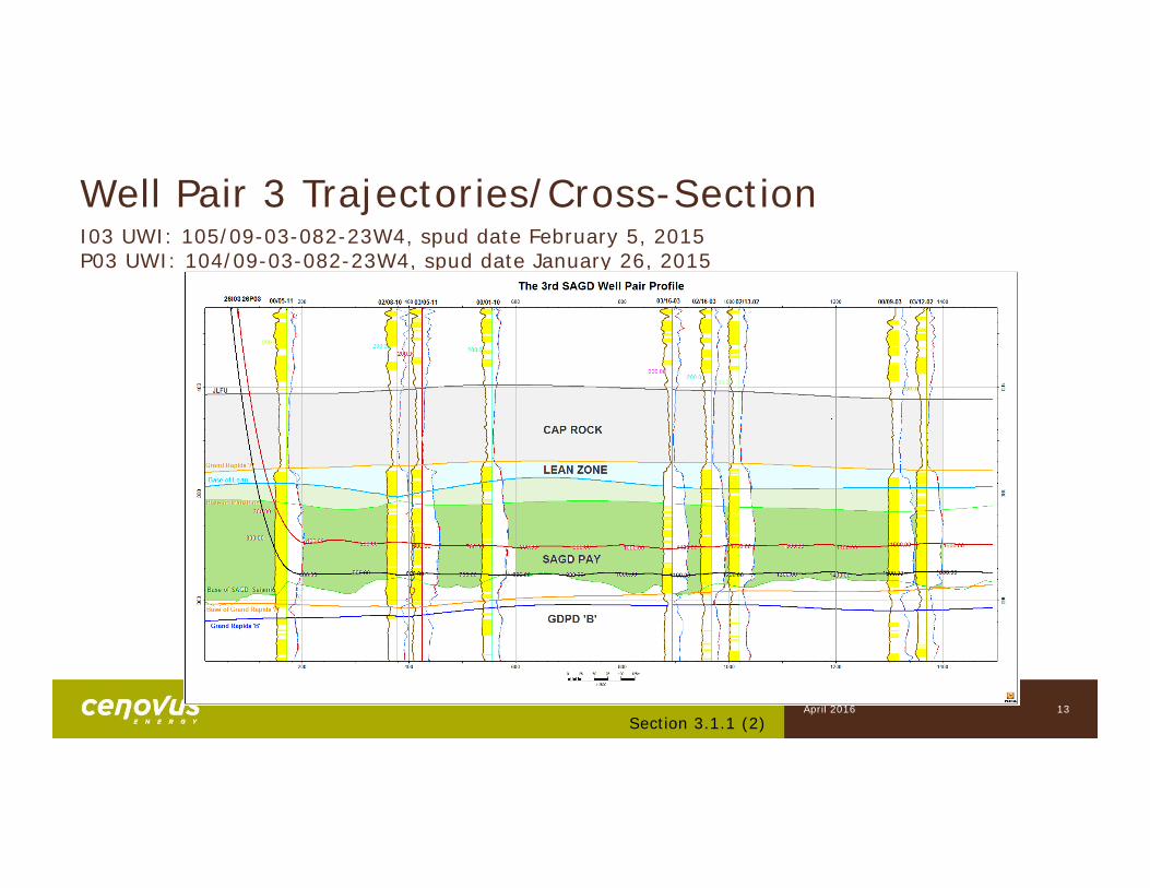
Well Pair 3 Trajectories/Cross-SectionI03 UWI: 105/09-03-082-23W4, spud date February 5, 2015P03 UWI: 104/09-03-082-23W4, spud date January 26, 2015
Section 3.1.1 (2)April 2016 13
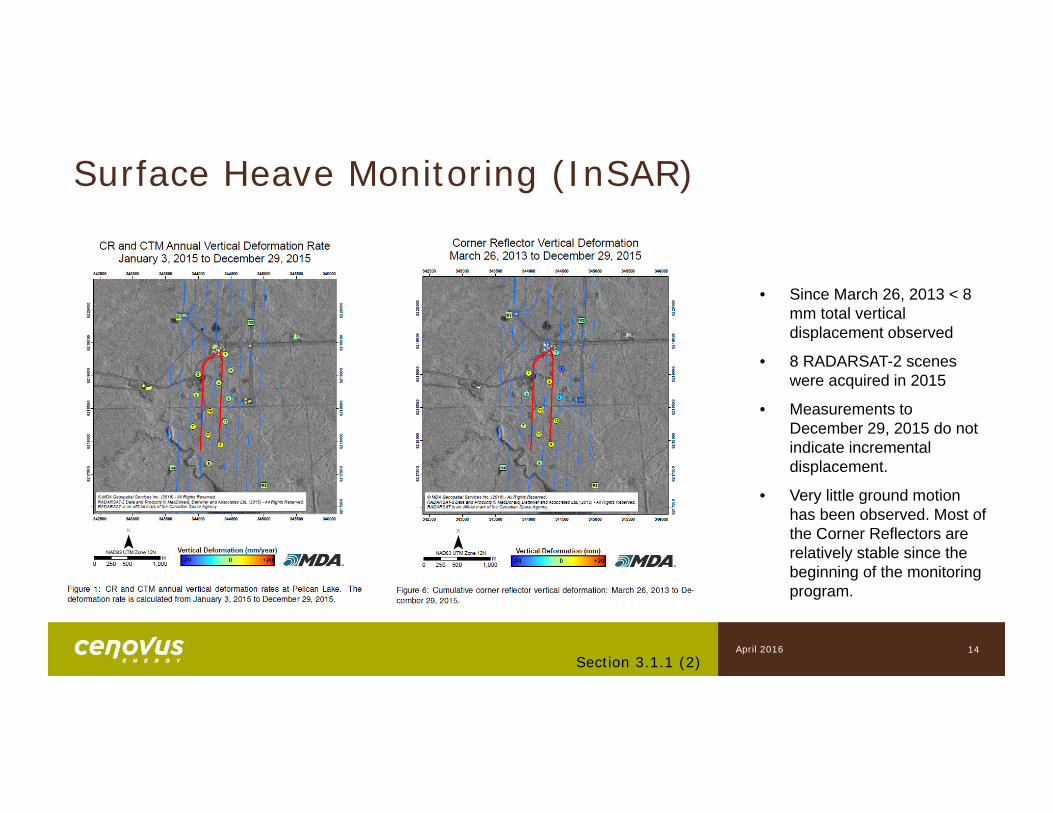
Surface Heave Monitoring (InSAR)
14
• Since March 26, 2013 < 8 mm total vertical displacement observed
• 8 RADARSAT-2 scenes were acquired in 2015
• Measurements to December 29, 2015 do not indicate incremental displacement.
• Very little ground motion has been observed. Most of the Corner Reflectors are relatively stable since the beginning of the monitoring program.
Section 3.1.1 (2)April 2016
15
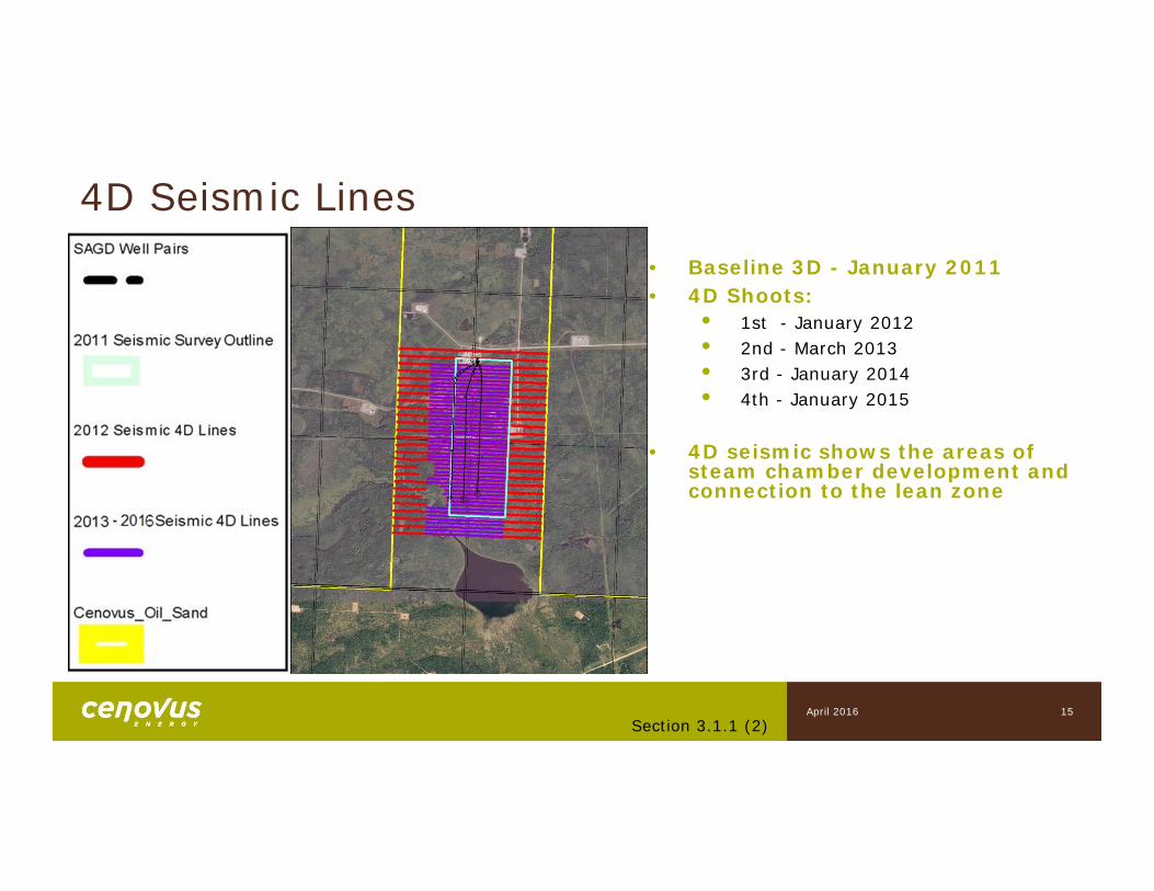
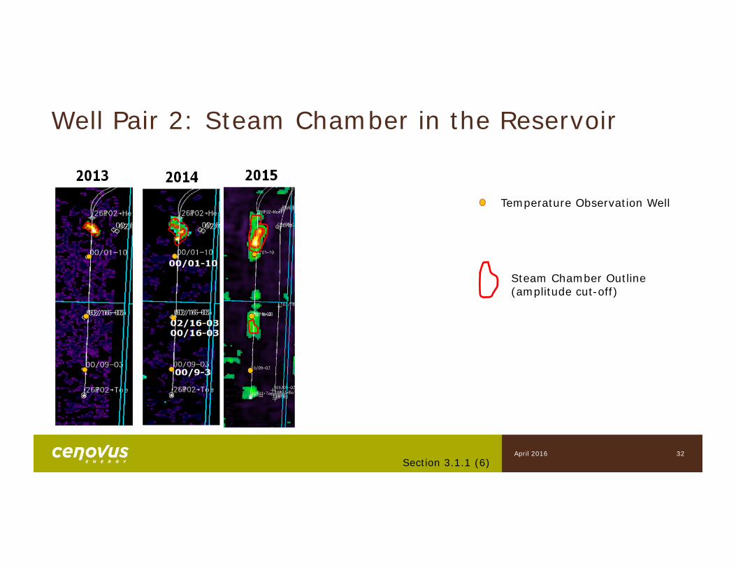
4D Seismic Lines• Baseline 3D - January 2011• 4D Shoots:
• 1st - January 2012• 2nd - March 2013• 3rd - January 2014• 4th - January 2015
• 4D seismic shows the areas of steam chamber development and connection to the lean zone
Section 3.1.1 (2)April 2016
3) Drilling/Completions
Subsection 3.1.1
17
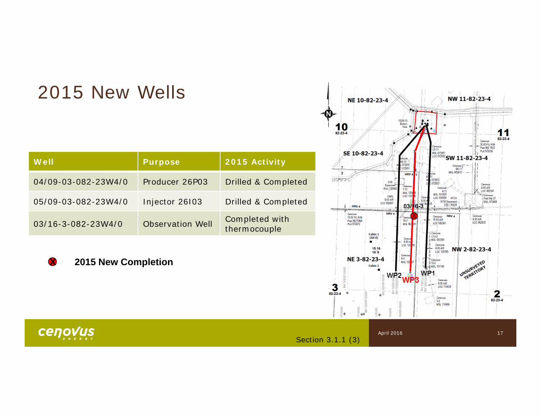
X 2015 New Completion
Well Purpose 2015 Activity
04/09-03-082-23W4/0 Producer 26P03 Drilled & Completed
05/09-03-082-23W4/0 Injector 26I03 Drilled & Completed
03/16-3-082-23W4/0 Observation Well Completed with thermocouple
Section 3.1.1 (3)
2015 New Wells
April 2016
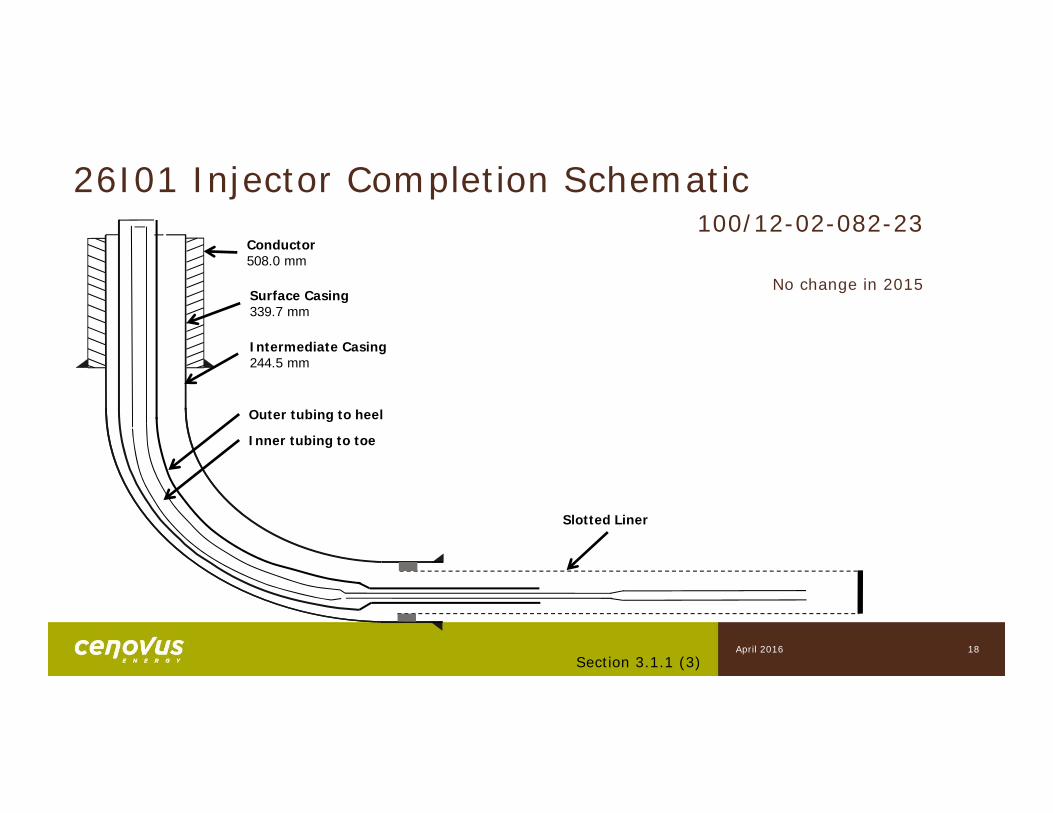
Surface Casing339.7 mm
Intermediate Casing244.5 mm
Inner tubing to toe
Slotted Liner
Outer tubing to heel
Conductor 508.0 mm
26I01 Injector Completion Schematic
18
100/12-02-082-23
No change in 2015
Section 3.1.1 (3)April 2016
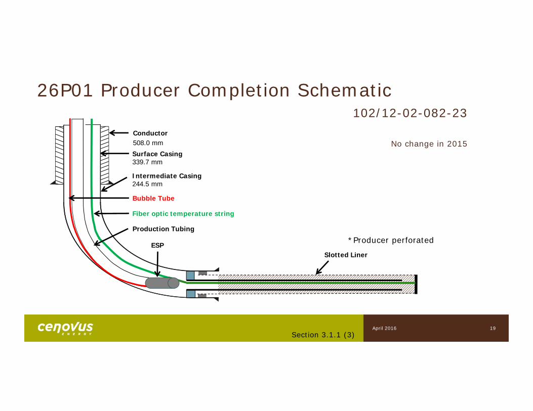
26P01 Producer Completion Schematic
Slotted Liner
Surface Casing339.7 mm
Intermediate Casing244.5 mm
Bubble Tube
Production Tubing
Fiber optic temperature string
ESP
19
102/12-02-082-23
*Producer perforated
Conductor508.0 mm No change in 2015
Section 3.1.1 (3)April 2016
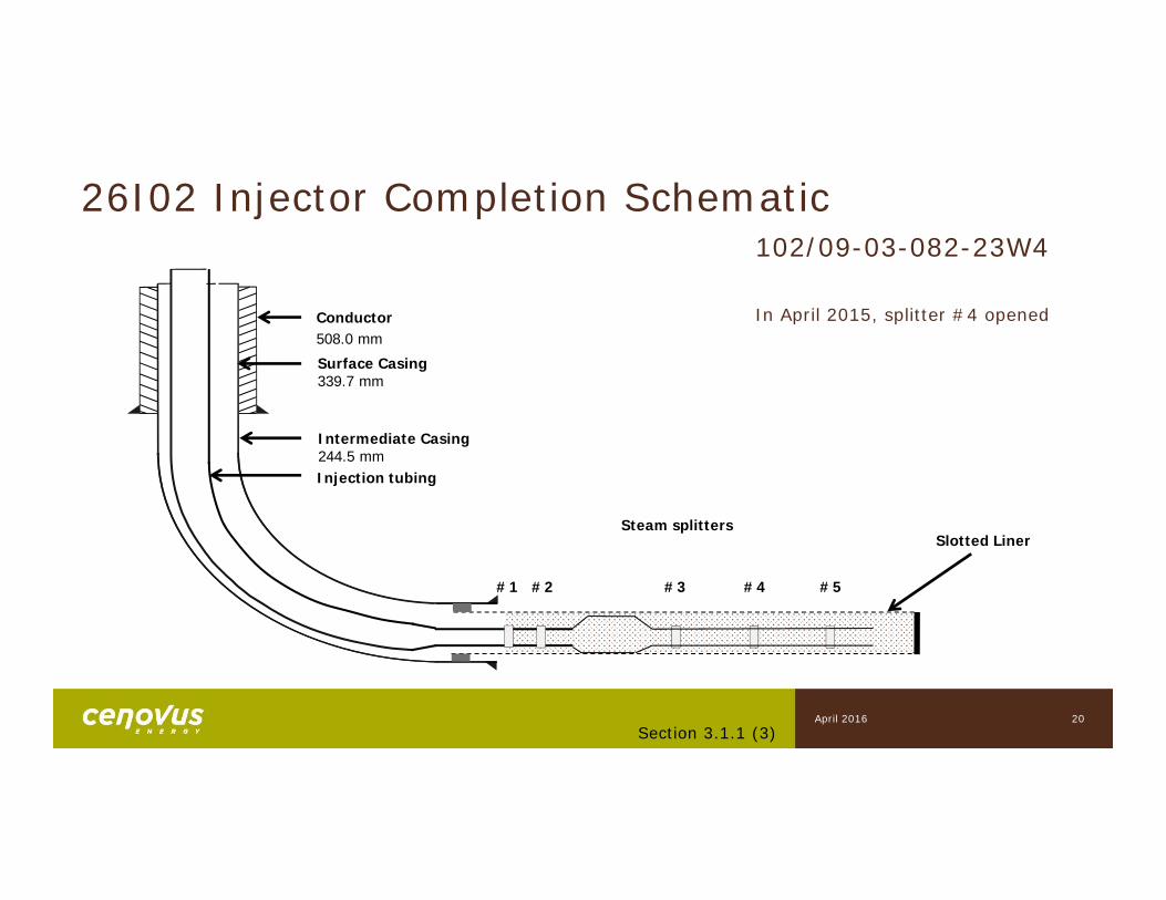
26I02 Injector Completion Schematic
Slotted Liner
Injection tubing
Intermediate Casing244.5 mm
20
102/09-03-082-23W4
Surface Casing339.7 mm
Conductor508.0 mm
#1 #2 #3 #4 #5
Steam splitters
In April 2015, splitter #4 opened
Section 3.1.1 (3)April 2016
Intermediate Casing244.5 mm
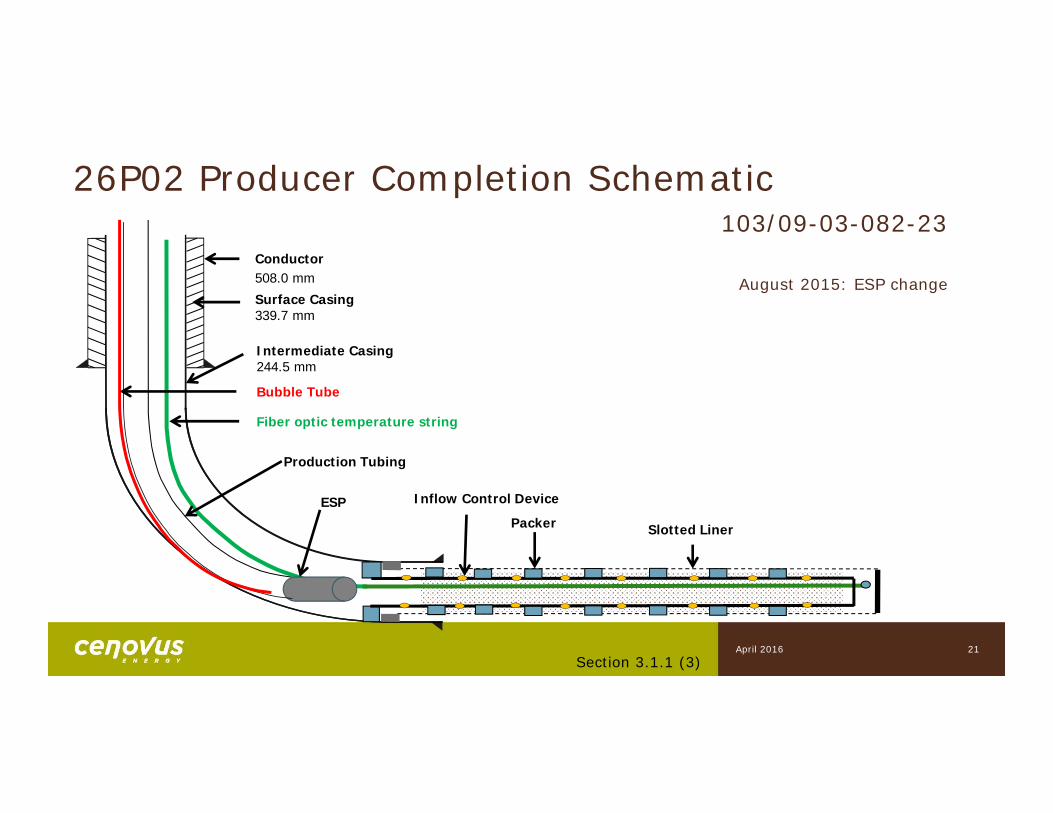
Slotted LinerPacker
Bubble Tube
Production Tubing
ESP Inflow Control Device
Fiber optic temperature string
21
103/09-03-082-23
Surface Casing339.7 mm
Conductor508.0 mm August 2015: ESP change
Section 3.1.1 (3)
26P02 Producer Completion Schematic
April 2016
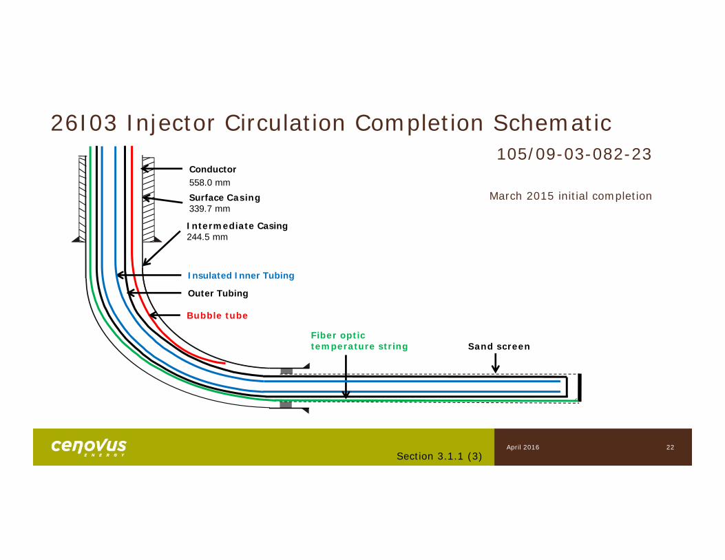
26I03 Injector Circulation Completion Schematic
Fiber optic temperature string
Bubble tube
Insulated Inner Tubing
Surface Casing339.7 mm
Intermediate Casing244.5 mm
Conductor558.0 mm
Outer Tubing
105/09-03-082-23
March 2015 initial completion
Sand screen
22Section 3.1.1 (3)
April 2016
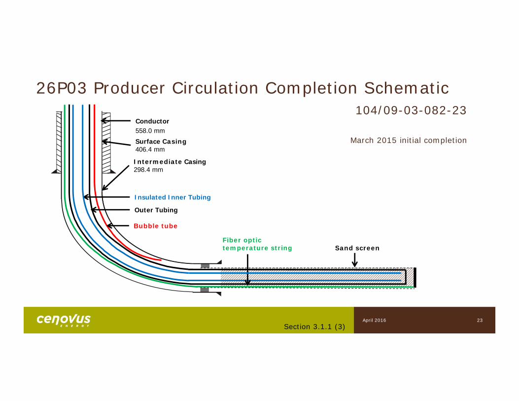
26P03 Producer Circulation Completion Schematic
Fiber optic temperature string
Bubble tube
Insulated Inner Tubing
Surface Casing406.4 mm
Intermediate Casing298.4 mm
Sand screen
Conductor558.0 mm
Outer Tubing
104/09-03-082-23
March 2015 initial completion
23Section 3.1.1 (3)
April 2016
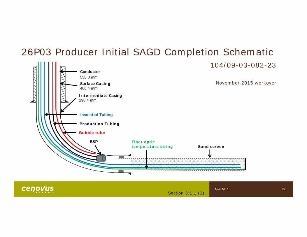
26P03 Producer Initial SAGD Completion Schematic
Fiber optic temperature string
Bubble tube
Production Tubing
ESP
Insulated Tubing
Surface Casing406.4 mm
Intermediate Casing298.4 mm
Sand screen
Conductor558.0 mm
104/09-03-082-23
November 2015 workover
24Section 3.1.1 (3)
April 2016

4) Artificial Lift
Subsection 3.1.1
26
Artificial Lift – 26P01, 26P02, 26P03 SAGD
• All production and source wells use Electric Submersible Pumps (ESPs)
• Pump Sizing Range: 50-350 m3/d• Intake Pump Pressure: 600-1200 kPag (P01, P02), 1,500-2,500 kPag (P03)• Pump Control: Variable Frequency Drives (VFD)• Max Operating Temperature: 218-250°C• Limitations: Low pump efficiency under saturation conditions• Performance monitoring: standard deviation of ESP amp draw, run life
Section 3.1.1 (4)April 2016

5) Well Instrumentation
Subsection 3.1.1
28
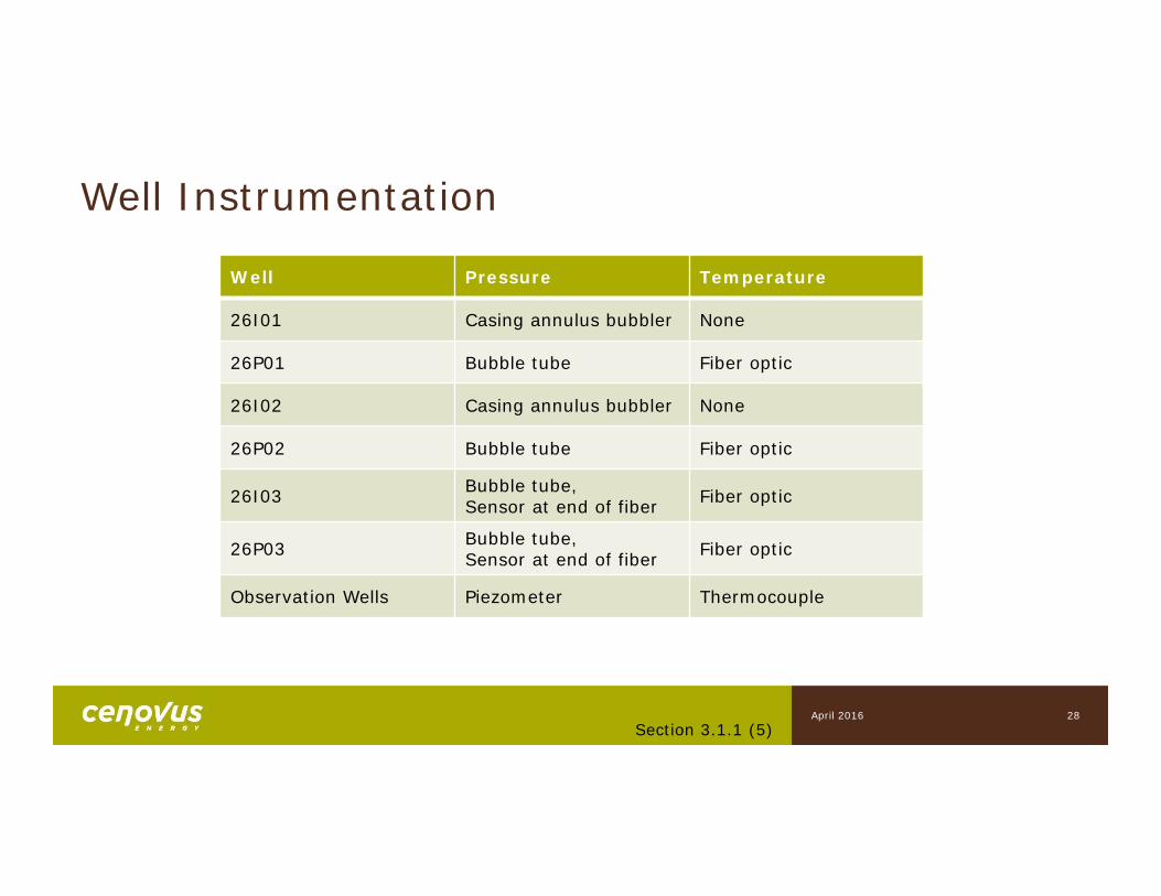
Well Instrumentation
Well Pressure Temperature
26I01 Casing annulus bubbler None
26P01 Bubble tube Fiber optic
26I02 Casing annulus bubbler None
26P02 Bubble tube Fiber optic
26I03 Bubble tube,Sensor at end of fiber Fiber optic
26P03 Bubble tube,Sensor at end of fiber Fiber optic
Observation Wells Piezometer Thermocouple
Section 3.1.1 (5)April 2016
6) 4-D Seismic
Subsection 3.1.1
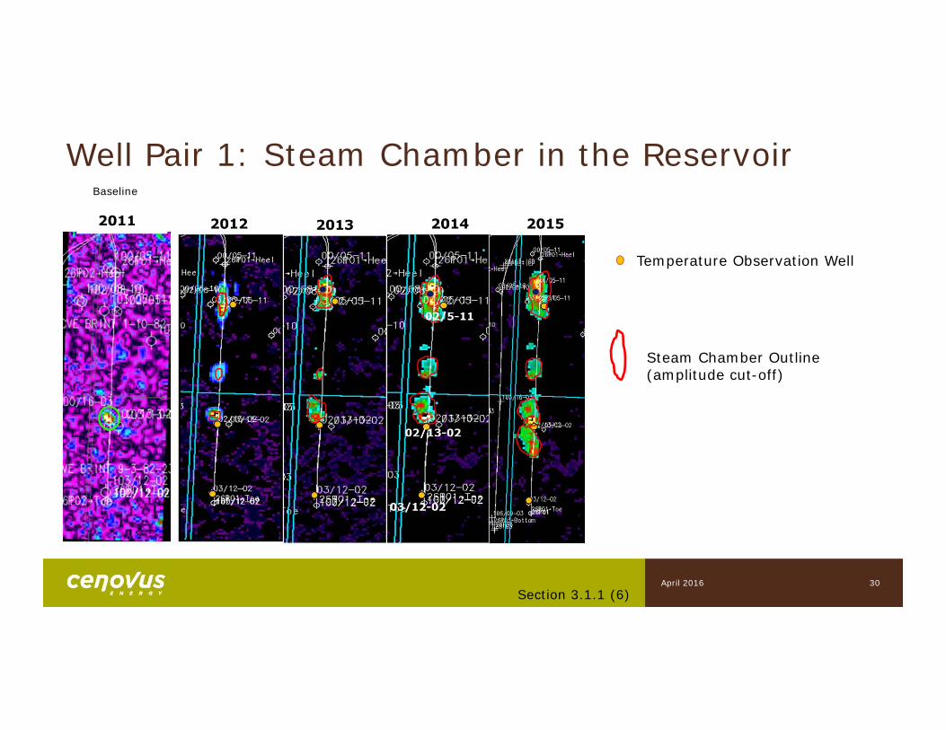
Well Pair 1: Steam Chamber in the Reservoir
Temperature Observation Well
30
Baseline
Steam Chamber Outline(amplitude cut-off)
Section 3.1.1 (6)April 2016
32
Temperature Observation Well
Steam Chamber Outline (amplitude cut-off)
Section 3.1.1 (6)
Well Pair 2: Steam Chamber in the Reservoir
April 2016
7) Scheme PerformanceWell Pair 1
Subsection 3.1.1
33Section 3.1.1 (7)
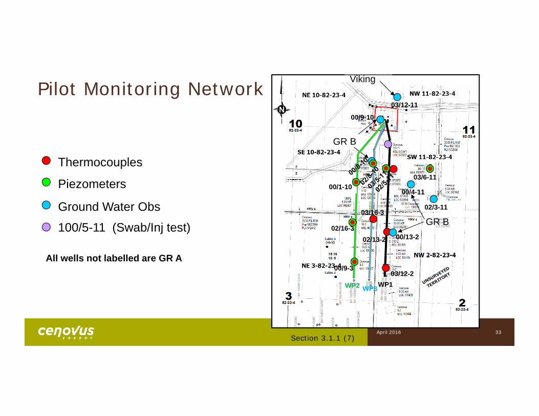
Thermocouples
Piezometers
Ground Water Obs
100/5-11 (Swab/Inj test)
Pilot Monitoring Network
00/5-11
GR A
02/16-3
03/6-11
02/3-11
03/12-2
02/13-2
03/12-11
00/9-10
00/4-11
00/13-2
GR B
Viking
GR B
00/9-3
00/1-10
03/16-3
WP2 WP3WP1
All wells not labelled are GR A
April 2016
34
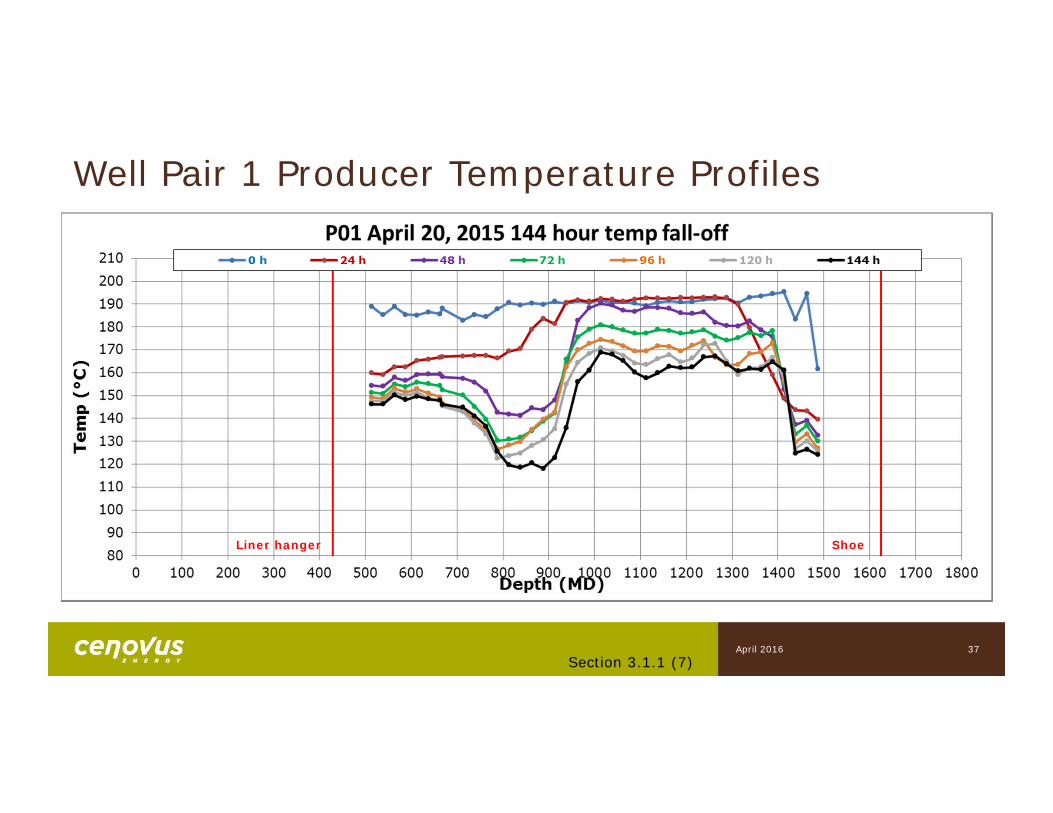
• I01/P01 drawdowns were lower due to P01 perforation in Q4 2014 with no significant sand production issues
• Continued to improve thermal conformance
• Results from six day temperature fall-off in April 2015 (facility turnaround) for 26P01 shows steam chamber growth at the toe
Section 3.1.1 (7)
Well Pair 1: 2015 Summary
April 2016
Section 3.1.1 (7)35
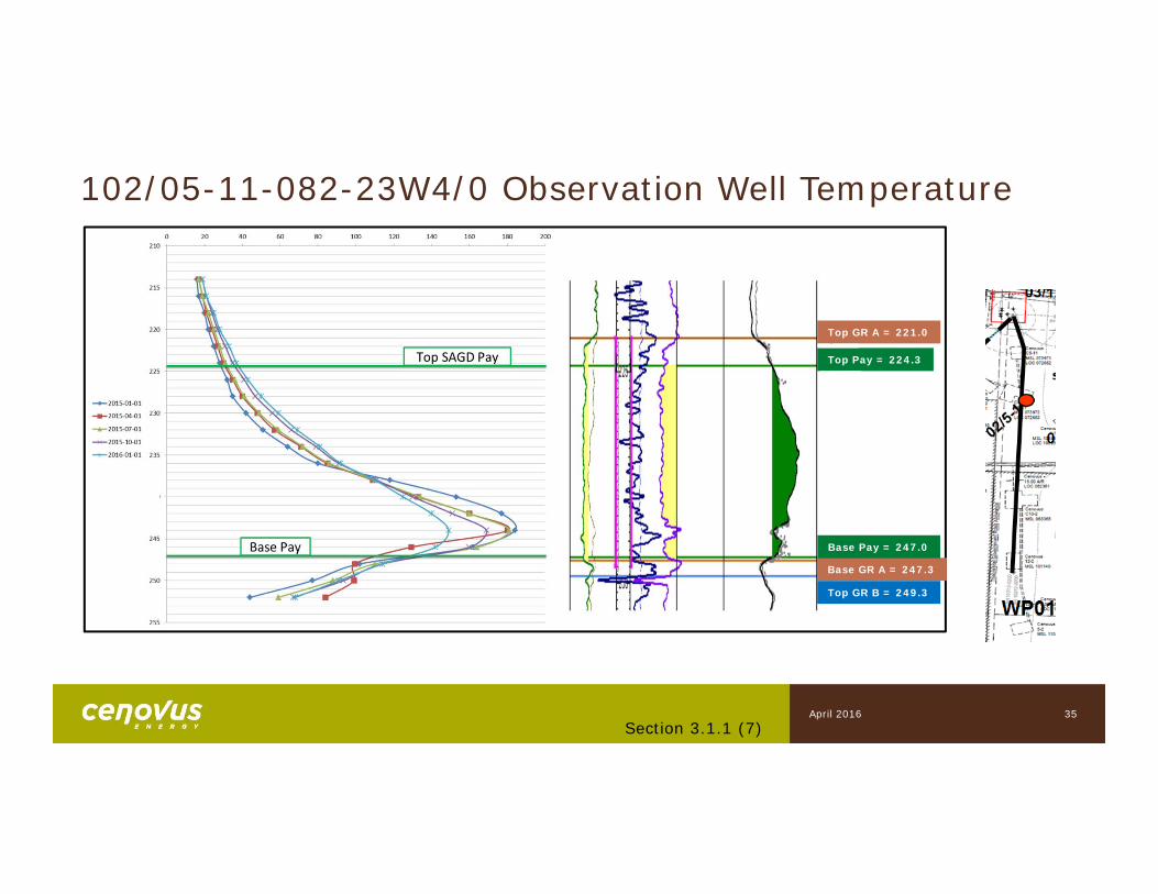
Top GR A = 221.0
Base GR A = 247.3
Base Pay = 247.0
Top Pay = 224.3
Top GR B = 249.3
102/05-11-082-23W4/0 Observation Well Temperature
April 2016
36Section 3.1.1 (7)
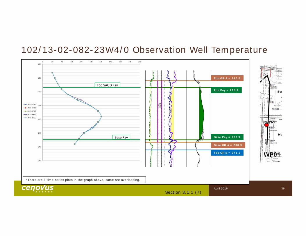
*There are 5 time-series plots in the graph above, some are overlapping.
Base GR A = 238.3
Base Pay = 237.3
Top GR B = 241.1
102/13-02-082-23W4/0 Observation Well Temperature
Top GR A = 216.0
Top Pay = 218.4
April 2016
37Section 3.1.1 (7)
Liner hanger
Well Pair 1 Producer Temperature Profiles
Shoe
April 2016
38Section 3.1.1 (7)
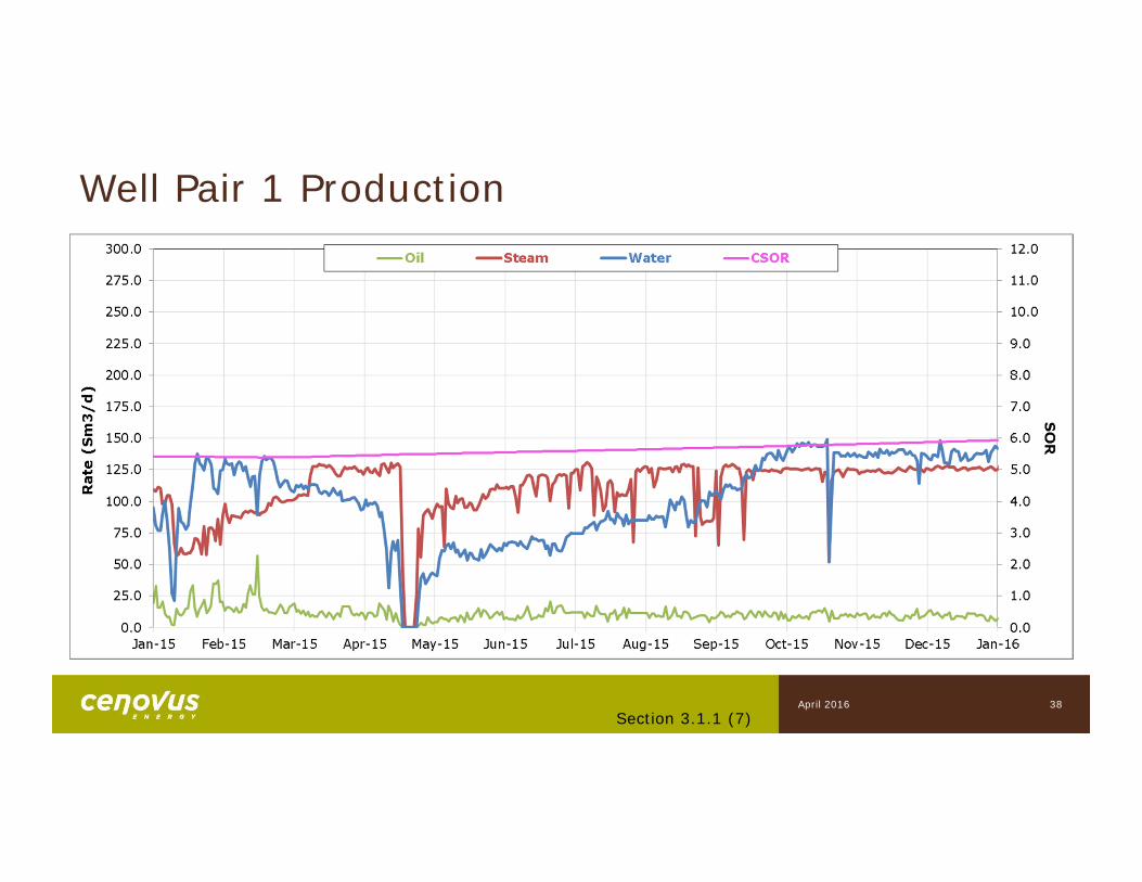
Well Pair 1 Production
April 2016

7) Scheme PerformanceWell Pair 2
Subsection 3.1.1

40
Well Pair 2: 2015 Summary
• Successful workover in April 2015 to open a shiftable steam splitter
• Sought to maintain pressure balance with lean zone
• Continued to improve thermal conformance
• Continued to evaluate effect of steam splitter shift and tubing-deployed Inflow Control Devices (ICDs) installed in P02
Section 3.1.1 (7)April 2016
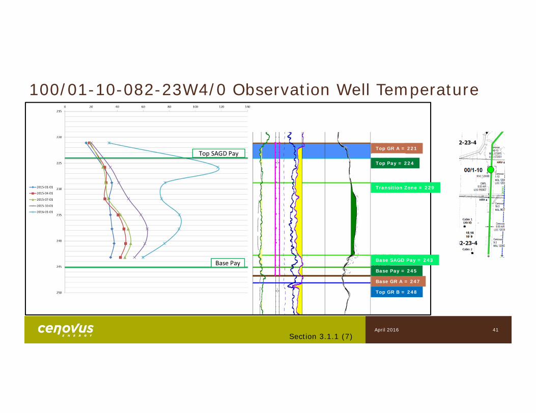
100/01-10-082-23W4/0 Observation Well Temperature
41Section 3.1.1 (7)
Top GR A = 221
Base GR A = 247
Base Pay = 245
Top Pay = 224
Top GR B = 248
Transition Zone = 229
Base SAGD Pay = 243
April 2016
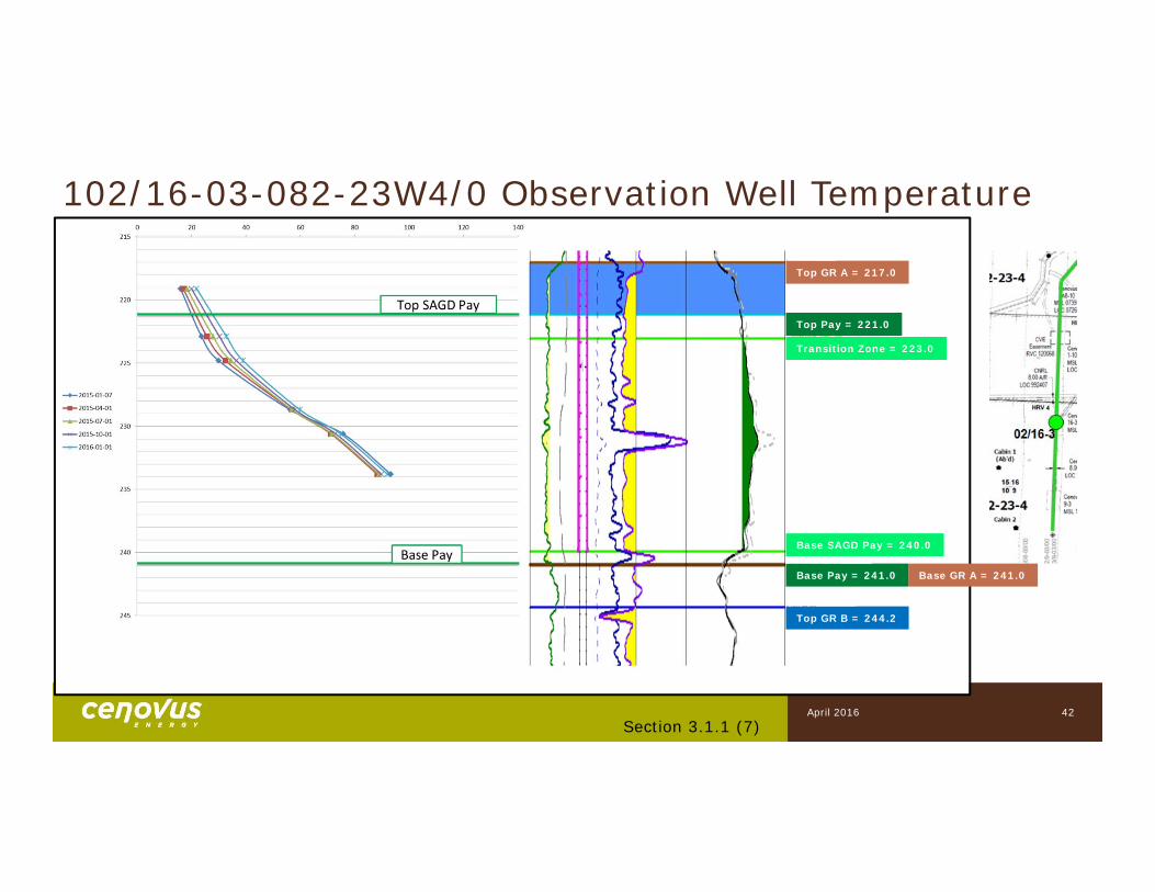
102/16-03-082-23W4/0 Observation Well Temperature
Section 3.1.1 (7)42
Top GR A = 217.0
Base GR A = 241.0Base Pay = 241.0
Top Pay = 221.0
Top GR B = 244.2
Transition Zone = 223.0
Base SAGD Pay = 240.0
April 2016
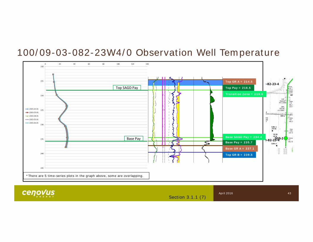
100/09-03-082-23W4/0 Observation Well Temperature
43Section 3.1.1 (7)
*There are 5 time-series plots in the graph above, some are overlapping.
Top GR A = 214.5
Base GR A = 237.1
Base Pay = 235.7
Top Pay = 216.5
Top GR B = 239.5
Transition Zone = 218.0
Base SAGD Pay = 234.4
April 2016
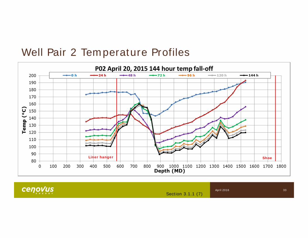
Well Pair 2 Temperature Profiles
Section 3.1.1 (7)33
Liner hanger Shoe
April 2016
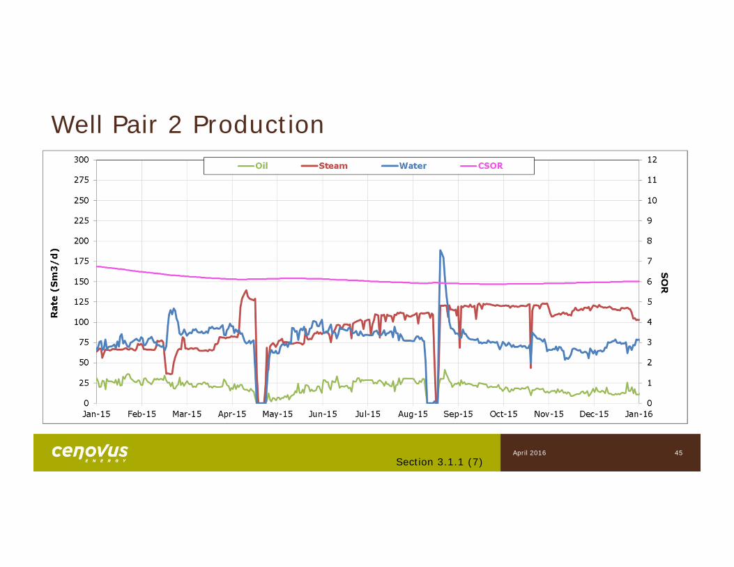
Well Pair 2 Production
45Section 3.1.1 (7)
April 2016
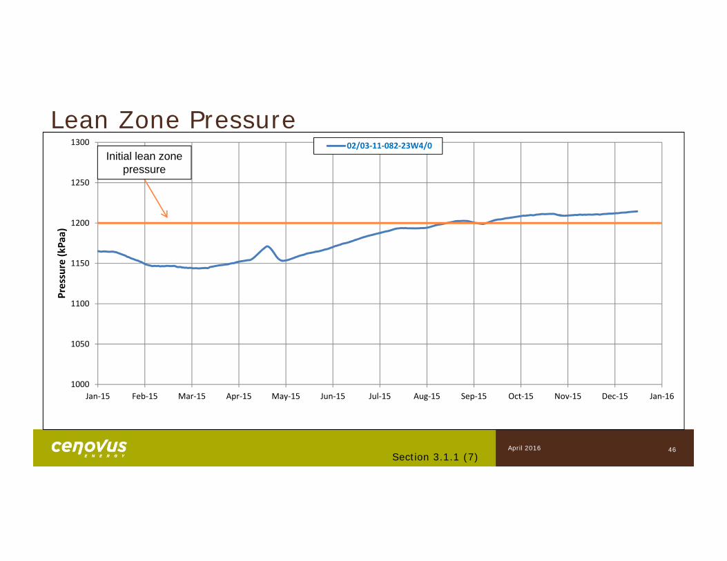
1000
1050
1100
1150
1200
1250
1300
Jan‐15 Feb‐15 Mar‐15 Apr‐15 May‐15 Jun‐15 Jul‐15 Aug‐15 Sep‐15 Oct‐15 Nov‐15 Dec‐15 Jan‐16
Pressure (k
Paa)
02/03‐11‐082‐23W4/0
46
Lean Zone PressureInitial lean zone
pressure
Section 3.1.1 (7)April 2016

7) Scheme PerformanceWell Pair 3
Subsection 3.1.1
48
Well Pair 3 Startup
Description• Proprietary Closed Circuit conductive heating startup (patent pending)• Permits operation at higher temperatures compared with existing circulation
practice• Promotes uniform temperature distribution along lateral
Timeline• 26P03 and 26I03 initial completions in February 2015• 26P03 began circulation May 4, 2015• 26I03 began circulation June 9, 2015• 26P03 converted to SAGD mode November 18, 2015
Section 3.1.1 (7)April 2016
49
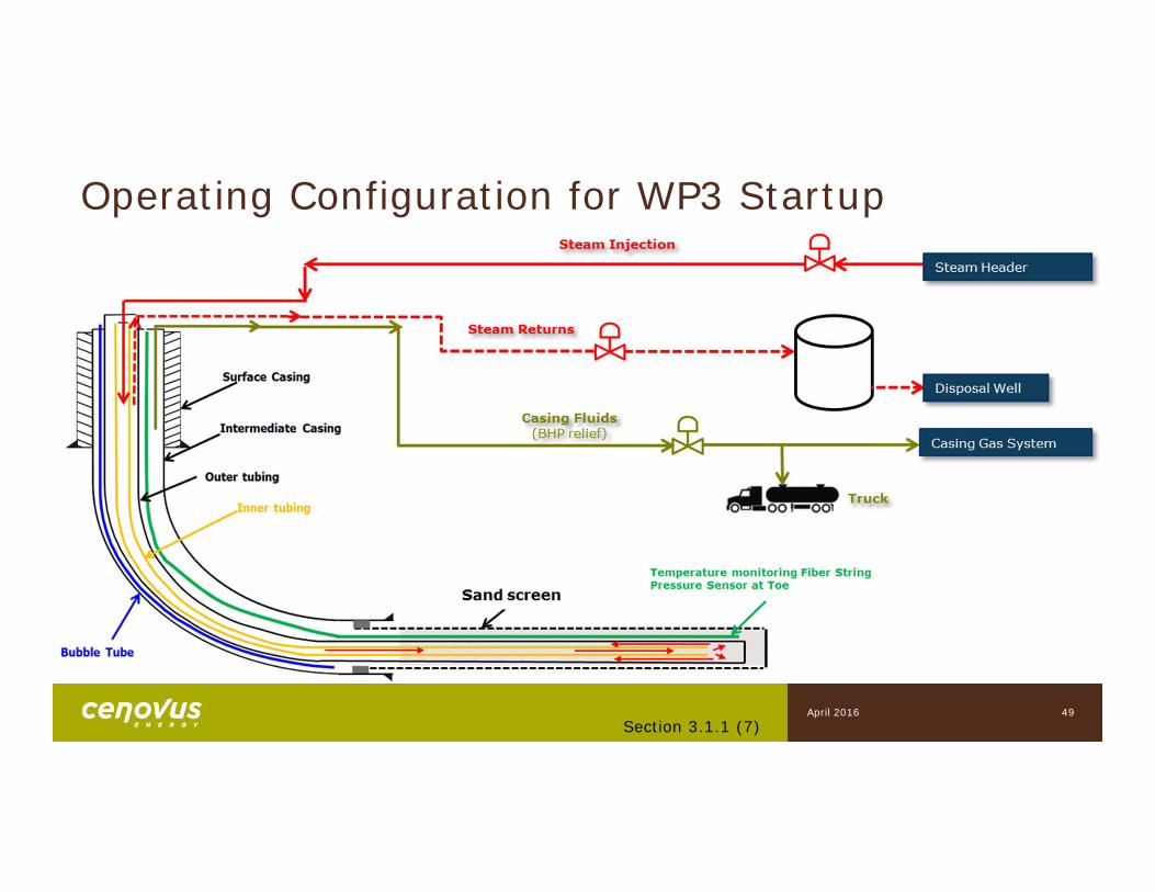
Operating Configuration for WP3 Startup
Section 3.1.1 (7)April 2016
50Section 3.1.1 (7)
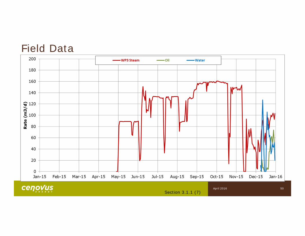
Field Data
April 2016
51
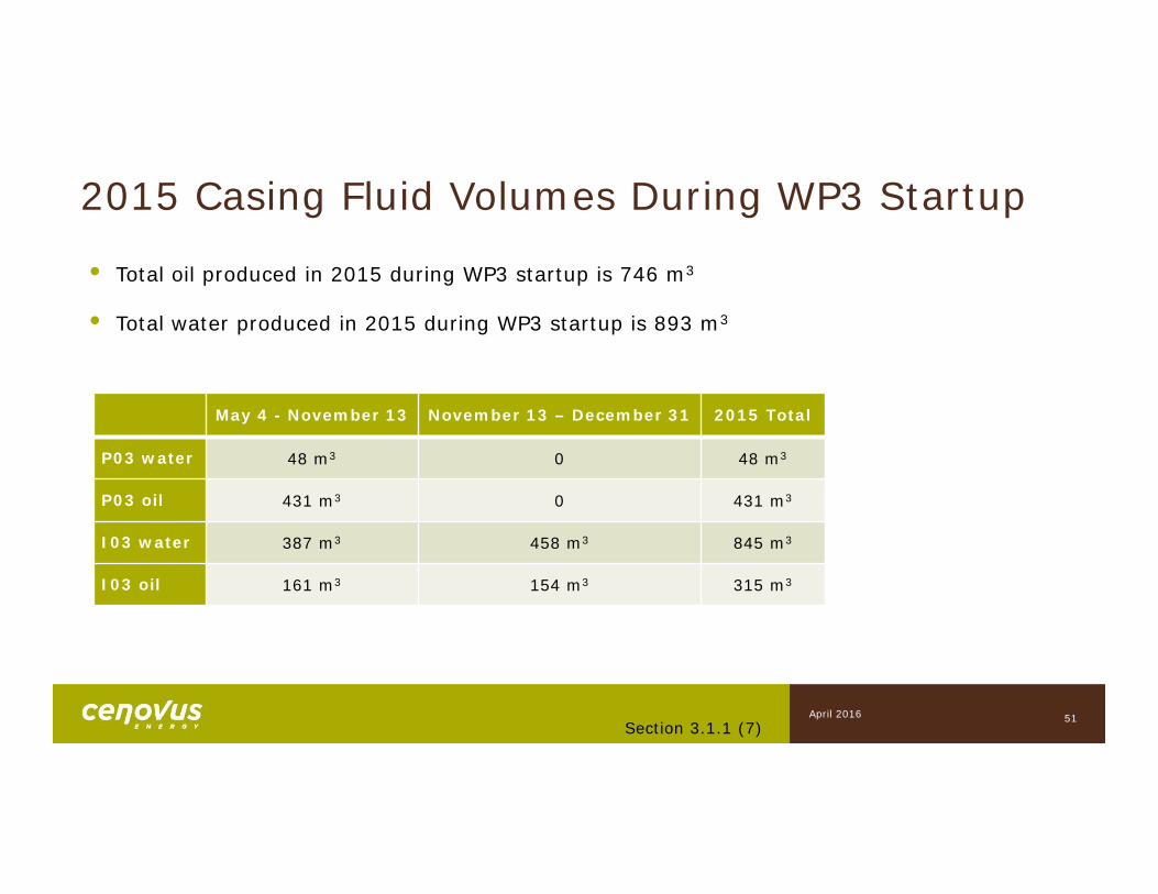
May 4 - November 13 November 13 – December 31 2015 Total
P03 water 48 m3 0 48 m3
P03 oil 431 m3 0 431 m3
I03 water 387 m3 458 m3 845 m3
I03 oil 161 m3 154 m3 315 m3
• Total oil produced in 2015 during WP3 startup is 746 m3
• Total water produced in 2015 during WP3 startup is 893 m3
Section 3.1.1 (7)
2015 Casing Fluid Volumes During WP3 Startup
April 2016
Section 3.1.1 (7)52
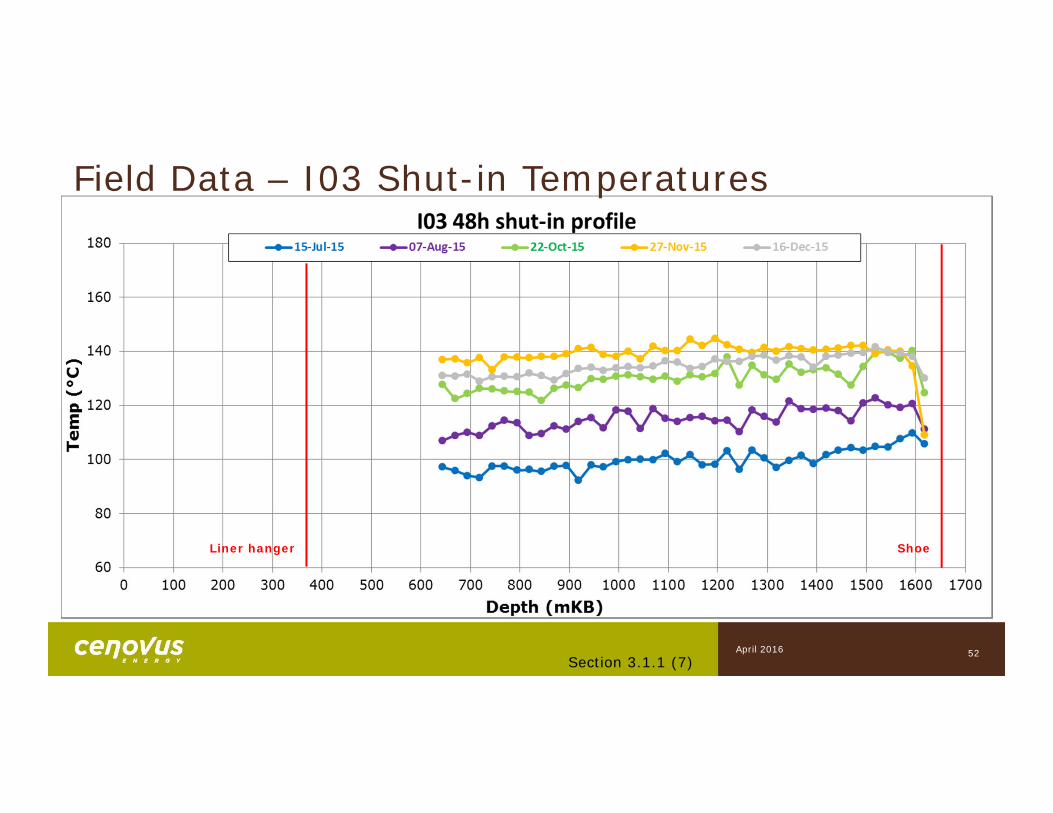
Field Data – I03 Shut-in Temperatures
Liner hanger Shoe
April 2016
Section 3.1.1 (7)53
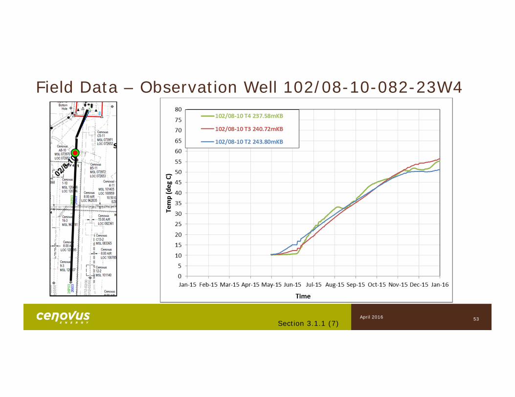
Field Data – Observation Well 102/08-10-082-23W4
April 2016
54
WP3 Startup Learnings
• Operated at higher temperatures compared with existing circulation practice
• Achieved uniform temperature distribution along lateral
• Fluids were produced as a result of bottomhole fluid expansion
• Temperature profiles, wellbore dynamics, and pace of heating within design expectations
Section 3.1.1 (7)April 2016

8) Future Plans
Subsection 3.1.1
• Temporary suspension of SAGD pilot in Q1 2016
• No drilling plans for 2016
56
Future Plans
Section 3.1.1 (8)April 2016
Surface Operations, Compliance, Non-Related Resource Evaluation Issues
Subsection 3.1.2

1) Facilities
Subsection 3.1.2
59Section 3.1.2 (1)
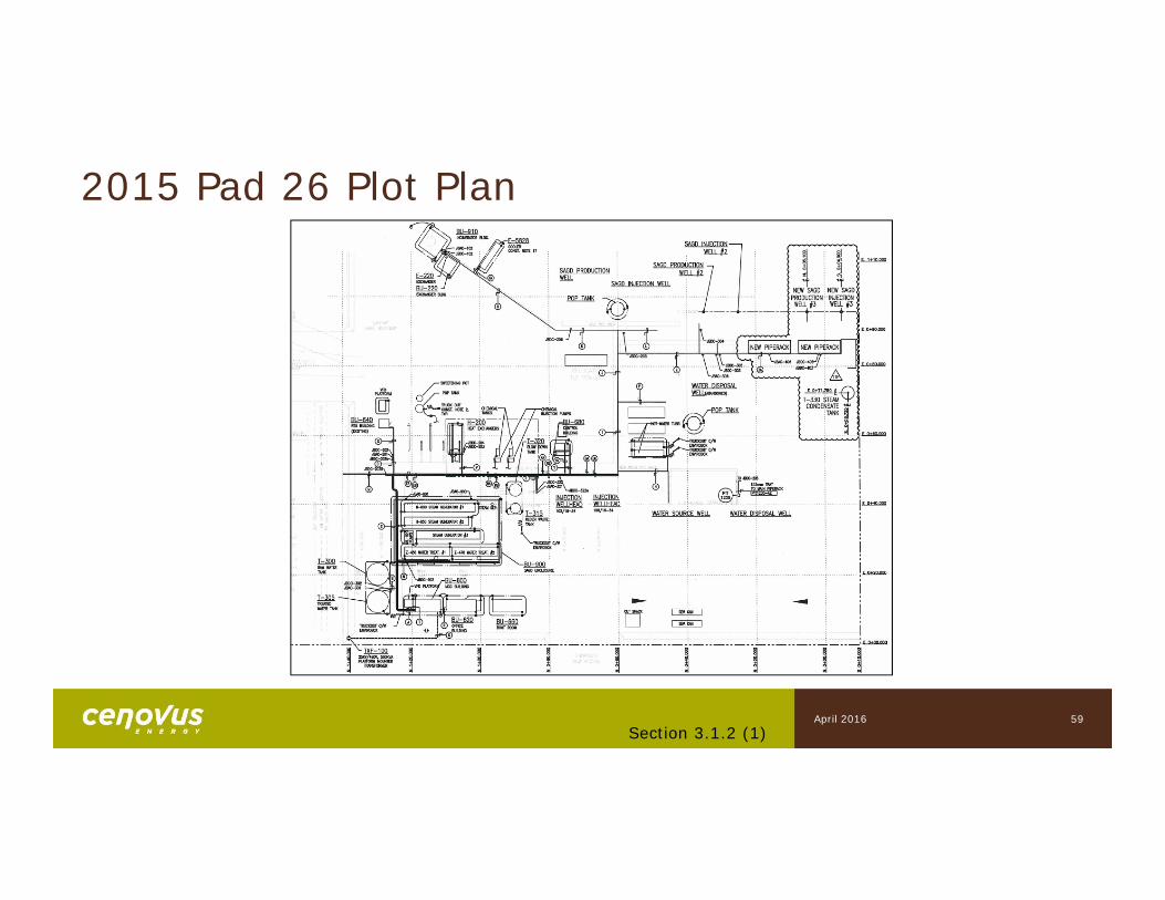
2015 Pad 26 Plot Plan
April 2016
60
2015 Facility SummaryFacility Updates• Completed 26I03 and 26P03 facility tie-ins• Added temporary steam condensate returns tank (T-330) for WP3 startup• Flue gas O2 analyzers installed in the radiant section of two of the OTSGs (H-
800 and H-850) to improve combustion efficiency• No major changes to existing facility
Section 3.1.2 (1)
Plant Performance• Annual plant turnaround executed April 19-27• No lost production exceeding 1 day from unplanned plant outages• Steam quality at the injection wellheads estimated at 95-99%• Flue gas O2 Analyzers have not been installed long enough to quantify the
improved boiler controls
April 2016

2) Measurement and Reporting
Subsection 3.1.2
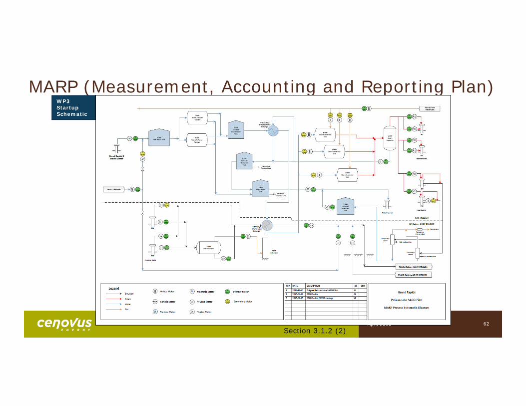
MARP (Measurement, Accounting and Reporting Plan)
62
WP3 Startup Schematic
Section 3.1.2 (2)April 2016
63
Measurement and reportingEstimated well production (oil and water)• Coriolis meters have proven to be effective measurement tools at the pad• 26P02 & 26P03 oil production is estimated by applying manual wellhead cuts to measured
fluid production• 26P01 oil production is estimated by applying manual wellhead cuts to measurement by
difference:
• 26P01 fluid = Pad 26 total fluid – 26P02 fluid – 26P03 (SAGD) fluid• Produced oil and water is transferred to Pelican Lake 11-7 battery (AB BT0058285) for
separation and all produced water is used for injection within scheme approval no. 9404V
Estimated well production (gas)• Total gas production is obtained from a meter measuring the amount of produced gas going
to the incinerator• Gas proration for each production well is calculated using the gas-steam ratio determined
from partial pressures
Section 3.1.2 (2)April 2016
64
Proration Factor• Proration Factor reported to Petrinex on a monthly basis
• Proration Factor (PF) for oil & water = Total pad productionP01 + P02 + P03 production
Meter Calibration• Annual MARP meter calibrations were completed in Q3 2015, as per D017
requirements
Measurement and reporting (continued)
April 2016Section 3.1.2 (2)
65
Water Balance
Section 3.1.2 (2)
GR Battery (AB BT 0113349)In:
• Produced water (26P01, 26P02, 26P03)• Pad 9 source water for quench (1F1/13-07-082-22W4/0)• Pelican Lake produced water for quench (AB BT 0058285)• WP3 startup steam condensate• WP3 casing fluid returns
Out:• Produced/quench water to Pelican Lake (AB BT 0058285)• WP3 startup steam condensate to T-330 (AB IF 0112734)• Truck out (WP3 casing fluid returns)
April 2016
66
Water BalanceInjection Facility (AB IF 0112734)In:
• Inventory open• Source water (1F1/01-15-082-23W4/0)• Source water (1F1/13-07-082-22W4/0) [upset conditions]• Truck in [upset conditions]
Out:• Inventory close• Disposal (regen waste, boiler blowdown, T-330 WP3 startup steam
condensate)• Steam injection (26I01, 26I02, 26I03, 26P03)• Truck out [upset conditions]
Section 3.1.2 (2)April 2016
67
Gas Balance
Section 3.1.2 (2)
GR Battery (AB BT 0113349)In:
• Produced gas (26P01, 26P02, 26P03, 26I03)Out:
• Produced gas to incinerator• Vent to atmosphere (WP3 startup)
Injection Facility (AB IF 0112734)In:
• Fuel gas from TCPL via Pelican Lake main gas line (AB MS 00094854)Out:
• Fuel gas to OTSGs• Fuel gas to incinerator
April 2016
3) Fresh and Brackish Water
Subsection 3.1.2
Water Source Wells
• Source water from Grand Rapids B water well (1F1/01-15-082-23W4/0) is used to generate steam for injection wells
• Source water from Grand Rapids B water well (1F1/13-07-082-22W4/0) is used for management of emulsion temperature in pipelines and primary source water upsets
• No brackish water wells
69Section 3.1.2 (3)
April 2016
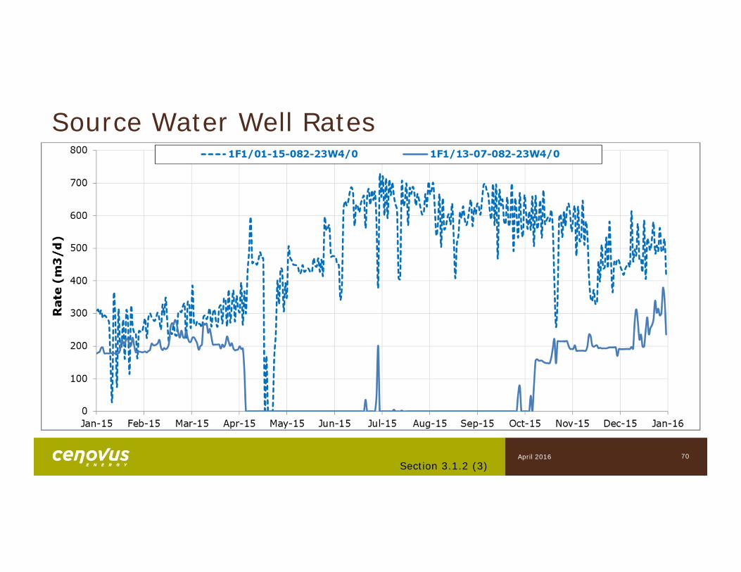
Source Water Well Rates
70Section 3.1.2 (3)
April 2016

4) Water Treatment Technology
Subsection 3.1.2
Water Treatment Overview• Media Filtering
• Primary Strong Acid Cation (SAC) Exchange
• Secondary SAC polisher
• Source water for brine regeneration
• Low concentrations of Acid Producing Bacteria (APB) were identified in the sand filters in December 2015
Section 3.1.2 (4)72April 2016

5) Waste Disposal
Subsection 3.1.2
74
Disposal
• Disposed fluids injected into a Class 1B disposal well (102/09-10-082-23W4/0)
• Disposed fluids include boiler blowdown, ion exchange regeneration waste, and WP3 steam condensate
Section 3.1.2 (5)April 2016
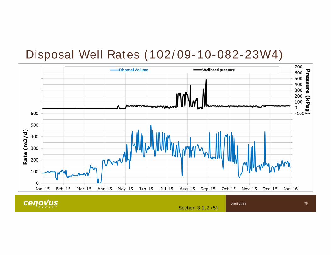
Disposal Well Rates (102/09-10-082-23W4)
Section 3.1.2 (5)75April 2016

6) Air Emissions
Subsection 3.1.2
77
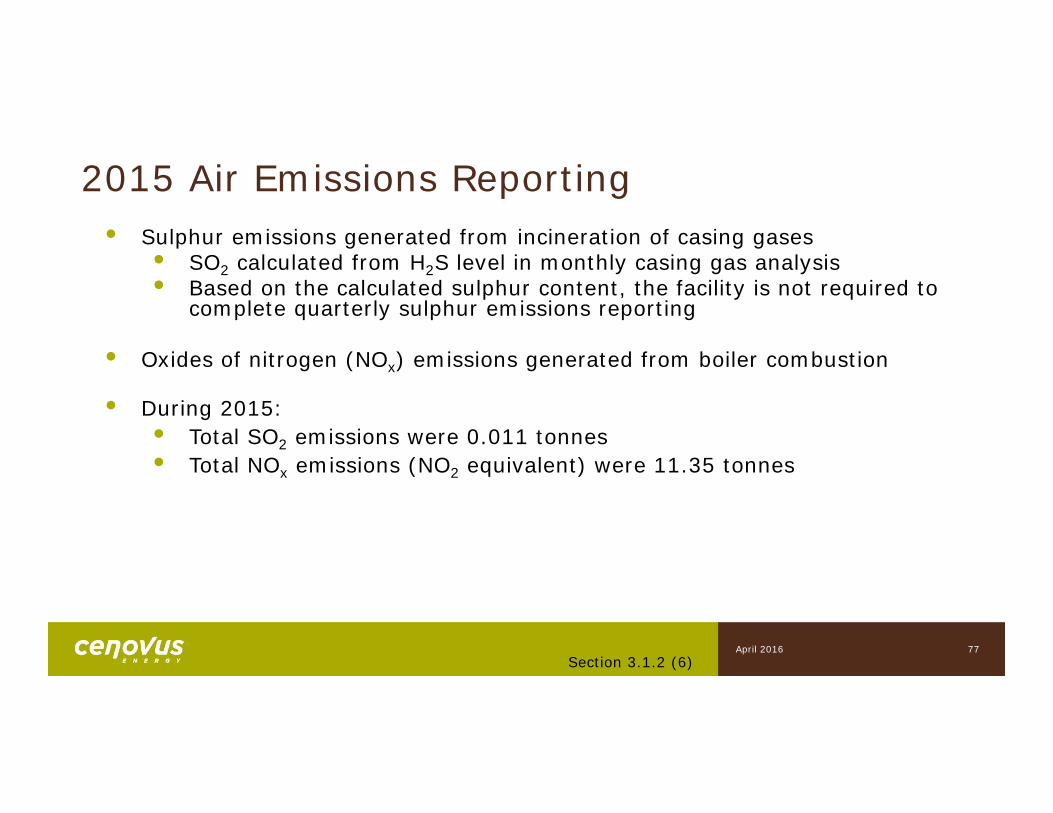
2015 Air Emissions Reporting• Sulphur emissions generated from incineration of casing gases
• SO2 calculated from H2S level in monthly casing gas analysis• Based on the calculated sulphur content, the facility is not required to
complete quarterly sulphur emissions reporting
• Oxides of nitrogen (NOx) emissions generated from boiler combustion
• During 2015:• Total SO2 emissions were 0.011 tonnes• Total NOx emissions (NO2 equivalent) were 11.35 tonnes
Section 3.1.2 (6)April 2016

7-9) Environmental & Compliance
Subsection 3.1.2

79
Environmental Summary
• No environmental events to report
Section 3.1.2 (7)April 2016
80
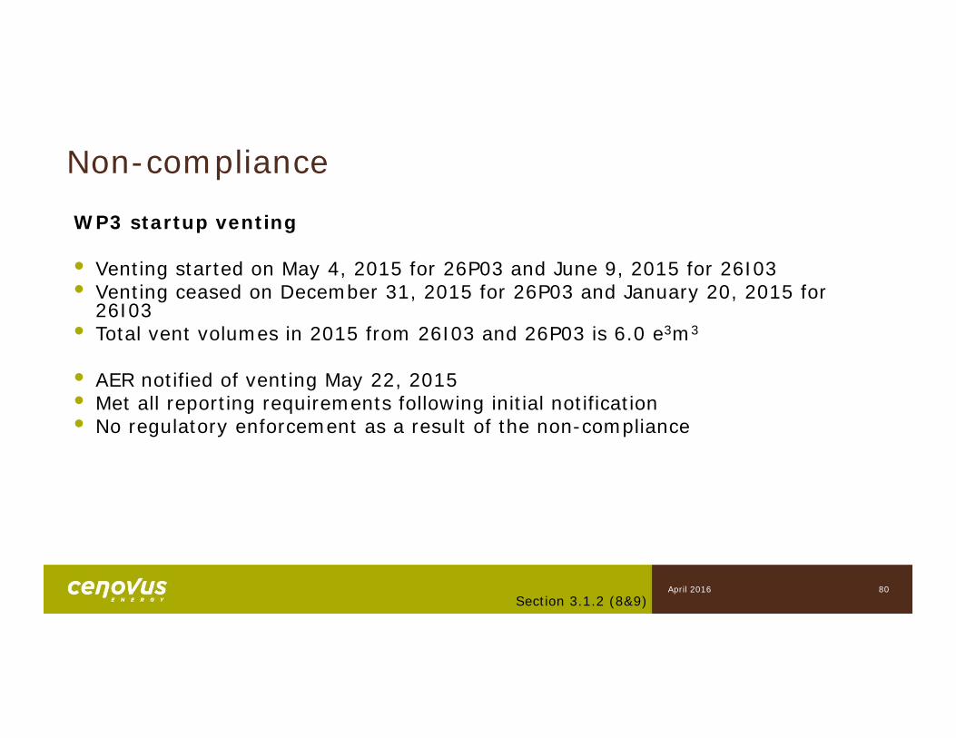
Non-compliance
WP3 startup venting
• Venting started on May 4, 2015 for 26P03 and June 9, 2015 for 26I03• Venting ceased on December 31, 2015 for 26P03 and January 20, 2015 for
26I03• Total vent volumes in 2015 from 26I03 and 26P03 is 6.0 e3m3
• AER notified of venting May 22, 2015• Met all reporting requirements following initial notification• No regulatory enforcement as a result of the non-compliance
Section 3.1.2 (8&9)April 2016

10) Future Plans
Subsection 3.1.2
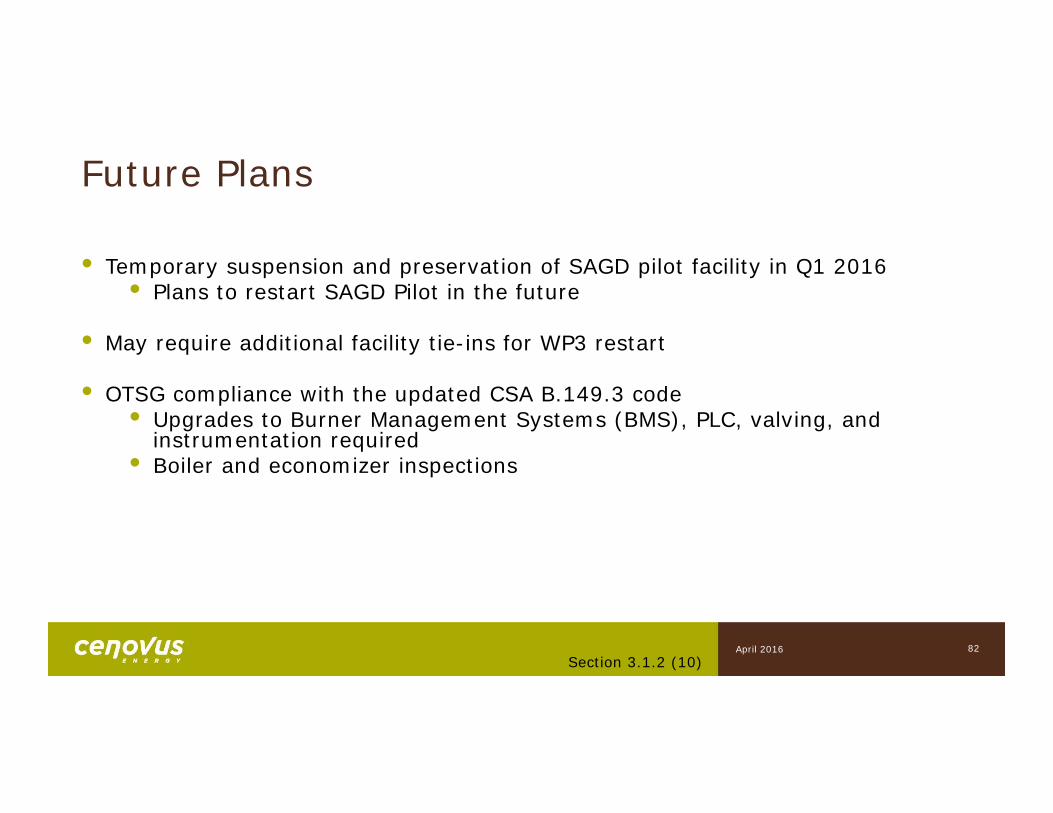
Future Plans
• Temporary suspension and preservation of SAGD pilot facility in Q1 2016• Plans to restart SAGD Pilot in the future
• May require additional facility tie-ins for WP3 restart
• OTSG compliance with the updated CSA B.149.3 code• Upgrades to Burner Management Systems (BMS), PLC, valving, and
instrumentation required• Boiler and economizer inspections
Section 3.1.2 (10)82April 2016

Appendices
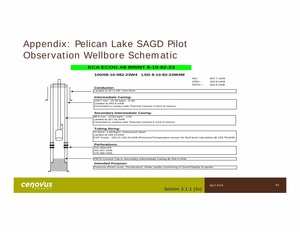
100/08-10-082-23W4 LSD 8-10-82-23W4MKB= 607.7 mKBGRD= 603.9 mKBPBTD = 326.9 mKB
Conductor:
Intermediate Casing:
Secondary Intermediate Casing:
Tubing String:
Perforations:
Intended Purpose:
ECA ECOG A8 BRINT 8-10-82-23
Landed at 20 m KB / 244.5mm
88.9 mm , 13.84 kg/m , J-55Landed at 327.26 mKB Cemented to surface with Thermal Cement 6.1m3 of returns
31.8mm, 1.697kg/m, Galvonized SteelLanded at 193.21mKBESP Pump - 193.21-194.21mKB (Pressure/Temperature sensor for fluid level calculation @ 193.75mKB)
139.7 mm , 25.30 kg/m , K-55Landed at 342.5 mKB Cemented to surface with Thermal Cement 2.0m3 of returns
PBTD Cement Top in Secondary Intermediate Casing @ 326.9 mKB
254-256mKB263-267 mKB276-280 mKB
Pressure (Fluid Level), Temperature, Water quality monitoring of Grand Rapids B aquifer
Appendix: Pelican Lake SAGD PilotObservation Wellbore Schematic
84Section 3.1.1 (5c)
April 2016
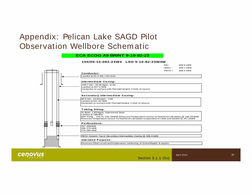
Appendix: Pelican Lake SAGD PilotObservation Wellbore Schematic
85Section 3.1.1 (5c)
100/09-10-082-23W4 LSD 9-10-82-23W4MKB= 608.9 mKBGRD= 605.1 mKBPBTD = 308.4 mKB
Conductor:
Inte rmedia te Casing:
Secondary Inte rmedia te Casing:
T ubing String:
Perfora tions:
Intended Purpose:
ECA ECOG A9 BRINT 9-10-82-23
Landed at 20 m KB / 244.5mm
88.9 mm , 13.84 kg/m , J-55Landed at 321.30 mKB Cemented to surface with Thermal Cement 2.0m3 of returns
31.8mm, 1.697kg/m, Galvonized SteelLanded at 188mKBESP Pump - 193.21-196.78mKB (Pressure/Temperature sensor for f luid level calculation @ 196.32mKB)Pressure/Temperature sensor for f luid level calculation suspended on cable and landed @ 257.0mKB
139.7 mm , 25.30 kg/m , K-55Landed at 337.0 mKB Cemented to surface with Thermal Cement 2.0m3 of returns
PBTD Cement Top in Secondary Intermediate Casing @ 308.4 mKB
257-259mKB266-270 mKB276-280 mKB
Pressure (Fluid Level) andTemperature monitoring of Grand Rapids B aquifer
April 2016
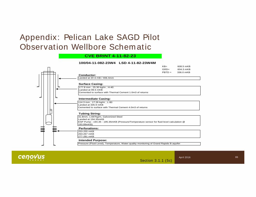
100/04-11-082-23W4 LSD 4-11-82-23W4MKB= 608.5 mKBGRD= 604.3 mKBPBTD = 336.0 mKB
Conductor:
Surface Casing:
Intermediate Casing:
Tubing String:
Perforations:
Intended Purpose:
CVE BRINT 4-11-82-23
Landed at 20 m KB / 406.4mm
114.3 mm , 17.26 kg/m , L-80Landed at 335.9 mKB Cemented to surface with Thermal Cement 4.0m3 of returns
31.8mm, 1.697kg/m, Galvonized SteelLanded at 194.35mKBESP Pump - 194.35 - 195.35mKB (Pressure/Temperature sensor for fluid level calculation @ 193.89mKB)
177.8 mm , 25.30 kg/m , H-40Landed at 99.5 mKB Cemented to surface with Thermal Cement 1.0m3 of returns
253-255 mKB263-267 mKB277-281 mKB
Pressure (Fluid Level), Temperature, Water quality monitoring of Grand Rapids B aquifer
Appendix: Pelican Lake SAGD PilotObservation Wellbore Schematic
86Section 3.1.1 (5c)
April 2016
Appendix: Pelican Lake SAGD PilotObservation Wellbore Schematic
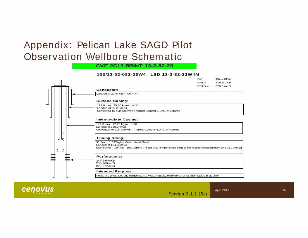
87Section 3.1.1 (5c)
103/13-02-082-23W4 LSD 13-2-82-23W4MKB= 601.2 mKBGRD= 596.9 mKBPBTD = 328.0 mKB
Conductor:
Surface Casing:
Inte rmedia te Casing:
T ubing String:
Perfora tions:
Intended Purpose:
CVE 2C13 BRINT 13-2-82-23
Landed at 20 m KB / 406.4mm
114.3 mm , 17.26 kg/m , L-80Landed at 328.0 mKB Cemented to surface with Thermal Cement 4.0m3 of returns
31.8mm, 1.697kg/m, Galvonized SteelLanded at 194.05mKBESP Pump - 194.05 - 195.05mKB (Pressure/Temperature sensor for f luid level calculation @ 193.77mKB)
177.8 mm , 25.30 kg/m , H-40Landed at 86.25 mKB Cemented to surface with Thermal Cement 1.5m3 of returns
246-248 mKB256-260 mKB273-277 mKB
Pressure (Fluid Level), Temperature, Water quality monitoring of Grand Rapids B aquifer
April 2016
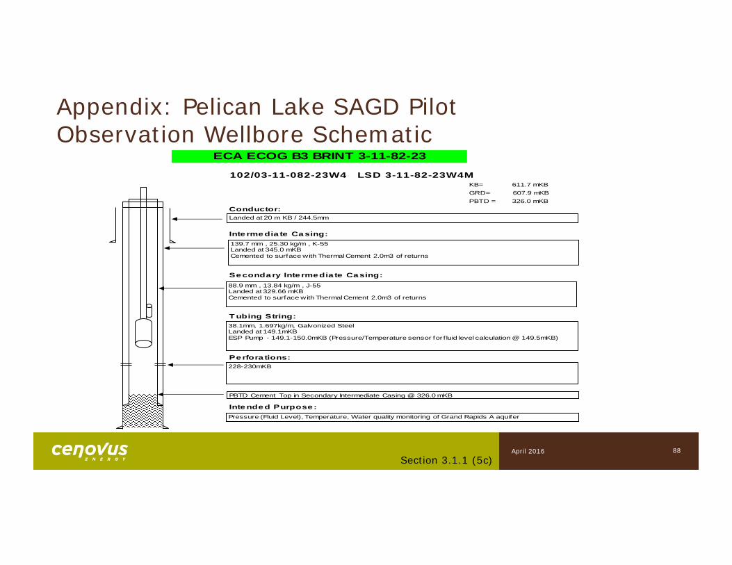
Appendix: Pelican Lake SAGD Pilot Observation Wellbore Schematic
88Section 3.1.1 (5c)
102/03-11-082-23W4 LSD 3-11-82-23W4MKB= 611.7 mKBGRD= 607.9 mKBPBTD = 326.0 mKB
Conductor:
Inte rmedia te Casing:
Secondary Inte rmedia te Casing:
T ubing String:
Perfora tions:
Intended Purpose:
ECA ECOG B3 BRINT 3-11-82-23
Landed at 20 m KB / 244.5mm
88.9 mm , 13.84 kg/m , J-55Landed at 329.66 mKB Cemented to surface with Thermal Cement 2.0m3 of returns
38.1mm, 1.697kg/m, Galvonized SteelLanded at 149.1mKBESP Pump - 149.1-150.0mKB (Pressure/Temperature sensor for f luid level calculation @ 149.5mKB)
139.7 mm , 25.30 kg/m , K-55Landed at 345.0 mKB Cemented to surface with Thermal Cement 2.0m3 of returns
PBTD Cement Top in Secondary Intermediate Casing @ 326.0 mKB
228-230mKB
Pressure (Fluid Level), Temperature, Water quality monitoring of Grand Rapids A aquifer
April 2016
Appendix: Pelican Lake SAGD Pilot Observation Wellbore Schematic
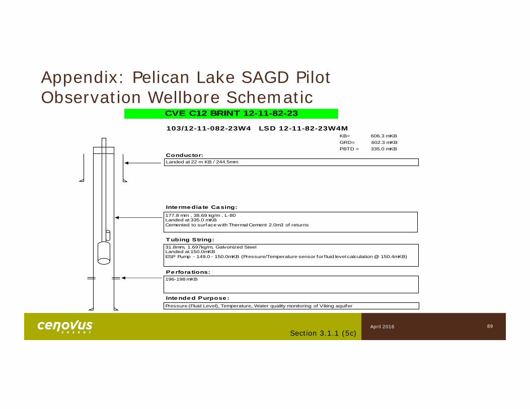
89Section 3.1.1 (5c)
103/12-11-082-23W4 LSD 12-11-82-23W4MKB= 606.3 mKBGRD= 602.3 mKBPBTD = 335.0 mKB
Conductor:
Inte rmedia te Casing:
T ubing String:
Perfora tions:
Intended Purpose:
CVE C12 BRINT 12-11-82-23
Landed at 22 m KB / 244.5mm
177.8 mm , 38.69 kg/m , L-80Landed at 335.0 mKB Cemented to surface with Thermal Cement 2.0m3 of returns
31.8mm, 1.697kg/m, Galvonized SteelLanded at 150.0mKBESP Pump - 149.0 - 150.0mKB (Pressure/Temperature sensor for f luid level calculation @ 150.4mKB)
196-198 mKB
Pressure (Fluid Level), Temperature, Water quality monitoring of Viking aquifer
April 2016
Appendix: Pelican Lake SAGD Pilot Observation Wellbore Schematic
90Section 3.1.1 (5c)
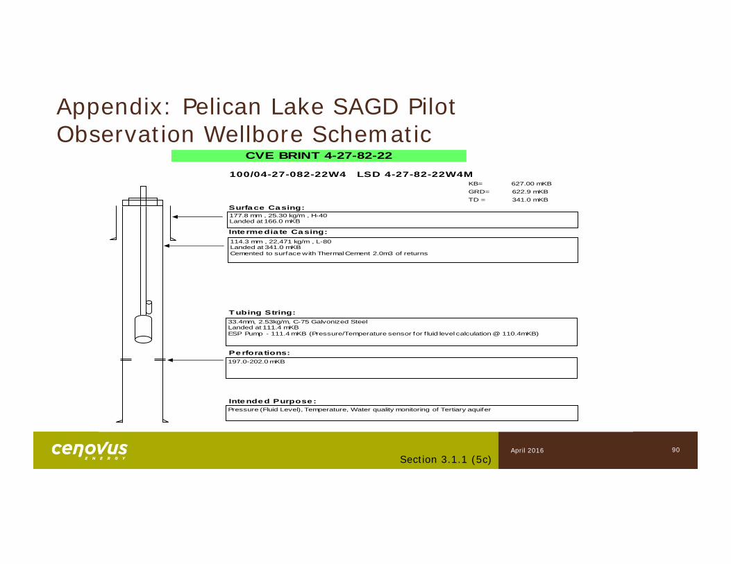
100/04-27-082-22W4 LSD 4-27-82-22W4MKB= 627.00 mKBGRD= 622.9 mKBTD = 341.0 mKB
Surface Casing:
Inte rmedia te Casing:
T ubing String:
Perfora tions:
Intended Purpose:
CVE BRINT 4-27-82-22
33.4mm, 2.53kg/m, C-75 Galvonized SteelLanded at 111.4 mKBESP Pump - 111.4 mKB (Pressure/Temperature sensor for f luid level calculation @ 110.4mKB)
114.3 mm , 22,471 kg/m , L-80Landed at 341.0 mKB Cemented to surface with Thermal Cement 2.0m3 of returns
197.0-202.0 mKB
Pressure (Fluid Level), Temperature, Water quality monitoring of Tertiary aquifer
177.8 mm , 25.30 kg/m , H-40Landed at 166.0 mKB
April 2016
Appendix: Pelican Lake SAGD Pilot Observation Wellbore Schematic
91Section 3.1.1 (5c)
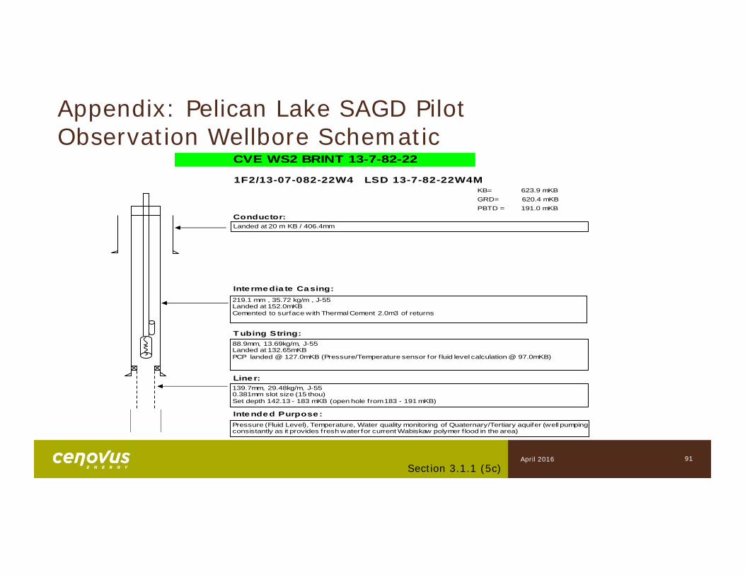
1F2/13-07-082-22W4 LSD 13-7-82-22W4MKB= 623.9 mKBGRD= 620.4 mKBPBTD = 191.0 mKB
Conductor:
Inte rmedia te Casing:
T ubing String:
Line r:
Intended Purpose:
CVE WS2 BRINT 13-7-82-22
Landed at 20 m KB / 406.4mm
219.1 mm , 35.72 kg/m , J-55Landed at 152.0mKB Cemented to surface with Thermal Cement 2.0m3 of returns
88.9mm, 13.69kg/m, J-55Landed at 132.65mKBPCP landed @ 127.0mKB (Pressure/Temperature sensor for f luid level calculation @ 97.0mKB)
139.7mm, 29.48kg/m, J-550.381mm slot size (15 thou)Set depth 142.13 - 183 mKB (open hole from 183 - 191 mKB)
Pressure (Fluid Level), Temperature, Water quality monitoring of Quaternary/Tertiary aquifer (well pumping consistantly as it provides fresh water for current Wabiskaw polymer f lood in the area)
April 2016
Appendix: Pelican Lake SAGD Pilot Observation Wellbore Schematic
92Section 3.1.1 (5c)
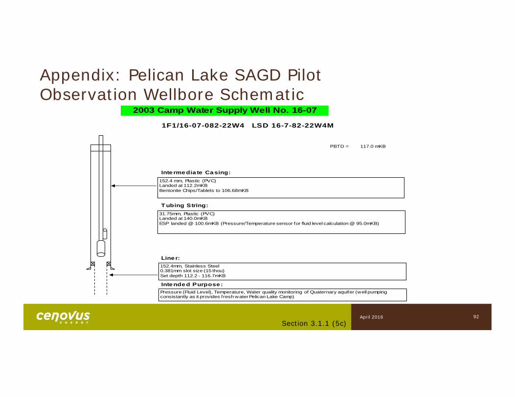
1F1/16-07-082-22W4 LSD 16-7-82-22W4M
PBTD = 117.0 mKB
Inte rmedia te Casing:
T ubing String:
Line r:
Intended Purpose:
2003 Camp Water Supply Well No. 16-07
152.4 mm, Plastic (PVC)Landed at 112.2mKB Bentonite Chips/Tablets to 106.68mKB
31.75mm, Plastic (PVC)Landed at 140.0mKBESP landed @ 100.6mKB (Pressure/Temperature sensor for fluid level calculation @ 95.0mKB)
152.4mm, Stainless Steel0.381mm slot size (15 thou)Set depth 112.2 - 116.7mKB
Pressure (Fluid Level), Temperature, Water quality monitoring of Quaternary aquifer (well pumping consistantly as it provides fresh water Pelican Lake Camp)
April 2016
Appendix: Pelican Lake SAGD Pilot Observation Wellbore Schematic
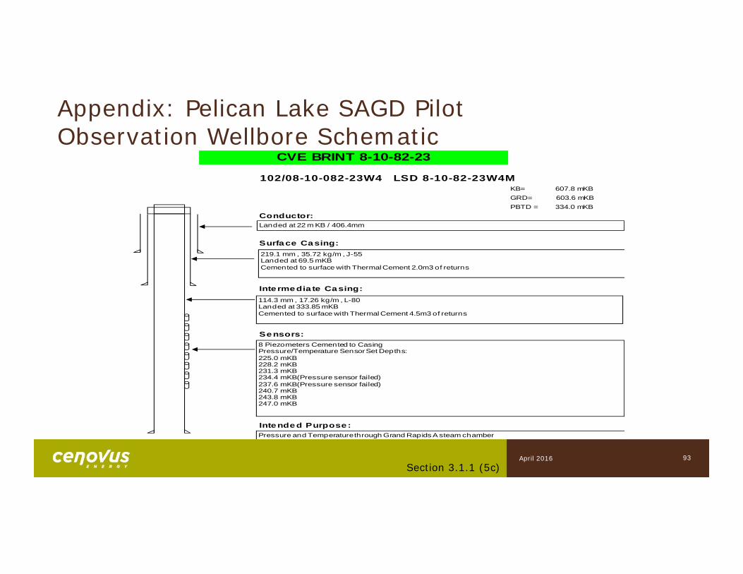
102/08-10-082-23W4 LSD 8-10-82-23W4MKB= 607.8 mKBGRD= 603.6 mKBPBTD = 334.0 mKB
Conductor:
Surface Casing:
Inte rmedia te Casing:
Sensors:
Intended Purpose :
CVE BRINT 8-10-82-23
Landed at 22 m KB / 406.4mm
114.3 mm , 17.26 kg/m , L-80Landed at 333.85 mKB Cemented to surface with Thermal Cement 4.5m3 of returns
8 Piezometers Cemented to CasingPressure/Temperature Sensor Set Depths:225.0 mKB228.2 mKB231.3 mKB234.4 mKB(Pressure sensor failed)237.6 mKB(Pressure sensor failed)240.7 mKB243.8 mKB247.0 mKB
219.1 mm , 35.72 kg/m , J-55Landed at 69.5 mKB Cemented to surface with Thermal Cement 2.0m3 of returns
Pressure and Temperature through Grand Rapids A steam chamber
93Section 3.1.1 (5c)
April 2016
Appendix: Pelican Lake SAGD Pilot Observation Wellbore Schematic
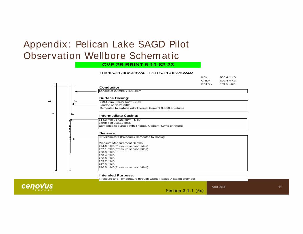
103/05-11-082-23W4 LSD 5-11-82-23W4MKB= 606.4 mKBGRD= 602.4 mKBPBTD = 333.0 mKB
Conductor:
Surface Casing:
Intermediate Casing:
Sensors:
Intended Purpose:
CVE 2B BRINT 5-11-82-23
Landed at 20 mKB / 406.4mm
114.3 mm , 17.26 kg/m , L-80Landed at 332.15 mKB Cemented to surface with Thermal Cement 4.0m3 of returns
8 Piezometers (Pressure) Cemented to Casing
Pressure Measurement Depths:224.0 mKB(Pressure sensor failed)227.1 mKB(Pressure sensor failed)230.3 mKB233.4 mKB236.6 mKB239.7 mKB242.9 mKB246.0 mKB(Pressure sensor failed)
219.1 mm , 35.72 kg/m , J-55Landed at 98.70 mKB Cemented to surface with Thermal Cement 3.0m3 of returns
Pressure and Temperature through Grand Rapids A steam chamber
94Section 3.1.1 (5c)
April 2016
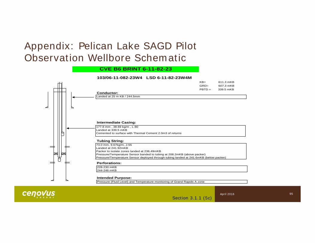
103/06-11-082-23W4 LSD 6-11-82-23W4MKB= 611.3 mKBGRD= 607.3 mKBPBTD = 339.5 mKB
Conductor:
Intermediate Casing:
Tubing String:
Perforations:
Intended Purpose:
CVE B6 BRINT 6-11-82-23
Landed at 25 m KB / 244.5mm
177.8 mm , 38.69 kg/m , L-80Landed at 339.5 mKB Cemented to surface with Thermal Cement 2.0m3 of returns
73.0 mm, 9.67kg/m, J-55Landed at 241.92mKBPacker to isolate zones landed at 236.49mKBPressure/Temperature Sensor banded to tubing at 208.2mKB (above packer)Pressure/Temperature Sensor deployed through tubing landed at 241.6mKB (below packer)
228-230 mKB244-246 mKB
Pressure (Fluid Level) and Temperature monitoring of Grand Rapids A zone
Appendix: Pelican Lake SAGD Pilot Observation Wellbore Schematic
95Section 3.1.1 (5c)
April 2016

102/05-11-082-23W4 LSD 5-11-82-23W4MKB= 606.9 mKBGRD= 603.1 mKBPBTD = 312.7 mKB
Conductor:
Intermediate Casing:
Secondary Intermediate Casing:
Thermocouple String:
Intended Purpose:
ECA ECOG B5 BRINT 5-11-82-23
Landed at 20 mKB / 244.5mm
88.9 mm , 13.84 kg/m , J-55Landed at 317.9 mKB Cemented to surface with Thermal Cement 1.5m3 of returns
WIKA 20 Point Thermocouple Landed 214.0 - 252.0 mKBEach Thermocouple is 2 m apart along the landing depth length
139.7 mm , 25.30 kg/m , K-55Landed at 339.5 mKB Cemented to surface with Thermal Cement 2.0m3 of returns
PBTD Cement Top in Secondary Intermediate Casing @ 312.7 mKB
Temperature monitoring of Grand Rapids A steam chamber
Appendix: Pelican Lake SAGD Pilot Observation Wellbore Schematic
96Section 3.1.1 (5c)
April 2016
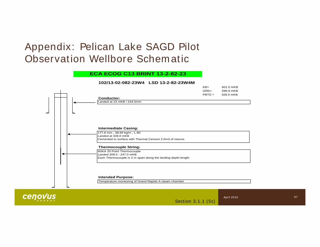
102/13-02-082-23W4 LSD 13-2-82-23W4MKB= 601.0 mKBGRD= 596.9 mKBPBTD = 328.0 mKB
Conductor:
Intermediate Casing:
Thermocouple String:
Intended Purpose:
ECA ECOG C13 BRINT 13-2-82-23
Landed at 23 mKB / 244.5mm
177.8 mm , 38.69 kg/m , L-80Landed at 328.0 mKB Cemented to surface with Thermal Cement 2.0m3 of returns
WIKA 20 Point Thermocouple Landed 209.0 - 247.0 mKBEach Thermocouple is 2 m apart along the landing depth length
Temperature monitoring of Grand Rapids A steam chamber
Appendix: Pelican Lake SAGD Pilot Observation Wellbore Schematic
97Section 3.1.1 (5c)
April 2016
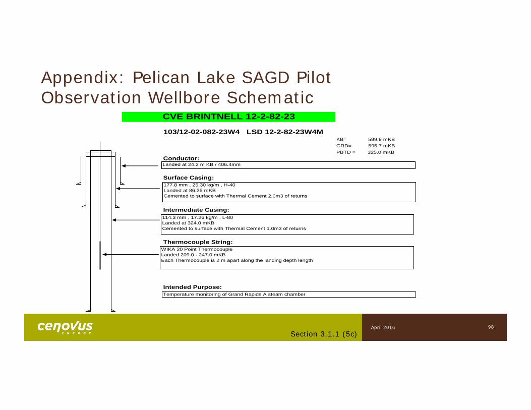
103/12-02-082-23W4 LSD 12-2-82-23W4MKB= 599.9 mKBGRD= 595.7 mKBPBTD = 325.0 mKB
Conductor:
Surface Casing:
Intermediate Casing:
Thermocouple String:
Intended Purpose:
CVE BRINTNELL 12-2-82-23
Landed at 24.2 m KB / 406.4mm
114.3 mm , 17.26 kg/m , L-80Landed at 324.0 mKB Cemented to surface with Thermal Cement 1.0m3 of returns
177.8 mm , 25.30 kg/m , H-40Landed at 86.25 mKB Cemented to surface with Thermal Cement 2.0m3 of returns
WIKA 20 Point Thermocouple Landed 209.0 - 247.0 mKBEach Thermocouple is 2 m apart along the landing depth length
Temperature monitoring of Grand Rapids A steam chamber
Appendix: Pelican Lake SAGD Pilot Observation Wellbore Schematic
98Section 3.1.1 (5c)
April 2016
Appendix: Pelican Lake SAGD Pilot Observation Wellbore Schematic
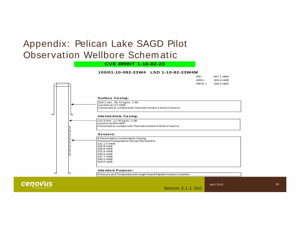
100/01-10-082-23W4 LSD 1-10-82-23W4MKB= 607.1 mKBGRD= 603.0 mKBPBTD = 334.0 mKB
Surface Casing:
Inte rme dia te Ca sing:
Se nsors:
Inte nde d Purpose:
CVE BRINT 1-10-82-23
114.3 mm , 17.26 kg/m , L-80Landed at 334 mKB Cemented to surface with Thermal Cement 3.0m3 of returns
8 Piezometers Cemented to CasingPressure/Temperature Sensor Set Depths:221.1.0 mKB225.8 mKB228.8 mKB231.9 mKB235.0 mKB237.7 mKB240.5 mKB243.0 mKB
219.1 mm , 35.72 kg/m , J-55Landed at 117 mKB Cemented to surface with Thermal Cement 4.0m3 of returns
Pressure and Temperature through Grand Rapids A steam chamber
99Section 3.1.1 (5c)
April 2016
Appendix: Pelican Lake SAGD Pilot Observation Wellbore Schematic
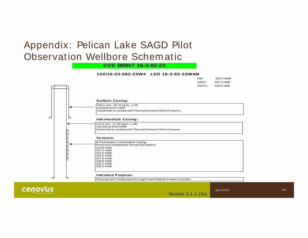
102/16-03-082-23W4 LSD 16-3-82-23W4MKB= 602.0 mKBGRD= 597.9 mKBPBTD = 329.0 mKB
Surface Casing:
Inte rme dia te Ca sing:
Se nsors:
Inte nde d Purpose:
CVE BRINT 16-3-82-23
114.3 mm , 17.26 kg/m , L-80Landed at 329.0 mKB Cemented to surface with Thermal Cement 3.0m3 of returns
8 Piezometers Cemented to CasingPressure/Temperature Sensor Set Depths:214.6 mKB217.2 mKB221.0 mKB223.0 mKB227.0 mKB228.8 mKB232.0 mKB235.2 mKB
219.1 mm , 35.72 kg/m , J-55Landed at 117 mKB Cemented to surface with Thermal Cement 3.0m3 of returns
Pressure and Temperature through Grand Rapids A steam chamber
100Section 3.1.1 (5c)
April 2016

Appendix: Pelican Lake SAGD Pilot Observation Wellbore Schematic
100/09-03-082-23W4 LSD 9-3-82-23W4MKB= 598.5 mKBGRD= 594.4 mKBPBTD = 325.0 mKB
Surface Casing:
Inte rme dia te Ca sing:
Se nsors:
Inte nde d Purpose:
CVE BRINT 9-3-82-23
114.3 mm , 17.26 kg/m , L-80Landed at 325.0 mKB Cemented to surface with Thermal Cement 3.0m3 of returns
8 Piezometers Cemented to CasingPressure/Temperature Sensor Set Depths:211.1 mKB213.6 mKB218.1 mKB221.9 mKB226.3 mKB228.9 mKB232.9 mKB236.1 mKB
219.1 mm , 35.72 kg/m , J-55Landed at 119.0 mKB Cemented to surface with Thermal Cement 3.0m3 of returns
Pressure and Temperature through Grand Rapids A steam chamber
101Section 3.1.1 (5c)
April 2016
Appendix: Pelican Lake SAGD Pilot Observation Wellbore Schematic
102Section 3.1.1 (5c)
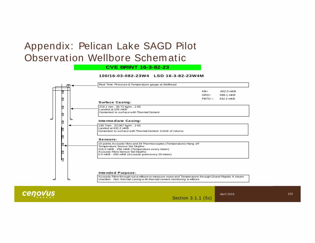
100/16-03-082-23W4 LSD 16-3-82-23W4M
KB= 602.0 mKBGRD= 598.1 mKBPBTD = 432.2 mKB
Surface Casing:
Inte rmedia te Casing:
Sensors:
Intended Purpose:
CVE BRINT 16-3-82-23
139.7mm , 23.067 kg/m , J-55Landed at 432.2 mKB Cemented to surface with Thermal Cement 3.0m3 of returns
10 points Acoustic f ibre and 34 Thermocouples (Temperature) Hang offTemperature Sensor Set Depths:216.0 mKB - 250 mKB (Temperature every meter)Acoustic Fibre Sensor Set Depths:0.0 mKB - 250 mKB (Acoustic point every 25 meter)
219.1 mm , 35.72 kg/m , J-55Landed at 105 mKB Cemented to surface with Thermal Cement
Acoustic Fibre through out w ellbore to measure noise and Temperature through Grand Rapids A steam chamber - Non thermal casing w ith thermal cement monitoring w ellbore
Real Time Pressure & Temperature gauge at Wellhead
April 2016
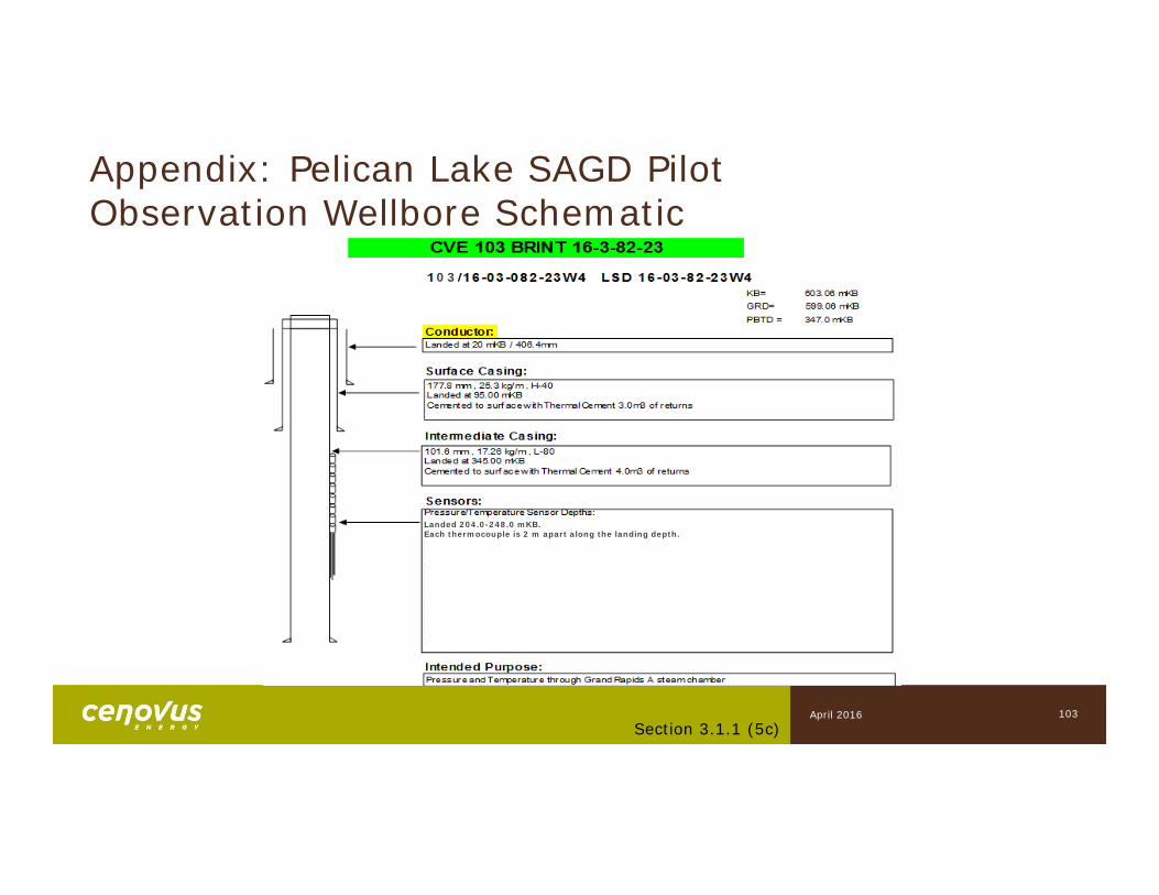
Appendix: Pelican Lake SAGD Pilot Observation Wellbore Schematic
103Section 3.1.1 (5c)
00
03
00
Landed 204.0-248.0 mKB. Each thermocouple is 2 m apart along the landing depth.
April 2016