Embed Size (px)
Citation preview

PRODUCT CATALOGUE2010

2
PEIKKO GROUPPeikko Group, a Finnish family-owned company, is a pioneer in the fastening technology of concrete structures.The company was founded in 1965 by the name of “Teräspeikko”, which translates into “Steel troll”. Peikko’s first product, diagonal tie for sandwich panel, was the first industrial product of that category at the time. The company has ever since remained forward-looking and innovative. It has been able to continuously launch new products together with its customers and successfully implement modern and cost-efficient production technologies.
One of the leading companies in Europe – with a goal to continue to be local Peikko Group operates in more than 20 countries in Europe and has started activities in North-America and Middle-East. With more than 800 employees and with estimated net sales of 120 million EUR in 2008, the company is well-positioned to serve its customers. Peikko Group serves its customers locally via vast network of subsidiaries.
www.peikko.com
SALES, DISTRIBUTION AND PRODUCTION
SALES AND DISTRIBUTION
SALES
Contact information
Peikko Group
Peikko GroupP.O.Box 104Voimakatu 3FIN - 15101 LahtiTel. +358 3 844 511Fax +358 3 733 0152

www.peikko.com
3
CONTENTS
ApprovalsOur products have approvals in various countries including Finland, Germany, Poland, Russia, Great Britain and Sweden. See details in product sections.
Quality and environmentThe results of the work in quality and environment are inspected regularly by external audits carried out by Inspecta Certification, VTT Technical Research Centre, SITAC Swedish Institute for Technical Approval in Construction, Schweißtechnische Lehr- und Versuchsanstalt SLV Hannover and Ministry Of Construction Russia Federal Centre Of Certification / OS Svzapstroisertifikatsiya St. Petersburg.
Technical informationDetailed technical information and limitations for application, requirements for the concrete and correction factors for capacities can be found in product’s technical manual. The technical information is available in our website or as printed manuals on request.
5. REINFORCEMENT PRODUCTS
28
4. TIES
26
3. CORBELS, HANGERS 18
2. BOLTS, COLUMN SHOES
12
1. FASTENING PLATES
4
6. LIFTING SYSTEMS
36
7. BALCONY JOINTS
44
8. EXPANSION JOINTS
46
9. DELTABEAM, PEIKKO FRAME
50

4
1. FASTENING PLATES
KIINNITYSLEVYT
Betoniyhdistyksen käyttöselosteet 230, 242 ja 243Korvaa esitteet 8/02, 11/92 ja 9/91 • väli 1, 9/2007
FASTENING PLATESStandard fastening plates have protective painting 40 µm. Also available in epoxy coating or hot dip galvanized.
SBKL fastening plates
KL fastening plates
JPL fastening plates
PKL fastening plates
P2KL fastening plates
P3KL fastening plates
Plate thickness 8 - 15 mm. Headed studs. For lighter loads. Especiallly for walls and thin structures.
Plate thickness 8 - 15 mm. Straight ribbed bars as anchors. Welded on surface. Especially suits well on dynamic anchoring
Long fastening plate. Standard lenght 2 m. Plate thickness 12 mm and headed studs welded on surface.
Long fastening plate. Standard lenght 2 m. Plate thickness 15 or 20 mm and headed studs welded on hole.
Long fastening plate. Plate thickness 25 mm and headed studs welded on hole.
Plate thickness 25 or 30 mm. Ribbed bars with headed studs. Standard fastening plate for demanding fi xings.
Collection of fastening items for standard elements. Mainly for prefabricators
Corner protector. Anchors welded on surface. 25 mm chamfer on corner. Delivered painted A40 μm, hot dip galvanized or stainless.
KS corner protector
TR fastening items
Corner protector. Standard lenght 6m. Anchors are welded on surface. Is being used in columns, fl oors and walls. Delivered painted A40μm, hot dip galvanized or stainless.
Fastening angle bar for opening or corner. Anchors as in UKT. Standard lenght 6 m.
To edge of openings in which the cover plate is installed. Standard lenght 6 m.
Standard lenght 6m. Headed for anchors.Standard angles 50, 80 and 100 mm.
UKT fastening angle bar
SKT fastening angle bar
KKT fastening angle barSupport for chequered plate

5
www.peikko.com
Fast
enin
g p
late
s
AxDxt H d a Ø NRd VRd MRdD MRdA Trd JPL
[mm] [kN] [kNm] [kg]
JPL 150x150 150x150x25 220 90 90 16 177 61,0 15,1 15,1 4,8 5,9
JPL 150x200 150x200x25 220 120 100 20 295 96,7 31,4 23,6 8,9 8,3
JPL 150x250 150x250x25 220 190 100 20 316 101,0 49,7 23,6 12,5 9,8
JPL 200x200 200x200x25 220 120 120 20 314 100,4 31,4 31,4 10,0 10,3
JPL 200x250 200x250x25 220 190 120 20 339 103,0 49,7 31,4 13,3 12,2
JPL 250x250 250x250x25 220 190 190 20 369 107,0 49,7 49,7 15,9 14,7
JPL 200x300 200x300x25 280 200 120 25 533 161,0 81,8 49,1 21,6 16,6
JPL 300x300 300x300x25 280 200 200 25 584 168,0 81,8 81,8 26,2 22,5
JPL 400x400 400x400x30 280 300 300 25 646 173,0 123,0 123,0 39,3 44,0
JPL 500x500 500x500x30 280 400 400 25 682 176,0 164,0 164,0 52,3 63,7
JPL 600x600 600x600x30 280 500 500 25 705 178,0 205,0 205,0 65,4 89,6
plate anchor
JPL S355J0 A500HW
JPLR 1.4301 A500HW
JPLRr 1.4301 hot-rolled stainless rebar*
JPLH 1.4401 A500HW
*= strenght equal to A500HW
NRd VRd MRdD MRdA TrdTrdT
[kN] [kNm]
177 61,0 15,1 15,1 4,8
295 96,7 31,4 23,6 8,9
316 101,0 49,7 23,6 12,5
314 100,4 31,4 31,4 10,0
339 103,0 49,7 31,4 13,3
369 107,0 49,7 49,7 15,9
533 161,0 81,8 49,1 21,6
584 168,0 81,8 81,8 26,2
646 173,0 123,0 123,0 39,3
682 176,0 164,0 164,0 52,3
705 178,0 205,0 205,0 65,4
Ht
ø
D
A
d
a
JPLFor fi xings where great capacities are needed.
JPL is painted A40 μm. We also manufacture completely stainless and acid-proof JPL fastening plates.
JPL fastening plates
Materials of JPLAPPROVALS:ETA 04/0056,BY243 Finland,3403/89 Sweden,AT-15-5256/2002 Poland,POCC FI.C∏19.H00289 Russia.

6
AxDxt H d a Ø NRd VRd MRdD MRdA TRd SBKL
[mm] [kN] [kNm] [kg]
SBKL 50x100 50x100x8 68 60 - 12 7,7 9,8 0,38 0,28 0,49 0,5
SBKL 100x100 100x100x8 68 60 60 12 13,7 19,3 0,68 0,68 1,38 0,9
SBKL 100x150 100x150x10 70 90 60 12 18,4 19,3 1,20 0,91 1,76 1,5
SBKL 150x150 150x150x12 162 90 90 12 39,6 22,6 2,57 2,57 2,10 2,7
SBKL 100x200 100x200x12 162 120 60 12 37,2 19,3 2,96 1,86 2,15 2,5
SBKL 200x200 200x200x12 162 120 120 16 82,8 43,5 6,62 6,62 4,92 4,9
SBKL 250x250 250x250x15 165 170 170 16 91,7 45,0 8,70 8,70 6,0 8,6
SBKL 100x300 100x300x15 165 180 60 16 72,3 34,8 7,94 3,61 5,50 4,7
SBKL 200x300 200x300x15 165 180 120 16 90,3 43,5 9,94 7,22 6,28 8,2
SBKL 300x300 300x300x15 165 180 180 16 98,5 47,5 10,80 10,80 7,38 11,9
AxDxt H d a Ø NRd VRd MRdD MRdA TRd KL
[mm] [kN] [kNm] [kg]
KL 50x100 50x100x8 218 60 - 12 7,7 9,8 0,38 0,28 0,49 0,7
KL 100x100 100x100x8 218 60 60 12 13,7 19,3 0,68 0,68 1,38 1,4
KL 100x150 100x150x10 220 90 60 12 18,4 19,3 1,20 0,91 1,76 2,0
KL 150x150 150x150x12 222 90 90 16 39,6 22,6 2,57 2,57 2,10 3,6
KL 100x200 100x200x12 222 120 60 16 37,2 19,3 2,96 1,86 2,15 3,3
KL 200x200 200x200x12 312 120 120 20 82,8 43,5 6,62 6,62 4,92 6,9
KL 100x300 100x300x15 315 180 60 20 72,3 34,8 7,94 3,61 5,50 6,7
KL 200x300 200x300x15 315 180 120 20 90,3 43,5 9,94 7,22 6,28 10,3
KL 300x300 300x300x15 315 180 180 20 98,5 47,5 10,80 10,80 7,38 13,9
plate anchors
KL S355J0 A500HW
KLR 1.4301 A500HW
KLH 1.4401 A500HW
plate anchors
SBKL S355J0 S235J2+N/S355J2+N
SBKLR 1.4301 S235J2+N/S355J2+N
SBKLRr 1.4301 1.4301
SBKLH 1.4401 S235J2+N/S355J2+N
NRd VRd MRdD MRdA TRd
[kN] [kNm]
7,7 9,8 0,38 0,28 0,49
13,7 19,3 0,68 0,68 1,38
18,4 19,3 1,20 0,91 1,76
39,6 22,6 2,57 2,57 2,10
37,2 19,3 2,96 1,86 2,15
82,8 43,5 6,62 6,62 4,92
91,7 45,0 8,70 8,70 6,0
72,3 34,8 7,94 3,61 5,50
90,3 43,5 9,94 7,22 6,28
98,5 47,5 10,80 10,80 7,38
NRd VRd MRdD MRdA TRd
[kN] [kNm]
7,7 9,8 0,38 0,28 0,49
13,7 19,3 0,68 0,68 1,38
18,4 19,3 1,20 0,91 1,76
39,6 22,6 2,57 2,57 2,10
37,2 19,3 2,96 1,86 2,15
82,8 43,5 6,62 6,62 4,92
72,3 34,8 7,94 3,61 5,50
90,3 43,5 9,94 7,22 6,28
98,5 47,5 10,80 10,80 7,38
t Hø
D
Aa
d
H
t
ø
A
D
a
d
SBKL fastening plates
KL fastening plates
SBKL is painted A40μm. SBKL 50/100 and SBKLR 50/100 are packed 40 pcs / box.
KL is painted A40μm. KL 50/100 and KLR 50/100 are packed 30 pcs / box. KL 100/100 and KLR 100/100 are packed 20 pcs / box. We also manufacture completely stainless or acid-proof KL fastening plates.
Materials of KL
Materials of SBKLAPPROVALS:ETA 04/0056,BY266 Finland,3403/89 Sweden,AT-15-5256/2002 Poland,POCC FI.C∏19.H00289 Russia
APPROVALS:BY266 Finland,3403/89 Sweden,AT-15-5256/2002 Poland,POCC FI.C∏19.H00289 Russia

7
www.peikko.com
Fast
enin
g p
late
s
A H a Ø t c/c NRd VRd1 VRd2 weight
[mm] [kN] [~kg/m]
PKL 100 100 70 50 12 10 150 15,2 14,4 13,4 9
PKL 150 150 70 90 12 10 150 22,7 14,4 13,8 13
PKL 200 200 70 100 12 10 150 24,4 14,4 13,9 17
Prices are for the lenght L=2000 mm
A H a Ø t c/c NRd VRd1 VRd2 weight
[mm] [kN] [~kg/m]
P2KL 100 100 115 50 16 15 200 35,6 24,9 24,8 14
P2KL 150 150 115 90 16 15 200 44,4 25,0 24,8 20
P2KL 200 200 115 100 16 15 200 45,7 25,0 24,8 26
P2KL 300 300 115 200 16 15 200 53,3 25,4 24,8 38
P2KL 400 400 115 200 16 20 200 53,3 25,4 24,8 66
Prices are for the lenght L=2000 mm
A H a Ø t c/c NRd VRd1 VRd2 weight
[mm] [kN] [~kg/m]
P3KL 300 300 220 200 20 25 200 143,5 57,6 56,8 68
P3KL 400 400 220 300 20 25 200 143,5 58,3 56,8 88
P3KL 500 500 220 400 20 25 200 143,5 59,1 56,8 108
P3KL 600 600 220 500 20 25 200 143,5 59,7 56,8 128
plate anchors
PKL, P2KL, P3KL S355J0 S235J2+N/S355J2+N
PKLR, P2KLR, P3KLR 1.4301 S235J2+N/S355J2+N
PKLH, P2KLH, P3KLH 1.4401 S235J2+N/S355J2+N
APPROVALS:BY230 Finland,3403/89 Sweden,AT-15-5256/2002 Poland,POCC FI.C∏19.H00289 Russia.
NRd VRd1 VRd2
[kN]
35,6 24,9 24,8
44,4 25,0 24,8
45,7 25,0 24,8
53,3 25,4 24,8
53,3 25,4 24,8
NRd VRd1 VRd2
[kN]
15,2 14,4 13,4
22,7 14,4 13,8
24,4 14,4 13,9
NRd VRd1 VRd2
[kN]
143,5 57,6 56,8
143,5 58,3 56,8
143,5 59,1 56,8
143,5 59,7 56,8
at Hø
A
c/c
a
t Hø
A
c/c
t H
a
ø
A
c/c
PKL fastening plates
P2KL fastening plates
P3KL fastening plates
Materials of PKL, P2KL, P3KL
Long fastening plates (PKL, P2KL ja P3KL) capacities are per one row of anchors.

8
H D t Ø VRd weight
[mm] [kN] [kg]
TR 15 570 455 8 10 34,6 2,5
TR 16 675 480 10 12 50,4 3,9
D A angle Ø N1Rd N2Rd VRd MRd weight
[mm] [kN] [kNm] [kg]
TR 23 270 100 60x60x6 6 (7) 13,8 3,6 6,0 0,53 0,8
TR 24 350 100 80x80x8 8 (9) 24,8 6,4 10,7 1,26 1,5
H D A angle Ø NRd V1Rd V2Rd weight
[mm] [kN] [kg]
TR 25 350 315 150 80x80x8 8 83,7 16,0 7,2 2,0
TR 26 450 415 150 100x100x10 10 117,5 28,5 14,1 3,2
H D A angle Ø NRd VRd MRd weight
[mm] [kN] [kNm] [kg]
TR 36 200 210 80 60x60x6 6 (7) 8,7 6,0 0,65 0,9
TR 37 250 270 100 80x80x8 8 (9) 18,0 10,7 1,80 1,6
angle anchors std. packaging
TR 23/ TR 24 S235JR A500HW 20 pcs / box
TRR 23/ TRR 24 1.4301 A500HW 20 pcs / box
TRRr 23/ TRRr 24 1.4301 B600KX 20 pcs / box
plate anchors std. packaging
TR 15 S355J0 A500HW 150 kpl / FIN-pallet
TR 16 S355J0 A500HW 100 kpl / FIN-pallet
angle anchors std. packaging
TR 25/ TR 26 S235JR A500HW 150 kpl / FIN-pallet
angle anchors std. packaging
TR 36/ TR 37 S235JR A500HW 30 / 20 pcs / box
TRR 36/ TRR 37 1.4301 A500HW 30 / 20 pcs / box
TRRr 36/ TRRr 37 1.4301 B600KX 30 / 20 pcs / box
VRd
[kN]
34,6
50,4
N1Rd N2Rd VRd MRd
[kN] [kNm]
13,8 3,6 6,0 0,53
24,8 6,4 10,7 1,26
NRd V1Rd V2Rd
[kN]
83,7 16,0 7,2
117,5 28,5 14,1
NRd VRd MRd
[kN] [kNm]
8,7 6,0 0,65
18,0 10,7 1,80
D
øH
t
D
A
ø
D
øH
A
øH
H
D
A
TR 15 and TR 16 support for square panels
TR 23 and TR 24 anchors for edges
TR 25 and TR 26 counter supports for square panels
TR 36 and TR 37 angle bars
APPROVALS:BY247 Finland,POCC FI.C∏19.H00289 Russia
FASTENING ITEMSFastening items are steel plates or angle bars, which transfers the loads with the help of the anchors to the concrete.
TR 15 and TR 25

9
www.peikko.com
Fast
enin
g p
late
s
H D A t Ø NRd VRd MRd weight
[mm] [kN] [kNm] [kg]
TR 38 45 560 100 10 8 (9) 14,4 13,7 0,89 1,5
plate anchors std. packaging
TR 38 S355J0 A500HW 100 pcs / FIN-pallet
TRR 38 1.4301 A500HW 150 pcs / pallet
TRRr 38 1.4301 B600KX 100 pcs / FIN-pallet
H D A t Ø NRd VRd weight
[mm] [kN] [kg]
TR 39 40 309 150 6 8 16,7 10,7 0,8
plate anchors std. packaging
TR 39 S355J0 A500HW 20 pcs / box
H D A t Ø NRd V1Rd V2Rd M1Rd M2Rd weight
[mm] [kN] [kNm] [kg]
TR 43 45 340 150 8 8 (9) 5,0 29,0 10,7 0,23 0,56 1,4
TR 45 45 340 100 8 8 (9) 4,3 23,0 10,7 0,18 0,41 1,4
plate anchors fl at steel std. packaging
TR 43/ TR 45 S355J0 A500HW S235JR 20 pcs / box
TRRr 43/ TRRr 45 1.4301 B600KX 1.4301 20 pcs / box
H D A t Ø NRd VRd weight
[mm] [kN] [kg]
TR 44 530 350 100 8 10 44,9 16,8 1,2
plate anchors std. packaging
TR 44 S355J0 A500HW 150 pcs / FIN-pallet
TRR 44 1.4301 A500HW 150 pcs / FIN-pallet
TRRr 44 1.4301 B600KX 150 pcs / FIN-pallet
NRd VRd MRd
[kN] [kNm]
14,4 13,7 0,89
NRd VRd
[kN]
16,7 10,7
NRd V1Rd V2Rd M1Rd M2Rd
[kN] [kNm]
5,0 29,0 10,7 0,23 0,56
4,3 23,0 10,7 0,18 0,41
NRd VRd
[kN]
44,9 16,8
A
A
DH
t
ø
H
49
t
D
ø
A
H
D
A
ø
A
D
t
H
TR 38 anchor for slab
TR 39 anchor for double T-slab
TR 43 and TR 45 anchors for edges
TR 44 fastening part for double T-slab

10
angle Ø c/c weight
[mm] [~kg/m]
SKT 50 50x50x5 6 300 4,2
SKT 70 70x70x7 6 300 7,8
UKT 40 40x40x4 6 300 2,8
UKT 50 50x50x5 6 300 4,2
UKT 60 60x60x6 6 300 5,9
UKT 70 70x70x7 6 300 7,8
UKT 80 80x80x8 6 300 10,2
UKT 100x50 100x50x8 6 300 9,6
UKT 100 100x100x10 6 300 16,0
Lenghts are L=6000 mm
angle anchors
SKT / UKT S235JR A500HW
SKTRr / UKTRr 1.4301 B600KX
SKTHr / UKTHr 1.4401 B600KX
L AxDxt Ø c/c weight
[mm] [~kg/m]
Corner protector KS 1800 60x60x4 8 400 4,0
angle anchors
KS S235JR A500HW
KSRr 1.4301 B600KX
KSHr 1.4401 B600KX
L Ø c/c weight
[mm] [~kg/m]
Support for chequered plate 6000 6 300 5,0
angle anchors
Support for chequered plate S235JR A500HW
c/cø
SKT
c/cø
UKT
40
21
Ø8
110
c/c
øc/c
2030
7
50
SKT and UKT fastening angle bars
KS corner protector
Support for chequered plate
KS corner protector; to protect chamfered corners of columns.
SKT –anchor for inner corners; to bear for example channels.
UKT –anchor for outer corners; to for example threshold for carage, corners of stairs, cor-ner protection and expansion joints..
Non stainless models available as painted or hot dip galvanized.
Items available also as hot dip galvanized.

11
www.peikko.com
Fast
enin
g p
late
s
K40-1 K30-2 weight
VRd NRd1 NRd2 TRd MRd VRd NRd1 NRd2 TRd MRd
[kN] [kNm] [kN] [kNm] [kg]
KKT 50x100 99,2 55,0 20,0 10,4 6,2 78,0 41,0 14,9 7,7 4,6 3,6
angle bar anchors
KKT 50x100 S235JR A500HW
K40-1 K30-2 weight
VRd TRd VRd TRd
[kN] [kNm] [kN] [kNm] [kg]
KKJ 50x100 99,2 10,4 78,0 7,7 4,2
angle bar fl at steel anchors
KKJ 50x100 S235JR S235JR A500HW
angle Ø c/c H NRdd VRdd weight
[mm] [kN] [~kg/m]
KKT 50 50x50x5 12 250 160 14,6 16,3 5,3
KKT 60 60x60x6 12 250 160 14,6 16,3 6,3
KKT 70 70x70x7 12 250 160 14,6 16,3 8,4
KKT 80 80x80x8 12 250 160 14,6 16,3 11,2
KKT 100 100x100x10 16 200 150 26,0 28,7 18,0
Prices are L=6000 mm
angle bar anchors
KKT S235JR S235J2+N / S355J2+N
KKTR 1.4301 S235J2+N / S355J2+N
KKTH 1.4401 S235J2+N / S355J2+N
NRdd VRdd
[kN]
14,6 16,3
14,6 16,3
14,6 16,3
14,6 16,3
26,0 28,7
K40-1 K30-2
VRd NRd1 NRd2 TRd MRd VRd NRd1 NRd2 TRd MRd
[kN] [kNm] [kN] [kNm]
99,2 55,0 20,0 10,4 6,2 78,0 41,0 14,9 7,7 4,6
K40-1 K30-2
VRd TRd VRd TRd
[kN] [kNm] [kN] [kNm]
99,2 10,4 78,0 7,7
ø
30Hc/c
KKT 50 - KKT 80
H
ø
30c/c
KKT 100
50
100
Ø16
333170
125
50 80
125
Ø16
334
170
100
125
KKT 50/100 angle bar for upper corner of beam
KKJ 50/100 “fl exible” angle bar for upper corner of beam
APPROVALS:BY248 Finland,POCC FI.C∏19.H00289 Russia
KKT fastening angle bar
APPROVALS:BY230 Finland,AT-15-5256/2002 Poland,POCC FI.C∏19.H00289 Russia
KKT; for load bearing corner fastening
APPROVALS:BY248 Finland,POCC FI.C∏19.H00289 Russia
Non stainless models available as painted or hot dip galvanized.

12
HPM JA PPMPULTIT
Betoniyhdistyksen käyttöseloste nro 244Korvaa esitteen 8/2002 • Väli 2, 9/2007
PILARIKENGÄTHPKM, PPKM, PEC, PKKM
Betoniyhdistyksen käyttöselosteet nro 219, 206, 224Korvaa esitteen 11/2006 • Väli 2, 9/2007
2. BOLTS, COLUMN SHOES
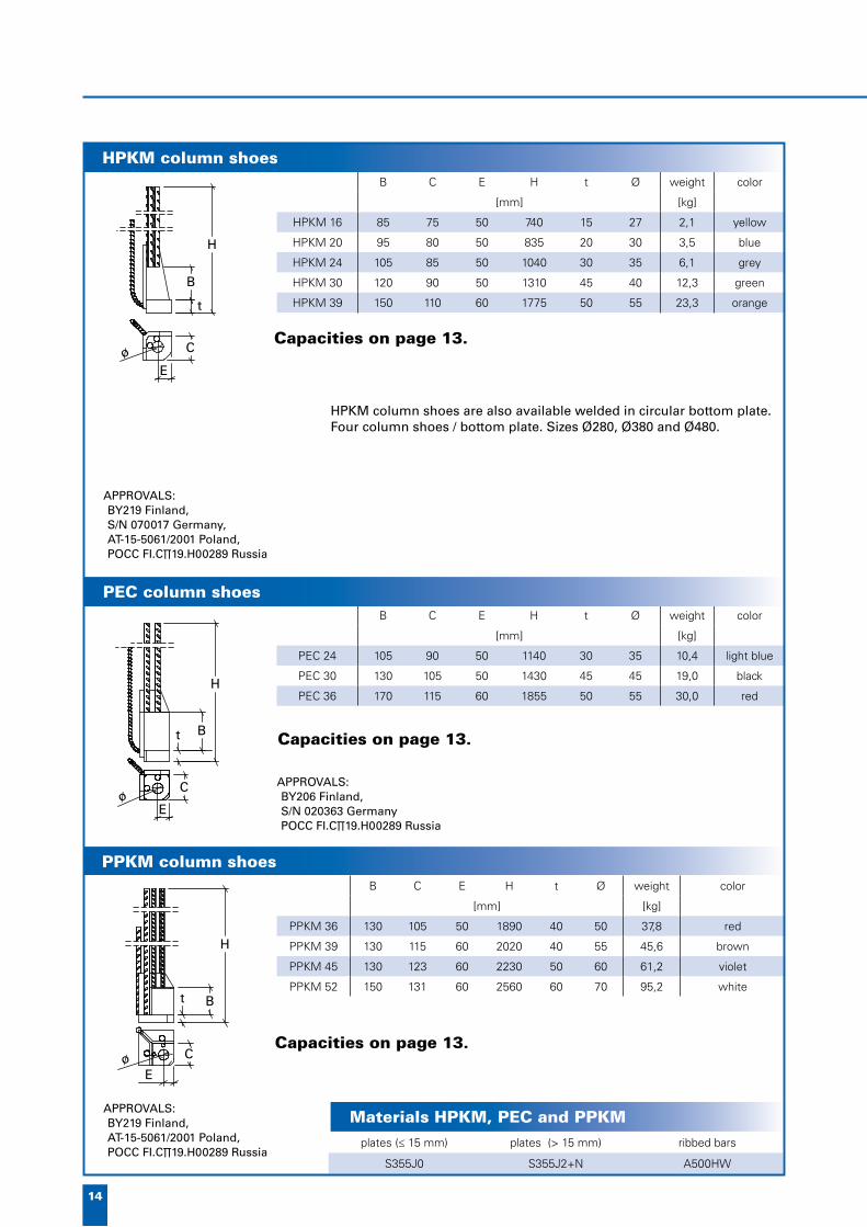
HPKM column shoes
PPKM column shoes
COLUMN-BOLT JOINTColumn shoes are fastening items which allow moment stiff extensions and connections between prefabricated columns and for example foundations.
All forces on the column are transferred with column shoes and bolts to the bearing structure, for example to the foundation.
Component column is possible to set at the correct height level and vertical position. The joint between column base and structure below should be grout as soon as possible after instal-lation. After that the connection parts and grouting will work as reinforced concrete structure. The above structures may not be installed before the con-nection joints are cast and hardened.
With the help of HPKM column shoes, moment stiff joints can be made.The light weight of the HPKM makes the handling and installation easy and fast.
With the help of PPKM column shoes, very high capacity for the moment stiff column joints can be made.
PEC column shoes
Easy handling, lightness and high capacities are combined in PEC column shoes.
PPM anchor bolts
PPM/P bolts are used as overlapping bolts in columns and as basic bolts. The main reinforcement of the basic bolt is attached to reinforcement of the column with an overlap.
PPM/L bolts are used as a basic bolts and anchor bolts in founda-tions.
HPM anchor bolts
HPM/P ribbed bar bolts are used as overlapping bolts in pre-cast columns and as foundation bolts.
HPM/L are also used as anchor bolts in foundations, and they are suitable for bolt joints at the top of concrete beams or on sides of columns.
The number of column shoes in the column depends on the dimensions of the column, forces on the column, concrete grade and type of column shoe used. Usually four col-umn shoes are enough to create a moment stiff connection.
The capacities of the joints are defi ned by the bolt being used.

13
www.peikko.com
Bo
lts,
co
lum
n s
ho
es
Column shoe and bolt usedETA K40-1 K40-2
NRd [kN]
HPKM 16 HPM 16 61.7 71.3 65.4
HPKM 20 HPM 20 96.3 111.3 102.0
HPKM 24 HPM 24 138.7 160.4 147.0
HPKM 30 HPM 30 220.4 255.0 233.7
HPKM 39 HPM 39 383.4 443.6 406.6
PPKM 36 PPM 36 435.7 519.9 476.6
PPKM 39 PPM 39 520.5 621.1 569.3
PPKM 45 PPM 45 696.5 831.1 761.8
PPKM 52 PPM 52 937.6 1118.7 1025.5
PEC 24 PPM 22 161.6 212.1 194.4
PEC 30 PPM 27 244.8 321.3 294.5
PEC 36 PPM 36 435.7 519.9 476.6
PKKM 36 PPM 36 435.7 519.9 476.6
PKKM 45 PPM 45 696.5 831.1 761.8
PKKM 52 PPM 52 937.6 1118.7 1025.5
The given capacities are according to EC2 and Finnish regulations.
CORNER CASTING BOX MIDDLE CASTING BOX
HPKM 16
CBOX
HPKM 20
CBOX
HPKM 24
CBOX
HPKM 30
CBOX
HPKM 39
CBOX
PEC 30
CBOX
PEC 36
CBOX
HPKM 16
MBOX
HPKM 20
MBOX
HPKM 24
MBOX
HPKM 30
MBOX
HPKM 39
MBOX
PEC 30
MBOX
PEC 36
MBOX
yellow blue grey green orange black red yellow blue grey green orange black red
thread M16 M20 M22 M24 M27 M30 M36 M39 M45 M52
wrench 24 30 34 36 41 46 55 60 70 80
2x50x100 3x50x100 5x50x100 8x50x100 10x50x100 15x50x100
2x100x100 3x100x100 5x100x100 8x100x100 10x100x100 15x100x100
ETA K40-1 K40-2
NRd [kN]
61.7 71.3 65.4
96.3 111.3 102.0
138.7 160.4 147.0
220.4 255.0 233.7
383.4 443.6 406.6
435.7 519.9 476.6
520.5 621.1 569.3
696.5 831.1 761.8
937.6 1118.7 1025.5
161.6 212.1 194.4
244.8 321.3 294.5
435.7 519.9 476.6
435.7 519.9 476.6
696.5 831.1 761.8
937.6 1118.7 1025.5
Capacities of column connection
Wrench size
Casting box
Installation parts
Standard installation parts direct from storage.
14
B C E H t Ø weight color
[mm] [kg]
HPKM 16 85 75 50 740 15 27 2,1 yellow
HPKM 20 95 80 50 835 20 30 3,5 blue
HPKM 24 105 85 50 1040 30 35 6,1 grey
HPKM 30 120 90 50 1310 45 40 12,3 green
HPKM 39 150 110 60 1775 50 55 23,3 orange
B C E H t Ø weight color
[mm] [kg]
PPKM 36 130 105 50 1890 40 50 37,8 red
PPKM 39 130 115 60 2020 40 55 45,6 brown
PPKM 45 130 123 60 2230 50 60 61,2 violet
PPKM 52 150 131 60 2560 60 70 95,2 white
plates (≤ 15 mm) plates (> 15 mm) ribbed bars
S355J0 S355J2+N A500HW
B C E H t Ø weight color
[mm] [kg]
PEC 24 105 90 50 1140 30 35 10,4 light blue
PEC 30 130 105 50 1430 45 45 19,0 black
PEC 36 170 115 60 1855 50 55 30,0 red
t
H
B
CøE
Bt
H
Eø C
t B
H
C
Eø
HPKM column shoes
PPKM column shoes
APPROVALS:BY219 Finland,AT-15-5061/2001 Poland,POCC FI.C∏19.H00289 Russia
HPKM column shoes are also available welded in circular bottom plate. Four column shoes / bottom plate. Sizes Ø280, Ø380 and Ø480.
Materials HPKM, PEC and PPKM
APPROVALS:BY206 Finland, S/N 020363 GermanyPOCC FI.C∏19.H00289 Russia
Capacities on page 13.
Capacities on page 13.
Capacities on page 13.
APPROVALS:BY219 Finland,S/N 070017 Germany,AT-15-5061/2001 Poland,POCC FI.C∏19.H00289 Russia
PEC column shoes

15
www.peikko.com
Bo
lts,
co
lum
n s
ho
es
L A Ø washer NRd weight
[mm] [kN] [kg]
HPM 16L 280 140 16 ø 38-6 61,7 0,9
HPM 16P 810 140 16 ø 38-6 61,7 1,7
HPM 20L 350 140 20 ø 46-6 96,3 1,4
HPM 20P 1000 140 20 ø 46-6 96,3 2,9
HPM 24L 430 170 25 ø 56-6 138,7 2,1
HPM 24P 1160 170 25 ø 56-6 138,7 4,9
HPM 30L 500 190 32 ø 65-8 220,4 4,4
HPM 30P 1420 190 32 ø 65-8 220,4 9,4
HPM 39L 700 200 40 ø 90-10 383,4 9,0
HPM 39P 2000 200 40 ø 90-10 383,4 21,1
L A Ø washer NRd weight
[mm] [kN] [kg]
PPM 22L 510 160 2ø20 ø 56-6 161,6 3,2
PPM 22P 1190 160 2ø20 ø 56-6 161,6 6,0
PPM 27L 650 170 2ø25 ø 65-8 244,8 5,7
PPM 27P 1415 170 2ø25 ø 65-8 244,8 11,5
PPM 30L 670 190 2ø25 ø 65-8 299,2 6,2
PPM 30P 1705 190 2ø25 ø 65-8 299,2 14,1
PPM 36L 740 190 4ø20 ø 80-8 435,7 9,4
PPM 36P 1450 190 4ø20 ø 80-8 435,7 15,7
PPM 39L 880 190 3ø25 ø 90-10 520,5 12,6
PPM 39P 1815 190 3ø25 ø 90-10 520,5 23,5
PPM 45L 980 220 4ø25 ø 100-10 696,5 18,2
PPM 45P 1825 220 4ø25 ø 100-10 696,5 31,1
PPM 52L 1140 250 4ø32 ø 100-12 937,6 32,3
PPM 52P 1930 250 4ø32 ø 100-12 937,6 50,0
PPM 60L 1330 310 4ø32 ø 115-15 1259,7 41,9
PPM 60P 2490 310 4ø32 ø 115-15 1259,7 70,9
ribbed bars A500HW / BSt500S
washers S355J0
nuts property class 8
thread bar imacro M
ribbed bars A500HW
washers S355J0
nuts property class 8
NRd
[kN]
61,7
61,7
96,3
96,3
138,7
138,7
220,4
220,4
383,4
383,4
NRd
[kN]
161,6
161,6
244,8
244,8
299,2
299,2
435,7
435,7
520,5
520,5
696,5
696,5
937,6
937,6
1259,7
1259,7
L
A
ø
HPM L
A
L
ø
HPM P
Lø
A
PPM L
Lø
A
PPM P
APPROVALS:HPM L:ETA-02/0006,BY244 Finland,AT-15-5060/2001 Poland,POCC FI.C∏19.H00289 Russia
HPM P:BY244 Finland,AT-15-5060/2001 Poland,POCC FI.C∏19.H00289 Russia
APPROVALS:PPM L:BY244 Finland,Z-21.5-1706 Germany,AT-15-5060/2001 Poland,POCC FI.C∏19.H00289 Russia
PPM P:BY244 Finland,AT-15-5060/2001 Poland,POCC FI.C∏19.H00289 Russia
PPM bolts also available as hot-dip galvanized.
HPM bolts also available as hot-dip galvanized.
HPM anchor bolts
PPM anchor bolts
Materials of HPM
Materials of PPM

16
H B L t h Ø b a weight color
[mm] [kg]
PSK 16 580 80 141 30 80 2x16 36 76 4,4 yellow
PSK 20 850 90 146 35 90 2x16 40 80 6,1 blue
PSK 24 960 120 166 35 100 2x20 44 84 10,1 grey
PSK 30 1170 120 185 45 120 2x25 50 90 16,8 green
PSK 36 1755 150 212 60 130 2x32 56 96 36,2 red
PSK 45 1940 180 252 80 160 4x32 65 105 75,8 violet
PSK 52 2520 200 288 80 185 4x32 72 112 102,3 white
plates (≤ 15 mm) plates (> 15 mm) box ribbed bars
S355J0 S355J2+N S235JR A500HW
H L B t E Ø K weight
[mm] [kg]
PKKM 36 1912 245 130 60 50 50 130 40,3
PKKM 45 2380 250 180 60 60 60 140 72
PKKM 52 2900 280 210 80 60 70 150 115,1
bottom plate box ribbed bars
S355J2+N S235JR A500HW
t
H
h
ø
L
a bB
H
K
L
B
E
ø
t
PKKM middle shoes
SPECIAL COLUMN SHOES PSK wall shoePSK wall shoes are designed for tension splicing of wall-like precast elements. Wall shoes are used in e.g. buildings stiffening walls.
The loads are transferred from wall to load bearing structures with the help of wall shoes and anchoring bolts.
Wall shoes are used with HPM and PPM anchoring bolts. With wall shoes PSK AL -washers must be used.
Capacities on page 13.
Capacities on page 13.
APPROVALS:BY273 Finland, S/N 020505 GermanyAT-15-5395/2002 PolandPOCC FI.C∏19.H00289 Russia
APPROVALS:BY224 Finland
PSK wall shoes
Materials of PSK
Materials of PKKM
PKKM middle shoeMiddle shoes can be used on the sides of wall-like columns.
PSK SEINÄKENKÄ
Betoniyhdistyksen käyttöseloste nro 197Korvaa esitteen 3/2003 • Väli 2, 11/2006
17
www.peikko.com
Bo
lts,
co
lum
n s
ho
es
standard sizes
180/180 280/280 380/380
PPK 16 - - -
PPK 20 - - -
PPK 22 - - -
PPK 24 X X -
PPK 27 - - -
PPK 30 - X X
PPK 36 - - X
PPK 39 - - -
PPK 45 - - -
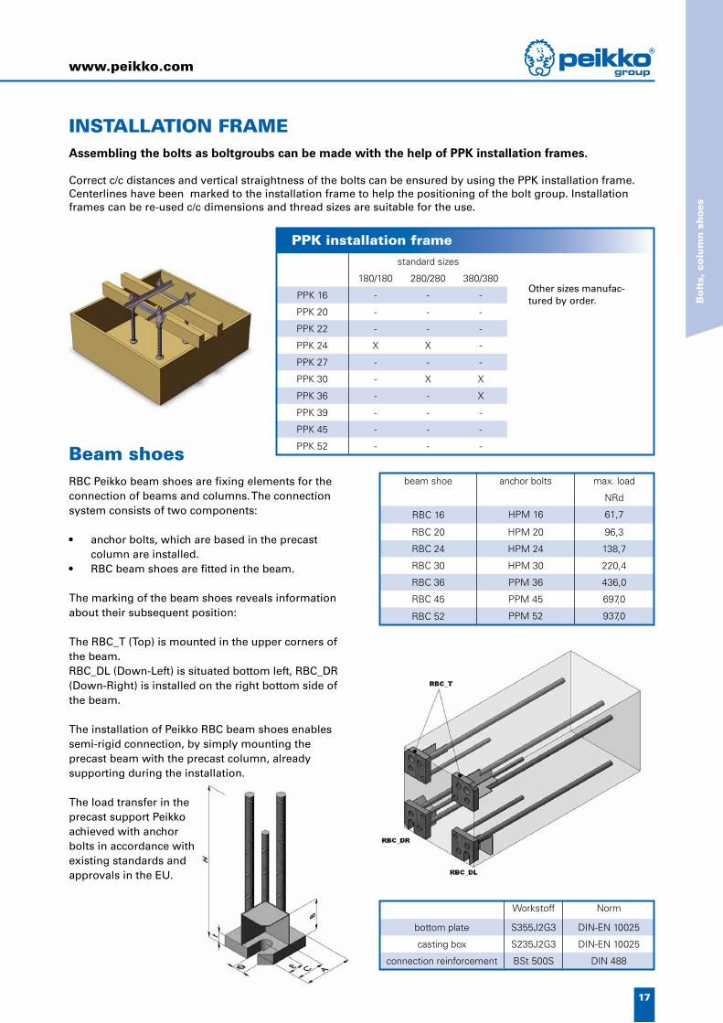
PPK 52 - - -Beam shoesRBC Peikko beam shoes are fixing elements for the connection of beams and columns. The connection system consists of two components:
• anchor bolts, which are based in the precast column are installed.
• RBC beam shoes are fitted in the beam.
The marking of the beam shoes reveals information about their subsequent position:
The RBC_T (Top) is mounted in the upper corners of the beam.RBC_DL (Down-Left) is situated bottom left, RBC_DR (Down-Right) is installed on the right bottom side of the beam.
The installation of Peikko RBC beam shoes enables semi-rigid connection, by simply mounting the precast beam with the precast column, already supporting during the installation.
The load transfer in the precast support Peikko achieved with anchor bolts in accordance with existing standards and approvals in the EU.
beam shoe anchor bolts max. load
NRd
RBC 16 HPM 16 61,7
RBC 20 HPM 20 96,3
RBC 24 HPM 24 138,7
RBC 30 HPM 30 220,4
RBC 36 PPM 36 436,0
RBC 45 PPM 45 697,0
RBC 52 PPM 52 937,0
Workstoff Norm
bottom plate S355J2G3 DIN-EN 10025
casting box S235J2G3 DIN-EN 10025
connection reinforcement BSt 500S DIN 488
PPK installation frame
INSTALLATION FRAMEAssembling the bolts as boltgroubs can be made with the help of PPK installation frames.
Correct c/c distances and vertical straightness of the bolts can be ensured by using the PPK installation frame. Centerlines have been marked to the installation frame to help the positioning of the bolt group. Installation frames can be re-used c/c dimensions and thread sizes are suitable for the use.
Other sizes manufac-tured by order.

18
PCs KONSOLI
Betoniyhdistyksen käyttöseloste nro 276 Korvaa esitteen 5/2006 • Väli 3, X/2008
3. CORBELS, HANGERS
Light corbel systemCORBEL SYSTEMSPCs corbel systemPCs corbel system is designed to support steel, composite and reinforced concrete beams to reinforced concrete columns and walls.
Light corbel systemLight corbel system can be used in e.g. supporting exterior wall, intermediate landing and balcony elements. Elements can be supported from in-situ cast or element frame.
System parts:
- corbel box- corbel fl at steel- support part for wall element - or support for fl oor slabs
(KL 120/190 pictured)
PCs corbel system
Connection consists of: - A column part and corbel parts- A link in beam’s end plate
(PC 3-H pictured)
Light corbel in sandwich-element (above) support and in intermediate landing (below).

19
www.peikko.com
Co
rbel
s, h
ang
ers
L B H weight
[mm] [kg]
K120 120 60 130 2,2
K190 190 60 153 3,7
K120PUR 120 140 146 4,4
Surface treatment options: paint / hot dip galvanized
L B H H2 weight
[mm] [kg]
KS120 80 100 90 80 1,6
KS190 80 120 110 80 1,9
(includes bolt, nut and two washers), always hot dip galvanized
L B B2 H weight
[mm] [kg]
KL120/190 567 158 170 200 6,0
Surface treatment options: paint / hot dip galvanized
L B H weight
[mm] [kg]
KA120 236 12 90 2,1
KA190 304 16 110 4,5
plates (≤ 6 mm) plates (> 6 mm)flat steel / square
sectionribbed bars
S235JR S355J0+N S355J0+N A500HW
in KS also neoprenes
H
L B
L
H2
H
B
L
BB2
H
H
L B
Light corbel K (corbel box)
Light corbel KS (for wall element)
Light corbel KL 120/190 (for floor slab)
Remember also square sections!Square section 120 12x12x115 HDG Square section 190 16x16x185 HDG
Materials of light corbel system
APPROVALS:BY280 Finland
LIGHT CORBEL SYSTEM
Light corbel KA (corbel piece)
Always hot dip galvanized

20
340
d=280
APPROVALS:BY276 Finland, POCC FI.C∏19.H00289 Russia
APPROVALS:BY210 Finland, POCC FI.C∏19.H00289 Russia
PCs corbel
PC beam shoe
PCs CORBEL SYSTEMPCs corbelThere are several types of corbels:• PCs basic model • PCs UP for column’s upper end • both before mentioned also double sided• all before mentioned with LOCK-corbel parts
PC beam shoeThere are two types of beam shoes:• PC – L for beams with low fl ange (fl ange’s
height < 60 mm) (e.g. PC 3-L)• PC – H for beams with high fl ange (fl ange’s
height ≥ 60 mm) (e.g. PC 3-H)
The beam shoe type differs in height. Type –L fi ts better low beams with steel fl ange and type –H fi ts better beams with concrete fl ange. In the case of a beam without a fl ange the shoe type and its location must be considered separately.
PCs UP (left) andPCs (right).
PCs corbels also available double sided.
PC H beam shoe on the left and PC L on the right.
Installation of PCsThe column part is installed to the casting mould together with reinforcements.
The corbel parts (a corbel plate, washers and bolts) are attached to the column after the element has been cast.
A link has to be made to the end plate of steel or composite beam for the corbel.
The beam is installed on the corbel by lowering the beam so that the corbel goes into the link in the beam’s end plate.
When using LOCK-corbel, the vertical thread bars should fi t through holes made for the LOCK-corbel in the beam’s top plate. Thread bars have to be long enough so that washers and nuts can be tightened properly after the beam is installed.
The whole height of the joint between the column, the beam and the space around the corbel parts is grouted at the same time as the joints of the slabs.
PCs 5-2 / d=280 UPLOCK 290 + LOCK 350
corbel’s load classdouble sided console (-2 /)
round column (d=)diameter / side length of column
model for negative support reaction (LOCK) and length of the vertical bar (see page 21)
Sections marked with blue, red and green are optional and independent from one another. Double-sided corbel is indicated with ”-2” followed by the diameter or side length of the column. In the case of a rectangularcolumn, “=d” is left off. If more than one LOCK-corbel part is needed (double-sided corbel), each is marked separately.
For example. pictured on right is PCs 3-2 / d=280 UP LOCK 340
How to form the product code for the PCs corbel
model for column’s to end (UP)

21
www.peikko.com
Co
rbel
s, h
ang
ers
plates (> 25 mm) plates (≤ 25 mm) ribbed bars screws washers
S355J2+N S355J0 A500HW property class 10.9 property class 10.9
thread H6 color
PCs 2 LOCK M16 31 red
PCs 3 LOCK M22 39 grey
PCs 5 LOCK M22 39 yellow
PCs 7 LOCK M22 39 green
PCs 10 LOCK M27 50 blue
PCs 15 LOCK M27 50 black
H1 L1 B1 H2 H3 L4 B2 d3 VRd TRd weight color
[mm] [kN] [kNm] [kg]
PCs 2 UP 155 76 60 210 397 125 116 16 220 8 12,2 red
PCs 3 UP 155 92 80 235 386 200 135 20 350 15 21,5 grey
PCs 5 UP 205 112 90 315 430 250 150 25 580 30 37,3 yellow
PCs 7 UP 225 112 110 350 423 210 212 32 715 55 57,3 green
PCs 10 UP 280 117 145 380 578 260 222 32 1015 75 84,5 blue
H1 L1 B1 H2 H3 L3 B2 d3 VRd TRd weight color
[mm] [kN] [kNm] [kg]
PCs 2 155 76 60 210 397 125 116 16 220 8 12,8 red
PCs 3 155 92 80 235 386 140 135 20 350 15 21,9 grey
PCs 5 205 112 90 315 430 150 150 25 580 30 38 yellow
PCs 7 225 112 110 350 423 145 212 32 715 55 58,4 green
PCs 10 280 117 145 380 578 160 222 32 1015 75 85,0 blue
PCs 15 280 122 220 380 578 260 282 32 1500 190 127,5 black
VRd TRd
[kN] [kNm]
220 8
350 15
580 30
715 55
1015 75
1500 190
VRd TRd
[kN] [kNm]
220 8
350 15
580 30
715 55
1015 75
B1
H2
H3
H3
t2
d3
H1
L1L3
B2
H2
H3
B1
t2
L4 L1
H1
d3
B2
100
L =
H6
Vud, neg
PCs corbel
PCs UP corbel
Materials of PCs ja PCs UP
• Lenght L must be given at the code of the console (see page 20)
• Lenght H6; see the PCs corbel manual• Vud,neg = 80 kN in all sizes of console
LOCK corbel parts
PCs corbel delivery includes column part, console plate, washer plate, nuts and HV -washers.

22
plates ribbed bars
PRK S355J0 A500HW
PRK stainless 1.4301 A500HW
PRK fully stainless 1.4301 B600KX
H1 H2 Ø weight
[mm] [kg]
PRK 200 200 162 12 (11) 13,5
PRK 265 265 162 12 (11) 15,3
PRK 320 320 282 12 (11) 17,3
plates ribbed bars
S355J0 A500HW
H1 B1 B2 L1 L4 t1 VRd weight color
[mm] [kN] [kg]
PC 3-L 270 150 150 110 1115 20 350 15,6 grey
PC 5-L 300 150 150 130 1175 25 580 23,7 yellow
PC 7-L 340 240 152 130 1270 25 715 35,0 green
PC 10-L 410 240 187 135 1290 25 1015 56,5 blue
H1 B1 B2 L1 L4 t1 VRd weight color
[mm] [kN] [kg]
PC 3-H 310 150 118 110 1115 20 350 16,1 grey
PC 5-H 340 150 128 130 1175 25 580 24,3 yellow
PC 7-H 380 240 152 130 1270 25 715 35,7 green
PC 10-H 450 240 187 135 1290 25 1015 59,6 blue
VRd
[kN]
350
580
715
1015
VRd
[kN]
350
580
715
1015
100
H1 H2
1190
300
Ø12
H1
t1
L1L4
B1
B2
PC 3-LPC 5-L
PC 7-LPC 10-L
B1
B2
H1
t1
L1L4
B1
B2
PC 3-HPC 5-H
B1
B2
PC 7-HPC 10-H
Ø weight
[kg]
PRK
PRK edge hanger for hollow core slabsWith the help of PRK edge hanger for hollow core slabs can e.g. balcony element be supported to hollow core slabs.
PC H beam shoe
PC L beam shoe
Materials of PC L beam shoe ja PC H beam shoe
Upcoming new sizes: PC 2-L and PC 15-L
Upcoming new sizes: PC 2-H and PC 15-H
Materials of PRK

23
www.peikko.com
Co
rbel
s, h
ang
ers
plates ribbed bars
S355J2+N A500HW
h1 h2 b1 b2 L2
[mm]
POK 150 150 150 120 100 130
POK 175 175 175 120 100 130
POK 200 200 200 120 100 130
POK 265 265 265 120 100 150
POK 320 320 320 140 100 150
POK 370 370 370 140 100 150
POK 200/370 200 370 140 100 150
POK 400 400 400 140 100 150
POK 500 500 500 140 100 150
L
h1 h2
b2
b1
L2
105
85
ø20
185
95150
70
POKONTELOLAATTAKANNAKE
Betoniyhdistyksen käyttöseloste nro 189Korvaa esitteen 5/2003 • Väli 3, 11/2006
POK slab hanger
POKPOK slab hanger for hollow core slabs has an L-shaped steel section, which is de-signed to to bear hollow core (HC) slab units around a fl oor opening.
In the erection stage, before grout-ing, POK slab hangers distribute loads from the supported HC slab to the units each side of it. After concreting the fl oor, the load from the HC slab is transferred by the POK slab hanger and also by the
Part weights 1,1 kg.
Material is S355J0 and it is hot dip galvanized.
APPROVALS::BY263 Finland, AT-15-5360/2002 Poland,POCC FI.C∏19.H00289 Russia
Peikkohanger
PEIKKOHANGERPeikkohanger is used in e.g. elevator shafts, stairways etc. Hanger acts as a fast support for handrails, working fl oors and riggers.
Capacity curves can be found at POK slab hanger’s manual.
Materials of POK
grouting joints between the units. POK hanger’s fi re resistance is up to 60 minutes. If higher fi re resist-ance ratings are needed, additional fi re protection has to be used.
Standard lengths (all models):
L=1200L=1800L=2400

24
520
210 21050
8020h
s
h lv
80
ts
ds
90120
50
hs ts h lv* dsVRd, assem-
bling**
[mm] [kN]
PBH 1 100 15 460 360 10 80
PBH 2 100 20 470 370 12 100
PBH 3 120 15 580 460 12 125
PBH 4 120 20 600 480 14 150
* lv can be adapted to constructive details and design
** In case hs ≤ 50 cm, VRd, assembling should be lowered according design values in PBH brochure
VRd, assem-
bling**
[kN]
80
100
125
150
PBH corbelPeikko PBH corbels are used to connect prefab TT elements to beams or to connect secondary to primary beams - without any additional and cost intensive concrete console. Usually special supports are not needed, either. During assembling time all loads can be conducted into the beam via the Peikko PBH corbel. In the fi nal state usually the capacity of the bearing area results from the concrete capacity (after the additinal reinforcement has been placed and the ad-ditional concrete ahas hardened) and the capacity of the PBH corbel.
All sizes, weights and capacities can be found as a printout in our PBH-brochure or as pdf-fi le on the website www.peikko.com
The capacity of the bearing-area results from the console’s capacity added to the capacity of the ferroconcrete-corbel.
Loads, which are added after the in-situ concrete has hardened must not exceed the values of VRd – VRd, assembling from the PHB-bruchure’s charts.
The advantages of the PBH corbel:• No consoles necessary at the beams• quick and easy formwork-process• Less reinforcement in the bearing-area
necessary• no notching of the beam• easier reinforcement• high capacities• legal security provided by the static certifi cation
of the LGA (Landesgewerbeanstalt Bayern), a public-law corporation based in Nuremberg, Germany
• easy dimensioning through Peikko capacity charts
• no additional support needed during assembling
PBH corbel

25
www.peikko.com
Co
rbel
s, h
ang
ers

26
internal bar external bar diagonal
PDM B500K B500K 1.4301
PD B500K B600KX 1.4301
PDR B600KX B600KX 1.4301
PPA B600KX B600KX B600KX
The material of the pin is B600KX
4. TIES
TIESTies are connecting reinforcement which allows the joining of sandwich panel’s concrete layers together.
PD diagonal tiesPD diagonal ties are designed to join sandwich panels concrete layers together in the height of the whole component.
PPA beam tiesBeam ties can be used in low structures e.g. door and window beams and also in low founda-tion elements.
Materials for ties
APPROVALS:BY265 Finland (ties), BY246 Finland (pin),POCC FI.C∏19.H00289 Russia
PPI connector pinPPI connector pins are used to join the concrete layers of the sadwich element together. The pins will not improve the compressive capacity of the load bear-ing concrete layer. Connector pin can be applied for example in styrox or urethane isolated element’s edges and openings.
Material is stainless ribbed bar B600KX.

27
www.peikko.com
Tie
s
H L Advisable insulation thickness
[mm]
PD 150 150 2400 90
PD 180 180 2400 120
PD 200 200 2400 140
PD 210 210 2400 150
PD 220 220 2400 160
PD 240** 240 2400 180
PD 260** 260 2400 200** = sold in 500 ties / pallet.
insulation thickness (installation angle) K25 K10
H perpendicular 45° angle Nk Nd Nk Nd
[mm] [kN]
PPI 170 170 80 - 7,0 3,5 3,8 1,9
PPI 190 190 100 - 7,0 3,5 3,8 1,9
PPI 210 210 120 - 7,0 3,5 3,8 1,9
PPI 230 230 140 80 7,0 3,5 3,8 1,9
PPI 250 250 160 100 7,0 3,5 3,8 1,9
H Advisable insulation thickness
[mm]
PPA 150 150 90
PPA 180 180 120
PPA 200 200 140
PPA 210 210 150
PPA 220 220 160
PPA 240 240 180
PPA 260 260 200
PPA 280 280 220
K25 K10
Nk Nd Nk Nd
[kN]
7,0 3,5 3,8 1,9
7,0 3,5 3,8 1,9
7,0 3,5 3,8 1,9
7,0 3,5 3,8 1,9
7,0 3,5 3,8 1,9
L
H
250
H
62
HØ4
So
ld in
fu
ll p
alle
ts, 7
50 t
ies
/ pal
let.
PPI connectorpin
So
ld in
fu
ll b
oxes
, 500
pcs
/ b
ox.
PPA beam tie
So
ld in
fu
ll p
alle
ts, 5
00 t
ies
/ pal
let.
PD diagonal tie
APPROVALS:BY246 Finland, POCC FI.C∏19.H00289 Russia

28
L1 L2 C Ø c/c B
[mm]
TSA 8/150/42 380 380 - 8 150 42
TSA 8/300/42 380 380 - 8 300 42
TSA 10/150/42 480 480 - 10 150 42
TSA 10/300/42 480 480 - 10 300 42
TSA and TSK 8/150/95 120 400 62 8 150 95
TSA and TSK 8/300/95 120 400 62 8 300 95
TSA and TSK 8/150/120 120 400 80 8 150 120
TSA and TSK 8/300/120 120 400 80 8 300 120
TSA and TSK 10/150/120 140 500 80 10 150 120
TSA and TSK 10/300/120 140 500 80 10 300 120
TSA and TSK 8/150/150 120 400 110 8 150 150
TSA and TSK 8/300/150 120 400 110 8 300 150
TSA and TSK 10/150/150 140 500 110 10 150 150
TSA and TSK 10/300/150 140 500 110 10 300 150
L=2400 in all models
40
B
c/c
ø
TSA xx/xxx/42
L2
C
40
B
ø
c/c
TSA xx/xxx/xxx
L1
øc/c
TSK xx/xxx/xxx
C
40B
L2
TS TYÖSAUMARAUDOITE
Korvaa esitteen 5/2001 • Väli 5, 11/2006
5. REINFORCEMENT PRODUCTS
Bended joint reinforcement
We also manufacture bended joint reinforcements that goes in wall consoles.
More information from our sales department.
TS joint reinforcement
TS JOIN T REINFORCEMENTTS joint reinforcement is a reinforcement block manufactured from zinc-coated sheet metal box and ribbed bars. It can be used for example in in-situ casted joints.

29
www.peikko.com
Rei
nfo
rcem
ent
pro
du
cts
Concrete grade
loop distribution c/c [mm]
250 300 350 400 450 500 550 600 650 700 750
K30 114,9 107,4 92,5 81,3 72,7 65,7 60,0 55,3 51,3 47,8 44,9
K35 124,1 116,0 99,9 87,9 78,5 71,0 64,8 59,7 55,4 51,7 48,5
K40 132,7 124,0 106,8 93,9 83,9 75,9 69,3 63,8 59,2 55,2 51,8
K45 140,8 131,5 113,3 99,6 89,0 80,5 73,5 67,7 62,8 58,6 54,9
L1 L2 B H SL Ø
[mm]
PVL 80 160 212 50 20 80 6
PVL 100 160 212 50 20 100 6
PVL 120 190 212 50 20 120 6
loop distribution c/c [mm]
250 300 350 400 450 500 550 600 650 700 750
114,9 107,4 92,5 81,3 72,7 65,7 60,0 55,3 51,3 47,8 44,9
124,1 116,0 99,9 87,9 78,5 71,0 64,8 59,7 55,4 51,7 48,5
132,7 124,0 106,8 93,9 83,9 75,9 69,3 63,8 59,2 55,2 51,8
140,8 131,5 113,3 99,6 89,0 80,5 73,5 67,7 62,8 58,6 54,9
L2B
SL
H
L1
PVL CONNECTING LOOPPVL connecting loop is made of high strenght wire cable and galvanized sheet metal box. It can be used e.g. in conrete wall elements with vertical casting joints.
PVL connecting loop transfers shearing forces direct-ed to casting joint with the wire cable and concrete dovel from one component to the other.
APPROVALS:BY254 Finland
Capacity value for shearing force [kN/m]
PVL connecting loop

30
Item name
EFS M8x40
EFS M10x15
EFS M12x70
EFS M16x80
Item name
EFS-NP M12x70
EFS-NP M16x100
Item name
EFS-B M16x80
EFS-B M20x95
Item name
EFS-BNP M16x80
EFS-BNP M20x95
Galvanized, M thread size x part lenght
Item name
WFS M6x35
WFS M8x40
WFS M10x40
WFS M10x50
WFS M12x60
WFS M12x70
Item name
WFS-NP M6X35
WFS-NP M8X40
WFS-NP M10X40
WFS-NP M10X50
WFS-NP M12X60
l hs dh weight
[mm] [kg]
HFS M12x50 50 41 40 0,1
HFS M12x70 70 61 40 0,1
HFS M16x50 50 39 50 0,2
HFS M16x90 90 79 50 0,2
lhs
dh
Galvanized, M thread size x part lenght
EFS-B eye fixing socket + bolt
Sold in 50 pcs / bag
Galvanized, M thread size x part lenght
Galvanized, M thread size x part lenght
HFS fixing anchor
APPROVALS:BY267 Finland
Fixing anchorsFixing anchors are fixing parts with female thread that can be used for temporary and permanent fixings.
EFS eye fixing socket EFS-NP eye fixing socket + nail plate
EFS-BNP eye fix. socket + bolt + np.
WFS wavy end fixing socket
Galvanized, M thread size x part lenght
WFS wavy end fixing socket
Galvanized, M thread size x part lenght

31
www.peikko.com
Rei
nfo
rcem
ent
pro
du
cts
L1 L2 Ø c/c material weight/pcs pcs/
[mm] [kg] bundle
5-150, 5000x2350 5000 2350 5 150 B500K 24,62 40
5-150, 4000x2920 4000 2920 5 150 B500K 24,46 40
5-200, 5000x2350 5000 2350 5 200 B500K 18,29 40
6-150, 5000x2350 5000 2350 6 150 B500K 35,50 40
6-200, 5000x2350 5000 2350 6 200 B500K 26,36 40
8-150, 5000x2350 5000 2350 8 150 B500K 63,16 25
8-200, 5000x2350 5000 2350 8 200 B500K 46,91 25
10-150, 5000x2350 5000 2350 10 150 B500K 98,66 15
10-200, 5000x2350 5000 2350 10 200 B500K 73,27 20
4-150 4000x2920 4000 2920 4 150 B600KX 15,88 50
5-150 4000x2920 4000 2920 5 150 B600KX 24,46 40
7-150 5000x2350 5000 2350 7 150 B600KX 48,30 25
Øavailable lengths
[mm]
4,0 4000
5,0 4000 and 6000
7,0 6000 and 12000
9,0 6000 and 12000
ØAnnealed and fixed, soft
[mm]
0,9 wire tie L=300, 350 and 400 mm
4,0 coil, 25 kg / coil and 10 kg / coil
4,0 mason’s clamp L=350, 400, 450, 500 and 600 mm
10,0 L=4000 (std. bundle 250 kg)
12,0 L=4000 (std. bundle 250 kg)
16,0 L=6000 (std. bundle 500 kg)
20,0 L=4000 and 6000
25,0 L=4000 and 6000
L2
c/c
ø
c/c
L1
Meshes
stainless
stainless
stainless
Mesh
We make to order also stainless special meshes. Diameters: Ø4, Ø5, Ø7 and Ø9
Stainless ribbed and round bars
Hot rolled stainless ribbed bars from storage: Ø16, Ø20, Ø25, Ø32 and Ø40. Also ribbed and round bars cut for fixed sizes.
Stainless round bar 1.4301
Stainless ribbed bar B600KX
Stainless rebar coil
Stainless rebar coils available in the following sizes: Ø5, Ø7, Ø9 and Ø11.
Reinforcement meshes and stainless rebarReinforcement meshes can be used as reinforce-ments in floors and building facings.
Stainless rebar and meshes long-lasting reinforce-ments for exterior structures.
Marking of rebar
Marking in rebar manufactured by Peikko (6+6+2)

32
PSB punching reinforcementPSB elements are used as punching reinforcement. The elements consists of double headed ribbed bar studs welded to a spacer bar. Elements are preferably put in from the top after laying the fl at slab reinforcement. PSB elements are supplied as standard elements, which are available off stock or in short delay, and as complete elements, which are manufactured to measure on demand. The standard options are 2 stud and 3 stud elements which can be combined to form 4-, 5-, 6 stud assemblies etc. The symmetrical arrangement of the PSB studs on each element guarantees correct installation.
Advantages:
• planar ground fl oor• low slab thickness• applicable from 180 mm slab thickness• easy and time-saving installation• reduced mould consumption• increase of the bearing capacity• short delivery time• custom made demands
Type PSB-U: installation from the bottomIt is possible to install the PSB elements from the bottom, before placing the reinforcement of the slab. In this case the type PSB-U guarantees a secure posi-tion on the slab mould, because of the two installa-tion bars, which are fastened on its bottom.
For more information please contact our technical support.
PSB is made of BSt500S
APPROVALS:
WR-Z-070705 Austria,060-025271 Czech,Z-15.1-201 Germany,PSE-EME Hungary
PSB
The complete PSB elements are designed with 3 and more double headed ribbed anchors welded to a spacer bar at individual spacings on demand. Complete elements are ideal for the installation from “below”; i.e. the elements are placed on the formwork by special spacers. The lower and upper reinforcements are then put into position.

33
www.peikko.com
Rei
nfo
rcem
ent
pro
du
cts
Concentrated support of slabs without enlarged column headsSteel concrete flat slabs without beams and without enlarged column heads are regarded as economical construction and provide good conditions for an optimum use of space and an easy installation of additional devices.
The solution: PSB PUNCHING REINFORCEMENTThe PSB punching reinforcement consists of double head studs (BSt500S) with forged heads. An assembly bar on which the stud heads are welded combines the single studs to form punching elements.
Inserted from the topThe PSB punching reinforcement elements are preferably inserted from the top after laying the reinforcement. Adjustments of the position can be made without any problems.
The problem: Load distribution around the columnsThe load concentration around the columns generally leads to high shear loads which are not allowed according to DIN 1045-1.
Punching of the column head
UneconomicTo avoid punching the choice is often uneconomic and inconvenient solutions such as for example.
Enlargement of the column heads (above) and increase of the slab thickness (below).
These measures reduce the usable floor heights and thus the use of the construction is restricted.
How to orderPSB - 14 / 265 - 3 / 552 ( 130 / 130 / 195 / 97 )
TypeAnchor Ø[mm]Anchor height [mm]Anchor per elementtot.lenght of the element [mm]Distance of the support edge/angleDistance 1. AnchorDistance 2. Anchor...Distance last Anchor — dip end

34
MODIX SM – Standard Muffs SM A+BFor connection of rebars with equal diameter.Other rebar must be able to rotate free.
MODIX PM – “Positions Muff”Connection part for rebars which are both fi xed to reinforcement. Rebars can be bent or straight. Rebars must be axially in line.
MODIX RM – “Reduction Muff”For the connection of rebars with different diameters. Other rebar must be able to rotate free.
MODIX KM – “Kombination Muff”For fastening the female coupler to structures with metric screw. KM ring is installed be-tween the muff and the screw.
MODIX EM – “End anchoring Muff”Part for anchoring the coupled rebar to con-crete without using a hook.
MODIX AM – “A weldable Muff”AM muff can be welded to structures to fasten the coupled rebar.
MODIX rebar splicing systemIn structures which have heavy reinforcement with small center to center distances, splicing rebars are wasting valuable space from concrete. In concreting joints, continuing the reinforcement can be dif-fi cult through the formwork, and creating rigid column to beam connections is complex with continu-ous reinforcement. These problems can be solved by using industrially made and approved end to end threaded connections. Peikko® MODIX system is a state of the art rebar coupling system. Check the Approval status and supplier network from local sales.
Peikko® MODIX rebar splicing systems is available for rebar sizes d12 - d32. System consists of female and male thread muffs and connectors. Due to unique design installation does not require special tools to ensure proper tightness of the connection - normal pipe wrenches will do the work just fi ne. Various lengths and bendings available upon order.
Muff types

35
www.peikko.com
Rei
nfo
rcem
ent
pro
du
cts
MODIX size (d) [mm]
colorProtective cap with thread for A muff
Protective plug B muff Plastic installation plateMagnetic installation
plate
10 orange
12 yellow
14 blue
16 white
20 grey
25 red
28 black
32 brown
Delivery: With muff With muff By order By order
Accessories

36
JENKA socket anchor lifting systemJENKA product range consists of various Rd-threaded socket anchors with capacities from 500 kg to 12,5 tons, threaded lifting loops and various accessories.
JENKA -anchors are suitable also for narrow and thin structures. WAS and WAL are for re-duced anchoring depth, SRA for narrow struc-tures and CSA to arrange bonding with sepa-rate rebar. JENKA anchors are delivered with zinc plated sockets and plain rebars.
Contact local sales for more detailed informa-tion.
CSA crosshole socket anchor
BSA bolt socket anchor ESA eye socket anchor
PSA plate socket anchor
Item name: CSA Rd thread size (d)
Item name: BSA Rd thread size
Item name: ESA Rd thread size
Item name: PSA Rd thread size
Item nameLoad class
[kg]Length [mm]
CSA 12 500 40
CSA 14 800 47
CSA 16 1200 55
CSA 18 1600 65
CSA 20 2000 67
CSA 24 2500 77
CSA 30 4000 105
CSA 36 6300 125
CSA 42 8000 145
CSA 52 12500 195
Item nameLoad class
[kg]Length [mm]
BSA 12 500 60
BSA 14 800 70
BSA 16 1200 80
BSA 18 1600 90
BSA 20 2000 100
BSA 24 2500 115
BSA 30 4000 150
Item nameLoad class
[kg]Length [mm]
ESA 12 500 60
ESA 14 800 70
ESA 16 1200 77
ESA 18 1600 85
ESA 20 2000 92
ESA 24 2500 105
Item nameLoad class
[kg]Length [mm]
PSA 12 500 30
PSA 14 800 33
PSA 16 1200 35
PSA 18 1600 44
PSA 20 2000 47
PSA 24 2500 54
PSA 30 4000 72
PSA 36 6300 84
PSA 42 8000 98
PSA 52 12500 117
d
6. LIFTING SYSTEMS

37
www.peikko.com
Lift
ing
sys
tem
s
Item name Load class [kg]
SRA 12X195 500
SRA 14X235 800
SRA 16X275 1200
SRA 18X305 1600
SRA 20X360 2000
SRA 24X400 2500
SRA 30X505 4000
SRA 36X690 6300
SRA 42X840 8000
SRA 52X950 12500
Item name Load class [kg]
WAS 12X105 500
WAS 14X130 800
WAS 16X165 1200
WAS 18X175 1600
WAS 20X195 2000
WAS 24X240 2500
WAS 30X300 4000
WAS 36X380 6300
WAS 42X450 8000
Item name Load class [kg]
TF 12X100 500
TF 12X150 500
TF 14X105 800
TF 14X155 800
TF 16X130 1200
TF 16X175 1200
TF 18X150 1600
TF 18X225 1600
TF 20X185 2000
TF 20X250 2000
TF 24X200 2500
TF 24X275 2500
TF 30X275 4000
TF 30X350 4000
TF 36X335 6300
TF 36X450 6300
TF 42X385 8000
TF 42X500 8000
TF 52X550 12500
TF 52X700 12500
Item name Load class [kg]
WAL 12X135 500
WAL 14X170 800
WAL 16X215 1200
WAL 18X235 1600
WAL 20X270 2000
WAL 24X350 2500
WAL 30X450 4000
WAL 36X570 6300
WAL 42X620 8000
WAL 52X880 12500
Rd thread size
Load class [kg]
12 500
14 800
16 1200
18 1600
20 2000
24 2500
30 4000
36 6300
42 8000
52 12500
d
h
SRA straight rebar anchor
WAS short wawytail anchor TF “Trollfoot”
WAL long wawytail anchor
d
h
Item name: SRA Rd thread size (d) x length (h) [mm]
Item name: WAS Rd thread size (d) x length (h) [mm]
Item name: TF Rd thread size (d) x length [mm]
Item name: WAL Rd thread size (d) x length (h) [mm]
TLL threaded lifting loopMax. lifting agle 45°. Available in sizes TLL 12 - TLL 52. Rd thread.
JL “JENKA lifter”Only to be used with NPP mould fi xing. Avail-able in sizes JL 12 - JL 52. Rd thread.
TLL and JL lifting devices are com-patible with JENKA and PLA anchors.
Lifting devices (JENKA, PLA)

38
inner thread coupler ribbed bar
1.4301 / 1.4305 A500HW / Bst500S
D Rd ds dt e h K20 weight
[mm] Fperm [kN] [kg]
PLA 20 30 20 20 58 35 140 20 0,3
PLA 24 35 24 20 58 43 150 25 0,4
PLA 30 40 30 25 72 56 200 40 0,6
PLA 36 50 36 32 96 68 250 63 1,3Fperm = permissible load
K20
Fperm [kN]
20
25
40
63
RdD
e
hds
dt
CPP Plastic cap For JENKA and PLA anchors. Concrete grey color, no threads, is pressed down. Available in sizes CPP 12 - CPP 52. Sold in 100 pcs packages.
JID JENKA identifi cation ring For JENKA anchors. Colour-coded plastic ring with the defi nition of load class. Remains visible in the element. Available in sizes JID 12 - JID 52. Sold in 100 pcs packages.
JFR JENKA fi xing ring Similar to JID, but has clips for reinforcement. Plastic, colour-coded. Available in sizes JFR 12 - JFR 52.
Other supplies (JENKA, PLA)Installation fi xings (JENKA, PLA)
Installation fi xings for wood and metal moulds
NPP plastic nail plateFixed by nailing trough the plate into the mould. Compatible with JL “JENKA lifter”. Available in sizes NPP 12 - NPP 52 (Rd).
NNP narrow nail plateFixed by nailing trough the plate into the mould. Material: plastic. Available in thread sizes M12 - M52 (M thread).
NPM magnetic holderFastens with magnet. Available in sizes NPM 12 - NPM 42 (Rd).
PLA lifting anchorPLA lifting anchors are lifting parts for lifting balcony slabs from stainless thread. The lifting is done by Rd threaded lifting loop or lifting device. Inner thread is anchored to concrete with the help of headed stud.
After installing the element the lifting anchor needs no mortar fi lling. Hole can be blocked by plastic cap.
See lifting devices on page 37.
Note: Anchors’ load groups/classes refer to anchor’s steel tensile strength. Capacity marked to the anchor is the Safe Working Load with safety factor 3 for the steel part only. Anchor’s actual capacity and safe working load when installed into concrete must be checked from user instructions available from local sales.
PLA lifting anchor
APPROVALS:BY233 Finland

39
www.peikko.com
Lift
ing
sys
tem
s
ribbed bar tube pin
B600KX 1.4301 1.4301 / B600KX
fl at steel ribbed bar
1.4301 1.4301
H a c ø K40-1* weight
[mm] Fperm [kN] [kg]
RRPr 2 440 10 30 11 3,5 1,0
RRPr 4 550 15 40 16 10,0 2,4
* = design strenght of concrete Fperm = permissible load
L Ø Fperm weight
[mm] [kN] [kg]
PNLF 1 600 1 Ø 7 11,7 1,0
PNLF 2 770 1 Ø 9 19,3 1,5
PNLF 3 940 1 Ø 11 28,8 2,3
PNLF 4 920 2 Ø 9 32,8 3,2
PNLF 5 1120 2 Ø 11 48,2 5,3
PNLF 6 1350 3 Ø 11 72,0 8,7
Fperm = permissible load
K40-1*
Fperm [kN]
3,5
10,0
Fperm
[kN]
11,7
19,3
28,8
32,8
48,2
72,0
øL
c
H
ø
a
PNLF lifting anchorPNLF is designed for lifting anchors of sandwich elements. PNLF is fully stainless.
PNLF lifting anchor
RRPr column’s lifting partRRPr is stainless steel part for lifting columns. It is specially for fl oor height’s balcony columns.
RRPr is used for lifting up (from horizontal position) and placing smaller columns. The part is left to the column after installation. It acts transversal anchor for balcony slab.
RRPr column’s lifting part
APPROVALS:BY217 Finland

40
Item name Load class [tons] Unit weight [kg]
KKL 13 1,3 0.9
KKL 25 2,0 -2,5 1.5
KKL 50 4,0 - 5,0 3.2
KKL 100 7,5 - 10 9.4
KKL 200 20 20.0
KKL 320 32 45.5
Item name for load class color
KRC 13 1,3 blue
KRC 25 2,0 -2,5 yellow
KRC 50 4,0 - 5,0 blue
KRC 75 7,5 red
KRC 100 10 yellow
KRC 150 15 grey
KRC 200 20 black
KRC 320 32 grey
Item name Load class [tons] Length h [mm]
KK 1,3 1,3 40-240
KK 2,5 2,5 45-280
KK 4,0 4,0 75-420
KK 5,0 5,0 65-480
KK 7,5 7,5 95-680
KK 10 10 115-680
KK 15 15 140-840
KK 20 20 200-1000
KK 32 32 200-1200
Item name for load class
KFS 13 1,3
KFS 25 2,0 -2,5
KFS 50 4,0 - 5,0
KFS 75 7,5
KFS 100 10
KFS 150 15
KFS 200 20
KFS 320 32
h
KK lifting systemKK lifting system is a rapid release lifting anchor system consisting of anchors of load classes from 1,3 to 32 tons, lifting clutches and recess formers. It is used for lifting beams, thick slabs and wall panels as well as concrete tubes.
Standard anchors are delivered as plain “black”. Hot dip galvanized (HDG) or electro galvanized mod-els are available on customer request. Contact local sales for more detailed information.
Note: Anchors’ load groups/classes refer to anchor’s steel tensile strength. Capacity marked to the anchor is the Safe Working Load with safety factor 3 for the steel part only. Anchor’s actual capacity and safe working load when installed into concrete must be checked from user instructions available from local sales.
KKL lifting clutch
For KK-lifting anchors
KKL lifting clutch is a heady duty lifting device for continuous use for load classes from 1,3 – 32 tons.
KRC recess former
KFS recess fi xing screw
Color coded rubber re-cess former for KK-lifting system.
Available for load classes 1,3 – 32 tons
For fi xing KRC recess former to casting mould.
Available for load classes 1,3 – 32 tons
KK-anchor
Available for load classes 1,3 to 32 tons in various lengths.

41
www.peikko.com
Lift
ing
sys
tem
s
Item name for load class
KMR 13 1,3
KMR 25 2,0 -2,5
KMR 50 4,0 - 5,0
KMR 75 7,5
For load class Item name Color
2,5 RR-RF-2,5 Orange
5,0 RR-RF-5,0 Black
10,0 RR-RF-10,0 Green
26,0 RR-RF-26,0 Blue
For load class Item name
2,5 RR-HP-2,5
5,0 RR-HP-5,0
10,0 RR-HP-10,0
Item name for load class
KMG 13 1.3
KMG 25 2,0 -2,5
KMG 50 4,0 - 5,0
KMG 75 7.5
Load class [tons]
Item name
2,5 RR-C-2,5
5,0 RR-C-5,0
10,0 RR-C-10,0
KMR magnetic recess former KMG magnetic recess grommet
Magnetic recess former for KK-lifting system
Available for load classes 1,3 – 7,5 tons
Magnetic recess grom-met. For use with KMR. Material: rubber.
RR lifting lugsRR lifting lugs are lifting parts for precast elements. They are used together with dedicated lifting devices.
Lifting device (RR lifting lugs)
Lifting device for “RR” line of lifting lugs (including RRPr)
RR supplies
RR-RF recess former For RR system. Color-coded.
RR-HPFor fi xing RR-RF into mould.
Note: Anchors’ load groups/classes refer to anchor’s steel tensile strength. Capacity marked to the anchor is the Safe Working Load with safety factor 3 for the steel part only. Anchor’s actual capacity and safe working load when installed into concrete must be checked from user instructions available from local sales.
42
Load class [tons]
Item nameLength [mm]
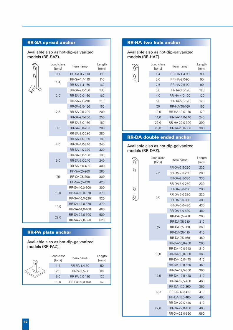
1,4 RR-HA-1,4-90 90
2,0 RR-HA-2,0-90 90
2,5 RR-HA-2,5-90 90
3,0 RR-HA-3,0-120 120
4,0 RR-HA-4,0-120 120
5,0 RR-HA-5,0-120 120
7,5 RR-HA-7,5-160 160
10,0 RR-HA-10,0-170 170
14,0 RR-HA-14,0-240 240
22,0 RR-HA-22,0-300 300
26,0 RR-HA-26,0-300 300
Load class [tons]
Item nameLength [mm]
0,7 RR-SA-0,7-110 110
1,4RR-SA-1,4-110 110
RR-SA-1,4-160 160
2,0
RR-SA-2,0-130 130
RR-SA-2,0-160 160
RR-SA-2,0-210 210
2,5
RR-SA-2,5-150 150
RR-SA-2,5-200 200
RR-SA-2,5-250 250
3,0
RR-SA-3,0-160 160
RR-SA-3,0-200 200
RR-SA-3,0-280 280
4,0
RR-SA-4,0-180 180
RR-SA-4,0-240 240
RR-SA-4,0-320 320
5,0
RR-SA-5,0-180 180
RR-SA-5,0-240 240
RR-SA-5,0-400 400
7,5
RR-SA-7,5-260 260
RR-SA-7,5-300 300
RR-SA-7,5-420 420
10,0
RR-SA-10,0-300 300
RR-SA-10,0-370 370
RR-SA-10,0-520 520
14,0RR-SA-14,0-370 370
RR-SA-14,0-460 460
22,0RR-SA-22,0-500 500
RR-SA-22,0-620 620
Load class [tons]
Item nameLength [mm]
1,4 RR-PA-1,4-50 50
2,5 RR-PA-2,5-80 80
5,0 RR-PA-5,0-120 120
10,0 RR-PA-10,0-160 160
Load class [tons]
Item nameLength [mm]
2,5
RR-DA-2,5-230 230
RR-DA-2,5-280 280
RR-DA-2,5-330 330
5,0
RR-DA-5,0-230 230
RR-DA-5,0-280 280
RR-DA-5,0-330 330
RR-DA-5,0-380 380
RR-DA-5,0-430 430
RR-DA-5,0-480 480
7,5
RR-DA-7,5-260 260
RR-DA-7,5-310 310
RR-DA-7,5-360 360
RR-DA-7,5-410 410
RR-DA-7,5-460 460
10,0
RR-DA-10,0-260 260
RR-DA-10,0-310 310
RR-DA-10,0-360 360
RR-DA-10,0-410 410
RR-DA-10,0-460 460
12,5
RR-DA-12,5-360 360
RR-DA-12,5-410 410
RR-DA-12,5-460 460
17,0
RR-DA-17,0-360 360
RR-DA-17,0-410 410
RR-DA-17,0-460 460
22,0
RR-DA-22,0-410 410
RR-DA-22,0-460 460
RR-DA-22,0-560 560
RR-SA spread anchor RR-HA two hole anchor
RR-PA plate anchor
RR-DA double ended anchor
Available also as hot-dip-galvanized models (RR-SAZ).
Available also as hot-dip-galvanized models (RR-HAZ).
Available also as hot-dip-galvanized models (RR-PAZ).
Available also as hot-dip-galvanized models (RR-DAZ).

43
www.peikko.com
Lift
ing
sys
tem
s
RR RR stainless RRK RRK stainless
fl at steel S355J0 1.4301 S355J0 1.4301
plate S355J0 1.4301 - -
angle bar - - S235JR 1.4301
Surface treatment of non stainless models: painted / hot dip galvanized
Load class [tons]
Item nameLength [mm]
1,4 RR-EA-1,4-200 200
2,5 RR-EA-2,5-230 230
4,0 RR-EA-4,0-270 270
5,0 RR-EA-5,0-290 290
7,5 RR-EA-7,5-320 320
10,0 RR-EA-10,0-390 390
12,5 RR-EA-12,5-500 500
17,0 RR-EA-17,0-500 500
22,0 RR-EA-22,0-500 500
Load class [tons]
Item nameLength [mm]
0,7 RR-FA-0,7-60 65
1,4 RR-FA-1,4-60 65
2,0 RR-FA-2,0-70 70
2,5 RR-FA-2,5-70 75
3,0 RR-FA-3,0-90 90
4,0 RR-FA-4,0-110 110
5,0 RR-FA-5,0-120 125
7,5 RR-FA-7,5-170 170
10,0 RR-FA-10,0-200 200
12,5 RR-FA-12,5-220 220
17,0 RR-FA-17,0-270 270
22,0 RR-FA-22,0-310 310
L B H a c K20** K30** K40** RR
[mm] Fperm [kN] [kg]
RR 2 80 80 108 10 30 17,6 17,6 17,6 0,5
RR 4 100 100 117 15 40 24,1 31,6 37,6 1,1
RR 2/53 80 80 53 10 30 7,6 10,0 12,1 0,4
RR 4/68 100 100 68 15 40 11,9 15,5 18,8 0,9
** = concrete strenght at the time of lifting Fperm = permissible load acc. to Finnish Building Code
L B H a c angle bar K20** K30** K40** RRK
[mm] Fperm [kN] [kg]
RRK 2 100 60 108 10 30 60x60x6 15,5 17,6 17,6 0,8
RRK 4 150 80 140 15 40 80x80x8 29,3 37,6 37,6 2,0
** = concrete strenght at the time of lifting Fperm = permissible load acc. to Finnish Building Code
K20** K30** K40**
Fperm [kN]
17,6 17,6 17,6
24,1 31,6 37,6
7,6 10,0 12,1
11,9 15,5 18,8
K20** K30** K40**
Fperm [kN]
15,5 17,6 17,6
29,3 37,6 37,6
H
c
B
a
L
B
H
c
L
a
RR-FA fl at foot anchorRR-EA erection anchor
Available also as hot-dip-galvanized models (RR-FAZ).
Available also as hot-dip-galvanized models (RR-EAZ).
RR lifting lug
RRK lifting lug
Materials of RR, RRK
APPROVALS:BY264 Finland
APPROVALS:BY264 Finland
RR is a lifting part for precast slabs. RRK is designed to be used on slab edges. RR and RRK have Finnish approvals.

44
P4X KAIDELIITOS
Betoniyhdistyksen käyttöseloste nro 234Korvaa esitteen 2/2001 • Väli 7, 5/2006
7. BALCONY JOINTS
P4X railing connection
P4X RAILING CONNECTIONWith P4X railing connection reinforced concrete railing can be fastened reinforced to concrete balcony slab. Connection con-sists of three components:
• railing par• slab part• connection parts (C rail,
washer plate, hex screws)
The slab part anchors to the balcony slab with help of its ribbed bars.
Separate connection parts are fastened to slab part with screws in element factory or building site.
Railing part anchors with help of headed studs. After railing installation the joint transfers the loads to balcony slab trough slab part.
The railing part has screws in it that are used for stiffening the connection.
P4X can be used also for fastening glass railings.
PS balcony hinge
Fully stainless
Connecting P4 connection parts
P4X railing connection
P4X slab part
The model has improved with bended rebars which helps the installing of the part.
APPROVALS:BY234 Finland

45
www.peikko.com
Bal
cony
join
ts
fl at steel 1.4301
plate 1.4301
threaded coupler 1.4301
headed stud 1.4301
ribbed bar B600KX
C-rail 1.4301
screw ISO 7380 1.4301
plates sleeve ribbed bar
1.4301 1.4301 B600KX
A NRd VRd weight
[mm] [kN] [kg]
PS 110 110 25 8 4,7
PS 170 170 25 8 5,0
NRd VRd
[kN]
25 8
25 8
190
105
98
110 160150
20
35
81
170
62
30
C-RAIL
8
70
A200 170 200
250ø7
110
373
160
160
40 5
WASHER
PS balcony hinge
P4 railing part
P4X slab part
The delivery in-cludes C rail, 2 hex screws and a washer plate.
P4 connection parts
Materials P4
APPROVALS:BY247 Finland,POCC FI.C∏19.H00289 Russia.
Railing part
4 pcs of hex screws is included in the price.
One items weight is1,5 kg.
Slab part
46
8. EXPANSION JOINTS
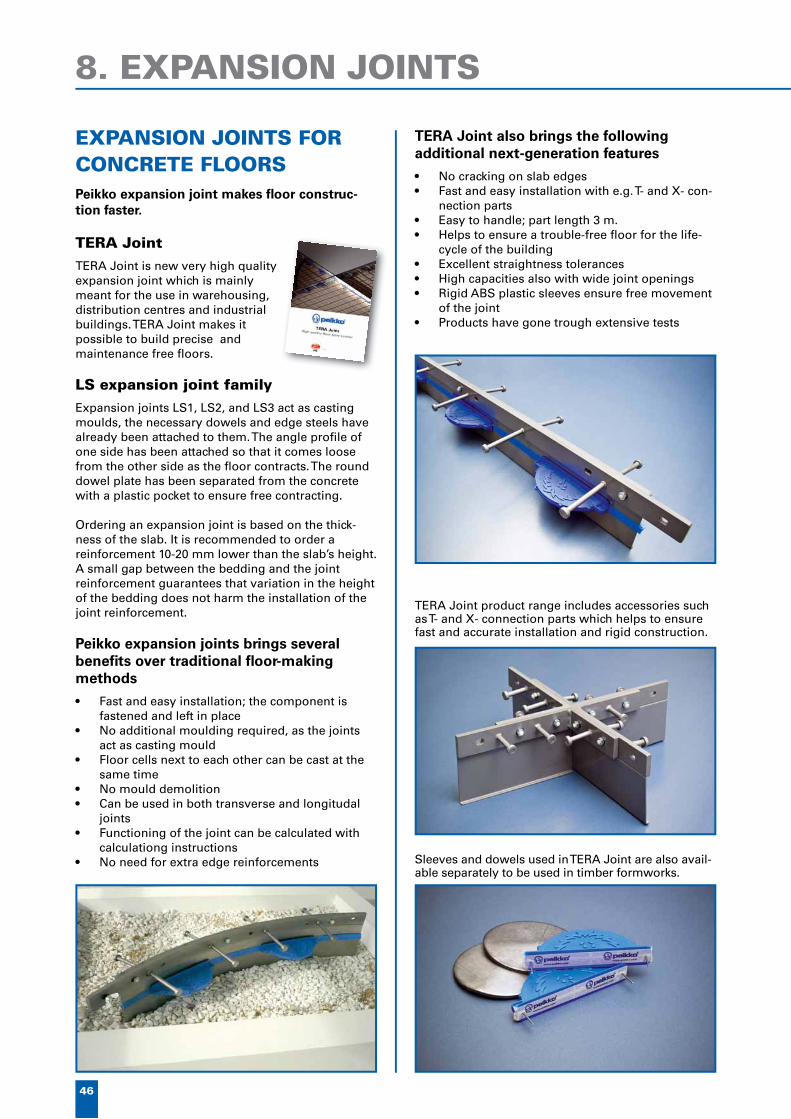
EXPANSION JOINTS FOR CONCRETE FLOORSPeikko expansion joint makes fl oor construc-tion faster.
TERA JointTERA Joint is new very high quality expansion joint which is mainly meant for the use in warehousing, distribution centres and industrial buildings. TERA Joint makes it possible to build precise and maintenance free fl oors.
LS expansion joint familyExpansion joints LS1, LS2, and LS3 act as casting moulds, the necessary dowels and edge steels have already been attached to them. The angle profi le of one side has been attached so that it comes loose from the other side as the fl oor contracts. The round dowel plate has been separated from the concrete with a plastic pocket to ensure free contracting.
Ordering an expansion joint is based on the thick-ness of the slab. It is recommended to order a reinforcement 10-20 mm lower than the slab’s height. A small gap between the bedding and the joint reinforcement guarantees that variation in the height of the bedding does not harm the installation of the joint reinforcement.
Peikko expansion joints brings several benefi ts over traditional fl oor-making methods
• Fast and easy installation; the component is fastened and left in place
• No additional moulding required, as the joints act as casting mould
• Floor cells next to each other can be cast at the same time
• No mould demolition• Can be used in both transverse and longitudal
joints• Functioning of the joint can be calculated with
calculationg instructions• No need for extra edge reinforcements
TERA Joint also brings the following additional next-generation features
• No cracking on slab edges• Fast and easy installation with e.g. T- and X- con-
nection parts• Easy to handle; part length 3 m.• Helps to ensure a trouble-free fl oor for the life-
cycle of the building• Excellent straightness tolerances• High capacities also with wide joint openings• Rigid ABS plastic sleeves ensure free movement
of the joint• Products have gone trough extensive tests
TERA Joint product range includes accessories such as T- and X- connection parts which helps to ensure fast and accurate installation and rigid construction.
Sleeves and dowels used in TERA Joint are also avail-able separately to be used in timber formworks.

47
www.peikko.com
Exp
ansi
on
jo
ints
TERA Joint is designed for high-pre-cision floors that needs to remain maintenance free under de-manding use, such as logistic warehouses.
TERA Joints are manufac-tured for slab thicknesses 100-300 mm. Lenght 3 m.
NEW: TERA Joint
Expansion joints work also as a casting mould, replacing separate dowels and edge steels.
Remember also Peikko’s reinforcement meshes! See page 31.
TFX - Installation device TERA Joint

48
dovel thickness t dovel diameter d sleeve type advisable joint opening
[mm] [mm]
TJD-C6 6 150 TJS-C6 0-15
TJD-C12 6+6 150 TJS-C12 15-20
height h dowel dowel centres c/c length L weight advisable slab
thickness
[mm] [kg] [mm]
TJ6-90-3000 90 6 x d150 375 3000 31,2 100-120
TJ6-115-3000 115 6 x d150 375 3000 32,4 125-140
TJ6-135-3000 135 6 x d150 375 3000 33,9 145-165
TJ6-160-3000 160 6 x d150 375 3000 35,1 170-190
TJ6-185-3000 185 6 x d150 375 3000 36,3 195-220
TJ6-215-3000 215 6 x d150 375 3000 37,8 225-250
TJ6-230-3000 230 6 x d150 375 3000 38,5 240-270
TJ6-245-3000 245 6 x d150 375 3000 39,2 255-295
TJ12-140-3000 140 (6+6) x d150 375 3000 40,7 150-170
TJ12-165-3000 165 (6+6) x d150 375 3000 41,9 175-195
TJ12-190-3000 190 (6+6) x d150 375 3000 43,1 200-225
TJ12-220-3000 220 (6+6) x d150 375 3000 44,6 230-250
TJ12-235-3000 235 (6+6) x d150 375 3000 45,3 250-270
TJ12-250-3000 250 (6+6) x d150 375 3000 46,0 265-300
height h width L1 width L2 weight compatibility
[mm] [kg]
TJX-90 90 400 400 6,3 TJ6-90
TJX-115 115 400 400 6,7 TJ6-115
TJX-135 135 400 400 7,0 TJ6-135/TJ12-140
TJX-160 160 400 400 7,4 TJ6-160/TJ12-165
TJX-185 185 400 400 7,8 TJ6-185/TJ12-190
TJX-215 215 400 400 8,2 TJ6-215/TJ12-220
TJX-230 230 400 400 8,5 TJ6-230/TJ12-235
TJX-245 245 400 400 8,7 TJ6-245/TJ12-250
height h width L1 width L2 weight compatibility
[mm] [kg]
TJT-90 90 160 400 4,9 TJ6-90
TJT-115 115 160 400 5,3 TJ6-115
TJT-135 135 160 400 5,6 TJ6-135/TJ12-140
TJT-160 160 160 400 5,9 TJ6-160/TJ12-165
TJT-185 185 160 400 6,3 TJ6-185/TJ12-190
TJT-215 215 160 400 6,7 TJ6-215/TJ12-220
TJT-230 230 160 400 6,9 TJ6-230/TJ12-235
TJT-245 245 160 400 7,1 TJ6-245/TJ12-250
TERA X-cross
TERA T-cross
TJD
TJS
h
L1
80
80
L2
h
80
L2L180
h80L
c/c
TERA dowels and sleeves
TERA Joint

49
www.peikko.com
Exp
ansi
on
jo
ints
sheet metal flat bars plate dowels headed studs plastic sleeve
TERA Joint S235JR S235JRC+C S355J2+N S235J2+C450 ABS
TERA Joint HDG* S235JR HDG S235JRC+C HDG S355J2+N HDG S235J2+C450 ABS
TERA Joint RTON* S235JR 1.4301/1.4401 HDG S355J2+N 1.4301/1.4303 ABS
* = not stored, made on order HDG = hot dip galvanized
TERA Joint LiteTERA Joint Lite is the latest generation of leave-in place formwork systems for precision concrete slabs from Peikko.
The system comprises a full range of joints and ac-cessories for high quality concrete floor slabs offering the following important benefits over other systems:
• 20 mm wide x 40 mm x 5 mm hot-rolled steel channel edge protection
• High straightness tolerance• Circular plate dowels in 5 mm and 10 mm
thickness for high contact area at wide joint openings
• Dowels made from high strength grade S355 steel
• High impact ABS dowel sleeves for durability and free joint movement
• TERA Joint Lite offers a very cost-effective solution compared to other systems
Figure 1. Section of TERA Joint Lite
Table 1. Dimensions [mm] of TERA Joint Lite
c/c
80 L
h
joint type height h dowel size dowel centres c/c length L advisable slab depth
TJLT5-90-3000 90
5 x d150 375 3000
100-120
TJLT5-115-3000 115 125-140
TJLT5-135-3000 135 145-165
TJLT5-160-3000 160 170-190
TJLT5-185-3000 185 195-210
TJLT10-120-3000 120
(5+5) x d150 375 3000
125-140
TJLT10-140-3000 140 145-165
TJLT10-165-3000 165 170-190
TJLT10-190-3000 190 195-220
TJLT10-220-3000 220 225-250
For further information, please contact your local Peikko sales office.
TERA Joint materials

50
DELTAPALKKI
VTT:n tyyppihyväksyntä VTT-RTH-03040-07Korvaa esitteen 5/03 • väli 9, 4/2007
LIITTOPALKKI
9. DELTABEAM, COMPOSITE COLUMNS
DELTABEAMDeltabeam is a hollow steel-concrete composite beam made from welded steel plates with holes in the sides. It is com-pletely concreted after installa-tion on site. After the concrete has hardened, Deltabeam acts as a compos-ite beam with the hollow-core, composite and thin shell slabs, as well as for in-situ casting. Deltabeam can have a fi re class rating as high as R120 without additional fi re protection.
Multifunctional beamsDeltabeam can be used with thin shell and hollow-core slabs, light weight pre-cast concrete element and in-situ casting.
DeltabeamA site-specifi c special profi le can be used if necessary. The width and/or height of the special profi le departs from the normal dimensions. Intermediate beams can be used as edge beams with formwork sheet, then the fi re protection of the free side is covered with concrete.
DR Deltabeam for edges and openingsThe ‘Delta-edge-beam’ is designed to serve as a slab edge beam when a narrower Deltabeam is needed and the vertical side is protected from fi re by other structures. The edge beam can also be used on opening’s edges. The need for fi re protection must be determined on a case-by-case basis.
MaterialsPlate S355J2+N, rebar A500HW.
air holes
web hole
web
casting hole
top plate
beam ledge
bottom plate
rebars

51
www.peikko.com
Del
tab
eam
, co
mp
osi
te c
olu
mn
s
• EXPERIENCED TEAM: impressive reference list starting from 1989, more than 4000 projects
• HIGH PRODUCTION CAPACITY: high quality from multiple factories around the Europe
• EASY AND FAST INSTALLATION: light and easy hoisting, simple to assemble
• SHORT TOTAL ASSEMBLY TIME: hollow core - Deltabeam construction reduces total assembly time compared to traditional methods
• FREE FLOOR BELOW: no obstacles to work on floor below, minimum amount of propping if any
• FLEXIBLE PRODUCT RANGE: flexible beam types and details, composite columns, erection work and auxiliary tools for erection groups
• COMMON MATERIALS: basic structural steel, reinforcement and concrete used
• MODERN PRODUCTION TECHNOLOGY: robots weld and paint, modern plasma cutting
• QUALITY AND ENVIROMENT SERTIFICATES: ISO9001, ISO14001 and ISO 3834-2
9. DELTABEAM, COMPOSITE COLUMNS
Benefits of Deltabeam• EVEN CEILINGS: allows flexible layouts through
the whole life cycle of the building and easy HVAC installations below or inside the floor.
• COMPOSITE ACTION: no additional work at site, achieved by the infill concrete
• FIRE RESISTANCE: no additional work at site, achieved by the infill concrete
• MAJOR SAVINGS IN MULTI STOREY BUILDINGS: due to shallow structure, the total height of the building can be reduced or extra floor can be built: savings in facade material costs and main-tenance (air-condition, heating)
• TECHNICAL APPROVALS: Finland, UK, Russia, Czech Republic and Germany
• INTENSIVE RESEARCH: ongoing research program with University of Oulu, dozens of loading test, including fire tests
• TECHNICAL SUPPORT: with short response time at every stage of the project
• DESIGN CALCULATIONS: design calculations and fabrication drawings for each beam will be delivered to the client

52
b b1* b2 d2 h Ø
[mm]
D20-200 200 97,5 100 5 - 25 200 80
D20-300 300 97,5 180 5 - 25 200 80
D20-400 400 130 278 5 - 25 200 80
D22-300 300 97,5 170 5 - 25 220 80
D22-400 400 130 270 5 - 25 220 80
D25-300 300 97,5 155 5 - 25 250 150
D25-400 400 130 255 5 - 25 250 150
D26-300 300 97,5 148 5 - 25 265 150
D26-400 400 130 245 5 - 25 265 150
D30-300 300 97,5 130 5 - 25 300 150
D30-400 400 130 230 5 - 25 300 150
D32-300 300 97,5 110 5 - 25 320 150
D32-400 400 130 210 5 - 25 320 150
D37-400 400 130 180 5 - 25 370 150
D37-500 500 130 278 5 - 25 370 150
D40-400 400 130 180 5 - 25 400 150
D40-500 500 130 278 5 - 25 400 150
D50-500 500 130 230 5 - 25 500 150
D50-600 600 130 330 5 - 25 500 150
*Standard size unless the customer otherwise defines (minimum 20 mm)
Beam’s height and width can also be defined by customer.
b b1* b2 d2 h Ø
[mm]
DR20-215 215 100 148 5 - 25 200 80
DR20-245 245 100 180 5 - 25 200 80
DR22-250 250 100 180 5 - 25 220 80
DR25-260 260 100 180 5 - 25 250 150
DR26-230 230 100 148 5 - 25 265 150
DR26-260 260 100 180 5 - 25 265 150
DR26-290 290 100 210 5 - 25 265 150
DR26-325 325 100 245 5 - 25 265 150
DR30-270 270 100 180 5 - 25 300 150
DR32-250 250 100 148 5 - 25 320 150
DR32-285 285 100 180 5 - 25 320 150
DR32-310 310 100 210 5 - 25 320 150
DR32-365 365 100 245 5 - 25 320 150
DR37-325 325 130 210 5 - 25 370 150
DR40-295 295 130 180 5 - 25 400 150
DR50-350 350 130 210 5 - 25 500 150
*Standard size unless the customer otherwise defines (minimum 20 mm)
Beam’s height and width can also be defined by customer.
b2
hd
2
b1 b1b
ø57
b2
h
20bb1
d2
ø57
Deltabeam D
Delta edge beam DR
APPROVALS:VTT-RTH-03040-07 Finland,BBA 05/4204 UK,Z-26.2-49 Germany,204/C5/2006/060-025293 Czech Republic,РОСС FI.СЛ19.Н00323, Russia
APPROVALS:VTT-RTH-03040-07 Finland,BBA 05/4204 UK,Z-26.2-49 Germany,204/C5/2006/060-025293 Czech Republic,РОСС FI.СЛ19.Н00323, Russia

53
www.peikko.com
Del
tab
eam
, co
mp
osi
te c
olu
mn
s
L = effective length of the column
reinforcement L=3.0m L=3.3m L=3.6m L=3.9m L=4.2m
type D t n x Ø As/Ac R0 R60 R0 R60 R0 R60 R0 R60 R0 R60
t
D
Circ
ular
tube [mm] [kN]
DCC1 219.1 6.0 6 x 20 5,60 % 2432 832 2377 722 2309 617 2228 527 2134 452
DCC2 273.0 6.0 6 x 25 5,50 % 3672 1965 3635 1881 3587 1770 3533 1643 3466 1506
DCC3 323.9 6.0 6 x 25 3,90 % 4540 2609 4516 2571 4483 2522 4445 2458 4400 2374
t
B
H
Squ
are
tube
B/H t
DCC4 200 6.0 4 x 25 5,60 % 2639 783 2581 699 2514 612 2436 530 2346 458
DCC5 250 6.0 8 x 20 4,40 % 3759 1638 3717 1567 3668 1480 3612 1380 3546 1271
DCC6 300 6.0 8 x 25 4,70 % 5290 2834 5251 2789 5207 2733 5159 2662 5104 2574
L = effective length of the column
L=3.0m L=3.3m L=3.6m L=3.9m L=4.2m
R0 R60 R0 R60 R0 R60 R0 R60 R0 R60
[kN]
2432 832 2377 722 2309 617 2228 527 2134 452
3672 1965 3635 1881 3587 1770 3533 1643 3466 1506
4540 2609 4516 2571 4483 2522 4445 2458 4400 2374
2639 783 2581 699 2514 612 2436 530 2346 458
3759 1638 3717 1567 3668 1480 3612 1380 3546 1271
5290 2834 5251 2789 5207 2733 5159 2662 5104 2574
Deltabeam Composite Columns
Delta-round Delta-continuous Delta-square Delta-corbel
Four standard connection types
Capacity calculation data:
Norm: Eurocode
Material information:Reinforcement: A500HWTube profi le: S355Concrete: C35/45Concrete cover: 15mm
Geometry:Stirrups: Ø 6 mmColumns fi xation: hinged joint at both ends
Load: Axial force plus static bending moment Mk 10 kNm
Basic eccentricity according to norm.
Peikko Group offers a range of Deltabeam Composite Columns mainly for the Scandinavian markets. With six standard column types and four column-beam joint types Peikko can offer fast delivery time with competitive cost. Read more at www.peikko.com/compositecolumns
For more information, please contact you local sales.

54
New Arena, St. Petersburg, Russia
Hartwall-Arena, Helsinki, Finland
Helsinki-Vantaa airport, Finland
PEIKKO REFERENCES
Some selected projects where Peikko fastening products have been used extensively
• Audi, Neckarsulm, Germany• Lufthansa Logistics center / Airport, Köln / Bonn,
Germany• Norske Skog Papermill, France• Power plant Linz, Austria• Olkiluoto 3, nuclear power plant, Finland• Hartwall-Arena, stadium, Finland• New Arena, St. Petersburg, Russia• Rhein Energie Stadion, Köln, Germany• Stora Enso Oyj, paper- and pulpmill, Imatra,
Finland• Braviken, papermill, Norrköping, Sweden• Cartiere Burgo, papermill, Verzuolo, Italy• Prainsa, papermill, Zuera, Spain• Main water cleaning plant, Wiesbaden, Germany• Press-center, Dresden, Germany• Chancellors office, Berlin, Germany• Paper mill SCA, Mannheim, Germany• IKEA, Freiburg, Germany• Drake Circus, shopping mall, Plymouth, UK• Gillette, production plant, St. Petersburg, Russia• Paper mill Holtzmann, Karlsruhe, Germany• Donaustadium, Ulm, Germany• Papermill Sachsen Papier, Eilenburg, Germany• Nokia, Bochum, Germany• Papermill Leykam AG, Austria• Ice stadium, Regensburg, Germany

www.peikko.com
55
Pro
ject
s
Rhein Energie Stadion, Cologne, GermanySTMFC LNG terminal, France. Massive amount of various types of Peikko column and beam shoes and anchor bolts.
100 000 m2 distribution centre, Kaunas, Lithuania. Floor built by utilizing TERA Joint floor expansion joint.
Fastening plates being produced for OL3.
Gillette, St. Petersburg, Russia. Peikko’s column connections.
Olkiluoto 3, nuclear power plant, FinlandThe biggest project in Peikko Group’s history – so far. Fastening plates, pipe ductings, etc. delivered during 2006-2008.
So
urc
e: ”
TV
O/H
ann
u H
uov
ila”

56
AIRRAIL Center - Frankfurt

www.peikko.com
57
Pro
ject
s
SAXO Bank - Denmark

58
DELTABEAM for parking houses

www.peikko.com
59
Pro
ject
s
DELTABEAM used for renewal oh historical buildings

60
Commercial spaces• Gloucester Quays, shopping mall, Gloucester,
UK 2008• Tigne T11 Car Park, B’Bugia, Malta, 2007• Tuborg Butiksarkade, Hellerup, Denmark 2006 • Kiint. Oy Kuusankosken Yhdystalo, Finland 2006 • UBS Lausanne, Switzerland 2005 • Drake Circus, shopping mall, Plymouth, UK 2005 • Badeparken III, Bodø, Sweden 2005 • Tahkovuoren liikuntakeidas, sports center, Nilsiä,
Finland 2004 • Melhus Kjøpesenter, shopping mall, Norway 2004 • Oulunsalon Kapteeni, shopping center, Finland 2004 • Helsinki-Vantaa airport, outer terminal T2-expansion,
Finland 2003 • Retail Park, Pirkkala, Finland 2002 • Kämp Galleria, Helsinki, Finland 1997
• Helsinki-Vantaa airport, Center terminal I and II, Vantaa, Finland 1997 and 1999
• Torgkvartalet, Stjördal, Norway 1996 • Novium, furniture center, Niejmegen, Holland 1995 • Bühl Shopping Center, Krems, Austria • Myyrmanni, shopping mall, Vantaa, Finland 1992
DELTABEAM REFERENCES
Tuborg Butiksarkade, shopping mall, Hellerup, Denmark. 4 km of Deltabeams.
UBS Lausanne, Switzerland. Modernization of old building, floors rebuilt starting from top floors using Deltabeams. Appr. 800 metres of Deltabeams.
Drake Circus, shopping mall in Plymouth, United Kingdom. Appr. 2000 tons of steel delivered, 7 km of Deltabeams.
Gloucester Quays, shopping mall in Gloucester, United Kingdom. Over 4 km of Deltabeams + PCs corbels, etc.
Some examples of Deltabeam projects over the years

www.peikko.com
61
Pro
ject
s
Offices• Saxo Bank, bank head office, Copenhagen,
Denmark 2007• Water Treatment Department, Ridderkerk, The
Netherlands, 2007• Jyväskylän postikortteli Sinetti, Finland 2005 • Eriagstrasse, Germany 2005 • Joensuun tiedepuisto, Science Park, Finland 2005 • Tiukula, Pelastakaa lapset-talo, Helsinki,
Finland 2004 • Domicill Midtermolen Odense Havn, Denmark 2004 • Lidl-headquarters, Vantaa, Finland 2004 • Zuiderster Barendrecht, Holland 2003 • Leksaken i Lund, Sweden 2003 • Svalbard Forskningspark, Svalbard, Norway 2003• Rijnzathe 10, De Meern, Holland 2002–2003 • Helsfyr Panorama, Oslo, Norway 2002 • Metso Paper Oy, Rakennus 101, Jyväskylä,
Finland 2002 • The relocation of the Met Office, Exeter,
UK 2001-2002 • Finn-Medi, Tampere, Finland 2001 • Airbus Offices, Bristol, England 2001 • Kiinteistö Oy Helsingin LEPAKKO, Helsinki,
Finland 2001 • Nokia, HVT, Tampere, Finland 1996 • Building of Court of Appeal, Kouvola, Finland 1995 • Faculty of Biosciences, Viikki, Helsinki, Finland 1994 • Central Criminal investigation Police office, Tikkurila,
Vantaa, Finland 1992 • VTT Technical Research Centre of Finland, Oulu’s
office building, Oulu, Finland 1992
Nokia, Tampere, Finland. 2 km of Deltabeams
Odense Havn, Denmark. 2,5 km of Deltabeams
Helsfyr Panorama, 18 storey building in Oslo, Norway. 1,5 km of Deltabeams
Saxo Bank, Copenhagen, Denmark. 2,5 km of Deltabeams

62
Health care centres• Hospital building 27, Umeå, Sweden 2008• Seinäjoki central hospital, Finland 2006 • Jalkaranta hospital, Lahti, Finland 2005 • Nye Ahus, Akerhus, Norway 2005 • Voutila retirement center, Hämeenlinna,
Finland 2005 • Linköping hospital, Sweden 2005 • Tapiola health clinic, Espoo, Finland 2004 • Psychiatric service hospital, Kuusankoski,
Finland 2004 • Laboratoriesenteret, St. Olav’s Hospital,
Trondheim 2003 • Asker og Røyken Sykehjem, Røyken, Norway 2003 • Lasarettet Trelleborg, Sweden 2002–2003
• TYKS, T-hospital, Turku, Finland 2001 • Barncentrum, Lund, Sweden 1999 • Sjunderby Sjukhus, Luleå, Sweden 1996-1997 • Ahtiala health centre and hospital, Lahti,
Finland 1995 • Renovation and extension of Vaasa central hospital,
Vaasa, Finland 1994 • Bollnäs Sjukhus, Sweden 1993
TYKS T-hospital, Turku, Finland. 3,5 km of Deltabeams
NUS (Hospital building 27), Umeå, Sweden. 4,3 km of Delta-beams, PCs corbels, composite columns used.
Jalkaranta hospital, Lahti, Finland. 2 km of Deltabeams
Voutila retirement center, Hämeenlinna, Finland. 2,1 km of Deltabeams

www.peikko.com
63
Pro
ject
s
Schools and research centres• Karolinska Institutet Science Park, research centre,
Stockholm, Sweden 2008• VAKES, Tennistie office, Vantaa, Finland 2005 • Linköping University, HusA, Sweden 2005 • Fagereng School, Tromssö, Norway 2005 • Lagstads School, Espoo, Finland 2005 • Sammon lukio, high school, Tampere, Finland 2004 • Mikkola school, Vantaa, finland 2004 • Klaukkalan keskustan koulu, Finland 2004 • Hiidenkiven peruskoulu, Helsinki, Finland 2003 • Byåsen Videregående School, Trondheim,
Norway 2003 • Kärsämäen School centre, Finland 2002 - 2003 • Kuoppanummen School centre, Nummela,
Finland 2002 • Lintulaakso School, Espoo, Finland 2002 • Kilonpuisto School, Espoo, Finland 2001 • Tikkurila new high school, Vantaa, Finland 2001 • University of Oulu, Tietotalo I-stage, Finland 2000 • University of Technology, Tietotalo, Lappeenranta,
Finland 2000 • Agora, University of Jyväskylä, Jyväskylä,
Finland 1999 • Järvenperä School, Espoo, Finland 1999 • Ålesund Academy, Noway 1997 • Mikkeli college of technology, Mikkeli, Finland 1994
VAKES, Vantaa, Finland. 1,5 km of Deltabeams
Tikkurila new high school, Vantaa, Finland. One km of Delta-beams
Karolinska Institutet Science Park, Stockholm, Sweden. One of the three identical ellipse-shaped facilites. 2,4 km of Deltabeams.
Mäntsälä high school, Finland. 1,2 km of Deltabeams

Peikko Group•www.peikko.com
Austria & SwitzerlandPeikko Austria GmbHZehentweg 6A-6833 WeilerTel. 05523 / 52 121 - 0Fax 05523 / 52 121 - 20www.peikko.at/www.peikko.ch
BeneluxPeikko Benelux B.V.Leemansweg 516827BX ARNHEMTel. +31 263 843 866Fax +31 263 639 277www.peikko.nl
CanadaPeikko Canada Inc.955 Fernand DufourQuebec City, G1M 3B2Tel. (418) 263-2023Fax (418) 263-2024www.peikko.ca
Czech RepublicPeikko Czech Republic s.r.o.Saveljevova 18/1629147 00 Prague 4Tel. +420 244 466 217Fax +420 244 461 536www.peikko.cz
DenmarkPeikko Danmark ApSHestehaven 215260 Odense STel. +45 5120 5658Fax +45 6611 1025www.peikko.dk
EstoniaPeikko Eesti OÜPeterburi tee 56F11415 TallinnTel. +372 607 4285Fax +372 607 4283www.peikko.ee
FinlandPeikko Finland OyPL 104, Voimakatu 315101 LahtiTel. +358 3 844 511Fax +358 3 733 0152www.peikko.fi
Germany Peikko Deutschland GmbHBrinker Weg 1534513 Waldeck-HöringhausenTel. +49 5634 1231Fax +49 5634 7572www.peikko.de
ItalyPeikko Italia S.r.l Via Ugolini 17 b20125 MilanoTel. +39 02 6431 394Fax +39 02 6410 9388www.peikko.it
LithuaniaUAB Peikko LietuvaNaglio 4a3000 KaunasTel. +370 37 350 261Fax +370 37 351 063www.peikko.lt
NorwayPeikko Norge AsKobbervikdalen 1193036 DrammenTel. +47 32 20 88 80Fax +47 32 20 88 81www.peikko.no
PolandPeikko Polska Sp. z o.o.Króla Jana Kazimierza 4A/181-742 SopotTel. +48 58 551 40 18Fax +48 58 551 40 30www.peikko.pl
RussiaOOO PeikkoNevskiy prospect 7/9, room 9-H,191186, St. Petersburg, Russia Tel. +7 812 635 8302Fax +7 812 635 8304www.peikko.ru
SlovakiaPeikko CEE s.r.o.Okres Saľa92591 Kráľová nad Váhom 660Tel. +421 31 321 21 51Fax +421 31 321 21 09www.peikko.sk
SpainPeikko Spain SLApdo 67, C/Oro 32, Nave 7, 28770 Colmenar Viejo, MadridTel. +34 91 846 74 73Fax +34 91 845 30 50www.peikko.es
SwedenPeikko Sverige ABP.O.Box 4, Koppargatan 11601 02 NorrköpingTel. +46 11 13 82 50Fax +46 11 13 59 40www.peikko.se
United Arab EmiratesPeikko Gulf F.Z.E P.O.Box 40224 AjmanUnited Arab EmiratesTel. +97167423021Fax +97167423028www.peikko.ae
United KingdomPeikko UK Ltd.RidgewayDL5 6SP Newton AycliffeTel. +44 1325 318 619Fax +44 1325 318 481www.peikko.co.uk
Contact information


![GÖSTA 2011 [katalog]](https://img.pdfslide.us/doc/110x75/54573250af7959795d8b4ed5/goesta-2011-katalog.jpg)