Embed Size (px)
Citation preview

PEGASUS Toroidal Experiment
University of Wisconsin-Madison
53rd Annual APS-DPP
Poster PP9.00003
Salt Lake City, UT
November 16, 2011
Peeling Instability in the PEGASUS ST
M.W. Bongard, J.L. Barr, R.J. Fonck, A.J. Redd, D.J. Schlossberg

Work supported by U.S. DOE Grant DE-FG02-96ER54375
Ohmic plasmas in PEGASUS are often initially unstable to peeling modes, an
instability underlying deleterious edge localized mode (ELM) activity in fusion-
grade plasmas. These edge-localized instabilities are observed under conditions of
high parallel edge current density ( 𝐽∥ ~ 0.1 MA/m2) and low magnetic field
(𝐵 ~ 0.1 T) present at near-unity aspect ratio, corresponding to high peeling
instability drive (∝ 𝐽∥ 𝐵 ). They generate electromagnetic MHD activity with low
toroidal mode numbers 𝑛 ≤ 3 and ELM-like, field-aligned edge filaments with high
poloidal coherence that detach from the plasma and propagate outward. The modest
edge temperatures and short pulse lengths of PEGASUS discharges permit time-
resolved measurements of the edge current density profile 𝐽𝑒𝑑𝑔𝑒 using an insertable
Hall probe. Peeling MHD fluctuation amplitudes scale strongly with measured 𝐽∥ 𝐵 ,
consistent with theory. Ideal stability analysis of Hall-constrained equilibrium
reconstructions with DCON finds instability to peeling modes. Filaments form from
an initial 𝐽𝑒𝑑𝑔𝑒 “current-hole” perturbation and carry currents ~100–250 A. Their
radial trajectories feature transient acceleration due to magnetostatic repulsion
followed by constant-velocity motion, consistent with models of ELM dynamics.
Abstract
M.W. Bongard,53rd APS-DPP, Salt Lake City UT, Nov. 2011

Edge Stability Critical to Next-Step Fusion Devices
M.W. Bongard,53rd APS-DPP, Salt Lake City UT, Nov. 2011
• ITER and future fusion devices will operate in H-mode
– Edge transport barrier enhances core pressure
• Pressure, current density gradients drive MHD instabilities
– Edge Localized Modes (ELMs): periodic, transient release of stored energy
• Validated theory needed for effective ELM mitigation/control
MAST L-Mode* H-Mode* ELM**
*: Kirk et al., Plasma Phys. Control. Fusion 48, B433 (2006)
**: Kirk et al., Plasma Phys. Control. Fusion 49, 1259 (2007)

Peeling-Ballooning Model for ELM Onset
M.W. Bongard,53rd APS-DPP, Salt Lake City UT, Nov. 2011
• Stability space determined by ideal MHD stability
– Equilibrium-dependent boundaries
• 𝛻𝑝 –driven ballooning modes
– Short-wavelength; 𝑛 ≥ 30
• Current-driven peeling modes
– Long-wavelength; 𝑛 ≤ 3 − 5
– Analytic stability criterion:*
Snyder, Phys. Plasmas 12, 056115 (2005);
see also Hegna, Phys. Plasmas 3, 584 (1996)
*Review: Connor et al., Phys. Plasmas 5, 2687 (1998)

Electromagnetic Blob Transport Theory Being Extended to Treat ELM Filament Propagation
M.W. Bongard,53rd APS-DPP, Salt Lake City UT, Nov. 2011
E
VExB
+
–
**: Myra et al., Phys. Plasmas 12, 092511 (2005)
*: Krasheninnikov et al., J. Plasma Physics 74, 679 (2008)
• Filamentary blob structures commonly observed in tokamaks
– L-mode electrostatic turbulence
– ELM-generated propagating filaments
• Blob-filament models imply radial propagation in a tokamak*
– Effective gravity → Polarization
Currents → E x B motion
– VR set by closures for J||**
• Extensions treat ELM effects
– Electromagnetic effects → transient acceleration
– Little known experimentally (lack of J)
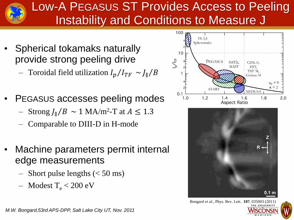
Low-A PEGASUS ST Provides Access to Peeling Instability and Conditions to Measure J
M.W. Bongard,53rd APS-DPP, Salt Lake City UT, Nov. 2011
• Spherical tokamaks naturally provide strong peeling drive
– Toroidal field utilization 𝐼𝑝 𝐼𝑇𝐹 ~ 𝐽∥ 𝐵
• PEGASUS accesses peeling modes
– Strong 𝐽∥ 𝐵 ~ 1 MA/m2-T at 𝐴 ≤ 1.3
– Comparable to DIII-D in H-mode
• Machine parameters permit internal edge measurements
– Short pulse lengths (< 50 ms)
– Modest Te < 200 eV
Bongard et al., Phys. Rev. Lett. 107, 035003 (2011)

PEGASUS: A Mid-Size, Ultralow-A ST
M.W. Bongard,53rd APS-DPP, Salt Lake City UT, Nov. 2011
Experimental Parameters Parameter To Date A
R(m)
Ip (MA)
IN (MA/m-T) ℓi
κ τshot (s)
βt (%) PHHFW (MW)
1.15 – 1.3
0.2 – 0.45
≤ .22
6 – 12 0.2 – 0.5
1.4 – 3.7 ≤ 0.025
≤ 25 0.2
High-stress Ohmic
heating solenoid High-stress Ohmic heating solenoid
RF Heating Antenna
Vacuum Vessel
Equilibrium Field Coils
Toroidal Field Coils
Ohmic Trim Coils 1 m
Plasma Limiters

Radially Scanning Diagnostics Access Edge Region
M.W. Bongard,53rd APS-DPP, Salt Lake City UT, Nov. 2011
• PEGASUS edge region compatible with probes
– Locations variable on
shot-to-shot basis
• External Probes
– Single-point Mirnov,
Langmuir probes
– Toroidal Bz array
• Internal Hall Probe
– Bz(R, t) → J(R, t)

High-Speed Imaging Resolves Detailed Edge Structure
M.W. Bongard,53rd APS-DPP, Salt Lake City UT, Nov. 2011
• IDT MotionPro X4
– 8-bit, 5 kfps framing
– 512x512 resolution
– τexp ~ 5-10 μs
• VRI Phantom Series
– v7.3: 14-bit, < 90–250 kfps framing
– v12.0: 12-bit, < 1 MHz framing
– Variable resolution/frame rates
– τexp ~ 5-10 μs
X4: 40271, 9 μs exposure
Cross-sectional view
Phantom v7.3: 41583, 5 μs exposure
Tangential View
Cross-sectional
Tangential
Viewing Ranges

PEGASUS Hall Probe Deployed to Measure J
M.W. Bongard,53rd APS-DPP, Salt Lake City UT, Nov. 2011
• Solid-state InSb Hall sensors
– Sypris model SH-410
• 16 channels, 7.5 mm radial resolution
• Slim C armor as low-Z PFC
– Minimizes plasma perturbation
• 25 kHz bandwidth
Bongard et al., Rev. Sci. Instrum. 81, 10E105 (2010)

Solid-state Hall Sensors Sample B Directly
M.W. Bongard,53rd APS-DPP, Salt Lake City UT, Nov. 2011
• Provides VH = GH Ic B
– GH combines all Hall physics
effects; determined by calibration
– Simple operation with constant
control current Ic ~ mA
• High spatial, good temporal resolution
– Sensor size: few mm
– Bandwidth ~ 25 kHz
• Weak variance in GH possible
– Hall semiconductor, Tsensor, B||
– Calibration corrects these effects
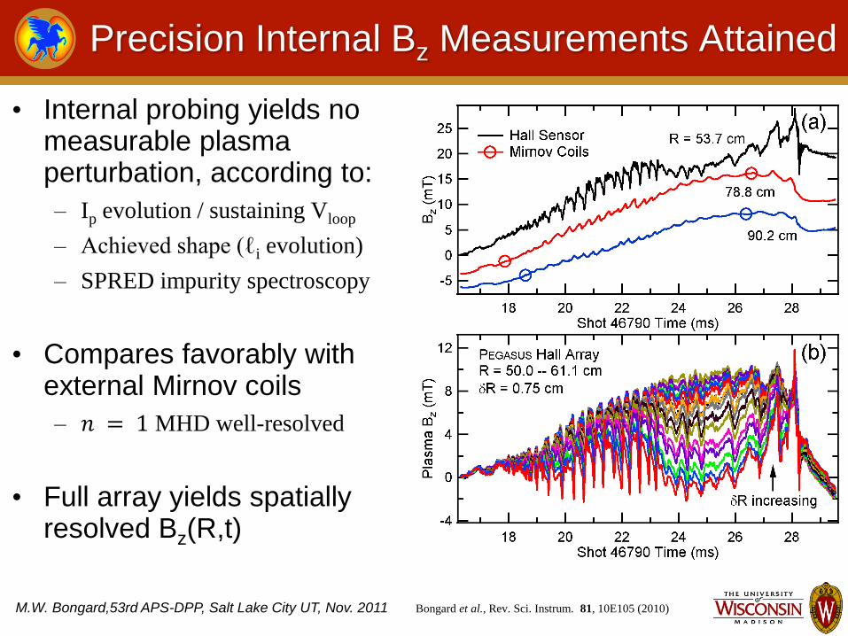
Precision Internal Bz Measurements Attained
M.W. Bongard,53rd APS-DPP, Salt Lake City UT, Nov. 2011
• Internal probing yields no measurable plasma perturbation, according to:
– Ip evolution / sustaining Vloop
– Achieved shape (ℓi evolution)
– SPRED impurity spectroscopy
• Compares favorably with external Mirnov coils
– 𝑛 = 1 MHD well-resolved
• Full array yields spatially resolved Bz(R,t)
Bongard et al., Rev. Sci. Instrum. 81, 10E105 (2010)
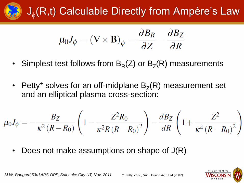
J(R,t) Calculable Directly from Ampère’s Law
M.W. Bongard,53rd APS-DPP, Salt Lake City UT, Nov. 2011
• Simplest test follows from BR(Z) or BZ(R) measurements
• Petty* solves for an off-midplane BZ(R) measurement set and an elliptical plasma cross-section:
• Does not make assumptions on shape of J(R)
*: Petty, et al., Nucl. Fusion 42, 1124 (2002)

Direct J(R) Profiles Obtained in PEGASUS
M.W. Bongard,53rd APS-DPP, Salt Lake City UT, Nov. 2011 *: Reinsch, Numerische Mathematik 10, 177 (1967)
Bongard et al., Phys. Rev. Lett. 107, 035003 (2011)
• Straightforward J estimation
– Obtain Hall Probe Bz(R,t)
– Compute dBZ/dR using
interpolated smoothing spline*
– Compute J(R,t) given geometry
• Resultant J(R,t) consistent with Ip, MHD evolution
• Radial span extendible with multi-shot averaging
• Higher-order shaping effects negligible within errors
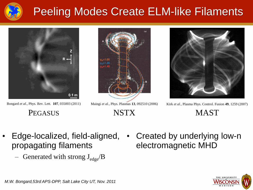
Peeling Modes Create ELM-like Filaments
M.W. Bongard,53rd APS-DPP, Salt Lake City UT, Nov. 2011
• Edge-localized, field-aligned, propagating filaments
– Generated with strong Jedge/B
• Created by underlying low-n electromagnetic MHD
Maingi et al., Phys. Plasmas 13, 092510 (2006)
NSTX
MAST
Kirk et al., Plasma Phys. Control. Fusion 49, 1259 (2007)
36116
PEGASUS
Bongard et al., Phys. Rev. Lett. 107, 035003 (2011)

Two Distinct Filament Classes Observable
M.W. Bongard,53rd APS-DPP, Salt Lake City UT, Nov. 2011
• Peeling (a)
– EM signature: high m, low n
– Coherent spatial structure
– Filament rotation
– Detachment, outboard radial
propagation, acceleration
• MHD Quiescent / L-mode (b)
– No EM signature
– Electrostatic turbulence: short-
lived filaments observable when
τexp ≤ 20 μs
– No detachment, propagation
MHD Quiescent (b) Peeling (a)
11 μs τexp, visible λ

Peeling Filaments Are Coherent Global Structures
M.W. Bongard,53rd APS-DPP, Salt Lake City UT, Nov. 2011
• High poloidal coherence
– Simultaneous growth, decay of high-m structures
• Short lifetime: ~ 55 μs
– Resolvable with exposure times ≤ 30 μs
– Larger exposures → conventional L-mode fuzzy edge
• Detachment, radial propagation
Average
0-9 μs 11-20 μs 22-31 μs 33-42 μs 44-53 μs
41591

Peeling Filaments Have Electromagnetic Origin
M.W. Bongard,53rd APS-DPP, Salt Lake City UT, Nov. 2011
• Magnetic, Langmuir probes placed at plasma edge
• Peeling modes produce coherent electromagnetic activity
– Uncorrelated with
electrostatic LP fluctuations
• No EM signature in MHD quiescent phase
– Consistent with electrostatic
L-mode turbulence

Peeling MHD Only Detectable Near Edge
M.W. Bongard,53rd APS-DPP, Salt Lake City UT, Nov. 2011
• Radial scan of magnetic probe array profiled spatial dependence of peeling MHD
• Dominant 20 kHz spectral peak vanishes rapidly from edge
• Signature undetectable on Mirnov coils near R ~ 90 cm
• Implies underlying activity has high poloidal mode number m

Spectral Analysis Finds Low-n, High-m MHD
M.W. Bongard,53rd APS-DPP, Salt Lake City UT, Nov. 2011
• Dominant cross-power Fourier component used for mode identification
• Toroidal cross-phase analysis finds n = 2
• Lab-space poloidal mode estimation (cylindrical limit)
– Poloidal cross-phase: mlab ≈ 41
– P8 Radial decay rate: mlab ≈ 42
• Accurate m estimation requires straight field line coordinate transformation

Reconstructions Spatially Localize MHD to Edge
M.W. Bongard,53rd APS-DPP, Salt Lake City UT, Nov. 2011
• Equilibrium reconstruction performed to localize peeling resonant q surface
– 𝐼𝑊𝐴𝐿𝐿 𝐼𝑝 = 1.9
• Cylindrical mode analysis found dominant mlab / n = 20.5
• This q surface clearly lies in the edge region
– 𝑞 = 20.5 at 𝜓𝑁 = 0.98

Straight Field Line Transform Further Localizes MHD
• PEST SFL coordinates* can convert mlab to the plasma frame
– 𝑚 = 𝑓 𝑞 𝑚𝑙𝑎𝑏; 𝑓(𝑞) ~ 3–7 here
– θ overestimates Θ at outboard midplane,
implying mlab ≤ m
• Application places true resonance at or exterior to edge
– Consistent with peeling mode external kink
structure *: D’haeseleer, et al., Flux Coordinates
and Magnetic Field Structure, 1991

Experiment Tests MHD Dependence on J/B Drive
M.W. Bongard,53rd APS-DPP, Salt Lake City UT, Nov. 2011
• Peeling drive varied systematically in Ip ramp
– Shape well-matched
• Experimental proxies:
– dIp/dt ~ Jedge; ITF ~ B
– 11 combinations dIp/dt, ITF
• Uniform edge diagnosis
– Hall, edge magnetic probes
– 27 kHz fast imaging
• Equilibrium reconstructions
– Spatial localization of MHD Phantom Imaging:
Original; 270 μs average subtracted
48206 10 us

Edge Current Profile Manipulated with dIp/dt
M.W. Bongard,53rd APS-DPP, Salt Lake City UT, Nov. 2011
• Direct Hall analysis used to obtain J(R) in scan discharges
• J||/B estimated from experiment by ΔJ/B
– Linear trend in edge current
gradient ΔJ/ B
– Increasing ΔJ
– Reduced gradient scale length
• Trends independent of B

Peeling MHD Strongly Scales with Theoretical Drive
M.W. Bongard,53rd APS-DPP, Salt Lake City UT, Nov. 2011
• Mode helicities estimated from port 8 Mirnov array
– n < 3 via cross-phase analysis
– mlab ≥ 10 via radial decay rate
– 10 ≤ mlab / n ≤ 30 (𝜓𝑁 > 0.9)
• MHD power spans two orders of magnitude with factor-of-five variation in J/B
Bongard et al., Phys. Rev. Lett. 107, 035003 (2011)

Hall-Constrained Equilibrium Obtained During Peeling Activity
M.W. Bongard,53rd APS-DPP, Salt Lake City UT, Nov. 2011
• High-performance discharge with peeling activity
• 𝐽𝜙 𝜓 determined by
reconstruction with Hall data
– 𝜓𝑁 > 0.5 constrained
– 𝐽𝜙 ~ 500 kA/m2 in edge
• New KFIT tools applied
– Akima spline parametrization
– Fine-spaced 256x256 grid
– δR= 3.3 mm, δZ = 6.72 mm
– 𝐼𝑊𝐴𝐿𝐿 𝐼𝑝 = 1.1

Reconstructed BZ(R) Reasonably Matches Hall Data
M.W. Bongard,53rd APS-DPP, Salt Lake City UT, Nov. 2011
• Good agreement internal, external to plasma boundary
• Disagreement in vicinity near R = 0.565 m equates to region 0.95 < 𝜓𝑁 ≤ 1

Stability Analysis Confirms Peeling Instability
M.W. Bongard,53rd APS-DPP, Salt Lake City UT, Nov. 2011
• Analytic peeling criterion computed from Hall-constrained equilibrium indicates instability
– More than factor of two in region
of optimal 𝐽𝜙 constraint
• Free-boundary ideal stability analysis performed with DCON
– Indicates instability to m/n = 19/1
external kink
• Both methods agree with experiment
Bongard et al., Phys. Rev. Lett. 107, 035003 (2011)

Synthetic Diagnostic Tests Direct J Method
M.W. Bongard,53rd APS-DPP, Salt Lake City UT, Nov. 2011
• Hall equilibrium used to test direct, reconstructed J(R)
– Direct method applied to
synthetic BZ(R) fit by KFIT
• Direct, synthetic J(R) profiles agree within error
– Reconstructed J(R) disagrees
with direct in vicinity of LCFS
• Slight open field line currents indicated
– ~ 100 A; < 0.1% of Ip
– KFIT profile parametrizations
cannot place J outside LCFS

Jedge Dynamics Measured on ELM Timescales
M.W. Bongard,53rd APS-DPP, Salt Lake City UT, Nov. 2011 Bongard et al., Phys. Rev. Lett. 107, 035003 (2011)
• Jedge resolved during peeling filament generation
• Propagating filament forms from initial “current-hole” Jedge perturbation
– Validates formation mechanism
hypothesized by EM blob transport
theory
• Filament carries toroidal current If ~ 100–220 A
– Comparable to MAST ELM estimates
– If < 0.2 % of Ip
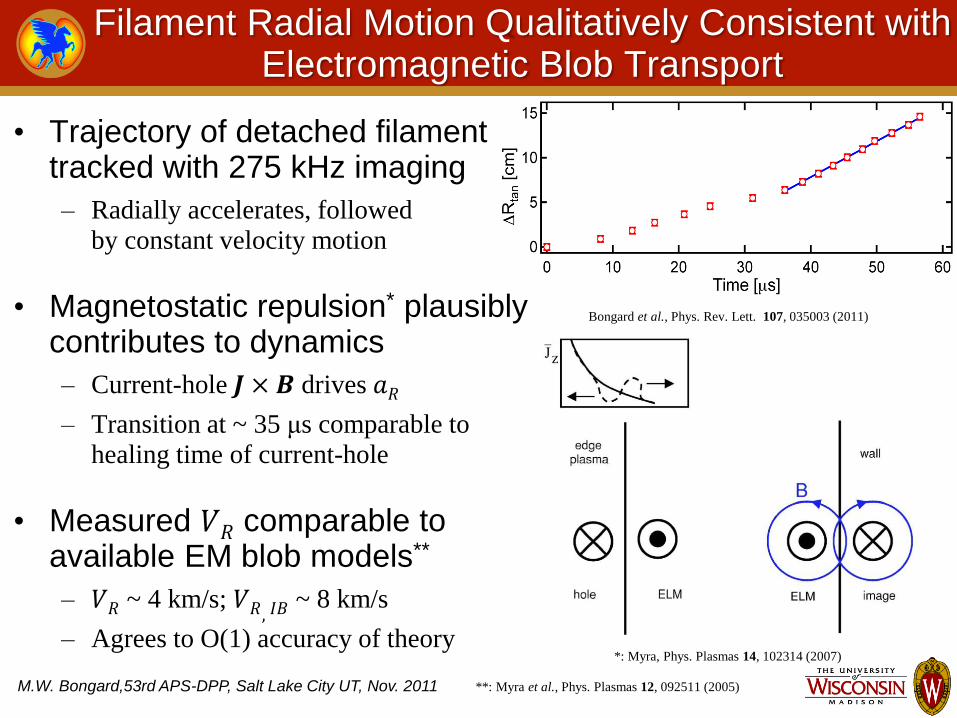
Filament Radial Motion Qualitatively Consistent with Electromagnetic Blob Transport
M.W. Bongard,53rd APS-DPP, Salt Lake City UT, Nov. 2011
Bongard et al., Phys. Rev. Lett. 107, 035003 (2011)
*: Myra, Phys. Plasmas 14, 102314 (2007)
• Trajectory of detached filament tracked with 275 kHz imaging
– Radially accelerates, followed
by constant velocity motion
• Magnetostatic repulsion* plausibly contributes to dynamics
– Current-hole 𝑱 × 𝑩 drives 𝑎𝑅
– Transition at ~ 35 μs comparable to
healing time of current-hole
• Measured 𝑉𝑅 comparable to available EM blob models**
– 𝑉𝑅 ~ 4 km/s; 𝑉𝑅, 𝐼𝐵 ~ 8 km/s
– Agrees to O(1) accuracy of theory
**: Myra et al., Phys. Plasmas 12, 092511 (2005)

Conclusions
M.W. Bongard,53rd APS-DPP, Salt Lake City UT, Nov. 2011
• Direct measurements of Jedge conducted with Hall probe
– Direct analysis, equilibrium reconstruction
– Jedge controllable with dIp/dt
• Characteristics of peeling modes consistent with theory
– Macroscopic features: Low-n, high-m external kink
– Onset consistent with ideal MHD, analytic peeling stability theories
– Observed MHD scales with measured J/B peeling drive
– Coherent, propagating filaments
• Jedge dynamics supports current-hole & EM blob hypotheses
– Nonlinear filaments generated from current-hole Jedge perturbation
– Transient magnetostatic repulsion
– Constant-VR propagation in agreement with available EM blob theory

Reprints
M.W. Bongard,53rd APS-DPP, Salt Lake City UT, Nov. 2011
Reprints of this and other PEGASUS presentations are available online at
http://pegasus.ep.wisc.edu/Technical_Reports