Embed Size (px)
Citation preview
1
Peeking Into Second Life – A JT-Linden Scripting Language Translator
Hemant RamaswamiRatnadeep Paul
Shreenivasan ManievannanSam Anand ([email protected])
University of Cincinnati
2Computer-Aided Manufacturing Laboratory
About Us
UC Engineering established in 1900
CAM Laboratory established in 1990Director: Dr. Sam Anand
2 Doctoral, 5 Masters, 7 Undergraduate Students
Research AreasCAD, PLM, Engineering Design and Design for Manufacturing
Optimization Methods in Manufacturing
Precision Engineering and Computational Metrology
Automation, Factory Flow Analysis and Lean Methods
3Computer-Aided Manufacturing Laboratory 3
Outline
SL – A Brief Introduction
JT File Format and JT Toolkit
Background and Motivation
Methodology
How to use the translator
Results
Future work
4Computer-Aided Manufacturing Laboratory
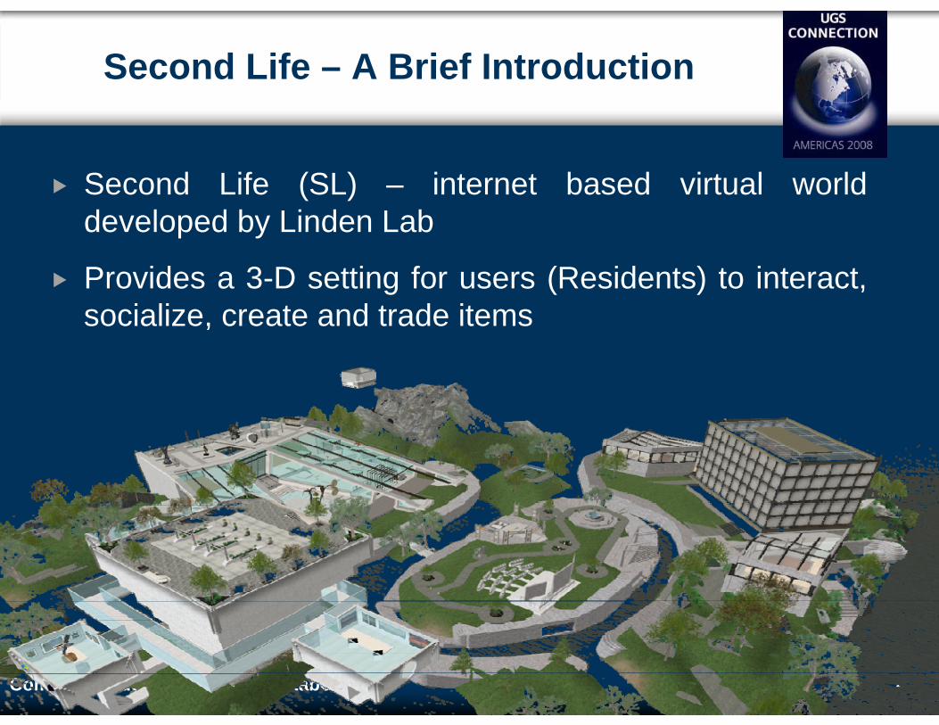
Second Life – A Brief Introduction
Second Life (SL) – internet based virtual world developed by Linden Lab
Provides a 3-D setting for users (Residents) to interact, socialize, create and trade items
5Computer-Aided Manufacturing Laboratory
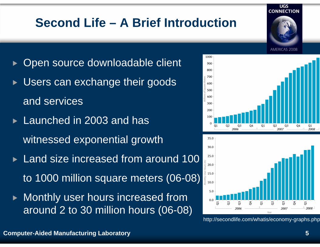
Second Life – A Brief Introduction
Open source downloadable client
Users can exchange their goods
and services
Launched in 2003 and has
witnessed exponential growth
Land size increased from around 100
to 1000 million square meters (06-08)
Monthly user hours increased from around 2 to 30 million hours (06-08)
http://secondlife.com/whatis/economy-graphs.php
6Computer-Aided Manufacturing Laboratory
Second Life – Terms Explained
Avatar – Virtual persona of the user in SL
In-World – In the Second Life virtual world
Linden Dollars – Virtual currency in SL
Sim – SL Simulator
Prims – Basic building blocks in SL
LSL – Linden Scripting Language, internal, event-driven, C/Java-style language
Scripts – LSL codes acting upon prims or avatars
Rez – Creating objects in SL
Inventory – Collection of objects stored by an object or user
7Computer-Aided Manufacturing Laboratory
JT File Format and JT Toolkit
JT File Format
Lightweight yet robust CAD neutral file format
Widespread in automotive and aerospace industries
Visualization, Collaboration and Data Sharing
JT Open Toolkit
C++ library API functions to read and write JT files
CAD models can be written into JT files for later use or exchange
8Computer-Aided Manufacturing Laboratory
Background and Motivation
JT technology facilitates exchange of 3D data for
visualization, collaboration and data-sharing
Second Life (SL) provides a platform for
collaboration and sharing of data and information
Growing demand for visualization and modeling in
SL and for easy interfacing between conventional
solid modeling software and SL
9Computer-Aided Manufacturing Laboratory
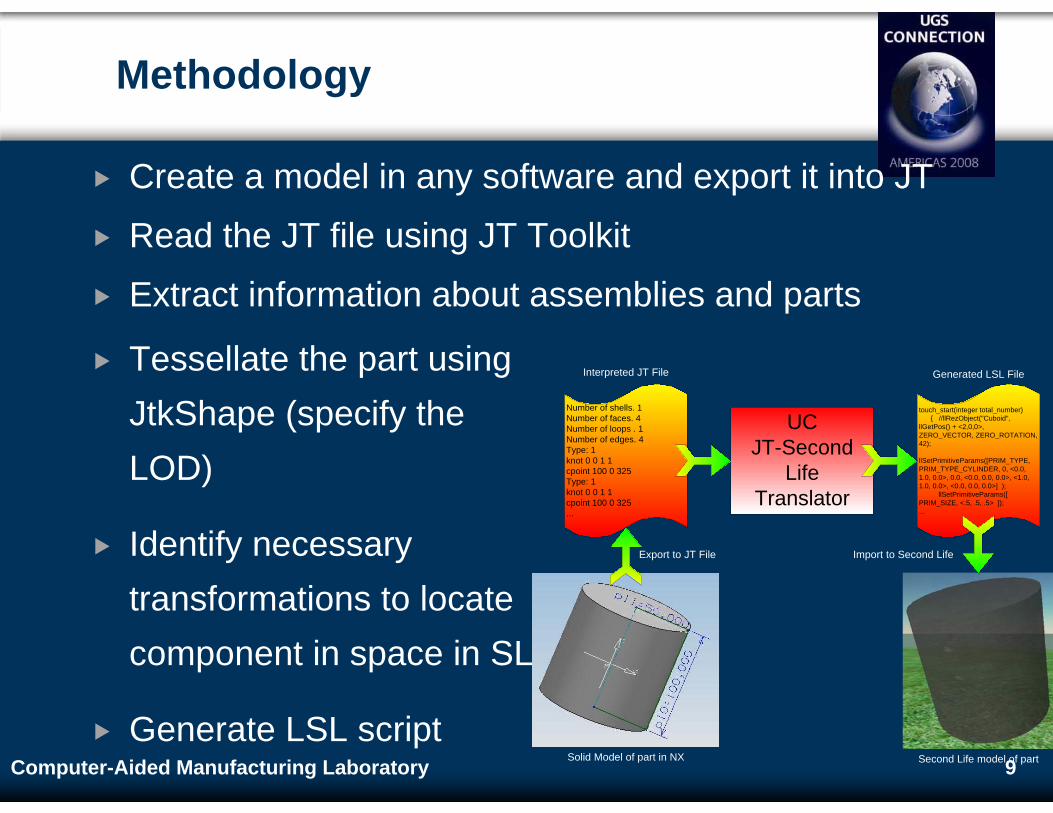
Create a model in any software and export it into JT
Read the JT file using JT Toolkit
Extract information about assemblies and parts
Tessellate the part using JtkShape (specify the LOD)
Identify necessary transformations to locate component in space in SL
Generate LSL script
Methodology
Solid Model of part in NX Second Life model of part
Number of shells. 1Number of faces. 4Number of loops . 1Number of edges. 4Type: 1knot 0 0 1 1cpoint 100 0 325Type: 1knot 0 0 1 1cpoint 100 0 325...
touch_start(integer total_number) { //llRezObject("Cuboid", llGetPos() + <2,0,0>, ZERO_VECTOR, ZERO_ROTATION, 42);
llSetPrimitiveParams([PRIM_TYPE, PRIM_TYPE_CYLINDER, 0, <0.0, 1.0, 0.0>, 0.0, <0.0, 0.0, 0.0>, <1.0, 1.0, 0.0>, <0.0, 0.0, 0.0>] ); llSetPrimitiveParams([ PRIM_SIZE, <.5, .5, .5> ]);...
UCJT-Second
LifeTranslator
Interpreted JT File Generated LSL File
Export to JT File Import to Second Life
10Computer-Aided Manufacturing Laboratory
Methodology
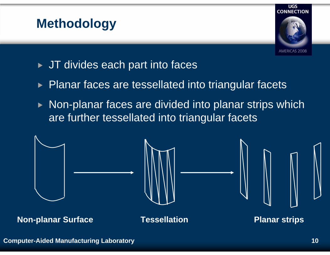
JT divides each part into faces
Planar faces are tessellated into triangular facets
Non-planar faces are divided into planar strips which are further tessellated into triangular facets
TessellationNon-planar Surface Planar strips
11Computer-Aided Manufacturing Laboratory
Methodology
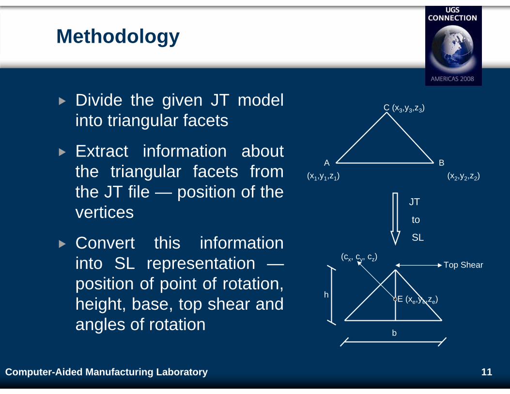
Divide the given JT model into triangular facets
Extract information about the triangular facets from the JT file — position of the vertices
Convert this information into SL representation —position of point of rotation, height, base, top shear and angles of rotation
A B
C
(x1,y1,z1) (x2,y2,z2)
(x3,y3,z3)
JT
to
SL
b
h E (xe,ye,ze)
Top Shear(cx, cy, cz)
12Computer-Aided Manufacturing Laboratory
Representation of Triangular Facets in SL
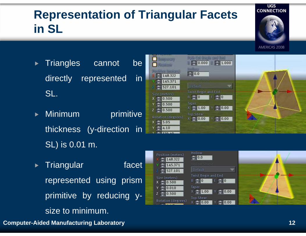
Triangles cannot be
directly represented in
SL.
Minimum primitive
thickness (y-direction in
SL) is 0.01 m.
Triangular facet
represented using prism
primitive by reducing y-
size to minimum.
13Computer-Aided Manufacturing Laboratory
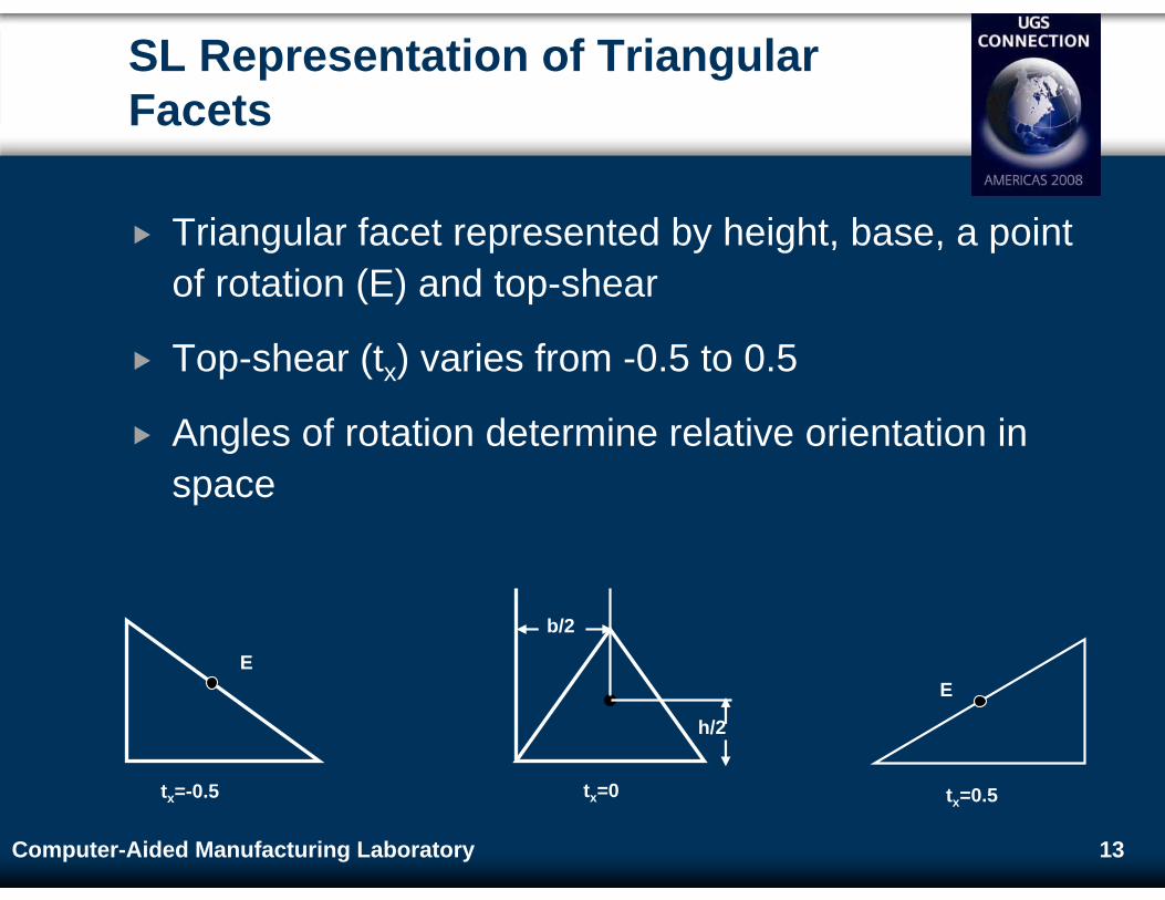
SL Representation of Triangular Facets
Triangular facet represented by height, base, a point of rotation (E) and top-shear
Top-shear (tx) varies from -0.5 to 0.5
Angles of rotation determine relative orientation in space
tx=-0.5
E
tx=0
b/2
h/2
tx=0.5
E
14Computer-Aided Manufacturing Laboratory
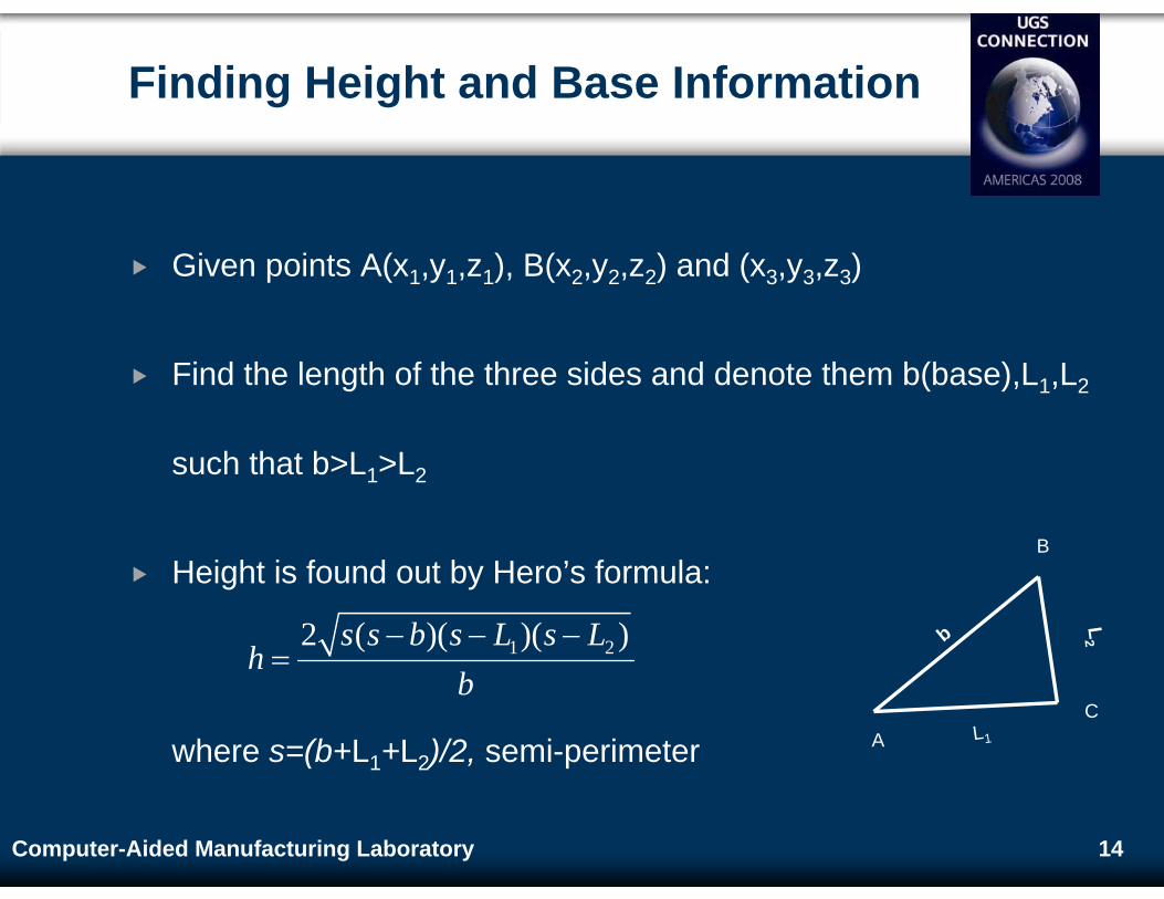
Finding Height and Base Information
Given points A(x1,y1,z1), B(x2,y2,z2) and (x3,y3,z3)
Find the length of the three sides and denote them b(base),L1,L2
such that b>L1>L2
Height is found out by Hero’s formula:
where s=(b+L1+L2)/2, semi-perimeter
b
L2
L1A
B
C
1 22 ( )( )( )s s b s L s Lh
b− − −
=
15Computer-Aided Manufacturing Laboratory
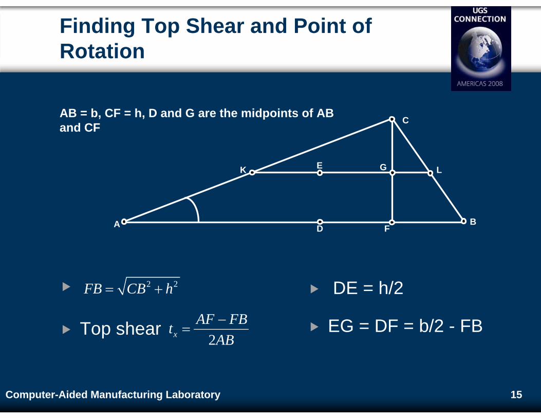
Finding Top Shear and Point of Rotation
C
A D FB
K E LG
AB = b, CF = h, D and G are the midpoints of AB and CF
Top shear
2 2FB CB h= +
2xAF FBt
AB−
=
DE = h/2
EG = DF = b/2 - FB
16Computer-Aided Manufacturing Laboratory
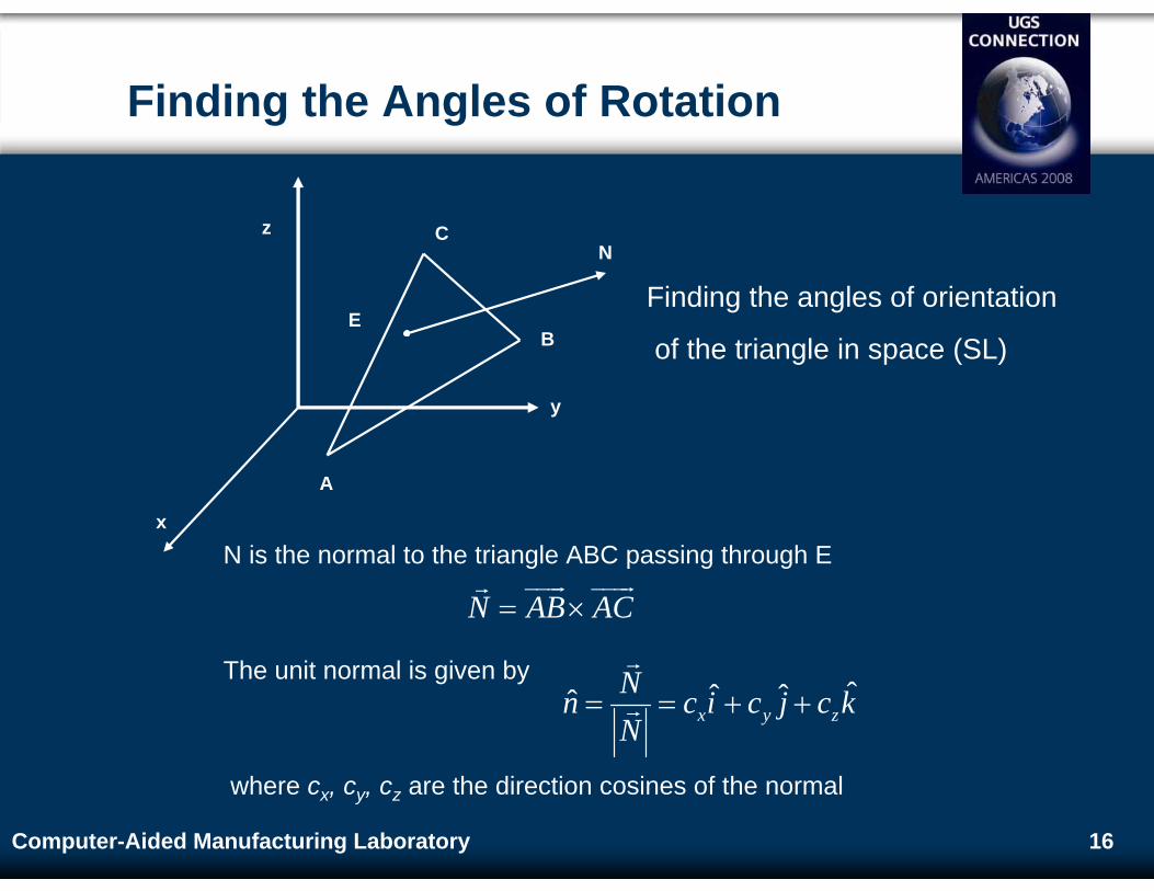
Finding the Angles of Rotation
Finding the angles of orientation
of the triangle in space (SL)
A
C
B
x
z
y
E
N
N is the normal to the triangle ABC passing through E
The unit normal is given by
where cx, cy, cz are the direction cosines of the normal
ˆˆ ˆˆ x y zNn c i c j c kN
= = + +
N AB AC= ×
17Computer-Aided Manufacturing Laboratory
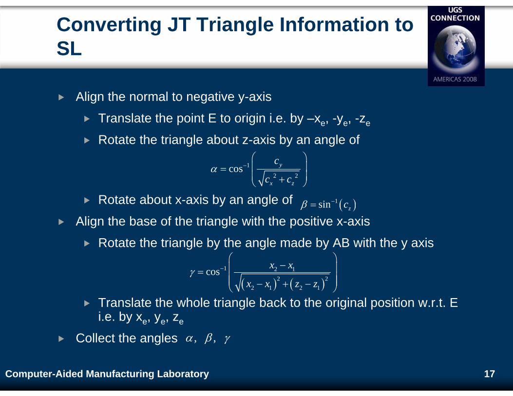
Converting JT Triangle Information to SL
Align the normal to negative y-axis
Translate the point E to origin i.e. by –xe, -ye, -ze
Rotate the triangle about z-axis by an angle of
Rotate about x-axis by an angle of
Align the base of the triangle with the positive x-axis
Rotate the triangle by the angle made by AB with the y axis
Translate the whole triangle back to the original position w.r.t. E i.e. by xe, ye, ze
Collect the angles
1
2 2cos y
x z
c
c cα −
⎛ ⎞⎜ ⎟=⎜ ⎟+⎝ ⎠
( )1sin zcβ −=
, ,α β γ
( ) ( )1 2 1
2 22 1 2 1
cos x x
x x z zγ −
⎛ ⎞−⎜ ⎟=
⎜ ⎟⎜ ⎟− + −⎝ ⎠
18Computer-Aided Manufacturing Laboratory
Rotation in SL
Order of rotation in SL will be:
First an angle of γ about y-axis
By an angle of β about x-axis
An angle of α about z-axis
Rotation in SL is done in terms of quaternions
Quaternions are helpful when there are successive rotations involved
19Computer-Aided Manufacturing Laboratory
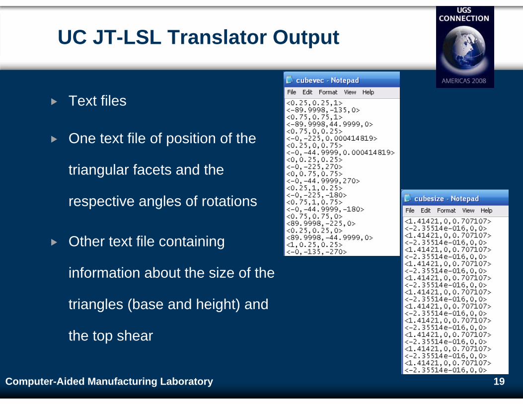
UC JT-LSL Translator Output
Text files
One text file of position of the
triangular facets and the
respective angles of rotations
Other text file containing
information about the size of the
triangles (base and height) and
the top shear
20Computer-Aided Manufacturing Laboratory
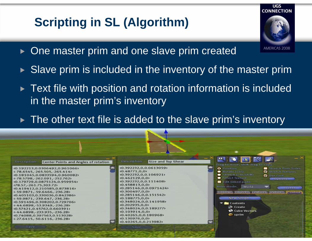
Scripting in SL (Algorithm)
One master prim and one slave prim created
Slave prim is included in the inventory of the master prim
Text file with position and rotation information is included in the master prim’s inventory
The other text file is added to the slave prim’s inventory
21Computer-Aided Manufacturing Laboratory
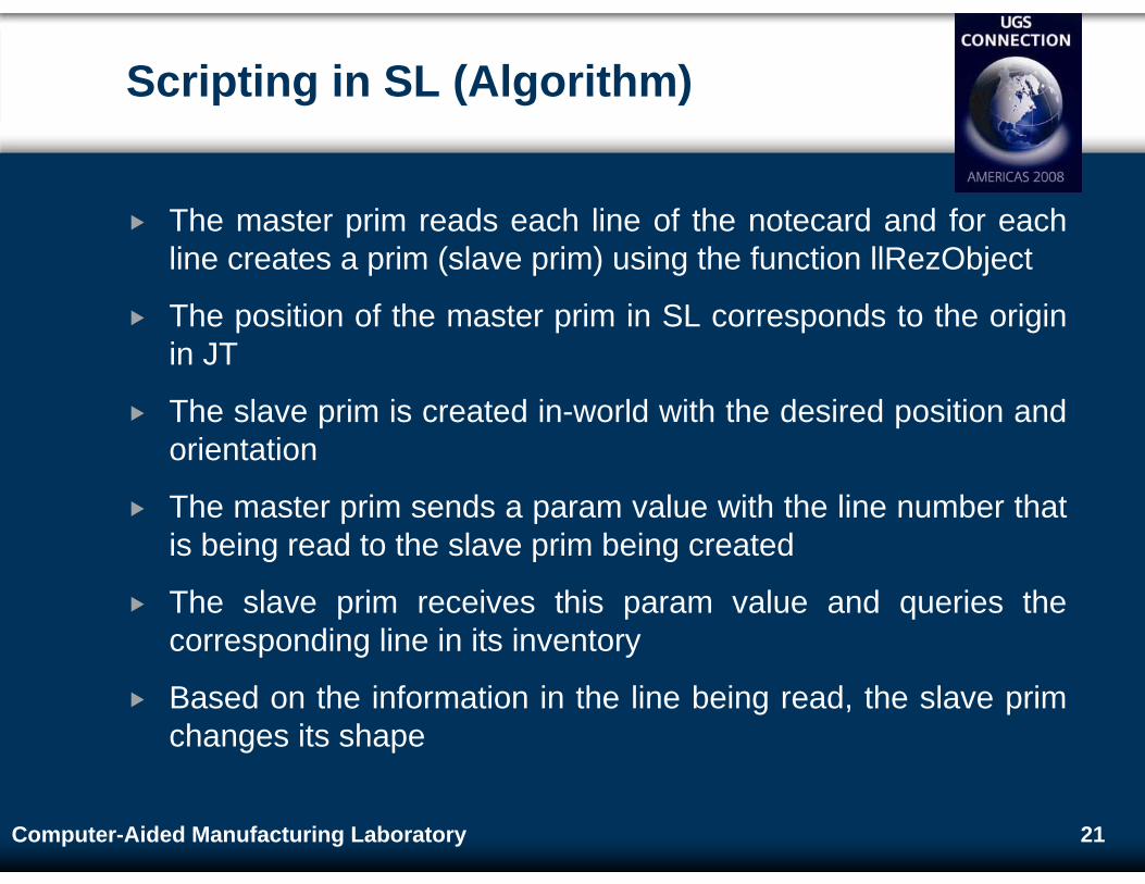
Scripting in SL (Algorithm)
The master prim reads each line of the notecard and for each line creates a prim (slave prim) using the function llRezObject
The position of the master prim in SL corresponds to the origin in JT
The slave prim is created in-world with the desired position and orientation
The master prim sends a param value with the line number that is being read to the slave prim being created
The slave prim receives this param value and queries the corresponding line in its inventory
Based on the information in the line being read, the slave prim changes its shape
22Computer-Aided Manufacturing Laboratory
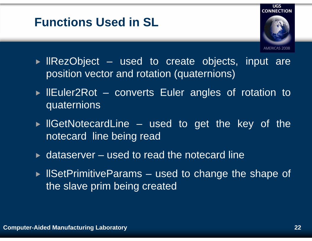
Functions Used in SL
llRezObject – used to create objects, input are position vector and rotation (quaternions)
llEuler2Rot – converts Euler angles of rotation to quaternions
llGetNotecardLine – used to get the key of the notecard line being read
dataserver – used to read the notecard line
llSetPrimitiveParams – used to change the shape of the slave prim being created
23Computer-Aided Manufacturing Laboratory
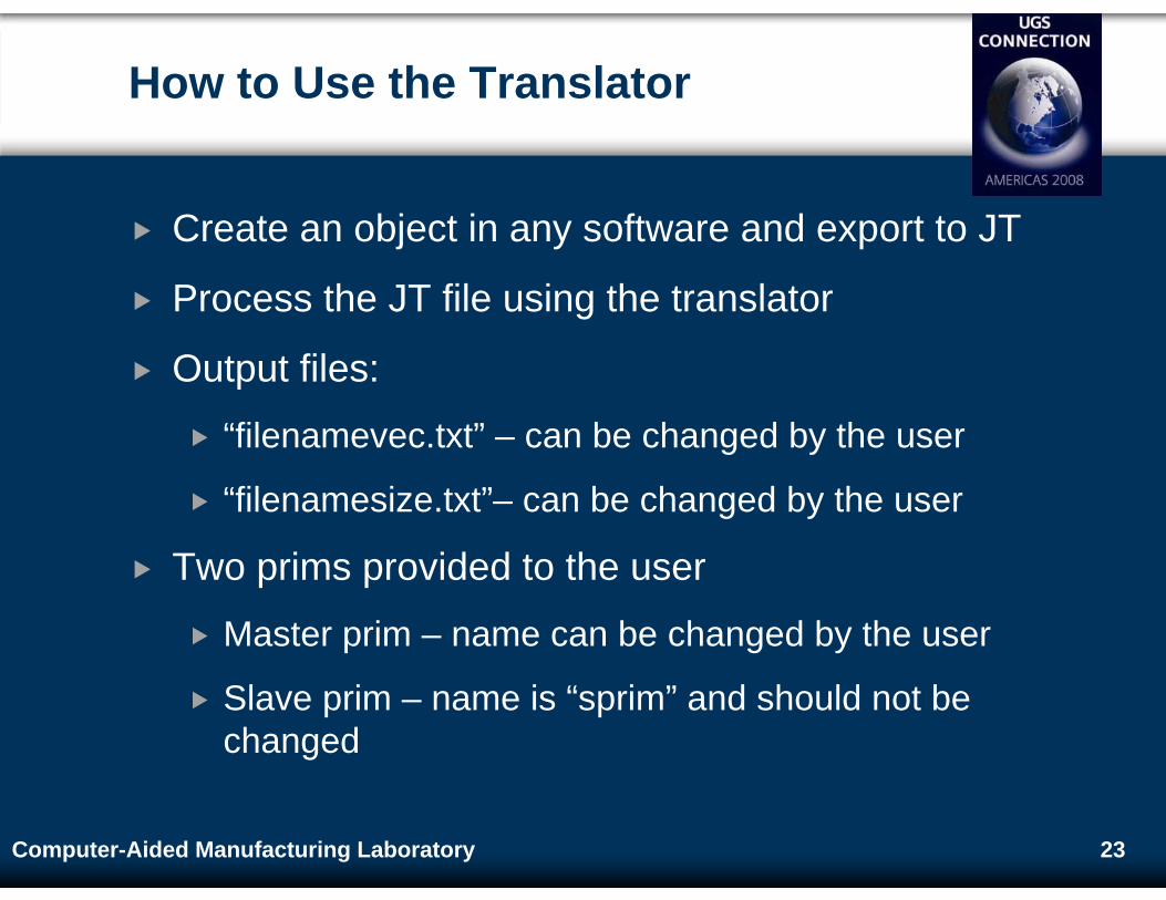
How to Use the Translator
Create an object in any software and export to JT
Process the JT file using the translator
Output files:
“filenamevec.txt” – can be changed by the user
“filenamesize.txt”– can be changed by the user
Two prims provided to the user
Master prim – name can be changed by the user
Slave prim – name is “sprim” and should not be changed
24Computer-Aided Manufacturing Laboratory
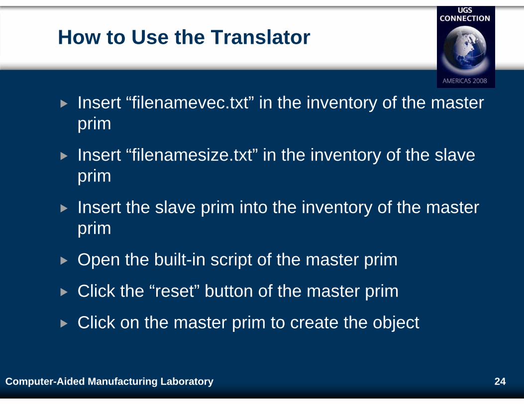
How to Use the Translator
Insert “filenamevec.txt” in the inventory of the master prim
Insert “filenamesize.txt” in the inventory of the slave prim
Insert the slave prim into the inventory of the master prim
Open the built-in script of the master prim
Click the “reset” button of the master prim
Click on the master prim to create the object
25Computer-Aided Manufacturing Laboratory
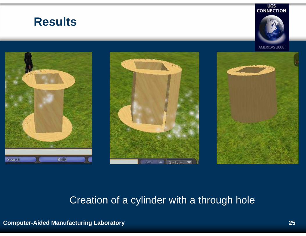
Results
Creation of a cylinder with a through hole
26Computer-Aided Manufacturing Laboratory
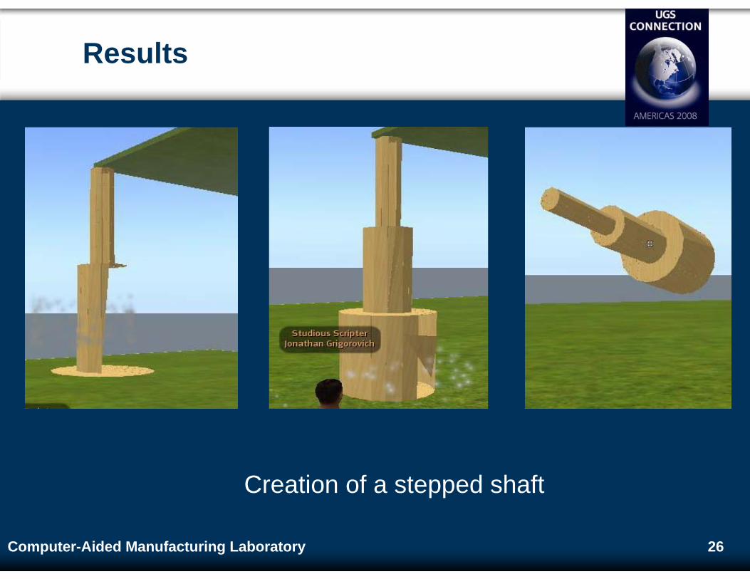
Results
Creation of a stepped shaft
27Computer-Aided Manufacturing Laboratory
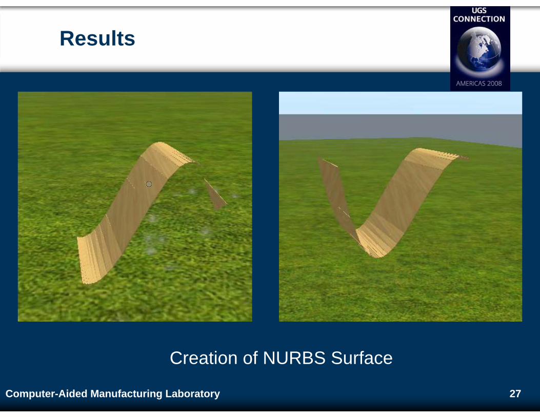
Results
Creation of NURBS Surface
28Computer-Aided Manufacturing Laboratory
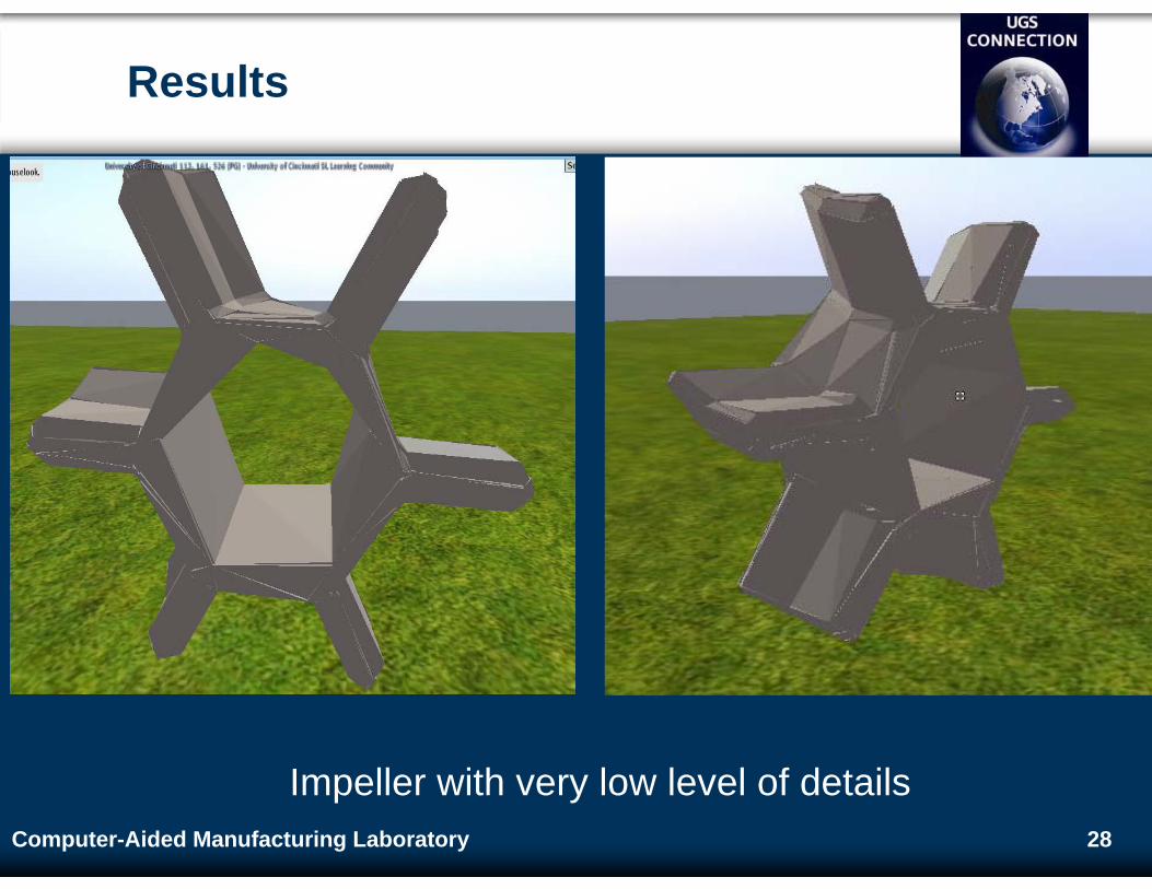
Results
Impeller with very low level of details
29Computer-Aided Manufacturing Laboratory
Future Work
Prim Optimization
Use of quad elements instead of triangles
Max reduction of prims by a factor of 0.5
Use of box or prism elements (3-D) instead of triangles
Incorporate texture information
Use of sculpted prims
Image based rendering
With development of SL capabilities, use of B-Rep information can also be used
30
Thank You