Embed Size (px)
Citation preview
Noname manuscript No.(will be inserted by the editor)
Pedicle Screw Navigation using Surface Digitization on theMicrosoft HoloLens
Florentin Liebmann1,2 · Simon Roner1,3 · Marcovon Atzigen1 · Davide Scaramuzza4,5 · RetoSutter6 · Jess Snedeker2,3 · Mazda Farshad3 ·Philipp Furnstahl1
1Computer Assisted Research and DevelopmentGroup, Balgrist University Hospital, University of Zurich, Zurich,Switzerland2Laboratory for Orthopaedic Biomechanics, ETH Zurich, Zurich,Switzerland3Orthopaedic Department, Balgrist University Hospital, Universityof Zurich, Zurich, Switzerland4Department of Informatics, University of Zurich, Zurich,Switzerland5Department of Neuroinformatics, University of Zurich and ETHZurich, Zurich, Switzerland6Radiology Department, Balgrist University Hospital, Universityof Zurich, Zurich, Switzerland
Received: date / Accepted: date
AbstractPurpose: In spinal fusion surgery, imprecise placement of pedicle screws can result in poorsurgical outcome or may seriously harm a patient. Patient-specific instruments and opticalsystem have been proposed for improving precision through surgical navigation comparedto free-hand insertion. However, existing solutions are expensive and cannot provide in situvisualizations. Recent technological advancement enabled the production of more powerfuland precise optical see-through head-mounted displays for the mass market. The purposeof this laboratory study was to evaluate whether such a device is sufficiently precise for thenavigation of lumbar pedicle screw placement.Methods: A novel navigation method, tailored to run on the Microsoft HoloLens, was devel-oped. It comprises capturing of the intraoperatively reachable surface of vertebrae to achieveregistration and tool tracking with real-time visualizations without the need of intraoperativeimaging. For both, surface sampling and navigation, 3D printable parts, equipped with fidu-cial markers, were employed. Accuracy was evaluated within a self-built setup based on twophantoms of the lumbar spine. Computed Tomography (CT) scans of the phantoms wereacquired to carry out preoperative planning of screw trajectories in 3D. A surgeon placed
Florentin LiebmannBalgrist University HospitalForchstrasse 3408008 ZurichSwitzerlandTel.: +41 44 510 73 59E-mail: [email protected]
2 Florentin Liebmann1,2 et al.
the guiding wire for the pedicle screw bilaterally on ten vertebrae guided by the navigationmethod. Postoperative CT scans were acquired to compare trajectory orientation (3D angle)and screw insertion points (3D distance) with respect to the planning.Results: The mean errors between planned and executed screw insertion were 3.38±1.73◦
for the screw trajectory orientation and 2.77±1.46 mm for the insertion points. The meantime required for surface digitization was 125±27 s.Conclusions: First promising results under laboratory conditions indicate that precise lum-bar pedicle screw insertion can be achieved by combining HoloLens with our proposednavigation method. As a next step, cadaver experiments need to be performed to confirm theprecision on real patient anatomy.
Keywords Surgical navigation · Augmented reality · Surface digitization · HoloLens ·Spine · Pedicle screw
1 Introduction
Spine disorders are among the most frequent musculoskeletal pathologies in developedcountries [1]. They cause diminished quality-of-life to the patients and result in substan-tial socio-economical costs [2]. Most patients can be treated successfully in a conservativeway by initial physical protection, pain medication and back training [3]. However, surgeryis indicated in patients with more severe conditions such as degenerative disc disease, frac-ture treatment, and scoliosis. In such pathologies, spinal fusion has been established as thebenchmark surgical treatment [4–6].
In the state-of-the-art surgical treatment an open surgery is performed, in which thevertebrae of the pathological segment are fused with an orthopaedic implant. Pedicle screwsare drilled into each vertebra and connected with the implant to achieve a rigid connection ofthe bone-implant interface. Screw insertion relies on the preparation of guiding holes witha surgical awl or by drilling K-wires. The surgeon aims for a central position of the guidinghole within the pedicle by using bony landmarks as an orientation help. Deviation from theoptimal position can result in pedicle screw penetration which in turn can lead to seriousinjury of the spinal cord, nerve roots, and major vessels.
Unfortunately, accuracy of placement of pedicle screws is low with 68% with use of thestandard method by aid of conventional fluoroscopy [7]. In more challenging scenarios, suchas instrumentation of neuromuscular scoliosis, the accuracy is even less, particularly in theupper thoracic region [8]. 3D printing techniques have been proposed to increase accuracy[9, 10]. However, manufacturing is time consuming and expensive. Furthermore, the lackof intraoperative flexibility is considered to be disadvantageous. More popular navigationapproaches are based on imaging. 2D and 3D fluoroscopic navigation can increase accuracyto 84% and 96%, respectively [7]. Wile 2D/3D fluoroscopy provide surgical navigation ina passive way, intraoperative CT can be used in combination with high-end optical or evenrobotic navigation systems [11] to enable real-time tool and screw localization. However, theincreased use of fluoroscopy or CT exposes the patient to a significant amount of radiation[12–15].
Several methods have been proposed to avoid the use of intraoperative imaging. In in-traoperative manual surface digitization approaches, part of the intraoperative bone anatomyis acquired by optically-tracked pointing devices [16–18]. The so acquired bone surface canbe registered to the preoperative planning using surface registration algorithms [16]. Com-bined with tool tracking, these methods can provide real-time surgical navigation displayed
Pedicle Screw Navigation using Surface Digitization on the Microsoft HoloLens 3
on wall- or rack-mounted 2D monitors [19]. Despite the interesting and easy to use registra-tion approach, these systems are prone to occlusion problems because they cannot providein situ image acquisition and visualization [20]. In addition, they come along with high costsfor acquisition and maintenance.
A simpler and cheaper system to increase precision of pedicle screw placement would befavorable. One solution could be the application of augmented reality (AR). AR technologyis capable of superimposing a preoperative planning with the intraoperative anatomy suchthat surgical navigation can be provided directly in the line of sight of a surgeon. In the med-ical context, AR aroused interest already several decades ago [21] but the implementationinto surgical practice remains very limited [22]. Recent technological advancement enabledthe production of more computational powerful and more precise optical see-through head-mounted displays (OST-HMD) for the mass market. In [23], an OST-HMD based navigationsolution for pedicle screws has been proposed. However, as the registration relies on an ex-ternal ultrasound device for anatomy acquisition, the setup can be considered to be complex.
Based on the Microsoft HoloLens (Microsoft Corporation, Redmond, WA, USA), an off-the-shelf OST-HMD of latest technology, we propose a radiation-free surgical navigationapproach comprising intraoperative manual surface digitization and intuitive holographicnavigation. The goal of this study was to investigate whether our approach is sufficientlyprecise for enabling AR-navigated insertion of lumbar pedicle screws. Precision was eval-uated within a laboratory experiment in which the surgical procedure was performed onphantoms.
2 Methods
The presented method consists of three main components: marker tracking and pose es-timation, intraoperative surface digitization for registration and surgical navigation. Eachcomponent as well as the experimental setup and design will be explained hereafter.
2.1 Marker tracking and pose estimation
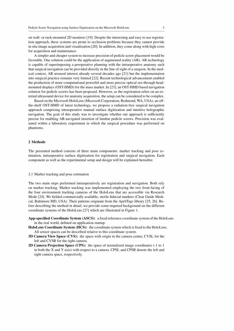
The two main steps performed intraoperatively are registration and navigation. Both relyon marker tracking. Marker tracking was implemented employing the two front-facing ofthe four environment tracking cameras of the HoloLens that are accessible via ResearchMode [24]. We fielded commercially available, sterile fiducial markers (Clear Guide Medi-cal, Baltimore MD, USA). Their patterns originate from the AprilTags library [25, 26]. Be-fore describing the method in detail, we provide some required background on the differentcoordinate systems of the HoloLens [27] which are illustrated in Figure 1.
App-specified Coordinate System (ASCS): a fixed reference coordinate system of the HoloLensin the real world, defined on application startup.
HoloLens Coordinate System (HCS): the coordinate system which is fixed to the HoloLens.All sensor spaces can be described relative to this coordinate system.
3D Camera View Space (CVS): the space with origin in the camera center, CVSL for theleft and CVSR for the right camera.
2D Camera Projection Space (CPS): the space of normalized image coordinates (-1 to 1in both the X and Y axis) with respect to a camera. CPSL and CPSR denote the left andright camera space, respectively.
4 Florentin Liebmann1,2 et al.
CPSL
CPSR
ASCS
HCSCVSL
CVSR
Fig. 1: Exemplary illustration of the HoloLens’ coordinate systems used: App-specified Co-ordinate System (ASCS), HoloLens Coordinate System (HCS), 3D Camera View Space(CVS, left and right) and 2D Camera Projection Space (CPS, left and right). The HoloLens3D model originates from “Free Hololens Model + Textures” by EdgeFlow Studio and theanchor 3D model from “Medieval Anchor” by wolfgar74. Both are licensed under CC BY4.0.
An exemplary transformation from CPS to CVS is denoted as TCV SCPS . For each pair of
images (left and right) with a detectable marker, its pose was derived as follows. Initialestimate values CL
1 , . . . ,CL4 and CR
1 , . . . ,CR4 of the four corners of the marker are detected in
both images using standard detection method [28–30]. Due to the poor resolution (480x640pixels) of the environmental cameras, each Ci was passed to a dedicated Kalman filter [31,32]. We integrated a constant velocity model in the filters, because movements of the surgeonbetween consecutive frames can be considered as constant given the high rate of 30 framesper second. A process noise covariance of 1×10⁻⁵ was assumed in the prediction step of thefilter. The measurement noise 1×10⁻⁴ of the update step was determined heuristically fromexperimental data in which both estimated and ground truth marker corners were known.
The filtered corner estimates were transformed to CPS and extended by one dimension(unit plane: z = 1) such that they can be expressed in CVS and further transformed to HCS.In order to perform triangulation, directional vectors dL
i and dRi between each T HCS
CPSLCLi and
T HCSCPSRCR
i and their respective camera centers have to be formed. The triangulation can becompleted by finding the closest point min(dL
i ,dRi ) between each pair of directional vectors.
Pedicle Screw Navigation using Surface Digitization on the Microsoft HoloLens 5
Given the new 3D estimates min(dLi ,dR
i ), the 3D marker pose can be derived by incor-porating prior knowledge about the marker geometry. As the true 3D position gti of eachcorner point with respect to the marker center is known, the 3D pose estimation problemcan be reduced to the problem of finding a rigid transformation between the point pairsmin(dL
i ,dRi ) and gti in a least-square sense. The transformation is calculated by applying the
absolute orientation [33].
2.2 Registration
The key idea of our intraoperative surface digitization approach is the establishment of acorrespondence between pre- and intra-operative anatomy without needing intraoperativeimaging.
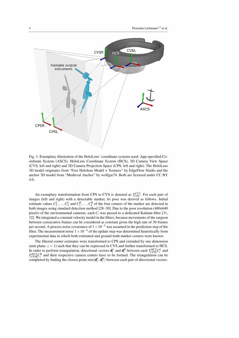
For each vertebra a sparse point cloud of relevant bone surface regions is collected bythe surgeon in the surgery. A custom-made pointing device (PD), as illustrated in Figure 2a,is used for performing surface acquisition. The PD consists of a notch, a handle and tip. Thetip is tapered in a way such that points can be reached at different angles without introducingan offset. The notch can be mounted with sterile fiducial markers such as the ones describedin Section 2.1. Due to the known geometry of the PD, it is straightforward to extrapolatefrom the marker pose to the position of the tip.
(a) (b) (c) (d)
Fig. 2: a) The pointing device. b) A surgeon wearing the HoloLens uses the pointing devicein the experimental setup. c) The augmented view of the surgeon during surface sampling.d) Overlay of vertebra L1 after registration (insertion points are denoted in blue).
After application startup, the surgeon is asked to sample accessible surface regions ofthe vertebra (see Figure 2b) in a specific pattern which was trained previously. To do so,the PD is moved along the anatomy while pressing down the button of the HoloLens clicker[34] (events implemented in MixedRealityToolkit-Unity [35]). For each camera frame themarker tracking method of Section 2.1 is applied and the 3D tip position is recorded, aslong as the button remains pressed. Sampled areas are visualized by a thin line connectingconsecutively collected points (see Figure 2c). Once the button is released, a voice command(events implemented in MixedRealityToolkit-Unity [35]) can be used to indicate whethera collected region should be saved (“save”) or discarded (“delete”). Only the saved points
6 Florentin Liebmann1,2 et al.
were used in the registration process. When sufficient points have been sampled, the surgeoninitiates registration by a double click.
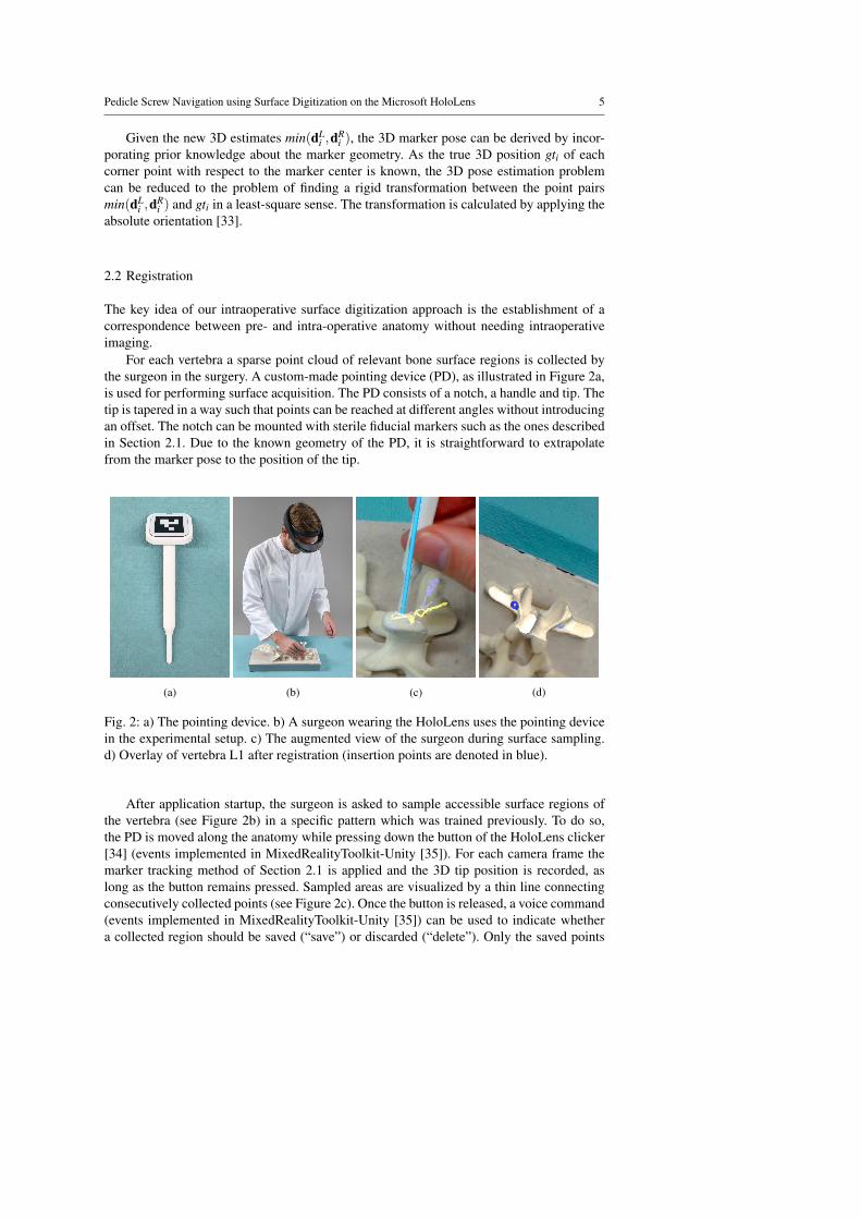
Fig. 3: Template for the bone surface of spine segments L1 - L5 that is assumed to beaccessible intraoperatively (colored areas). The template was constructed by a surgeon.
The intraoperatively collected point cloud pcintra is registered to the point cloud pcprerepresenting the points of the 3D model of the preoperative vertebra. pcpre has been obtainedfrom the 3D triangular surface model (herein after called 3D model) of the segmented pre-operative CT scan (see Section 2.4). In a preprocessing step, pcpre is trimmed by removingpoints which can definitely not be reached with the PD in a surgery. The points are identifiedby using a template model which encodes intraoperatively accessible regions (see Figure 3).
The registration process works in a fully automated fashion and comprising three steps:coarse registration, iterative closest point (ICP) based fine registration [36], and result se-lection. Coarse registration is achieved by identifying three corresponding extremal pointsin each of the point clouds. To this end, a principle component analysis (PCA) [37], imple-mented in ALGLIB (ALGLIB Project, Nizhny Novgorod, Russia), is performed on pcintra,yielding the respective principle axes paintra
1 , paintra2 and paintra
3 ordered by decreasing mag-nitude. The three extremal points eintra
1 , eintra2 and eintra
3 are determined using the dot productas follows:
eintra1 = max(paintra
1 · pi, pi ∈ pcintra)
eintra2 = min(paintra
1 · pi, pi ∈ pcintra)
eintra3 = max(abs(paintra
2 · pi, pi ∈ pcintra))
Correspondingly, the extrema points epre1 , epre
2 and epre3 are calculated. Due to the sym-
metry of the vertebra along pa1, two possible coarse registration configurations must beevaluated (see Figures 4a and 4b) and considered for the fine registration by applying abso-lute orientation [33] to both point pair sets.
{(eintra1 ,epre
1 )},{(eintra2 ,epre
2 )},{(eintra3 ,epre
3 )}{(eintra
1 ,epre2 )},{(eintra
2 ,epre1 )},{(eintra
3 ,epre3 )}
Afterwards, fine registration is performed using ICP on both configurations. Thereby, thealgorithm is terminated when either the number of iterations exceeds 50 or the difference in
Pedicle Screw Navigation using Surface Digitization on the Microsoft HoloLens 7
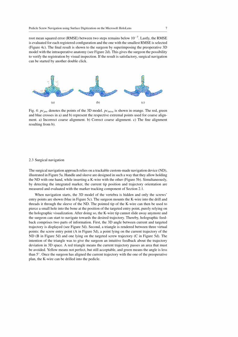
root mean squared error (RMSE) between two steps remains below 10−7. Lastly, the RMSEis evaluated for each registered configuration and the one with the smallest RMSE is selected(Figure 4c). The final result is shown to the surgeon by superimposing the preoperative 3Dmodel with the intraoperative anatomy (see Figure 2d). This gives the surgeon the possibilityto verify the registration by visual inspection. If the result is satisfactory, surgical navigationcan be started by another double click.
(a) (b) (c)
Fig. 4: pcpre denotes the points of the 3D model. pcintra is shown in orange. The red, greenand blue crosses in a) and b) represent the respective extremal points used for coarse align-ment. a) Incorrect coarse alignment. b) Correct coarse alignment. c) The fine alignmentresulting from b).
2.3 Surgical navigation
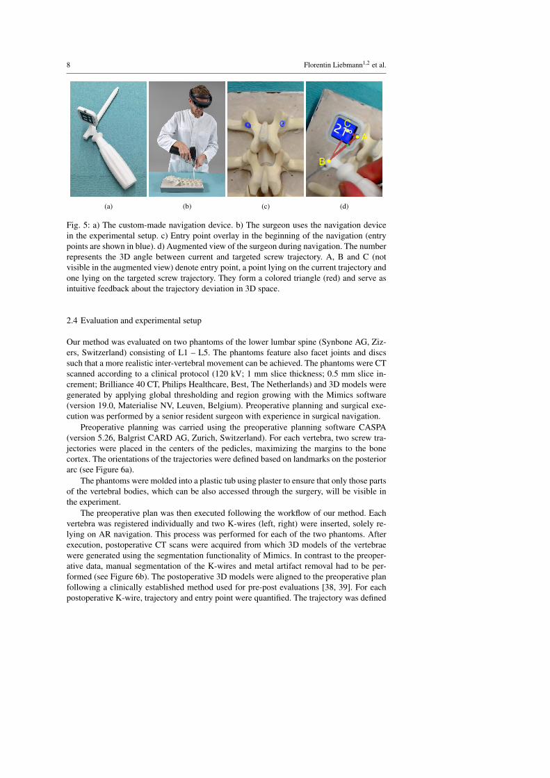
The surgical navigation approach relies on a trackable custom-made navigation device (ND),illustrated in Figure 5a. Handle and sleeve are designed in such a way that they allow holdingthe ND with one hand, while inserting a K-wire with the other (Figure 5b). Simultaneously,by detecting the integrated marker, the current tip position and trajectory orientation aremeasured and evaluated with the marker tracking component of Section 2.1.
When navigation starts, the 3D model of the vertebra is hidden and only the screws’entry points are shown (blue in Figure 5c). The surgeon mounts the K-wire into the drill andthreads it through the sleeve of the ND. The pointed tip of the K-wire can then be used topierce a small hole into the bone at the position of the targeted entry point, purely relying onthe holographic visualization. After doing so, the K-wire tip cannot slide away anymore andthe surgeon can start to navigate towards the desired trajectory. Thereby, holographic feed-back comprises two parts of information. First, the 3D angle between current and targetedtrajectory is displayed (see Figure 5d). Second, a triangle is rendered between three virtualpoints: the screw entry point (A in Figure 5d), a point lying on the current trajectory of theND (B in Figure 5d) and one lying on the targeted screw trajectory (C in Figure 5d). Theintention of the triangle was to give the surgeon an intuitive feedback about the trajectorydeviation in 3D space. A red triangle means the current trajectory passes an area that mustbe avoided. Yellow means not perfect, but still acceptable, and green means the angle is lessthan 5◦. Once the surgeon has aligned the current trajectory with the one of the preoperativeplan, the K-wire can be drilled into the pedicle.
8 Florentin Liebmann1,2 et al.
(a) (b) (c)
A
B
C
(d)
Fig. 5: a) The custom-made navigation device. b) The surgeon uses the navigation devicein the experimental setup. c) Entry point overlay in the beginning of the navigation (entrypoints are shown in blue). d) Augmented view of the surgeon during navigation. The numberrepresents the 3D angle between current and targeted screw trajectory. A, B and C (notvisible in the augmented view) denote entry point, a point lying on the current trajectory andone lying on the targeted screw trajectory. They form a colored triangle (red) and serve asintuitive feedback about the trajectory deviation in 3D space.
2.4 Evaluation and experimental setup
Our method was evaluated on two phantoms of the lower lumbar spine (Synbone AG, Ziz-ers, Switzerland) consisting of L1 – L5. The phantoms feature also facet joints and discssuch that a more realistic inter-vertebral movement can be achieved. The phantoms were CTscanned according to a clinical protocol (120 kV; 1 mm slice thickness; 0.5 mm slice in-crement; Brilliance 40 CT, Philips Healthcare, Best, The Netherlands) and 3D models weregenerated by applying global thresholding and region growing with the Mimics software(version 19.0, Materialise NV, Leuven, Belgium). Preoperative planning and surgical exe-cution was performed by a senior resident surgeon with experience in surgical navigation.
Preoperative planning was carried using the preoperative planning software CASPA(version 5.26, Balgrist CARD AG, Zurich, Switzerland). For each vertebra, two screw tra-jectories were placed in the centers of the pedicles, maximizing the margins to the bonecortex. The orientations of the trajectories were defined based on landmarks on the posteriorarc (see Figure 6a).
The phantoms were molded into a plastic tub using plaster to ensure that only those partsof the vertebral bodies, which can be also accessed through the surgery, will be visible inthe experiment.
The preoperative plan was then executed following the workflow of our method. Eachvertebra was registered individually and two K-wires (left, right) were inserted, solely re-lying on AR navigation. This process was performed for each of the two phantoms. Afterexecution, postoperative CT scans were acquired from which 3D models of the vertebraewere generated using the segmentation functionality of Mimics. In contrast to the preoper-ative data, manual segmentation of the K-wires and metal artifact removal had to be per-formed (see Figure 6b). The postoperative 3D models were aligned to the preoperative planfollowing a clinically established method used for pre-post evaluations [38, 39]. For eachpostoperative K-wire, trajectory and entry point were quantified. The trajectory was defined
Pedicle Screw Navigation using Surface Digitization on the Microsoft HoloLens 9
(a) (b) (c) (d)
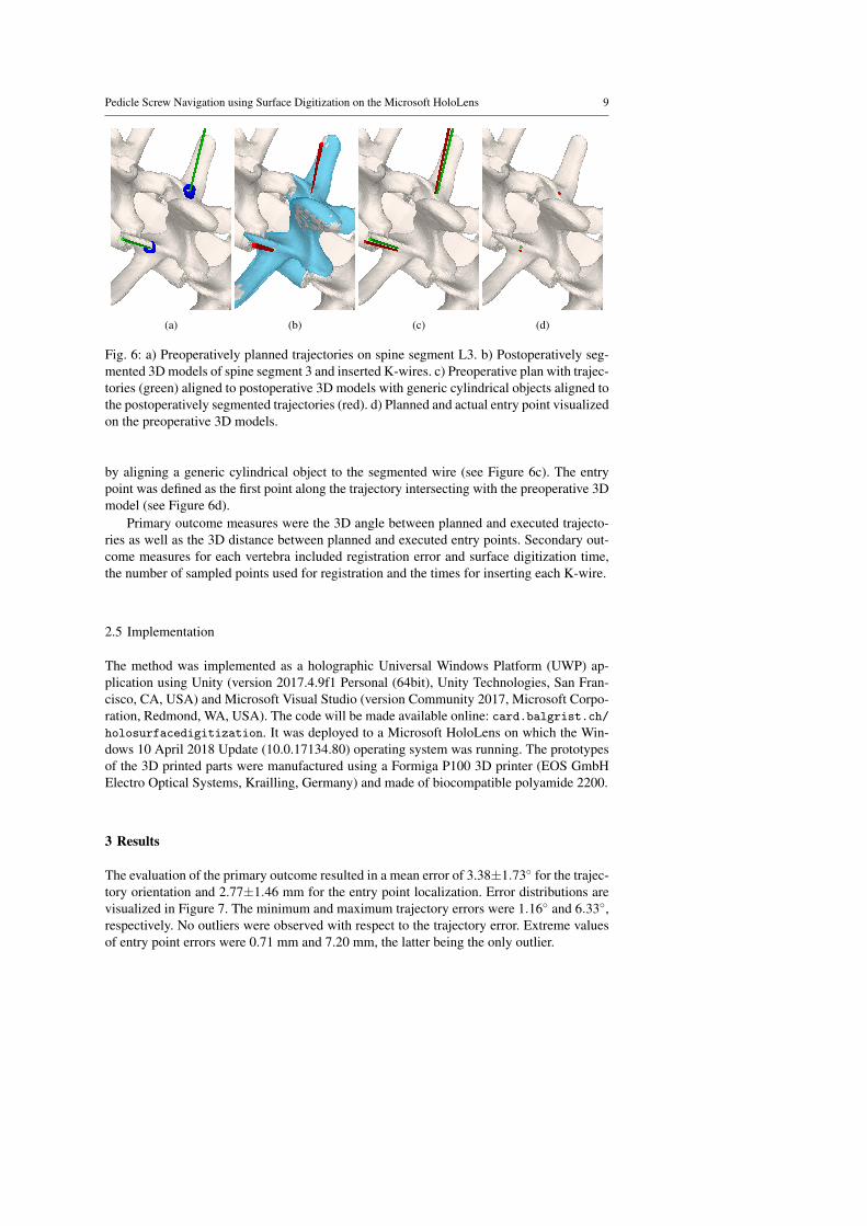
Fig. 6: a) Preoperatively planned trajectories on spine segment L3. b) Postoperatively seg-mented 3D models of spine segment 3 and inserted K-wires. c) Preoperative plan with trajec-tories (green) aligned to postoperative 3D models with generic cylindrical objects aligned tothe postoperatively segmented trajectories (red). d) Planned and actual entry point visualizedon the preoperative 3D models.
by aligning a generic cylindrical object to the segmented wire (see Figure 6c). The entrypoint was defined as the first point along the trajectory intersecting with the preoperative 3Dmodel (see Figure 6d).
Primary outcome measures were the 3D angle between planned and executed trajecto-ries as well as the 3D distance between planned and executed entry points. Secondary out-come measures for each vertebra included registration error and surface digitization time,the number of sampled points used for registration and the times for inserting each K-wire.
2.5 Implementation
The method was implemented as a holographic Universal Windows Platform (UWP) ap-plication using Unity (version 2017.4.9f1 Personal (64bit), Unity Technologies, San Fran-cisco, CA, USA) and Microsoft Visual Studio (version Community 2017, Microsoft Corpo-ration, Redmond, WA, USA). The code will be made available online: card.balgrist.ch/holosurfacedigitization. It was deployed to a Microsoft HoloLens on which the Win-dows 10 April 2018 Update (10.0.17134.80) operating system was running. The prototypesof the 3D printed parts were manufactured using a Formiga P100 3D printer (EOS GmbHElectro Optical Systems, Krailling, Germany) and made of biocompatible polyamide 2200.
3 Results
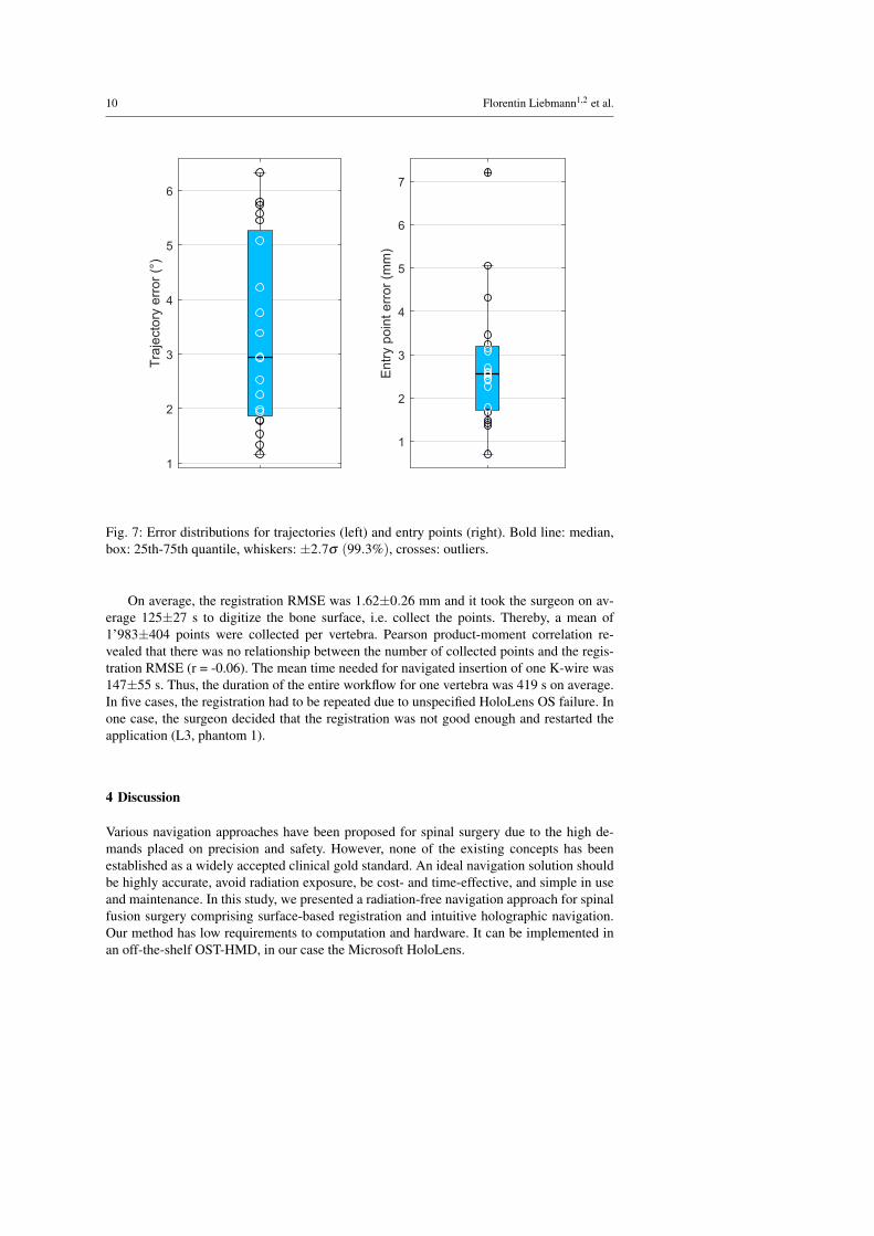
The evaluation of the primary outcome resulted in a mean error of 3.38±1.73◦ for the trajec-tory orientation and 2.77±1.46 mm for the entry point localization. Error distributions arevisualized in Figure 7. The minimum and maximum trajectory errors were 1.16◦ and 6.33◦,respectively. No outliers were observed with respect to the trajectory error. Extreme valuesof entry point errors were 0.71 mm and 7.20 mm, the latter being the only outlier.
10 Florentin Liebmann1,2 et al.
1
2
3
4
5
6
Tra
jecto
ry e
rror
(°)
1
2
3
4
5
6
7
Entr
y p
oin
t err
or
(mm
)
Fig. 7: Error distributions for trajectories (left) and entry points (right). Bold line: median,box: 25th-75th quantile, whiskers: ±2.7σ (99.3%), crosses: outliers.
On average, the registration RMSE was 1.62±0.26 mm and it took the surgeon on av-erage 125±27 s to digitize the bone surface, i.e. collect the points. Thereby, a mean of1’983±404 points were collected per vertebra. Pearson product-moment correlation re-vealed that there was no relationship between the number of collected points and the regis-tration RMSE (r = -0.06). The mean time needed for navigated insertion of one K-wire was147±55 s. Thus, the duration of the entire workflow for one vertebra was 419 s on average.In five cases, the registration had to be repeated due to unspecified HoloLens OS failure. Inone case, the surgeon decided that the registration was not good enough and restarted theapplication (L3, phantom 1).
4 Discussion
Various navigation approaches have been proposed for spinal surgery due to the high de-mands placed on precision and safety. However, none of the existing concepts has beenestablished as a widely accepted clinical gold standard. An ideal navigation solution shouldbe highly accurate, avoid radiation exposure, be cost- and time-effective, and simple in useand maintenance. In this study, we presented a radiation-free navigation approach for spinalfusion surgery comprising surface-based registration and intuitive holographic navigation.Our method has low requirements to computation and hardware. It can be implemented inan off-the-shelf OST-HMD, in our case the Microsoft HoloLens.
Pedicle Screw Navigation using Surface Digitization on the Microsoft HoloLens 11
Several intraoperative surface digitization approaches that eliminate the need of intraop-erative imaging have been evaluated in clinical settings [16–18]. They can be considered asvery precise, if relying on expensive optical tracking devices. Nottmeier et al. [16] reporteda mean registration error of 0.9 mm which is comparable to our RMSE of 1.62 mm on av-erage. In terms of screw insertion accuracy, the results of Ma et al. [23] were similar (3.35mm, 2.74◦) to ours (2.77 mm, 3.38◦) although a comprehensive high-end system was used.Due to these promising results with respect to accuracy, our low-cost navigation solutionmay have the potential for clinical use.
A different, yet very popular navigation method is 3D printing of patient-specific instru-ments (PSI) [9]. However, the main drawback of PSI systems are high production costs percase and long production time. Merc et al. [10] employed PSI in a randomized clinical trialto evaluate navigated pedicle screw placement accuracy in comparison to a control groupwhere the fluoroscopy-controlled free-hand technique was used. For the lumbar segment,they reported a deviation of the entry point by 0.3 mm (interventional group) vs. 1.5 mm(control group) in the sagittal and 0.7 mm vs. 0.2 mm in the transversal plane. The sagittaland transversal deviations with respect to trajectory orientation were 1◦ vs. 6◦ and 1◦ vs 0◦,respectively. Although differences were statistically significant for the sagittal comparisons,PSI navigation still showed a high standard deviation of the error.
Navigation methods are often criticized because their application can result in an in-crease of the surgery time. At least, the evaluation of the mean registration time in our study(125 s) was similar to state-of-the-art optical navigation system (117 s) [16]. PSI-navigatedpedicle screw placement is faster than intraoperative surface digitization as the registrationcan be performed by placing the PSI on the bone surface. Farshad et al. reported an averagetime of 74 s for pedicle screw placement [9]. However, their study did not consider the timerequired to debride the bone from periosteum which is a necessary preparation step beforePSI placement [38, 39].
Similar to our study, attempts have been made to develop simpler and more cost-effectivetechniques for navigation of pedicle screw insertion. Walti et al. [40] developed a small,custom-built device that relies on an inertial measurement unit. They conducted a pre-clinical cadaver study achieving an accuracy of 2.7◦ and 3.5◦ in the sagittal and axial plane,respectively. However, the approach lacked guidance of the screws’ entry points and it pro-vided registration only based on specific bony landmark points. Relying on the identificationof specific bony landmarks is known to be error-prone. The study of Gibby et al. [41] evalu-ated the feasibility of the HoloLens for navigating a needle percutaneously to mimic pediclescrew placement. The target for needle placement was a lumbar spine phantom, wrapped inan opaque silicon block. Intraoperative registration was carried out using commercial soft-ware which then was refined manually by the user. The registration process was the mainlimitation of the study: It is based on intraoperative CT and the object to be registered needsto be simple and large, such as the silicon block.
This study has several limitations. The evaluation was performed on bone phantomswhich did not include surrounding soft tissue structures. In a real surgery, such soft tis-sue structures could have a negative influence on the sampling process. However, we usedspecific bone regions for sampling that are known to be accessible in open surgery (seeFigure 3). Other studies have also demonstrated that a similar registration accuracy can beachieved regardless whether phantoms or cadavers were used [23]. Furthermore, unlike inreal surgery, the anatomy was rigidly attached to the table and thus could not move. Forthis reason, no motion compensation strategy was necessary, but it is known that Hologramsare prone to drift once they have been placed [42]. Even though the surgeon tried to mini-mize head movement, drift may have negatively influenced our results. Finally, the proposed

12 Florentin Liebmann1,2 et al.
method is partly constrained by current technical limitations of the HoloLens. It can be as-sumed that increased sensor quality in future releases will improve the accuracy of built-intracking methods.
For future work, we plan to carry out a comprehensive cadaver evaluation on humanspecimen to evaluate clinical feasibility and surgical outcomes compared to the free-handtechnique. The study shall include evaluation of subjective feedback on acceptance and us-ability by the performing surgeons. Furthermore, the intraoperative manual surface digiti-zation quality on real anatomy needs to be assessed. Post-experimental analysis has alsorevealed that the sampling surfaces contained outliers not belonging to the actual bone sur-face. The precision of the registration may be further increased by developing an outlierremoval strategy. Concluding, our preliminary evaluation indicates a precision which maybe sufficient for clinical application.
Compliance with Ethical Standards
– Conflict of Interest: The authors declare that they have no conflict of interest.– This article does not contain any studies with human participants or animals performed
by any of the authors.– This articles does not contain patient data.
References
1. Raciborski F, Gasik R, Kłak A (2016) Disorders of the spine. a major health and socialproblem. Reumatologia 54(4):196
2. Vos T, Flaxman AD, Naghavi M, Lozano R, Michaud C, Ezzati M, Shibuya K, SalomonJA, Abdalla S, Aboyans V, et al. (2012) Years lived with disability (ylds) for 1160sequelae of 289 diseases and injuries 1990–2010: a systematic analysis for the globalburden of disease study 2010. The lancet 380(9859):2163–2196
3. Van Tulder MW, Koes BW, Bouter LM (1997) Conservative treatment of acute andchronic nonspecific low back pain: a systematic review of randomized controlled trialsof the most common interventions. Spine 22(18):2128–2156
4. Mirza SK, Deyo RA (2007) Systematic review of randomized trials comparing lumbarfusion surgery to nonoperative care for treatment of chronic back pain. Spine 32(7):816–823
5. Verlaan J, Diekerhof C, Buskens E, Van der Tweel I, Verbout A, Dhert W, Oner F (2004)Surgical treatment of traumatic fractures of the thoracic and lumbar spine: a systematicreview of the literature on techniques, complications, and outcome. Spine 29(7):803–814
6. Maruyama T, Takeshita K (2008) Surgical treatment of scoliosis: a review of techniquescurrently applied. Scoliosis 3(1):6
7. Mason A, Paulsen R, Babuska JM, Rajpal S, Burneikiene S, Nelson EL, VillavicencioAT (2014) The accuracy of pedicle screw placement using intraoperative image guid-ance systems: A systematic review. Journal of Neurosurgery: Spine 20(2):196–203
8. Modi HN, Suh SW, Fernandez H, Yang JH, Song HR (2008) Accuracy and safety ofpedicle screw placement in neuromuscular scoliosis with free-hand technique. EuropeanSpine Journal 17(12):1686–1696
Pedicle Screw Navigation using Surface Digitization on the Microsoft HoloLens 13
9. Farshad M, Betz M, Farshad-Amacker NA, Moser M (2017) Accuracy of patient-specific template-guided vs. free-hand fluoroscopically controlled pedicle screw place-ment in the thoracic and lumbar spine: a randomized cadaveric study. European SpineJournal 26(3):738–749
10. Merc M, Drstvensek I, Vogrin M, Brajlih T, Recnik G (2013) A multi-level rapid pro-totyping drill guide template reduces the perforation risk of pedicle screw placement inthe lumbar and sacral spine. Archives of orthopaedic and trauma surgery 133(7):893–899
11. Kantelhardt SR, Martinez R, Baerwinkel S, Burger R, Giese A, Rohde V (2011) Periop-erative course and accuracy of screw positioning in conventional, open robotic-guidedand percutaneous robotic-guided, pedicle screw placement. European Spine Journal20(6):860–868
12. Tian NF, Huang QS, Zhou P, Zhou Y, Wu RK, Lou Y, Xu HZ (2011) Pedicle screw in-sertion accuracy with different assisted methods: a systematic review and meta-analysisof comparative studies. European Spine Journal 20(6):846–859
13. Narain AS, Hijji FY, Yom KH, Kudaravalli KT, Haws BE, Singh K (2017) Radiationexposure and reduction in the operating room: Perspectives and future directions inspine surgery. World journal of orthopedics 8(7):524
14. Gebhard FT, Kraus MD, Schneider E, Liener UC, Kinzl L, Arand M (2006)Does computer-assisted spine surgery reduce intraoperative radiation doses? Spine31(17):2024–2027
15. Slomczykowski M, Roberto M, Schneeberger P, Ozdoba C, Vock P (1999) Radiationdose for pedicle screw insertion: fluoroscopic method versus computer-assisted surgery.Spine 24(10):975–983
16. Nottmeier EW, Crosby TL (2007) Timing of paired points and surface matching regis-tration in three-dimensional (3d) image-guided spinal surgery. Clinical Spine Surgery20(4):268–270
17. Richter M, Cakir B, Schmidt R (2005) Cervical pedicle screws: conventional versuscomputer-assisted placement of cannulated screws. Spine 30(20):2280–2287
18. Chiang CF, Tsai TT, Chen LH, Lai PL, Fu TS, Niu CC, Chen WJ (2012) Computedtomography-based navigation-assisted pedicle screw insertion for thoracic and lumbarspine fractures. Chang Gung Med J 35(4):332–8
19. Qian L, Unberath M, Yu K, Fuerst B, Johnson A, Navab N, Osgood G (2017) To-wards virtual monitors for image guided interventions-real-time streaming to opticalsee-through head-mounted displays. arXiv preprint arXiv:171000808
20. Andress S, Johnson A, Unberath M, Winkler AF, Yu K, Fotouhi J, Weidert S, OsgoodG, Navab N (2018) On-the-fly augmented reality for orthopedic surgery using a multi-modal fiducial. Journal of Medical Imaging 5(2):021209
21. Sielhorst T, Feuerstein M, Navab N (2008) Advanced medical displays: A literaturereview of augmented reality. Journal of Display Technology 4(4):451–467
22. Navab N, Blum T, Wang L, Okur A, Wendler T (2012) First deployments of augmentedreality in operating rooms. Computer 45(7):48–55
23. Ma L, Zhao Z, Chen F, Zhang B, Fu L, Liao H (2017) Augmented reality surgicalnavigation with ultrasound-assisted registration for pedicle screw placement: a pilotstudy. International journal of computer assisted radiology and surgery 12(12):2205–2215
24. Microsoft (2018) HoloLens Research mode. https://docs.microsoft.com/en-us/windows/mixed-reality/research-mode. Accessed 2018-11-01
14 Florentin Liebmann1,2 et al.
25. Olson E (2011) Apriltag: A robust and flexible visual fiducial system. In: Robotics andAutomation (ICRA), 2011 IEEE International Conference on, IEEE, pp 3400–3407
26. Wang J, Olson E (2016) Apriltag 2: Efficient and robust fiducial detection. In: IROS, pp4193–4198
27. Microsoft (2018) Locatable camera. https://docs.microsoft.com/en-us/windows/mixed-reality/locatable-camera. Accessed 2018-11-05
28. Garrido-Jurado S, Munoz-Salinas R, Madrid-Cuevas FJ, Marın-Jimenez MJ (2014) Au-tomatic generation and detection of highly reliable fiducial markers under occlusion.Pattern Recognition 47(6):2280–2292
29. Garrido-Jurado S, Munoz-Salinas R, Madrid-Cuevas FJ, Medina-Carnicer R (2016)Generation of fiducial marker dictionaries using mixed integer linear programming. Pat-tern Recognition 51:481–491
30. Romero-Ramirez FJ, Munoz-Salinas R, Medina-Carnicer R (2018) Speeded up detec-tion of squared fiducial markers. Image and Vision Computing
31. Kalman RE (1960) A new approach to linear filtering and prediction problems. Journalof basic Engineering 82(1):35–45
32. Bradski G, Kaehler A (2000) Opencv. Dr Dobb’s journal of software tools 333. Horn BK (1987) Closed-form solution of absolute orientation using unit quaternions.
JOSA A 4(4):629–64234. Microsoft (2017) Use the HoloLens clicker. https://support.microsoft.com/de-
ch/help/12646/hololens-use-the-hololens-clicker. Accessed 2018-11-0335. Microsoft (2018) HoloToolkit 2017.4.1.0. https://github.com/Microsoft/MixedRealityToolkit-
Unity/releases/tag/2017.4.1.0. Accessed 2018-11-0336. Besl PJ, McKay ND (1992) Method for registration of 3-d shapes. In: Sensor Fusion IV:
Control Paradigms and Data Structures, International Society for Optics and Photonics,vol 1611, pp 586–607
37. Pearson K (1901) Liii. on lines and planes of closest fit to systems of points in space.The London, Edinburgh, and Dublin Philosophical Magazine and Journal of Science2(11):559–572
38. Schweizer A, Mauler F, Vlachopoulos L, Nagy L, Furnstahl P (2016) Computer-assisted3-dimensional reconstructions of scaphoid fractures and nonunions with and without theuse of patient-specific guides: early clinical outcomes and postoperative assessments ofreconstruction accuracy. The Journal of hand surgery 41(1):59–69
39. Roner S, Vlachopoulos L, Nagy L, Schweizer A, Furnstahl P (2017) Accuracy andearly clinical outcome of 3-dimensional planned and guided single-cut osteotomies ofmalunited forearm bones. The Journal of hand surgery 42(12):1031–e1
40. Walti J, Jost GF, Cattin PC (2014) A new cost-effective approach to pedicular screwplacement. In: Workshop on Augmented Environments for Computer-Assisted Inter-ventions, Springer, pp 90–97
41. Gibby JT, Swenson SA, Cvetko S, Rao R, Javan R (2018) Head-mounted display aug-mented reality to guide pedicle screw placement utilizing computed tomography. Inter-national Journal of Computer Assisted Radiology and Surgery pp 1–11
42. Vassallo R, Rankin A, Chen EC, Peters TM (2017) Hologram stability evaluation formicrosoft hololens. In: Medical Imaging 2017: Image Perception, Observer Perfor-mance, and Technology Assessment, International Society for Optics and Photonics,vol 10136, p 1013614