Embed Size (px)
DESCRIPTION
TR *N sT”B ETMS E R I E SA AIntended to alert the user to the presence of uninsulated “dangerous voltage” within the product’s enclosure that may be of sufficient magnitude to constitute a risk of electric shock to persons. Intended to alert the user of the presence of important operating and maintenance (servicing) instructions in the literature accompanying the product.CAUTION: Risk of electrical shock - DO NOT OPEN! CAUTION: To reduce the risk of electric shock, do not remo
Citation preview

S E R I E ST R * N s T ” B ETM

A Intended to alert the user to the presence of uninsulated “dangerous voltage” within the product’s enclosurethat may be of sufficient magnitude to constitute a risk of electric shock to persons.
A Intended to alert the user of the presence of important operating and maintenance (servicing) instructions in theliterature accompanying the product.
CAUTION: Risk of electrical shock - DO NOT OPEN!CAUTION: To reduce the risk of electric shock, do not remove cover. No user serviceable parts inside. Refer servicing toqualified service personnel.
WARNING: To prevent electrical shock or fire hazard, do not expose this appliance to rain or moisture. Before using thisappliance, read the operating guide for further warnings.
A Este simbolo tiene el prop6sito de alertar al usuario de la presencia de “(voltaje) peligroso” que no tieneaislamiento dentro de la caja de1 product0 que puede tener una magnitud suficiente coma para constituir riesgo decorrientazo.
A Este simbolo tiene el prop6sito de alertar al usario de la presencia de instruccones importantes sobre la operaci6ny mantenimiento en la literatura que viene con el producto.
PRECAUCION: Riesgo de corrientazo - No abra.PRECAUCION: Para disminuir el riesgo de corrientazo, no abra la cubierta. No hay piezas adentro que el usario puedareparar. Deje todo mantenimiento a 10s t&cnicos calificados.
ADVERTENCIA: Para evitar corrientazos o peligro de incendio, no deje expuesto a la lluvia o humedad este aparatoAntes de usar este aparato, lea m8s advertencias en la guia de operaci6n.
A Ce symbole est utilisk pur indiquer 2 l’utilisateur la presence B l’interieur de ce produit de tension non-isoleedangereuse pouvant ctre d’intensitk suffisante pour constituer un risque de choc klectrique.
A Ce symbole est utilis6 pour indiquer i l’utilisateur qu’il ou qu’elle trouvera d’importantes instructions surl’utilisation et l’entretien (service) de l’appareil dans la littkrature accompagnant le produit.
ATTENTION: Risques de choc electrique - NE PAS OUVRIR!ATTENTION: Afin de riduire le risque de choc klectrique, ne pas enlever le couvercle. I1 ne se trouve j l’intkrieuraucune pi&e pouvant etre r6par6e par l’utilisateur. Confier l’entretien & un personnel qualifik.
AVERTISSEMENT: Afin de prevenir les risques de dkcharge ilectrique ou de feu, n’exposez pas cet appareil & la pluieou & I’humidite. Avant d’utiliser cet appareil, lisez les avertissements suppl6mentaires situ& dans le guide.
A Dieses Symbol sol1 den Anwender vor unisolierten gefghrlichen Spannungen innerhalb des Gehguses warnen, dievon Ausreichender Stgrke sind, urn einen elektrischen Schlag verursachen zu kiinnen.
A Dieses Symbol sol1 den Benutzer auf wichtige Instruktionen in der Bedienungsanleitung aufmerksam machen, dieHandhabung und Wartung des Produkts betreffen.
VORSICHT: Risiko - Elektrischer Schlag! Nicht iiffnen!VORSICHT: Urn das Risiko eines elektrischen Schlages zu vermeiden, nicht die Abdeckung enfernen. Es befinden sichkeine Teile darin, die vom Anwender repariert werden kiinnten. Reparaturen nur von qualifiziertem Fachpersonaldurchfiihren lassen.
ACHTUNG: Urn einen elektrischen Schlag oder Feuergefahr zu vermeiden, sollte dieses Ger%t nicht dem Regen oderFeuchtigkeit ausgesetzt werden. Vor Inbetriebnahme unbedingt die Bedienungsanleitung lesen.
2
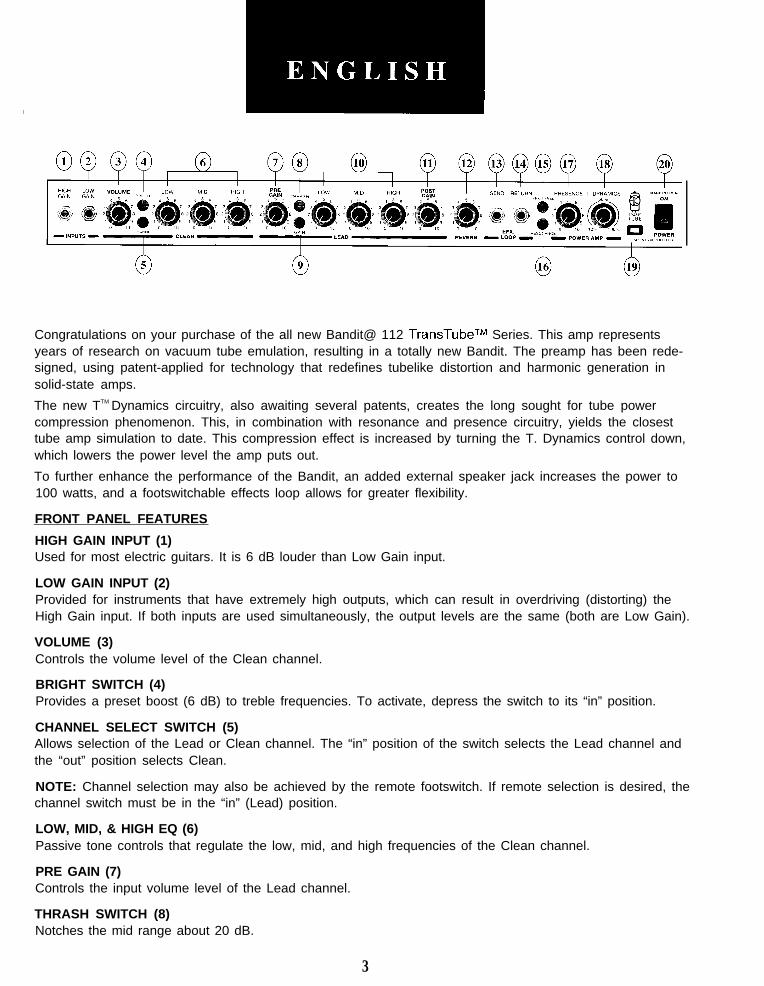
Congratulations on your purchase of the all new Bandit@ 112 TransTubeTM Series. This amp representsyears of research on vacuum tube emulation, resulting in a totally new Bandit. The preamp has been rede-signed, using patent-applied for technology that redefines tubelike distortion and harmonic generation insolid-state amps.
The new TTM Dynamics circuitry, also awaiting several patents, creates the long sought for tube powercompression phenomenon. This, in combination with resonance and presence circuitry, yields the closesttube amp simulation to date. This compression effect is increased by turning the T. Dynamics control down,which lowers the power level the amp puts out.
To further enhance the performance of the Bandit, an added external speaker jack increases the power to100 watts, and a footswitchable effects loop allows for greater flexibility.
FRONT PANEL FEATURES
HIGH GAIN INPUT (1)Used for most electric guitars. It is 6 dB louder than Low Gain input.
LOW GAIN INPUT (2)Provided for instruments that have extremely high outputs, which can result in overdriving (distorting) theHigh Gain input. If both inputs are used simultaneously, the output levels are the same (both are Low Gain).
VOLUME (3)Controls the volume level of the Clean channel.
BRIGHT SWITCH (4)Provides a preset boost (6 dB) to treble frequencies. To activate, depress the switch to its “in” position.
CHANNEL SELECT SWITCH (5)Allows selection of the Lead or Clean channel. The “in” position of the switch selects the Lead channel andthe “out” position selects Clean.
NOTE: Channel selection may also be achieved by the remote footswitch. If remote selection is desired, thechannel switch must be in the “in” (Lead) position.
LOW, MID, & HIGH EQ (6)Passive tone controls that regulate the low, mid, and high frequencies of the Clean channel.
PRE GAIN (7)Controls the input volume level of the Lead channel.
THRASH SWITCH (8)Notches the mid range about 20 dB.
3
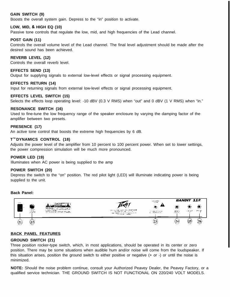
GAIN SWITCH (9)Boosts the overall system gain. Depress to the “in” position to activate.
LOW, MID, 81 HIGH EQ (10)Passive tone controls that regulate the low, mid, and high frequencies of the Lead channel.
POST GAIN (11)Controls the overall volume level of the Lead channel. The final level adjustment should be made after thedesired sound has been achieved.
REVERB LEVEL (12)Controls the overall reverb level.
EFFECTS SEND (13)Output for supplying signals to external low-level effects or signal processing equipment.
EFFECTS RETURN (14)Input for returning signals from external low-level effects or signal processing equipment.
EFFECTS LEVEL SWITCH (15)Selects the effects loop operating level: -10 dBV (0.3 V RMS) when “out” and 0 dBV (1 V RMS) when “in.”
RESONANCE SWITCH (16)Used to fine-tune the low frequency range of the speaker enclosure by varying the damping factor of theamplifier between two presets.
PRESENCE (17)An active tone control that boosts the extreme high frequencies by 6 dB.
TTM DYNAMICS CONTROL (18)Adjusts the power level of the amplifier from 10 percent to 100 percent power. When set to lower settings,the power compression simulation will be much more pronounced.
POWER LED (19)Illuminates when AC power is being supplied to the amp
POWER SWITCH (20)Depress the switch to the “on” position. The red pilot light (LED) will illuminate indicating power is beingsupplied to the unit.
Back Panel:
BACK PANEL FEATURES
GROUND SWITCH (21)Three position rocker-type switch, which, in most applications, should be operated in its center or zeroposition. There may be some situations when audible hum and/or noise will come from the loudspeaker. Ifthis situation arises, position the ground switch to either positive or negative (+ or -) or until the noise isminimized.
NOTE: Should the noise problem continue, consult your Authorized Peavey Dealer, the Peavey Factory, or aqualified service technician. THE GROUND SWITCH IS NOT FUNCTIONAL ON 220/240 VOLT MODELS.

LINE CORD-120 V products only (22)
A For your safety, we have incorporated a three-wire line (mains) cable with proper groundingfacilities. It is not advisable to remove the ground pin under any circumstances. If it is neces-sary to use the equipment without proper grounding facilities, suitable grounding adaptorsshould be used. Less noise and greatly reduced shock hazard exists when the unit is oper-ated with properly grounded receptacles.
EXTERNAL SPEAKER JACK (23)
A Provided for connection of external speaker cabinet. Minimum external speaker impedanceis 8 ohms (4 ohm total impedance).
REMOTE SWITCH JACK (24)Provided for the connection of the supplied remote footswitch. The footswitch is used to select the Lead orNormal channels and defeat effects loop. When using remote footswitch, always insert the plug fully (secondclick) to insure proper operation.
POWER AMP INPUT (25)Used to connect line level signal to the power amplifier.
PREAMP OUT (26)The preamp out can be used to route the amplified signal to a mixing console, tape recorder, etc. Connectthe preamp output using a shielded cable to an input of the tape recorder, mixer, etc. This patch does notaffect the operation of the amplifier.

SPECIFICATIONS
Rated Power & Load:Power specs measured with T. Dynamics @ IO
80 W RMS into 8 ohms100 W RMS into 4 ohms
Power @ Clipping: (typically)(5% THD, 1 kHz, 120 V AC line)
80 W RMS into 8 ohms100 W RMS into 4 ohms
Frequency Response:+O, 3 dB, 60 Hz to 20 kHz, @ 65 W RMS
into 8 ohms
Hum & Noise:Greater than 86 dB below rated power
Power Consumption:300 W @I 50/60 Hz, 120 V AC, Domestic300 W @ 60 Hz, 220-230/240 V AC, Export
PREAMP SECTIONThe following specs are measured @ 1 kHz with the controls
preset as folio ws:Push Bright, Off (Out)Channel Select Normal (Out)Low & High @ IOMid @ 0Presence @ 0 dBPre 5: Post Gain @ IOGain 6: Thrash, Off (Out)Normal Levels are with normal volume @ 5
Minimum Levels are with normal volume @ 10
Preamp High Gain Input:Impedance: High-Z, 1 M ohmNominal Input Level: -14 dBV, 200 mV RMSMinimum Input Level: -24 dBV, 60 mV RMSMaximum Input Level: 0 dBV, 1 V RMS
Preamp Low Gain Input:Impedance: High-Z, 44 K ohmsNominal Input Level: -8 dBV, 400 mV RMSMinimum Input Level: -18 dBV, 120 mV RMSMaximum Input Level: 6 dBV, 2 V RMS
Effects Send:Load Impedance: 1 K ohm or greaterNominal Output Level: -10 dBV, 0.3 V RMS or
0 dBV, 1 V RMS if Effects Level is in
Effects Return:Impedance: High-Z, 22 K ohmsDesigned Input Level: -10 dBV, 0.3 V RMS or
0 dBV, 1 V RMS if Effects Level is in
(Switching jack provides Effects Send to EffectsReturn connection when not used)
Preamp Output:Load Impedance: 1 K ohm or greaterNominal Output Level: 0 dBV, 1 V RMS
Power Amp Input:Impedance: High-Z, 30 K ohmsDesigned Input Level: 0 dBV, 1 V RMS
(Switching jack provides preamp output to poweramp input connection when not used)
System Hum & Noise @ Nominal Input Level:(20 Hz to 20 kHz unweighted)
72 dB below rated power
Equalization:Special low, mid, & high passive type EQPresence: +6 dB @ 5 kHzPush Bright: +6 dB @ 2 kHzPush Thrash: -20 dB notch @ 1 kHz in Lead
channelPush Gain: Increases Lead gainPush Resonance: +6 dB @ cabinet resonance
External Footswitch Functions:Lead Channel Defeat (when selected with button)Effects Loop Bypass
Dimensions & Weight:20.0” H x 23.375” D x 11.25” D46.5 Ibs.
T Dynamics R.O.C. Invention Patent No. 072727
A~features and
Due to our eflorts for constant improvements,specifications listed herein are subject to change without
6
6
I-
L
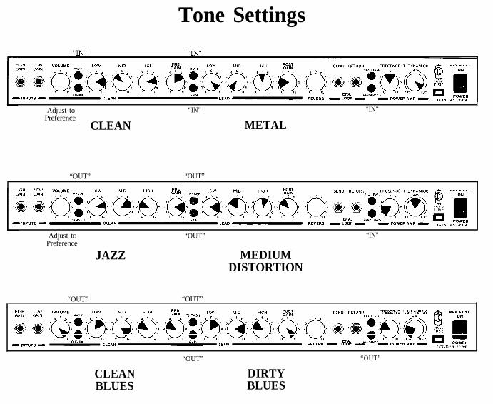
Tone Settings
,
Adjust to “IN” “IN”Preference
CLEAN METAL
“OUT” “OUT”
Adjust toPreference
“OUT” “IN”
JAZZ MEDIUMDISTORTION
“OUT” “OUT”I I
HIGH LOW PHESENCE T DYNAMICSGAIN GAIN
- ,NP”TS L CLEAN LEAD REVERB - LOOP - - POWER AMP -
“OUT” “OUT”
CLEAN DIRTYBLUES BLUES

Consulte 10s diagramas de1 paneldelantero en la seccih de ingl6s de este manual.
Felicitaciones por la adquisicion del nuevo miembro de la serie TransTube, el amplificador Bandit@ 112. Estenovisimo amplificador representa adios de investigation en el campo de la emulation del sonido generadopor 10s tubos de vacio. El preamplificador ha sido redisefiado utilizando una tecnologia en proceso depatentacion que redefine la distorsion similar a la creada por 10s tubos de vacio y la generation armonica en10s amplificadores transistorizados.
El nuevo circuit0 TTM Dynamics, tambien en proceso de patentacion, crea el tan codiciado fenomeno decompresion de potencia que generaban 10s tubos de vacio. Esto, ademas del circuit0 de resonancia ypresencia, produce la simulacicn de amplificador con tubos de vacio m&s fiel que se haya logrado hasta lafecha. Ademas, se puede aumentar el efecto de compresion al bajar el control del circuit0 T. Dynamics, conlo cual se reduce el nivel de potencia que genera el amplificador.
Para un desempefio atin mejor, el amplificador Bandit cuenta con un enchufe para altavoz externo queaumenta la potencia a 100 watts y un circuit0 de efectos conmutables por pedal para lograr mas flexibilidad.
FUNCIONES DEL TABLERO FRONTAL
HIGH GAIN INPUT (Entrada de ganancia alta) (1)Se usa para la mayoria de las guitarras electricas. Tiene 6 dB mas volumen que la entrada de bajaganancia.
LOW GAIN INPUT (Entrada de baja ganancia) (2)Se suministra para instrumentos que tienen una salida extremadamente alta, la cual puede causar lasobrecarga (distorsion) de la entrada de alta ganancia. Si se usan ambas entradas simultaneamente, elnivel de salida es el mismo (ambos son de baja ganancia).
VOLUME (El volumen) (3)Controla el nivel de volumen del canal “clean”.
BRIGHT SWITCH (Interruptor de brillo) (4)Proporciona un impulso preajustado de +6 dB a las frecuencias agudas. Para activarlo, empuje elinterruptor a la position “hacia dentro”.
CHANNEL SELECT SWITCH (Interruptor para seleccih del canal) (5)Permite la selection del canal “lead” (solista) o “clean.” La position hacia dentro selecciona el canal “lead” yla position hacia fuera selecciona el canal “clean”.
NOTA: Tambien se puede lograr la selection del canal por medio del pedal interruptor remoto. Si desea laselection a control remoto, el interruptor de canal debe estar en la position “in” (hacia adentro) (canal desolista).
LOW, MID, & HIGH EQ (Ecualizador de frecuencias graves, medias, y agudas) (6)Controles de tono pasivo que regulan las frecuencias graves, medias, y altas del canal “clean”.
9
PRE GAIN (Control del preamplificador) (7)Controla la entrada de volumen del canal solista.
THRASH (Conmutador de batido) (8)Recorta la escala media en casi 20 dB.
GAIN SWITCH (Interruptor de ganancia) (9)Proporciona impulso a la ganancia general del sistema. Para activarlo oprimalo a la position “in” (haciaadentro).
LOW, MID, & HIGH EQ (Ecualizador de frecuencias graves, medias, y agudas) (10)Controles de tono pasivo que regulan las frecuencias graves, medias, y altas del canal solista.
POST GAIN (Control de ganancia posterior del preamplificador) (11)Controla el volumen general del canal solista. El ajuste final de nivel debe hacerse despues de que se hayaobtenido el sonido deseado.
REVERB LEVEL (Nivel de reverberation) (12)Controla el nivel global de la reverberation.
EFFECTS SEND (Envio de efectos) (13)Salida para proporcionar senales a efectos exteriores de bajo nivel o a equipos procesadores de serial.
EFFECTS RETURN (Retorno de efectos) (14)Entrada para el retorno de seiiales procedentes de equipos de efectos externos de bajo nivel o deprocesadores de serial.
EFFECTS LEVEL SWITCH (Conmutador de nivel de efectos) (15)Selecciona el nivel operational del circuit0 de efectos: -10 dBV (0.3 V RMS) cuando esta “afuera” y a 0 dBV(1 V RMS) cuando esta “adentro”.
RESONANCE SWITCH (Conmutador de resonancia) (16)Utilizado para realizar ajustes precisos del rango de frecuencias bajas de la caja de altavoces a traves de lavariation del factor de amortiguacion de las frecuencias bajas del amplificador entre dos posicionespredeterminadas.
PRESENCE (Presencia) (17)Control de tono active que aumenta en 6 dB las frecuencias de 10s extermos agudos.
TTM DYNAMICS CONTROL (Control del circuit0 T Dynamics) (18)Ajusta el nivel de potencia del amplificador de 10% a 100%. Cuando esta en la position mas baja, lasimulation de compresion de potencia sera mas pronunciada.
POWER LED (LED indicador de corriente) (19)Se ilumina cuando el amplificador recibe corriente alterna.
POWER SWITCH (Interruptor de corriente) (20)Oprima el interruptor a la position “hacia dentro” (encendido). La luz roja del pilot0 (indicador) se encenderaindicando que la unidad esta recibiendo corriente alterna.
10
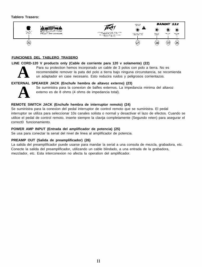
Tablero Trasero:
FUNCIONES DEL TABLERO TRASERO
LINE CORD-120 V products only (Cable de corriente para 120 v solamente) (22)
A Para su protection hemos incorporado un cable de 3 polos con polo a tierra. No esrecomendable remover la pata del polo a tierra bajo ninguna circunstancia, se recomiendaun adaptador en case necesario. Esto reducira ruidos y peligrosos corrientazos.
EXTERNAL SPEAKER JACK (Enchufe hembra de altavoz externo) (23)
A Se suministra para la conexion de bafles externos. La impedancia minima del altavozexterno es de 8 ohms (4 ohms de impedancia total).
REMOTE SWITCH JACK (Enchufe hembra de interruptor remoto) (24)Se suministra para la conexion del pedal interruptor de control remoto que se suministra. El pedalinterruptor se utiliza para seleccionar 10s canales solista o normal y desactivar el lazo de efectos. Cuando seutilice el pedal de control remoto, inserte siempre la clavija completamente (Segundo reten) para asegurar elcorrect0 funcionamiento.
POWER AMP INPUT (Entrada del amplificador de potencia) (25)Se usa para conectar la senal del nivel de linea al amplificador de potencia.
PREAMP OUT (Salida de preamplificador) (26)La salida del preamplificador puede usarse para mandar la serial a una consola de mezcla, grabadora, etc.Conecte la salida del preamplificador, utilizando un cable blindado, a una entrada de la grabadora,mezclador, etc. Esta interconexion no afecta la operation del amplificador.
11

Veuillez-vous rbfker au “front panel line art”situ6 dans la section en langue anglaise de ce manuel.
Felicitations pour votre achat du Bandit@ 112 TransTube nouvelle serie. Cet amplificateur, entierementnovateur, est le fruit d’annees de recherche sur I’emulation de tube a vide. La nouvelle conception dupreamplificateur s’appuie sur une technologie (brevet en instance) qui redefinit la distorsion de type tube etla generation d’harmoniques dans les amplificateurs a transistor.
Le nouveau circuit de ((Dynamique T>> (brevets egalement en instance) tree le phenomene si longtempsrecherche de compression de la puissance de tube. S’alliant aux circuits de resonance et de presence, ildonne la meilleure simulation d’amplificateur a tube a ce jour. Cet effet de compression est augmente endiminuant la commande ((Dynamique T j>, ce qui se traduit par une baisse du niveau de puissance emise parI’amplificateur.
Pour renforcer la performance du Bandit, une fiche de haut-parleur externe supplementaire Porte la puis-sance a 100 watts, tandis qu’une boucle d’effets, commutable par pedale, accroit la souplesse d’utilisation.
CARACTERISTIQUES DU PANNEAU AVANT
HIGH GAIN INPUT (Entrke haut gain) (1)Cette prise s’utilise avec la plupart des guitares electriques. Elle donne un gain superieur de 6 dB a I’entree“Low Gain”.
LOW GAIN INPUT (Entree faible gain) (2)Cette prise accepte les instruments a t&s haut niveau de sortie qui causeraient de la saturation (distorsion)sur I’entree “High Gain”. Si les deux entrees sont utilisees simultanement, les niveaux sont alors equivalents(“Low Gain”).
VOLUME (3)Controle le niveau de volume du canal “Clean”.
BRIGHT SWITCH (Sblecteur de brillance) (4)Accentue (6 dB) les frequences aigues. Pour activer, mettre le bouton en position “In”.
CHANNEL SELECT SWITCH (Sklecteur de canal) (5)Permet de selectionner les canaux “Lead” ou “Clean”. La position “In” du selecteur correspond au canal“Lead”. La position “Out” selectionne le canal “Clean”.
Remarque: La selection de canal peut aussi s’accomplir a distance a I’aide de la pedale-interrupteur. Pourque la selection a distance soit possible, le canal doit etre en position “In” (“Lead”).
LOW, MID, & HIGH EQ (Egalisation graves, moyennes et aigu&) (6)Reglages de tonalite passifs reglant frequences graves, moyennes et aigues du canal “Clean”.
PRE GAIN (7)Controle le niveau de volume a I’entree sur du canal “Lead”.
12

THRASH SWITCH (Commutateur anti-emballement) (8)Ajuste le registre moyen d’environ 20 dB.
GAIN SWITCH (Interrupteur de gain) (9)Hausse le gain global du systeme. Abaisser a la position “In” pour activer.
LOW, MID, & HIGH EQ (egalisation graves, moyennes et aigu&) (10)Reglages de tonalite passifs reglant frequences graves, moyennes et aigues du canal “Lead”.
POST GAIN (11)Commande le volume general du canal “Lead”. Le reglage final de niveau doit etre effect& apres avoirobtenu la sonorite desiree a I’aide des autres reglages.
REVERB LEVEL (Niveau de rhverbhation) (12)Controle le niveau de reverberation global.
EFFECTS SEND (Envoi d’effets) (13)Prise de sortie servant a fournir des signaux a des appareils externes de traitement de signal ou d’effets abas niveau.
EFFECTS RETURN (Retour d’effets) (14)Prise d’entree pour signaux provenant d’appareils externes de traitement de signal ou d’effets a bas niveau.
EFX LEVEL SWITCH (Commutateur de niveau d’effets) (15)Selectionne le niveau de fonctionnement de la boucle d’effets : -10 dBV (0,3 V RMS) en <sortie>> et 0 dBV(1 V RMS) en <<entree,,.
RESONANCE SWITCH (Commutateur de rhonance) (16)Utilise pour assurer I’accord precis de la gamme des basses frequences de I’enceinte du haut-parleur enfaisant varier le facteur d’amortissement de I’amplificateur entre deux reglages predetermines.
PRESENCE (Prksence) (17)Reglage de tonalite actif qui renforce les frequences extremes aigues (+6 dB).
TTM DYNAMICS CONTROL (Commande c<Dynamique T>j) (18)Regle le niveau de puissance de I’amplificateur de 10 a 100%. Lorsqu’il est regle en bas de plage, la simula-tion de compression de puissance est bien plus prononcee.
POWER LED (DEL tbmoin de mise sous tension) (19)S’allume lorsque I’ampli recoit I’alimentation CA.
POWER SWITCH (Interrupteur d’alimentation) (20)Mettre I’interrupteur en position “On”. La lampe temoin rouge (DEL) s’illumine indiquant que I’appareil estalimente en courant.
13

Panneau Arriere:
CARACTERISTIQUES DU PANNEAU ARRIlkRE
LINE CORD-120 V products only (Cordon d’alimentation pour appareils 120 V seulement) (22)
A Pour votre securite, nous avons incorpore un cable d’alimentation secteur a 3 fils avec mise-a-terre appropriee. II nest pas recommande d’enlever la broche de mise-a-terre en aucunecirconstance. S’il est necessaire d’utiliser I’equipement sans mise-a-terre appropriee, utilisezdes adaptateurs de mise-a-terre convenables. Une bonne mise-a-terre amoindrit le bruit defond et reduit grandement les risques de choc.
EXTERNAL SPEAKER JACK (Prise pour haut-parleur externe) (23)
A Sortie pour branchement d’une enceinte de haut-parleur separee. Impedance de haut-parleur externe minimale : 8 ohms (impedance totale de 4 ohms).
REMOTE SWITCH JACK (Prise pour interrupteur a distance) (24)Permet de brancher la pedale-interrupteur incluse. L’interrupteur au pied est utilise pour selectionner lescanaux “Normal” ou “Lead” et pour mettre hors circuit la boucle d’effets. Afin d’assurer un bonfonctionnement lors de I’utilisation de I’interrupteur au pied, inserez la fiche bien a fond (au second clic).
POWER AMP INPUT (Entree ampli de puissance) (25)Set-t a brancher un signal de niveau ligne a I’amplificateur de puissance.
PREAMP OUT (Sortie preampli) (26)La sortie preampli peut etre utilisee pour amener le signal a une table de mixage, un magnetophone, etc.Utilisez des cables blind& pour brancher la sortie du preampli a I’entree d’un magnetophone, d’unmelangeur, etc. Ce branchement n’affecte pas le fonctionnement de l’amplificateur.
14

Siehe Diagramm der Frontplatte im englischen Teil des Handbuchs.
Wir begluckwunschen Sie zum Erwerb dieses Verstarkers aus der neuen Bandit@ 112 Serie. Der neueBandit ist das Ergebnis langjahriger Forschungsarbeit auf dem Gebiet der Hochvakuumrohrenemulation.Dieser Vorverstarker wurde unter Zuhilfenahme einer zum Patent angemeldeten Technologie konstruiert, dierohrenahnliche Verzerrung und Oberwellenerzeugung in Festkbrperverstarkern neu definiert.
Der neue T.-Dynamik-Schaltungsaufbau - der such fur mehrere Patente angemeldet wurde - erzeugt dasfur Rohren typische Hochleistungskompressionsphanomen, nach dem bisher vergeblich gesucht wurde.Dazu kommt der Resonanz- und Prasenzschaltungsaufbau und das Ergebnis ist die wohl gelungensteRohrenverstarkersimulation, die man sich vorstellen kann. Der Kompressionseffekt wird verstarkt, wenn Siedie T.-Dynamik herunterregeln und somit den Ausgabepegel das Verstarkers vermindern.
Die Leistungsfahigkeit das Bandit wird durch eine externe Lautsprecherbuchse, die die Leistung auf 100Watt erhoht und eine durch FuOpedal steuerbare Effektschleife fur bessere Flexibilitat noch vergrdt3ert.
BESCHREIBUNG DER FRONTPLATTE
HIGH GAIN INPUT (Hijhen Gain-Eingsng) (1)Dieser Eingang kann fur die meisten elektrischen Gitarren verwendet werden. Er ist 6 dB empfindlicher alsder Low Gain Input.
LOW GAIN INPUT (Mittleren Gain-Eingting) (2)Dieser Eingang ist fur die lnstrumente vorgesehen, die ein besonders hohes Ausgangssignal erzeugen.Falls beide Eingange gleichzeitig benutzt werden, sind die Ausgangssignale gleich (beide sind dann LowGain).
VOLUME (3)Regelt den Pegel das “Clean”-Kanals.
BRIGHT SWITCH (4)Besorgt einen voreingestellten Schub (+6 dB) in den hohen Frequenzen. Zur Aktivierung den Knoph in die“In”-Position drucken.
CHANNEL SELECT SWITCH (Kanal-Wahl-Schalter) (5)Erlaubt die Auswahl das Lead-oder das “Clean”-Kanals. Die “In-Position das Schalters wahlt den Lead-Kanal, die “Out’‘-Position den “Clean”-Kanal an.
MERKE: Kanalwahl kann such mittels dem FernbedienungsfuOschalter ausgefuhrt werden. Dazu mu13 der“Channel”-Schalter sich in der “in” (lead) Position befinden.
LOW, MID, & HIGH EQ (Tiefen, Mittleren, und Hijhen Frequenzen) (6)Hierbei handelt es sich urn passive Klangregler, die tiefe, mittlere und hohe Frequenzen entsprechendregeln das Clean-Kanals.
PRE GAIN (7)Kontrolliert den Vorstufenpegel das Lead-Kanals.
15

THRASH SWITCH (Thrashschalter) (8)Andert den Mittelbereich urn etwa 20 dB.
GAIN SWITCH (9)Boostet die Gesamtlautstarke. Zum Einschalten auf die “In” - Position bringen.
LOW, MID, & HIGH EQ (Tiefen, Mittleren, und Hijhen Frequenzen) (10)Hierbei handelt es sich urn passive Klangregler, die tiefe, mittlere und hohe Frequenzen entsprechendregeln das Lead-Kanals.
POST GAIN (11)Kontrolliert den gesamten Lautstarke-pegel das Hauptkanals (Mastervolumen). Die endgijltigeLautstarkeregelung sollte vorgenommen werden, nachdem der gewiinschte Sound eingestellt ist.
REVERB LEVEL (Reverb-Pegel) (12)Regelt den Reverb-Pegel.
EFFECTS SEND (Effektausgang) (13)Ausgang fur Zuliefersignale zu externen niederohmigen Effekten oder Signal-Prozessoren.
EFFECTS RETURN (Effekteingang) (14)Eingang fur ruckfuhrende Signale von niederohmigen Effekten oder Signal-Prozessoren.
EFFECTS LEVEL SWITCH (Effects-pegelschalter) (15)Wahlt den Operationsbereich der Effektschleife aus: -10 dBV (0,3 V RMS), wenn der Schalter in der “out”-Position steht und 0 dBV (1 V RMS), wenn in der “in’‘-Position.
RESONANCE SWITCH (Resonanzschalter) (16)Damit wird der tiefe Frequenzbereich das Lautsprechergeh&rses feinabgestimmt, indem derDampfungsfaktor das Verstarkers zwischen zwei Vorgaben variiert wird.
PRESENCE (17)Eine aktive Tonkontrolle, welche die extrem hohen Frequenzen urn 6 dB boostet (anhebt).
TTM DYNAMICS CONTROL (T-Dynamikregler) (18)Regelt den Leistungspegel das Verstarkers von 10% bis 100% Leistung. Bei den niedrigeren Einstellungenist die Simulation der Leistungskompression sehr viel betonter.
POWER LED (Betriebsanzeige) (19)Zeigt die eingeschaltete Netzspannung an.
POWER SWITCH (Netzschalter) (20)Bringen Sie den Schalter auf die ON-Position. Die rote Kontrollampe (LED) leuchtet und zeigt an, dat3 dasGet-at eingeschaltet ist.
16
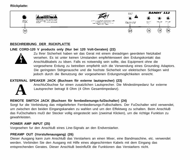
Riickplatte:
BESCHREIBUNG DER RiiCKPLATTE
LINE CORD-120 V products only (Nur bei 120 Volt-Geraten) (22)
A Zu lhrer Sicherheit haben wir das Gerat mit einem dreiadrigen geerdeten Netzkabelversehen. Es ist unter keinen Umstanden empfehlenswert den Erdungskontakt dasAnschluBkabels zu Idsen. Falls es notwendig sein sollte, das Equipment ohne dievorgesehene Erdung zu betreiben empfiehlt sich die Verwendung eines Grounding Adaptors.Die geringsten Stdrgerausche und die hochste Sicherheit vor elektrischen Schlagen wirdjedoch durch die Benutzung der vorgesehenen Erdungsmoglichkeiten erreicht.
EXTERNAL SPEAKER JACK (Buchsen fiir externe lautsprecher) (23)
A AnschluObuchse fur einen zusatzlichen Lautsprecher. Die Mindestimpedanz fur externeLautsprecher betragt 8 Ohm (4 Ohm Gesamtimpedanz).
REMOTE SWITCH JACK (Buchsen fiir fernbedienungs-ful3schalter) (24)Sorgt fur die Verbindung das mitgelieferten Fernbedienungs-FuBschalters. Der FuOschalter wird verwendet,urn zwischen den beiden Eingangskanalen zu wahlen und urn den Effektweg zu schalten. Beim AnschluBdas FuOschalters mul3 der Stecker vollig eingesteckt sein (zweimal Klicken), urn die richtige Funktion zugewahrleisten.
POWER AMP INPUT (25)Vorgesehen fur den AnschluB eines Line-Signals an den Endverstarker.
PREAMP OUT (Vorstufenausgang) (26)Dieser Ausgang kann zum AnschluB das Verstarkers an einen Mixer, eine Bandmaschine, etc. verwendetwerden. Verbinden Sie den Ausgang mit Hilfe eines abgeschirmten Kabels mit dem Eingang dasentsprechenden Gerates. Dieser AnschluB beeinfluf3t die Funktionen das Verstarkers nicht.

For further information on other Peavey products,ask your Authorized Peavey Dealer for the
appropriate Peavey catalog/publication.
Bass GuitarsGuitars
Bass AmplificationGuitar Amplification
Sound Reinforcement EnclosuresMicrophonesKeyboards
DJLighting
Mixers, Powered/Non-PoweredAccessories/CablesEffects Processors
Axcess’” WearThe Peavey Beat“”
Monitor@ MagazineKey Issues’”Low Down’”
PM’” Magazine

THIS LIMITED WARRANTY VALID ONLY WHEN PURCHASED AND REGISTERED IN THE UNITED STATES OR CANADA. ALL EXPORTED PRODUCTSARE SUBJECT TO WARRANTY AND SERVICES TO BE SPECIFIED AND PROVIDED BY THE AUTHORIZED DISTRIBUTOR FOR EACH COUNTRY.Ces clauses de garantie ne sont vaiables qu’aux Etats-Unis et au Canada. Dans tour les autres pays, les clauses de garantie et de maintenance sontfixees par le distributeur national et assuree par lul seion la legislation envigueur. l 9 Diese Garantie ist nur in den USA and Kanada gultig. Alle Export-Produkte sind der Garantie und dem Service des lmporteurs des jewelligen Landes unterworfen. l l Esta garantia es valida solamente cuando elproduct0 es comprado en E.U. continentales o en Canada. Todos 10s productos que Sean comprados en el extranjero, estan sujetos a las garantias yservicio que cada distribuidor autorizado determine y ofrezca en 10s diferentes paises.
PEAVEY ONE-YEAR LIMITEDWARRANTY/REMEDY
PEAVEY ELECTRONICS CORPORATION (“PEAVEY”) warrants thus product, EXCEPT for covers, footswitches, patchcords, tubes and meters, to be free fromdefects in matenal and workmanship for a period of one (1) year from date of purchase, PROVIDED, however, that thus limited warranty is extended only to theorigrnal retail purchaser and is subject to the conditions, exclusions, and limitations hereinafter set forth:
PEAVEY 90-DAY LIMITED WARRANTY ON TUBES AND METERSIf this product contains tubes or meters, Peavey warrants the tubes or meters contained in the product to be free from defects in material and workmanshrp for
a period of ninety (90) days from date of purchase; PROVIDED, however, that this limited warranty IS extended only to the original retail purchaser and IS alsosubject to the conditions, exclusions, and limitations hereinafter set forth.
CONDITIONS, EXCLUSIONS, AND LIMITATIONS OF LIMITED WARRANTIESThese limited warranties shall be void and of no effect, if:a. The first purchase of the product is for the purpose of resale; orb. The original retail purchase is not made from an AUTHORIZED PEAVEY DEALER; orc. The product has been damaged by accident or unreasonable use, neglect, improper service or maintenance, or other causes not arising out of defects in
material or workmanship; ord. The serial number affixed to the product is altered, defaced, or removed.In the event of a defect in material and/or workmanship covered by this limited warranty, Peavey will:a. In the case of tubes or meters, replace the defective component without charge.b. In other covered cases (i.e., cases lnvolvlng anything other than covers, footswrtches, patchcords, tubes or meters), repair the defect In material or
workmanship or replace the product, at Peavey’s option; and provided, however, that, in any case, all costs of shipping, if necessary, are paid by you, thepurchaser.
THE WARRANTY REGISTRATION CARD SHOULD BE ACCURATELY COMPLETED AND MAILED TO AND RECEIVED BY PEAVEY WITHIN FOURTEEN (14)DAYS FROM THE DATE OF YOUR PURCHASE.In order to obtain service under these warranties, you must:a. Bring the defective item to any PEAVEY AUTHORIZED DEALER or AUTHORIZED PEAVEY SERVICE CENTER and present therewith the ORIGINAL
PROOF OF PURCHASE supplied to YOU by the AUTHORIZED PEAVEY DEALER in connection with your purchase from him of this product,If the DEALER or SERVICE CENTER is unable to provide the necessary warranty service you will be directed to the nearest other PEAVEY AUTHORIZEDDEALER or AUTHORIZED PEAVEY SERVICE CENTER which can provide such service.
ORb. Ship the defective item, prepaid, to:
PEAVEY ELECTRONICS CORPORATIONInternational Service Center
326 Hwy. 11 & 80 EastMeridian, MS 39301
including therewith a complete, detailed description of the problem, together with a legible copy of the ongrnal PROOF OF PURCHASE and a complete returnaddress. Upon Peavey’s receipt of these items: If the defect is remedial under these limited warranties and the other terms and conditions expressed hereinhave been complied with, Peavey will provide the necessary warranty service to repair or replace the product and will return it, FREIGHT COLLECT, to you,the purchaser.
Peavey’s liability to the purchaser for damages from any cause whatsoever and regardless of the form of action, including negligence, is limited to the actualdamages up to the greater of $500.00 or an amount equal to the purchase price of the product that caused the damage or that IS the subject of or is directly relatedto the cause of action. Such purchase price will be that in effect for the specific product when the cause of action arose. This limitation of liability will not apply toclaims for personal injury or damage to real property or tangible personal property allegedly caused by Peavey’s negligence. Peavey does not assume liability forpersonal injury or property damage arising out of or caused by a non-Peavey alteration or attachment, nor does Peavey assume any responsibility for damage tointerconnected non-Peavey equipment that may result from the normal functioning and maintenance of the Peavey equipment.
UNDER NO CIRCUMSTANCES WILL PEAVEY BE LIABLE FOR ANY LOST PROFITS, LOST SAVINGS, ANY INCIDENTAL DAMAGES, OR ANYCONSEQUENTIAL DAMAGES ARISING OUT OF THE USE OR INABILITY TO USE THE PRODUCT, EVEN IF PEAVEY HAS BEEN ADVISED OF THEPOSSIBILITY OF SUCH DAMAGES.
THESE LIMITED WARRANTIES ARE IN LIEU OF ANY AND ALL WARRANTIES, EXPRESSED OR IMPLIED, INCLUDING, BUT NOT LIMITED TO, THEIMPLIED WARRANTIES OF MERCHANTABILITY AND FITNESS FOR A PARTICULAR USE; PROVIDED, HOWEVER, THAT IF THE OTHER TERMS ANDCONDITIONS NECESSARY TO THE EXISTENCE OF THE EXPRESSED, LIMITE;: WARRANTIES, AS HEREINABOVE STATED, HAVE BEEN COMPLIEDWITH, IMPLIED WARRANTIES ARE NOT DISCLAIMED DURING THE APPLICABLE ONE-YEAR OR NINETY-DAY PERIOD FROM DATE OF PURCHASE OFTHIS PRODUCT.
SOME STATES DO NOT ALLOW LIMITATION ON HOW LONG AN IMPLIED WARRANTY LASTS, OR THE EXCLUSION OR LIMITATION OF INCIDENTALOR CONSEQUENTIAL DAMAGES, SO THE ABOVE LIMITATIONS OR EXCLUSIONS MAY NOT APPLY TO YOU. THESE LIMITED WARRANTIES GIVE YOUSPECIFIC LEGAL RIGHTS, AND YOU MAY ALSO HAVE OTHER RIGHTS WHICH MAY VARY FROM STATE TO STATE.
THESE LIMITED WARRANTIES ARE THE ONLY EXPRESSED WARRANTIES ON THIS PRODUCT, AND NO OTHER STATEMENT, REPRESENTATION,WARRANTY, OR AGREEMENT BY ANY PERSON SHALL BE VALID OR BINDING UPON PEAVEY.
In the event of any modificatron or disclaimer of expressed or implied warranties, or any limitation of remedies, contained herein conflicts with applicable law,then such modification, disclaimer or limitation, as the case may be, shall be deemed to be modified to the extent necessary to comply with such law.
Your remedies for breach of these warranties are limited to those remedies provided herein and Peavey Electronics Corporation gives this lrmrted warranty onlywith respect to equipment purchased In the United States of America.
INSTRUCTIONS -WARRANTY REGISTRATION CARD1. Mail the completed WARRANTY REGISTRATION CARD to:
PEAVEY ELECTRONICS CORPORATIONP.O. BOX 2898
Meridian, MS 39302-2898a. Keep the PROOF OF PURCHASE. In the event warranty service is required during the warranty period, you will need this document. There will be no
identification card issued by Peavey Electronics Corporation.2. IMPORTANCE OF WARRANTY REGISTRATION CARDS AND NOTIFICATION OF CHANGES OF ADDRESSES:
a. Completion and mailing of WARRANTY REGISTRATION CARDS - Should notification become necessary for any condition that may require correction,the REGISTRATION CARD will help ensure that you are contacted and properly notified.
b. Notice of address changes - If you move from the address shown on the WARRANTY REGISTRATION CARD, you should notify Peavey of the change ofaddress so as to facilitate your receipt of any bulletins or other forms of notification which may become necessary in connectron with any condition that mayrequire dissemination of information or correctron.
3. You may contact Peavey directly by telephoning (601) 483-5365.

IMPORTANT SAFETY INSTRUCTIONSWARNING: When using electric products, basic cautions should always be followed, including the following.
1.
2.
3.
4.
5.
6.
7.
8.
9.
10.
11.
12.
13.
14.
15.
16.
17.
18.
Read all safety and operating instructions before using this product.
All safety and operating instructions should be retained for future reference.
Obey all cautions in the operating instructions and on the back of the unit.
All operating instructions should be followed.
This product should not be used near water, i.e., a bathtub, sink, swimming pool, wet basement, etc.
This product should be located so that its position does not interfere with its proper ventilation. It should not be placed flat against awall or placed in a built-in enclosure that will impede the flow of cooling air.
This product should not be placed near a source of heat such as a stove, radiator, or another heat producing amplifier.
Connect only to a power supply of the type marked on the unit adjacent to the power supply cord.
Never break off the ground pin on the power supply cord. For more information on grounding, write for our free booklet “ShockHazard and Grounding.”
Power supply cords should always be handled carefully. Never walk or place equipment on power supply cords. Periodically checkcords for cuts or signs of stress, especially at the plug and the point where the cord exits the unit.
The power supply cord should be unplugged when the unit is to be unused for long periods of time.
If this product is to be mounted in an equipment rack, rear support should be provided.
Metal parts can be cleaned with a damp rag. The vinyl covering used on some units can be cleaned with a damp rag or an ammonia-based household cleaner if necessary. Disconnect unit from power supply before cleaning.
Care should be taken so that objects do not fall and liquids are not spilled into the unit through the ventilation holes or any otheropenings.
This unit should be checked by a qualified service technician if:a. The power supply cord or plug has been damaged.b. Anything has fallen or been spilled into the unit.C. The unit does not operate correctly.d. The unit has been dropped or the enclosure damaged.
The user should not attempt to service this equipment. All service work should be done by a qualified service technician.
This product should be used only with a cart or stand that is recommended by Peavey Electronics.
Exposure to extremely high noise levels may cause a permanent hearing loss. Individuals vary considerably in susceptibility to noiseinduced hearing loss, but nearly everyone will lose some hearing if exposed to sufficiently intense noise for a sufficient time.The U.S. Government’s Occupational Safety and Health Administration (OSHA) has specified the following permissible noise levelexposures.
Duration Per Day In Hours Sound Level dBA, Slow Response8 906 924 953 972 100
1 112 1021 105
112 1101/4 or less 115
According to OSHA, any exposure in excess of the above permissible limits could result in some hearing loss.Ear plugs or protectors in the ear canals or over the ears must be worn when operating this amplification system in order to prevent apermanent hearing loss if exposure is in excess of the limits as set forth above. To ensure against potentially dangerous exposure to highsound pressure levels, it is recommended that all persons exposed to equipment capable of producing high sound pressure levels such asthis amplification system be protected by hearing protectors while this unit is in operation.
SAVE THESE INSTRUCTIONS!
Features and specifications subject to change without notice. APeavey Electronics Corporation 711 A Street / Meridian, MS 39301 / U.S.A. / (601) 483-5365 / Fax 486-1278
01995 #80302302