Embed Size (px)
Citation preview

TECH SHEETPEM® REF/ TESTING CLINCH PERFORMANCE
JULY 2019
Corporate Headquarters: 5190 Old Easton Rd. Danboro, PA 18916 • www.pemnet.com© 2019 Page 1
A self-clinching fastener’s performance can be divided into two major types.
The first is self-clinching performance. Included here are several measures of the strength of the attachment between the fastener and the host panel. The second, is fastening performance and includes several measures of the load carrying strength of the fastener.
It is the self-clinching performance that will be the focus of this Tech Sheet. Although the primary focus below is on self clinching, the basic principals are also applicable to other means of fastener captivation such as broaching, surface mounting and resistance welding.
Self Clinching Performance
Self-clinching performance includes three primary measures of mechanical strength. These include push-out, torque-out, and side load. Thread fit will also be examined as a dimensional check as it relates to these mechanical strength measures.
Factors effecting self-clinching performance-Several factors (below) affect self-clinching performance and their values must be correct in order to achieve optimum performance. If any one of these factors is not within the required range, performance can be reduced.
1. Panel hardness must be below specified maximum2. Holes in panel must be of proper size and away from edges and bends 3. Panel must meet minimum thickness requirements for specific fastener.4. Panel material must have adequate ductility5. Fastener must be properly installed (squeezing type force-not hammer blows) and fully
installed without being over installed6. Fastener clinch feature must be dimensionally correct7. Fastener must be above specified minimum hardness8. Fastener must not have been embrittled by any acid cleaning or electroplating
Knowing the number of factors involved helps us understand that there can be instances when all requirements are (knowingly or unknowingly) not being met. In these cases testing may be necessary to further determine if performance has been compromised.
SUBJECT: TESTING CLINCH PERFORMANCE OF SELF-CLINCHING FASTENERS

TECH SHEETPEM® REF/ TESTING CLINCH PERFORMANCE
JULY 2019
Corporate Headquarters: 5190 Old Easton Rd. Danboro, PA 18916 • www.pemnet.com© 2019 Page 2
Measures of PerformanceAs mentioned earlier, the primary measures of self-clinching performance include push-out, torque-out, and side load. Let us examine each one in detail.
Push-out is a measure of the axial holding power of the clinch feature. Push-out performanceis applicable to all self clinching fasteners, including both threaded and non-threaded. Severalimportant facts about push-out are: • By definition, applied force is in the direction opposite the installation force. • The panel is supported by a bushing with a nominal inside diameter .062”/1.5mm larger
than the largest diameter or across corners dimension of the fastener • Units are lbs. for parts with Unified threads and N or kN for parts with metric threads • PEM® catalog bulletins typically show values for steel panels and for aluminum panels
During the installation process the displacer feature (head or knurl) on the fastener is imbeddedinto the panel. This process forces the displaced material to “cold flow” into the undercut of thefastener permanently attaching it to the sheet. Then, in order to push the fastener out of the sheet, one must overcome the holding forces of the imbedded knurl and the displaced panel material in the undercut. Typically the material in the undercut will fail in one of two ways. In soft aluminum, the panel material will shear, leaving an annular ring of panel material in the undercut of the pushed out fastener. In cold rolled steel, the panel material will bend out of the way leaving no panel material in the undercut of the pushed out fastener. There is a third failure mode seen more rarely; the fastener shank can fracture leaving the displaced panel material essentially intact. This mode is unique to nut products and usually only occurs in higher hardness panels.
In a typical self-clinching installation the undercut is filled or nearly filled with panel material allowing the panel material to make contact with the back taper of the shank. In this case, the force to dislodge the displacer together with the force required to clear the panel material from the undercut combine to create optimum push-out performance. A force Vs distance curve for this situation is shown as curve A in Figure 1. If hardness differential between the fastener and panel is not sufficient, the displacer will deform resulting in the undercut not being completely filled. In this case the force to clear the panel material from the undercut will peak after the force to dislodge the imbedded displacer. The result is lower push-out. A force Vs distance curve for this situation is shown as curve B in Figure 1. Note the different curve shape and the drop in force after the first peak. Force Vs distance curves generated during a pushout test are a useful diagnostic tool when evaluating clinch feature performance. Figure 1

TECH SHEETPEM® REF/ TESTING CLINCH PERFORMANCE
JULY 2019
Corporate Headquarters: 5190 Old Easton Rd. Danboro, PA 18916 • www.pemnet.com© 2019 Page 3
A typical test set-up for push-out test is shown for nut product in Figure 2 and for stud product in Figure 3.
Torque-out is a measure of the torsional holding power of the clinch feature. Torque-outperformance is more applicable to threaded fasteners than it is to non-threaded fasteners, but canbe applied to those non-threaded fasteners that utilize a non-round displacer. Several importantfacts about torque-out are: • By definition, applied torque is a pure torque in that the applied torque must not induce
any axial load between the fastener and the panel • For practical reasons torque is usually applied in the direction of screw tightening, but
can be applied in either direction • Panel is restrained from rotation by any appropriate means, such as holding it in a vice • Units are in-lb. for parts with Unified threads and N.m for parts with metric threads • PEM® Catalog bulletins typically show values for steel panels and for aluminum panels
During the installation process the displacer feature on the fastener was imbedded into thepanel. For threaded fasteners the displacer always has a non-round shape which provides torqueresistance.
There are two primary modes of failure seen during a torque-out test. In the first, the displacershears panel material out of its way and rotates in the panel with little or no axial movement. Thisfailure mode is typical for soft aluminum panels. The second, described as “cam-out” occurswhen angled portions of the displacer exert an axial force in the push-out direction causing someaxial movement of the fastener in the sheet. Typically the panel material does not shear, butbends or otherwise displaces out of the path of the rotating displacer. There may also be somedeformation of the displacer. The purest example of this failure mode is a precipitation hardeningfastener in a 300 series stainless steel panel. Pure “cam-out” failure are not common with manypopular panel and fastener combinations showing a failure mode that is some combination of thetwo modes with both axial displacement and some shearing of panel material.
Figure 2 Figure 3

TECH SHEETPEM® REF/ TESTING CLINCH PERFORMANCE
JULY 2019
Corporate Headquarters: 5190 Old Easton Rd. Danboro, PA 18916 • www.pemnet.com© 2019 Page 4
A typical test set-up for torque-out testing is shown for nut product in Figure 4a and Figure 4b and for stud product in Figure 5. Note that in all cases the applied torque is transmitted by the externally threaded member. For externally threaded product the torsional strength of the thread is determined by the product and may be the limiting factor for torque out. This is especially true for smaller thread sizes.
For internally threaded product, torque-out testing is typically done with a screw as shown inFigure 4a. With this method the torque is also limited by the torsional strength of the test screw.To minimize the effect of screw strength, PennEngineering uses test screw strength levels of180 ksi for unified and Property Class 12.9 for metric. However, even these high strength levelscrews typically fail in oversized body standoffs such as thread codes 6440 or 3.5M3. BecausePennEngineering’s policy is to publish clinch performance based on body size, not thread size,it may not be possible to achieve published values of torque-out for these products when testedas shown in Figure 4a because of screw failures. When this happens, the product can be testedwith a screw extractor as shown in figure 4b. This usually assures that the published value willbe achieved and the failure mode will be the clinch feature, not the test screw.
Figure 4aFigure 4b
Figure 5
TECH SHEETPEM® REF/ TESTING CLINCH PERFORMANCE
JULY 2019
Corporate Headquarters: 5190 Old Easton Rd. Danboro, PA 18916 • www.pemnet.com© 2019 Page 5
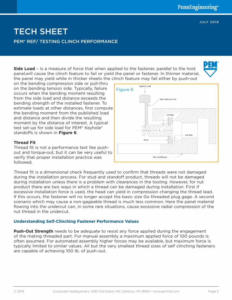
Side Load – Is a measure of force that when applied to the fastener, parallel to the host panel,will cause the clinch feature to fail or yield the panel or fastener. In thinner material, the panel may yield while in thicker sheets the clinch feature may fail either by push-out on the bending compression side or pull-thru on the bending tension side. Typically, failure occurs when the bending moment resulting from the side load and distance exceeds the bending strength of the installed fastener. To estimate loads at other distances, first compute the bending moment from the published load and distance and then divide the resulting moment by the distance of interest. A typical test set-up for side load for PEM® Keyhole® standoffs is shown in Figure 6.
Thread FitThread fit is not a performance test like push-out and torque-out, but it can be very useful toverify that proper installation practice was followed.
Thread fit is a dimensional check frequently used to confirm that threads were not damagedduring the installation process. For stud and standoff product, threads will not be damagedduring installation unless there is a problem with clearances in the tooling. However, for nutproduct there are two ways in which a thread can be damaged during installation. First ifexcessive installation force is used, the head can yield in compression changing the thread lead.If this occurs, the fastener will no longer accept the basic size Go threaded plug gage. A secondscenario which may cause a non-gageable thread is much less common. Here the panel materialflowing into the undercut can, in some rare situations, cause excessive radial compression of thenut thread in the undercut.
Understanding Self-Clinching Fastener Performance Values
Push-Out Strength needs to be adequate to resist any force applied during the engagementof the mating threaded part. For manual assembly a maximum applied force of 100 pounds isoften assumed. For automated assembly higher forces may be available, but maximum force istypically limited to similar values. All but the very smallest thread sizes of self clinching fastenersare capable of achieving 100 lb. of push-out.
Figure 6

TECH SHEETPEM® REF/ TESTING CLINCH PERFORMANCE
JULY 2019
Corporate Headquarters: 5190 Old Easton Rd. Danboro, PA 18916 • www.pemnet.com© 2019 Page 6
Torque-Out Strength needs to be adequate to resist the highest torque that the fastener will see in usage. There is a common misconception that 100% of the tightening torque applied to the mating threaded component is applied to the self-clinching fastener. This is not the case. A threaded connection is at best about 15% efficient, meaning that at least 85 % of the tightening torque is consumed by friction. This friction is divided nearly equally between the mating threads and the loaded face of the turned member. The turned member interface is the loaded face of the nut in the case of a self-clinching stud and the underside of the screw head in the case of a selfclinching nut. If we assume that 40 % of the total torque is consumed by friction in the interface at the turned member, then the self clinching fastener will never see more than 60% percent of the applied tightening torque during normal assembly.
During normal assembly the clamp load rises with the applied torque, increasing the torsionalstrength of the fastener in the panel. These two factors (60% torque and increased torque-outwith clamp load present) lead us to the rule of thumb that tightening torque for normal assemblycan be as high as two times the torque-out strength of the self-clinching fastener. There is onesignificant exception, in the rare event of cross threading the self-clinching fastener could see100% of the specified tightening torque.
Side Load Strength for a clinch fastener is usually only a consideration with standoff product.Side load strength must be adequate to resist the maximum side load that will be applied. Thedifficulty is often in estimating the applied side load. Experience has shown that many side loadrequirements are driven by vibration test requirements. In these cases PennEngineering canassist designers by considering the total mass suspended by the standoffs and the vibrationrequirement in “g” units (acceleration of gravity). If side load data is not available for the standoffsize and length in question, it usually can be estimated based on available data and theoreticalrelationships.
This TechSheet addresses many common aspects of self clinching fastener testing, but can not address all issues. For test issues not addressed here, or for any technical issues relative to self-clinching fasteners or other PennEngineering fastening products please email [email protected]