Embed Size (px)
Citation preview
PDX-089T-5A-512 / PDX-089T-8A-512
PDX-089T-5A / PDX-089T-8A
Vortex86DX Panel PC
with 8.9” TFT LCD
User’s Manual
(Revision 1.0A)
ii
Copyright The information in this manual is subject to change without notice for continuous improvement in the product. All rights are reserved. The manufacturer assumes no responsibility for any inaccuracies that may be contained in this document. And makes no commitment to update or to keep current the information contained in this manual. No part of this manual may be reproduced, copied, translated or transmitted, in whole or in part, in any form or by any means without the prior written permission of the manufacturer. ©Copyright 2009. Manual No. IUMPDX089-01 Ver.1.0A December, 2009
Trademarks Acknowledgment Vortex86DX™ is the registered trademark of the manufacturer. Other brand names or product names appearing in this document are the properties and registered trademarks of their respective owners. All names mentioned herewith are served for identification purpose only.
iii
Safety Information ♦ Read these Safety instructions carefully. ♦ Make sure the voltage of the power source is correct before connecting the equipment to
the power outlet. ♦ Do not expose your Panel PC to rain or moisture, in order to prevent shock and fire
hazard. ♦ Keep PDX-089T away from humidity. ♦ Do not open the cabinet to avoid electrical shock. Refer to your nearest dealer for
qualified personnel servicing. ♦ Never touch un-insulated terminals or wire unless your power adaptor is disconnected. ♦ Locate your Panel PC as close as possible to the socket outline for easy access and to
avoid force caused by entangling of your arms with surrounding cables from the Panel PC.
♦ USB connectors are not supplied with Limited Power Sources. ♦ If the equipment is not used for a long time, disconnect it from the power source to avoid
damage by transient overvoltage.
DO NOT ATTEMPT TO OPEN OR TO DISASSEMBLE THE CHASSIS (ENCASING) OF THIS PRODUCT. PLEASE CONTACT YOUR DEALER FOR
SERVICING FROM QUALIFIED TECHNICIAN.
T a b l e o f C o n t e n t s
T a b l e o f C o n t e n t s .............................................................iv C h a p t e r 1 General Information..…………………………………1
1.1 Product Description ................................................ 1 1.2 Product Specifications............................................ 2 1.3 Product Dimension..........................................4 1.4 Ordering Information .............................................. 5 1.5 Packing List ............................................................ 5
C h a p t e r 2 System Installation................................................. 6
2.1 CPU Board Outline................................................. 6 2.2 Connector Summary .............................................. 8 2.3 Connector Pin Assignments ................................... 9 2.4 External I/O Overview .......................................... 12 2.5 External I/O Pin Assignment................................. 13 2.6 System Mapping................................................... 15 2.7 Watchdog Timver ................................................. 18
C h a p t e r 3 Driver Installation…..………………………………..19
3.1 PDX-089T Development Note .............................. 20 3.2 BIOS Defaul Setting ............................................. 21
Warranty............................................................................................ 22

v
This page is blank
PDX-089T Vortex86DX™ Panel PC with 8.9” WSVGA TFT LCD 1
C h a p t e r 1
General Information
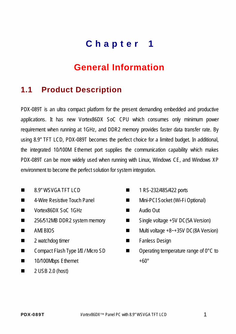
1.1 Product Description
PDX-089T is an ultra compact platform for the present demanding embedded and productive
applications. It has new Vortex86DX SoC CPU which consumes only minimum power
requirement when running at 1GHz, and DDR2 memory provides faster data transfer rate. By
using 8.9” TFT LCD, PDX-089T becomes the perfect choice for a limited budget. In additional,
the integrated 10/100M Ethernet port supplies the communication capability which makes
PDX-089T can be more widely used when running with Linux, Windows CE, and Windows XP
environment to become the perfect solution for system integration.
8.9” WSVGA TFT LCD
4-Wire Resistive Touch Panel
Vortex86DX SoC 1GHz
256/512MB DDR2 system memory
AMI BIOS
2 watchdog timer
Compact Flash Type I/II / Micro SD
10/100Mbps Ethernet
2 USB 2.0 (host)
1 RS-232/485/422 ports
Mini-PCI Socket (Wi-Fi Optional)
Audio Out
Single voltage +5V DC(5A Version)
Multi voltage +8~+35V DC(8A Version)
Fanless Design
Operating temperature range of 0°C to
+60°
PDX-089T Vortex86DX™ Panel PC with 8.9” WSVGA TFT LCD 2
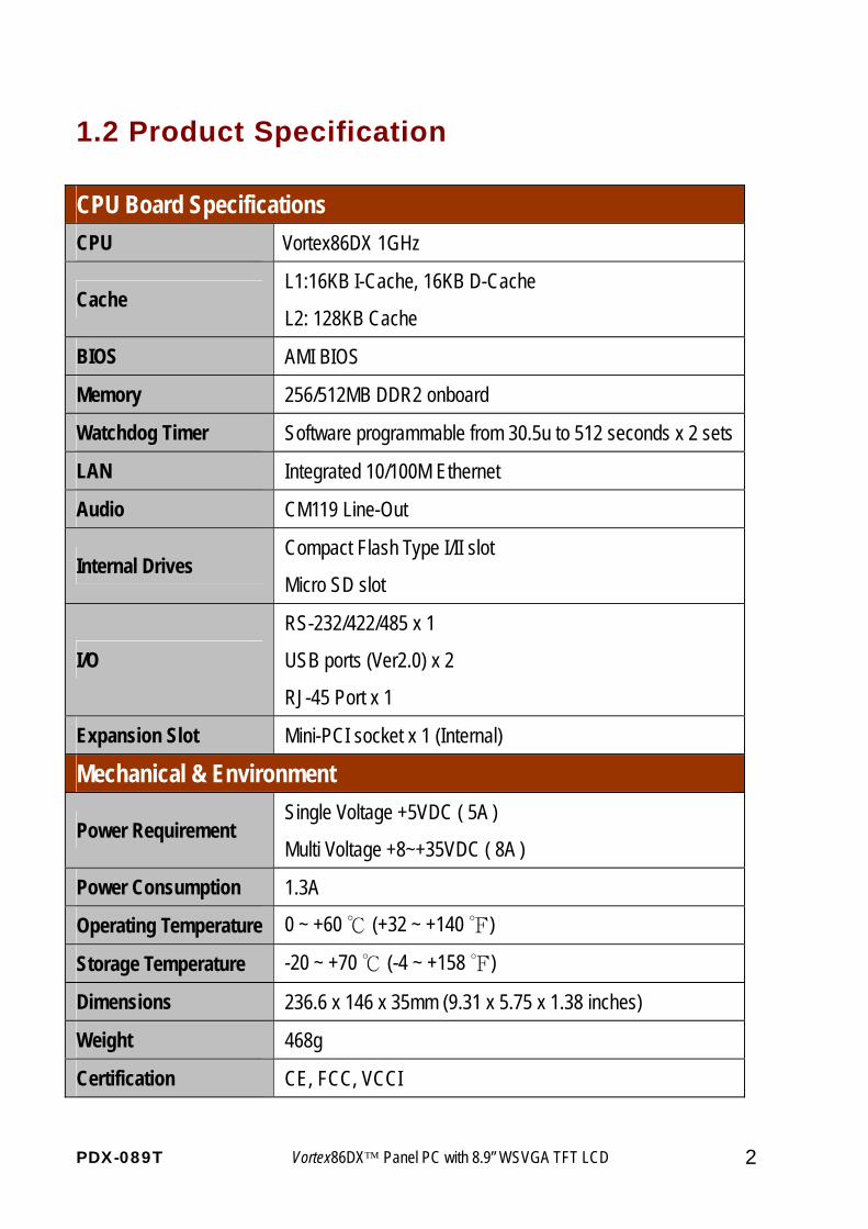
1.2 Product Specification CPU Board Specifications CPU Vortex86DX 1GHz
Cache L1:16KB I-Cache, 16KB D-Cache
L2: 128KB Cache
BIOS AMI BIOS
Memory 256/512MB DDR2 onboard
Watchdog Timer Software programmable from 30.5u to 512 seconds x 2 sets
LAN Integrated 10/100M Ethernet
Audio CM119 Line-Out
Internal Drives Compact Flash Type I/II slot
Micro SD slot
I/O
RS-232/422/485 x 1
USB ports (Ver2.0) x 2
RJ-45 Port x 1
Expansion Slot Mini-PCI socket x 1 (Internal)
Mechanical & Environment
Power Requirement Single Voltage +5VDC ( 5A )
Multi Voltage +8~+35VDC ( 8A )
Power Consumption 1.3A
Operating Temperature 0 ~ +60 ℃ (+32 ~ +140 ℉)
Storage Temperature -20 ~ +70 ℃ (-4 ~ +158 ℉)
Dimensions 236.6 x 146 x 35mm (9.31 x 5.75 x 1.38 inches)
Weight 468g
Certification CE, FCC, VCCI
PDX-089T Vortex86DX™ Panel PC with 8.9” WSVGA TFT LCD 3
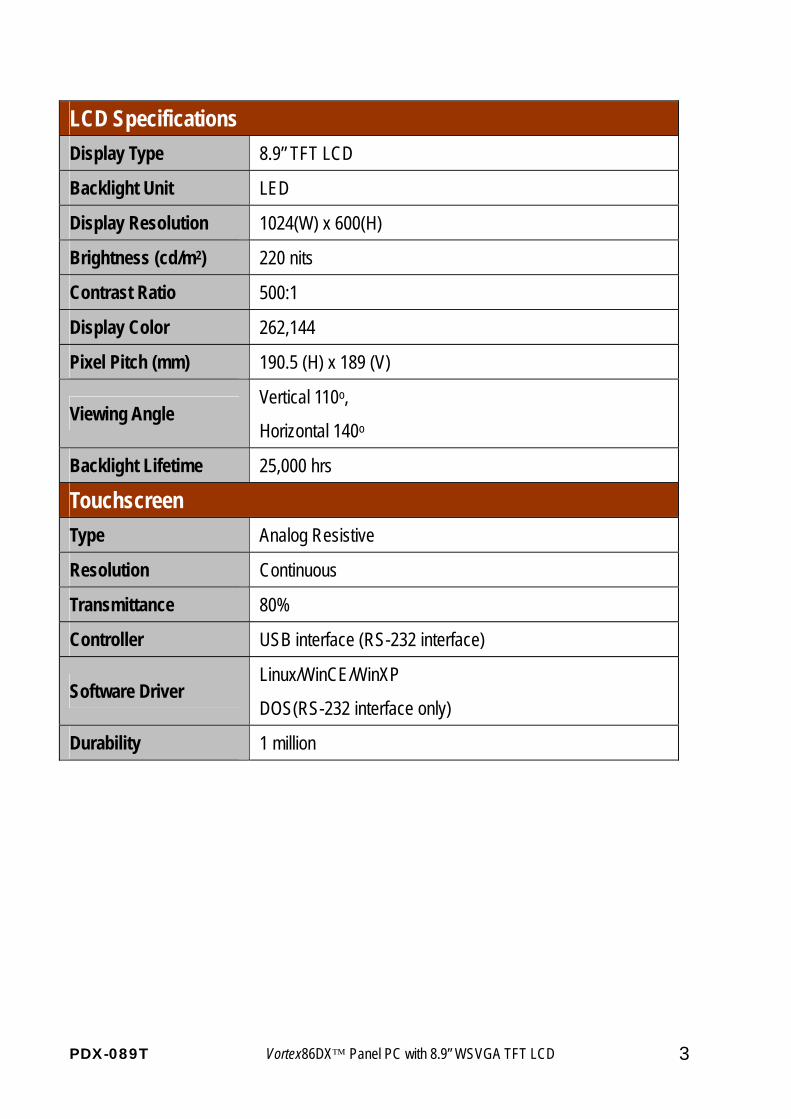
LCD Specifications Display Type 8.9” TFT LCD
Backlight Unit LED
Display Resolution 1024(W) x 600(H)
Brightness (cd/m2) 220 nits
Contrast Ratio 500:1
Display Color 262,144
Pixel Pitch (mm) 190.5 (H) x 189 (V)
Viewing Angle Vertical 110o,
Horizontal 140o
Backlight Lifetime 25,000 hrs
Touchscreen Type Analog Resistive
Resolution Continuous
Transmittance 80%
Controller USB interface (RS-232 interface)
Software Driver Linux/WinCE/WinXP
DOS(RS-232 interface only)
Durability 1 million
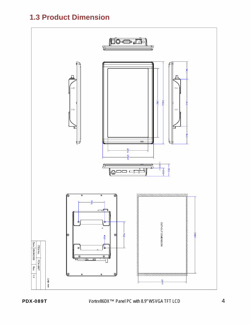
1.3 Product Dimension
PDX-089T Vortex86DX™ Panel PC with 8.9” WSVGA TFT LCD 4
PDX-089T Vortex86DX™ Panel PC with 8.9” WSVGA TFT LCD 5
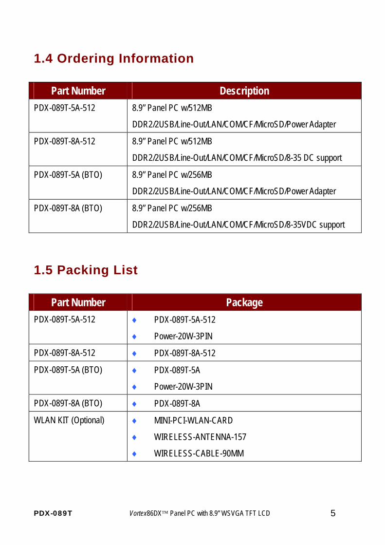
1.4 Ordering Information
Part Number Description PDX-089T-5A-512 8.9” Panel PC w/512MB
DDR2/2USB/Line-Out/LAN/COM/CF/MicroSD/Power Adapter
PDX-089T-8A-512 8.9” Panel PC w/512MB
DDR2/2USB/Line-Out/LAN/COM/CF/MicroSD/8-35 DC support
PDX-089T-5A (BTO) 8.9” Panel PC w/256MB
DDR2/2USB/Line-Out/LAN/COM/CF/MicroSD/Power Adapter
PDX-089T-8A (BTO) 8.9” Panel PC w/256MB
DDR2/2USB/Line-Out/LAN/COM/CF/MicroSD/8-35VDC support
1.5 Packing List
Part Number Package PDX-089T-5A-512 ♦ PDX-089T-5A-512
♦ Power-20W-3PIN
PDX-089T-8A-512 ♦ PDX-089T-8A-512
PDX-089T-5A (BTO) ♦ PDX-089T-5A
♦ Power-20W-3PIN
PDX-089T-8A (BTO) ♦ PDX-089T-8A
WLAN KIT (Optional) ♦ MINI-PCI-WLAN-CARD
♦ WIRELESS-ANTENNA-157
♦ WIRELESS-CABLE-90MM
PDX-089T Vortex86DX™ Panel PC with 8.9” WSVGA TFT LCD 6
C h a p t e r 2
System Installation
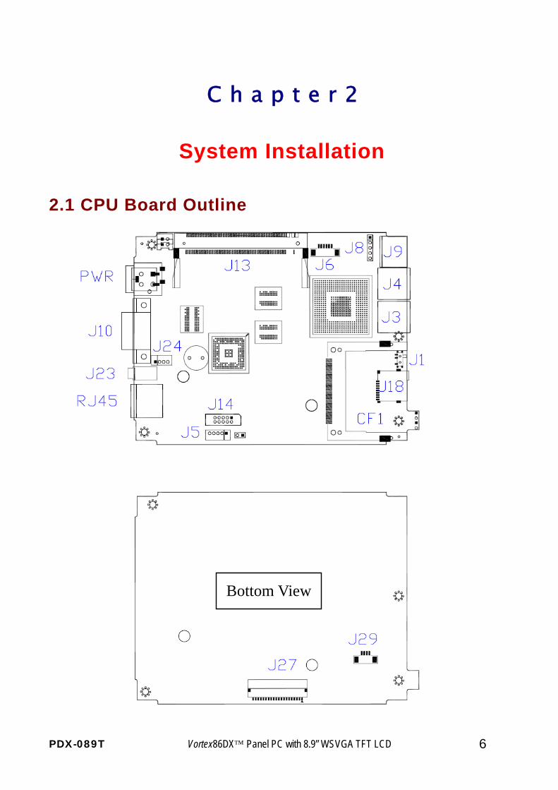
2.1 CPU Board Outline
Bottom View
PDX-089T Vortex86DX™ Panel PC with 8.9” WSVGA TFT LCD 7
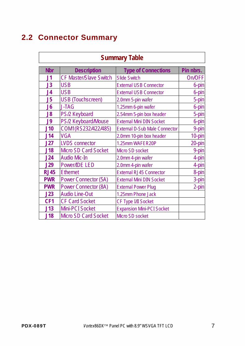
2.2 Connector Summary
Summary Table
Nbr Description Type of Connections Pin nbrs. J1 CF Master/Slave Switch Slide Switch On/OFF J3 USB External USB Connector 6-pin J4 USB External USB Connector 6-pin J5 USB (Touchscreen) 2.0mm 5-pin wafer 5-pin J6 J-TAG 1.25mm 6-pin wafer 6-pin J8 PS/2 Keyboard 2.54mm 5-pin box header 5-pin J9 PS/2 Keyboard/Mouse External Mini DIN Socket 6-pin
J10 COM1(RS232/422/485) External D-Sub Male Connector 9-pin J14 VGA 2.0mm 10-pin box header 10-pin J27 LVDS connector 1.25mm WAFER20P 20-pin J18 Micro SD Card Socket Micro SD socket 9-pin J24 Audio Mic-In 2.0mm 4-pin wafer 4-pin J29 Power/IDE LED 2.0mm 4-pin wafer 4-pin
RJ45 Ethernet External RJ45 Connector 8-pin PWR Power Connector (5A) External Mini DIN Socket 3-pin PWR Power Connector (8A) External Power Plug 2-pin J23 Audio Line-Out 1.25mm Phone Jack CF1 CF Card Socket CF Type I/II Socket J13 Mini-PCI Socket Expansion Mini-PCI Socket J18 Micro SD Card Socket Micro SD socket
PDX-089T Vortex86DX™ Panel PC with 8.9” WSVGA TFT LCD 8
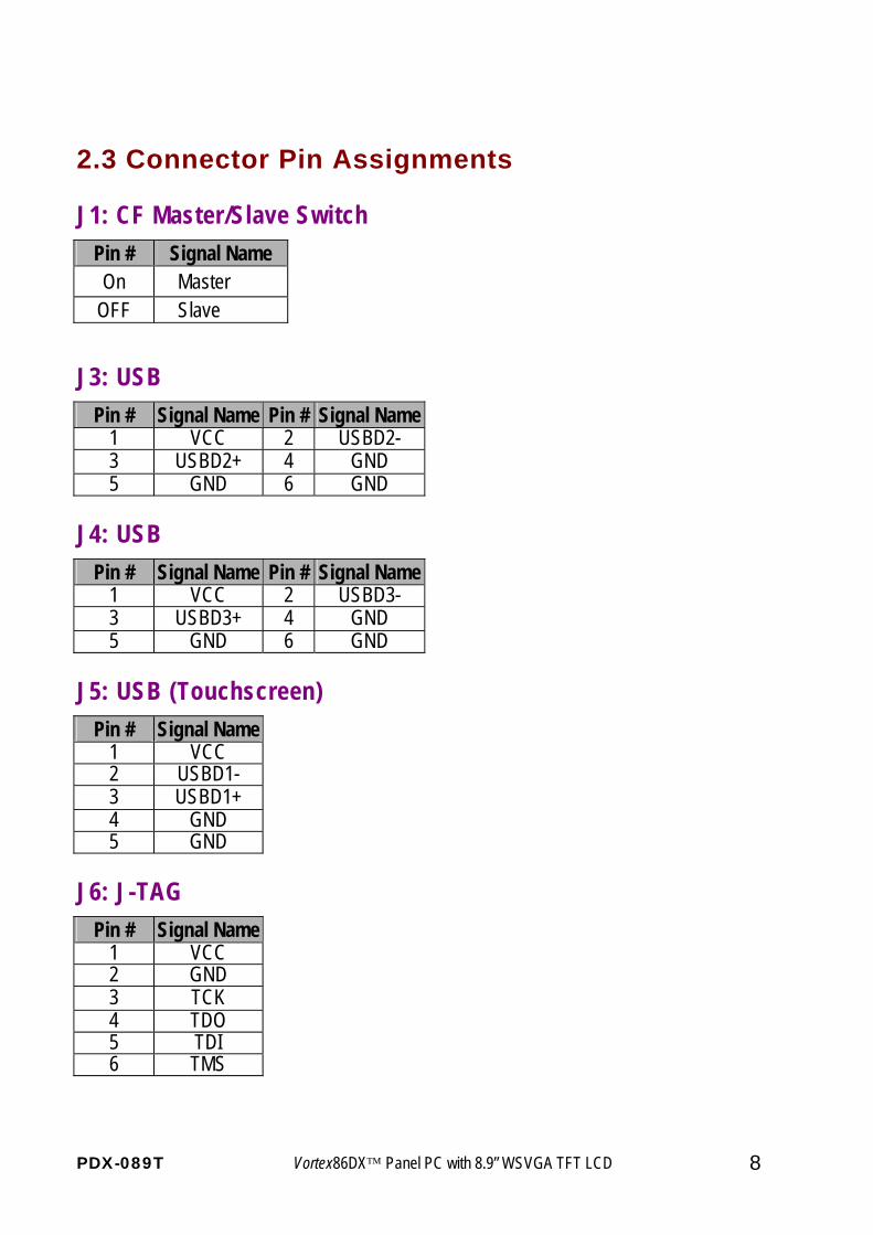
2.3 Connector Pin Assignments
J1: CF Master/Slave Switch
J3: USB Pin # Signal Name Pin # Signal Name
1 VCC 2 USBD2- 3 USBD2+ 4 GND 5 GND 6 GND
J4: USB Pin # Signal Name Pin # Signal Name
1 VCC 2 USBD3- 3 USBD3+ 4 GND 5 GND 6 GND
J5: USB (Touchscreen) Pin # Signal Name
1 VCC 2 USBD1- 3 USBD1+ 4 GND 5 GND
J6: J-TAG Pin # Signal Name
1 VCC 2 GND 3 TCK 4 TDO 5 TDI 6 TMS
Pin # Signal Name On Master
OFF Slave
PDX-089T Vortex86DX™ Panel PC with 8.9” WSVGA TFT LCD 9
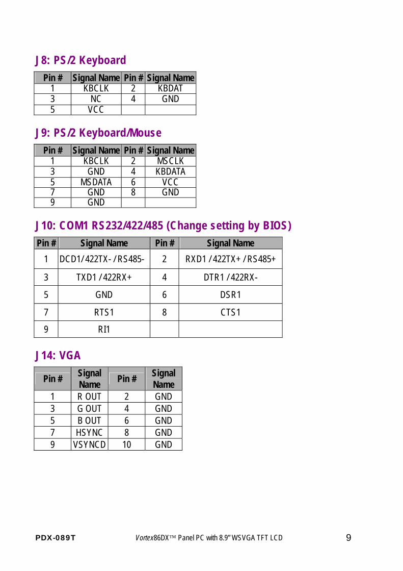
J8: PS/2 Keyboard Pin # Signal Name Pin # Signal Name
1 KBCLK 2 KBDAT 3 NC 4 GND 5 VCC
J9: PS/2 Keyboard/Mouse Pin # Signal Name Pin # Signal Name
1 KBCLK 2 MSCLK 3 GND 4 KBDATA 5 MSDATA 6 VCC 7 GND 8 GND 9 GND
J10: COM1 RS232/422/485 (Change setting by BIOS) Pin # Signal Name Pin # Signal Name
1 DCD1/ 422TX- / RS485- 2 RXD1 / 422TX+ / RS485+
3 TXD1 / 422RX+ 4 DTR1 / 422RX-
5 GND 6 DSR1
7 RTS1 8 CTS1
9 RI1
J14: VGA
Pin # Signal Name Pin # Signal
Name 1 R OUT 2 GND 3 G OUT 4 GND 5 B OUT 6 GND 7 HSYNC 8 GND 9 VSYNCD 10 GND
PDX-089T Vortex86DX™ Panel PC with 8.9” WSVGA TFT LCD 10
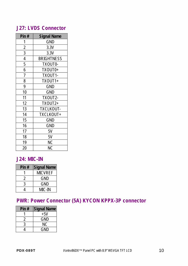
J27: LVDS Connector Pin # Signal Name
1 GND 2 3.3V 3 3.3V 4 BRIGHTNESS 5 TXOUT0- 6 TXOUT0+ 7 TXOUT1- 8 TXOUT1+ 9 GND
10 GND 11 TXOUT2- 12 TXOUT2+ 13 TXCLKOUT- 14 TXCLKOUT+ 15 GND 16 GND 17 5V 18 5V 19 NC 20 NC
J24: MIC-IN Pin # Signal Name
1 MICVREF 2 GND 3 GND 4 MIC-IN
PWR: Power Connector (5A) KYCON KPPX-3P connectorPin # Signal Name
1 +5V 2 GND 3 NC 4 GND
PDX-089T Vortex86DX™ Panel PC with 8.9” WSVGA TFT LCD 11
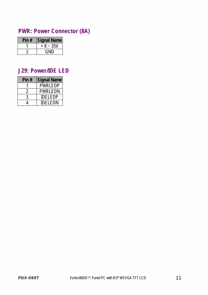
PWR: Power Connector (8A) Pin # Signal Name
1 + 8 ~ 35V 2 GND
J29: Power/IDE LED Pin # Signal Name
1 PWRLEDP 2 PWRLEDN 3 IDELEDP 4 IDELEDN
PDX-089T Vortex86DX™ Panel PC with 8.9” WSVGA TFT LCD 12
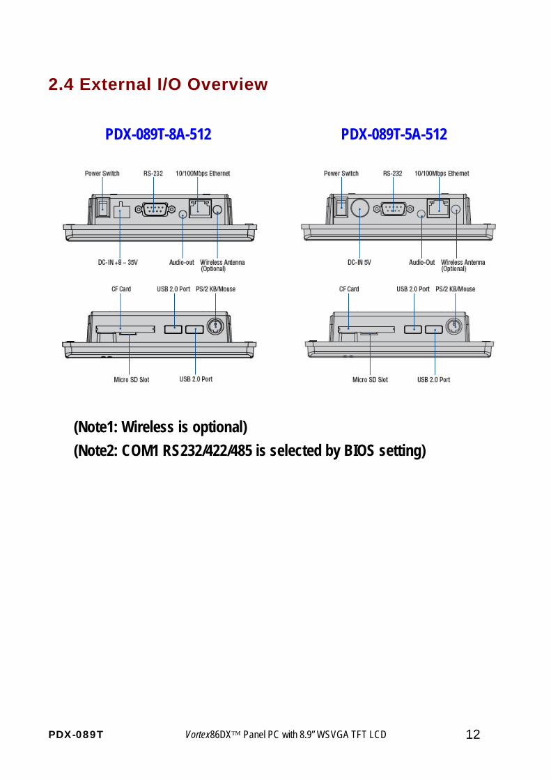
2.4 External I/O Overview
(Note1: Wireless is optional) (Note2: COM1 RS232/422/485 is selected by BIOS setting)
PDX-089T-5A-512 PDX-089T-8A-512
PDX-089T Vortex86DX™ Panel PC with 8.9” WSVGA TFT LCD 13
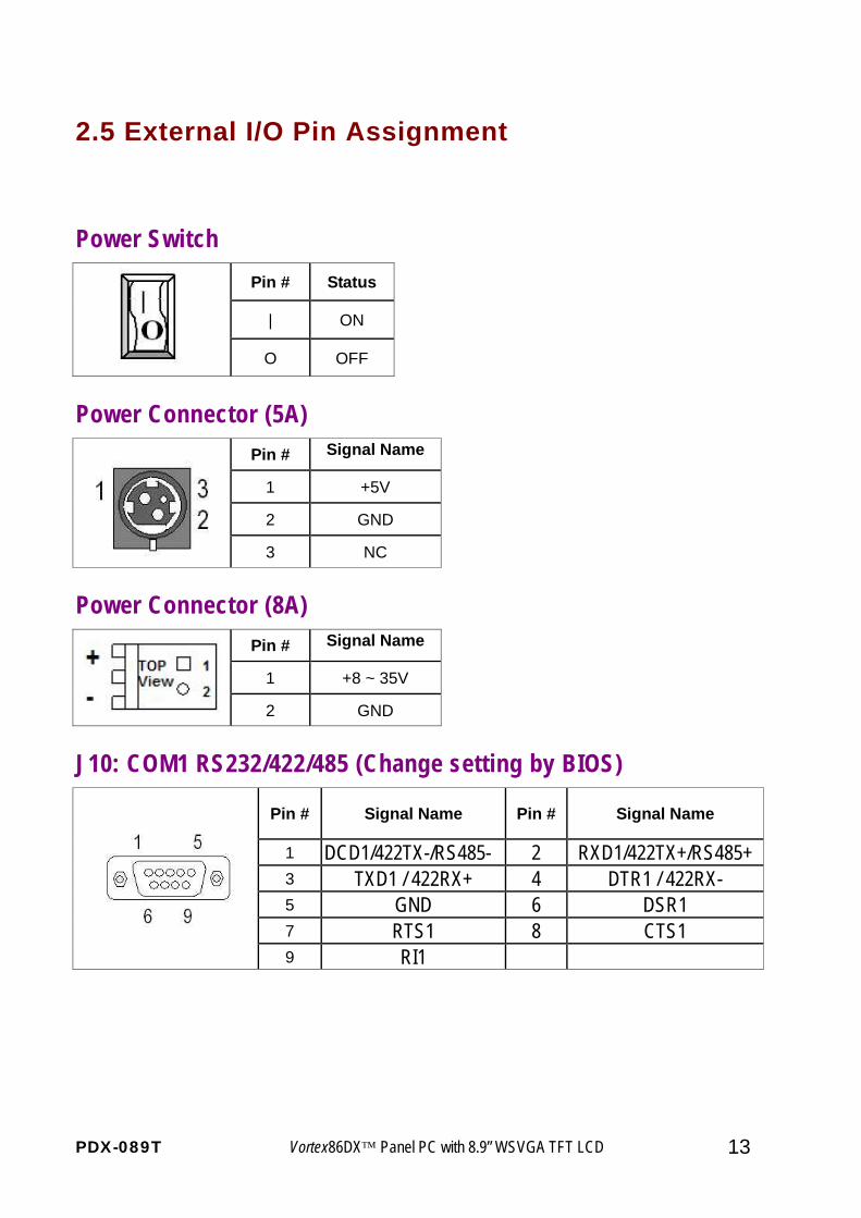
2.5 External I/O Pin Assignment
Power Switch Pin # Status
| ON
O OFF
Power Connector (5A) Pin # Signal Name
1 +5V
2 GND
3 NC
Power Connector (8A) Pin # Signal Name
1 +8 ~ 35V
2 GND
J10: COM1 RS232/422/485 (Change setting by BIOS)
Pin # Signal Name Pin # Signal Name
1 DCD1/422TX-/RS485- 2 RXD1/422TX+/RS485+ 3 TXD1 / 422RX+ 4 DTR1 / 422RX- 5 GND 6 DSR1 7 RTS1 8 CTS1
9 RI1
PDX-089T Vortex86DX™ Panel PC with 8.9” WSVGA TFT LCD 14
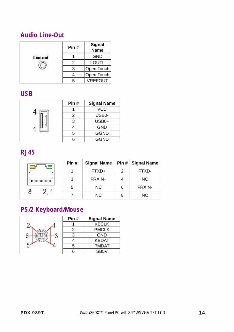
Audio Line-Out Pin # Signal
Name 1 GND 2 LOUTL 3 Open Touch4 Open Touch
5 VREFOUT
USB Pin # Signal Name
1 VCC 2 USB0- 3 USB0+ 4 GND 5 GGND
6 GGND
RJ45 Pin # Signal Name Pin # Signal Name
1 FTXD+ 2 FTXD-
3 FRXIN+ 4 NC
5 NC 6 FRXIN-
7 NC 8 NC
PS/2 Keyboard/Mouse Pin # Signal Name
1 KBCLK 2 PMCLK 3 GND 4 KBDAT 5 PMDAT 6 SB5V
PDX-089T Vortex86DX™ Panel PC with 8.9” WSVGA TFT LCD 15
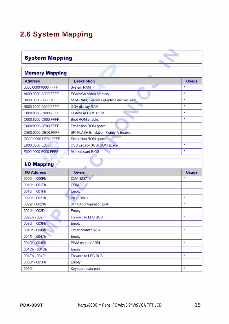
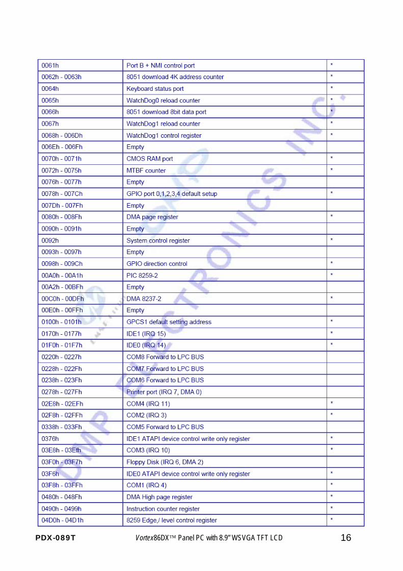
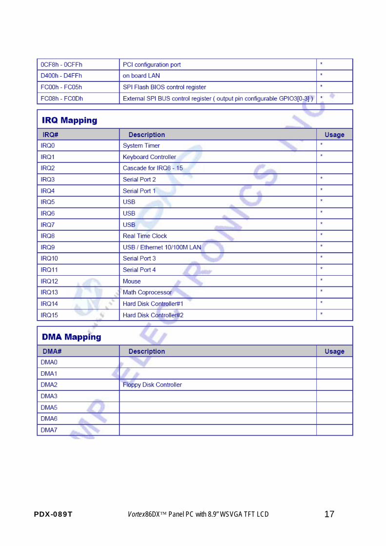
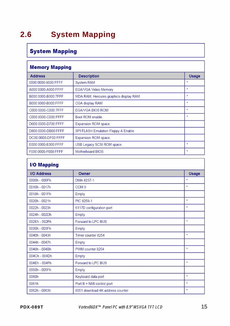
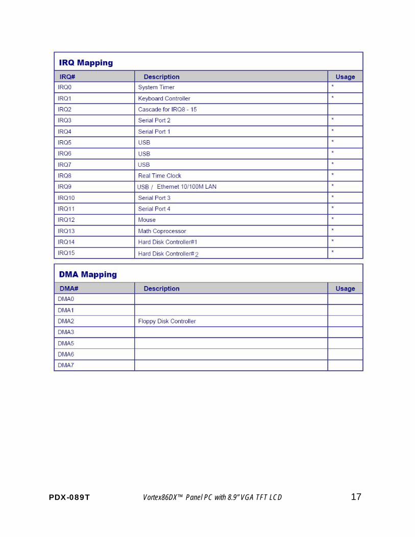
2.6 System Mapping
PDX-089T Vortex86DX™ Panel PC with 8.9” WSVGA TFT LCD 16
PDX-089T Vortex86DX™ Panel PC with 8.9” WSVGA TFT LCD 17
PDX-089T Vortex86DX™ Panel PC with 8.9” WSVGA TFT LCD 15
2.6 System Mapping
PDX-089T Vortex86DX™ Panel PC with 8.9” WSVGA TFT LCD 16
PDX-089T Vortex86DX™ Panel PC with 8.9” VGA TFT LCD 17
PDX-089T Vortex86DX™ Panel PC with 8.9” WSVGA TFT LCD 18
2.7 Watchdog Timer
There are two watchdog timers in PDX-089T, we can also provide DOS, Linux and WinCE example
for your reference.
PDX-089T Vortex86DX™ Panel PC with 8.9” WSVGA TFT LCD 19
C h a p t e r 3
Driver Installation VGA The Vortex86DX processor also use external Display chip ““Volari™ Z9s” which is an ultra low powered graphics chipset with total power consumption at around 1-1.5 W. LAN The Vortex86DX processor also integrated 10/100Mbps Ethernet controller that supports both 10/100BASE-T and allows direct connection to your 10/100Mbps Ethernet based Local Area Network for full interaction with local servers, wide area networks such as the Internet. I/O and IRQ settings can be done by software with the supplied utility software, or it can be set for Plug and Play compatibility. The controller supports: Half / Full-Duplex Ethernet function to double channel bandwidth, auto media detection. AUDIO CM119 is a highly integrated single chip USB audio controller specifically for VoIP (Voice over internet protocol) application. All essential analog modules are embedded in CM119, including dual DAC and earphone driver, ADC, microphone booster, PLL, regulator, and USB transceiver. 8 GPIO pins can constitute a 24 key matrix directly support keypad control function without MCU. Many features are programmable with jumper pins or external EEPROM. Vender can customize unique USB VID/PID to EEPROM for VoIP software authentication. Moreover, individual unique phone number for each device is possible via serial number stored in external EEPROM. Operating system support The PDX-089T provides the VGA and LAN drivers for DOS 6.22, Linux, CE 6.0, Windows XP Professional, and Windows Embedded standard (XPE).
PDX-089T Vortex86DX™ Panel PC with 8.9” WSVGA TFT LCD 20
3.1. PDX-089T Development Note
<Primary /Secondary IDE: Master or Slave>
Micro SD: Primary Master
CF Slot: Secondary IDE: Master or Slave (User can use slide switch (in side of CF slot) to adjust Master or Slave
<Linux installation note> Please forced the IDE setting in BIOS to PIO mode before install Linux on PDX-089T as follows: 1-Go to the advanced BIOS setting and make the “Onboard IDE Operate Mode” is “Legacy Mode” 2-Go to the PCI/PnP and make the “PCI IDE BusMaster” is “Disable"
< XP professional /Home /Embedded and Windows 2000 installation note >
1-Go to the Advanced and make "Onboard IDE operate Mode" "Native mode"
2-If your CF Card support UDMA2/4, please Go to the PCI PnP and make the “PCI IDE BusMaster” is “Enable”
<Enhance CF to run the UDMA2/4> 1-Make sure the CF Card is supporting UDMA 2/4 Mode or not. 2-Go to the PCI/PnP and make the “PCI IDE BusMaster” is “Enable”
<How to boot up from the Micro SD card>
1-Get into the BIOS setup Utility
2-Go to the Advanced 3-Choose Primary IDE Pin Select: SD card 4-Press “F10” to save configuration changes and exit setup
PDX-089T Vortex86DX™ Panel PC with 8.9” WSVGA TFT LCD 21
Note:
1-Wi-Fi module is optional. 2 -PDX-089T COM1: support RS232/422/485 and select by BIOS SETUP.
3 -PDX-089T series (CPU Speed: 1GHZ): Support Free DOS,DOS 6.22,DR-DOS,x-DOS,Xlinux,Embedded Linux, CE 6.0, Windows XP Professional, and Windows Embedded standard(XPE).
3.2. BIOS Default setting
If the system cannot be booted after BIOS changes are made, Please follow below procedures in
order to restore the CMOS as default setting.
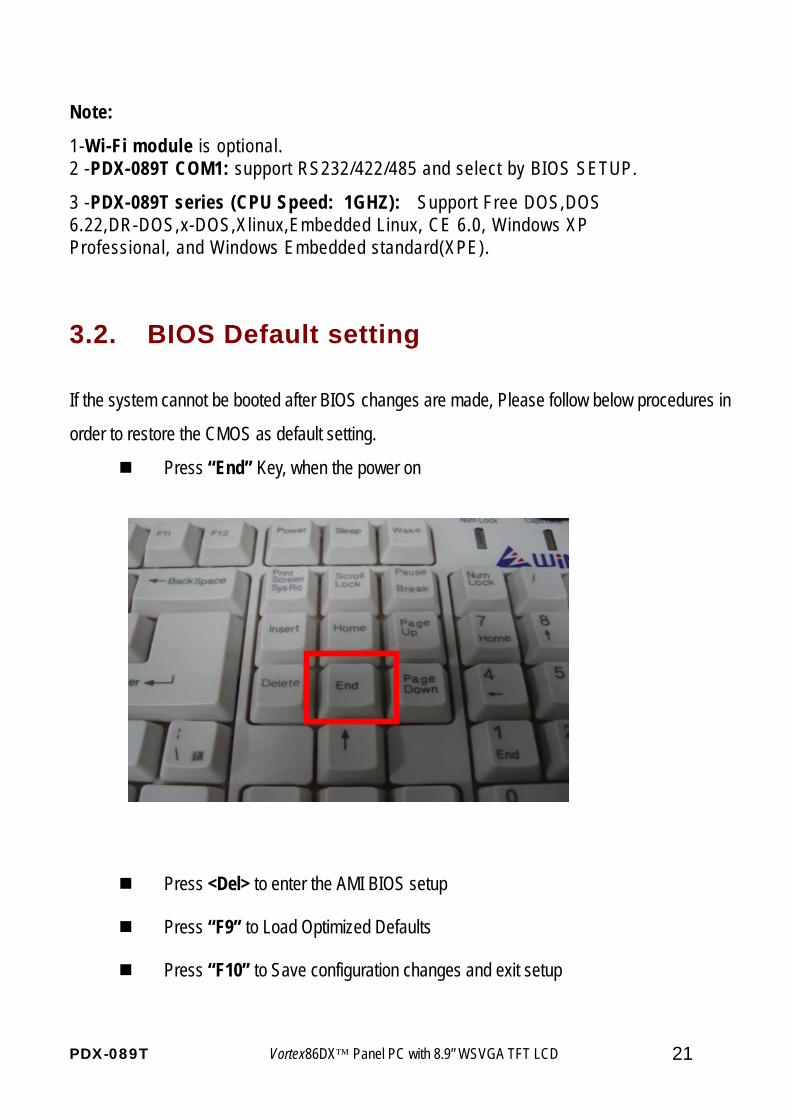
Press “End” Key, when the power on
Press <Del> to enter the AMI BIOS setup
Press “F9” to Load Optimized Defaults
Press “F10” to Save configuration changes and exit setup
PDX-089T Vortex86DX™ Panel PC with 8.9” WSVGA TFT LCD 22
Warranty This product is warranted to be in good working order for a period of one year from the date of purchase. Should this product fail to be in good working order at any time during this period, we will, at our option, replace or repair it at no additional charge except as set forth in the following terms. This warranty does not apply to products damaged by misuse, modifications, accident or disaster. Vendor assumes no liability for any damages, lost profits, lost savings or any other incidental or consequential damage resulting from the use, misuse of, originality to use this product. Vendor will not be liable for any claim made by any other related party. Return authorization must be obtained from the vendor before returned merchandise will be accepted. Authorization can be obtained by calling or faxing the vendor and requesting a Return Merchandise Authorization (RMA) number. Returned goods should always be accompanied by a clear problem description.
![Portland, OR - PBS · First Unitarian Church of Portland [PDX 02] Zion Lutheran Church [PDX 03] Trinity Episcopal Cathedral [PDX 04] Congregation Beth Israel [PDX 05] International](https://img.pdfslide.us/doc/110x75/604015f1647fd50f7b455674/portland-or-pbs-first-unitarian-church-of-portland-pdx-02-zion-lutheran-church.jpg)