Embed Size (px)
Citation preview

PDRP-1001/PDRP-1001A
D E L U G E ■■■■■ P R E A C T I O N C O N T R O L P A N E L
Doc.# 50734 ECN 97-514
ZONE 1
ZONE 2
WATERFLOW
SUPERVISORY
AC POWER
SYSTEM ALARM
RELEASE
SUPERVISORY
SYSTEMTROUBLE
TONESILENCE
ALARMSILENCE
ALARMACTIVATE RESET
CIRCUITTROUBLE
POWERTROUBLE
ALARMSILENCED
A Pittway Company

PDRP-1001/PDRP-1001A Document 50734 Rev B 12/21/97
2

PDRP-1001/PDRP-1001A Document 50734 Rev B 12/21/97
3
Table of ContentsI NFPA Standards ..............................................................4II Additional Information ...................................................4
1.0 The PDRP-1001/PDRP-1001A ....................................................... 51.1 Features ........................................................................................................ 51.2 Circuits .......................................................................................................... 51.3 Optional Boards ............................................................................................ 71.4 Remote Annunciator ..................................................................................... 81.5 Optional Meters ............................................................................................. 81.6 Specifications................................................................................................ 9
2.0 System Operation .........................................................................112.1 System Status LEDs ................................................................................... 112.2 Control Switches ......................................................................................... 122.3 Zone Status LEDs ....................................................................................... 122.4 Supervisory ................................................................................................. 132.5 Zone Disable .............................................................................................. 132.6 Last Event Recall ........................................................................................ 13
3.0 Installation Procedure ..................................................................143.1 General ....................................................................................................... 143.2 Initiating Device Circuits ............................................................................. 153.3 4-Wire Smoke Detector Connections .......................................................... 163.4 Output Circuits ............................................................................................ 173.5 Power .......................................................................................................... 183.6 Optional Modules ........................................................................................ 203.7 Dip Switch Location and Descriptions ........................................................ 253.8 Setting Mode of Operation .......................................................................... 26
Appendix A: Power Calculations ......................................................27Appendix B: Device Compatibility Chart .........................................29Appendix C: NFPA Standard Specific Requirements ....................33Troubleshooting Table ........................................................................38

PDRP-1001/PDRP-1001A Document 50734 Rev B 12/21/97
4
I NFPA StandardsThis control panel complies with the following NFPA standards:NFPA 13 Sprinkler SystemsNFPA 15 Water Spray SystemsNFPA 16 Foam-Water Deluge and Foam-Water Spray SystemsNFPA 72 Central Station Signaling Systems (Automatic, Manual, and Waterflow). ProtectedPremises Unit (Requires NOTI-FIRE 911AC DACT or MS5012 Slave Communicator).*NFPA 72 Local (Automatic, Manual, Waterflow and Sprinkler Supervisory) Fire Alarm Systems.NFPA 72 Auxiliary (Automatic, Manual, and Waterflow) Fire Alarm Systems. (Requires 4XTM.)NFPA 72 Remote Station (Automatic, Manual, and Waterflow) Fire Alarm Systems. (Requires4XTM or NOTI•FIRE 911AC DACT.) *
* Applications which require the NOTI-FIRE 911AC is not FM approved.
II Additional Information Note: Before proceeding, the installer should be familiar with the following documents and standards:
NFPA Standards:NFPA 13 Installation of Sprinkler SystemsNFPA 15 Water Spray Fixed SystemsNFPA 16 Deluge Foam-Water Sprinkler and Foam-Water Spray SystemsNFPA 72 Installation, Maintenance, and Use of Central Station Signaling SystemsNFPA 72 Local, Auxiliary, Remote Station and Proprietary Fire Alarm SystemsNFPA 72 Automatic Fire DetectorsNFPA 72 Installation, Maintenance, and Use of Notification Appliances for Fire Alarm SystemsNFPA 72 Testing Procedures for Signaling Systems
Underwriters Laboratories Documents:UL 38 Manually Actuated Signaling BoxesUL 217 Smoke Detectors, Single and Multiple StationUL 228 Door Closers - Holders for Fire Alarm SystemsUL 268 Smoke Detectors for Fire Alarm SystemsUL 268A Smoke Detectors for Duct ApplicationsUL 346 Waterflow Indicators for Fire Alarm SystemsUL 464 Audible Signaling AppliancesUL 521 Heat Detectors for Fire Alarm SystemsUL 864 Standard for Control Units for Fire Alarm SystemsUL 1481 Power Supplies for Fire Alarm SystemsUL 1638 Visual Signaling AppliancesUL 1971 Signaling Devices for the Hearing ImpairedCAN/ULC-S524-M91 Standard for Installation of Fire Alarm SystemsCAN/ULC-S527-M87 Standard for Control Units for Fire Alarm Systems
Other:NEC Article 300 Wiring MethodsNEC Article 760 Fire Alarm SystemsApplicable Local and State Building CodesRequirements of the Local Authority Having JurisdictionNotifier Device Compatibility Document, 15378.ADA Americans with Disabilities Act
PDRP-1001/PDRP-1001A Document 50734 Rev B 12/21/97
5
1.0 The PDRP-1001/PDRP-1001A
1.1 Features
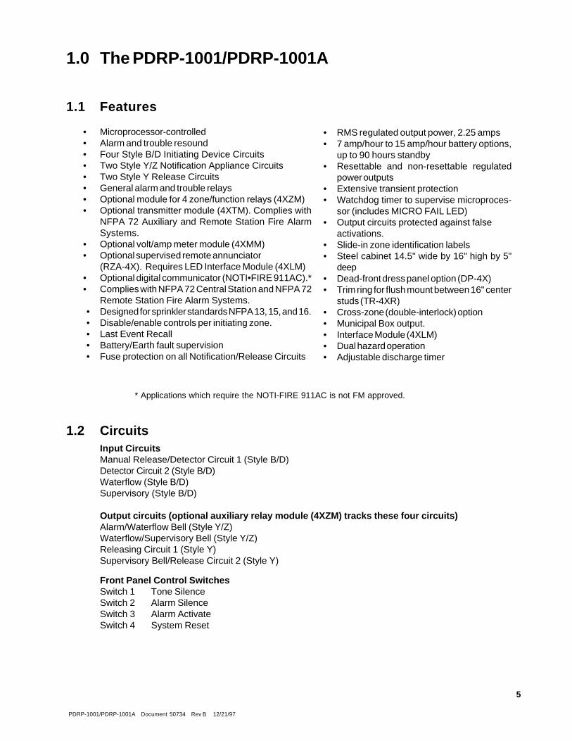
• Microprocessor-controlled• Alarm and trouble resound• Four Style B/D Initiating Device Circuits• Two Style Y/Z Notification Appliance Circuits• Two Style Y Release Circuits• General alarm and trouble relays• Optional module for 4 zone/function relays (4XZM)• Optional transmitter module (4XTM). Complies with
NFPA 72 Auxiliary and Remote Station Fire AlarmSystems.
• Optional volt/amp meter module (4XMM)• Optional supervised remote annunciator
(RZA-4X). Requires LED Interface Module (4XLM)• Optional digital communicator (NOTI•FIRE 911AC).*• Complies with NFPA 72 Central Station and NFPA 72
Remote Station Fire Alarm Systems.• Designed for sprinkler standards NFPA 13, 15, and 16.• Disable/enable controls per initiating zone.• Last Event Recall• Battery/Earth fault supervision• Fuse protection on all Notification/Release Circuits
• RMS regulated output power, 2.25 amps• 7 amp/hour to 15 amp/hour battery options,
up to 90 hours standby• Resettable and non-resettable regulated
power outputs• Extensive transient protection• Watchdog timer to supervise microproces-
sor (includes MICRO FAIL LED)• Output circuits protected against false
activations.• Slide-in zone identification labels• Steel cabinet 14.5" wide by 16" high by 5"
deep• Dead-front dress panel option (DP-4X)• Trim ring for flush mount between 16" center
studs (TR-4XR)• Cross-zone (double-interlock) option• Municipal Box output.• Interface Module (4XLM)• Dual hazard operation• Adjustable discharge timer
* Applications which require the NOTI-FIRE 911AC is not FM approved.
1.2 CircuitsInput CircuitsManual Release/Detector Circuit 1 (Style B/D)Detector Circuit 2 (Style B/D)Waterflow (Style B/D)Supervisory (Style B/D)
Output circuits (optional auxiliary relay module (4XZM) tracks these four circuits)Alarm/Waterflow Bell (Style Y/Z)Waterflow/Supervisory Bell (Style Y/Z)Releasing Circuit 1 (Style Y)Supervisory Bell/Release Circuit 2 (Style Y)
Front Panel Control SwitchesSwitch 1 Tone SilenceSwitch 2 Alarm SilenceSwitch 3 Alarm ActivateSwitch 4 System Reset

PDRP-1001/PDRP-1001A Document 50734 Rev B 12/21/97
6
Figure 1.0-1: PDRP-1001/PDRP-1001A Installation Diagram

PDRP-1001/PDRP-1001A Document 50734 Rev B 12/21/97
7
1.3 Optional Boards
The PDRP-1001/PDRP-1001A has mounting slots for two option boards. Any two of the three optionmodules may be installed.
Transmitter Module (4XTM NOTIFIER)The Transmitter Module provides a supervised output for local energymunicipal box transmitter (for NFPA 72-1993 Auxiliary Fire Alarm System)and alarm and trouble reverse polarity circuits (for NFPA 72-1993 RemoteStation Fire Alarm System). Also included is a DISABLE switch and disabletrouble LED.
As a jumper option, the alarm reverse polarity circuit will open on trouble if no alarmexists.
LED Interface Module (4XLM NOTIFIER)The LED Interface Module supports the RZA-4X Remote Annunciatormodule. Annunciator wiring is supervised for open conditions by this module.The Annunciator Driver Module mounts to the main board, occupying one ofthe two option connectors.
Zone Relay Module (4XZM NOTIFIER)The Zone Relay module provides Form-C contacts for the following:
• Alarm/Waterflow Bell• Waterflow/Supervisory Bell• Releasing Circuit 1• Supervisory Bell/Release Circuit 2• System Alarm• System Trouble
As a jumper option, the first four relays described above can be made silenceable.
PDRP-1001/PDRP-1001A Document 50734 Rev B 12/21/97
8
LED Interface Module (4XLM NOTIFIER)Maximum voltage/current, each output: 27.6V/8mA.
Note: Outputs are power limited.
Zone Relay Module (4XZM NOTIFIER)Dry Form-C contacts rated: 2.0 amps @ 30 VDC (resistive), 0.5 amps @ 30 VAC (resistive).
1.4 Remote Annunciator
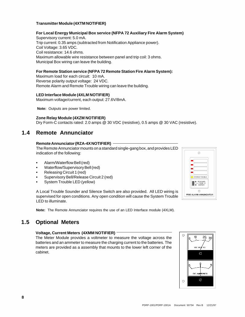
Remote Annunciator (RZA-4X NOTIFIER)The Remote Annunciator mounts on a standard single-gang box, and provides LEDindication of the following:
• Alarm/Waterflow Bell (red)• Waterflow/Supervisory Bell (red)• Releasing Circuit 1 (red)• Supervisory Bell/Release Circuit 2 (red)• System Trouble LED (yellow)
A Local Trouble Sounder and Silence Switch are also provided. All LED wiring issupervised for open conditions. Any open condition will cause the System TroubleLED to illuminate.
Note: The Remote Annunciator requires the use of an LED Interface module (4XLM).
1.5 Optional Meters
Voltage, Current Meters (4XMM NOTIFIER)The Meter Module provides a voltmeter to measure the voltage across thebatteries and an ammeter to measure the charging current to the batteries. Themeters are provided as a assembly that mounts to the lower left corner of thecabinet.
Transmitter Module (4XTM NOTIFIER)
For Local Energy Municipal Box service (NFPA 72 Auxiliary Fire Alarm System)Supervisory current: 5.0 mA.Trip current: 0.35 amps (subtracted from Notification Appliance power).Coil Voltage: 3.65 VDC.Coil resistance: 14.6 ohms.Maximum allowable wire resistance between panel and trip coil: 3 ohms.Municipal Box wiring can leave the building.
For Remote Station service (NFPA 72 Remote Station Fire Alarm System):Maximum load for each circuit: 10 mA.Reverse polarity output voltage: 24 VDC.Remote Alarm and Remote Trouble wiring can leave the building.

PDRP-1001/PDRP-1001A Document 50734 Rev B 12/21/97
9
AC CircuitBreaker
1.6 Specifications
AC PowerFor PDRP-1001/PDRP-1001A: 120 VAC, 50/60 Hz, 1.2 ampsWire size: minimum #14 AWG with 600V insulation
Battery (lead acid only)Maximum Charging Circuit: 27.6V, 1.5 ampsMaximum Battery Capacity: 15 AH. (Batteries larger than 12 AH require Notifier#BB-17 or other UL listed battery cabinet.)
Initiating Device CircuitsPower-limited circuitryOperation: Style B (Class B)/ Style D (Class A)Normal Operating Voltage: 24 VDC (ripple = 1.0V peak-to-peak)Alarm current: 15 mA minimumShort circuit current: 40 mA maximumMaximum detector current in standby: 2 mA (max) per zoneMaximum loop resistance: 200 ohmsEnd-of-line resistor: 4.7K, 1/2-Watt (NOTIFIER part # 71252 UL listed)Detector loop current is sufficient to ensure operation of one alarmed detector per zone.Supervisory current: 5 mA (including end-of-line resistor)
Notification Appliance and Releasing CircuitsPower-limited circuitryMaximum allowable voltage drop due to wiring: 2 VDCNormal Operating Voltage: 24 VDCTotal current available to all external devices: 2.25 amps.Maximum signaling current per circuit: 1.5 ampsEnd-of-line resistor: 4.7K, 1/2-Watt (NOTIFIER part # 71252 UL listed)
Alarm and Trouble RelaysDry Form-C contacts rated: 2.0 amps @ 30 VDC (resistive), 0.5 amps @ 30 VAC (resistive).All relays must be connected to a power-limited power supply.
Four-wire Smoke Detector PowerUp to 200 mA is available for powering 4-wire smoke detectors.Maximum ripple voltage: 1.0 V p/p
Non-resettable PowerTotal DC current available from this output is up to 200 mA (subtracted from four-wire smoke power).Maximum ripple voltage: 1.0 V p/p
RMS Regulated PowerTotal DC current available for powering external devices is 0.5 amp (subtracted from 2.25amps available to notification appliance circuits).Maximum ripple voltage: 100 mV p/p
Note : For device compatibility data, refer to the Device Compatibility Chart, Appendix B.
P1 P2 P3 P4
Output Circuit PTCs

PDRP-1001/PDRP-1001A Document 50734 Rev B 12/21/97
10
Cabinet = 5.375"Backbox = 4.750"
Door = 16.125"Backbox = 16"
Door = 14.625"Backbox = 14.5"
Figure 1.6-1: Cabinet Dimensions
Optional Trim RingTR-4XR

PDRP-1001/PDRP-1001A Document 50734 Rev B 12/21/97
11
2.0 System Operation
2.1 System Status LEDs
Alarm, Trouble and Supervisory LEDs will flash on and off until the event(s) has been acknowledged (TONEor ALARM SILENCE), at which point the LED will illuminate steadily.
AC POWERGreen LED that illuminates steadily to indicatepresence of AC power.
SYSTEM ALARMRed LED that flashes when an alarm occurs.
RELEASERed LED that illuminates steadily when releaseoccurs. After theDischarge Timer has expired, the LED will flash.
SUPERVISORYYellow LED that flashes upon activation of asupervisory device (such as tamper switch) onZone 4.
SYSTEM TROUBLEYellow LED that flashes for any trouble condition,including those associated with option boards.
CIRCUIT TROUBLEYellow LED that flashes for trouble conditions onoutput circuits (notification and releasing circuits).
ALARM SILENCEDYellow LED that illuminates steadily when theALARM SILENCE switch has been pushed afteran alarm.
POWER TROUBLEYellow LED that flashes for low or disconnectedbatteries and earth fault conditions.
BATTYellow LED that illuminates steadily onmotherboard when battery is low or not detected(not visible through door).
EARTHYellow LED that illuminates steadily onmotherboard during a ground fault condition (notvisible through door).
MICRO FAILYellow LED that illuminates on motherboard whenwatchdog timer detects microprocessor failure(not visible through door).

PDRP-1001/PDRP-1001A Document 50734 Rev B 12/21/97
12
2.2 Control Switches
Tone SilenceAcknowledge alarms, troubles and supervisories. The panel has alarmand trouble resound with LED flash of new conditions. The flashingtrouble LED(s) illuminate steadily on TONE SILENCE and the piezosounder silences. A second trouble will resound the piezo. The piezo hasthree distinct sounds for alarm, trouble, and supervisory. Trouble condi-tions are self restoring. Alarms and supervisories latch and requireRESET to clear.
Alarm SilenceAcknowledge for alarms and supervisories. The ALARM SILENCEswitch will silence the local piezo, change any flashing alarm LEDs tosteady, and turn off the notification appliance circuits (not the ReleasingCircuits) . The “ALARM SILENCED” LED will illuminate. Alarm silenceis a latching function and requires a RESET to clear.
Note: Releasing Circuits will turn off only if Discharge timer criteria is satisfiedsee "Setting Mode of Operation".
Alarm ActivateThe ALARM ACTIVATE switch may be used to activate NotificationAppliance Circuits. ALARM ACTIVATE also activates the SystemAlarm relay. ALARM ACTIVATE is a latching function. Pressing ALARMSILENCE silences the notification appliance circuits and System AlarmRelay and lights the Alarm Silenced LED. Pressing RESET returns thesystem to normal.
System ResetThe RESET switch breaks power to all initiating device circuits, 4-wiresmoke power and option boards and will clear any activated outputcircuits. If any alarm or trouble still exists after reset, they will reactivatethe panel. Holding RESET down will perform a LAMP TEST function andwill activate the piezo sounder.
2.3 Zone Status LEDs
The alarm and/or trouble LED(s) will flash until theevent(s) has been acknowledged (TONE orALARM SILENCE), at which point the LED(s) willilluminate steadily. ZONE 1
ZONE 2
WATERFLOW
SUPERVISORY
ALARM LED
TROUBLE LED
ALARM LED
TROUBLE LED
ALARM LED
TROUBLE LED
(NOT USED)
TROUBLE LED

PDRP-1001/PDRP-1001A Document 50734 Rev B 12/21/97
13
2.4 Supervisory
Zone 4 is always used for monitoring supervisory devices (such as valve tamper switches). A short circuiton this zone (activation of a N.O. contact) will cause the supervisory LED and the zone 4 yellow LED to flash.The piezo sounder will generate a unique Pressing TONE SILENCE will silence the piezo and cause thesupervisory LED to illuminate steadily, but the Zone 4 Trouble LED will continue to flash. Supervisorysignals latch and require RESET to clear. The ALARM SILENCE switch will silence the piezo, cause thesupervisory LED to illuminate steadily and turn off the Supervisory Notification Appliance Circuit. An opencircuit on Zone 4 will be reported as a zone trouble.
2.5 Zone Disable
If a zone has been disabled, an alarm that occurs on that zone will flashthe red zone LED, but neither the piezo nor any output circuit will activate.If both power sources are removed from the system, all zones will be re-enabled upon restoration of power. Disable status will be lost.
The Zone Disable routine makes use of the four panel switches as follows:
1) Press and hold in the TONE SILENCE switch.
2) With the TONE SILENCE switch held in, press (in sequence) the ALARMSILENCE switch, the ALARM ACTIVATE switch, and then the RESETswitch.
3) The Zone 1 Alarm LED will flash.
4) To disable Zone 1, press the RESET switch. The Zone 1 yellow LED will light to show that the zone is disabled.
Note: The RESET switch toggles disable status for the selected zone.
5) To select the next zone, press the ALARM SILENCE switch.
6) To select the previous zone, press the ALARM ACTIVATE switch.
7) When disable selections are complete, release the TONE SILENCE switch.
If any zone has been disabled, the trouble relay will activate and System Trouble LED will flash.
2.6 Last Event Recall
Last Event Recall allows the user to display the previous panel status. The Last Event Recall makes useof the four panel switches as follows:
1) Press and hold in the TONE SILENCE switch.
2) With the TONE SILENCE switch held in, press (in sequence) the RESETswitch, the ALARM ACTIVATE switch, and then the ALARM SILENCE switch.
3) Last Event is displayed.
4) Release the TONE SILENCE switch to return to normal operation.
Note: To clear the Last Event buffer, press RESET twice.

PDRP-1001/PDRP-1001A Document 50734 Rev B 12/21/97
14
3.1 General
Carefully unpack the system and check for shipping damage. Mount the cabinet in a clean, dry, vibration-free area in which extreme temperatures are not encountered. The location should be readily accessiblewith sufficient room for easy installation and maintenance. Locate the top of the cabinet approximately fivefeet above the floor with the hinge mounting on the left. Determine the number of conductors required forthe devices to be employed. Pull required conductors into the box through the knockout provided. All wiringshould be in accordance with the National and/or Local codes for fire alarm systems.
UL Power Limited Wiring RequirementsPower limited and non-power limited circuit wiring must remain separated in the cabinet. All power limitedcircuit wiring must remain at least 0.25" away from any non-power limited circuit wiring. Furthermore, allpower limited circuit wiring and non-power limited circuit wiring must enter and exit the cabinet throughdifferent knockouts and/or conduits. A typical wiring diagram for the PDRP-1001/PDRP-1001A is shownbelow.
3.0 Installation Procedure
Figure 3.1-1: Typical Wiring Diagram for UL Power-Limited Requirements
PC Board
AC Power PowerLimitedCircuit
Non-PowerLimitedCircuit
Initiating CircuitsBell Circuits
Relays
Power LimitedCircuits
Non-PowerLimited Circuits
Power LimitedCircuits

PDRP-1001/PDRP-1001A Document 50734 Rev B 12/21/97
15
3.2 Initiating Device Circuits
ZonesWire all alarm initiating devices sequentially for proper supervision. Initiating devices include: heat,photoelectric, and ionization type detectors; and waterflow alarm devices. Refer to the Device CompatibilityChart, Appendix B.
Notes:1) Observe polarity when connecting polarized devices.2) All circuits are supervised and power limited.3) Leave Dummy Load (provided) on all unused circuits.
Figure 3-2: Ffffff
Figure 3.2-1: Example of Initiating Device Circuits
IN #1 IN #2 IN #3 IN #41 2 3 4 5 6 7 8 9 10 11 12 13 14 15 16
B+ A+ A- B- B+ A+ A- B- B+ A+ A- B- B+ A+ A- B-TB4
Style BInitiating Device
Circuit
Style DInitiating Device
Circuit
HeatDetector
Two-wireSmoke Detector
ManualRelease
Normally OpenWaterflowDevices orPressureSwitches
Normally OpenTamper Switches
or PressureSwitches
+ -
+ -
+-
+
-
+ -
+ -
Style BSupervisory
Circuit
4.7K, 1/2-Watt(NOTIFIER part # 71252,
UL listed)
4.7K, 1/2-Watt(NOTIFIER part # 71252,
UL listed)

PDRP-1001/PDRP-1001A Document 50734 Rev B 12/21/97
16
Notes on Style B and Style D field wiring:1) The Power Supervision Relay coil leads must be connected to the last detector base 24V screw terminals.2) Calculation of the maximum allowable resistance in the 24VDC detector power wiring:
Where:
RMAX
is the maximum resistance of the 24V wires.
VOM
is the minimum operating voltage of the detector or end-of-line relay, whichever is
greater, in volts.
N is the total number of detectors on the 24V supply loop.
IS is the detector current in standby.
NA is the number of detectors on the 24V power loop which must function at the same
time in alarm.
IS is the detector current in alarm.
IR is the end-of-line relay current.
3.3 4-Wire Smoke Detector Connections
24 VDC (+)
Common (-)
IDC(+)
IDC(-)
Red
Black
24 VDC (+)
Common (-)
IDC(+)
IDC(-)
UL-listed 24 VDCFour-Wire Smoke Detectors
UL Listed4.7K, 1/2-Watt
ELR
TB1
1 2 3 4
+ -TB4
1 2 3 4
B+ A+ A- B-
+24VR
A maximum of 200mA is available from the+24VDC 4-wire smoke detector power cir-cuit on TB1 terminals 3 and 4. Any power thatis drawn from the +24VDC Non-ResettablePower on TB2 terminals 1 and 2 must besubtracted from available 4-wire detectorpower. See Sections "Specifications" and"Power".
IN #1Style B Initiating Device Circuit
Initiating Device Circuits 1, 2, 3, or 4can be used. Style D wiring can also beemployed.
ListedPower
SupervisionRelay
Refer to the Device Compatibility Chart (Appendix B), for suitable 4-wire smoke detectors.
Figure 3.3-1: Diagram of connections for a 4-Wire Smoke Detector
RMAX
= (20.6 - VOM
)
(N x IS) + (N
A x I
A) + (I
R)

PDRP-1001/PDRP-1001A Document 50734 Rev B 12/21/97
17
3.4 Output CircuitsNotification Appliance CircuitsThis control panel can provide two Style Y/Z Notification Appliance Circuits and two Style Y ReleasingCircuits (see Section "Dip Switch Location and Descriptions" for DIP switch configuration). Each circuitis capable of 1.5 amps of current. Total current drawn from all four circuits cannot exceed 2.25 amps. Referto the Device Compatibility Chart, Appendix B. Circuits are supervised and power-limited.
Note: Wiring must be configured to maintain a minimum voltage of 20.4V on release circuits. Calculation of maximum allowable resistance:
RMAX
= 20.6V - 20.4V
IS
Where: RMAX
= maximum allowable resistance of wiring IS = solenoid current
3 4 5 6 7 8 9 10 11 12 13 14 15 16
Polarized Bell
Polarized Strobe
Polarized Horn
B+ A+ A- B- B+ A+ A- B- NC B+ B- NC B+ B-
Style ZNotification
Appliance Circuit
Style YNotification
Appliance Circuit
B+ A+ A- B- B+ A+ A- B- B+ B- B+
4.7K, 1/4-WattUL-listed End-of-Line device
Dummy Load all unusedNotification Appliance Circuits
Dummy Load all unusedReleasing Circuits
4.7K, 1/2-Watt(part # 71252, UL listed)
4.7K, 1/4-WattUL-listed End-of-Line device
TB2
UL listed & FM approvedSolenoid Release Valves(see Device Compatibility
Document)
Releasing Circuits
No
Con
nect
ion
No
Con
nect
ion
Figure 3.4-1: Notification Appliance Circuits
OUT #1 OUT #2 OUT #3 OUT #4

PDRP-1001/PDRP-1001A Document 50734 Rev B 12/21/97
18
3.5 Power
CAUTION: Several different sources of power can be connected to this panel. Disconnectall sources of power before servicing. The panel and associated equipment may bedamaged by removing and/or inserting cards, modules, or interconnecting cables whilethis unit is energized.
This output is not suitable forpowering devices requiring fil-tered, regulated DC power.
The combined current draws from the Resettable and Non-Resettableoutputs cannot exceed 200 mA.
Alarm RelayOne Form-C dry alarm contact is provided in the basic panel for controlling supplementary devices. It israted 2 amps at 30 VDC and 0.5 amps at 30 VAC (resistive) and is non-silenceable when an alarm occurs.See below for terminal location.
Trouble RelayOne Form-C dry trouble contact is provided in the basic panel for controlling supplementary devices. Itis rated 2 amps at 30 VDC and 0.5 amps at 30 VAC (resistive) and will silence when trouble condition iscleared. See below for terminal location.
Note: The alarm and trouble Form-C dry contact relays must be power limited relays. Theymust be wired from one of the 24V power limited terminals as shown in the figure belowor a comparable UL listed power limited power supply.
ALARM TROUBLENO NC C NO NC C
Alarm Trouble
Figure 3.4-2: Alarm/Trouble Coils and Contacts.
+24VU +24VR +24VNR + - + - + -
- -
-
- -
-
- -
-or or
1 2 3 4 5 61 2 3 4 1 2
TB1TB2
TB3
RMS-Regulated Power24 VDC power for inductive-typedevices such as door holders canbe connected to TB1 terminals 1(+)and 2 (-).
+24VU +24VR +24VNR + - + - + -
4-Wire Smoke Detector Power24 VDC filtered, regulated, resettablepower for 4-wire smoke detectors canbe obtained from TB1 Terminals 3 (+)and 4 (-).
Non-resettable Power24 VDC filtered, regulated, non-reset-table power can be drawn from TB2Terminals 1 (+) and 2 (-).
1 2 3 4
Figure 3.5-1: Diagram of Power Terminals
TB11 2
TB2

PDRP-1001/PDRP-1001A Document 50734 Rev B 12/21/97
19
Voltmeter/AmmeterTo monitor battery voltage and battery charging current, a 4XMM (NOTIFIER) is required. To install thepower meter module, remove the jumper labeled "AMP" and connect cable assembly P2 to pin connectorJ2 and cable assembly P3 to pin connector J3 on the main board. Secure the 4XMM to the backbox withthe two screws provided. On some models, it will be necessary to install the meter bracket with the nutsand bolts provided.
J2
J3
AC PowerPrimary power required for the PDRP-1001/PDRP-1001A panel is 120 VAC, 50/60 Hz, 1.2 amps.Overcurrent protection for this circuit must comply with Article 760 of the National Electrical Code (NEC)and/or local codes. Use #14 AWG or larger wire with 600 volt rating.
Battery PowerObserve polarity when connecting battery. Connect battery cable to J9 on the main board using the plug-in connector provided. See Appendix A for calculation of correct battery rating.
CAUTION: Batteries contain sulfuric acid which can cause severe burns to the skin andeyes, and can destroy fabrics. If contact is made with sulfuric acid, immediately flush skinor eyes with water for 15 minutes and seek immediate medical attention.
Figure 3.5-2: Diagram of the 4XMM Voltmeter Connected to the Main Board
J9

PDRP-1001/PDRP-1001A Document 50734 Rev B 12/21/97
20
3.6 Optional Modules
The fire control panel has two module connectors - J5 and J8. Three modules are available for the paneland they can be used in any combination, including duplicate modules. The corresponding option jumpermust be cut before installation of an optional module, to enable module supervision.
J7
J8
OPT1 JumperCut to installmodule on J5.
Notes:1) Optional 4XLM module for an RZA-4X Annunciator must be installed on J7 and J8 only.2) 4XTM and 4XZM modules can be installed in either location.
Figure 3.6-1: Optional Panel Modules
OPT2 JumperCut to installmodule on J8.
J4
J5

PDRP-1001/PDRP-1001A Document 50734 Rev B 12/21/97
21
Installing Option ModulesInsert the two stand-offs (provided) into the holes located on the right-side edge of the main board. Carefullyalign the pins on the main board with J1 and/or J2 on the option board. Insert screw through the optionboard until it is secured on the stand-offs. Affix the terminal identification labels provided with the optionmodules as shown below.
Stand-offs
Option Board(4XZM shown)
MainBoard
Figure 3.6-2: Installing Option Modules

PDRP-1001/PDRP-1001A Document 50734 Rev B 12/21/97
22
Transmitter Module -- 4XTM (NOTIFIER)Polarities shown in activated positions. The wiring of this module must follow the requirements as specifiedin the "General" Section, "UL Power Limited Wiring Requirements."
Push the disconnect switch down to prevent unwanted activation of the Municipal Box during testing of thecontrol panel. The Disconnect LED will remain illuminated while the Municipal Box is disconnected. TheSystem Trouble LED will indicate disconnected and/or Open Circuit conditions on the Municipal Box.Cutting the TBL jumper will allow the alarm reverse polarity circuit to open on trouble, if no alarm exists.
* Dummy load terminals 6 and 7 (4.7K, 1/4 W resistor)if Municipal Box is not connected.
Note: Remote Alarm, Remote Trouble and Municipal Box wiring can leave the building.
+-+-
+-
Remote Alarm
Remote Trouble
1234567
}
TBL Jumper
DisconnectLED
DisconnectSwitch
}
}
}
}Power Limited Circuit
Non-Power Limited Circuit
No Connection
Municipal Box *

PDRP-1001/PDRP-1001A Document 50734 Rev B 12/21/97
23
Zone Relay Module -- 4XZM (NOTIFIER)Non-power limited and power limited wiring must have a minimum distance of 0.25" wire to wire. If thismodule is used to drive non-power limited and power limited circuits, please follow the instructions below:
Relay #1 through #4 will activate with Out-put #1 through #4 and remain latchedunless jumper "LATCH" is cut.
OR
1) Skip a set of dry contacts to maintain the 0.25" required space between power limited and non-powerlimited circuits. The wiring of this module must follow the requirements as specified in the "General"Section, "UL Power Limited Wiring Requirements".
2) If this module is needed to drive power limited and non-power limited relays that are next to each other,refer to the figure below showing a typical connection:
NONCC
NONCC
NONCC
NONCC
}}}}
no connection
Relay #1
Relay #2
Relay #3
Relay #4
}}}}
power limitedcircuit
power limitedcircuit
non-powerlimited circuit
non-powerlimited circuit
Note : Refer to the Protected Premises Unit label, located on the door of the control panel, to indicate if any drycontacts are to be sued as non-power limited dry contacts.
Use Disable switch todisconnect the relays
Relay #1
Relay #2
Relay #3
Relay #4
Alarm
Trouble
}}}}}}
NONCCNONCC
123456789101112131415161718
NONCCNONCCNONCCNONCC
Cut jumper for non-latching(silenceable) relay operation

PDRP-1001/PDRP-1001A Document 50734 Rev B 12/21/97
24
Side View
Front View
Single-gang Box
Connect to correspondingterminals of RZA-4X RemoteAnnunciator.
+24VOut #1Out #2Out #3Out #4System TroubleSoundResound
12345678
The wiring of this module must follow the requirements as specified in the Section "UL Power Limited WiringRequirements."
LED Interface Module -- 4XLM (NOTIFIER)
Figure 3.6-3: LED Interface Module --4XLM
Note: Make wiring connections with system power off. Maximum wire impedance is 50 ohm per wiring connection.
PDRP-1001/PDRP-1001A Document 50734 Rev B 12/21/97
25
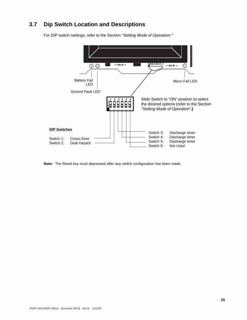
DIP Switches
Switch 1: Cross-ZoneSwitch 2: Dual Hazard
1 2 3 4 5 6ON
Switch 3: Discharge timerSwitch 4: Discharge timerSwitch 5: Discharge timerSwitch 6: Not Used
Slide Switch to "ON" position to selectthe desired options (refer to the Section"Setting Mode of Operation".)
Micro Fail LEDBattery FailLED
Ground Fault LED
3.7 Dip Switch Location and Descriptions
For DIP switch settings, refer to the Section "Setting Mode of Operation."
Note: The Reset key must depressed after any switch configuration has been made.
PDRP-1001/PDRP-1001A Document 50734 Rev B 12/21/97
26
Switch 1Switch 2
Mode #1Single Hazard
Two Zone
Mode #3Dual Hazard
Combined Release
Mode #4Dual HazardSplit Release
Mode #2Single HazardCross Zone
Switch 6
OFFOFF
Outputs 1 and 3- activatedby an alarm on either Zone1 or 2.
Output 2 -activated by awaterflow alarm onZone 3 .
Output 4- activated by asupervisory condition onZone 4.
ONON
Output 1- activated by analarm on either Zone 1 orZone 2 or a waterflowalarm on Zone 3 .
Output 2 -activated by asupervisory condition onZone 4.
Output 3 -activated by analarm on Zone 1 .
Output 4 -activated by analarm on Zone 2 .
ONOFF
Output 1- activated by analarm on either Zone 1or Zone 2 .
Output 2 -activated by awaterflow alarm onZone 3 .
Output 3- activated byalarms on both Zone 1and Zone 2 .
Output 4- activated by asupervisory condition onZone 4.
OFFON
Output 1- activated by analarm on either Zone 1 orZone 2 or a waterflowalarm on Zone 3 .
Output 2 -activated by asupervisory condition onZone 4 .
Output 3 and 4 -activatedby an alarm on either Zone1 or Zone 2.
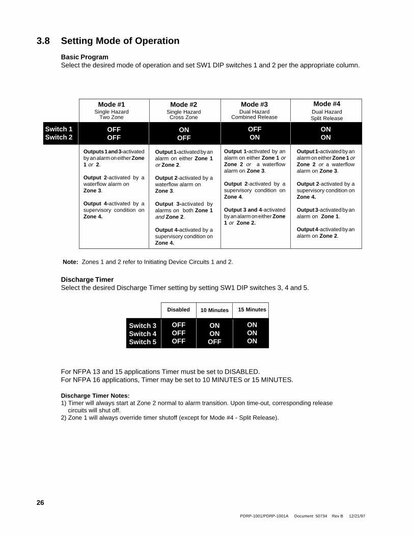
Note: Zones 1 and 2 refer to Initiating Device Circuits 1 and 2.
For NFPA 13 and 15 applications Timer must be set to DISABLED.For NFPA 16 applications, Timer may be set to 10 MINUTES or 15 MINUTES.
Discharge Timer Notes:1) Timer will always start at Zone 2 normal to alarm transition. Upon time-out, corresponding release circuits will shut off.2) Zone 1 will always override timer shutoff (except for Mode #4 - Split Release).
15 Minutes
ONONON
10 Minutes
ONONOFF
Disabled
OFFOFFOFF
Switch 3Switch 4Switch 5
3.8 Setting Mode of Operation
Basic ProgramSelect the desired mode of operation and set SW1 DIP switches 1 and 2 per the appropriate column.
Discharge TimerSelect the desired Discharge Timer setting by setting SW1 DIP switches 3, 4 and 5.

PDRP-1001/PDRP-1001A Document 50734 Rev B 12/21/97
27
a. Two-wire detector heads
b. Four-wire detector heads
c. End of Line Relays
d. Add lines a, b, & c for subtotal
Table A-1: Standby Battery Requirements
The Standby Battery Current figure obtained in Table A - 1 represents the amount of current that must besupplied by the secondary power source (batteries) to sustain control panel operation for one hour.
Note: The control panel will support the installation of one or two optional modules, including two of the same type of module.
Basic Control Panel 88 mAControl panel with AC power off, System Trouble LED and audible trouble sounder on.
If using a 4XZM Zone Relay Module1 [ ] X 8 mA =
If using a 4XTM Transmitter Module, add 11 mA
If using the Reverse Polarity Alarm output, add 5 mA
If using the Reverse Polarity Trouble output, add 5 mA
If using a 4XLM/RZA-4X Driver/Annunciator combination:1
[ ] X 19 mA =
If using a 4XMM Meter Module, add 1 mA
If using the Noti•Fire 911AC DACT, add 30 mA
X =
X =
X 25.0 mA =
Add last column for Standby Battery Current : and continue to Table A-2.
+Place subtotal here
TotalCurrent
Numberin use
DeviceCurrent
(see Appendix B for data)
Appendix A: Power Calculations

PDRP-1001/PDRP-1001A Document 50734 Rev B 12/21/97
28
Notes:1) Alarm amp-hours assumes a maximum system draw of 3 amps in alarm for 5 minutes (0.25 amp/hour) or for
10 minutes(0.5 amp/hour).
2) NFPA 72 Central Station and Local and Proprietary Fire Alarm Systems require 24 hours of standby.3) NFPA 72 Auxiliary and Remote Station Fire Alarm Systems require 60 hours of standby.
5) The battery charger in this panel will charge a maximum of 15 amp/hour of batteries within 48 hours (7 amp/hour minimum). Batteries larger than 12 amp/hour will require a UL listed battery cabinet (e.g. Notifier BB-17).
Table A-2: Ampere-Hour Calculations
amps X hours =
Enter 0.25 for 5 minutes in alarm or0.5 for 10 minutes in alarm
Add Standby and Alarm amp/hours =
Select a battery with an equal or greater amp/hour rating than the figure obtained in Table A-2.Batteries must be lead-acid type.
PS-1270 12-volt, 7 amp/hour (two required)PS-12120 12-volt, 12 amp/hour (two required)
Standbyamp/hours
Alarmamp/hours
Total amp/hoursneeded
+
Standby Battery Current Standby TimeConvert the total from Table 1 24, 60, or 90 hoursto amps and enter here

PDRP-1001/PDRP-1001A Document 50734 Rev B 12/21/97
29
ledoM epyT )Am(tnerruC089-MF elgnis,tnuoMroolF 86
699-MF gniriWecafruS 86
899-MF gniriWdelaecnoC 86
A051HD tnuoMroolF 69
A451HD tnuoMhsulF 69
A851HD tnuoMecafruS 69
24 VDC Door Holders
UL Listed 24 VDC Relays
RODNEV LEDOM )Am(TNERRUC
rosneSmetsyS B617-77A 02
&stcudorPriADTL,slortnoC
C/101-RMC/102-RM
5153
FM-Approved Releasing Devices(Notifier's RP-1001)
Solenoid Group [A]Skinner solenoid valve Model LV2LBX25, 24 VDC, 11 WATTS,458 mA, 1/2 in. NPS, 5/8 in. orifice.
Solenoid Group [B] These valves are interchangeable.ASCO solenoid valve Model T8210A107, 24 VDC, 16.8 Watts,700 mA, 1/2 in. NPS, 5/8 in. orifice.ASCO solenoid valve Model R8210A107, 24 VDC, 16.8 Watts,700 mA, 1/2 in. NPS, 5/8 in. orifice.ASCO solenoid valve Model 8210A107, 24 VDC, 16.8 Watts, 700mA, 1/2 in. NPS, 5/8 in. orifice.
Solenoid Group [C]Star Sprinkler Corp. Solenoid P/N 5550, 24 VDC, part of ModelD deluge valve.
Kidde-Fenwal Electric Control HeadP/N 890181; 24V, 2.0AmpsKidde-Fenwal Electric Control HeadP/N 899175; 24V, 2.0AmpsKidde-Fenwal Electric Control Head Stackable (XP)P/N 48650001; 24V, 0.2AmpsKidde-Fenwal Electric and Cable Op Control Head (XP)P/N 897494; 24V, 1.5Amps, 33 Watts
Refer to the FM approval guide for automatic water controlvalves which are compatible with solenoids listed above.
UL Listed Four-Wire Smoke Detectors
esaB/rotceteDekomS epyTrotceteDybdnatSxaM)Am(tnerruC
tnerruCmralA)Am(
4242rosneSmetsyS cirtceleotohP 01.0 14
HT4242rosneSmetsyS cirtceleotohP 01.0 14
1542rosneSmetsyS cirtceleotohP 01.0 93
)esaBB204B/htiw(HT1542rosneSmetsyS cirtceleotohP 01.0 93
4241rosneSmetsyS noitazinoI 01.0 14
)esaBB204B/w(1541rosneSmetsyS noitazinoI 01.0 93
2142rosneSmetsyS cirtceleotohP 21.0 77
TA2142rosneSmetsyS cirtceleotohP 21.0 85
HT2142rosneSmetsyS cirtceleotohP 21.0 77
BT42/2132rosneSmetsyS cirtceleotohP 21.0 05
PL211BrosneSmetsyS esaB 21.0 63
PL411BrosneSmetsyS esaB ----- -----
B404BrosneSmetsyS esaB ----- -----
4246rosneSmetsyS maeBdetcejorP 01 4.82
ICDCA004HDrosneSmetsyS tcuDnoitazinoI 52 59
PCDCA004HDrosneSmetsyS tcuDcirtceleotohP 52 59
42/2111rosneSmetsyS noitazinoI 50.0 05
42/2112rosneSmetsyS cirtceleotohP 50.0 05
B42/2112rosneSmetsyS cirtceleotohP 50.0 56
T42/2112rosneSmetsyS 531/wcirtceleotohP o lamrehT 50.0 05
BRST42/2112rosneSmetsyS531/wcirtceleotohP o lamrehT
yaleRyrosivrepuS51 54
Appendix B: Device Compatibility

PDRP-1001/PDRP-1001A Document 50734 Rev B 12/21/97
30
ROSNESMETSYS detaR²egatloV
RWFCD
deretliFCD
rednuoScinortcelED42/21-AMrosneSmetsyS CDV42 37 64
ebortS42SSrosneSmetsyS CDV42 * 03
ebortSOL42SSrosneSmetsyS CDV42 54 52
)egieb-CBOL42SS(ebortSgnilieCCOL42SSrosneSmetsyS CDV42 54 52
ebortSM42SSrosneSmetsyS CDV42 521 57
ebortSgnilieCCM42SSrosneSmetsyS CDV42 521 57
ebortS/rednuoScinortcelED42SSAMrosneSmetsyS CDV42 811 17
ebortS/rednuoScinortcelEOL42SSAMrosneSmetsyS CDV42 811 17
ebortS/rednuoSgnilieCcinortcelECOL42SSAMrosneSmetsyS CDV42 811 17
snelogeuFhtiwebortS/rednuoScinortcelEALOL42SSAMrosneSmetsyS CDV42 811 17
ebortS/rednuoScinortcelEM42SSAMrosneSmetsyS CDV42 891 121
ebortS/rednuoSgnilieCcinortcelECM42SSAMrosneSmetsyS CDV42 891 121
rednuoSR004AProsneSmetsyS CDV42 * 51
ebortSno-ddAOL42SProsneSmetsyS CDV42 54 52
ebortSgnilangiSADA5142SSrosneSmetsyS CDV42 09 57
ebortSgnilangiSADA5742SSrosneSmetsyS CDV42 002 071
ebortSgnilangiSADA01142SSrosneSmetsyS CDV42 542 012
ebortSgnilangiSADA575142SSrosneSmetsyS CDV42 021 39
tiucriC.hcnyShtiwebortSgnilangiSSADA5142SSrosneSmetsyS CDV42 521 601
tiucriC.hcnyShtiwebortSgnilangiSSADA575142SSrosneSmetsyS CDV42 081 511
ebortSgnilangiS/rednuoSADA5142SSAMrosneSmetsyS CDV42 361 121
ebortSgnilangiS/rednuoSADA5742SSAMrosneSmetsyS CDV42 372 612
ebortSgnilangiS/rednuoSADA01142SSAMrosneSmetsyS CDV42 813 652
ebortSgnilangiS/rednuoSADA575142SSAMrosneSmetsyS CDV42 391 931
.tkC.hcnyS/webortSgnilangiS/rednuoSSADA5142SSAMrosneSmetsyS CDV42 361 121
.tkC.hcnyS/webortSgnilangiS/rednuoSSADA575142SSAMrosneSmetsyS CDV42 391 931
ebortS/rednuoS-iniMADA5142SProsneSmetsyS CDV42 011 09
ebortS/rednuoS-iniMADA5742SProsneSmetsyS CDV42 531 801
ebortS/rednuoS-iniMADA575142SProsneSmetsyS CDV42 531 801
ebortS/rednuoS-iniMADA01142SProsneSmetsyS CDV42 042 522
UL Listed Notification AppliancesControl panels supplying Special Application (FWR, Filtered) power must use the notification appliances, relays or doorholders listed in the corresponding tables.
Notes:1) All currents are in Milliamperes and worst case average.2) Nominal Operating voltage.3) Refer to installation instructions for more information.4) * Contact manufacture for currents.

PDRP-1001/PDRP-1001A Document 50734 Rev B 12/21/97
31
Notes:1) All currents are in Milliamperes and
worst case average.2) Nominal Operating voltage.3) Refer to installation
instructions for more information.4) * Contact manufacture for currents.
UL Listed Notification AppliancesControl panels supplying Special Application (FWR, Filtered) power must use the notification appliances, relays or doorholders listed in the corresponding tables.
ROSNESMETSYS detaR²egatloV
RWFCD
deretliFCD
ebortSgnilangiS/rekaepSADA5142R1PSrosneSmetsyS CDV42 09 57
ebortSgnilangiS/rekaepSADA5742R1PSrosneSmetsyS CDV42 002 071
ebortSgnilangiS/rekaepSADA01142R1PSrosneSmetsyS CDV42 542 012
ebortSgnilangiS/rekaepSADA575142R1PSrosneSmetsyS CDV42 021 39
ebortSgnilangiS/rekaepSADA5142R4VrosneSmetsyS CDV42 09 57
ebortSgnilangiS/rekaepSADA5742R4VrosneSmetsyS CDV42 002 071
ebortSgnilangiS/rekaepSADA01142R4VrosneSmetsyS CDV42 542 012
ebortSgnilangiS/rekaepSADA575142R4VrosneSmetsyS CDV42 021 39
ellirgdnuor"8,ebortS/rekaepSgnilieCCOL42W001PSrosneSmetsyS CDV42 54 52
ellirgerauqs"5,ebortS/rekaepSOL42R101PSrosneSmetsyS CDV42 54 52
ellirgerauqs"5,ebortS/rekaepSM42R101PSrosneSmetsyS CDV42 521 57
ellirgdnuor"8,ebortS/rekaepSgnilieCCM42W001PSrosneSmetsyS CDV42 521 57
enoTlacinahceMhtiwnroHtrelAitluMHE42/21AMrosneSmetsyS CDV42/CDV21 46/02 34/83
ebortS/enoTlacinahceMhtiwnroHtrelAitluMOL42HEAMrosneSmetsyS CDV42 901 86
ebortS/enoTlacinahceMhtiwnroHtrelAitluMCOL42HEAMrosneSmetsyS CDV42 901 86
ebortS/enoTlacinahceMhtiwnroHtrelAitluMALOL42HEAMrosneSmetsyS CDV42 351 69
ebortS/enoTlacinahceMhtiwnroHtrelAitluMM42HEAMrosneSmetsyS CDV42 981 811
ebortS/enoTlacinahceMhtiwnroHtrelAitluMCM42HEAMrosneSmetsyS CDV42 981 811
ebortS/enoTlacinahceMhtiwnroHtrelAitluMADA5121HEAMrosneSmetsyS CDV21 042 191
ebortS/enoTlacinahceMhtiwnroHtrelAitluMADA575121HEAMrosneSmetsyS CDV21 013 642
ebortS/enoTlacinahceMhtiwnroHtrelAitluMADA5142HEAMrosneSmetsyS CDV42 872 612
ebortS/enoTlacinahceMhtiwnroHtrelAitluMADA5742HEAMrosneSmetsyS CDV42 372 612
ebortS/enoTlacinahceMhtiwnroHtrelAitluMADA575142HEAMrosneSmetsyS CDV42 343 172
ebortS/enoTlacinahceMhtiwnroHtrelAitluMADA01142HEAMrosneSmetsyS CDV42 813 652
ebortS/enoTlacinahceMhtiwnroHtrelAitluMSADA5142HEAMrosneSmetsyS CDV42 891 251
ebortS/enoTlacinahceMhtiwnroHtrelAitluMSADA575142HEAMrosneSmetsyS CDV42 352 142
nroHtrelArtcepS21HrosneSmetsyS CDV21 52 41
nroHtrelArtcepS24HrosneSmetsyS 3 CDV42 24 73
ebortStrelArtcepS5121SrosneSmetsyS CDV21 951 331
ebortStrelArtcepS575121SrosneSmetsyS CDV21 281 861
ebortStrelArtcepS5142SrosneSmetsyS 3 CDV42 241 38
ebortStrelArtcepS575142SrosneSmetsyS 3 CDV42 231 67
ebortStrelArtcepS5742SrosneSmetsyS 3 CDV42 071 541
ebortStrelArtcepS01142SrosneSmetsyS 3 CDV42 022 961
ebortS/nroHtrelArtcepS5121ProsneSmetsyS CDV21 371 441
ebortS/nroHtrelArtcepS575121ProsneSmetsyS CDV21 691 971
ebortS/nroHtrelArtcepS5142ProsneSmetsyS 3 CDV42 561 49
ebortS/nroHtrelArtcepS575142ProsneSmetsyS 3 CDV42 771 111
ebortS/nroHtrelArtcepS5742ProsneSmetsyS 3 CDV42 512 081
ebortStrelArtcepS01142ProsneSmetsyS 3 CDV42 562 412
ADA5121PRrosneSmetsyS A etalPebortStiforteR CDV21 002 071
ADA575121PRrosneSmetsyS A etalPebortStiforteR CDV21 042 552
ADA5142PRrosneSmetsyS A etalPebortStiforteR CDV42 09 57
ADA575142PRrosneSmetsyS A etalPebortStiforteR CDV42 021 39
ADA5742PRrosneSmetsyS A etalPebortStiforteR CDV42 002 071
ADA01142PRrosneSmetsyS A etalPebortStiforteR CDV42 542 012
trelArtcepS42HrosneSmetsyS CDV42 24 73
ebortStrelArtcepS5142SrosneSmetsyS 3 CDV42 241 38
ebortStrelArtcepS575142SrosneSmetsyS 3 CDV42 231 67
ebortStrelArtcepS5742SrosneSmetsyS 3 CDV42 071 541
ebortStrelArtcepS01142SrosneSmetsyS 3 CDV42 022 961
ebortS/nroHtrelArtcepS5142SrosneSmetsyS 3 CDV42 561 49
ebortS/nroHtrelArtcepS575142SrosneSmetsyS 3 CDV42 771 111
ebortS/nroHtrelArtcepS5742SrosneSmetsyS 3 CDV42 512 081
ebortS/nroHtrelArtcepS01142ProsneSmetsyS 3 CDV42 562 412

PDRP-1001/PDRP-1001A Document 50734 Rev B 12/21/97
32
forebmuNrePsrotceteD
enoZ
ledoM.teD
DIrotceteD
epyTledoMesaB
esaBDI
ybdnatStnerruC
)Au(1001-PRDP
0041rosneSmetsyS A noitazinoI a/n a/n 001 02
1541rosneSmetsyS A noitazinoI B604B/B104B A 021 1/51
HD1581rosneSmetsyS A noitazinoI CD1581HD A 021 51
0042rosneSmetsyS A cirtceleotohP a/n a/n 021 51
TIA0042rosneSmetsyS A nroH/lamrehTdetalosI/otohP a/n a/n 021 1
TA0042rosneSmetsyS A nroH/lamrehT/otohP a/n a/n 021 1
HT0042rosneSmetsyS A lamrehT/otohP a/n a/n 021 51
1542rosneSmetsyS A cirtceleotohP B604B/B104B A 021 1/51
HT1542rosneSmetsyS A lamrehT/otohP B604B/B104B A 021 1/51
HD1582rosneSmetsyS A cirtceleotohP CD1582HD A 021 51
HD1541rosneSmetsyS A noitazinoI 004-HD A 021 51
1542rosneSmetsyS A cirtceleotohP 004-HD A 021 51
T0032rosneSmetsyS A lamrehT/otohP a/n a/n 021 51
0081rosneSmetsyS A noitazinoI a/n a/n 001 a/n
B1581rosneSmetsyS A noitazinoI B101B A 021 a/n
B1581rosneSmetsyS A noitazinoI B701B A 021 a/n
0082rosneSmetsyS A cirtceleotohP a/n a/n 021 a/n
HT0082rosneSmetsyS A lamrehT/otohP a/n a/n 021 a/n
B1582rosneSmetsyS A cirtceleotohP B101B A 021 a/n
B1582rosneSmetsyS A cirtceleotohP B701B A 021 a/n
HTB1582rosneSmetsyS A lamrehT/otohP B101B A 021 a/n
HTB1582rosneSmetsyS A lamrehT/otohP B701B A 021 a/n
1511rosneSmetsyS A noitazinnoI PL611B/PL011B/104B A 021 1/51/51
1512rosneSmetsyS A cirtceleotohP PL611B/PL011B/104B A 021 1/51/51
UL Listed, Compatible Two-Wire Smoke Detectors for Notifier Control Panels

PDRP-1001/PDRP-1001A Document 50734 Rev B 12/21/97
33
PDRP-1001/PDRP-1001A Control Panel containing the main control board, cabinet (backbox and door),main supply transformer and power supply.
Batteries (refer to Appendix A for Standby Power Requirements).
Initiating Devices - connected to one of the control panel's Initiating Device Circuits.
Notification Appliances - connected to one of the control panel's Notification Appliance Circuits.
Releasing Devices - connected to one of the control panel's Releasing Circuits.
The following additional equipment is needed for compliance with the NFPA standards listed below:
NFPA 72 Signaling Systems for Central Station Service (Protected Premises Unit)NOTI-FIRE 911AC DACT* - for connection to a compatible listed Central Station DACR or ProtectedPremises Receiving Unit. This unit must be installed as outlined in Figure C-1A.
NFPA 72 Auxiliary Fire Alarm System4XTM Transmitter Module for connection to a compatible listed Local Energy Municipal Box. This unit mustbe installed as outlined in Figure C-2.
NFPA 72 Remote Station Fire Alarm System4XTM Transmitter Module for connection to the Fire•Lite RS82-9 Remote Station Receiver. See FigureC-3 for installation instructions for this unit...
OR
NOTI-FIRE 911AC DACT * or Fire•Lite MS-5012- For connection to a compatible listed remote stationDACR. This unit must be installed as outlined in Figure C-1A.
* Applications which require the NOTI-FIRE 911AC or the Potter EFT-C are not FM approved.
Appendix C: NFPA Standard-Specific Requirements
The fire control panel has been designed for use in commercial, industrial, and institutional applications andmeets the requirements for service under the National Fire Protection Association (NFPA) Standardsoutlined in this appendix. The minimum system components required for compliance with the appropriateNFPA standard are listed below.

PDRP-1001/PDRP-1001A Document 50734 Rev B 12/21/97
34
Figure C-1A: NFPA 72 Signaling Systems for Central Station Service(ProtectedPremises Unit) and Remote Station Protective Service
NOTI-FIRE 911AC DACT* - for connection to a Central Station Receiver or Protected Premises ReceivingUnit. This unit must be installed as illustrated below. For additional information on the 911AC, refer todocument 74-06200-005.
All connections between the FACP and 911AC must be in conduit, less than 20' in length in the same room.* This application using the NOTI-FIRE 911AC is not FM approved.
Note on STD DACT:Place jumper over pins 2 & 3,marked DACT, whenemploying a DACT. Thisdirects the control panel totransmit all trouble conditionsexcept AC LOSS.
draobrehtoM CA119
mralA 1-3BT 7dna6
yllamronnepo
stcatnoc
3-3BT 9dna8
elbuorT 4-3BT 01
yllamronnepo
stcatnoc
6-3BT 11
yrosivrepuS 21-1BTMZX4 21
yllamronnepo
stcatnoc
ot6-3BTrepmuj01-1BTMZX4
STD DACTJP-1
To CentralStation
Supervisory
Alarm

PDRP-1001/PDRP-1001A Document 50734 Rev B 12/21/97
35
Figure C-1B: NFPA 72 Signaling Systems for Central Station Service
Program the Fire•Lite MS-5012 for slave application. Reference the Installation Manual for additionalinformation.
TBTB4TB3
AC Wiring for DACT/FACPmust be connected to thesame circuit.
draobrehtoM 2105-SM
mralA 1-3BT 2-2BT
3-3BT 1-2BT
elbuorT 4-3BT 4-2BT
6-3BT 3-2BT
yrosivrepuS 01-1BTMZX4 01-2BT
21-1BTMZX4 9-2BT
7

PDRP-1001/PDRP-1001A Document 50734 Rev B 12/21/97
36
Figure C-2: NFPA 72 Auxiliary Fire Alarm System
All connections are power limited and supervised. This application is not suitable for separate transmissionof sprinkler supervisory or trouble conditions.
Note: Maximum loop resistance allowed for wiring from control panel to Municipal Box is 3 ohms.
NOTIFIER 4XTMTransmitter Module(activated polarities
shown)
+
-
Municipal Box Circuit
GamewellModel M34-56Local EnergyMunicipal Box6
7
+ -
Note: Municipal Box wiring can leave the building.

PDRP-1001/PDRP-1001A Document 50734 Rev B 12/21/97
37
Figure C-3: NFPA 72 Remote Station Fire Alarm System
Intended for connection to a polarity reversal circuit of a remote station receiving unit having compatibleratings. All connections are power limited and supervised with the exception of the reverse polarity loop.Supervision of the loop is the responsibility of the receiver.
+ - + -
Remote Trouble
Remote Alarm1234
NOTIFIER 4XTMTransmitter Module
(activated polarities shown)
Note: Remote Alarm and Remote Trouble wiring can leave the building.
Fire•Lite RS82-9Remote Station Receiver
UL listed

PDRP-1001/PDRP-1001A Document 50734 Rev B 12/21/97
38
Troubleshooting TableMOTPMYS MELBORP NOITULOS
noDELrewoPCA
noDELelbuortmetsyS
noDELelbuorttiucriC elbuorttiucricecnailppanoitacifitoN
.1 rof3BT(.snoitcennocreporprof2BTkcehCBX4 )slenap
.2 llatsnidnagniriwdleifllaevomeRrofkcehC.tiucrictuptuotaRLEymmud
,)V3.2-lamroN(,tissorcaegatlovyrosivrepus.draobtiucricecalper,tsisrepmelborpfi
.3 gniriwdleiftcennocer,RLEymmuddevomeR,V5-elbuort(;tuptuossorcaegatloverusaemdna
.)V0trohs.4 .ecivedtsaltaRLErofkcehC.5 .gniriwdleifkcehC
nmulocthgirehtfoynAgnihsalfsDELwolley
elbuorttiucricnepoenozgnitaitinI
.1 .snoitcennocreporprof4BTkcehC
.2 dnaelbuortnienozrofgniriwdleifevomeRrofK2.2;V42rofK7.4(RLEymmudllatsni
.draobtiucricecalper,tsisrepmelborpfI.)V21.3 .ecivedtsaltaRLErofkcehC.4 .gniriwdleifkcehC
nmulocthgirehtfoynAnoydaetssDELwolley
elbasidenoZ .1 .launamnoitallatsnikcehC
noDELelbuortrewoP
elbuortyrettaBDELwolleyttaB
no
rognissiMdetcennocsiD
.1 .snoitcennocyrettabkcehC
egamadrowoLyrettab
.1 regrahcssorcaegatlovkcehc,seirettabevomeR,)V21rofV01-8;V42rofV91ot71(tuptuo
.draobtiucricecalperesiwrehto.2 taegatlovyrettaberusaem,seirettabtcennoceR
fo%58nahtsselsiegatlovfI.slanimretyrettab.sruoh84rofegrahcotmehtwolla,egatlovdetar
.3 .seirettabecalper,tsisrepmelborpfI
elbuorttluafdnuorGnoDELwolleyhtraE
.1 dnalenapniammorfgniriwdleifevomeRymmudllatsnI.)dellatsnifi()s(eludomlanoitpo
.)V21rofK2.2;V42rofK7.4(RLE.2 .sdaelyrettabhtobevomeR.3 emitehttatiucricenotcennoc,sraelcelbuortfI
.melborpehttniopnipot.4 .draobtiucricecalper,raelct'nseodelbuortfI
MTX4noDELwolleYno
MTX4.1 1WShctiwstcennocsidxoBlapcinuMevoM.pu
tucrepmuj2TPO,1TPO.1 firepmujecalperro)s(eludomlanoitpollatsnI
.desutonsi)s(eludom
tiucricnepoxoBlapicinuM.1 noitpoxoBlapcinuMfidaolymmudllatsnI
.desut'nsi.2 .gniriwxoBlapcinuMkcehC
nosDELdernmulocthgirehtfoynA gniriwtiucricgnitaitininotrohS.1 fI.RLEllatsnidnagniriwdleifevomeR
deriwyltcerrocniroytluafrofkool,sraelcelbuort.secived
MTX4nohctiwsxoBlapicinuMgnitcennocsiDelbuortaetaerctonseod
t'nsiseludomlanoitporofrepmuJtuc
.1 .2TPOro1TPOrepmujdetaicossatuC
,mralarofetavitcat'nseodDELdetaicossa:MZX4snoitidnocyrosivrepusroelbuort
elbuorteludomlanoitpO.1 .dellatsniylreporpsieludomerusekaM.2 ehtotMZX4no1WShctiwselbasidevoM
.tfel
roelbuort,mralarofdnuost'nseodozeipX4-AZRsnoitidnocyrosivrepus
MLX4.1 nodellatsnisieludomMLX4tahterusekaM
.8Jdna7J.2 .gniriwdleifkcehC
noDELwolleyliaForciM degamadrossecorporciM .1 .draobtiucricecalpeR
noyatssDELX4-AZRllAroirpdevomert'nsawrewoP
noitallatsni.1 .tesermetsystiH
ffoDELrewoPCAnoDELelbuortmetsyS
rewopniamfossoL.1 rof1BT(.)5BT(rewopgnimocnikcehC BX4
)slenap
rekaerbtiucricdegamaD .1 .draobtiucricecalpeR
noDELwolleyliaForciM degamadrossecorporciM .1 .draobtiucricecalpeR

PDRP-1001/PDRP-1001A Document 50734 Rev B 12/21/97
39
NOTES

PDRP-1001/PDRP-1001A Document 50734 Rev B 12/21/97
40
SYSTEM SENSOR® warrants its products to be free from defects in materials andworkmanship for eighteen (18) months from the date of manufacture, under normaluse and service. Products are date stamped at time of manufacture. The sole andexclusive obligation of SYSTEM SENSOR® is to repair or replace, at its option, free ofcharge for parts and labor, any part which is defective in materials or workmanshipunder normal use and service. For products not under SYSTEM SENSOR® manufacturingdate-stamp control, the warranty is eighteen (18) months from date of original purchaseby SYSTEM SENSOR®'s distributor unless the installation instructions or catalog setsforth a shorter period, in which case the shorter period shall apply. This warranty isvoid if the product is altered, repaired or serviced by anyone other than SYSTEM SENSOR®
or its authorized distributors or if there is a failure to maintain the products and systemsin which they operate in a proper and workable manner. In case of defect, phoneSYSTEMS SENSOR'S® toll free number 800-SENSOR2 (736-7672) for a Return Authorizationnumber, send defective units postage prepaid to: SYSTEM SENSOR®, Repair Department,RA #__________, 3825 Ohio Avenue, St. Charles, Il 60174. Please include a notedescribing the malfunction and suspected cause of failure.
This writing constitutes the only warranty made by SYSTEM SENSOR® with respect to itsproducts. SYSTEM SENSOR® does not represent that its products will prevent any loss byfire or otherwise, or that its products will in all cases provide the protection for whichthey are installed or intended. Buyer acknowledges that SYSTEM SENSOR® is not aninsurer and assumes no risk for loss or damages or the cost of any inconvenience,transportation, damage, misuse, abuse, accident or similar incident.
SYSTEM SENSOR® GIVES NO WARRANTY, EXPRESSED OR IMPLIED, OFMERCHANTABILITY, FITNESS FOR ANY PARTICULAR PURPOSE, OR OTHERWISEWHICH EXTEND BEYOND THE DESCRIPTION ON THE FACE HEREOF. UNDERNO CIRCUMSTANCES SHALL SYSTEM SENSOR® BE LIABLE FOR ANY LOSS OF ORDAMAGE TO PROPERTY, DIRECT, INCIDENTAL OR CONSEQUENTIAL, ARISINGOUT OF THE USE OF, OR INABILITY TO USE SYSTEM SENSOR® PRODUCTS.FURTHERMORE, SYSTEM SENSOR® SHALL NOT BE LIABLE FOR ANY PERSONALINJURY OR DEATH WHICH MAY ARISE IN THE COURSE OF, OR AS A RESULTOF, PERSONAL, COMMERCIAL OR INDUSTRIAL USE OF ITS PRODUCTS.
This warranty replaces all previous warranties and is the only warranty made by SYSTEM
SENSOR®. No increase or alteration, written or verbal, of the obligation of this warrantyis authorized.
Limited Warranty
A Division of Pittway3825 Ohio Avenue, St. Charles, Illinois 60174
1-800-SENSOR2, FAX: 630-377-6495