Embed Size (px)
Citation preview

PDR - NCSX Base Support Structure
6 Mar. 2008
F.Dahlgren
J.Rushinski
T.Cruickshank
H.M. Fan
1

2
The charge to the review committee is as follows:
1) Has the Systems Requirement Document been prepared? Are interfacesadequately defined in it?
2) Does the design meet the requirements?
3) Are the critical calculations necessary to confirm the design basissound? Has a Failure Modes and Effects Analysis been started?
4) Have the constructability, assembly and installation plans beenadequately addressed?
5) Have the drawings and models been promoted to Preliminary Designrelease level?
6) Have the CDR chits been addressed?
3
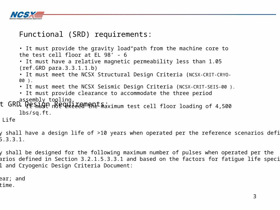
Main Project GRD Design Requirements:
3.2.4.2 Design Life
a. The facility shall have a design life of >10 years when operated per the reference scenarios defined in Section 3.2.1.5.3.3.1.
b. The facility shall be designed for the following maximum number of pulses when operated per the reference scenarios defined in Section 3.2.1.5.3.3.1 and based on the factors for fatigue life specified in the NCSX Structural and Cryogenic Design Criteria Document: • 100 per day; • 13,000 per year; and • 130,000 lifetime.
Functional (SRD) requirements:
• It must provide the gravity load path from the machine core to the test cell floor at EL 98’ - 6”• It must have a relative magnetic permeability less than 1.05 (ref.GRD para.3.3.1.1.b)• It must meet the NCSX Structural Design Criteria (NCSX-CRIT-CRYO-00 ).
• It must meet the NCSX Seismic Design Criteria (NCSX-CRIT-SEIS-00 ).
• It must provide clearance to accommodate the three period assembly tooling.• It must not exceed the maximum test cell floor loading of 4,500 lbs/sq.ft.
4
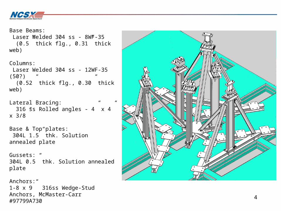
Base Beams: Laser Welded 304 ss - 8WF-35 (0.5” thick flg., 0.31” thick web)
Columns: Laser Welded 304 ss - 12WF-35 (50?) (0.52” thick flg., 0.30” thick web)
Lateral Bracing: 316 ss Rolled angles - 4” x 4” x 3/8”
Base & Top plates: 304L 1.5” thk. Solution annealed plate
Gussets:304L 0.5” thk. Solution annealed plate
Anchors:1-8 x 9” 316ss Wedge-Stud Anchors, McMaster-Carr #97799A730
Weld filler: ER316L-Mn (Stellalloy weld alloy)

5Typical column detail
Typical base weldment detail
Installation will require pre-assembly in the test cell to shim and/or grout level the base frames with surface A & top pedestals, and to locate exact positions of wedge anchors.
Stainless Structurals,LLC is the preferred vendorFor the laser welded beams and rolled angles.

6
QuickTime™ and aTIFF (LZW) decompressor
are needed to see this picture.
QuickTime™ and aTIFF (LZW) decompressor
are needed to see this picture.
Alternate: Hilti HSLG-R - M20: QuickTime™ and aTIFF (LZW) decompressor
are needed to see this picture.

7
FEA Analysis:
Loads and modeling considerations:
Gravity Loads with 1g static vertical downward, B.C.: Symmetry at the floor perimeter & attached @ the test-cell anchor points. Fixed support at basement column bases. Contact elements at the base beam/test-cell floor interface.
Horizontal seismic loading using static 0.15g acceleration per the NCSX/IBC2000 criteria (h~15.3ft, Fp=0.108 x 1.376 = 0.149 ~ 0.15g)*.B.C.: Same as static gravity.
Various static load distributions (inner to outer supports) based on load shifting due to cooldown and EM loading of the MCWF.
* Para 3.1 - NCSX-CRIT-SEIS-(Rev. 0)
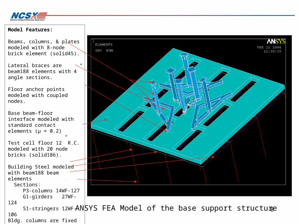
8ANSYS FEA Model of the base support structure
Model Features:
Beams, columns, & plates modeled with 8-node brick element (solid45).
Lateral braces are beam188 elements with 4” angle sections.
Floor anchor points modeled with coupled nodes.
Base beam-floor interface modeled with standard contact elements (µ = 0.2)
Test cell floor 12” R.C. modeled with 20 node bricks (solid186).
Building Steel modeled with beam188 beam elements Sections: P3-columns 14WF-127 G1-girders 27WF-124 S1-stringers 12WF-106Bldg. columns are fixed at the basement floor level and rot. symmetry boundary conditions are employed around the reinforced concrete test cell floor perimeter to approximate the full building structure.
9
Loads Items Unit Model 1R Remarks Comments
Dead load D max mm 3.02E-01 w/o support block Dmax at PF6
DZ mm (-0.292 to 0.0314) w/o support block
Seqv Pa 1.10E+08 PowerGraphics OFF Max.Seqv at sup. Block
Seqv ksi 1.60E+01 PowerGraphics OFF Max.Seqv at sup. Block
OB reaction N 1.53E+05
OB reaction kip 3.43E+01 Total weight
IB reaction N 1.60E+05 3.122E+05 G10 shim on cantilever sup.
IB reaction kip 3.59E+01 7.018E+01 Calculated weight
Dead load D max mm 3.33E-01 w/o support block Dmax at PF6
DL Factor = 1.14 DZ mm (-0.323 to 0.0314) w/o support block
Seqv Pa 9.68E+07 PowerGraphics OFF Max.Seqv at sup. Block
Seqv ksi 1.40E+01 PowerGraphics OFF Max.Seqv at sup. Block
OB reaction N 1.74E+05
OB reaction kip 3.92E+01 Total weight
IB reaction N 1.82E+05 3.561E+05 SS shim on cantilever sup.
IB reaction kip 4.09E+01 8.005E+01
Dead load D max mm 3.34E-01 w/o support block Dmax at PF6
DL Factor = 1.14 DZ mm (-0.324 - 0.0310) w/o support block
Seqv Pa 9.68E+07 PowerGraphics OFF Max.Seqv at sup. Block
Seqv ksi 1.40E+01 PowerGraphics OFF Max.Seqv at sup. Block
OB reaction N 1.82E+05
OB reaction kip 4.09E+01 Total weight
IB reaction N 1.74E+05 3.559E+05 G10 shim on cantilever sup.
IB reaction kip 3.91E+01 8.001E+01
EM load D max mm 2.793 w/o support block Type C modular coil
DZ mm (-0.993 - 1.359) w/o support block
Seqv Pa 4.05E+08 PowerGraphics OFF MCWF flange shim
Seqv ksi 5.87E+01 PowerGraphics OFF
OB reaction N 6.61E+04
OB reaction kip 1.49E+01 Total weight
IB reaction N -6.62E+04 -9.900E+01 ss shim on cantilever sup.
IB reaction kip -1.49E+01 -2.226E-02
DL & EM D max mm 2.766 w/o support block Dmax at MC type C
DL Factor = 1.14 DZ mm (-1.152 - 1.199) w/o support block
Seqv Pa 4.05E+08 PowerGraphics OFF at TF shim?, others 2.51E8
Seqv ksi 5.87E+01 PowerGraphics OFF
OB reaction N 2.40E+05
OB reaction kip 5.40E+01 Total weight
IB reaction N 1.16E+05 3.558E+05 G10 shim on cantilever sup.
IB reaction kip 2.60E+01 7.999E+01
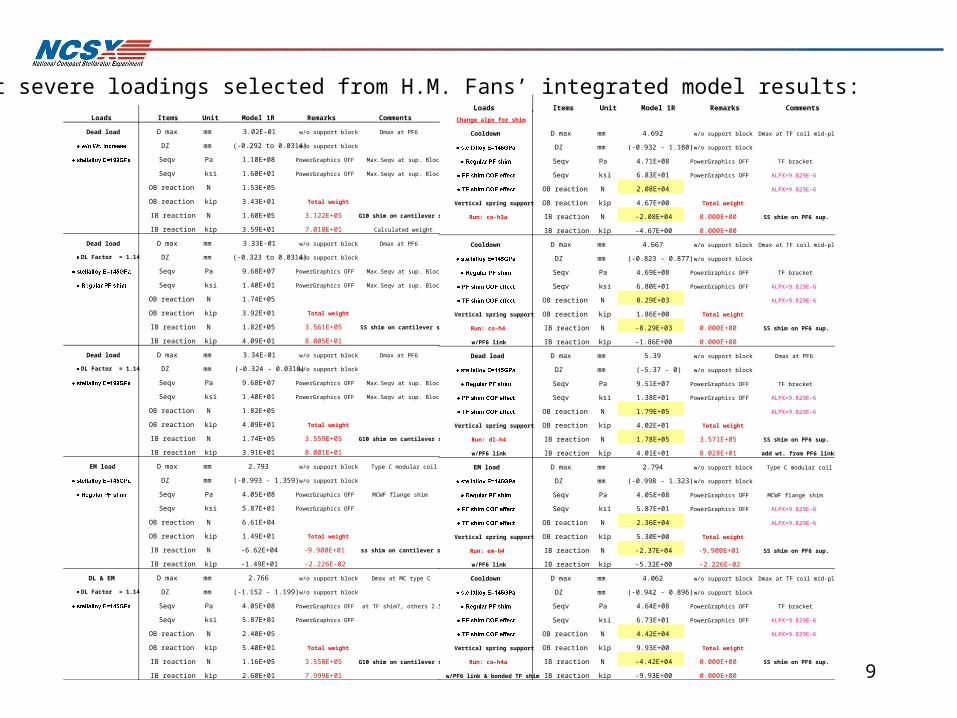
Most severe loadings selected from H.M. Fans’ integrated model results: Change alpx for shim
Cooldown D max mm 4.692 w/o support block Dmax at TF coil mid-plane
DZ mm (-0.932 - 1.180) w/o support block
Seqv Pa 4.71E+08 PowerGraphics OFF TF bracket
Seqv ksi 6.83E+01 PowerGraphics OFF ALPX=9.829E-6
OB reaction N 2.08E+04 ALPX=9.829E-6
Vertical spring support OB reaction kip 4.67E+00 Total weight
Run: co-h3a IB reaction N -2.08E+04 0.000E+00 SS shim on PF6 sup.
IB reaction kip -4.67E+00 0.000E+00
Cooldown D max mm 4.667 w/o support block Dmax at TF coil mid-plane
DZ mm (-0.823 - 0.877) w/o support block
Seqv Pa 4.69E+08 PowerGraphics OFF TF bracket
Seqv ksi 6.80E+01 PowerGraphics OFF ALPX=9.829E-6
OB reaction N 8.29E+03 ALPX=9.829E-6
Vertical spring support OB reaction kip 1.86E+00 Total weight
Run: co-h4 IB reaction N -8.29E+03 0.000E+00 SS shim on PF6 sup.
w/PF6 link IB reaction kip -1.86E+00 0.000E+00
Dead load D max mm 5.39 w/o support block Dmax at PF6
DZ mm (-5.37 - 0) w/o support block
Seqv Pa 9.51E+07 PowerGraphics OFF TF bracket
Seqv ksi 1.38E+01 PowerGraphics OFF ALPX=9.829E-6
OB reaction N 1.79E+05 ALPX=9.829E-6
Vertical spring support OB reaction kip 4.02E+01 Total weight
Run: dl-h4 IB reaction N 1.78E+05 3.571E+05 SS shim on PF6 sup.
w/PF6 link IB reaction kip 4.01E+01 8.028E+01 add wt. from PF6 links
EM load D max mm 2.794 w/o support block Type C modular coil
DZ mm (-0.998 - 1.323) w/o support block
Seqv Pa 4.05E+08 PowerGraphics OFF MCWF flange shim
Seqv ksi 5.87E+01 PowerGraphics OFF ALPX=9.829E-6
OB reaction N 2.36E+04 ALPX=9.829E-6
Vertical spring support OB reaction kip 5.30E+00 Total weight
Run: em-h4 IB reaction N -2.37E+04 -9.900E+01 SS shim on PF6 sup.
w/PF6 link IB reaction kip -5.32E+00 -2.226E-02
Cooldown D max mm 4.062 w/o support block Dmax at TF coil mid-plane
DZ mm (-0.942 - 0.896) w/o support block
Seqv Pa 4.64E+08 PowerGraphics OFF TF bracket
Seqv ksi 6.73E+01 PowerGraphics OFF ALPX=9.829E-6
OB reaction N 4.42E+04 ALPX=9.829E-6
Vertical spring support OB reaction kip 9.93E+00 Total weight
Run: co-h4a IB reaction N -4.42E+04 0.000E+00 SS shim on PF6 sup.
w/PF6 link & bonded TF shim IB reaction kip -9.93E+00 0.000E+00
Loads Items Unit Model 1R Remarks Comments

10
Static Load Summary:
Loading Outboard Z load (kips) Inboard Z load (kips)
Gravity Only -40.01 -40.02
EM unbonded (w/link, corrected Alpha, etc.)
-5.3 +5.3
Cooldown. unbonded(w/link, corrected Alpha, etc.)
-1.86 +1.86
EM bonded (w/link, corrected Alpha, etc.)
-6.63 +6.63
Cooldown. bonded (w/link, corrected Alpha, etc.)
-9.93 +9.93
EM load D max mm 2.756 w/o support block Type C modular coil
DZ mm (-1.02 - 1.322) w/o support block
Seqv Pa 4.03E+08 PowerGraphics OFF MCWF flange shim
Seqv ksi 5.85E+01 PowerGraphics OFF ALPX=9.829E-6
OB reaction N 2.95E+04 ALPX=9.829E-6
Vertical spring support OB reaction kip 6.63E+00 Total weight
Run: em-h4a IB reaction N -2.96E+04 -1.000E+02 SS shim on PF6 sup.
w/PF6 link & bonded TF shim IB reaction kip -6.65E+00 -2.248E-02

11
SRSS & Vertical Displacements for Gravity + Cooldown + EM-N
Peak vector sum displacement 0.050”
FEA Results (normal EM ops. unbonded case):
Peak vertical displacement -0.046”
Note Test Cell floor deflects ~ 0.025” (node 6274)

12
FEA Results (normal EM ops. unbonded case):
Tresca Stress contours for Gravity + Cooldown + EM-N
Peak Stress @ Lateral support mounting brackets 11.3 ksi
Average Stress in columns is 4 - 5 ksi
Peak Stress in the base frame is 4 ksi at gussets
Calc. Stress in anchor studs is 4 - 5 ksi
13
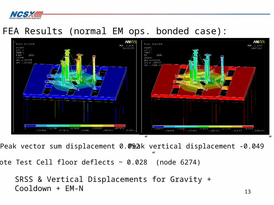
SRSS & Vertical Displacements for Gravity + Cooldown + EM-N
Peak vector sum displacement 0.052” Peak vertical displacement -0.049”
Note Test Cell floor deflects ~ 0.028” (node 6274)
FEA Results (normal EM ops. bonded case):
14
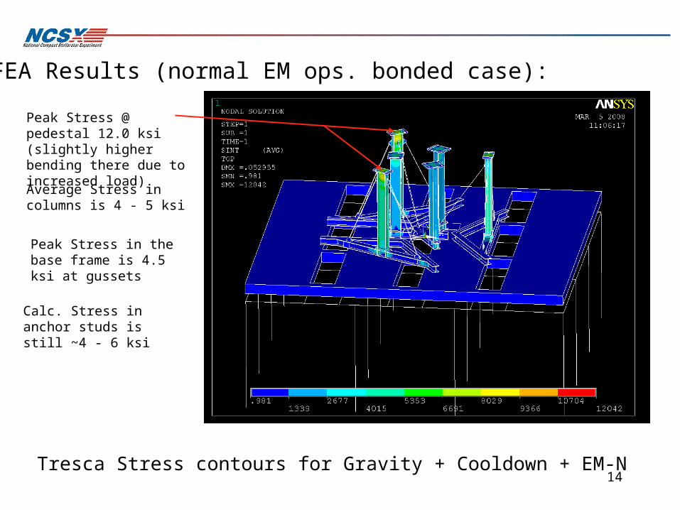
FEA Results (normal EM ops. bonded case):
Tresca Stress contours for Gravity + Cooldown + EM-N
Peak Stress @ pedestal 12.0 ksi (slightly higher bending there due to increased load)
Average Stress in columns is 4 - 5 ksi
Peak Stress in the base frame is 4.5 ksi at gussets
Calc. Stress in anchor studs is still ~4 - 6 ksi

15
FEA Model for seismic runs:
•Concentrated 240 kip (231 slug mass) located at the Stellarator core C.G.
•Static loading 0.15g horizontal, (per the NCSX/IBC2000 criteria).
•Stiff (nearly rigid) beams connect the mass to 6 master nodes just above the support column pedestal level.
•Utilized coupled nodes to master nodes at the sliding low friction surfaces (with the radial DOF uncoupled to simulate the low friction).
• A model analysis was performed todetermine the lowest nutural frequency of the structure.

16
QuickTime™ and aMicrosoft Video 1 decompressorare needed to see this picture.
Modal Analysis Result: 1st flexible mode @ ~1.7 Hz NE-SW (30 deg.)
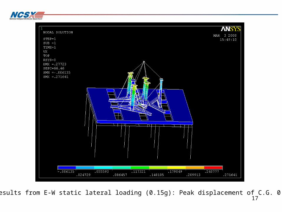
17Results from E-W static lateral loading (0.15g): Peak displacement of C.G. 0.27”
18
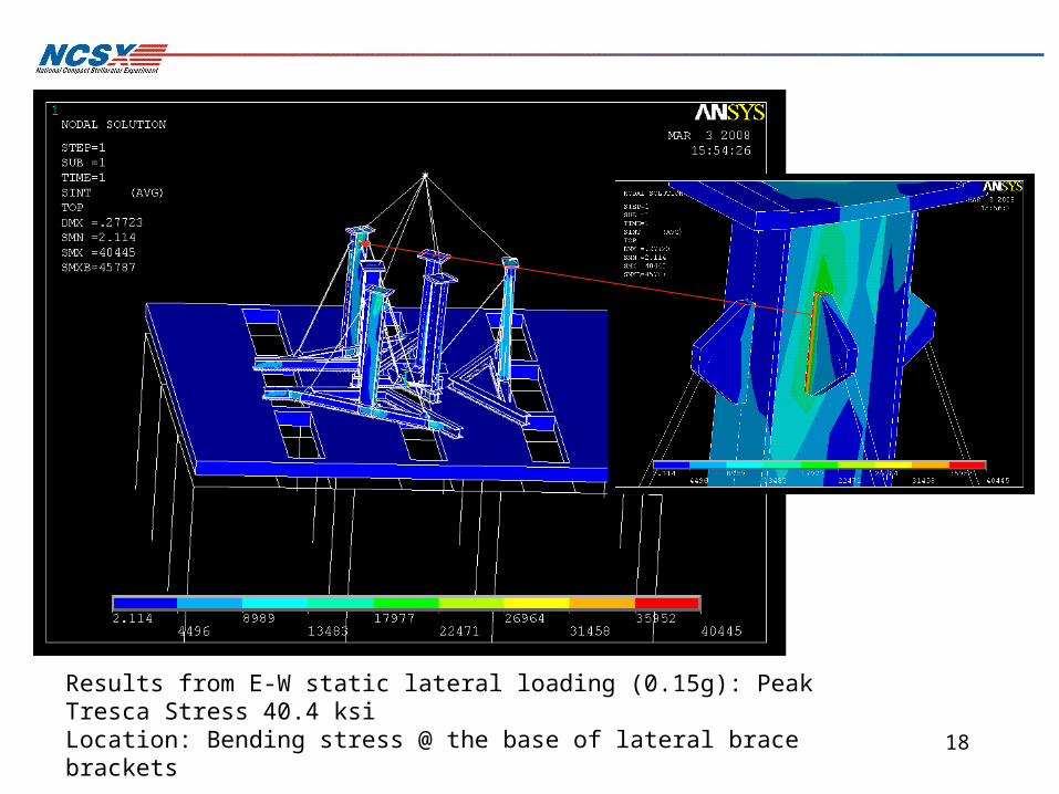
Results from E-W static lateral loading (0.15g): Peak Tresca Stress 40.4 ksiLocation: Bending stress @ the base of lateral brace brackets

19
Results from N-S static lateral loading (0.15g): Peak displacement of C.G. 0.24”

20
Results from N-S static lateral loading (0.15g): Peak Tresca Stress 40.9 ksiLocation: Bending stress @ the base of lateral brace brackets - Modeling issue
21
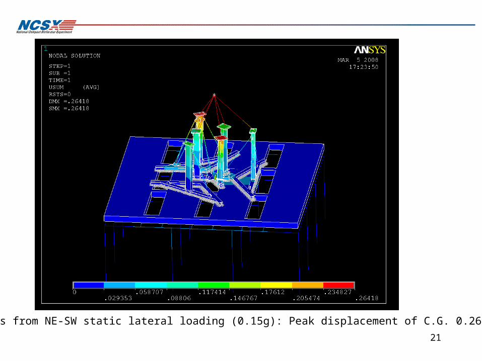
Results from NE-SW static lateral loading (0.15g): Peak displacement of C.G. 0.26”

22Results from NE-SW static lateral loading (0.15g): Peak Tresca Stress 46.8 ksiLocation: Bending stress @ the base of lateral brace brackets - Modeling issue
23
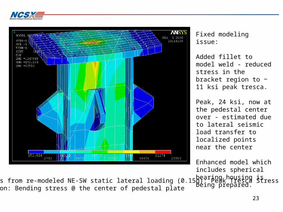
Results from re-modeled NE-SW static lateral loading (0.15g): Peak Tresca Stress 24 ksiLocation: Bending stress @ the center of pedestal plate
Fixed modeling issue:
Added fillet to model weld - reduced stress in the bracket region to ~ 11 ksi peak tresca.
Peak, 24 ksi, now at the pedestal center over - estimated due to lateral seismic load transfer to localized points near the center
Enhanced model which includes spherical bearing housing is being prepared.
24
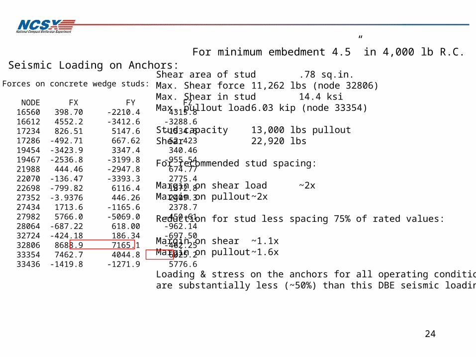
Shear area of stud .78 sq.in.Max. Shear force 11,262 lbs (node 32806)Max. Shear in stud 14.4 ksiMax. pullout load 6.03 kip (node 33354)
Stud capacity 13,000 lbs pulloutShear 22,920 lbs
For recommended stud spacing:
Margin on shear load ~2xMargin on pullout ~2x
Reduction for stud less spacing 75% of rated values:
Margin on shear ~1.1xMargin on pullout ~1.6x
Loading & stress on the anchors for all operating conditionsare substantially less (~50%) than this DBE seismic loading
Forces on concrete wedge studs:
NODE FX FY FZ 16560 398.70 -2210.4 4315.8 16612 4552.2 -3412.6 -3288.6 17234 826.51 5147.6 -1534.6 17286 -492.71 667.62 52.423 19454 -3423.9 3347.4 340.46 19467 -2536.8 -3199.8 -955.54 21988 444.46 -2947.8 674.77 22070 -136.47 -3393.3 2775.4 22698 -799.82 6116.4 1872.8 27352 -3.9376 446.26 2409.3 27434 1713.6 -1165.6 2378.7 27982 5766.0 -5069.0 -450.61 28064 -687.22 618.00 -962.14 32724 -424.18 186.34 -697.50 32806 8688.9 7165.1 -462.25 33354 7462.7 4044.8 6025.2 33436 -1419.8 -1271.9 5776.6
Seismic Loading on Anchors:For minimum embedment 4.5” in 4,000 lb R.C.

25
Design Load Requirements1:
Normal ops.: D + P + L + T + EM-N + IROff-Normal: D + P + L + T + EM-F + IRSeismic: D + P + L + T + FDBE+ IR
Definitions
D - Dead Loads (gravity)P - PressureL - Pre-loadsT - Thermal loadsEM-N Electro-Magnetic Normal Ops.EM-F “ “ Fault conditionsIR - Interaction LoadsFDBE - Design Basis Earthquake LoadDT - Peak column loading
D = 240,000lbs, -40kip per support (nominal)T = -9.93 kip (on O.B. columns), +9.93 kip (I.B. columns)P = 0L = 0 (exception for anchor pre-loading)EM-N = -6.63 (on O.B. columns), + 6.63 kip (I.B. columns)FDBE = 36 kip (for 0.15g static horizontal load)2
vertical acceleration not given in ref.2 (seismic requirements)but 10% used should exceed requirements
IR = 0
1. NCSX-CRIT-CRYO-00
2. NCSX-CRIT-SEIS-00
Comparison with project allowable stresses:
Normal ops. Max stress = 12 ksi - Sm is 16.6 ksi 2/3 25ksi (min.spec yield at R.T.)Seismic Max stress = 24 ksi < Allowable 1.5xSm = 25 ksi for local bendingOff-Normal stress: EM-F not yet defined by project but based on most severe normal EM-N case ± 6.6 ksi and >2 margins on allowable, structure should be capable of handling fault conditions (Project needs to define credible EM-F conditions and stresses to be confirmed by the FDR).

26
Base materials of Structurals meet or exceed ASME BPV code requirements for minimum specified yield at 70 deg.F
ASME ASTM-A240 316L Sy-min. > 25 ksi(assume 25 ksi)
Per NCSX-CRIT-CRYO-00, the stress allowable is the lesser of:
1/3 Sult, or 2/3rd Sy-min.
For all materials specified this will be:
Sm = 16.6 ksi (110 Gpa) @T = 70 oF

27
Column buckling:
Eulers formula:for end condition (d): Fcr = π2 EI / 4L2
WF12 x 35 WF12 x 50L = 98 in L = 98 inIyy = 24.5 in4 Iyy = 56.3 in4
E = 29e6 psi E = 29e6 psiA = 10.3 in2 A = 14.4 in2
Fcr = 182,537 lbs Fcr = 419,463 lbs
Buckling Margins:
For 80 kip loading:
WF12x35 margin = 2.27
WF12x50 margin = 5.2
For 25 ksi min. yield, the buckling stress for a WF12x50 column:
29.1 ksiProbable failure mode is yielding
(Note these values are for columns with no lateral bracing)
28
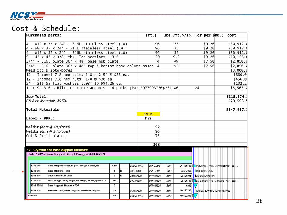
Cost & Schedule:Purchased parts: (ft.) lbs./ft. $/lb. (or per pkg.) cost
4 - W12 x 35 x 24' - 316L stainless steel (LW) 96 35 $9.20 $30,912.004 - W8 x 35 x 24' - 316L stainless steel (LW) 96 35 $9.20 $30,912.004 - W12 x 35 x 24' - 316L stainless steel (LW) 96 35 $9.20 $30,912.005 - 4" x 4" x 3/8" thk. Tee sections - 316L 120 9.2 $9.20 $10,156.803/4" - 316L plate 36" x 48" base hub plate 4 95 $7.50 $2,850.003/4" - 316L plate 36" x 48" top & bottom base column bases 4 95 $7.50 $2,850.00Weld rod & roto-bores $3,000.0012 - Inconel 718 hex bolts 1-8 x 2.5" @ $55 ea. $660.0012 - Inconel 718 hex nuts 1-8 @ $38 ea. $456.0024 - 316 SS flat washers 1.03" ID @$4.26 ea. $102.241 x 9" 316ss Hilti concrete anchors - 4 packs (Part#97799A730) $231.80 24 $5,563.20
Sub-Total: $118,374.24G& A on Materials @25% $29,593.56
Total Materials $147,967.80EMTB
Labor - PPPL: hrs.
Welding (4hrs @ 48 places) 192Welding (4hrs @ 24 places) 96Cut & Drill plates 75
363

29
Coil Structure Peer Review Dahlgren/Reiersen/Dudek
1/17/07 3 Interface with base support structure (p13) should have sliding joints at tops of columns. Columns pinned top and bottom will change elevation when lateral motion occurs. [Perry]
Concur A sliding interface between the top pedestal and spherical bearing housing has been implemented.
Coil Structure Peer Review Dahlgren/Reiersen/Dudek
1/17/07 17 Consider coil fault conditions in the design of the structure. [Dudek] Concur Fault conditions and loads are still TBD
Coil Structure Peer Review Dahlgren/Reiersen/Dudek
1/17/07 1 Coil structure rests on cover plate for an existing building penetration. A structure will be needed to carry loads to the building structure [Perry]
Concur Base Structure spans floor opening and distributes the load to the test cell floor.
Relevant chits from 1/17/07 peer review:

30
Fatigue Considerations:The facility shall be designed for the following maximum number of pulses when operated per the reference scenarios defined in Section 3.2.1.5.3.3.1 and based on the factors for fatigue life specified in the NCSX Structural and Cryogenic Design Criteria Document: • 100 per day; • 13,000 per year; and • 130,000 lifetime.
Max. operational load O.B. columns: 40.1 + 9.93 = 49.94
S max = 14.2 ksi, S min = 12.0 ksi
S mean = 13.1 ksiSeq. = 2.67 ksi
20x life = 2.6e6 cycles
---> 26 ksi limit >> max stress intensity
Conclusion:Fatigue life not a limitingFactor in design
31
The charge to the review committee is as follows:
1) Has the Systems Requirement Document been prepared? Are interfacesadequately defined in it?
2) Does the design meet the requirements?
3) Are the critical calculations necessary to confirm the design basissound? Has a Failure Modes and Effects Analysis been started?
4) Have the constructability, assembly and installation plans beenadequately addressed?
5) Have the drawings and models been promoted to Preliminary Designrelease level?
6) Have the CDR chits been addressed?

32
Seismic Static Load Requirements:For hazardous equipment when Ip > 1 use the followingFp = .4*a.p*Sds*Wp*( 1 + 2*z/h) / (Rp / Ip) Equation 16-67Fp = the seismic force centered at the center of gravity of the componentWp = component operating weighta.p = component amplification select from table 1621.2 or 1621.3
For rigid structures whose natural frequency (Fn) is greater than 16.7 hz use a.p = 1(ref. commentary Figure 1621.1.4)For non rigid structures use a.p = 2.5Fn = 1 / (2*p(W.p / K.p *g)^.5) Component Natural Frequency (1621.3.2)g = Acceleration of gravityK.p = Stiffnes of the component and attachment in terms of load per unit deflection at the center of gravity
Rp = Component response modification factor select from table 1621.2 or 1621.3,Represents the ability of a component to sustain permanent deformations without losing strength ( = 2.5 formost components includes steel and copper , = 1.25 for low deformability elements such as ceramic, glass, or plain concrete)
z = Height in structure above base at point of attachment of component (height above grade)h = Average roof height of structure relative to the base elevationIp = 1 for non hazardous equipment and 1.5 for hazardous equipment or life safety equipment required to functionafter an earthquake, from section 1621.1.6
For NCSX we simplify the equation to :
Fp = .096*a.p*Wp*( 1 + 2*z/h)*Ip / RpWith Basement Elevation = 0’Test Cell Elevation = 13’3”Top of Steel = 55’For the Test Cell Floor z/h = .24For C.G. of machine z/h = 28.5/55 = 0.519a.p. = 1.0 (rigid structure)Ip = 1.5Rp = 2.5
Fp = (.096*(1.0)*(1 + 2*0.519)*1.5/2.5) * Wp = 0.1174 * WpIf a.p. = 2.5 (non-rigid): Fp = (.096*(2.5.0)*(1 + 2*0.519)*1.5/2.5) * Wp = 0.293 * Wp