Embed Size (px)
Citation preview
INSTALLATION, OPERATION
AND SERVICE MANUAL
PDQ PORTABLE DOCK SCISSORS LIFT
P.O. Box 1058 • 1058 West Industrial Avenue • Guthrie, OK 73044-1058 • 405-282-5200
• FAX: 405-282-8105 • www.autoquip.com
Item # 830PDQ Version 1.0
09/2001
TABLE OF CONTENTS Identification and Inspection 3 Dangers, Warnings, and Cautions 4 Label Identification 8 Specifications 11 Lift Blocking Instructions 13 Installation Instructions 15 Operating Instructions 16 Routine Maintenance 19 General Maintenance 21 Replacement Parts List 31 Troubleshooting Analysis 33 Warranty 37
IMPORTANT
Please read and understand this manual prior to installation or operation of this lift. Failure to do so could lead to property damage and/or serious personal injury. If questions arise, call a local representative or Autoquip Corporation at 1-888-811-9876 or 405-282-5200.
PLANNED MAINTENANCE PROGRAM
A local Autoquip representative provides a Planned Maintenance Program (PMP) for this equipment using factory-trained personnel. Call a local representative or Autoquip Corporation at 1-888-811-9876 or 405-282-5200 for more information.
2
IDENTIFICATION & INSPECTION
IDENTIFICATION
When ordering parts or requesting information or service on this lift, PLEASE REFER TO THE MODEL AND SERIAL NUMBER. This information is on a nameplate attached to the leg assembly. Replacement parts are available from a local Autoquip distributor.
INSPECTION
Immediately upon receipt of the lift, a visual inspection should be made to determine that it has not been damaged in transit. Any damage found must be noted on the delivery receipt. In addition to this preliminary inspection, the lift should be carefully inspected for concealed damage. Any concealed damage found that was not noted on the delivery receipt should be reported in writing to the delivering carrier within 48 hours.
The following is a checklist that will aid you in the inspection of this lift:
1. Examine entire unit for any signs of mishandling. Pay special attention to the power unit and pushbuttons.
2. Thoroughly examine all connections, making sure they have not vibrated loose
during transit, and inspect wiring for any signs of damage. 3. After installation, raise the lift and inspect the base frame, platform, scissors
assembly, and cylinder plumbing connections.
3
DANGERS, WARNINGS & CAUTIONS SAFETY ALERTS (Required Reading!) The following SAFETY ALERTS are intended to create awareness of owners, operators, and maintenance personnel of the potential safety hazards and the steps that must be taken to avoid accidents. These same alerts are inserted throughout this manual to identify specific hazards that may endanger uninformed personnel. Identification of every conceivable hazardous situation is impossible. Therefore, all personnel have the responsibility to diligently exercise safe practices whenever exposed to this equipment. ____________________________________________________________
DANGER!
Identifies a hazardous situation that presents the imminent probability of death or of severe personal injury!! _____________________________________________________________
WARNING! Identifies a hazardous situation that has the potential of causing death or serious personal injury.
4
CAUTION!
Identifies a hazardous situation that could lead to the possibility of personal injury of death, and/or may result in equipment damage. _____________________________________________________________
DANGERS, WARNINGS & CAUTIONS
Read and understand this manual and all labels prior to operating or servicing the lift. All labels are provided in accordance with ANSI Z535.4.
DANGER!
Do not work under lift without maintenance device! To avoid personal injury, NEVER go under the lift platform until the load is removed and the scissors mechanism is securely blocked in the open position. See "Lift Blocking Instructions" section.
DANGER!
To avoid personal injury, stand clear of scissors leg mechanism while lift is in motion.
DANGER!
Do not install the lift in a pit unless it has a bevel toe guard or other approved toe protection. A shear point can exist which can cause severe injury to the foot.
DANGER!
HIGH VOLTAGE!! Disconnect and/or lock out the electrical supply to the power unit prior to any maintenance being performed.
5
DANGERS, WARNINGS & CAUTIONS
DANGER!
Extending the platform length or width beyond the factory limit could cause the unit to tip, which could result in personal injury or death.
DANGER! Do not attempt to remove the velocity fuse until the maintenance locks securely support the lift and all hydraulic pressure has been removed from the lifting cylinders and hydraulic hoses. Failure to do so could result in personal injury or death!
WARNING! Do not operate this equipment without handrails and snap chains in place.
WARNING! Under no circumstances should the speed control orifice be removed from the Deltatrol to obtain faster lowering speed. A loaded lift can reach dangerous and destructive speed!!
WARNING! All warning and information decals should be in place as outlined in the “Label Identification” section. If decals are missing or damaged, they should be replaced with new ones. Contact an Autoquip representative for replacements.
6
DANGERS, WARNINGS & CAUTIONS
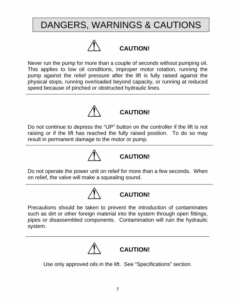
CAUTION! Never run the pump for more than a couple of seconds without pumping oil. This applies to low oil conditions, improper motor rotation, running the pump against the relief pressure after the lift is fully raised against the physical stops, running overloaded beyond capacity, or running at reduced speed because of pinched or obstructed hydraulic lines.
CAUTION! Do not continue to depress the “UP” button on the controller if the lift is not raising or if the lift has reached the fully raised position. To do so may result in permanent damage to the motor or pump.
CAUTION! Do not operate the power unit on relief for more than a few seconds. When on relief, the valve will make a squealing sound.
7
CAUTION! Precautions should be taken to prevent the introduction of contaminates such as dirt or other foreign material into the system through open fittings, pipes or disassembled components. Contamination will ruin the hydraulic system.
CAUTION!
Use only approved oils in the lift. See “Specifications” section.
LABEL IDENTIFICATION
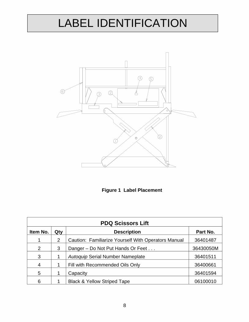
Figure 1 Label Placement
PDQ Scissors Lift Item No. Qty Description Part No.
1 2 Caution: Familiarize Yourself With Operators Manual 36401487
2 3 Danger – Do Not Put Hands Or Feet . . . 36430050M
3 1 Autoquip Serial Number Nameplate 36401511
4 1 Fill with Recommended Oils Only 36400661
5 1 Capacity 36401594
6 1 Black & Yellow Striped Tape 06100010
8
LABEL IDENTIFICATION
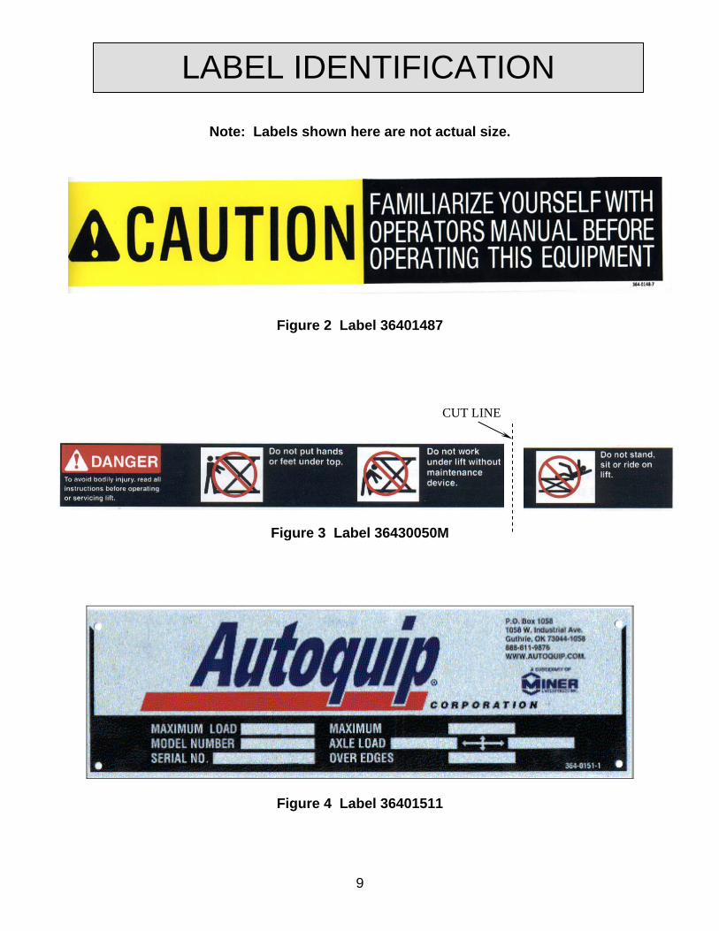
Note: Labels shown here are not actual size.
Figure 2 Label 36401487
CUT LINE
Figure 3 Label 36430050M
Figure 4 Label 36401511
9
10
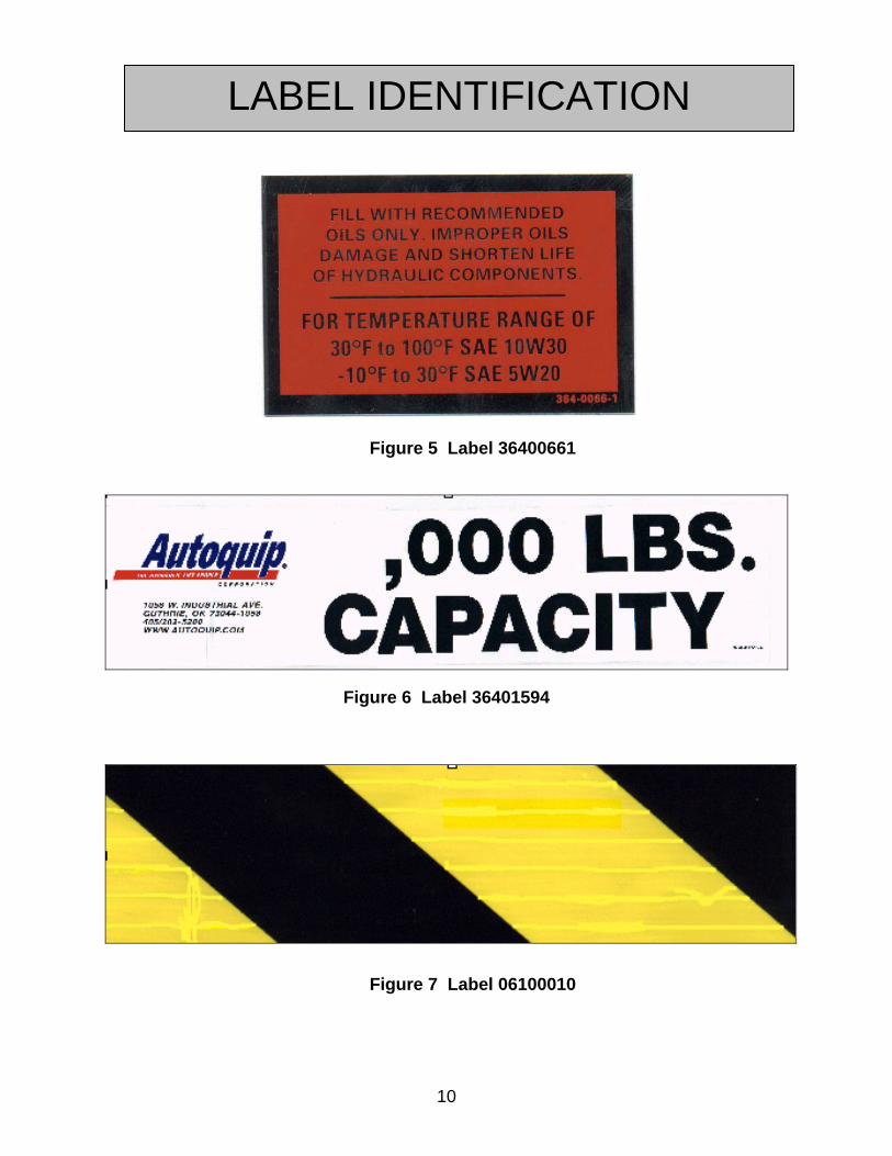
Figure 5 Label 36400661
LABEL IDENTIFICATION
Figure 6 Label 36401594
Figure 7 Label 06100010
*Model Low. Ht. (In.)
Lift Cap (lbs)
Axle Load Capacity
Over Bridge
End (lbs)
Axle Load Capacity Opposite
Bridge End (lbs)
Platform Size (In)
Base Frame Size (In)
Max Travel
(In.)
Ship Wt.
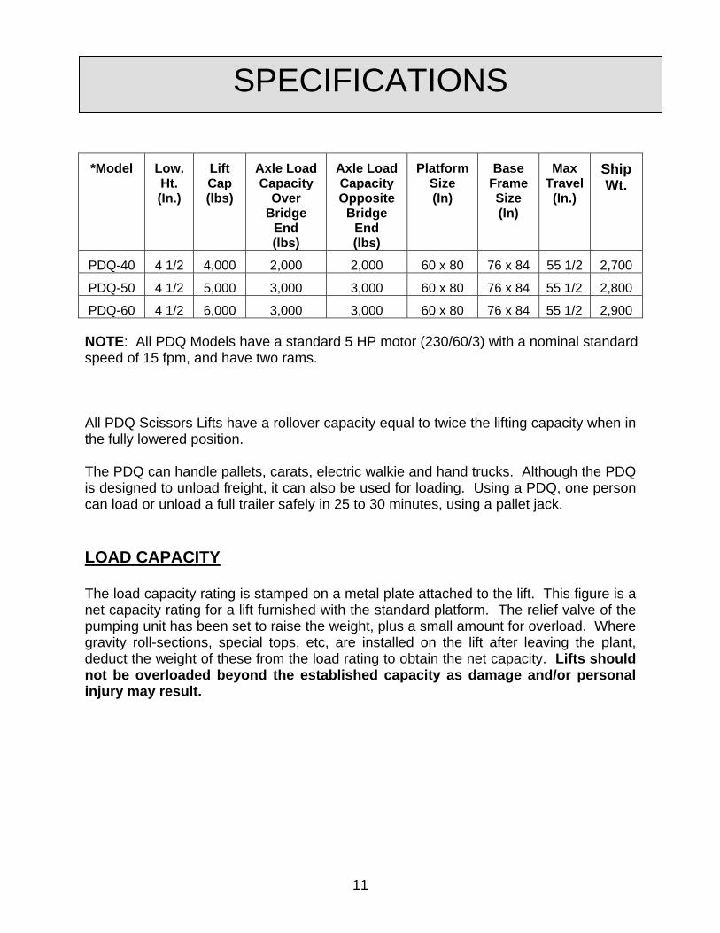
PDQ-40 4 1/2 4,000 2,000 2,000 60 x 80 76 x 84 55 1/2 2,700
PDQ-50 4 1/2 5,000 3,000 3,000 60 x 80 76 x 84 55 1/2 2,800
PDQ-60 4 1/2 6,000 3,000 3,000 60 x 80 76 x 84 55 1/2 2,900
SPECIFICATIONS
NOTE: All PDQ Models have a standard 5 HP motor (230/60/3) with a nominal standard speed of 15 fpm, and have two rams.
All PDQ Scissors Lifts have a rollover capacity equal to twice the lifting capacity when in the fully lowered position. The PDQ can handle pallets, carats, electric walkie and hand trucks. Although the PDQ is designed to unload freight, it can also be used for loading. Using a PDQ, one person can load or unload a full trailer safely in 25 to 30 minutes, using a pallet jack. LOAD CAPACITY The load capacity rating is stamped on a metal plate attached to the lift. This figure is a net capacity rating for a lift furnished with the standard platform. The relief valve of the pumping unit has been set to raise the weight, plus a small amount for overload. Where gravity roll-sections, special tops, etc, are installed on the lift after leaving the plant, deduct the weight of these from the load rating to obtain the net capacity. Lifts should not be overloaded beyond the established capacity as damage and/or personal injury may result.
11
SPECIFICATIONS UNBALANCED LOADING The stabilization provided is basically for balanced loads. If special attachments extend beyond the length and/or width dimensions of the platform, the end and/or side load capacity must be reduced (contact an Autoquip Sales representative). PUMP PRESSURE This lift incorporates a positive displacement pump machined to a high degree of accuracy and specially adapted to requirements of higher-pressure ranges over that of a standard pump. Therefore, standard factory models of the same manufacture cannot replace it.
12
LIFT BLOCKING INSTRUCTIONS
1. Remove all load from the platform. Never block the lift when loaded.
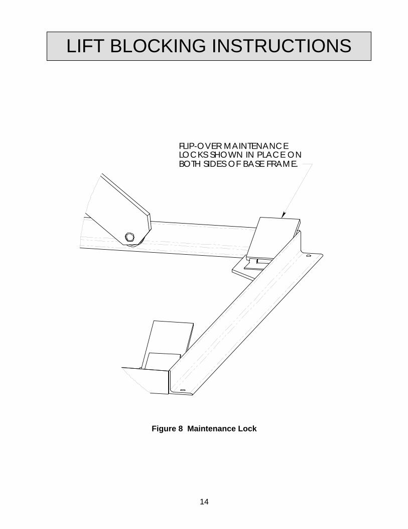
2. Raise the platform sufficiently for the base rollers to rollback past the flip-over maintenance locks, located on the base frame of the lift.
3. Engage both maintenance locks by flipping them into the base frame (see Figure 8). 4. Lower the platform until the base rollers come into contact with and rest against the
maintenance locks. Always hold the “DOWN” switch a few seconds more until all pressure is gone and the platform is supported entirely and safely by the maintenance locks.
5. Always shut off the main electrical switch, when blocked, to prevent someone from
turning it on.
DANGER!
To avoid personal injury, NEVER go under the platform until the load is removed and the lift is securely blocked in the open position.
6. To remove the maintenance locks, raise the platform by activating the “UP” valve to provide sufficient clearance for the removal of the maintenance locks.
DANGER!
Maintenance locks that are bent, damaged, or non-functional must be replaced immediately to avoid personal injury. Contact the Autoquip Service Department for replacement parts and installation instructions.
13
LIFT BLOCKING INSTRUCTIONS
FLIP-OVER MAINTENANCELOCKS SHOWN IN PLACE ONBOTH SIDES OF BASE FRAME.
Figure 8 Maintenance Lock
14
INSTALLATION INSTRUCTIONS The PDQ is easy to install and operation. It is completely self-contained and ready to go as soon as the unit is received. The control is centrally located on the platform to allow operation from either end. All electrical components and wiring are in accordance with the National Electrical Code. Loads can be quickly rolled over the hinged throw-over bridge onto the platform. The bridge automatically rises into the up position as the platform lowers, serving as a wheel chock to help eliminate the danger of shifting loads. In the lowered position, the platform is 4 ½” from the ground. No pit is required and the unit can be used to service several locations. The portability wheels are large enough to facilitate ease of movement and to minimize damage to surfaces. The PDQ may be used inside or outside. It requires no lagging and is completely weatherproof. 1. Wire the heavy-duty power cord onto a plug suitable for three-phase duty. 2. Check to ensure there is proper pump rotation.
15
16
OPERATING INSTRUCTIONS
Familiarize yourself with this operator’s manual before operating the equipment!!! 1. Scissors lifts have maximum lifting capacity ratings (see “Specifications” section).
The safety relief valve has been factory set to open at a pressure slightly above the rated load capacity and allows the oil to bypass into the reservoir to prevent damage to the lift and its hydraulic power unit. The safety relief valve should not be adjusted for any reason as it could cause the motor to prematurely burn out. Applying loads exceeding the rated capacity of the lift may result in excessive wear and damage to the lift.
2. This type of lift is designed primarily for dock applications and is typically furnished
with constant pressure pushbutton controls. Actuating the "UP" button will cause oil to enter the cylinders and the lift will rise.
3. When the desired height or upward travel of the platform is attained, removing
pressure from the switch deactivates the “UP” circuit button. The oil stops flowing and the upward movement will stop.
4. To lower the lift, activate the "DOWN" button. Opening the down control valve
allows the oil in the cylinders to flow through the down valve at a controlled rate and return oil to the reservoir.
5. When the desired height or downward travel of the platform is attained, removing
the operator’s foot or hand from the switch deactivates the “DOWN” circuit. The oil stops flowing from the cylinders and the downward movement will stop.
CAUTION!
Do not continue to activate the "UP" button if the lift is not raising or if it has reached the fully raised position. To do so may result in permanent damage to the lift.
CAUTION!
Do not operate the power unit on relief for more than a few seconds. When on relief, the valve will make an audible squealing sound.
OPERATING INSTRUCTIONS
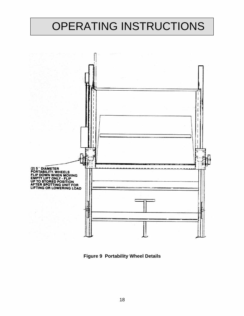
PORTABILITY The portability set is provided on the PDQ as a means of moving the lift from one location to another without a load on the lift. The portability wheels are located on each side of the lift where the lifting cylinder is mounted to the lift platform (See Figure 9). Each lift is supplied with a Dolly-T-Handle that is also necessary for making the unit portable. 1. Raise the lift approximately half way. 2. Flip the portability wheels on the platform over to a vertical hanging position. 3. Lower the lift until the base frame, at the cylinder end, picks itself off of the floor
approximately one inch. 4. The lift can then be moved by pulling or pushing on the “T” handle. To disengage the portability set: 1. Lift the “T” handle to a vertical position and remove it from under the tang. Be
careful, as the handle will have a tendency to pull away as the base is lowered to the floor.
2. Raise the lift approximately half way and rotate the portability wheels on the platform
to their raised and stored position. The lift can then be operated in a normal manner.
NOTE: The lift should not be used for loading or unloading with the wheels in the portability position.
17
OPERATING INSTRUCTIONS
Figure 9 Portability Wheel Details
18
ROUTINE MAINTENANCE
Normally scissors lifts will require very little maintenance. However, a routine maintenance program could prevent costly replacement of parts and/or downtime.
WARNING! To avoid personal injury, NEVER go under the lift platform or perform any maintenance on the lift until the load is removed and the scissors mechanism is securely blocked in the open position. See "Lift Blocking Instructions" section.
MONTHLY INSPECTION 1. Check oil level (see oil recommendations in this section) and add appropriate oil
when necessary. 2. Check for any visible leaks. Correct as necessary. 3. Check any unusual noise when it occurs. Determine the source and correct as
necessary. 4. Check the snap rings at all rollers, if not in place, and/or secure, replace or repair
immediately. 5. Check all rollers for signs of wear. Replace as necessary. 6. Do not grease roller or axles; they have lifetime-lubricated bearings. 7. Check all wiring for looseness or wear. Repair at once. OIL REQUIREMENTS Change oil yearly, or more frequently if it darkens materially or feels gummy or gritty. Use detergent motor oils only. Do not use hydraulic-jack oil, hydraulic fluids, brake fluids, or automatic transmission fluid.
19
ROUTINE MAINTENANCE
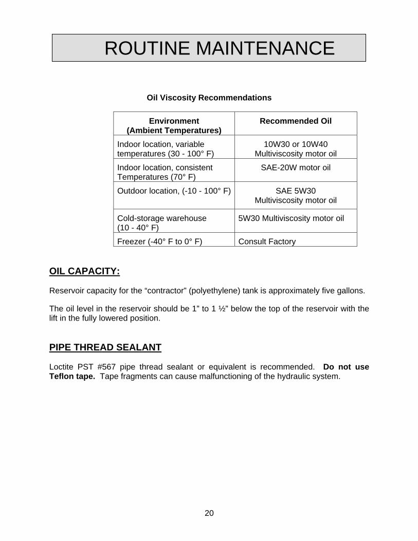
Oil Viscosity Recommendations
Environment (Ambient Temperatures)
Recommended Oil
Indoor location, variable temperatures (30 - 100° F)
10W30 or 10W40 Multiviscosity motor oil
Indoor location, consistent Temperatures (70° F)
SAE-20W motor oil
Outdoor location, (-10 - 100° F)
SAE 5W30 Multiviscosity motor oil
Cold-storage warehouse (10 - 40° F)
5W30 Multiviscosity motor oil
Freezer (-40° F to 0° F) Consult Factory
OIL CAPACITY: Reservoir capacity for the “contractor” (polyethylene) tank is approximately five gallons.
The oil level in the reservoir should be 1” to 1 ½” below the top of the reservoir with the lift in the fully lowered position. PIPE THREAD SEALANT Loctite PST #567 pipe thread sealant or equivalent is recommended. Do not use Teflon tape. Tape fragments can cause malfunctioning of the hydraulic system.
20
GENERAL MAINTENANCE
1. Change oil once a year or when it materially darkens or feels gritty. Also, check oil for the presence of water (oil will turn milky in color.)
2. NEVER TRY TO DISASSEMBLE OR REPAIR A PUMP IN THE FIELD. These
pumps are high-precision devices requiring extreme precision in fit-up. When one is damaged, there is seldom anything that can be repaired in the field. It is also more economical to replace a pump than to refit old parts with new parts.
3. The pin, or roller bushing should be replaced whenever excessive wear is detected.
The rollers are furnished with the pressed-in bushing as a unit part.
DANGER!
To avoid personal injury, NEVER go under the lift platform until the load is removed and the scissors mechanism is securely blocked in the open position.
POWER UNIT
DANGER!
HIGH VOLTAGE!! Disconnect and/or lock out the electrical supply to the power unit prior to any maintenance being performed.
1. The Contractor Power Unit utilizes a “Super-Torque” intermittent duty (one full lift
cycle per four minute period) 5 HP/208, 230, 04 460 Volts/60 hertz/3 phase motor driving a high pressure positive displacement pump assembly with internal relief check and dump valves.
2. Because Autoquip "Super-Torque" motors actually deliver substantially more
horsepower than their nameplate rating, they must always be wired for heavier current-draw than standard motors of the same nameplate rating. However, because of the "Super-Torque" motor’s starting efficiency and superior running characteristics, circuit components do not have to be as large as for standard motors of equal delivered horsepower.
21
GENERAL MAINTENANCE
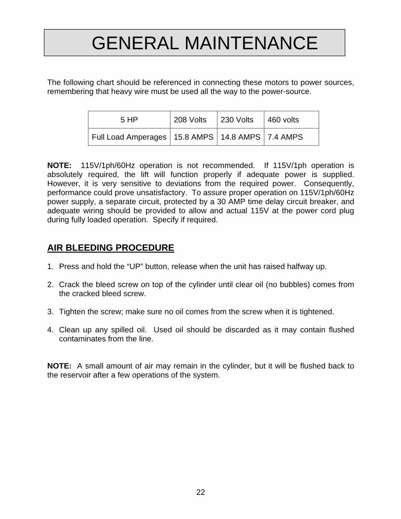
The following chart should be referenced in connecting these motors to power sources, remembering that heavy wire must be used all the way to the power-source.
5 HP 208 Volts 230 Volts 460 volts
Full Load Amperages 15.8 AMPS 14.8 AMPS 7.4 AMPS
NOTE: 115V/1ph/60Hz operation is not recommended. If 115V/1ph operation is absolutely required, the lift will function properly if adequate power is supplied. However, it is very sensitive to deviations from the required power. Consequently, performance could prove unsatisfactory. To assure proper operation on 115V/1ph/60Hz power supply, a separate circuit, protected by a 30 AMP time delay circuit breaker, and adequate wiring should be provided to allow and actual 115V at the power cord plug during fully loaded operation. Specify if required. AIR BLEEDING PROCEDURE 1. Press and hold the “UP” button, release when the unit has raised halfway up. 2. Crack the bleed screw on top of the cylinder until clear oil (no bubbles) comes from
the cracked bleed screw. 3. Tighten the screw; make sure no oil comes from the screw when it is tightened. 4. Clean up any spilled oil. Used oil should be discarded as it may contain flushed
contaminates from the line. NOTE: A small amount of air may remain in the cylinder, but it will be flushed back to the reservoir after a few operations of the system.
22
GENERAL MAINTENANCE
CYLINDER AND/OR SEAL REPLACEMENT Cylinder Removal 1. Lower the lift to the fully lowered position. 2. Continue to hold the “DOWN” button an additional 10 seconds after the lift has
stopped traveling downward to relieve the system pressure. 3. Always shut off the main electrical switch when maintenance is to be performed. 4. Unbolt the two hex head bolts that connect the cylinder to the platform. 5. Disconnect the hydraulic hose from the cylinder.
23
WARNING!
Do not remove the base clevis pin. This will cause the lift to collapse! 6. While protecting the cylinder rod from damage, pry upward and outward on the
cylinder rod. Seal Replacement 1. Lay the ram assembly on its side. 2. To access the seal, push the rod down inside the casing past the seals by threading
a bolt into the end of the rod and simply pushing on the bolt. Take all precautions not to scratch the cylinder rod.
3. Remove the old seal ring and backup ring. Inspect the seal groove for nicks and
scratches that could affect the seal. Remove as necessary. 4. Clean the groove thoroughly and install the new seal and backup. Lubricate the seal
with clean oil or grease. 5. Grasping the bolt in the end of the cylinder rod, pull the rod out of the casing taking
precaution against pinching or tearing the seal ring.
GENERAL MAINTENANCERe-Installing the Cylinder 1. Reinstall the new cylinder in the reverse procedure of the above instructions. 2. Once the cylinder is in place and all hydraulic connections are made tight, proceed
to bleed air out of the system (see “Air Bleeding Procedure” section). 3. Check the oil level. 4. Clean up any debris and/or spilled oil from the area.
24
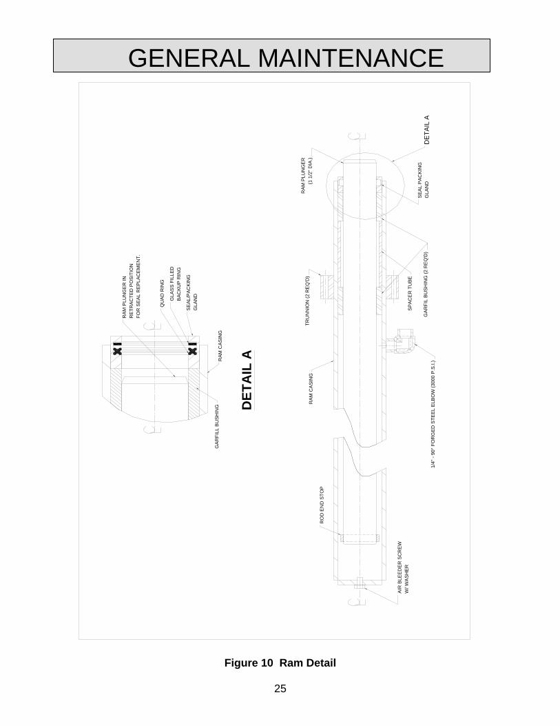
Figure 10 Ram Detail
GENERAL MAINTENANCE
RA
M P
LUN
GER
INR
ETR
ACTE
D P
OS
ITIO
NFO
R S
EAL
RE
PLAC
EMEN
T.
SE
AL/
PAC
KIN
GG
LAN
D
GLA
SS
FILL
EDB
ACKU
P R
ING
QU
AD
RIN
G
RAM
CAS
ING
GAR
FILL
BU
SHIN
G
RA
M C
ASI
NG
RO
D E
ND
STO
P
AIR
BLE
EDE
R S
CR
EWW
/ WA
SHER
TRU
NN
ION
(2 R
EQ
'D)
RAM
PLU
NG
ER(1
1/2
" DIA
.)
DE
TAIL
A
DET
AIL
A
1/4"
- 90
° FO
RG
ED
STE
EL
ELB
OW
(300
0 P
.S.I.
)G
ARFI
L B
US
HIN
G (2
RE
Q'D
)
SPA
CE
R T
UB
E
SEA
L P
ACK
ING
G
LAN
D
25
GENERAL MAINTENANCE VELOCITY FUSE REPLACEMENT
DANGER!
Do not attempt to remove the velocity fuse until the lift is securely supported with the maintenance locking devices and all hydraulic pressure has been removed from the lifting cylinders and hydraulic hoses. Failure to follow these instructions could result in personal injury or death!
Never attempt to take a velocity fuse apart and repair it. These are precision devices that are factory assembled under exacting conditions. Velocity fuses should always be replaced. 1. The arrow on the exterior surface of the velocity fuse shows the direction of the
restriction to the oil flow. The arrow should always point away from the cylinder. 2. Do not use Teflon tape on the threaded connections of a velocity fuse. Tape
fragments can cause malfunctioning of the fuse. 3. Check all fitting connections for hydraulic leaks and tighten as necessary. HOSE ORIENTATION To prevent damage to the cylinder hose and possible failure of lift, it is necessary to establish a correct hose shape and pattern of movement as follows: 1. Raise the lift to its full height and block securely. See “Lift Blocking Instructions”. 2. Install one end of the new hose to the cylinder elbow fitting. 3. Since the hose is fixed at both ends, it is possible to put a twist in the hose that will
allow it to describe the same pattern each time the lift is operated. 4. Lower the lift carefully and check to see that the hose is free and clear of the cylinder
and the leg assembly. If not, twist the hose in the direction necessary to clear it of any obstruction and then lock the swivel fitting securely.
26
GENERAL MAINTENANCE
ROCK SALT It has been discovered that rock salt is being used to melt the ice and snow off of the platforms in the northern region and during the winter months. Rock salt will accelerate the deterioration of any paint. Therefore, Autoquip recommends the use of a synthetic “Ice Melt” product in lieu of rock salt. Warranty on the paint finish will be denied when it is suspected that rock salt has been used. Please contact the Product Support Team at Autoquip at 1-888-811-9876 or 405-282-5200.
27
GENERAL MAINTENANCE
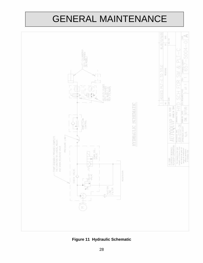
Figure 11 Hydraulic Schematic
28
29
GENERAL MAINTENANCE
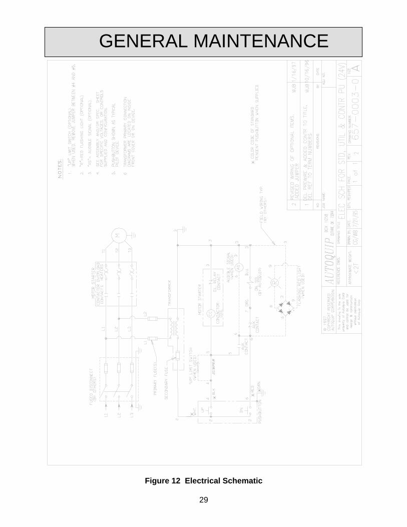
Figure 12 Electrical Schematic
GENERAL MAINTENANCE
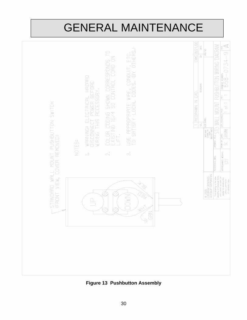
Figure 13 Pushbutton Assembly
30
31
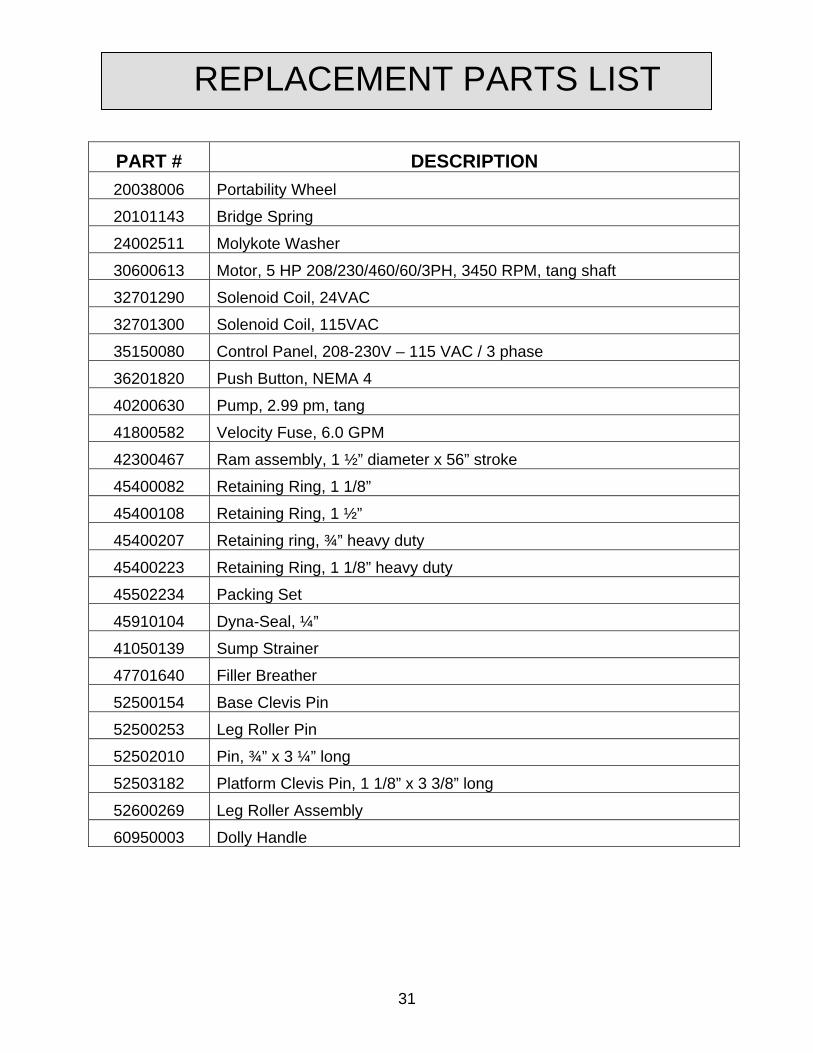
PART # DESCRIPTION 20038006 Portability Wheel
20101143 Bridge Spring
24002511 Molykote Washer
30600613 Motor, 5 HP 208/230/460/60/3PH, 3450 RPM, tang shaft
32701290 Solenoid Coil, 24VAC
32701300 Solenoid Coil, 115VAC
35150080 Control Panel, 208-230V – 115 VAC / 3 phase
36201820 Push Button, NEMA 4
40200630 Pump, 2.99 pm, tang
41800582 Velocity Fuse, 6.0 GPM
42300467 Ram assembly, 1 ½” diameter x 56” stroke
45400082 Retaining Ring, 1 1/8”
45400108 Retaining Ring, 1 ½”
45400207 Retaining ring, ¾” heavy duty
45400223 Retaining Ring, 1 1/8” heavy duty
45502234 Packing Set
45910104 Dyna-Seal, ¼”
41050139 Sump Strainer
47701640 Filler Breather
52500154 Base Clevis Pin
52500253 Leg Roller Pin
52502010 Pin, ¾” x 3 ¼” long
52503182 Platform Clevis Pin, 1 1/8” x 3 3/8” long
52600269 Leg Roller Assembly
60950003 Dolly Handle
REPLACEMENT PARTS LIST
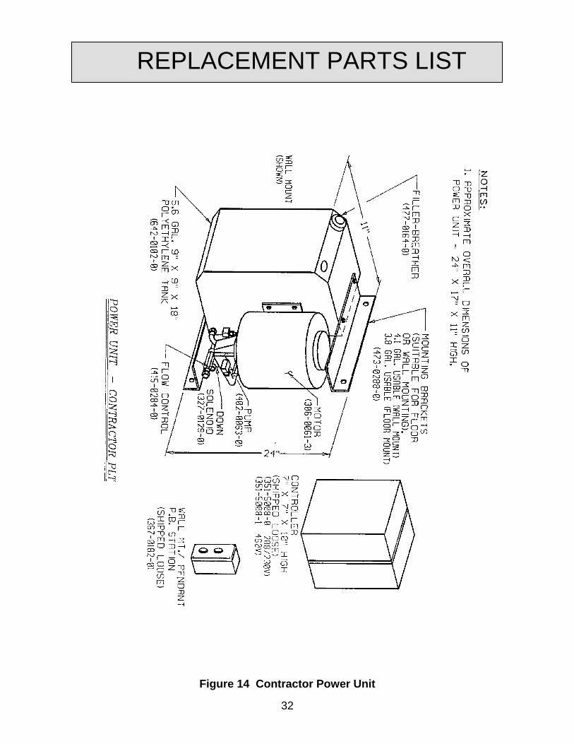
REPLACEMENT PARTS LIST
Figure 14 Contractor Power Unit
32
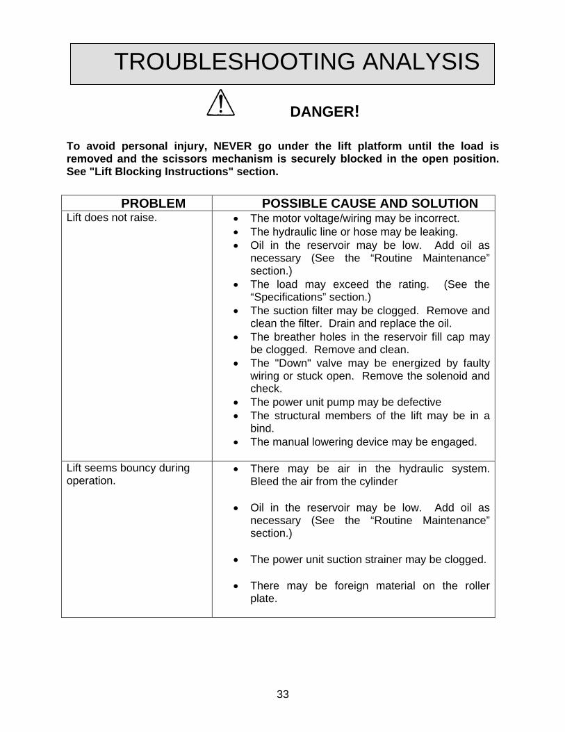
DANGER!
To avoid personal injury, NEVER go under the lift platform until the load is removed and the scissors mechanism is securely blocked in the open position. See "Lift Blocking Instructions" section.
PROBLEM POSSIBLE CAUSE AND SOLUTION Lift does not raise. • The motor voltage/wiring may be incorrect.
• The hydraulic line or hose may be leaking. • Oil in the reservoir may be low. Add oil as
necessary (See the “Routine Maintenance” section.)
• The load may exceed the rating. (See the “Specifications” section.)
• The suction filter may be clogged. Remove and clean the filter. Drain and replace the oil.
• The breather holes in the reservoir fill cap may be clogged. Remove and clean.
• The "Down" valve may be energized by faulty wiring or stuck open. Remove the solenoid and check.
• The power unit pump may be defective • The structural members of the lift may be in a
bind. • The manual lowering device may be engaged.
Lift seems bouncy during operation.
• There may be air in the hydraulic system. Bleed the air from the cylinder
• Oil in the reservoir may be low. Add oil as
necessary (See the “Routine Maintenance” section.)
• The power unit suction strainer may be clogged. • There may be foreign material on the roller
plate.
TROUBLESHOOTING ANALYSIS
33
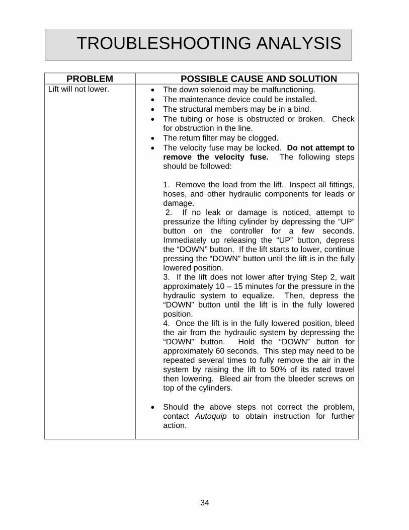
PROBLEM POSSIBLE CAUSE AND SOLUTION Lift will not lower. • The down solenoid may be malfunctioning.
• The maintenance device could be installed. • The structural members may be in a bind. • The tubing or hose is obstructed or broken. Check
for obstruction in the line. • The return filter may be clogged. • The velocity fuse may be locked. Do not attempt to
remove the velocity fuse. The following steps should be followed:
1. Remove the load from the lift. Inspect all fittings, hoses, and other hydraulic components for leads or damage. 2. If no leak or damage is noticed, attempt to pressurize the lifting cylinder by depressing the “UP” button on the controller for a few seconds. Immediately up releasing the “UP” button, depress the “DOWN” button. If the lift starts to lower, continue pressing the “DOWN” button until the lift is in the fully lowered position. 3. If the lift does not lower after trying Step 2, wait approximately 10 – 15 minutes for the pressure in the hydraulic system to equalize. Then, depress the “DOWN” button until the lift is in the fully lowered position. 4. Once the lift is in the fully lowered position, bleed the air from the hydraulic system by depressing the “DOWN” button. Hold the “DOWN” button for approximately 60 seconds. This step may need to be repeated several times to fully remove the air in the system by raising the lift to 50% of its rated travel then lowering. Bleed air from the bleeder screws on top of the cylinders.
• Should the above steps not correct the problem,
contact Autoquip to obtain instruction for further action.
TROUBLESHOOTING ANALYSIS
34
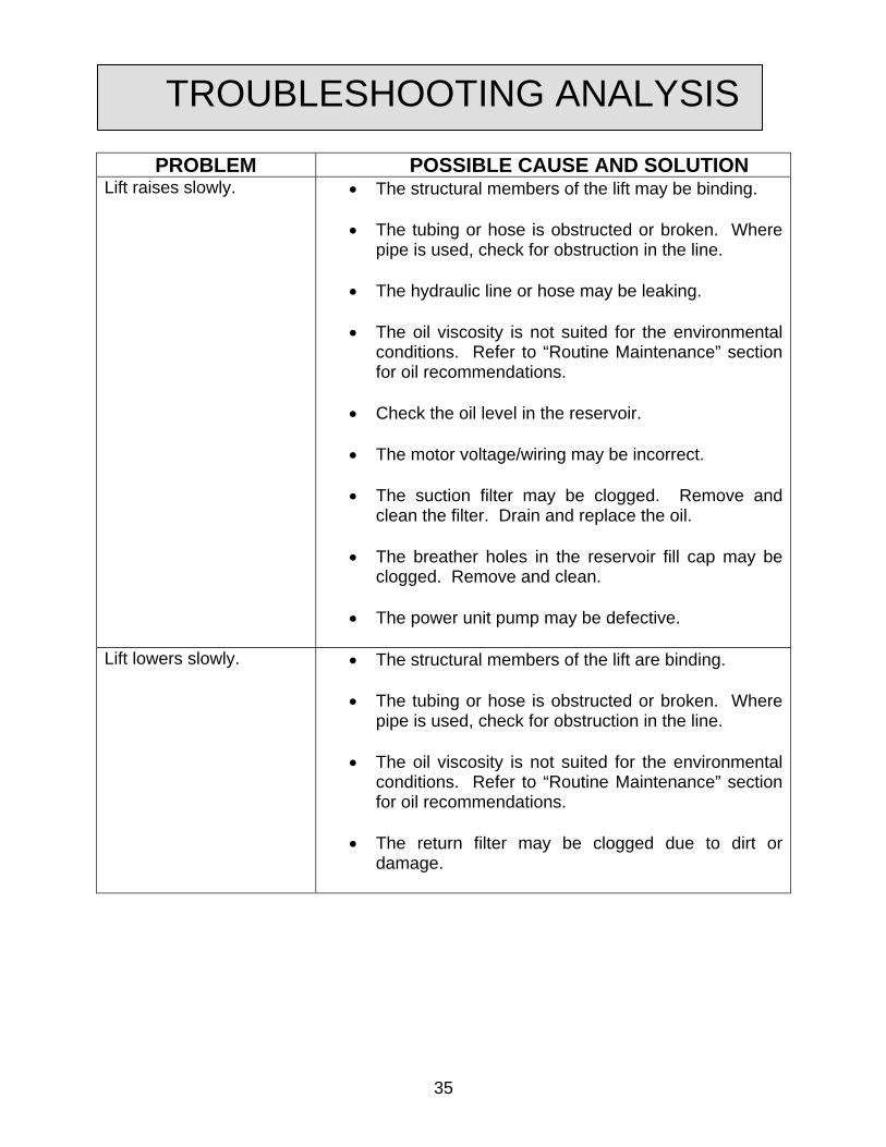
PROBLEM POSSIBLE CAUSE AND SOLUTION Lift raises slowly. • The structural members of the lift may be binding.
• The tubing or hose is obstructed or broken. Where
pipe is used, check for obstruction in the line.
• The hydraulic line or hose may be leaking.
• The oil viscosity is not suited for the environmental conditions. Refer to “Routine Maintenance” section for oil recommendations.
• Check the oil level in the reservoir.
• The motor voltage/wiring may be incorrect.
• The suction filter may be clogged. Remove and
clean the filter. Drain and replace the oil.
• The breather holes in the reservoir fill cap may be clogged. Remove and clean.
• The power unit pump may be defective.
Lift lowers slowly.
• The structural members of the lift are binding. • The tubing or hose is obstructed or broken. Where
pipe is used, check for obstruction in the line.
• The oil viscosity is not suited for the environmental conditions. Refer to “Routine Maintenance” section for oil recommendations.
• The return filter may be clogged due to dirt or
damage.
TROUBLESHOOTING ANALYSIS
35
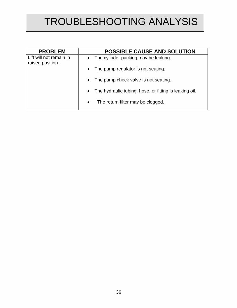
PROBLEM POSSIBLE CAUSE AND SOLUTION Lift will not remain in raised position.
• The cylinder packing may be leaking.
• The pump regulator is not seating.
• The pump check valve is not seating.
• The hydraulic tubing, hose, or fitting is leaking oil. • The return filter may be clogged.
TROUBLESHOOTING ANALYSIS
36
37
LIMITED WARRANTY
The user is solely responsible for using this equipment in a safe manner and observing all of the safety guidelines provided in the Owner’s Manual and on the warning labels provided with the lift. If you are unable to locate either the manual or the warning labels, please contact Autoquip or access www.autoquip.com for replacement downloads or information. Autoquip Corporation expressly warrants that this product will be free from defects in material and workmanship under normal, intended use for a period of Two (2) Years for Labor and all electrical, mechanical, and hydraulic components, parts or devices, and warrants the structure of the lift against breakage or failure for a period of Five (5) years. The warranty period begins from the date of shipment. When making a claim, immediately send your dealer or Autoquip notice of your claim. All claims must be received by Autoquip within the warranty time period. The maximum liability of Autoquip, under this Limited Warranty, is limited to the replacement of the equipment. This warranty shall not apply to any Autoquip lift or parts of Autoquip lift that have been damaged or broken in transit/shipping, or due directly or indirectly to misuse, abuse, vehicle impact, negligence, faulty installation, fire, floods, acts of God, accidents, or that have been used in a manner contrary to the manufacturer’s limitations or recommendations as stated in the manual, or that have been repaired, altered or modified in any manner outside of Autoquip Corp’s manufacturing facility or which have not been expressly authorized by Autoquip. Autoquip Corporation makes no warranty or representation with respect to the compliance of any equipment with state or local safety or product standard codes, and any failure to comply with such codes shall not be considered a defect of material or workmanship under this warranty. Autoquip Corporation shall not be liable for any direct or consequential damages resulting from such noncompliance. Autoquip Corporation’s obligation under this warranty is limited to the replacement or repair of defective components at its factory or another location at Autoquip Corp’s discretion at no cost to the owner. This is owner’s sole remedy. Replacement parts (with exception of electrical components) will be warranted for a period of ninety (90) days. Except as stated herein, Autoquip Corporation will not be liable for any loss, injury, or damage to persons or property, nor for direct, indirect, or consequential damage of any kind, resulting from failure or defective operation of said equipment. All parts used to replace defective material must be genuine Autoquip parts in order to be covered by this Limited Warranty.
.
AUTOQUIP CORP P.O. Box 1058, Guthrie, OK 73044-1058 Telephone: (888) 811-9876 · (405) 282-5200 Fax: (405) 282-8105 www.autoquip.com