Embed Size (px)
Citation preview

PDP-11 MACRO-11Language Reference ManualAA-V027A-TC
March 1983This document describes how to use the MACRO-11 relocatable as-sembler to develop PDP-11 assembly language programs . Although noprior knowledge of MACRO-11 is required, the user should be familiarwith the PDP-11 processor addressing modes and instruction set. Thismanual presents detailed descriptions of MACRO-11's features, includ-ing source and command string control of assembly and listing func-tions, directives for conditional assembly and program sectioning, anduser-defined and system macro libraries . The chapters on operatingprocedures previously were found in two separate manuals (thePDP-11 MACRO-11 Language Reference Manual and the IAS/RSXMACRO-11 Reference Manual) . This manual should be used with asystem-specific user's guide as well as a Linker or a Task Builder man-ual.This manual supersedes previous editions, Order NumbersAA-50758-TC, published 1980, AA-5075A-TC, published 1977, andDEC-11-0IMRA-B-D, published 1976 .
Operating System :
VAX/VMS Version 3RSTS/E Version 8RSX-11 M Version 4RSX-11 M-PLUS Version 2
Software :
MACRO-11 Version 5
To order additional documents from within DIGITAL, contact the Software DistributionCenter, Northboro. Massachusetts 01532 .To order additional documents from outside DIGITAL, refer to the instructions at the backof this document .
digital equipment corporation - maynard, massachusetts

The information in this document is subject to change without notice and should notbe construed as a commitment by Digital Equipment Corporation. Digital EquipmentCorporation assumes no responsibility for any errors that may appear in this docu-ment.The software described in this document is furnished under a license and may be usedor copied only in accordance with the terms of such license.
No responsibility is assumed for the use or reliability of software on equipment that isnot supplied by DIGITAL or its affiliated companies.
© Digital Equipment Corporation 1977, 1980, 1981, 1983 .All Rights Reserved .
Printed in U.S.A .
A postage-paid READER'S COMMENTS form is included on the last page of thisdocument . Your comments will assist us in preparing future documentation.
The following are trademarks of Digital Equipment Corporation:
M19400
First Printing, August 1977Revised, January 1980
Updated, December 1981Revised, March 1983
dB TM980 a 0DEC MASSBUS UNIBUSDECmate PDP VAXDECsystem-10 P/OS VMSDECSYSTEM-20 Professional VTDECUS Rainbow Work ProcessorDECwriter RSTSDIBOL RSX

CONTENTS
PREFACE
PART
I
MACRO-11 :
ASSEMBLY AND FORMATTING
Page
ix
CHAPTER 1
THE MACRO-11 ASSEMBLER
1-1
1 .1
ASSEMBLY PASS 1
1-11 .2
ASSEMBLY PASS 2
1-2
CHAPTER 2
SOURCE PROGRAM FORMAT
2-1
2 .1
PROGRAMMING STANDARDS AND CONVENTIONS
2-12 .2
STATEMENT FORMAT
2-12 .2 .1
Label Field
2-22 .2 .2
Operator Field
2-32 .2 .3
Operand Field
2-42 .2 .4
Comment Field
2-42 .3
FORMAT CONTROL
2-5
PART
II
PROGRAMMING
IN MACRO-11 ASSEMBLY LANGUAGE
CHAPTER 3
SYMBOLS AND EXPRESSIONS
3-1
3 .1
CHARACTER SET
3-13 .1 .1
Separating and Delimiting Characters
3-33 .1 .2
Illegal Characters
3-33 .1 .3
Unary and Binary Operators
3-43 .2
MACRO-11 SYMBOLS
3-63 .2 .1
Permanent Symbols
3-63 .2 .2
User-Defined and Macro Symbols
3-63 .3
DIRECT ASSIGNMENT STATEMENTS
3-83 .4
REGISTER SYMBOLS
3-103 .5
LOCAL SYMBOLS
3-1J.3 .6
CURRENT LOCATION COUNTER
3-1r33 .7
NUMBERS
3-153 .8
TERMS
3-153 .9
EXPRESSIONS
3-16
CHAPTER 4
RELOCATION AND LINKING
4-1
CHAPTER 5
ADDRESSING MODES
5-1
5 .1
REGISTER MODE
5-25 .2
REGISTER DEFERRED MODE
5-25 .3
AUTOINCREMENT MODE
5-35 .4
AUTOINCREMENT DEFERRED MODE
5-45 .5
AUTODECREMENT MODE
5-45 .6
AUTODECREMENT DEFERRED MODE
5-45 .7
INDEX MODE
5-55 .8
INDEX DEFERRED MODE
5-55 .9
IMMEDIATE MODE
5-6

PART
III
CHAPTER
iv
5 .10 ABSOLUTE
MODE
5-65 .11 RELATIVE
MODE
5-75 .12 RELATIVE
DEFERRED MODE
5-85 .13 BRANCH
INSTRUCTION ADDRESSING
5-95 .14 USING
TRAP INSTRUCTIONS
5-9
MACRO-11
DIRECTIVES
6 GENERAL
ASSEMBLER DIRECTIVES
6-1
6 .1 LISTING
CONTROL DIRECTIVES
6-46 .1 .1 LIST
and NLIST Directives
6-96 .1 .2 TITLE
Directive
6-156 .1 .3 SBTTL
Directive
6-156 .1 .4 IDENT
Directive
6-166 .1 .5 PAGE
Directive/Page Ejection
6-176 .1 .6 REM
Directive/Begin Remark Lines
6-186 .2 FUNCTION
DIRECTIVES
6-186 .2 .1 ENABL
and DSABL Directives
6-196 .2 .2 Cross-Reference
Directives
:
CROSS
and
NOCROSS
6-226 .3 DATA
STORAGE DIRECTIVES
6-236 .3 .1 BYTE
Directive
6-236 .3 .2 WORD
Directive
6-246 .3 .3 ASCII
Conversion Characters
6-256 .3 .4 ASCII
Directive
6-256 .3 .5 ASCIZ
Directive
5-286 .3 .6 .RAD50
Directive
6-296 .3 .7 Temporary
Radix-50 Control Operator
6-316 .3 .8 PACKED
Directive
6-316 .4 RADIX
AND NUMERIC CONTROL FACILITIES
6-326 .4 .1 Radix
Control and Unary Control Operators
6-326 .4 .1 .1 RADIX
Directive
6-326 .4 .1 .2 Temporary
Radix Control Operators
6-336 .4 .2 Numeric
Directives and Unary Control
Operators 6-346 .4 .2 .1 Floating-Point
Storage Directives
6-356 .4 .2 .2 Temporary
Numeric Control Operators
:"C
and "F
6-366 .5 LOCATION
COUNTER CONTROL DIRECTIVES
6-376 .5 .1 EVEN
Directive
6-386 .5 .2 ODD
Directive
6-386 .5 .3 BLKB
and BLKW Directives
6-386 .5 .4 LIMIT
Directive
6-396 .5 TERMINATING
DIRECTIVE
:
END DIRECTIVE
6-406 .7 PROGRAM
SECTIONING DIRECTIVES
6-406 .7 .1 PSECT
Directive
6-416 .7 .1 .1 Creating
Program Sections
6-456 .7 .1 .2 Code
or Data Sharing
6-476 .7 .1 .3 Memory
Allocation Considerations
6-476 .7 .2 ASECT
and CSECT Directives
6-486 .7 .3 SAVE
Directive
5-496 .7 .4 RESTORE
Directive
6-496 .8 SYMBOL
CONTROL DIRECTIVES
6-516 .8 .1 GLOBL
Directive
6-516 .8 .2 WEAK
Directive
6-526 .9 CONDITIONAL
ASSEMBLY DIRECTIVES
5-535 .9 .7. Conditional
Assembly Block Directives
S-536 .9 .2 Subconditional
Assembly Block Directives
6-566 .9 .3 Immediate
Conditional Assembly Directive
6-596 .10 FILE
CONTROL DIRECTIVES
6-606 .10 .1 LIBRARY
Directive
6-605 .10 .2 INCLUDE
Directive
6-61
CHAPTER
PART
IV OPERATING PROCEDURES
CHAPTER
8
IAS/RSX-11M/RSX-11M-PLUS
OPERATING PROCEDURES 8-1
8 .1
RSX-11M/RSX-11M-PLUS
OPERATING PROCEDURES
8-18 .1 .1
Initiating
MACRO-11 Under RSX-11M/
RSX-11M-PLUS
8-28 .1 .1 .1
Method
1 - Direct MACRO-11 Call
8-28 .1 .1 .2
Method
2 - Single Assembly
8-28 .1 .1 .3
Method
3 - Install, Run Immediately, and
Remove
On Exit
8-28 .1 .1 .4
Method
4 - Using the Indirect Command
Processor
8-38 .1 .2
Default
File Specifications
8-38 .1 .3
MCR
Command String Format
8-48 .1 .4
DCL
Operating Procedures
8-88 .1 .5
MACRO-11
Command String Examples
8-138 .2
IAS
MACRO-11 OPERATING PROCEDURES
8-148 .2 .1
Initiating
MACRO-11 Under IAS
8-148 .2 .2
IAS
Command String
8-148 .2 .3
IAS
Indirect Command Files
8-168 .2 .4
IAS
Command String Examples
8-168 .3
CROSS-REFERENCE
PROCESSOR (CREF)
8-178 .4
IAS/RSX-11M/RSX-11M-PLUS
FILE SPECIFICATION
8-198 .5
MACRO-11
ERROR MESSAGES UNDER IAS/RSX-11M/
RSX-11M-PLUS
8-20
CHAPTER
9
RSTS/RT-11
OPERATING PROCEDURES
9-1
9 .1
MACRO-11
UNDER RSTS
9-19 .1 .1
RT-11
Through RSTS
9-1
7 MACRO
DIRECTIVES
7-1
7 .1 DEFINING
MACROS
7-17 .1 .1 MACRO
Directive
7-17 .1 .2 ENDM
Directive
7-27 .1 .3 MEXIT
Directive
7-37 .1 .4 MACRO
Definition Formatting
7-47 .2 CALLING
MACROS
7-47 .3 ARGUMENTS
IN MACRO DEFINITIONS AND MACRO
CALLS 7-47 .3 .1 Macro
Nesting
7-67 .3 .2 Special
Characters in Macro Arguments
7-77 .3 .3 Passing
Numeric Arguments as Symbols
7-77 .3 .4 Number
of Arguments in Macro Calls
7-87 .3 .5 Creating
Local Symbols Automatically
7-87 .3 .6 Keyword
Arguments
7-107 .3 .7 Concatenation
of Macro Arguments
7-117 .4 MACRO
ATTRIBUTE DIRECTIVES
:
NARG, NCHR, AND
.NTYPE 7-127 .4 .1 NARG
Directive
7-127 .4 .2 NCHR
Directive
7-137 .4 .3 NTYPE
Directive
7-147 .5 ERROR
AND PRINT DIRECTIVES
7-167 .6 INDEFINITE
REPEAT BLOCK DIRECTIVES
:
IRP AND
.IRPC 7-177 .6 .1 IRP
Directive
7-177 .6 .2 IRPC
Directive
7-187 .7 REPEAT
BLOCK DIRECTIVE
:
REPT, ENDR
7-207 .8 MACRO
LIBRARY DIRECTIVE
:
MCALL
7-207 .9 MACRO
DELETION DIRECTIVE
:
MDELETE
7-21

vi
9 .1 .2 RSX
Through RSTS
9-19 .2 INITTATING
MACRO-11 UNDER RT-11
9-29 .3 RT-11
COMMAND STRING
9-29 .4 FILE
SPECIFICATION OPTIONS
9-49 .5 CROSS-REFERENCE
(CREF) TABLE GENERATION
OPTION 9-59 .5 .1 Obtaining
a Cross-Reference Table
9-59 .5 .2 Handling
Cross-Reference Table Files
9-79 .5 .3 MACRO-11
Error Messages Under RT-11
9-7
APPENDIX A MACRO-11
CHARACTER SETS
A-1
A .1 ASCII
CHARACTER SET
A-1A .2 RADIX-50
CHARACTER SET
A-4
APPENDIX B MACRO-11
ASSEMBLY LANGUAGE AND ASSEMBLER
DIRECTIVES B-1
B .1 SPECIAL
CHARACTERS
B-1B .2 SUMMARY
OF ADDRESS MODE SYNTAX
B-1B .3 ASSEMBLER
DIRECTIVES
B-3
APPENDIX C PERMANENT
SYMBOL TABLE (PST)
C-1
C .
]
. OP
CODES
C-1C .2 MACRO-11
DIRECTIVES
C-6
APPENDIX D ERROR
MESSAGES
D-1
APPENDIX E SAMPLE
CODING STANDARD
E-1
E .1 LINE
FORMAT
E-1E .2 COMMENTS E-1E .3 NAMING
STANDARDS
E-2E .3 .1 Registers E-2E .3 .1 .1 General
Purpose Registers
E-2E .3 .1 .2 Hardware
Registers
E-2E .3 .1 .3 Device
Registers
E-2E .3 .2 Processor
Priority
E-2E .3 .3 Symbols E-3E .3 .3 .1 Symbol
Examples
E-3E .3 .3 .2 Local
Symbols
E-4E .3 .3 .3 Global
Symbols
E-4E .3 .3 .4 Macro
Names
E-4E .3 .3 .5 General
Symbols
E-4E .4 PROGRAM
MODULES
E-5E .4 .1 The
Module Preface
E-5E .4 .2 The
Module
E-5E .4 .3 Module
Example
E-7E .4 .4 Modularity E-8E .4 .4 .1 Calling
Conventions (Inter-Module/
Intea-Module) E-9E .4 .4 .2 Exiting E-9E .4 .4 .3 Success/Failure
Indication
E-9E .4 .4 .4 Module
Checking Routines
E-9E .5 CODE
FORMAT
E-10E .5 .1 Program
Flow
E-10E .5 .2 Common
Exits
E-11E .5 .3 Code
with Interrupts Inhibited
E-12E .5 .4 Code
in System State
E-12E .6 INSTRUCTION
USAGE
E-13E .6 .1 Forbidden
Instructions
E-13E .6 .2 Conditional
Branches
E-14E .7 PROGRAM
SOURCE FILES
E-14

E .8
PDP-11
VERSION NUMBER STANDARD
E-7.4E .8 .1
Displaying
the Version Identifier
E-15E .8 .2
Use
of the Version Number in the Program
E-15
APPENDIX
F
ALLOCATING
VIRTUAL MEMORY
F-1
F .1
GENERAL
HINTS AND SPACE-SAVING GUIDELINES
F-1F .2
MACRO
DEFINITIONS AND EXPANSIONS
F-2F .3
OPERATIONAL
TECHNIQUES
F-3
APPENDIX
G
WRITING
POSITION-INDEPENDENT CODE
G-1
G .1
INTRODUCTION
TO POSITION-INDEPENDENT CODE
G-1G .2
EXAMPLES
G-2
APPENDIX
H
SAMPLE
ASSEMBLY AND CROSS-REFERENCE LISTING
H-1
APPENDIX
I
OBSOLETE
MACRO-11 DIRECTIVES, SYNTAX, AND
COMMAND
LINE OPTIONS
I-1
I .1
OBSOLETE
DIRECTIVES AND SYNTAX
1 .2
OBSOLETE
COMMAND LINE OPTION
I-1
APPENDIX
J
RELEASE
NOTES
J-1
J .1
CHANGES
-- ALL VERSIONS OF MACRO-11
J-1J .2
CHANGES
-- MACRO-11/RSX VERSION ONLY
J-3J .3
CHANGES
-- MACRO-11/RT VERSION ONLY
J-3
FIGURE
3-13-26-16-26-36-46-56-66-77-17-27-37-48-1G-1G-2
TABLE
3-13-23-33-43-55-1
FIGURES
Assembly
Listing Showing Local Symbol Block
3-12Sample
Assembly Results
3-13Example
of Line Printer Assembly Listing
6-5Example
of Teleprinter Assembly Listing
6-7Listing
Produced with Listing Control
Directives 6-13Assembly
Listing Table of Contents
6-16Example
of ENABL and DSABL Directives
6-21Example
of BLKB and BLKW Directives
6-39Example
of SAVE and RESTORE Directives
6-50Example
of NARG Directive
7-13Example
of NCHR Directive
7-14Example
of NTYPE Directive in Macro
Definition 7-15Example
of IRP and IRPC Directives
7-19Sample
CREF Listing
8-19Example
of Position-Dependent Code
G-3Example
of Position-Independent Code
G-3
TABLES
Special
Characters Used in MACRO-11
3-1Legal
Separating Characters
3-3Legal
Argument Delimiters
3-4Legal
Unary Operators
3-4Legal
Binary Operators
3-5Addressing
Modes
5-1

5-2 Symbols
Used in Chapter 5
5-26-1 Directives
in Chapter 6
6-16-2 Symbolic
Arguments of Listing Control
Directives 6-106-3 Symbolic
Arguments of Function Control
Directives 6-196-4 Symbolic
Arguments of PSECT Directive
6-416-5 Program
Section Default Values
6-486-6 Legal
Condition Tests for Conditional
Assembly
Directives
6-546-7 Subconditional
Assembly Block Directives
6-578-1 File
Specification Default Values
8-48-2 MACRO-11
File Specification Switches
8-68-3 DCL
Command Qualifiers
8-88-4 DCL
Parameter Qualifiers
8-139-1 Default
File Specification Values
9-39-2 File
Specification Options
9-49-3 /C
Option Arguments
9-6I-1 Old
and New Directives and Syntax
I-1

0 .1
MANUAL OBJECTIVES AND READER ASSUMPTIONS
This
manual is intended to enable users to develop programs coded in
the
MACRO-11 assembly language
.
No
prior knowledge of the MACRO-11 Relocatable Assembler is assumed,
but
the reader should be familiar with the PDP-11 processors and
related
terminology, as presented in the PDP-11 Processor Handbooks
.The
reader is also encouraged to become familiar with the linking
process,
as presented in the applicable system manual (see Section
0 .3),
because linking is necessary for the development of executable
programs .
If
a terminal is available to the reader, he/she is advised to try
some
of the examples in the manual or to write a few simple programs
that
illustrate the concepts covered
.
Even experienced programmers
find
that working with a simple program helps them to understand a
confusing
feature of a new language
.
The
examples in this manual were done on an RT-11 system
.
MACRO-11may
also be used on IAS/RSX-11M, RSX-11M-PLUS and RSTS systems (see
Part
IV for information about operating procedures)
.
It
can be assumed that all references to RSX-11M also apply to
RSX-11M-PLUS
with the exception of those in chapter 8, which deals
with
each system individually
.
0 .2
STRUCTURE OF THE DOCUMENT
PREFACE
This
manual has four parts and eight appendices
.
Part
I introduces MACRO-11
.
Chapter
1 lists the key features of MACRO-11
.
Chapter
2 identifies the advantages of following programming
standards
and conventions and describes the format used in coding
MACRO-11
source programs
.
Part
II presents general information essential to programming with the
MACRO-11
assembly language
.
Chapter
3 lists the character set and describes the symbols,
terms,
and expressions that form the elements of MACRO-11
instructions .

Chapter
4 describes the output of MACRO-11 and presents concepts
essential
to the proper relocation and linking of object modules
.
Chapter
5 describes how data stored in memory can be accessed and
manipulated
using the addressing modes recognized by the PDP-11
hardware .
Part
III describes the MACRO-11 directives that control the processing
of
source statements during assembly
.
Chapter
6 discusses directives used for generalized MACRO-11
functions .
Chapter
7 discusses directives used in the definition and
expansion
of macros
.
Part
IV presents the operating procedures for assembling MACRO-11
programs .
Chapter
8 covers the IAS, RSX-11M, and RSX-11M-PLUS systems
.
Chapter
9 covers the RSTS/RT-11 systems
.
Appendix
A lists the ASCII and Radix-50 character sets used in
MACRO-11
programs
.
Appendix
B lists the special characters recognized by MACRO-11,
summarizes
the syntax of the various addressing modes used in PDP-11
processors,
and briefly describes the MACRO-11 directives in
alphabetical
order
.
Appendix
C lists alphabetically the permanent symbols that have been
defined
for use with MACRO-11
.
Appendix
D lists alphabetically the error codes produced by MACRO-11
to
identify various types of errors detected during the assembly
process .
Appendix
E contains a coding standard that is recommended practice in
preparing
MACRO-11 programs
.
Appendix
F discusses several methods of conserving dynamic memory
space
for users of small systems who may experience difficulty in
assembling
MACRO-11 programs
.
Appendix
G is a discussion of position-independent code (PIC)
.
Appendix
H contains an assembly and cross-reference listing
.
Appendix
I contains obsolete MACRO-11 directives, syntax, and command
line
options
.
Appendix
J describes the differences from the last release of
MACRO-11 .

0 .3
ASSOCIATED DOCUMENTS
For
descriptions of documents associated with this manual, refer to
the
applicable documentation directory listed below
:
IAS
Documentation Directory
RSX-11M-PLUS
Information Directory and Index
RSX-11M/RSX-11S
Information Directory and Index
Guide
to RT-11 Documentation
RSTS/E
Documentation Directory
0 .4
DOCUMENT CONVENTIONS
The
color red is used in command string examples to indicate user
type-in .
The
symbols defined below are used throughout this manual
.
Symbol
Definition
(]
Brackets
indicate that the enclosed argument is
optional .
Ellipsis
indicates optional continuation of an argument
list
in the form of the last specified argument
.
UPPER-CASE
Upper-case
characters indicate elements of the language
CHARACTERS
that
must be used exactly as shown
.
lower-case
Lower-case
characters indicate elements of the language
characters
that
are supplied by the programmer
.
(n)
In
some instances the symbol (n) is used following a
number
to indicate the radix
.
For
example, 100(8)
indicates
that 100 is an octal value, while 100(10)
indicates
a decimal value
.


CHAPTER
1
THE
MACRO-11 ASSEMBLER
MACRO-11
provides the following features
:
Source
and command string control of assembly functions
2 .
Device and filename specifications for input and output files
3 .
Error listing on command output device
4 .
Alphabetized, formatted symbol table listing
;
optional
cross-reference
listing of symbols
5 .
Relocatable object modules
6 .
Global symbols for linking object modules
7 .
Conditional assembly directives
8 .
Program sectioning directives
9 .
User-defined macros and macro libraries
10 .
Comprehensive system macro library
11 .
Extensive source and command string control of listing
functions .
MACRO-11
assembles one or more ASCII source files containing MACRO-11
statements
into a single relocatable binary object file
.
The output
of
MACRO-11 consists of a binary object file and a file containing the
table
of contents, the assembly listing, and the symbol table
.
An
optional
cross-reference listing of symbols and macros is available
.A
sample assembly listing is provided in Appendix H
.
1 .1
ASSEMBLY PASS 1
During
pass 1, MACRO-11 locates and reads all required macros from
libraries,
builds symbol tables and program section tables for the
program,
and performs a rudimentary assembly of each source statement
.
In
the first step of assembly pass 1, MACRO-
.11
initializes all the
impure
data areas (areas containing both code and data) that will be
used
internally for the assembly process
.
These areas include all
dynamic
storage and buffer areas used as file storage regions
.
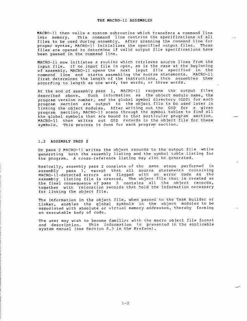
At the end of assembly pass 1, MACRO-1J. reopens the output filesdescribed above . Such information as the object module name, theprogram version number, and the global symbol directory (GSD) for eachprogram section are output to the object file to be used later inlinking the object modules . After writing out the GSD for a givenprogram section, MACRO-11 scans through the symbol tables to find allthe global symbols that are bound to that particular program section .MACRO-11 then writes out GSD records to the object file for thesesymbols . This process is done for each program section .
1 .2 ASSEMBLY PASS 2
THE MACRO-11 ASSEMBLERMACRO-11 then calls a system subroutine which transfers a command lineinto memory . This command line contains the specifications of allfiles to be used during assembly . After scanning the command line forproper syntax, MACRO-11 initializes the specified output files . Thesefiles are opened to determine if valid output file specifications havebeen passed in the command line .MACRO-11 now initiates a routine which retrieves source lines from theinput file . If no input file is open, as is the case at the beginningof assembly, MACRO-11 opens the next input file specified in thecommand line and starts assembling the source statements . MACRO-11first determines the length of the instructions, then assembles themaccording to length as one word, two words, or three words .
On pass 2 MACRO-11 writes the object records to the output file whilegenerating both the assembly listing and the symbol table listing forthe program . A cross-reference listing may also be generated .Basically, assembly pass 2 consists of the same steps performed inassembly pass 1, except that all source statements containingMACRO-11-detected errors are flagged with an error code as theassembly listing file is created . The object file that is created asthe final consequence of pass 2. contains all the object records,together with relocation records that hold the information necessaryfor linking the object file .The information in the object file, when passed to the Task Builder orLinker, enables the global symbols in the object modules to beassociated with absolute or virtual memory addresses, thereby formingan executable body of code .The user may wish to become familiar with the macro object file formatand description . This information is presented in the applicablesystem manual (see Section 0 .3 in the Preface) .

2 .1
PROGRAMMING STANDARDS AND CONVENTIONS
Programming
standards and conventions allow code written by a person
(or
group) to be easily understood by other people
.
These standards
also
make the program easier to
:
PlanComprehendTestModifyConvert
The
actual standard used must meet local user requirements
.
A sample
coding
standard is provided in Appendix E
.
Used by DIGITAL and its
users,
this coding example simplifies both communications and the
continuing
task of software maintenance and improvement
.
2 .2
STATEMENT FORMAT
A
source program is composed of assembly-language statements
.
Eachstatement
must be completed on one line
.
Although a line may contain
132
characters (a longer line causes an error (L) in the assembly
listing),
a line of 80 characters is recommended because of
constraints
imposed by listing format and terminal line size
.
Blanklines,
although legal, have no significance in the source program
.
A
MACRO-11 statement may have as many asare identified by their order withinseparating characters between the fields
.
MACRO-11 statement is
:
[Label :]
Operator Operand
The
label and comment fields
fields
are interdependent
;present
in a source statement,
the
context of the other
.
CHAPTER
2
SOURCE
PROGRAM FORMAT
A
statement may contain an operator and no
not
true
.
A statement containing
illegal
and is interpreted by MACRO-11
.WORD
directive (see Section 5
.3 .2) .
MACRO-11
interprets and processes source
one .
Each statement causes
assembly
process or to generate one or more
data
words
.
are
optiona
in
other words, when both fields are
each
field is evaluated by MACRO-11 in
operand,
but the reverse is
an
operand with no operator is
during
assembly as an implicit
program
statements one by
MACRO-11
either to perform a specified
binary
instructions or
four
fields
. These fieldsthe
statement
and/or by
the
The
general
format of
a
Comment(s)]
.
The operator
and operand

2 .2 .1
Label Field
A
label is a user-defined symbol which is assigned the value of the
current
location counter and entered into the user-defined symbol
table .
The current location counter is used by MACRO-11 to assign
memory
addresses to the source program statements as they are
encountered
during the assembly process
.
Thus, a label is a means of
symbolically
referring to a specific statement
.
When
a program section is absolute, the value of the current location
counter
is absolute
;
its value references an absolute virtual memory
address
(such as location 100)
.
Similarly, when a program section is
relocatable,
the value of the current location counter is relocatable
;a
relocation bias calculated at link time is added to the apparent
value
of the current location counter to establish its effective
absolute
virtual address at execution time
.
(For a discussion of
program
sections and their attributes, see Section 6
.7 .)
If
present, a label must be the first field in a source statement
must
be terminated by a colon (
:) .
For example, if the value of
current
location counter is absolute 100(8), the statement
:
ABCD :
MOV A,B
assigns
the value 100(8) to the label ABCD
.value
were relocatable, the final value
where
K represents the relocation bias of
calculated
by the Task Builder or Linker at
More
than one label may appear within a single label field
.
Eachlabel
so specified is assigned the same address value
.
For example,
if
the value of the current location counter is 100(8), the multiple
labels
in the following statement are each assigned the value 100(8)
:
ABC :
$DD
:
A7
.7 :
MOV A,B
Multiple
labels may also appear on successive lines
.statements
ABC :$DD :A7 .7 :
MOV
A,B
SOURCE
PROGRAM FORMAT
likewise
cause the same value to be assigned to
This
second method of assigning multiple labels
positioning
the fields consistently within the
the
program easier to read (see Section 2
.3) .
A
double colon (
: :)
defines the label
example,
the statement
ABCD : :
MOV A,B
andthe
If
the location counter
of
ABCD would be 100(8)+K,
the
program section, as
link
time
.
For
example, the
all
three
labels .i s
preferred because
source
program makes
as
a global symbol
.
For
establishes
the label ABCD as a global symbol
.
The
distinguishing
attribute
of a global symbol is that it can be referenced from within
an
object module other than the module in which the symbol is defined
(see
Section 6
.8)
or by independently assembled object modules
.References
to this label in other modules are resolved when the
modules
are linked as a composite executable image
.

The
legal characters for defining labels are
:
A
through Z
0
through 9
(Period)S
(Dollar Sign)
2 .2 .2
Operator Field
SOURCE
PROGRAM FORMAT
NOTE
By
convention, the dollar sign ($) and
period
(
.)
are reserved for use in
defining
DIGITAL system software
symbols .
Therefore these characters
should
not be used in defining labels in
MACRO-11
source programs
.
A
label may be any length
;
however, only the first six characters are
significant
and, therefore, must be unique among all the labels in the
source
program
.
An error code (M) is generated in the assembly
listing
if the first six characters in two or more labels are the
same .
A
symbol used as a label must not be redefined within the source
program .
If the symbol is redefined, a label with a multiple
definition
results, causing MACRO-11 to generate an error code (M) in
the
assembly listing
.
Furthermore,
any statement in the source
program
which references a multi-defined label generates an error code
(D)
in the assembly listing
.
The
operator field specifies the action to be performed
.
It
may
consist
of an instruction mnemonic (op code), an assembler directive,
or
a macro call
.
Chapters 6 and 7 describe these three types of
operators .
When
the operator is an instruction mnemonic, a machine instruction is
generated
and MACRO-11 evaluates the addresses of the operands which
follow .
When the operator is a directive MACRO-11 performs certain
control
actions or processing operations during the assembly of the
source
program
.
When the operator is a macro call, MACRO-11 inserts
the
code generated by the macro expansion
.
Leading
and trailing spaces or tabs in the operator field have no
significance ;
such characters serve only to separate the operator
field
from the preceding and following fields
.
An
operator is terminated by a space, tab, or any non-RAD50
character*,
as in the following examples
:
MOV
A,B
;The
space terminates the operator MOV
.
MOV
A,B
;The
tab terminates the operator MOV
.
MOV@A,B
;The
@ character terminates the operator MOV
.
*
Appendix A
.2
contains a table of Radix-50 characters
.
2-3
2 .2 .3
Operand Field
MOV
RO,A+2(R1)
.MACRO
ALPHA SYM1,SYM2
2 .2 .4
Comment Field
SOURCE
PROGRAM FORMAT
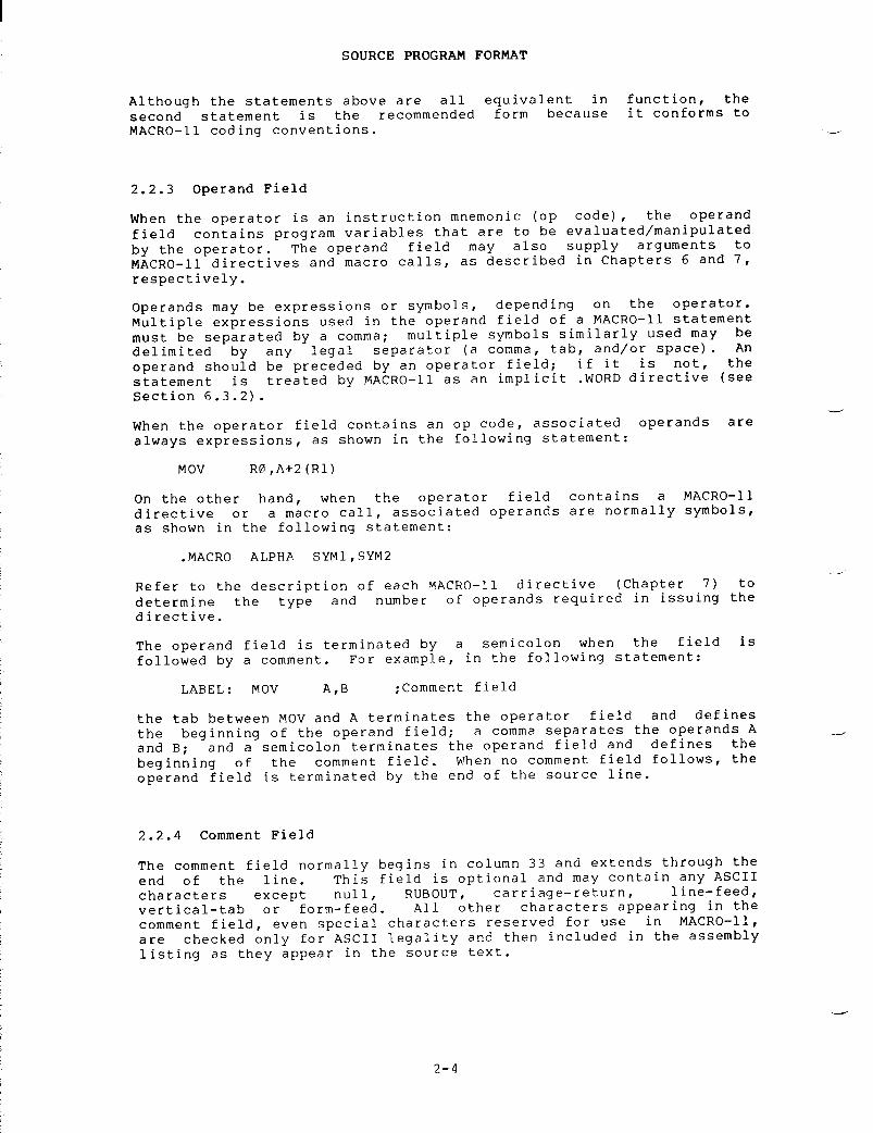
Although
the statements above are all equivalent in function, the
second
statement is the recommended form because it conforms to
MACRO-11
coding conventions
.
When
the operator is an instruction mnemonic (op code), the operand
field
contains program variables that are to be evaluated/manipulated
by
the operator
.
The operand field may also supply arguments to
MACRO-11
directives and macro calls, as described in Chapters 6 and 7,
respectively .
Operands
may be expressions or symbols, depending on the operator
.Multiple
expressions used in the operand field of a MACRO-11 statement
must
be separated by a comma
;
multiple symbols similarly used may be
delimited
by any legal separator (a comma, tab, and/or space)
.
An
operand
should be preceded by an operator field
;
if it is not, the
statement
is treated by MACRO-11 as an implicit WORD directive (see
Section
6
.3 .2) .
When
the operator field contains an op code, associated operands are
always
expressions, as shown in the following statement
:
On
the other hand, when the operator field contains a MACRO-11
directive
or a macro call, associated operands are normally symbols,
as
shown in the following statement
:
Refer
to the description of each MACRO-11 directive (Chapter 7) to
determine
the type and number of operands required in issuing the
directive .
The
operand field is terminated by a semicolon when the field is
followed
by a comment
.
For example, in the following statement
:
LABEL :
MOV
A,B
;Comment
field
the
tab between MOV and A terminates the operator field and defines
the
beginning of the operand field
;
a comma separates the operands A
and
B
;
and a semicolon terminates the operand field and defines the
beginning
of the comment field
.
When no comment field follows, the
operand
field is terminated by the end of the source line
.
The
comment field normally begins in column 33 and extends through the
end
of the line
.
This field is optional and may contain any ASCII
characters
except null, RUBOUT, carriage-return, line-feed,
vertical-tab
or form-feed
.
All
other characters appearing in the
comment
field, even special characters reserved for use in MACRO-11,
are
checked only for ASCII legality and then included in the assembly
listing
as they appear in the source text
.

All
comment fields must begin with a semicolon (
;) .
When
lengthy
comments
extend beyond the end of the source line (column 80), the
comment
may be resumed in a following line
.
Such a line must contain
a
leading semicolon, and it is suggested that the body of the comment
be
continued in the same columnar position in which the comment began
.A
comment line can also be included as an entirely separate line
within
the code body
.
Comments
do not affect assembly processing or program execution
.However,
comments are necessary in source listings for later analysis,
debugging,
or documentation purposes
.
2 .3
FORMAT CONTROL
Horizontal
formatting of the source program is controlled by the space
and
tab characters
.
These characters have no effect on the assembly
process
unless they are embedded within a symbol, number, or ASCII
text
string, or unless they are used as the operator field terminator
.Thus,
the space and tab characters can be used to provide an orderly
and
readable source program
.
DIGITAL's
standard source line format is shown below
:
Label
- begins in column 1
Operator
- begins in column 9
Operands
- begin in column 17
SOURCE
PROGRAM FORMAT
Comments
- begin in column 33
.
These
formatting conventions are not mandatory
;
free-field coding is
permissible .
However, note the increase readability after formatting
in
the example below
:
REGTST :BIT#MASK,VALUE ;COMPARES
BITS IN OPERANDS
.
1
9 17
33
(columns)
REGTST :
BIT
#MASK,VALUE
;Compares
bits in operands
.
Page
formatting and assembly listing considerations are discussed in
Chapter
5 in the context of MACRO-11 directives that may be specified
to
accomplish desired formatting operations
.
Appendix E contains a
sample
coding standard
.


This
chapter describes the components of MACRO-11 instructions
:
thecharacter
set, the conventions observed in constructing symbols, and
the
use of numbers, operators, terms and expressions
.
3 .1
CHARACTER SET
The
following characters are legal in MACRO-11 source programs
:
1 .
The letters A through Z
.
Both upper- and lower-case letters
are
acceptable, although, upon input, lower-case letters are
converted
to upper-case (see Section 6
.2 .1,
ENABL LC)
.
2 .
The digits 0 through 9
.
CHAPTER
3
SYMBOLS
AND EXPRESSIONS
3 .
The characters
(period)
and $ (dollar sign)
.
Thesecharacters
are reserved for use as Digital Equipment
Corporation
system program symbols
.
4 .
The special characters listed in Table 3-1
.
Table
3-1
Special
Characters Used in MACRO-11
Character
Designation
Function
Colon
Label
terminator
.
Double
colon
Label
terminator
;
defines the
label
as a global label
.
Equal
sign
Direct
assignment operator and
macro
keyword indicator
.
Double
equal
Direct
assignment operator
;sign
defines
the symbol as a global
symbol .
Equal
sign colon
Direct
assignment
operator ;macro
keyword indicator
;causes
error (M) in listing if
an
attempt is made to change
the
value of the symbol
.
(continued
on next page)

Character
Designation
Function
SYMBOLS
AND EXPRESSIONS
Table
3-1 (Copt
.)Special
Characters Used in MACRO-11
(continued
on next page)
Double
equal
sign
colon
Direct
assignment operator
;defines
the symbol as a global
symbol ;
causes error (M) in
listing
if an attempt is made
to
change the value of the
symbol .
Percent
sign
Register
term indicator
.
Tab Item
or field terminator
.
Space Item
or field terminator
.
Number
sign
Immediate
expression
indicator .
At
sign
Deferred
addressing indicator
.
( Left
parenthesis
Initial
register indicator
.
Right
parenthesis
Terminal
register indicator
.
Period Current
location counter
.
Comma operand
field separator
.
Semicolon Comment
field indicator
.
< Left
angle
Initial
argument or expression
bracket indicator .
> Right
angle
Terminal
argument or
bracket expression
indicator
.
+ Plus
sign
Arithmetic
addition operator
or
autoincrement indicator
.
Minus
sign
Arithmetic
subtraction
operator
or autodecrement
indicator .
* Asterisk Arithmetic
multiplication
operator .
/ Slash Arithmetic
division operator
.
& Ampersand Logical
AND operator
.
! Exclamation
point
Logical
inclusive OR operator
.
" Double
quote
Double
ASCII character
indicator .

Character
Designation
\
Backslash
Character
Definition
3 .1 .2
Illegal Characters
SYMBOLS
AND EXPRESSIONS
Table
3-1 (Coat
.)Special
Characters Used in MACRO-11
Single
quote
Up
arrow or
circumflex
3 .1 .1
Separating and Delimiting Characters
Space
One
or more spaces
and/or
tabs
Comma
A
character is illegal for one of
Table
3-2
Legal
Separating Characters
Function
Single
ASCII character
indicator ;
or concatenation
indicator .
Universal
unary operator or
argument
indicator
.
Macro
call numeric argument
indicator .
Legal
separating characters and legal argument delimiters
in
Tables 3-2 and 3-3 respectively
.are
defined
A
space is a legal separator
between
instruction fields and
between
symbolic arguments
within
the operand field
.Spaces
within expressions are
ignored
(see Section 3
.9) .
A
comma is a legal separator
between
symbolic arguments
within
the operand field
.Multiple
expressions used in
the
operand field must be
separated
by a comma
.
two
reasons
:
Usage
1 .
If a character is not an element of the recognized
character
set, it is replaced in the listing by a
mark,
and an error code (I) is printed in the
listing .
The
exception to this is an embedded null
when
detected, terminates the scan of the current line
.
2 .
If a legal MACRO-11 character is used in a
with
illegal or questionable syntax, an
printed
in the assembly listing
.
MACRO-11questionassembly
which,
source
statement
error
code (Q) is

Character
Definition
< . . .>
Paired
angle
brackets
"x . . .x
Up-arrow
(unary
operator)
con-
struction,
where
the
up-arrow is
followed
by an
argument
that is
bracketed
by any
paired
printing
characters
(x)
.
3 .1 .3
Unary and Binary Operators
SYMBOLS
AND EXPRESSIONS
Table
3-3
Legal
Argument Delimiters
Legal
MACRO-11 unary operators are described in Table
operators
are used in connection with single terms
operands)
to indicate an action to be performed on that
assembly .
Because a term preceded by a unary operator
to
contain that operator, a term so specified can be used
an
element of an expression
.
Table
3-4
Legal
Unary Operators
UnaryOperator
Usage
Paired
angle brackets may be
used
anywhere in a program to
enclose
an expression for
treatment
as a single term
.Paired
angle brackets are also
used
to enclose a macro
argument,
particularly when
that
argument contains
separating
characters (see
Section
7
.3) .
This
construction is
equivalent
in function to the
paired
angle brackets
described
above and is
generally
used only where the
argument
itself contains angle
brackets .
3-4 .
Unary
(arguments
or
term
during
is
considered
alone
or as
(continued
on next page)
Explanation Example Effect
Plus
sign
+A Produces
the positive
value
of A
.
Minus
sign
-A Produces
the negative
(2
's complement)
value
of A
.

SYMBOLS
AND EXPRESSIONS
Table
3-4 (Cont
.)Legal
Unary Operators
UnaryOperator
-"D50
(Equivalent
to -<"D50>)
"C"012
(Equivalent to "C<"012>)
"RABC
Evaluates
ABC in
Radix-50
form
.
Unary
operators can be used adjacent to each other or in constructions
involving
multiple terms, as shown below
:
Legal
MACRO-11 binary operators are described in Table 3-5
.
Incontrast
to unary operators, binary operators specify actions to be
performed
on multiple items or terms within an expression
.
Table
3-5
Legal
Binary Operators
BinaryOperator Explanation Example
+ Addition A+B
- Subtraction A-B
* Multiplication A*B (signed
16-bit
product
returned)
/ Division A/B (signed
16-bit
quotient
returned)
& Logical
AND
A&B
! Logical
inclusive OR
A!B
Explanation Example Effect
Up-arrow,
universal
"C24 Produces
the 1's
unary
operator
. complement
value of
(This
usage is
24(8) "described
in
detail
in
"D127 Interprets
127 as a
Section
6
.4 .) decimal
number
."F3 .0 Interprets
3
.0
as a
1-word,floating-pointnumber .
"034 Interprets
34 as an
octal
number
."B11000111 Interprets
11000111
as
a binary number
.

All
binary operators have equal priority
.
Terms
enclosed by angle
brackets
are evaluated first, and remaining operations are performed
from
left to right, as shown in the examples below
:
.WORD
1+2*3
;Equals
11(8)
..WORD
1+<2*3>
;Equals
7(8)
.
3 .2
MACRO-11 SYMBOLS
MACRO-11
maintains a symbol table for each of the three symbol types
that
may be defined in a MACRO-11 source program
:
the Permanent
Symbol
Table (PST), the User Symbol Table (UST), and the Macro Symbol
Table
(MST)
.
The PST contains all the permanent symbols defined
within
(and thus automatically recognized by) MACRO-11 and is part of
the
MACRO-11 image
.
The UST (for user-defined symbols) and MST (for
macro
symbols) are constructed as the source program is assembled
.
3 .2 .1
Permanent Symbols
SYMBOLS
AND EXPRESSIONS
Permanent
symbols consist of the instruction mnemonics (see Appendix
C)
and MACRO-11 directives (see Chapters 6 and 7 and Appendix B)
.These
symbols are a permanent part of the MACRO-11 image and need not
be
defined before being used in the operator field of a MACRO-11
source
statement (see Section 2
.2 .2) .
3 .2 .2
User-Defined and Macro Symbols
User-defined
symbols are those symbols that are equated to a specific
value
through a direct assignment statement (see Section 3
.3),
appear
as
labels (see Section 2
.2 .1),
or act as dummy arguments (see Section
7 .1 .1) .
These symbols are added to the User Symbol Table as they are
encountered
during assembly
.
Macro
symbols are those symbols used as macro names (see Section 7
.1) .They
are added to the Macro Symbol Table as they are encountered
during
assembly
.
The
following rules govern the creation of user-defined and macro
symbols :
1 .
Symbols can be composed of alphanumeric characters, dollar
signs
($), and periods (
.)
only (see Note below)
.
2 .
The first character of a symbol must not be a number (except
in
the case of local symbols
;
see Section 3
.5) .
3 .
The first six characters of a symbol must be unique
.
Asymbol
can be written with more than six legal characters,
but
the seventh and subsequent characters are checked only
for
ASCII legality and are not otherwise evaluated or
recognized
by MACRO-11
.
4 .
Spaces, tabs, and illegal characters must not be embedded
within
a symbol
.
The legal MACRO-11 character set is defined
in
Section 3
.1 .

The
dollar sign ($) and period (
.)characters
are reserved for use in
defining
Digital Equipment Corporation
system
software symbols
.
For example,
READ$
is a file-processing system macro
.The
user is cautioned not to employ
these
characters in constructing
user-defined
symbols or macro symbols in
order
to avoid possible conflicts with
existing
or future Digital Equipment
Corporation
system software symbols
.
The
value of a symbol depends upon its use in the program
.
A
symbol
in
the operator field may be any one of the three symbol types
described
above
;
permanent, user-defined, or macro
.
To determine the
value
of an operator-field symbol, MACRO-11 searches the symbol tables
in
the following order
:
1 .
Macro Symbol Table
2 .
Permanent Symbol Table
3 .
User-Defined Symbol Table
This
search order allows permanent symbols to be used as macro
symbols .
But the user must keep in mind the sequence in which the
search
for symbols is performed in order to avoid incorrect
interpretation
of the symbol's use
.
When
a symbol appears in the operand field, the search order is
:
1 .
User-Defined Symbol Table
2 .
Permanent Symbol Table
SYMBOLS
AND EXPRESSIONS
NOTE
Depending
on their use in the source program, user-defined symbols
have
either a local (internal) attribute or a global (external)
attribute .
Normally,
MACRO-11 treats all user-defined symbols as local, that is,
their
definition is limited to the module in which they appear
.However,
symbols can be explicitly declared to be global symbols
through
one of three methods
:
1 .
Use of the GLOBL directive (see Section 6
.8 .1) .
2 .
Use of the double colon (
: :)
in defining a label (see Section
2 .2 .1) .
3 .
Use of the double equal sign (==) or double equal colon sign
(== :)
in a direct assignment statement (see Section 3
.3) .
All
symbols within a module that remain undefined at the end of
assembly
are treated as default global references
.

SYMBOLS
AND EXPRESSIONS
NOTE
Undefined
symbols at the end of assembly
are
assigned a value of 0 and placed
into
the user-defined symbol table as
undefined
default global references
.
If
the
DSABL GBL directive is in effect,
however,
(see Section 6
.2 .1)
the
statement
containing the undefined
symbol
is flagged with an error code (U)
in
the assembly listing
.
Global
symbols provide linkages between independently-assembled object
modules
within the task image
.
A global symbol defined as a label,
for
example, may serve as an entry-point address to another section of
code
within the image
.
Such symbols are referenced from other source
modules
in order to transfer control throughout execution
.
These
global
symbols are resolved at link time, ensuring that the resulting
image
is a logically coherent and complete body of code
.
3 .3
DIRECT ASSIGNMENT STATEMENTS
The
general format for a direct assignment statement is
:
symbol=expression
or
symbol==expression
where :
expression
- can have only one level of forward reference
(see
5
.
below)
.
-
cannot contain an undefined global reference
.
The
colon format for a direct assignment statement is
:
symbol= :expression
or
symbol== :expression
where :
expression
- can have only one level of forward reference
(see
5
.
below)
.
cannot
contain an undefined global reference
.
All
the direct assignment statements above allow the user to equate a
symbol
with a specific value
.
After the symbol has been defined it is
entered
into the User-Defined Symbol Table
.
If the general format is
used
(= or ==) the value of the symbol may be changed in subsequent
direct
assignment statements
.
If, however, the colon format is used
(= :
or ==
:)
any attempt to change the value of the symbol will
generate
an error (M) in the assembly listing
.
A
direct assignment statement embodying either the double equal (==)
sign
or the double equal colon (==
:)
sign, as shown above, defines the
symbol
as global (see Section 6
.8 .1) .

SYMBOLS
AND EXPRESSIONS
The
following examples illustrate the coding of direct assignment
statements .
Example
1
:
A=10
;Direct
assignment
B==30
;Global
assignment
A=15
;Legal
reassignment
L= :5
;Equal
colon assignment
M== :A+2
;Double
equal colon assignment
;M
becomes equal to 17
L=4
;Illegal
reassignment
Example
2
:
;M
error is generated
C :D= .
;The
symbol D is equated to
.,
and
E :
MOV
#1,ABLE
;the
labels C and E are assigned a
;value
that is equal to the location
;of
the MOV instruction
.
The
code in the second example above would not usually be used and is
shown
only to illustrate the performance of MACRO-11 in such
situations .
See Section 3
.6
for a description of the period (
.)
as
the
current location counter symbol
.
The
following conventions apply to the coding of direct assignment
statements :
1 .
An equal sign (=), double equal sign
equal
colon sign
(= :)
or double equal colon sign
must
separate the
symbol
from the expression defining the symbol's value
.Spaces
preceding and/or following the direct assignment
operators,
although permissible, have no significance in the
resulting
value
.
2 .
The symbol being assigned in a direct assignment statement is
placed
in the label field
.
3 .
Only one symbol can be defined in a single direct assignment
statement .
4 .
A direct assignment statement may be followed only by a
comment
field
.
5 .
Only one level of forward referencing is allowed
.
Thefollowing
example would cause an error code (U) in the
assembly
listing on the line containing the illegal forward
reference :
X=Y
(Illegal
forward reference)
Y=Z
(Legal
forward reference)
Z=1

Although
one level of forward referencing is allowed for local
symbols,
no forward referencing is allowed for global symbols
.
In
other
words, the expression being assigned to a global symbol can
contain
only previously defined symbols
.
A forward reference in a
direct
assignment statement defining a global symbol will cause an
error
code (A) to be generated in the assembly listing
.
3 .4
REGISTER SYMBOLS
The
eight general registers of the PDP-11 processor are numbered 0
through
7 and can be expressed in the source program in the following
manner :
%0%l
%7
SYMBOLS
AND EXPRESSIONS
where
% indicates a reference to a register rather than a location
.The
digit specifying the register can be replaced by any legal,
absolute
term that can be evaluated during the first assembly pass
.
The
register definitions listed below are the normal default values
and
remain valid for all register references within the source
program .
R0=%0
;Register
0 definition
.Rl=$1
;Register
1 definition
.R2=%2
;Register
2 definition
.R3=%3
;Register
3 definition
.R4=%4
;Register
4 definition
.R5=%5
;Register
5 definition
.SP=%6
;Stack
pointer definition
.PC=%7
;Program
counter definition
.
Registers
6 and 7 are given special names because of their unique
system
functions
.
The symbolic default names assigned to the
registers,
as listed above, are the conventional names used in all
DIGITAL-supplied
PDP-11 system programs
.
For this reason, you are
advised
to follow these conventions
.
A
register symbol may be defined in a direct assignment statement
appearing
in the program
.
The defining expression of a register
symbol
must be a legal, absolute value between 0 and 7, inclusive, or
an
error code (R) will appear in the assembly listing
.
Although you
can
reassign the standard register symbols through the use of the
.DSABL
REG directive (see Section 6
.2 .1),
this practice is not
recommended .
An attempt to redefine a default register symbol without
first
specifying the
DSABL
REG directive to override the normal
register
definitions causes that assignment statement to be flagged
with
an error code (R) in the assembly listing
.
All non-standard
register
symbols must be defined before they are referenced in the
source
program
.

The
% character may be used with any legal term or expression to
specify
a register
.
For example, the statement
CLR
%3+1
is
equivalent in function to the statement
CLR
%4
and
clears the contents of register 4
.
In
contrast, the statement
CLR
4
clears
the contents of virtual memory location 4
.
SYMBOLS
AND EXPRESSIONS
1$27$59$
104$
A
local symbol block is delimited in one of three ways
:
1 .
The range of a local symbol block usually consists of those
statements
between two normally-constructed symbolic labels
(see
Figure 3-1)
.
Note that a statement of the form
:
ALPHA=EXPRESSION
is
a direct assignment statement (see Section 3
.3)
but does
not
create a label and thus does not delimit the range of a
local
symbol block
.
2 .
The range of a local symbol block is normally terminated upon
encountering
a PSECT, CSECT, ASECT, or RESTORE directive
in
the source program (see Figure 3-1)
.
3 .
The range of a local symbol block is delimited through
MACRO-11
directives, as follows
:
Starting
delimiter
:
ENABL
LSB (see Section 6
. 2 .7.)
3 .5
LOCAL SYMBOLS
Local
symbols are specially
block
of coding that has
formattedbeen
symbols
used as labels within a
delimited
as a local symbol block
.Local
symbols are of the form
n$, where
n is a decimal integer from 1
to
65535, inclusive
.
Examples
of local
symbols are
:

SYMBOLS
AND EXPRESSIONS
Ending
delimiter
:
ENABL
LSB
or
one
of the following
:
Symbolic
label (see Section 2
.2 .1).PSECT
(see Section 6
.7 .1).CSECT
(see Section 6
.7 .2).ASECT
(see Section 6
.7 .2).RESTORE
(see Section 6
.7 .4)
encountered
after a DSABL LSB (see
Section
6
.2 .1) .
Local
symbols provide a convenient means of generating labels for
branch
instructions and other such references within local symbol
blocks .
Using local symbols reduces the possibility of symbols with
multiple
definitions appearing within a user program
.
In addition,
the
use of local symbols differentiates entry-point labels from local
labels,
since local symbols cannot be referenced from outside their
respective
local symbol blocks
.
Thus, local symbols of the same name
can
appear in other local symbol blocks without conflict
.
Local
symbols
do not appear in cross-reference listings and require less
symbol
table space than other types of symbols
.
Their use is
recommended .
When
defining local symbols, use the range from 1$ to 29999$ first
.Local
symbols within the range 30000$ through 65535$, inclusive, can
be
generated automatically as a feature of MACRO-11
.
Such local
symbols
are useful in the expansion of macros during assembly (see
Section
7
.3 .5) .
Be
sure to avoid multiple definitions of local symbols within the same
local
symbol block
.
For example, if the local symbol 10$ is defined
two
or more times within the same local symbol block, each symbol
represents
a different address value
.
Such a multi-defined symbol
causes
an error code (P) to be generated in the assembly listing
.
For
examples of local symbols and local symbol blocks as they appear
in
a source program, see Figure 3-1
.
Figure
3-1 Assembly Listing Showing Local Symbol Block
3-12
1 ;+2 ;
Simple illustration of local
swabols ;
the second block is delimited
34
;
by the label
+-XCTPAS .
56 000000 0.12700 XCTPRG :
MOV
#IMPUREPRO ;Point
to impure area
OOOOOOG7 000004 005020 1$ :
CLR
(RO)+ ;Clear
a word
8 000006 020027 CMP R0 . " IMPURT ;Test
if at top of area
00000009 000012 001374 BNE 1t ;Iterate
if not
10 ;Fall
in to Perform Pass initialization
1112 000014 012700 XCTPAS :
MOV
#IMPPASPRO ;Point
to Pass storage area
OOOOOOG13 000020 005020 1t :
CLR
(RO)+ ;Clear
the area
14 000022 020027 CMP ROY " IMPPAT ;Test
if at top of area
000000015 000026 001374 BNE 1t ;Iterate
of not
16 000030 000207 RTS PC ;Return
if so

3 .6
CURRENT LOCATION COUNTER
The
period (
.)
is the symbol for the current location counter
.
Whenused
in the operand field of an instruction, the period represents the
address
of the first word of the instruction, as shown in the first
example
below
.
When used in the operand field of a MACRO-11
directive,
it represents the address of the current byte or word, as
shown
in the second example below
.
A :
MOV
# .,RO
;The
period (
.)
refers to the address
;of
the MOV instruction
.
(The
function of the number sign (#) is explained in Section 5
.9 .)
SAL=O
Assume
that the current value of the location counter is 500
.
Duringassembly,
MACRO-11 reserves storage in response to the WORD directive
(see
Section 6
.3 .2),
beginning with location 500
.
The
operands
accompanying
the WORD directive determine the values so stored
.
The
value
177535 is thus stored in location 500
.
The value represented by
.+4
is stored in location 502
;
this value is derived as the current
value
of the location counter (which is now 502), plus the absolute
value
4, thereby depositing the value 506 in location 502
.
Finally,
the
value of SAL, previously equated to 0, is deposited in location
504 .
Figure
3-2 illustrates the result of the example
.
At
the beginning of each assembly pass, MACRO-11 resets the location
counter .
Normally, consecutive memory locations are assigned to each
byte
of object data generated
.
However, the value of the location
counter
can be changed through a direct assignment statement of the
following
form
:
.=expression
SYMBOLS
AND EXPRESSIONS
.WORD
177535, .+4,SAL ;The
operand
.+4
in the WORD
;directive
represents a value
;that
is stored as the second
;of
three words during
;assembly .
Figure
3-2
.
Sample Assembly Results
The
current location counter symbol (
.)
is either absolute or
relocatable,
depending on the attribute of the current program
section .
LOCATION CONTENTS
500 177535
502 506
504 0

The
attribute of the current location counter can be changed only
through
the program sectioning directives (
.PSECT,
ASECT, CSECT and
.RESTORE),
as described in Section 6
.7 .
Therefore, assigning to the
counter
an expression having an attribute different than that of the
current
program section will generate an error code (A) in the
assembly
listing
.
Furthermore,
an expression assigned to the counter may not contain a
forward
reference (a reference to a symbol that is not previously
defined) .
The user must also be sure that the expression assigned
will
not force the counter into another program section, even if both
sections
involved have the same relocatability
.
Either of these
conditions
causes MACRO-11 to generate incorrect object file code, and
may
cause statements following the error to be flagged with an error
code
(P) in the assembly listing
.
:
.,;value
520(octal)
.;The
contents of location
;520(octal),
that is, the binary
;code
for the instruction
;itself,
will be deposited in the
;location
"INDEX"
.
INDEX
PSECT;Set
location counter to
;relocatable
20 of the
;unnamed
program section
.THIRD :
WORD
0
;The
label "THIRD" has the
;value
of relocatable 20
.
.= .+20
Storage
areas may be reserved in the program by advancing the location
counter .
For example, if the current value of the location counter is
1000,
each of the following statements
:
.= .+40
or
.BLKB
40
or
.BLKW
20
SYMBOLS
AND EXPRESSIONS
reserves
40(8) bytes of storage space in the source program
.
The.BLKB
and BLKw directives, however, are the preferred ways to reserve
storage
space (see Section 6
.5 .3) .
3-14
The
following
counter :coding
illustrates
the
use of the current location
.ASECT.=500 ;Set
location counter to
;absolute
500(octal)
.FIRST :
MOV
.+10,000NT ;The
label "FIRST" has the value
500
(octal)
.; .+10
equals 510(octal)
.
The
;contents
of the location
;510(octal)
will be deposited
;in
the location "COUNT"
..=520 ;The
assembly location counter
;now
has a value of
;absolute
520(octal)
.SECONDMOV ;The
label "SECOND" has the
3 .7
NUMBERS
MACRO-11
assumes that all numbers in the source program are to be
interpreted
in octal radix, unless otherwise specified
.
An exception
to
this assumption is that operands associated with Floating Point
Processor
instructions and Floating Point Data directives are treated
as
decimal (see Section 6
.4 .2) .
This default radix can be altered
with
the RADIX directive (see Section 6
.4 .1 .1) .
Also, individual
numbers
can be designated as decimal, binary, or octal numbers through
temporary
radix control operators (see Section 6
.4 .1 .2) .
For
every statement in the source program that contains a digit that
is
not in the current radix, an error code (N) is generated in the
assembly
listing
.
However, MACRO-11 continues with the scan of the
statement
and evaluates each such number encountered as a decimal
value .
Negative
numbers must be preceded by a minus sign
;
MACRO-11
translates
such numbers into two's complement form
.
Positive numbers
may
(but need not) be preceded by a plus sign
.
A
number containing more than 16 significant bits (greater than
177777(8)),
is truncated from the left and flagged with an error code
(T)
in the assembly listing
.
Numbers
are always considered to be absolute values
;
therefore, they
are
never relocatable
.
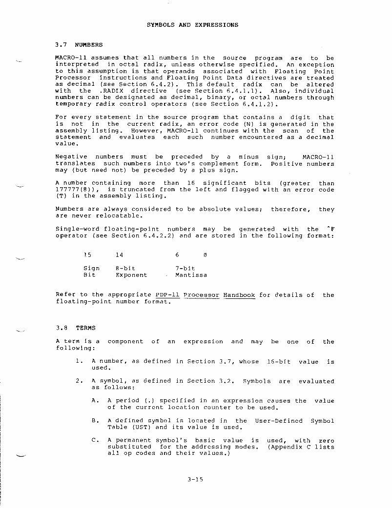
Single-word
floating-point numbers may be generated with the -F
Refer
to the appropriate PDP-11 Processor Handbook for details of the
floating-point
number format
.
3 .8
TERMS
SYMBOLS
AND EXPRESSIONS
A
term is a component of an expression and may be one of the
following :
1 .
A number, as defined in Section 3
.7,
whose 16-bit value is
used .
2 .
A symbol, as defined in Section 3
.2 .
Symbols are evaluated
as
follows
:
A .
A period (
.)
specified in an expression causes the value
of
the current location counter to be used
.
B .
A defined symbol is located in the User-Defined Symbol
Table
(UST) and its value is used
.
C .
A permanent symbol's basic value is used, with zero
substituted
for the addressing modes
.
(Appendix C lists
all
op codes and their values
.)
3-15
operator
(see
Section
6
.4 .2 .2) and
are stored in the following format
:
15 14 6
Sign 8-bit 7-bitBit Exponent Mantissa

D .
An undefined symbol is assigned a value of zero and
inserted
in the User-Defined Symbol Table as an undefined
default
global reference
.
If the
DSABL
GBL directive
(see
Section 6
.2 .1)
is in effect, the automatic global
reference
default function of MACRO-11 is inhibited, and
the
statement containing the undefined symbol is flagged
with
an error code (U) in the assembly listing
.
3 .
A single quote followed by a single ASCII character, or a
double
quote followed by two ASCII characters
.
This type of
expression
construction is explained in detail in Section
6 .3 .3 .
4 .
An expression enclosed in angle brackets (<>)
.
Any
expression
so enclosed is evaluated and reduced to a single
term
before the remainder of the expression in which it
appears
is evaluated
.
Angle
brackets, for example, may be
used
to alter the left-to-right evaluation of expressions (as
in
A*B+C versus A*<B+C>), or to apply a unary operator to an
entire
expression (as in -<A+B>)
.*
5 .
A unary operator followed by a symbol or number
.
3 .9
EXPRESSIONS
SYMBOLS
AND EXPRESSIONS
Expressions
are combinations of terms joined together by binary
operators
(see Table 3-5)
.
Expressions reduce to a 16-bit value
.
The
evaluation
of an expression includes the determination of its
attributes .
A resultant expression value may be any one of four types
(as
described later in this section)
:
relocatable, absolute,
external,
or complex relocatable
.
Expressions
are evaluated from left to right with no operator
hierarchy
rules, except that unary operators take precedence over
binary
operators
.
A term preceded by a unary operator is considered
to
contain that operator
.
(Terms are evaluated, where necessary,
before
their use in expressions
.)
Multiple unary operators are valid
and
are treated as follows
:*
-+-A
is
equivalent to
:
-<+<-A>>
*
The maximum depth of an expression is governed by the MACRO-11
assembler's
expression stack space
.
If an expression exceeds the
assembler's
maximum expression depth, the statement is marked with an
(E)
error, and processing continues
.
3- 1 6

EXAMPLE :
CHAPTER
4
RELOCATION
AND LINKING
The
output of MACRO-11 is an object module that must be processed or
linked
before it can be loaded and executed
.
Essentially, linking
fixes
(makes absolute) the values of relocatable or external symbols
in
the object module, thus transforming the object module, or several
object
modules, into an executable image
.
To
allow the value of an expression to be fixed at link time, MACRO-11
outputs
certain instructions in the object file, together with other
required
parameters
.
For relocatable expressions in the object
module,
the base of the associated relocatable program section is
added
to the value of the relocatable expression provided by MACRO-11
.For
external expression values, the value of the external term in the
expression
(since the external symbol must be defined in one of the
other
object modules being linked together) is determined and then
added
to the absolute portion of the external expression, as provided
by
MACRO-11
.
All
instructions that require modification at link time are flagged in
the
assembly listing, as illustrated in the example below
.
The
apostrophe
(') following the octal expansion of the instruction
indicates
that simple relocation is required
;
the letter G indicates
that
the value of an external symbol must be added to the absolute
portion
of an expression
;
and the letter C indicates that complex
relocation
analysis at link time is required in order to fix the value
of
the expression
.
005065
CLR
RELOC(R5) ;Assuming
that the value of the
000040' ;symbol
"RELOC", 40, is relocatable
;the
relocation bias
;will
be added to this value
.
005065
CLR
EXTERN(R5) ;The
value of the symbol "EXTERN" is
000000G ;assembled
as zero and is
;resolved
at link time
.

RELOCATION
AND LINKING
005065
CLR
EXTERN+6(R5)
;The
value of the symbol "EXTERN"
0000066
;is
resolved at link time
;and
added to
;the
absolute portion (+6) of
;the
expression
.
005065
CLR
-<EXTERN+RELOC>(R5) ;This
expression is complex
000000C
;relocatable
because it requires
;the
negation of an expression
;that
contains a global "EXTERN"
;reference
and a relocatable term
.
For
a complete description of object records output by MACRO-11, refer
to
the applicable system manual (see Section 0
.3
in the Preface)
.

To
understand how the address modes operate and how they assemble, the
action
of the program counter must be understood
.
The key rule to
remember
is
:
"whenever
the processor implicitly uses the program counter
(PC)
to fetch a word from memory, the program counter is
automatically
incremented by 2 after the fetch operation is
completed ."
The
PC always contains the address of the next word to be fetched
.This
word will be either the address of the next instruction to be
executed,
or the second or third word of the current instruction
.
Table
5-1 lists the address modes, and Table 5-2 lists the symbols
used
in this chapter to describe the address modes
.
Each mode of
address
in the chapter is illustrated using either the single operand
instruction
CLR or the double operand instruction MOV
.
CHAPTER 5
ADDRESSING
MODES
Table
5-1
Addressing
Modes
Does
not increase the length of an instruction
.
Adds
one word to the instruction length for
operand
of this form
.each
occurrence of an
Mode FormSection
Reference
Register
mode*
R 5 .1Register
deferred mode*
@R
or (ER)
5 .2Autoincrement
mode*
(ER)
+
5 .3Autoincrement
deferred mode*
@(ER)+ 5 .4Autodecrement
mode*
-(ER) 5 .5Autodecrement
deferred mode*
@-
(ER)
5 .6Index
mode**
E
(ER)
5 .7Index
deferred mode**
@E
(ER)
5 .8Immediate
mode**
#E 5 .9Absolute
mode**
@#E 5 .101Relative
mode**
E 5 .11Relative
deferred mode**
@E 5 .12Branch Address 5 .13

Symbol
Explanation
5 .1
REGISTER MODE
Format :
R
The
register itself (R) contains the operand to be manipulated by the
instruction .
Example :
5 .2
REGISTER DEFERRED MODE
Format :
ADDRESSING
MODES
Table
5-2
Symbols
Used in Chapter 5
F.
Any
expression, as defined in Chapter 3
.
R
A
register expression
;
in other words, any
expression
containing a term preceded by a percent
to
such a
The
register (R) contains the address of the operand to be manipulated
by
the instruction
.
@R
or (ER)
This
symbol may also represent any of the normal
default
register definitions (see Section 3
.4) .
ER
A
register expression or an absolute expression in
the
range 0 to 7, inclusive
.
CLR
R3
;Clears
register 3
.
;All
these instructions clear
;the
word at the address
;contained
in register 1
.
sign
(%) or a
term,
as shown
symbolbelow :
previously equated
R0=%0 ;General register 0 .Rl=R0+1 ;General register 1 .R2=1+$1 ;General register 2 .
Examples :
CLR @R1CLR (R1)CLR ($1)

5 .3
AUTOINCREMENT MODE
Format :
(ER)
+
ADDRESSING
MODES
The
contents of the register (ER) are incremented immediately after
being
used as the address of the operand (see Note below)
.
by
two
.
NOTE
Certain
special instruction/address mode
combinations,
which are rarely or never
used,
do not operate the same on all
PDP-11
processors, as described below
.
In
the autoincrement mode, both the JMP
and
JSR instructions autoincrement the
register
before its use on the PDP-11/40
but
not on the PDP-11/45 or 11/10
.
In
double operand instructions having
the
addressing form Rn,(Rn)+ or
Rn,-(Rn),
where the source and
destination
registers are the same, the
source
operand is evaluated as the
autoincremented
or autodecremented
value,
but the destination register, at
the
time it is used, still contains the
originally
intended effective address
.In
the following example, as executed on
the
PDP-11/40, Register 0 originally
contains
100(8)
:
MOV
R0,(R0)+
;The
quantity 102 is moved
;to
location 100
.
MOV
R0,-(R0)
;The
quantity 76 is moved
;to
location 100
.
The
use of these forms should be
avoided,
since they are not compatible
with
the entire family of PDP-11
processors .
An
error code (Z) is printed in the
assembly
listing with each instruction
which
is not compatible among all
members
of the PDP-11 family
.
5-3
Examples :
CLR (R0)+ ;Each
instruction clears
CLR (R4)+ ;the
word at the address
CLR (R2)+ ;contained
in the specified
;register
and increments
;that
register's contents
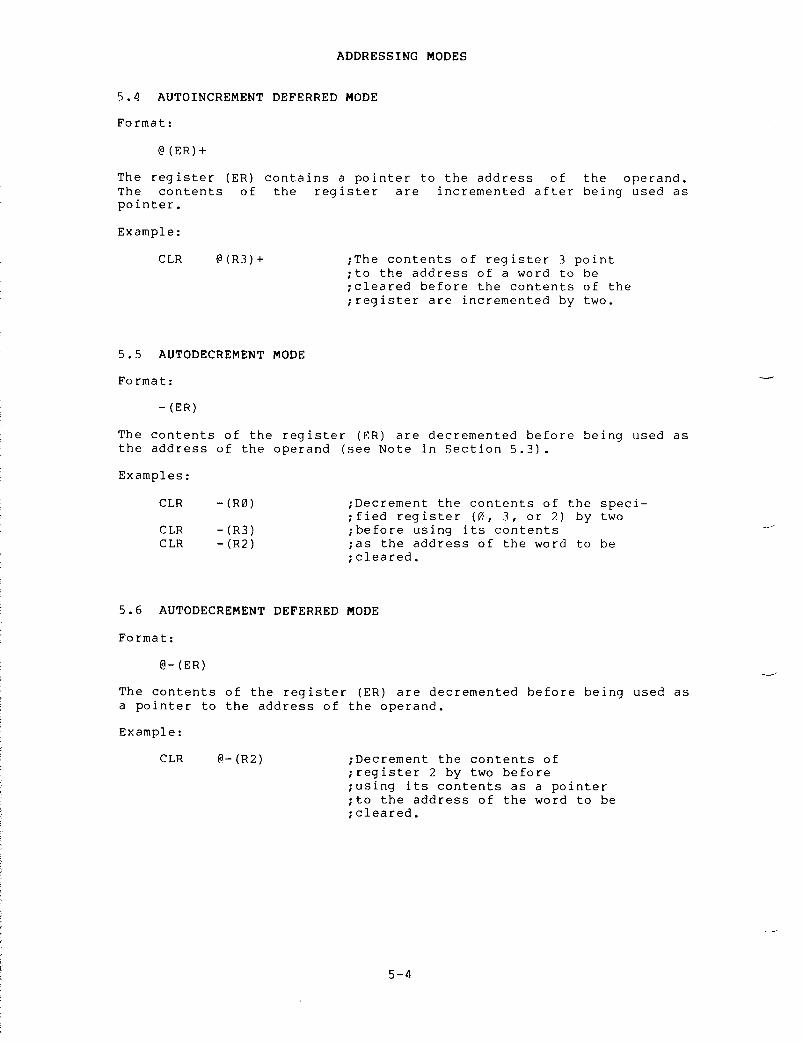
5 .4
AUTOINCREMENT DEFERRED MODE
Format :
The
register (ER) contains a pointer to the address of the operand
.The
contents of the register are incremented after being used as
Format :
Format :
Example :
@
(ER) +
ADDRESSING
MODES
5 .5
AUTODECREMENT MODE
-
(ER)
The
contents of the register (ER) are decremented before being used as
the
address of the operand (see Note in Section 5
.3) .
5 .6
AUTODECREMENT DEFERRED MODE
@-
(ER)
The
contents of the register (ER) are decremented before being used as
a
pointer to the address of the operand
.
CLR
@-(R2)
;Decrement
the contents of
;register
2 by two before
;using
its contents as a pointer
;to
the address of the word to be
;cleared .
Examples :
CLR -(R0) ;Decrement
the contents of the speci-
;fied
register (0, 3, or 2) by two
CLR -(R3) ;before
using its contents
CLR -(R2) ;as
the address of the word to be
;cleared .
pointer .
Example :
CLR @(R3)+ ;The
contents of register 3 point
;to
the address of a word to be
;cleared
before the contents of the
;register
are incremented by two
.

5 .7 INDEX MODE
Format :
E (ER)
An expression (E), plus the contents of a register (ER), yields theeffective address of the operand . In other words, the value E is theoffset of the instruction, and the contents of register ER form thebase . (The value of the expression (E) is stored as the second orthird word of the instruction .)
Examples :
CLR
X+2(R1)
;The effective address of the word;to be cleared is X+2, plus the;contents of register 1 .
MOV
R0,-2(R3)
;The effective address of the;destination location is -2, plus;the contents of register 3 .
5 .8 INDEX DEFERRED MODE
Format :
Example :
@E (ER)
ADDRESSING MODES
An expression (E), plus the contents of a register (ER), yields apointer to the address of the operand . As in index mode above, thevalue E is the offset of the instruction, and the contents of registerER form the base . (The value of the expression (E) is stored as thesecond or third word of the instruction .)
CLR
@114(R4)
;If register 4 contains 100, this;value, plus the offset 114, yields;the pointer 214 . If location 214;contains the address 2000, location;2000 would be cleared .
NOTE
The expression @(ER) may be used, but itwill be assembled as if it were written@0(ER), and a word will be used to storethe of .

5 .9
IMMEDIATE MODE
Format :
#E
Examples :
ADDRESSING
MODES
Immediate
mode allows the operand itself (E) to be stored as the
second
or third word of the instruction
.
The number sign (#) is an
addressing
mode indicator
.
Appearing in the operand field this
character
specifies the immediate addressing mode, indicating to
MACRO-11
that the operand itself immediately follows the instruction
word .
This mode is assembled as an autoincrement of the PC
.
MOV
#100,RO
;Move
the value 100 into register 0
.MOV
#X,RO
;Move
the value of symbol X into
;register
0
.
The
operation of this mode can be shown through the first example,
MOV
#100,RO, which assembles as two words
:
Location
20
:
0 1 2 7 0 0
Location
22
:
0 0 0 1 0 0
Location
?
.4 :
Next instruction
The
source operand (the value 100) is assembled immediately following
the
instruction word
.
Upon execution of the instruction, the
processor
fetches the first word (MOV) and increments the PC by 2 so
that
it points to the second word, location 22, which contains the
source
operand
.
After
the next fetch and increment cycle, the source operand (100) is
moved
into register 0, leaving the PC pointing to location 24 (the
next
instruction)
.
5 .10
ABSOLUTE MODE
Format :
Absolute
mode is the equivalent of immediate mode deferred
.
Theaddress
expression @#E specifies an absolute address which is stored
as
the second or third word of the instruction
.
In other words, the
value
immediately following the instruction word is taken as the
absolute
address of the operand
.
Absolute mode is assembled as an
autoincrement
deferred of the PC
.
Examples :
MOV
@#100,RO
;Move
the contents of absolute
CLR
5-6
;location
100 into register RO
.@#X ;Clear
the contents of the location
;whose
address is specified by
;the
symbol X
.

The
operation of this mode can be shown through the first example,
MOV
@#100,RO, which assembles as two words
:
5 .11
RELATIVE MODE
Format :
E
Examples :
ADDRESSING
MODES
Location
20
:
0 1 3 7 0 0
Location
22
:
0 0 0 1 0 0
Location
24
:
Next instruction
The
absolute address 100 is assembled immediately following the
instruction
word
.
Upon execution of the instruction, the processor
fetches
the first word (MOV) and increments the PC by 2 so that it
points
to the second word, location 22, which contains the absolute
address
of the source operand
.
After the next fetch and increment
cycle,
the contents of absolute address 100 (the source operand) are
moved
into register 0, leaving the PC pointing to location 24 (the
next
instruction)
.
Relative
mode is the normal mode for memory references within your
program .
It is assembled as index mode, using the PC as the index
register .
The offset for the address calculation is assembled as the
second
or third word of the instruction
.
This value is added to the
contents
of the PC to yield the address of the source operand
.
CLR
100
;Clear
absolute location 100
MOV
RO,Y
;Move
the contents of register 0
;to
location Y
The
operation of relative mode can be shown with the statement
MOV
100,R3, which assembles as two words
:
Location
20
:
0 1 6 7 0 3
Location
22
:
0 0 0 0 5 4
Location
24
:
NEXT INSTRUCTION
The
offset, the constant 54, is assembled immediately following the
instruction
word
.
Upon execution of the instruction, the processor
fetches
the first word (MOV) and increments the PC by 2 so that it
points
to the second word, location 22, containing the value 54
.After
the next fetch and increment cycle, the processor calculates the
effective
address of the source operand by taking the contents of
location
22 (the offset) and adding it to the current value of the PC,
which
now points to location 24 (the next instruction)
.
Thus, the
source
operand address is the result of the calculation
OFFSET+PC
= 54+24 = 100(8), causing the contents of location 100 to be
moved
into register 3
.

The
index mode statement
:
MOV
100-
.-4(PC),R3
is
equivalent to the relative mode statement
:
MOV
100,
R3
100- .-4
is the offset for the index mode statement
.
The
current
location
counter (
.)
holds the address of the first word of the
instruction
(20, in this case) and the PC has to move down 4 bytes to
reach
location 24 (the next instruction)
.
So, the offset could be
written
as 100-20-4 or 54(8)
.
Therefore,
for the index mode, the offset (54(8)) added to the
PC(24(8))
yields the effective address (54 + 24 = 100 (8)) of the
operand .
Thus,
both statements move the contents of location 100 into register
3 .
5 .12
RELATIVE DEFERRED MODE
Format :
The
relative deferred mode is similar in operation to the relative
mode
above, except that the expression E is used as a pointer to the
address
of the operand
.
In other words, the operand following the
instruction
word is added to the contents of the PC to yield a pointer
to
the address of the operand
.
Example :
ADDRESSING
MODES
NOTE
The
addressing form @#E differs from
form
E in that the second or third word
of
the instruction contains the absolute
address
of the operand, rather than the
relative
distance between the operand
and
the PC (see Section 5
.10) .
Thus,
the
instruction CLR @#100 clears
absolute
location 100, even if the
instruction
is moved from the point at
which
it was assembled
.
See the
description
of the ENABL AMA function
in
Section 5
.2 .1,
which causes all
relative
mode addresses to be assembled
as
absolute mode addresses
.
MOV
@X,RO
;Relative
to the current value of
;the
PC, move the contents of the
;location
whose address is pointed
;to
by location X into register 0
.

5 .13
BRANCH INSTRUCTION ADDRESSING
ADDRESSING
MODES
The
branch instructions are 1-word instructions
.
The high-order byte
contains
the operator, and the low-order byte contains an 8-bit signed
offset
(seven bits, plus sign), which specifies the branch address
relative
to the current value of the PC
.
The hardware calculates the
branch
address as follows
:
1 .
Extends the sign of the offset through bits 8-15
.
2 .
Multiplies the result by 2, creating a byte offset rather
than
a word offset
.
3 .
Adds the result to the current value of the PC to form the
effective
branch address
.
MACRO-11
performs the reverse operation to form the word offset from
the
specified address
.
Word
offset = (E-PC)/2 truncated to eight bits
.
When
the offset is added to the PC, the PC is moved to the next word
(PC= .+2) .
Hence the -2 in the following calculation
.
Word
offset = (E-
.-2)/2
truncated to eight bits
.
The
following conditions generate an error code (A) in the assembly
listing :
1 .
Branching from one program section to another
2 .
Branching to a location that is defined as an external
(global)
symbol
3 .
Specifying a branch address that is out of range, meaning
that
the branch offset is a value that does not lie within
the
range -128(10) to +1?_7(10)
.
5 .14
USING TRAP INSTRUCTIONS
Since
the EMT and TRAP instructions do not use the low-order byte of
the
instruction word, information is transferred to the trap handlers
in
the low-order byte
.
If the EMT or TRAP instruction is followed by
an
expression, the value of the expression is stored in the low-order
byte
of the word
.
Expressions greater than 377(8) are truncated to
eight
bits, and an error code (T) is generated in the assembly
listing .
For
more information on traps see the PDP-11 Processor Handbook and
the
applicable system manual (see Section 0
.3
in the Preface)
.


A
MACRO-11 directive is placed in
only
one directive is allowed
have
a blank operand field or one
differ
with each directive
.
General
assembler directives
categories :
1 .
Listing control
2 .
Function control
3 .
Data storage
4 .
Radix and numeric control
6 .
Terminator
7 .
Program sectioning and
8 .
Symbol control
9 .
Conditional assembly
10 .
File control
Each
is described in its own
for
an alphabetical listing
section
reference)
.
Directive
.ASCII
.ASCIZ
5 .
Location counter control
CHAPTER
6
GENERAL
ASSEMBLER DIRECTIVES
are
boundaries
sectionof
the
Table
6-1
Directives
in Chapter Six
Function
Stores
delimited string as aof the 8-bit ASCII codecharacters
.
Same
as ASCII except the
followed
by a zero byte
.
the
operator field of a source line
.per
source line
.
Each directive may
or
more operands
.
Legal
operands
divided
into the following
of
this chapter (see Table 6-1
directives
and the associated
(continued
on next page)
SectionReference
sequence 6 .3 .4of
their
string
is
6 .3 .5

block .
GENERAL
ASSEMBLER DIRECTIVES
Table
6-1 (font
.)Directives
in Chapter Six
SectionDirective
Function
Reference
.ASECT
Similar
to PSECT
.
6 .7 .2
.BLKB
Allocates
bytes of data storage
.
6 .5 .3
.BLKW
Allocates
words of data storage
.
6 .5 .3
.BYTE
Stores
successive bytes of data
.
6 .3 .1
.CROSS
Enables
cross reference
.
6 .2 .2
.CSECT
Similar
to PSECT
.
6 .7 .2
.DSABL
Disables specified assembler 6
.2 .1functions .
.ENABL
Enables
specified assembler functions
.
6 .2 .1
.END
Indicates
end of source input
.
6 .6
.ENDC
Indicates
end of conditional assembly
6 .9 .1
.EVEN
Ensures
that current value of the 6
.5 .1location
counter is even
.
.FLT2
Generates
2 words of storage for each
6 .4 .2 .1floating-point
number argument
.
.FLT4
Generates
4 words of storage for each
6 .4 .2 .1floating-point
number argument
.
.GLOBL
Defines
listed symbols as global
.
6 .8 .1
.IDENT
Provides
additional means of labeling
6 .1 .4an
object module
.
.IF
Assembles
block if specified condi-
6 .9 .1tions
are met
.
.IFF
Assembles
block if condition tests 6
.9 .2false .
.IFT
Assembles
block if condition tests 6
.9 .2.true .
.IFTF
Assembles
block regardless of whether
6 .9 .2condition
tests true or false
.
.IIF
Permits
writing a one line conditional
6 .9 .3assembly
block
.
.INCLUDE .
Includes
another MACRO-11 source file
.
6 .10 .2
.LIBRARY
Adds
file to MACRO-11 library search
6 .10 .1list .
(continued
on next page)

GENERAL
ASSEMBLER DIRECTIVES
Table
6-1 (Copt
.)Directives
in Chapter Six
SectionDirective
Function
Reference
.LIMIT
Allocates
two words for storage
.
At
6 .5 .4link
time puts the lowest address of
the
load image in the first of the
saved
words and the address of the
first
free word following the image
in
the second
.
.LIST
Increments
listing count or lists 6
.1 .1certain
types of code
.
.NLIST
Decrements
listing count or suppresses
6.1 .1certain
types of code
.
.NOCROSS
Disables
cross reference
.
6 .2 .2
.ODD
Ensures
that the current value of the
6 .5 .2location
counter is odd
.
.PACKED
Generates
packed decimal data, two 6
.3 .8digits
per byte
.
.PAGE
Starts
a new listing page
.
6 .1 .5
.PSECT
Declares
names for program sections
6 .7 .1and
establishes their attributes
.
.RAD50
Generates
data in Radix-50 packed 6
.3 .6format .
.RADIX
Changes
radices throughout or in 6
.4 .1 .1portions
of the source program
.
.REM
Delimits
a section of comments
.
6 .1 .6
.RESTORE
Retrieves
a previously SAVEd program
6 .7 .4section .
.SAVE
Places
the current program section on
6 .7 .3top
of the program section context
stack .
.SBTTL
Produces
a table of contents 6
.1 .3immediately
preceding the assembly
listing
and puts subheadings on each
page
in the listing
.
.TITLE
Assigns
a name to the object module
6 .1 .2and
puts headings on each page of
the
assembly listing
.
.WEAK
Defines
listed symbols as WEAK
.
6 .8 .2
.WORD
Generates
successive words of data in
6 .3 .2the
object module
.
6-3

6 .1
LISTING CONTROL DIRECTIVES
Listing
control directives control the content, format, and pagination
of
all line printer (see Figure 6-1) and teleprinter (see Figure 6-2)
assembly
listing output
.
On the first line of each page, MACRO-11
prints
the following (from left to right)
:
1 .
Title of the object module, as established through the TITLE
directive
(see Section 6
.1 .2) .
2 .
Assembler version identification
.
3 .
Day of the week
.
4 .
Date
.
5 .
Time of day
.
6 .
Page number
.
GENERAL
ASSEMBLER DIRECTIVES
The
second line of each assembly listing page contains the subtitle
text
specified in the last-encountered SBTTL directive (see Section
6 .1 .3) .
In
the line printer format (Figure 6-1) binary extensions for
statements
generating more than one word are listed horizontally
.
In
the teleprinter format (Figure 6-2) binary extensions for
statements
generating more than one word are listed vertically
.
There
is
no explicit truncation of output to 80 characters by the assembler
.

Figure
6-
1
Example of Line Printer Assembly Listing
2 i
GETSYM
3 Scan
oft a RAD50 swabol
.
Leave with scan pointer set at next non-blank
45
char
Past end
seen ;
In this
of
swabol
.
Sumbol buffer clear and Z set if no swabol
case
scan Pointer is unaltered
.678 000126 010146 GETSYM22MOV R1 ;-(SP) ;Save
work resister
9 000130 016767 0000006 0000000 MOV CHRPNT ;SYMBEG ;Save
scan Pointer in case of rescan
10 000136 012701 0000046 MOV ;SYMBOLt4 ;R1 ;Point
at end of swabol buffer
11 000142 005041 CLR -(R1) ;Now
clear it
12 000144 005041 CLR -(R1)13 000146 136527 000000' 000040 BITD CTTBL(R5) ;
*CT
.ALP ;Test
first char for alphabetic
14 000154 001436 BED 4f ;Exit
if not with Z set
15 000156 116500 000262' 1$S
MOVB
CTTBL2(R5) ;RO ;Map
to RAD50
16 000162 003431 BLE 3$ ;Exit
if not
17 000164 006300 ASL RO ;Make
word index
18 000166 016011 000462' MOV R50TB1(RO)r(Rl) ;Load
the high char
19 000172 GETCHR ;Get
another char
20 000176 116500 000262' MOVB CTTBL2(R5) ;RO ;Handle
it as above
21 000202 003421 BLE 3t22 000204 006300 ASL RO23 000206 066011 000602' ADD R50TB2(RO) ;(R1)24 000212 GETCHR ;Now
get low order char
25 000216 116500 000262' MOVB CTTBL2(R5) ;RO ;Map
and test it
26 000222 003411 BLE 3f27 000224 060021 ADD R0 ;(R1)+ ;Just
add in the low char
.
advance Pointer
28 000226 2t2
GETCHR
;Get
following char
29 000232 020127 0000046 CMP Ri ;#SYMBOL+4 ;Test
it at end of swobol buffer
30 000236 001347 BNE 1$ ;Go
again if no
31 000240 105765 000262' TSTB CTTBL2(R5) ;Flush
to end of swabol if wes
32 000244 003370 BGT 2$33 000246 3$ :
SETND
;Now
scan to a non blank char
34 000252 012601 4$I
MOV
(SP)+ ;R1 ;Restore
work register
35 000254 016700 0000006 MOV SYMBOL ;RO ;Set
Z it no swwbol found
36 000260 000207 RETURN ;Exit37

Figure
6-
1
(Cont
.)
Example of Line Printer Assembly Listing
3839
;+:
Table
CTTBL24041
:
Index,
:
If EQ
with
7
0
then
bit
ASCII value to get corresponding RAD50 value
spacer
if LT 0 then not RAD50
;
Other bits reserved
.42 ;-4344 NLIST BEX45 000262 200 200 200 CTTBL2 : BYTE 200r200r200r200r200r200r200r200 ;46 000272 200 200 200 BYTE 200r200r200r200r200r200r200r200 ;47 000302 200 200 200 BYTE 200r200r200r200r200r200r200r200 ;48 000312 200 200 200 BYTE 200r200r200r200r200r200r200r200 ;49 000322 000 200 200 BYTE 000r200r200r200r0339200r200r200 ;
$
50 000332 200 200 200 BYTE 200r200r200r2009200r200r034r200 ;51 000342 036 037 040 BYTE 036PO37YO40YO41YO42YO43PO44PO45 ;0123456752 000352 046 047 200 BYTE 046r047r200r200r200r200r200r200 ;8953 000362 200 001 002 BYTE 200r001r00200039004r005r006r007 ;
ABCDEFG
54 000372 010 011 012 BYTE O1Or011r012r013r014r015r016r017 ;HIJKLMNO55 000402 020 021 022 BYTE 020P0219022YO23PO24PO25PO269027 ;FQRSTUVW56 000412 030 031 032 BYTE 030r03lvO32r200r200r20OP20OP200 ;XYZ57 000422 200 001 002 BYTE 200POO19002YO03PO04YO05YO06YO07 ;
abcdefg

J
Figure 6- 2 Example of Teleprinter Assembly Listing
2 ; GETSYM3 ; Scan off a RAD50 swnbol . Leave with scan pointer set at next non-blank456; char Past endi seen ; In this;-
of swwbol . Swebol buffer clear and Z set it no swwbolcase scan Pointer is unaltered .78 000126 010146 GETSYMSSMOV R1p-(SP) ;Save work register9 000130 016767 MOV CHRPNTFSYMBEG ;Save scan Pointer in case of rescanOOOOOOG zOOOOOOG10 000136 012701 MOV " SYMBOL+4vR1 ;Point at end of swmbol buffer000004G t"11 000142 005041 CLR -(R1) ;Now clear it12 000144 005041 CLR -(RI) En13 000146 136527 BITB CTTBL(R5)r " CT .ALP ;Test first char for alphabetic000000' 3000040 C14 000154 001436 BEG 4$ ;Exit if not with Z set15 000156 116500 1$ : MOVB CTTBL2(R5)#RO ;Map to RAD50000262' t716 000162 003431 IDLE 3$ ;Exit if not H
17 000164 006300 ASL RO ;Make word index to18 000166 016011 MOV R50TID1(RO) .(R1) ;Load the high char n000462' H19 000172 GETCHR ;Get another char20 000176 116500 MOVB CTTBL2(R5)YRO ;Handle it as above000262'21 000202 003421 BLE 3$22 000204 006300 ASL RO23 000206 066011 ADD R50TB2(RO)r(R1)000602'

Figure
6-
2
(Cont
.)
Example of Teleprinter Assembly Listing
24 000212 GETCHR :Now
get low order char
25 000216 116500 MOVD
CTTBL2(R5)
.RO ;Map
and test it
000262'26 000222 003411 BLE
3$
27 000224 060021 ADD
ROr(Rl)+ gust add in the low char
.
advance Pointer
28 000226 2f :
GETCHR
;Get
following char
29 000232 020127 CMP
R1r
" SYMBOL+4 ;Test
if at end of symbol buffer
000004G30 000236 001347 BNE
1f
;Go
again if no
31 000240 105765 TSTB
CTTBL2(R5)
;Flush
to end of symbol if yes
000262'32 000244 003370 BGT
24
33 000246 3t :
SETNB
;Now
scan to a non blank char
34 000252 012601 4f :
MOV (SP)+PRI
;Restore
work register
35 000254 016700 MOV SYMBOL .R O ;Set
Z if no symbol found
OOOOOOG36 000260 000207 RETURN ;Exit3738 ;+39 ;
Table CTTBL2
40 ;
Index with 7 bit ASCII value to get corresponding RAD50 value
41 ;
If EO 0 then spacer if LT 0 then not RAD50
;
Other bits reserved
.42 ;-4344 NLIST
BEX

6 .1 .1
LIST and NLIST DirectivesFormats :
where :
arg
represents one or more of the optional symbolicarguments defined in Table 6-2 .As indicated above, the listing control directives may be used withoutarguments, in which case the listing directives alter the listinglevel count . The listing level count is initialized to zero . At eachoccurrence of a LIST directive, the listing level count isincremented ; at each occurrence of an NLIST directive, the listinglevel count is decremented . When the level count is negative, thelisting is suppressed (unless the line contains an error) .Conversely, when the level count is greater than zero, the listing isgenerated regardless of the context of the line .
Finally, when thecount is zero, the line is either listed or suppressed, depending onthe listing controls currently in effect for the program .
Thefollowing macro definition employs the LIST and NLIST directives toselectively list portions of the macro body when the macro isexpanded :
.LIST.LIST arg.NLIST.NLIST arg
GENERAL ASSEMBLER DIRECTIVES
Note that the lines following line E will list because the listinglevel count remains 0 . If a LIST directive is placed at thebeginning of a program, all macro expansions will be listed unless a.NLIST directive is encountered .
.LISTMUST
.LIST ;Listing level count is 0 .E-this line should list ;Listing level count is 0 .F-this line should list ;Listing level count is 0 .G-this line should list ;Listing level count is 0 .. ENDM
.LIST ME ;List macro expansion .LTEST ;Call the macroA-this line should list ;Listing level count is 0 .E-this line should list ;Listing level count is 0 .F-this line should list ;Listing level count is 0 .G-this line should list ;Listing level count is 0 .
.MACRO LTEST ;List testA-this line should list ;Listing level count is 0~.NLIST ;Listing level count is -1 .B-this line should not list.NLIST ;Listing level count is -2 .C-this line should not list.LIST ;Listing level count is -1 .D-this line should not list

An
important purpose of the level count is to allow macro expansions
to
be listed selectively and yet exit with the listing level count
restored
to the value existing prior to the macro call
.
When
used with arguments, the listing directives do not alter the
listing
level count
.
However, the LIST and NLIST directives can be
used
to override current listing control, as shown in the example
below :
GENERAL
ASSEMBLER DIRECTIVES
The
symbolic arguments allowed for use with the listing directives are
described
in Table 6-2
.
These arguments can be used singly or in
combination
with each other
.
If multiple arguments are specified in a
listing
directive, each argument must be separated by a comma, tab, or
space .
For any argument not specifically included in the control
statement,
the associated default assumption (List or No list) is
applicable
throughout the source program
.
The default assumptions for
the
listing control directives also appear in Table 6-2
.
Table
6-2
Symbolic
Arguments of Listing Control Directives
Argument
Default
SEQ*
List
Function
Controls
the listing of the sequential
numbers
assigned to the source lines
.If
this number field is suppressed
through
an NLIST SEQ directive,
MACRO-11
generates a tab, effectively
allocating
blank space for the field
.Thus,
the positional relationships of
the
other fields in the listing remain
undisturbed .
During the assembly
process,
MACRO-11 examines each source
line
for possible error conditions
.For
any line in error, the error code
is
printed preceding the number field
.*
If the NLIST arguments SEQ, LOC, BIN, and SRC are in effect at
the
same time, that is, if all four significant fields in the
listing
are to be suppressed, the printing of the resulting blank
line
is inhibited
.(continued
on next page)
.MACRO
XX
.LIST ;List
next line
.
.NLIST ;Do
not list remainder of macro
;expansion .
.
ENDM
.NLIST
ME
;Do
not list macro expansions
.XX

Table
6-2 (Copt
.)Symbolic
Arguments of Listing Control Directives
Argument
Default
GENERAL
ASSEMBLER DIRECTIVES
Function
MACRO-11
does not assign line
to
files that have had such
assigned
by other programs (an
program,
for instance)
.
Controls
the listing of the current
location
counter field
.
Normally,
this
field is not suppressed
.However,
if it is suppressed through
the
NLIST LOC directive, MACRO-11
does
not generate a tab, nor does it
allocate
space for the field, as is
the
case with the SEQ field described
above .
Thus, the suppression of the
current
location counter (LOC) field
effectively
left-justifies all
subsequent
fields (while preserving
positional
relationships) to the
position
normally occupied by the
counter's
field
.
Controls
the listing of generated
binary
code
.
If this field is
suppressed
through an NLIST BIN
directive,
left-justification of the
source
code field occurs
manner
described above
field .
Controls
the listing of binary
extensions
(the locations and binary
contents
beyond those that will fit on
the
source statement line)
.
This is a
subset
of the BIN argument
.
Controls
6-11
numbersnumberseditor
in
the same
for
the LOC
the
listing of source lines
.
Controls
the listing of comments
.This
is a subset of the SRC argument
.The
NLIST COM directive reduces
listing
time and space when comments
are
not desired
.
Controls
the listing of macro
definitions
and repeat range
expansions .
Controls
the listing of macro calls
and
repeat range expansions
.
*
If the NLIST arguments SEQ, I,OC, BIN, and SRC are in effect at
the
same time, that is, if all four significant fields in the
listing
are to be suppressed, the printing of the resulting blank
line
is inhibited
.(continued
on next page)
LOC* List
BIN* List
BEX List
SRC* List
COM List
MD List
MC List

Table
6-2 (Cont
.)Symbolic
Arguments of Listing Control Directives
Argument
Default
ME
No
list
MEB
No
list
CND
List
GENERAL
ASSEMBLER DIRECTIVES
Any
argument specified in a
.LIST/ .NLIST
directive other than
listed
in Table 6-2 causes the directive to be flagged with an
code
(A) in the assembly listing
.
The
listing control options can also
through
switches included in the
Section
8
.1 .3
and/or the appropriate
switches
overrides all corresponding
directives
specified in the source program
.
Function
Controls
the listing of macro
expansions .
Controls
the listing of macro
expansion
binary code
.
A LIST MEB
directive
lists only those macro
expansion
statements that generate
binary
code
.
This is a subset of the
ME
argument
.
Controls
the listing of unsatisfied
conditional
coding and associated IF
and
ENDC directives in the source
program .
A NLIST CND directive lists
only
satisfied conditional coding
.
Controls
the listing of all listing
directives
having no arguments, in
other
words, the directives that alter
the
listing level count
.
Controls
the listing of the table of
contents
during assembly pass 1 (see
Section
6
.1 .3
describing the
SBTTLdirective) .
This
argument does not
affect
the printing of the full
assembly
listing during assembly pass
2 .
Controls
the listing of the symbol
table
resulting from the assembly of
the
source program
.
Controls
the listing output format
.The
default is set to line printer
format .
Figure 6-1 illustrates the
line
printer output format
.
Figure
6-2
illustrates the teleprinter output
format .
Figure
6-3 shows a listing, produced in line printer format,
reflecting
the use of the LIST and NLIST directives in the source
program
and the effects such directives have on the assembly listing
output .
6-12
thoseerror
be
specified at assembly time
command
string to MACRO-11 (see
system
manual)
.
The use of these
listing
control (
.LIST
or NLIST)
LD No
list
TOC List
SYM List
TTM No
list

LISTING CONTROL EXAMPLE MACRO 405 .00 Saturday 08-Jan-83 9 :55 Pase 1
w
Figure 6-3 Listing Produced with Listing Control Directives
123
TITLE LISTING CONTROL EXAMPLE
LIST ME :List macro expansions45 ; f6 i Listing control test macro7 ;-89 MACRO LSTMAC ARG
10 NLItT ARG11 WORD lr2r3r4 ;This is a test comment12 LIST ARG13 . ENDM t'+1415 000000 LSTMAC LOC ;Location counter test
.NlIST LOC000001 000002 000003 WORD lr2r3r4 ;This is a test comment
DD000004 OLIST LOC C"
1 6 xJ17 000010 LSTMAC BIN ;Generated t+inarw test G.NLIST BIN H
000010 WORD 1r2r3r4 ;This is a test comment.LIST BIN n
18 HH19 000020 LSTMAC BEX ;Binary extensions test.NLIST BEX
000020 000001 000002 000003 WORD 1r2r3r4 ;This is a test comment.LIST BEX
2021 000030 LSTMAC SRC ;Source lines test
000030 000001 000002 000003000036 000004

Figure 6-3 (Cont .) Listing Produced with Listing Control Directives
.LIST SRC2223 000040 LSTMAC COM ;Comment lines test.NLIST COM000040 000001 000002 000003 WORD lr2r3r4000046 000004 .LIST COM2425 000050 LSTMAC 'COMPBEX) ;Comment lines and extended binary test.NLIST COMPHEX000050 000001 000002 000003 WORD 1y2y3p4 M.LIST COMPBEX2 6 t"27 LIST TTM ;Enable narrow listin52829 000060 LSTMAC SEO ;Sequence numbers test.NLIST SEG000060 000001 WORD 1r2 .3Y4 ;This is a test comment000062 000002000064 000003000066 000004 G.LIST SEG H3031 000070 LSTMAC HEX ;Binarw extensions test n.NLIST HEX H000070 000001 WORD 1p2r3r4 ;This is a test comment.LIST HEX to3233 000001 END

6 .1 .2
TITLE DirectiveFormat :
.TITLE string
GENERAL ASSEMBLER DIRECTIVES
.TITLE
where : string represents an identifier of 1 or more Radix-50characters . Appendix A .2 contains a table of Radix-50characters .The TITLE directive assigns a name to the object module .
The nameassigned is the first six non-blank, Radix-50 characters following the.TITLE directive . All spaces and/or tabs up to the firstnon-space/non-tab character following the TITLE directive are ignoredby MACRO-11 when evaluating the text string .
Any characters beyondthe first six are checked for ASCII legality, but they are not used aspart of the object module name . For example, the directive :.TITLE PROGRAM TO PERFORM DAILY ACCOUNTING
causes the assembled object module to be named PROGRA . This6-character name bears no relationship to the filename of the objectmodule, as specified in the command string to MACRO-11 . The name ofan object module (specified in the TITLE directive) appears in theload map produced at link time . This is also the module name whichthe Librarian will recognize .If the TITLE directive is not specified, MACRO-11 assigns the defaultname MAIN . t o the object module . If more than one TITLE directiveis specified in the source program, the last TITLE directiveencountered during assembly pass 1 establishes the name for the entireobject module .If the TITLE directive is specified without an object module name, orif the first non-space/non-tab character in the object module name isnot Radix-50 character, the directive is flagged with an error code(A) in the assembly listing .
6 .1 .3
SBTTL DirectiveFormat :
.SBTTL stringwhere : string represents an identifier of 1 or more printable ASCIIcharacters .
.SBTTL

The
SBTTL directive is used to produce a table of contents
immediately
preceding the assembly listing and to print the text
following
the SBTTL directive on the second line of the header of
each
page in the listing
.
The subheading in the text will be listed
until
altered by a subsequent SBTTL directive in the program
.
For
example,
the directive
:
causes
the text
.SBTTL
Conditional assemblies
Conditional
assemblies
to
be printed as the second line in the header of the assembly
listing .
During
assembly pass 1, a table of contents containing the line
sequence
number, the page number, and the text accompanying each
.SBTTL
directive is printed for the assembly listing
.
The listing of
the
table of contents is suppressed whenever an NLIST TOC directive
is
encountered in the source program (see Table 6-2)
.
An example of a
table
of contents listing is shown in Figure 6-4
.
Format :
MTTEMT
- RT-11 MULTI-TTY EMT SE MACRO V05
.00
Saturday 08-Jan-83 10
:00TABLE
OF CONTENTS
50-
1
MTOUT
- Single character output EMT
51-
1
MTRCTO
- Reset CTRL/O EMT
52-
1
MTATCH
- Attach to terminal EMT
54-
1
MTDTCH
- Detach from a terminal EMT
55-
1
MTPRNT
- Print message EMT
56-
1
MTSTAT
- Return multi-terminal system status EMT
57--
1
MTTIN
- Single character input
58-
1
MTTGET
- Get a character from the ring buffer
59-
1
TTRSET
- Reset terminal status bits
60-
1
MTTPUT
- Single character output
62-
1
MTRSET
- Stop and detach all terminals attached to a job
63-
1
ESCAPE
SEQUENCE TEST SUBROUTINE
6 .1 .4
IDENT
Directive
Figure
6-4 Assembly Listing Table of Contents
.IDENT
/string/
where :
string represents
charactersor
version
globalprinted
GENERAL
ASSEMBLER DIRECTIVES
a
string of six or fewer Radix-50
which
establish the program identification
number .
This string is included in the
symbol
directory of the object module and is
in
the link map and librarian listing
.
.IDENT

GENERAL
ASSEMBLER DIRECTIVES
/
/
represent delimiting characters
.
These delimiters may
be
any paired printing characters, other than the
equal
sign
the
left angle bracket (<), or the
semicolon
as
long as the delimiting character is
not
contained within the text string itself (see Note
in
Section 6
.3 .4) .
If
the delimiting characters do
not
match, or if an illegal delimiting character is
used,
the
IDENT
directive is flagged with an error
code
(A) in the assembly listing
.
In
addition to the name assigned to the object module with the
TITLEdirective
(see Section 6
.1 .3),
the IDENT directive allows the user to
label
the object module with the program version number
.
An
example of the IDENT directive is shown below
:
.IDENT
/V01
.00/
The
character string is converted to Radix-50 representation and
included
in the global symbol directory of the object module
.
This
character
string also appears in the link map produced at link time
and
the Librarian directory listings
.
When
more than one IDENT directive is encountered in a given program,
the
last such directive encountered establishes the character string
which
forms part of the object module identification
.
The
RT-11 linker allows only one IDENT string in a program
.
Thelinker
uses the first IDENT directive encountered during the first
pass
to establish the character string that will be identified with
all
of the object modules
.
The
RSX-11M task builder allows an IDENT string for each module in
the
program
.
The TASK Builder uses the first IDENT directive in each
module
to establish the character string that will be identified with
that
module
.
Like the RT-11 Linker, the RSX-11M Task Builder uses the
.IDENT
directives encountered on the first pass
.
5 .1 .5
PAGE
Directive/Page Ejection
Format :
.PAGE
.PAGE
The
PAGE directive is used within the source program to perform a
page
eject at desired points in the listing
.
This directive takes no
arguments
and causes a skip to the top of the next page when
encountered .
It also causes the page number to be incremented and the
line
sequence counter to be cleared
.
The PAGE directive does not
appear
in the listing
.
When
used within a macro definition, the PAGE directive is ignored
during
the assembly of the macro definition
.
Rather, the page eject
operation
is performed as the macro itself is expanded
.
In this case,
the
page number is also incremented
.

Pag
e
2 .
3 .
6 .1 .6
REM
Directive/Begin Remark Lines
Format :
where :
ejection
is accomplished in three other ways
:
After
reaching a count of 58 lines in the listing, MACRO-11
automatically
performs a page eject to skip over page
perforations
on line printer paper and to formulate
teleprinter
output into pages
.
The page number is not
changed .
A
page eject is performed when a form-feed character is
encountered .
If the form-feed character appears within a
macro
definition, a page eject occurs during the assembly of
the
macro definition, but not during the expansion of the
macro
itself
.
A page eject resulting from the use of the
form-feed
character causes the page number to be incremented
and
the line sequence counter to be cleared
.
A
page eject is performed when encountering a new source
file .
In this
.
case the page number is incremented and the
line
sequence count is reset
.
.REM
comment-character
comment-character
represents
a character that marks the
end
of the comment block when the
character
reoccurs
.
The
REM directive allows a programmer to insert a block of comments
into
a MACRO-11 source program without having to precede the
lines
with the comment character (
;) .
The text between the
delimiting
characters is treated as
any
number of lines
.
For
.TITLE
Remark
example
.REM
&
All
the text that resides here is interpreted by MACRO-11
to
be comment lines until another ampersand character is
found .
Any character may be used in place of the ampersand
.&C
LR
PC.END
6 .2
FUNCTION DIRECTIVES
example :
The
following function directives
invoke
or inhibit certain MACRO-11
to
the assembly process itself
.
GENERAL
ASSEMBLER DIRECTIVES
are
included in a source program to
functions
and operations incidental
.REM
commentspecified
comments .
The comments may span

6 .2 .1
ENABL
and DSABL Directives
Formats :
.ENABL
arg
.DSABL
arg
GENERAL
ASSEMBLER DIRECTIVES
where :
arg represents one or more of the optional symbolic
arguments
defined in Table 6-3
.
Specifying
any argument in an
.ENABL/ .DSABL
directive other than those
listed
in Table 6-3 causes that directive to be flagged with an error
code
(A) in the assembly listing
.
Table
6-3
Symbolic
Arguments of Function Control Directives
Function
.ENABL
.DSABL
Enabling
this function produces absolute
binary
output in FILES-11 format
.
To
convert
this output to Formatted Binary
format
(as required by the Absolute
Loader),
use the FLX utility
.
Enabling
this function causes all relative
addresses
(address mode 67) to be assembled
as
absolute addresses (address mode 37)
.This
function is useful during the
debugging
phase of program development
.
Enabling
this function causes source
columns
from 73 to the end of the line, to
be
treated as a comment
.
The most common
use
of this feature is to permit sequence
numbers
in card columns 73-80
.
Disabling
this function inhibits the
generation
of cross-reference output
.
This
function
only has meaning if
cross-reference
output generation is
specified
in the command string
.
Enabling
this function causes floating-
point
truncation
;
disabling this function
causes
floating-point rounding
.
Disabling
this function causes MACRO-11 to
convert
all ASCII input to upper-case
before
processing it
.
6-19
(continued
on next page)
Argument Default
ABS Disable
AMA Disable
CDR Disable
CRF Enable
FPT Disable
LC Enable

GENERAL
ASSEMBLER DIRECTIVES
Table
6-3 (Cont
.)Symbolic
Arguments of Function Control Directives
encountered
within the same module
.
(continued
on next page)
Argument Default Function
LCM Disable This
argument, if enabled, causes the
MACRO-11
conditional assembly directives
.IF
IDN and IF DIF to be alphabetically
case
sensitive
.
By default, these
directives
are not case sensitive
.
LSB Disable This
argument permits the enabling or
disabling
of a local symbol block
.Although
a local symbol block is normally
established
by encountering a new symbolic
label,
a PSECT directive or a RESTORE
directive
in the source program, an ENABL
LSB
directive establishes a new local
symbol
block which is not terminated until
(1)
another ENABL LSB is encountered, or
(2)
another symbolic label, PSECT
directive
or RESTORE directive is
encountered
following a paired DSABL LSB
directive .
The
basic function of this directive with
regard
to PSECTS is limited to those
instances
where it is desirable to leave a
program
section temporarily to store data,
followed
by a return to the original
program
section
.
This temporary dismissal
of
the current program section may also be
accomplished
through the SAVE and RESTORE
directives
(see Sections 6
.7 .3
and 6
.7 .4) .
Attempts
to define local symbols in an
alternate
program section are flagged with
an
error code (P) in the assembly listing
.
An
example of the ENABL LSB and DSABL LSB
directives,
as typically used in a source
program,
is shown in Figure 6-5
.
MCL Disable This
argument, if enabled, causes MACRO-11
to
search all known macro libraries for a
macro
definition that matches any undefined
symbols
appearing in the opcode field of a
MACRO-11
statement
.
By default, this
option
is disabled
.
If MACRO-11 finds an
unknown
symbol in the opcode field, it
either
declares a (U) undefined symbol
error,
or declares the symbol an external
symbol,
depending on the
.ENABL/ .DSABLoption
setting of GBL (described below)
.
PNC Enable Disabling
this function inhibits binary
output
until an ENABL PNC statement is

GENERAL
ASSEMBLER DIRECTIVES
Table
6-3 (font
.)Symbolic
Arguments of Function Control Directives
Function
the
DSABL REG directive
normal
MACRO-11 default
tions ;
if not disabled, the
tions
listed below remain in
GBL
Enable
This
argument, if disabled, causes MACRO-11
to
mark all undefined references in
assembly
pass 2 with a (U) error in the
assembly
listing
.
The
default for this
option
is enabled, which causes MACRO-11 to
treat
all undefined symbol references as
global,
allowing the linker to resolve
them .
.ENABL/ .DSABL
MACRO V05
.00
Saturday 08-Jan-83 10
:26
Page 1
statement
may be used as the
ement
of the DSABL REG
e
use of these directives,
not
recommended
.
For logical
use
the normal default
itions
listed above
.
I
TITLE .ENABL/ .DSABL3
i+4
i
ILLUSTRATE
.ENABL/ .DSABL
LC
567
ENABL
LC
:STORE
MACRO IN LOWER CASE
89
MACRO
TEXT fft
10
ASCII
/This $$$ a lower case string/
11
ENDM1213
LIST
ME
14
NLIST
BEX
1516
000000
TEXT
is
:Invoke
macro in lower case
000000
124
150
151
ASCII
/This is a lower case string/
17is
DSADL
LC
:Now
disable lower case
1920
000033
TEXT
WAS
;RE-INVOKE
MACRO IN UPPER CASE
000033
124
110
111
ASCII
/THIS WAS A LOWER CASE STRING/
2122
000001
END
Figure
6-
5
Example of ENABL and DSABL Directives
Argument Default
REG Enable When
specified,
inhibits
the
register
defin
default
defin
effect .
RO=$0Rl=%1R2=%2R3=%3R4=%4R5=%5SP=%6PC=%7
The
ENABL REG
logical
comp
directive .
T
however,
is
consistency,register
defi

6 .2 .2
Cross-Reference Directives
:
CROSS
and NOCROSS
Formats :
where :
syml,
represents
legal symbolic names
.
When multiple
sym2 . . . .
symbols are specified, they are separated by any
symn
legal
separator (comma, space, and/or tab)
.
The
CROSS and the
NOCROSS
directives control which symbols are
included
in the cross-reference listing produced by the MACRO-11
assembler .
These directives have an effect only if the /C[R] or the
/CROSS
qualifier was used in the command line to select the
cross-reference
capability
.
By
default, the cross-reference listing includes the definition and
all
the references to every user symbol in the module
.
The
cross-reference
listing can be disabled for all symbols or for a
specified
list of symbols
.
When
the NOCROSS directive is used without a symbol list, the
cross-reference
listing of all the symbols in the module is disabled
.The
cross-reference listing of all the symbols in the module is
reenabled
when the
CROSS
directive is used without a symbol list
.Any
symbol definition or reference that appears after a
NOCROSSdirective
that is used without a symbol list and before the next
.CROSS
directive that is used without a symbol list, is excluded from
the
cross-reference listing
.
The
NOCROSS directive, used with a symbol list, disables the
cross-reference
listing for the listed symbols
.
When the CROSS
directive
is used with a symbol list, the cross-reference listing of
the
listed symbols is reenabled
.
In
the following example, the definition of LABEL1 and the reference
to
LOC1 and LOC2 are not included in the cross-reference listing
.
Example :
Example :
.CROSS
.CROSS
syml,sym2
. . . .
symn
.NOCROSS
.NOCROSS
syml,sym2
. . . .
symn
GENERAL
ASSEMBLER DIRECTIVES
.NOCROSS
;Stop
cross reference
LABELI :
MOV
LOC1,LOC2
;Copy
data
.CROSS
;Reenable
cross reference
In
the next example, the definition of LABEL2 and the reference to
LOC2
are included in the cross reference, but the reference to LOC1 is
not
included
.
LABEL2 :
6-22
.CROSS
.NOCROSS
.NOCROSS LOC1 ;Do
not cross reference LOC1
MOV LOC1,LOC2 ;Copy
data
.CROSS LOC1 ;Reenable
cross reference
;of
LOC1
.

The
CROSS directive, used without a symbol list, cannot be used to
reenable
the cross-reference listing of a symbol specified in the
symbol
list of a NOCROSS directive
.
In addition, if the
cross-reference
listing of all the symbols in a module is disabled,
the
CROSS directive used with a symbol list will have no effect until
the
cross-reference listing is reenabled by the CROSS directive used
without
a symbol list
.
The
CROSS directive, with no symbol list, is equivalent to the ENABL
CRF
directive, and the NOCROSS directive, with no symbol list, is
equivalent
to the DSABL CRF directive
.
6 .3
DATA STORAGE DIRECTIVES
A
wide range of data and data types can be generated with the
directives,
ASCII conversion characters, and radix-control operators
described
in the following sections
.
6 .3 .1
BYTE
Directive
Format :
.BYTE
where :
The
BYTE directive is used to generate successive bytes of binary
data
in the object module
.
Example :
SAM=5.=410
GENERAL
ASSEMBLER DIRECTIVES
exp
;Stores
the binary value of the
;expression
in the next byte
.
.BYTE
.BYTE
expl,exp2,expn ;Stores
the binary values of the list
;of
expressions in successive bytes
.
exp,
represent
expressions that must be reduced to 8 bits
expl,
of
data or less
.
Each
expression will be read as a
16-bit
word
expression,
the high-order byte to be
truncated .
The high-order byte must be either all
zeros
or a truncation (T) error results
.expn
multiple
expressions must be separated by commas
.
.BYTE
~D48,SAM
;The
value 060 (octal equivalent of 48
;decimal)
is stored in location 410
.;The
value 005 is stored in location
;411 .
The
construction "'D in the first operand of the BYTE directive above
illustrates
the use of a temporary radix-control operator
.
The
function
of such special unary operators is described in Section
6 .4 .1 .2 .

At
link time, it is likely that a relocatable expression will result
in
a value having more than eight bits, in which case the task builder
or
linker issues a truncation (T) error for the object module in
question .
For example, the following statements create such a
possibility :
A :
If
an expression following the BYTE directive is null, it is
interpreted
as a zero
:
.=420.BYTE
�
,
;Zeros
are stored in bytes 420, 421,
;422,
and 423
.
Note
that in the above example, four bytes of storage result from the
.BYTE
directive
.
The three commas in the operand field represent an
implicit
declaration of four null values, each separated from the
other
by a comma
.
Hence, four bytes, each containing a value of zero
(0),
are reserved in the object module
.
6 .3 .2
WORD
Directive
Formats :
GENERAL
ASSEMBLER DIRECTIVES
.WORD
.WORD
exp
;Stores
the binary equivalent of the
;expression
in the next word
.
.WORD
expl,exp2,expn ;Stores
the binary equivalents of the
;list
of expressions in successive
;words .
where :
exp,
represent
expressions that must reduce to 16 bits of
expl,
data
or less
.
Multiple expressions must be separated
by
commas
.
expn
The
WORD directive is used to generate successive words of data in
the
object module
.
Example :
SAL=O.=500
.WORD
177535, .+4,SAL ;Stores
the values 177535, 506, and
;0
in words 500, 502, and 504,
;respectively .
.BYTE
23
;Stores
octal 23 in next byte
.
.BYTE
A
;Relocatable
value A will probably
;cause
truncation error
.

If
an expression following the WORD directive contains a null value,
it
is interpreted as a zero, as shown in the following example
:
.=500.WORD
GENERAL
ASSEMBLER DIRECTIVES
;Stores
the values 0, 5, and 0 in
;location
500, 502, and 504,
;respectively .
A
statement with a blank operator field (one that contains a symbol
other
than a macro call, an instruction mnemonic, a MACRO-11
directive,
or a semicolon) is interpreted during assembly as an
implicit
WORD directive, as shown in the example below
:
.=440LABEL :
100,LABEL
;Stores
the value 100 in location 440
;and
the value 440 in location 442
.
NOTE
You
should not use this technique to
generate
WORD directives because it may
not
be included in future PDP-11
assemblers .
6 .3 .3
ASCII Conversion Characters
The
single quote (') and the double quote (") characters are unary
operators
that can appear in any MACRO-11 expression
.
Used in
MACRO-11
expressions, these characters cause a 16-bit expression value
to
be generated
.
When
the single quote is used, MACRO-11 takes the next character in
the
expression and converts it from its 7-bit ASCII value to a 16-bit
expression
value
.
The high-order byte of the resulting expression
value
is always zero (0)
.
The 16-bit value is then used as an
absolute
term within the expression
.
For example, the statement
:
MOV
#'A,RO
moves
the following 16-bit expression value into register 0
:
00000000
01000001
Binary
Value of ASCII A
Thus
the expression 'A results in a value of 101(8)
.
The
single quote (') character must not be followed by a
carriage-return,
null, RUBOUT, line-feed, or form-feed character
;
if
it
is, an error code (A) is generated in the assembly listing
.

where : string
MOV $"AB,RO
The double quote (")must not be followedform-feed character ;assembly listing .
6 .3 .4
ASCII DirectiveFormat :
is
GENERAL ASSEMBLER DIRECTIVESWhen the double quote is used, MACRO-11 takes the next two charactersin the expression and converts them to a 16-bit binary expressionvalue from their 7-bit ASCII values . This 16-bit value is then usedas an absolute term within the expression . For example, thestatement :moves the following 16-bit expression value into register O :
01000010101000001
.ASCII
/string
l/ . . ./string
n/
Binary Value of ASCII ABinary Value of ASCII B
Thus the expression "AB results in a value of 041101(8) .character, like the single quote (') character,by a carriage-return, null, RUBOUT, line-feed, orif it is, an error code (A) is generated in the
The ASCII character set is listed in Appendix A .l .
.ASCII
a string of printable ASCII characters . Thevertical-tab, null, line-feed, RUBOUT, and all othernon-printable ASCII characters, except carriage-returnand form-feed, cause an error code (I) if used in an.ASCII string . The carriage-return and form-feedcharacters are flagged with an error code (A) becausethese characters end the scan of the line, preventingMACRO-11 from detecting the matching delimiter at theend of the character string .represent delimiting characters . These delimiters maybe any paired printing characters, other than theequal sign (=), the left angle bracket (<), or thesemicolon ( ;) (see Note at end of section), as long asthe delimiting character is not contained within thetext string itself . If the delimiting characters donot match, or if an illegal delimiting character isused, the ASCII directive is flagged with an errorcode (A) in the assembly listing .

GENERAL
ASSEMBLER DIRECTIVES
The
ASCII directive translates character strings into their 7-bit
ASCII
equivalents and stores them in the object module
.
A
non-printing
character can be expressed only by enclosing its
equivalent
octal value within angle brackets
.
Each set of angle
brackets
so used represents a single character
.
For example, in the
following
statement
:
.ASCII
<15>/ABC/<A+2>/DEF/<5><4>
the
expressions <15>, <A+2>, <5>, and <4> represent the values of
non-printing
characters
.
Each bracketed expression must reduce to
eight
bits of absolute data or less
.
Angle
brackets can be embedded between delimiting characters in the
character
string, but angle brackets so used do not take on their
usual
significance as delimiters for non-printing characters
.
For
example,
the statement
:
.ASCII
/ABC<expression>DEF/
contains
a single ASCII character string, and performs no evaluation
of
the embedded, bracketed expression
.
This use of the angle brackets
is
shown in the third example of the ASCII directive below
:
.ASCII
/HELLO/
;Stores
the binary representation
;of
the letters HELLO in five
;consecutive
bytes
.
.ASCII
/ABC/<l5><l2>/DEF/
;Stores
the binary representation
;of
the characters A,B,C,carriage
;return,line
feed,D,E,F in eight
;consecutive
bytes
.
.ASCII
/A<15>B/
NOTE
;Stores
the binary representation
;of
the characters A, <, 1, 5, >,
;and
B in six consecutive bytes
.
The
semicolon (
;)
and equal sign (=) can
be
used as delimiting characters in the
string,
but care must be exercised in so
doing
because of their significance as a
comment
indicator and assignment
operator,
respectively, as illustrated
in
the examples below
:
.ASCII ;ABC ;/DEF/
;Stores
the binary
;representation
of
;the
characters
;A,
B, C, D, E, and
;F
in six
;consecutive
bytes
;;not
recommended
;practice .

6 .3 .5
ASCIZ Directive
Format :
GENERAL
ASSEMBLER DIRECTIVES
.ASCII
/ABC/
;DEF ;
;Stores
the binary
;representations
of
;the
characters A,
;B,
and C in three
;consecutive
bytes
;;the
characters D,
;E,
F, and
;
are
;treated
as a
;comment .
.ASCII
/ABC/=DEF=
;Stores
the binary
;representation
of
;the
characters A,
;B,
C, D, E, and
;F
in six
;consecutive
bytes
;;not
recommended
;practice .
An
equal sign is treated as an
assignment
operator when it appears as
the
first character in the ASCII string,
as
illustrated by the following example
:
.ASCII
=DEF=
;The
direct
;assignment;operation; .ASCII=DEF
is
;performed,
and a
;syntax
error (Q)
;is
generated upon
;encountering
the
;second
= sign
.
.ASCIZ
/string
1/ . . ./string
n/
.ASCIZ
where :
string is a string of printable ASCII characters
.
The
vertical-tab,
null, line-feed, RUBOUT, and all other
non-printable
ASCII characters, except carriage-return
and
form-feed, cause an error code (I) if used in an
.ASCIZ
string
.
The carriage-return and form-feed
characters
are flagged with an error code (A) because
they
end the scan of the line, preventing MACRO-11
from
detecting the matching delimiter
.

6 .3 .6 .RAD50 DirectiveFormat :where : string
GENERAL ASSEMBLER DIRECTIVES/
/
represent delimiting characters . These delimiters maybe any paired printing characters, other than theequal sign
the left angle bracket (<), or thesemicolon ( ;) (see Note in Section 6 .3 .4), as long asthe delimiting character is not contained within thetext string itself . If the delimiting characters donot match or if an illegal delimiting character isused, the
ASCIZ directive is flagged with an errorcode (A) in the assembly listing .The ASCIZ directive is similar to the
ASCII directive describedabove, except that a zero byte is automatically inserted as the finalcharacter of the string . Thus, when a list or text string has beencreated with an ASCIZ directive, a search for the null character inthe last byte can effectively determine the end of the string, asreflected by the coding below :
.RAD50
/string l/ . . ./string n/represents a series of characters to be packed .
Thestring must consist of the characters A through Z, 0through 9, dollar sign ($), period ( .) and space ( ) .An illegal printing character causes an error flag (Q)to be printed in the assembly listing .If fewer than three characters are to be packed, thestring is packed left-justified within the word, andtrailing spaces are assumed .
.RAD50
CR=15LF=12HELLO : ASCIZ <CR><LF>/MACRO-11 V05 .00/<CR><LF> ;Introductory message.EVENMOV #HELLO,R1 ;Get address of message .MOV #LINBUF,R2 ;Get address of output buffer .10 $ : MOVB (R1)+,(R2)+ ;Move a byte to output buffer .BNE 10$ ;If not null, move another byte .

GENERAL
ASSEMBLER DIRECTIVES
As
with the ASCII directive (described in Section
6 .3 .4),
the vertical-tab, null, line-feed, RUBOUT, and
all
other non-printing characters, except
carriage-return
and form-feed, cause an error code (I)
if
used in a
.RAD50
string
.
The carriage-return and
form-feed
characters result in an error code (A)
because
these characters end the scan of the line,
preventing
MACRO-11 from detecting the matching
delimiter .
/
/
represent
delimiting characters
.
These delimiters may
be
any paired printing characters, other than the
equal
sign
the
left angle bracket (<), or the
semicolon
(
;)
(see Note in Section 6
.3 .4),
provided
that
the delimiting character is not contained within
the
text string itself
.
If the delimiting characters
do
not match or if an illegal delimiting character is
used,
the
.RAD50
directive is flagged with an error
code
(A) in the assembly listing
.
The .RAD50
directive allows the user to generate data in Radix-50
packed
format
.
Radix-50 form allows three characters to be packed
into
sixteen bits (one word)
;
therefore, any 6-character symbol can
be
stored in two consecutive words
.
Examples of
.RAD50
directives are
shown
below
:
.RAD50
/ABC/
;Packs
ABC into one word
..RAD50
/AB/
;Packs
AB (SPACE) into one word
..RAD50
/ABCD/
;Packs
ABC into first word and
;D
(SPACE) (SPACE) into second word
..RAD50
/ABCDEF/
;Packs
ABC into first word, DEF into
;second
word
.
Each
character is translated into its Radix-50 equivalent, as
indicated
in the following table
:
Character
Radix-50
Octal Equivalent
(space)
0A-Z
1-32$
3334
(undefined)
350-g
36-47
The
Radix-50 equivalents for characters 1 through 3 (C1,C2,C3) are
combined
as follows
:
Radix-50
Value = ((Cl*50)+C2)*50+C3
For
example
:
Radix-50
Value of ABC = ((1*50)+2)*50+3 = 3223(8)
Refer
to Appendix A
.2
for a table of Radix-50 equivalents
.

Angle
brackets (<>) must be used in the
.RAD50
directive whenever
special
codes are to be inserted in the text string, as shown in the
example
below
:
CHR1=1CHR2=2CHR3=3
6 .3 .7
Temporary Radix-50 Control Operator
Format :
Format :
.RAD50
/AB/<35>
;Stores
3255 in one word
.
.RAD50
<CHR1><CHR2><CHR3>
;Equivalent
to
.RAD50
/ABC/
.
^
Rccc
GENERAL
ASSEMBLER DIRECTIVES
where :
ccc represents a maximum of three characters to be
converted
to a 16-bit Radix-50 value
.
If more than
three
characters are specified, any following the
third
character are ignored
.
If fewer than three are
specified,
it is assumed that the trailing characters
are
blanks
.
The
"R operator specifies that an argument is to be converted to
Radix-50
format
.
This allows up to three characters to be stored in
one
word
.
The following example shows how the "R operator might be
used
to pack a 3-character file type specifier (MAC) into a single
16-bit
word
.
MOV
#_RMAC,FILEXT
;Store
RAD50 MAC as file extension
The
number sign (#) is used to indicate immediate data (data to be
assembled
directly into object code)
.
"R specifies that the
characters
MAC are to be converted to Radix-50
.
This value is then
stored
in location FILEXT
.
6 .3 .8
PACKED
Directive
.PACKED
decimal-string[,symbol]
where :
decimal-string
represents
a decimal number from 0 to
31(10)
digits long
.
Each digit must be in
the
range 0 to 9
.
The number may have a
sign,
but it is not required and is not
counted
as a digit
.
symbol
is
assigned a value equivalent to the
number
of decimal digits in the string
.
6-31
.PACKED

GENERAL
ASSEMBLER DIRECTIVES
The
PACKED directive generates packed decimal data, 2 digits per
byte .
Arithmetic
and operational properties of packed decimals are
similar
to those of numeric strings
.
Below
is an example of the
.PACKED
directive
.
6 .4
RADIX AND NUMERIC CONTROL FACILITIES
6 .4 .1
Radix Control and Unary Control Operators
Any
numeric or expression value in
as
an octal value by default
radix
would be useful
.
By using
below,
a programmer may declare
program
depending on his needs
.
6 .4 .1 .1
RADIX
Directive
Format :
where :
n
.RADIX
n
a
MACRO-11 source program
occasionally,
however, an
the
MACRO-11 facilities
a
radix to affect a term or
NOTE
When
two or more unary operators appear
together,
modifying the same term, the
operators
are applied to the term from
right
to left
.
represents
one of the
Any
value other
acceptable
radices
assembly
listing
.the
octal default
is
always read as
three
radices
:
2,
8 and 10
.than
null or one of the three
will
cause an error code (A) in the
If
the argument n is not specified,
radix
is assumed
.
The argument (n)
a
decimal value
.
Numbers
used in a MACRO-11 source program are initially considered to
be
octal values
;
however, with the RADIX directive you can declare
alternate
radices applicable throughout the source program or within
specific
portions of the program
.
is
read
alternatedescribedan
entire
.RADIX
.PACKED -12,PACK ;PACK
gets value of 2
.PACKED +500 ;500
is packed
.PACKED 0 ;0
is packed
.PACKED -0,SUM ;SUM
gets value of 1
.PACKED 1234E6 ;Illegal
packed decimal number
;E6
will be treated as a variable
;and
given a value of 4

Any
alternate radix declared in the source program through the
RADIXdirective
remains in effect until altered by the occurrence of another
such
directive, for example
:
.RADIX
10
;Begins
a section of code having a
;decimal
radix
.
GENERAL
ASSEMBLER DIRECTIVES
.RADIX
;Reverts
to octal radix
.
In
general, macro definitions should not contain or rely on radix
settings
established with the RADIX directive
.
Rather, temporary
radix
control operators should be used within a macro definition
.Where
a possible radix conflict exists within a macro definition or
source
program, it is recommended that the user specify numeric or
expression
values using the temporary radix control operators
described
below
.
alternate
radix is more convenient or desirable (particularly within
macro
definitions)
.
Creating a mask word (used to check bit status),
for
example, might best be accomplished through the use of a binary
radix .
Thus
an alternate radix can be declared temporarily to meet a
localized
requirement in the source program
.
The temporary radix
control
operator may be used any time regardless of the radix in
effect
or other radix declarations within the program
.
Because the
operator
affects only the term immediately following it, it may be
used
anywhere a numeric value is legal
.
The term (or expression)
associated
with the temporary radix control operator will be evaluated
during
assembly as a 16-bit entity
.
The
expressions below are representative of the methods of specifying
temporary
radix control operators
:"D123
Decimal
Radix
"0
47
Octal
Radix
"B
00001101
Binary
Radix
"O<A+13>
Octal
Radix
The
up-arrow and the radix control operator may not be separated, but
the
radix control operator and the following term or expression can be
separated
by spaces or tabs for legibility or formatting purposes
.
A
multi-element
term or expression that is to be interpreted in an
alternate
radix should be enclosed within angle brackets, as shown in
the
last of the four temporary radix control expressions above
.
6- 3 3
6 .4 .1 .2
Temporary
Formats :
Radix Control Operators
"D"number"("number" is evaluated as a
decimal number)
"O"number"("number" is evaluated as an
octal number)
"B"number" ("number" is evaluated as a
binary number)
These three
unary operators allow the user to establish an
alternateradix for
a single term
.
An alternate is useful because
after
you
have specified
a radix for a section of code or have decided
to
use
the default
octal radix, you may discover a number of cases
where
an

The
following example also illustrates the use of angle brackets to
delimit
an expression that is to be interpreted in an alternate radix
.When
using the temporary radix control operator only numeric values
are
affected
.
Any symbols used with the operator will be evaluated
with
respect to the radix in effect at their declaration
.
A=10
a
.RADIX
10
.WORD
^O<A+10>*10
When
the temporary radix expression in the WORD directive
evaluated,
it yields the following equivalent statement
:
.WORD
180
MACRO-11
also allows a temporary radix change to decimal by specifying
number,
immediately followed by a decimal point (
.),
as shown below
:
100 .1376 .128 .
The
above expression
"D100"D1376"D128
GENERAL
ASSEMBLER DIRECTIVES
EquivalentEquivalentEquivalent
Two
storage directives
to
simplify the use
These
facilities allow
program,
and numeric
floating-point
numbers
.
forms
to
144(8)
to
2540(8)
to
200(8)
are
equivalent in function to
:
6 .4 .2
Numeric Directives and Unary Control Operators
and
two numeric control operators are available
of
the floating-point hardware on the PDP-11
.floating-point
data to be created in the
values
to be complemented or treated as
A
floating-point number is represented by a string of decimal digits
.The
string (which can be a single digit in length) may contain an
optional
decimal point and may be followed by an optional exponent
indicator
in the form of the letter E and a signed decimal integer
exponent .
The number may not contain embedded blanks, tabs or angle
brackets
and may not be an expression
.
Such a string will result in
one
or more errors (A and/or Q) in the assembly listing
.
The
list of numeric representations below contains seven
valid
representations of the same floating-point numbe
33 .3 .03 .0E03E0.3E1300E-2
can
be inferred, the list could
on) .
A leading plus
A
leading minus sign
allowed
(for example
As.03E2,
and so
to
be +3
.0) .operators
are
6- 3 4
r :
above
is
distinct,
be
extended indefinitely (3000E-3,
sign
is optional (3
.0
is considered
complements
the sign bit
.
No other
3 .0+N
is illegal)
.

Formats :
63
62 55
S
EEEEEEEE
ADDF
#^041040,F0
.FLT2
argl,arg2
. . . ..FLT4
argl,arg2
. . . .
GENERAL
ASSEMBLER DIRECTIVES
All
floating-point numbers are evaluated as 64 bits in the following
format :
MACRO-11
returns a value of the appropriate size and precision via one
of
the floating-point directives
.
The values returned may be
truncated
or rounded (see Section 6
.2 .1) .
Floating-point
numbers are normally rounded
.
That is, when a
floating-point
number exceeds the limits of the field in which it is
to
be stored, the high-order bit of the unretained word is added to
the
low-order bit of the retained word, as shown below
.
For example,
if
the number is to be stored in a 2-word field, but more than 32 bits
are
needed to express its exact value, the highest bit (32) of the
unretained
field is added to the least significant bit (0) of the
retained
field (see illustration below)
.
The ENABL FPT directive is
used
to enable floating-point truncation
;
DSABL FPT is used to
return
to floating-point rounding (see Table 6-3)
.
Bit
Bit
Bit
Bit
Retained
Unretained
field
field
All
numeric operands associated with Floating Point Processor
instructions
are automatically evaluated as single-word, decimal,
floating-point
values unless a temporary radix control operator is
specified .
For example, to add (floating) the octal constant 41040 to
the
contents of floating accumulator zero, the following instruction
must
be used
:
where :
F0 is assumed to represent floating accumulator zero
.
Floating-point
numbers are described in greater detail in the
applicable
PDP-11 Processor Handbook
.
6 .4 .2 .1
Floating-Point Storage Directives
.FLT2
.FLT4
54
0
MMM . . . . .
MMM
Mantissa (55
bits)
Exponent (8
bits)
Sign (1
bit)

where :
.FLT2
causes two words of storage to be generated for each argument,
while
FLT4 generates four words of storage for each argument
.
As in
the
WORD directive, the arguments are evaluated and the results are
stored
in the object module
.
6 .4 .2 .2unary
operator allows
complemented
as it is
operator
allows you
floating-point
number
.
As
with the radix control operators described above,
control
operator ("C) can be used anywhere in the source
an
expression value is legal
.
Such a construction
MACRO-11
as a 16-bit binary value before being
example,
the following
TAG4 :
WORD -C151
causes
the 1's complement of the value 151 (octal) to be stored
The
resulting value expressed in octal
16-bit
value in the program
.form
is 177626(8)
.
Because
the ^C construction
argument
are regarded
may
be applied to a
construction :~C"D25
causes
the decimal value 25 to be complemented
resulting
binary value, when expressed in
177746(octal) .
The
term created through the use of the temporary
operator
can be used alone or in combination with
elements .
For example, the following construction
:"C2+6
argl,arg2 . . . .
represent
one or more floating-point
numbers
as described in Section 6
.4 .2 .Multiple
arguments must be separated by
commas .
Temporary
Numeric Control Operators
:
^C
and "F - The "C
you
to specify an argument that is to be
evaluated
during assembly
.
The "F unary
to
specify an argument that is a 1-word
is
equivalent in function to
:
<"C2>+6
As
shown above, when
argument
are coded
should
be used as
readability .
GENERAL
ASSEMBLER DIRECTIVES
statement :
the
numeric
program
that
is
evaluated by
complemented .
For
as
a
is
a unary operator, the operator and its
as
a term
.
Thus, more than one unary operator
single
term
.
For example, the following
the
temporary numeric
as
a term
delimiters
during
assembly
.
The
octal
form, reduces to
numeric
control
other
expression
This
expression is evaluated during assembly as a 1's complement of 2,
plus
the absolute value of 6
.
When these terms are combined, the
resulting
expression value generates a carry beyond the most
significant
bit, leaving 000003(8) as the reduced value
.
control
operator and its
within
an expression, angle brackets
to
ensure precise evaluation and

"F,
as stated above, is a unary operator for numeric control which
allows
you to specify an argument that is a 1-word floating-point
number .
For example, the following statement
:
A :
MOV #_F3
.7,R0
creates
a 1-word floating-point number at location A+2 containing the
value
3
.7
formatted as shown below
.
S
EEEEEEEE
MMMMMMM
Sign
(1 bit)
Exponent
(8 bits)
Mantissa
(7 bits)
The
importance of ordering with respect to unary operators is shown
below .
The
value created by the ^F unary operator and its srgument is, like
"C
and its argument, a term that can be used by itself or in an
expression .
For example
:"C"F6 .2
is
equivalent to
:^C<-F6 .2>
Again,
the use of angle brackets is advised
.
Expressions
used as
terms
or arguments of a unary operator must be explicitly grouped
.
6 .5
LOCATION COUNTER CONTROL DIRECTIVES
The
directives used in controlling the value of the current location
counter
and in reserving storage space in the object program are
described
in the following sections
.
Several
MACRO-11 statements (listed below) may cause an odd number of
bytes
to be allocated
:
1 .
BYTE
directive
2 .
BLKB
directive
3 .
ASCII
or ASCIZ directive
4 .
ODD
directive
5 .
PACKED
directive
GENERAL
ASSEMBLER DIRECTIVES
6 .
A direct assignment statement of the form
.= .+expression,which
results in the assignment of an odd address value
.
"F1 .0 = 040200^F-1 .0 = 140200-"F1 .0 = 137600-"F-1 .0 = 037600

In
cases that yield an odd address
instruction
automatically forces
value,
but that instruction
assembly
listing
.
6 .5 .1
EVEN
Directive
Format :
.EVEN
The
EVEN directive ensures that the current location
an
even value by adding 1 if the current value is odd
.location
counter is already even, no action is taken
.following
an EVEN directive are flagged with an error
assembly
listing
.
The
EVEN directive is used as
.ASCIZ
/This is a test/
.EVEN
.WORD
XYZ
6 .5 .2
ODD
Directive
Format :
.ODD
The
ODD directive ensures that
an
odd value by adding 1 if the
location
counter is already odd
following
an ODD directive are
the
assembly listing
.
6 .5 .3
BLKB
and BLKW Directives
Formats :
.BLKB
exp
.BLKW
exp
GENERAL
ASSEMBLER DIRECTIVES
value,
the next word-boundaried
the
location counter to
is
flagged with an error code (B)
follows :
6- 38
an
even
in
the
.EVEN
counter
contains
If
the current
Any
operands
code
(Q) in the
;Ensures
that the next statement will
;begin
on a word boundary
.
.ODD
the
current location counter contains
current
value is even
.
If the current
no
action is taken
.
Any operands
also
flagged with an error code (Q) in
.BLKB
.BLKW

where : exp
Format :.LIMIT
The BLKB directive infollowing statement :.= .+expression
6 .5 .4
LIMIT Directive
.BLKW 2
GENERAL ASSEMBLER DIRECTIVESrepresents the specified number of bytes or words to bereserved in the object program . Any expression that isdefined at assembly time and that reduces to anabsolute value is legal . If the expression specifiedin either of these directives is not an absolute value,the statement is flagged with an error code (A) in theassembly listing . Furthermore, if the expressioncontains a forward reference (a reference to a symbolthat is not previously defined), MACRO-11 generatesincorrect object file code and may cause statementsfollowing the .BLKB/ .BLKW directive to be flagged withphase (P) errors . These directives should not be usedwithout arguments . However, if no argument is present,a default value of 1 is assumed .
The BLKB directive reserves byte blocks in the object module ;.BLKW directive reserves word blocks . Figure 6-6 illustrates theof theBLKW directivester countere text buffercharacterytee buffer Pointer
Figure 6-6 Example of BLKB and BLKW Directives
which causes the value of the expression to be added to the currentvalue of the location counter . The BLKB directive, however, issource code in which iteasier to interpret in the context of theappears and is therefore recommended .
a source program has the same effect as the
To know the upper and lower address boundaries of the image isdesirable . When the LIMIT directive is specified in theprogram, MACRO-11 generates the following instruction :
6- 3 9
theuse
.LIMIT
oftensource
causing two storage words to be reserved in the object module . Later,at link time, the lowest address in the load image (the initial value
BLKB and BLKW directives .12 Illustrate use of BLKB and34 000000 .PSECT IMPUREYA,GBLPRW6 000000 COUNTS BLKW 1 ;Chara78 000002 MESSAG : BLKB 80 . ;Messa910 000122 CHRSAV : BLKB ;Saved1112 000123 FLAG : .BLKB ;Flag1314 000124 MSGPTR : BLKW ;Messa

Format :
.
END
[exp]
used,
however, in an
6 .9 .3) .
6 .7
PROGRAM SECTIONING DIRECTIVES
GENERAL
ASSEMBLER DIRECTIVES
of
SP) is inserted into the first reserved word, and the address of
the
first free word following the image is inserted into the second
reserved
word
.
During
linking, the size of the image is rounded upward to the nearest
2-word
boundary
.
6 .6
TERMINATING DIRECTIVE
:
END
DIRECTIVE
.END
where :
exp represents an optional expression value which,
present,
indicates the program-entry point, which
the
transfer address where the program begins
.
When
MACRO-11 encounters a valid occurrence of the END directive,
terminates
the current assembly pass
.
Any text beyond this point
the
current source file, or in additional source files identified
the
command line, will be ignored
.
ifis
itinin
When
creating an image consisting of several object modules, only one
object
module may be terminated with an END exp statement (where exp
is
the starting address)
.
All other object modules must be terminated
with
an END statement (where END has no argument)
;
otherwise, an
error
message will be issued at link time
.
If no starting address is
specified
in any of the object modules, image execution will begin at
location
1 of the image and immediately fault because of an odd
immediate
conditional statement (see Section
If
the source program input is not terminated with an END directive,
an
error code (E) results in the assembly listing
.
The
MACRO-11 program sectioning directives are used to declare names
for
program sections (p-sections) and to establish certain program
section
attributes essential to linking
.
addressing
error
.
The
END statement must not be used within a macro expansion or
aconditional
assembly block
;
if it is so used, it is flagged with
anerror
code (0) in the assembly listing
.
The END statement may
be

6 .7 .1
PSECT
Directive
Format :
GENERAL
ASSEMBLER DIRECTIVES
.PSECT
name,argl,arg2 . . . .
argn
.PSECT
where :
name
represents
the symbolic name of the program
section,
as described in Table 6-4
.
in
the table indicates that one or the other, but
not
both, may be specified
.
Multiple arguments
must
be separated by a legal separating character
.Any
symbolic argument specified in the PSECT
directive
other than those listed in Table 6-4
will
cause that statement to be flagged with an
error
code (A) in the assembly listing
.
Argument
Default
Table
6-4
Symbolic
Arguments of PSECT Directive
Meaning
NAME
Blank
Establishes
the program section name, which is
specified
as one to six Radix-50 characters
.If
this argument is omitted, a comma must
appear
in place of the name parameter
.
The
Radix-50
character set is listed in Appendix
A .2_ .
RO/RW
RW
Defines
which type of access is permitted to
the
program section
:
RO=Read-Only
Access
RW=Read/Write
Access
NOTE
RSX-11M
and RT-11 use only Read/Write
access .
(continued
on next page)
representsspace) .
any
legal separator (comma, tab and/or
argl, represent one
or more of the legal symbolic
arg2 . . . . arguments defined
for use with the PSECT
argn directive, as
described in Table 6-4
.
The slash
separating each
pair of symbolic arguments listed

GENERAL
ASSEMBLER DIRECTIVES
Table
5-4 (Copt
.)Symbolic
Arguments of PSECT Directive
Argument
Default
Meaning
I/D
I
Defines
the contents of the program section
:
I=Instructions .
If a p-section has the I
attribute
and the program is overlaid, all
calls
to the p-section are referenced
through
a body of overlay code stored in the
root .
If
a concatenated p-section has the I
attribute,
code is concatenated on even
bytes .
D=Data .
If a p-section has the D attribute,
all
calls to the p-section are referenced
directly .
If
a concatenated p-section has the D
attribute,
code is concatenated on the next
byte
regardless of whether the byte is odd
or
even
.
GBL/LCL
LCL
Defines
the scope of the program section, as
it
will be interpreted at link time
:
NOTE
The
GBL/LCL arguments apply only in the
case
of overlays
;
in building
single-segment
nonoverlaid programs, the
GBL/LCL
arguments have no meaning,
because
the total memory allocation for
the
program will go into the root
segment
of the image
.
LCL=Local .
If an object module contains a
local
program section, then the storage
allocation
for that module will remain in
the
segment containing the module
.
Many
modules
can contribute (allocate memory) to
this
same program section
;
the memory
allocation
for each contributing module is
either
concatenated or overlaid within the
segment,
depending on the allocation
argument
of the program section (see CON/OVR
below) .
(continued
on next page)

GENERAL
ASSEMBLER DIRECTIVES
Table
6-4 (font
.)Symbolic
Arguments of PSECT Directive
Argument
Default
Meaning
GBL=Global .
If a global program section is
used
in more than one segment of a program,
all
references to the p-section are
collected
across segment boundaries
.
The
program
sections are then stored in the
segment
(of those originally containing the
p-sections)
that is nearest the root
.
NOTE
RT-11
stores the collected p-sections in
the
root
.
ABS/REL
REL
Defines
the relocatability attribute of the
program
section
:
ABS=Absolute
(non-relocatable)
.
The ABS
argument
causes the linker or task builder
to
treat the p-section as an absolute
module ;
therefore, no relocation is
required .
The program section is assembled
and
loaded, starting at absolute virtual
address
0
.
The
location of data in absolute program
sections
must fall within the virtual memory
limits
of the segment containing the program
section ;
otherwise, an error results at
link
time
.
For example, the following code,
although
valid during assembly, may generate
an
error message (A) if virtual location
100000
is outside the segment's virtual
address
space
:
.= .+100000
REL=Relocatable .
The REL argument causes the
linker
or task builder to treat the
p-section
as a relocatable module and a
relocation
bias is added to all location
references
within the program section making
the
references absolute
.
.PSECT
ALPHA,ABS
.WORD
X
(continued
on next page)

GENERAL
ASSEMBLER DIRECTIVES
Argument
CON/OVR
.PSECT
GBL
*
In RT-11 this program section is unnamed
.
the
p-section
.
OVR=Overlaid .
All references to one program
section
are overlaid
;
the total memory
space
needed equaling the largest,
individual
p-section
.
SAV/NOSAV
NOSAV
Determines
where the linker allocates storage
for
the program section
:
SAV=Save .
The linker is forced to always
allocate
the program section to the root of
the
image
.
NOSAV=No
Save
.
The linker allocates the
program
section normally
.
The
only argument in the PSECT directive that is position-dependent
is
NAME
.
If it is omitted, a comma must be used in its place
.
For
example,
the directive
:
shows
a PSECT directive with a blank name argument and the GBL
argument .
Default values (see Table 6-4) are assumed for all other
unspecified
arguments
.
The
PSECT directive may be used without a name or arguments (see
Section
6
.7 .1 .1) .
The
PSECT directive allows a user to create program sections (see
Section
6
.7 .1 .1)
and to share code and data among the sections he has
created
(see Section 5
.7 .1 .2.) .
In declaring the program sections
(also
called p-sections), you may declare the attributes of the
p-sections .
This allows you to control memory allocation and at the
same
time increases program modularity
.
(For a discussion of memory
allocation,
refer to the applicable system manual - see Section 0
.3
in
the
Preface
.)
MACRO-11
provides for 256(10) program sections, as listed below
:
1 .
One default absolute program section (
.
ABS
.)
2 .
One default relocatable program section (
.
BLK
.)*
6-44
SymbolicTable
6-4 (Cont
.)Arguments
of PSECT Directive
Default Meaning
CON Defines
the allocation requirements of
theprogram
section
:
CON=Concatenated .
All references to
oneprogram
section are concatenated
todetermine
the total memory space needed
for
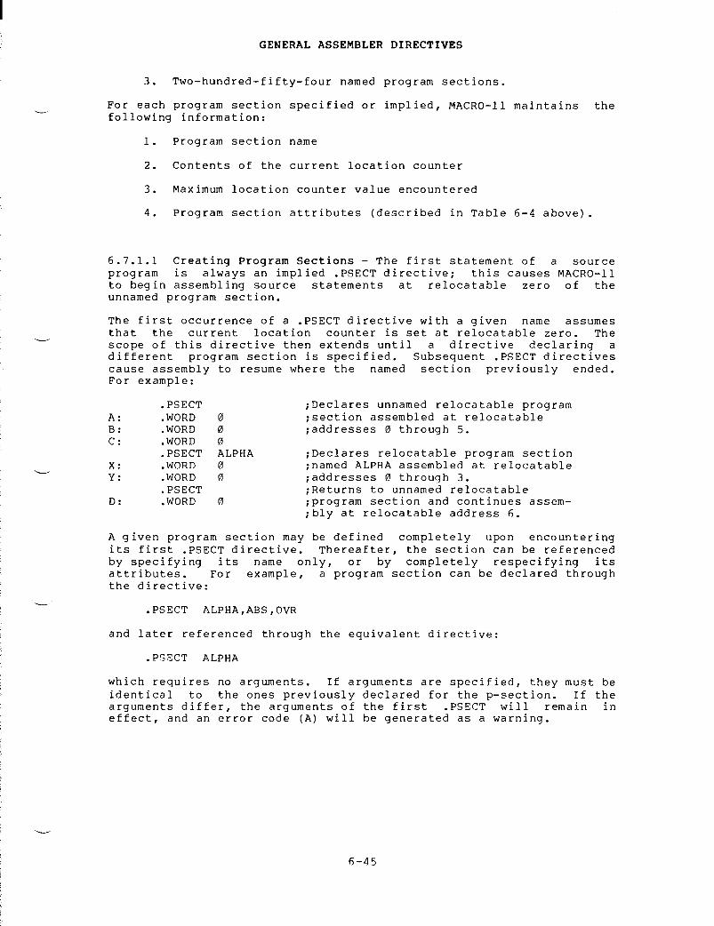
3 .
Two-hundred-fifty-four named program sections
.
For
each program section specified or implied, MACRO-11 maintains the
following
information
:
1 .
Program section name
GENERAL
ASSEMBLER DIRECTIVES
2 .
Contents of the current location counter
3 .
Maximum location counter value encountered
4 .
Program section attributes (described in Table 6-4 above)
.
6 .7 .1 .1
Creating Program Sections - The first statement of a source
program
is always an implied PSECT directive
;
this causes MACRO-11
to
begin assembling source statements at relocatable zero of the
unnamed
program section
.
The
first occurrence of a PSECT directive with a given name assumes
that
the current location counter is set at relocatable zero
.
The
scope
of this directive then extends until a directive declaring a
different
program section is specified
.
Subsequent PSECT directives
cause
assembly to resume where the named section previously ended
.For
example
:
bly
at relocatable address 6
.
A
given program section may be defined completely upon encountering
its
first PSECT directive
.
Thereafter, the section can be referenced
by
specifying its name only, or by completely respecifying its
attributes .
For example, a program section can be declared through
the
directive
:
.PSECT
ALPHA,ABS,OVR
and
later referenced through the equivalent directive
:
.PSECT
ALPHA
which
requires no arguments
.
If arguments are specified, they must be
identical
to the ones previously declared for the p-section
.
If the
arguments
differ, the arguments of the first PSECT will remain in
effect,
and an error code (A) will be generated as a warning
.
.PSECT ;Declares
unnamed relocatable program
A : WORD 0 ;section
assembled at relocatable
B : WORD 0 ;addresses
0 through 5
.C : WORD 0
.PSECT ALPHA ;Declares
relocatable program section
X : WORD 0 ;named
ALPHA assembled at relocatable
Y : WORD 0 ;addresses
0 through 3
..PSECT ;Returns
to unnamed relocatable
D : WORD 0 ;program
section and continues assem-
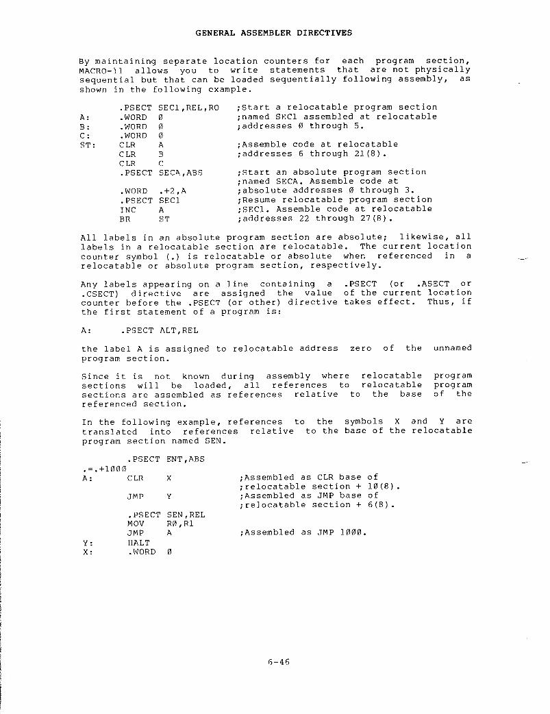
By maintaining separate location counters for each program section,MACRO-11 allows you to write statements that are not physicallysequential but that can be loaded sequentially following assembly, asshown in the following example .
All labels in an absolute program section are absolute ; likewise, alllabels in a relocatable section are relocatable . The current locationcounter symbol ( .) is relocatable or absolute when referenced in arelocatable or absolute program section, respectively .Any labels appearing on a line containing a
PSECT (or
ASECT or.CSECT) directive are assigned the value of the current locationcounter before the PSECT (or other) directive takes effect . Thus, ifthe first statement of a program is :A :
PSECT ALT,REL
GENERAL ASSEMBLER DIRECTIVES
the label A is assigned to relocatable address zero of the unnamedprogram section .Since it is not known during assembly where relocatable programsections will be loaded, all references to relocatable programsections are assembled as references relative to the base of thereferenced section .In the following example, references to the symbols X and Y aretranslated into references relative to the base of the relocatableprogram section named SEN .
.PSECT ENT,ABS.= .+1000A : CLR X ;Assembled as CLR base of;relocatable section + 10(8) .imp Y ;Assembled as JMP base of;relocatable section + 6(8) ..PSECT SEN,RELMOv R0,R1imp A ;Assembled as imp 1000 .Y : HALTX : WORD 0
.PSECT SEC1,REL,RO ;Start a relocatable program sectionA : WORD 0 ;named SEC1 assembled at relocatableB : WORD 0 ;addresses 0 through 5 .C : WORD 0ST : CLR A ;Assemble code at relocatableCLR B ;addresses 6 through 21(8) .CLR C.PSECT SECA,ABS ;Start an absolute program section;named SECA . Assemble code at.WORD .+2,A ;absolute addresses 0 through 3 ..PSECT SEC1 ;Resume relocatable program sectionINC A ;SEC1 . Assemble code at relocatableBR ST ;addresses 22 through 27(8) .

GENERAL
ASSEMBLER DIRECTIVES
NOTE
In
the preceding example, using a
constant
in conjunction with the current
location
counter symbol (
.)
in the form
.=1000
would result in an error, because
constants
are always absolute and are
always
associated with the program's
.ASECT
(
.
ABS
.) .
If the form
.=1000were
used, a program section
incompatibility
would be detected
.
See
Section
3
.6
for a dicussion of the
current
location counter
.
Thus,
MACRO-11 provides the linker or task builder with the necessary
information
to resolve the linkages between various program sections
.Such
information is not necessary, however, when referencing an
absolute
program section, because all instructions in an absolute
program
section are associated with an absolute virtual address
.
6 .7 .1 .2
Code or Data Sharing - Named relocatable program sections
with
the arguments GBL and OVR operate in the same manner as FORTRAN
COMMON,
that is, program sections of the same name with the arguments
GBL
and OVR from different assemblies are all loaded at the same
location
at link time
.
All other program sections (those with the
argument
CON) are concatenated
.
A
single symbol could name both an internal symbol and a program
section .
Considering FORTRAN again, using the same symbolic name is
necessary
to accommodate the following statement
:
COMMON
/X/ A,B,C,X
where
the symbol X represents the base of the program section and also
the
fourth element of that section
.
6 .7 .1 .3
Memory Allocation Considerations - The assembler does not
generate
an error when a module ends at an odd location
.
You can,
therefore,
place odd length data at the end of a module
.
However,
when
several modules contain object code contributions to the same
program
section having the concatenate attribute (see Table 6-4
;CON/OVR),
odd length modules (except the last) may cause succeeding
modules
to be linked starting at odd locations, thereby making the
linked
program unexecutable
.
To avoid this problem, separate code and
data
from each other and place them in separately named program
sections
(see Table 6-4
;
I/D)
.
The linker or task builder can then
begin
each program section on an even address
.
Refer to the
applicable
system manual for further information on memory allocation
of
tasks (see Section 0
.3
in the Preface)
.

Formats :
.ASECT
.CSECT
.CSECT
symbol
Note
that the statement
:
.CSECT
JIM
is
identical to the statement
:
.PSECT
JIM,GBL,OVR
GENERAL
ASSEMBLER DIRECTIVES
6 .7 .2
ASECT
and CSECT Directives
.ASECT
.CSECT
where :
symbol represents one or more of the arguments in Table 6-4
.
IAS
and RSX-11M assembly-language programs use the PSECT and
ASECTdirectives
exclusively, because the PSECT directive provides all the
capabilities
of the CSECT directive defined for other PDP-11
assemblers .
MACRO-11
will accept both ASECT and CSECT directives,
but
assembles them as though they were
PSECT
directives with the
default
attributes listed in Table 6-5
.
Compatibility exists between
other
MACRO-11 programs and the IAS/RSX-11M Task Builders, because the
Task
Builders also treat the ASECT and CSECT directives like PSECT
directives
with the default values listed in Table 6-5
.
Table
6-5
Program
Section Default Values
*
In RT-11 this program section has no default name
.
because
the CSECT default values GBL and OVR are assumed for the
named
program section
.
6-48
Attribute.ASECT
Default
Value
CSECT
(named)
CSECT
(unnamed)
Name .
ABS
. name .
BLK
.*
ACCESS RW RW RW
Type I I I
Scope GBL GBL LCL
Relocation ABS REL REL
Allocation OVR OVR CON

6 .7 .3
SAVE
Directive
Format :
6 .7 .4
RESTORE
Directive
Format :
.SAVE
.RESTORE
GENERAL
ASSEMBLER DIRECTIVES
.SAVE
stores the current program section context on the top
program
section context stack, while leaving the current
section
context in effect
.
If the stack is full when SAVE is
an
error (A) occurs
.
The stack can handle 16 SAVEs
.
The
section
context includes the values of the current location
and
the maximum value assigned to the location counter in the
program
section
.
See
Figure 6-7 for an example of SAVE
.
The
RESTORE directive retrieves the program section from the top of
the
program section context stack
.
If the stack is empty when
.RESTORE
is issued, an error (A) occurs
.
When RESTORE retrieves a
program
section, it restores the current location counter to the value
it
had when the program section was saved
.
See
Figure 6-7 for an example of RESTORE
.
.SAVE
to
the
programissued,programcountercurrent
.RESTORE

.MAIN . MACRO VO5 .00 Monday 17- .Jan-83 08 :52 Page J.EXAMPLE OF .SAVE/ .RESTORE USAGE
1
SBTTL Example of .SAVE/ .RESTORE usage23
;+4
; Macro DS5
; Define local impure storage6
;-78
MACRO DS
NAMEPSIZE9
SAVE
;Save the current PSECT10
PSECT IMPURErDyGBL
;Store the data in the impure PSECT11
NAME :
BLKW
SIZE
;Set aside the space12
RESTORE
;Reenter the current PSECT13
ENDM1415
Figure 6-7 Example of SAVE and RESTORE Directives
16171819
;+; SCANSY; Scan the hash;-
table for valid entries
2021 000000 016701 000000' SCANSY : MOV SYMBASPRI ;Get base of table22 000004 010167 000002' MOV RIYCURSYM ;Initialize Pointer to table23 000010 066701 000004' ADD SYMSIZYR1 ;Point Past the table24 000014 010167 000006' MOV RIYSYMTOP ;Save end address25 r26 ; Rest of routine . . .2728 000020 000207 RETURN ;Table is scannedt exit2930 ;+31 ; Local data32 ;-3334 000022 DS SYMBAS ;Base address of symbol table35 000022 DS CURSYM ;Current symbol Pointer during scan36 000022 DS SYMSIZ iSize of tablet bytes37 000022 DS SYMTOP ;Set to end address of table3639 ;+40 ; SSORT41 ; Perform shell sort on symbol table Prior to listing42 ;-4344 000022 016701 000006' SSORT : MOV SYMTOP .RI ;Get end of table4546 ; Additional code . . .4748 000001 END

6 .8
SYMBOL CONTROL DIRECTIVES
The
symbol control directives are used to set the type of a given
symbol .
6 .8 .1
GLOBL
Directive
Format :
.GLOBL
syml,sym2 . . . .
symn
GENERAL
ASSEMBLER DIRECTIVES
.GLOBL
where :
syml,
represent
legal symbolic names
.
When
multiple
sym2 . . . .
symbols
are specified, they are separated by any
symn
legal
separator (comma, space, and/or tab)
.
A
GLOBL directive may also embody a label field and/or a comment
field .
The
GLOBL directive is provided to define (and thus provide linkage
to)
symbols not otherwise defined as global symbols within a module
.In
defining global symbols the directive GLOBL A,B,C is similar to
:
A== :expression
A==expression A
: :B== :expression
or B==expression or B
: :C== :expression
C==expression C
: :
Because
object modules are linked by global symbols, these symbols are
vital
to a program
.
The following paragraph, describing the
processing
of a program from assembly to linking, explains the
global's
role
.
In
assembling a source program, MACRO-11 produces a relocatable object
module
and a listing file containing the assembly listing and symbol
table .
The linker or task builder joins separately assembled object
modules
into a single executable image
.
During linking, object
modules
are relocated relative to the base of the module and linked by
global
symbols
.
Because these symbols will be referenced by other
program
modules, they must be singled out as global symbols in the
defining
modules
.
As
shown above, the GLOBL directive, global
assignment
operator, or global label operator will define a symbol as
global .
All
internal symbols appearing within a given
program
must be defined
at
the end of assembly pass 1 or they will
be
assumed to be default
global
references
.
Refer to Section 6
.2 .1 for
a description of
enabling/disabling
of global references
.

In
the following example, A and B are entry-point symbols
.
The symbol
A
has been explicitly defined as a global symbol by means of the
.GLOBL
directive, and the symbol B has been explicitly defined as a
global
label by means of
.
the double colon (
: :) .
Since the symbol C is
not
defined as a label within the current assembly, it is an external
(global)
reference if ENABL GBL is in effect
.
GENERAL
ASSEMBLER DIRECTIVES
External
symbols can appear in the operand field of an instruction or
MACRO-11
directive as a direct reference, as shown in the examples
below :
CLR
EXT
.WORD
EXT
CLR
@EXT
External
symbols may also appear as a term within an expression, as
shown
below
:
CLR
EXT+A
.WORD
EXT-2
CLR
@EXT+A(R1)
An
undefined external symbol cannot be used in the evaluation of a
direct
assignment statement or as an argument in a conditional
assembly
directive (see Sections 3
.3,
6
.9 .1
and 6
.9 .3) .
6 .8 .2.
WEAK
Directive
Format :
where :
syml
sym2 . . . .symn
Example :
.WEAK
syml,sym2
. . . .
symn
.WEAK
represents
legal symbolic names
.
When multiple
symbols
are specified, they are separated by any
legal
separator (comma, space, and/or tab)
.
SUB1,SUB2
The
WEAK directive may also embody a label field and/or
field .
6-52
.WEAK
a comment
Define
a subroutine with
external
subroutine
2
entry points which calls an
.PSECT ;Declare
the unnamed program section
..GLOBL
A
;Define
A as a global symbol
.A : MOV
@(R5)+,RH
;Define
entry point A
.MOV
#X,R1
X : JSR
PC,C
;Call
external subroutine C
.RTS
R5
;Exit .B : : MOV
(R5)+,Rl
;Define
entry point B
.CLR
R2
BR
X

The WEAK directive is used to specify symbols that are either definedexternally in another module or defined globally in the currentmodule . This directive suppresses object library searches forspecified external symbols .When the WEAK directive specifies a symbol that is externallydefined, it is considered a global symbol . If the linker finds thesymbol's definition in another module, it uses that definition . Ifthe linker does not find an external definition, the symbol is given avalue of 0 . The linker does not search a library for the globalsymbol, but if a module brought in from a library for another reasoncontains the symbol's definition, the linker uses that definition .If a symbol that is defined in the current module is specified by the.WEAK directive, the symbol is considered globally defined . However,if the current module is inserted in an object library, the symbol isnot inserted in the library's symbol table . Consequently, the moduleis not found when the library is searched at link time to resolve thesymbol .
6 .9 CONDITIONAL ASSEMBLY DIRECTIVESConditional assembly directives allow you to include or exclude blocksof source code during the assembly process, based on the evaluation ofstated condition tests within the body of the program .
6 .9 .1 Conditional Assembly Block DirectivesFormat :
GENERAL ASSEMBLER DIRECTIVES
NOTEThe WEAK directive is only supported bythe RT-11 V5 .0 LIBRARIAN (LIBR) andLINKER (LINK) . Support is not yetimplemented in the RSX-11 taskbuilder(TKB) or librarian (LBR) .
AFJ .ENDCJ
.IF cond,argument(s) ;Start conditional assembly block .range ;Range of conditional assembly block ..ENDC ;End of conditional assembly block .

where :
cond
represents
a specified condition that must be
met
if the block is to be included in the
assembly .
The conditions that may be tested by
the
conditional assembly directives are defined
in
Table 6-6
.
argument(s)
represent(s) the symbolic argument(s) or
expression(s)
of the specified conditional test
.These
arguments are thus a function of the
condition
to be tested (see Table 6-6)
.
range
represents
the body of code that is either
included
in the assembly, or excluded, depending
upon
whether the condition is met
.
.ENDC
terminates
the conditional assembly block
.
This
directive
must be present to end the conditional
assembly
block
.
A
condition test other than those listed in Table 6-6, an illegal
argument,
or a null argument specified in an IF directive causes that
line
to be flagged with an error code (A) in the assembly listing
.
Table
6-6
Legal
Condition Tests for Conditional Assembly Directives
Conditions
GENERAL
ASSEMBLER DIRECTIVES
represents
any legal separator (comma, space,
and/or
tab)
.
Arguments
Assemble
Block If
:
Expression
Expression
is equal to 0
(or
not equal to 0)
.
Expression
Expression is greater
than
0 (or less than or
equal
to 0)
.
Expression
Expression
is less than 0
(or
greater than or equal
to
0)
.
Symbolic
Symbol
is defined (or not
argument
defined)
.
Macro-type
Argument
is blank (or
argument
non-blank)
.
(continued
on next page)
Positive Complement
EQ NE
GT LE
LT GE
DF NDF
B NB

Table
6-6 (Cont
.)Legal
Condition Tests for Conditional Assembly Directives
Conditions
Positive
Complement Arguments
IDN
DIF
Two
macro-type
arguments
An
example of a conditional assembly directive follows
:
.IF
EQ ALPHA+1
;Assemble
block if ALPHA+1=0
.ENDC
The
two operators & and ! have special meaning
conditions,
in that they are allowed in grouping
&
Logical
AND operator
!
Logical
inclusive OR operator
For
example, the conditional assembly statement
:
.IF
DF SYM1 & SYM2
.ENDC
GENERAL
ASSEMBLER DIRECTIVES
A
macro-type argument (which is a form
of
symbolic argument), as shown below,
is
enclosed within angle brackets or
denoted
with an up-arrow construction
(as
described in Section 7
.3) .
<A,B,C>"/124/
NOTE
results
in the assembly of the conditional block if the
and
SYM2 are both defined
.
Assemble
Block If
:
Arguments
are identical
(or
different)
.
The IF
IDN/ .IF
DIF conditional
directives
are not
alphabetically
case
sensitive
by default
.The
user may enable these
directives
to be case
sensitive
by using the
.ENABL
option (
.ENABLLCM) .
withinsymbolic
DF
and NDF
arguments .
symbols
SYM1

GENERAL ASSEMBLER DIRECTIVESNested conditional directives take the form :
Conditional Assembly DirectiveConditional Assembly Directive. ENDC. ENDC
For example, the following conditional directives :.IF DF SYM1.IF DF SYM2. ENDC. ENDC
can govern whether assembly is to occur . In the example above, if theoutermost condition is unsatisfied, no deeper level of evaluation ofnested conditional statements within the program occurs .Each conditional assembly block must be terminated with an
ENDCdirective .
An
ENDC directive encountered outside a conditional_assembly block is flagged with an error code (0) in the assemblylisting .MACRO-11 permits a nesting depth of 16(10) conditional assemblylevels . Any statement that attempts to exceed this nesting leveldepth is flagged with an error code (0) in the assembly listing .
.OFF
6 .9 .2 Subconditional Assembly Block DirectivesAFTFT.IFTF
Formats :IFFIFT.IFTF
Subconditional directives may be placed within conditional assemblyblocks to indicate :1 . The assembly of an alternate body of code when the conditionof the block tests false .2 . The assembly of a non-contiguous body of code within theconditional assembly block, depending upon the result of theconditional test in entering the block .3 . The unconditional assembly of a body of code within aconditional assembly block .
b-5b

The
subconditional directives are described in detail in Table 6-7
.If
a subconditional directive appears outside a conditional assembly
block,
an error code (0) is generated in the assembly listing
.
SubconditionalDirective
.IFF
.IFT
.IFTF
GENERAL
ASSEMBLER DIRECTIVES
Table
6-7
Subconditional
Assembly Block Directives
Function
If
the condition tested upon entering the
conditional
assembly block is false, the code
following
this directive, and continuing up to the
next
occurrence of a subconditional directive or to
the
end of the conditional assembly block, is to be
included
in the program
.
If
the condition tested upon entering the
conditional
assembly block is true, the code
following
this directive, and continuing up to the
next
occurrence of a subconditional directive or to
the
end of the conditional assembly block, is to be
included
in the program
.
The
code following this directive, and continuing up
to
the next occurrence of a subconditional directive
or
to the end of the conditional assembly block, is
to
be included in the program, regardless of the
result
of the condition tested upon entering the
conditional
assembly block
.
The
implied argument of a subconditional directive is the condition
test
specified upon entering the conditional assembly block, as
reflected
by the initial directive in the conditional coding examples
below .
Conditional or subconditional directives in nested conditional
assembly
blocks are not evaluated if the previous (or outer) condition
in
the block is not satisfied
.
Examples 3 and 4 below illustrate
nested
directives that are not evaluated because of previous
unsatisfied
conditional coding
.
EXAMPLE
1
:
Assume that symbol SYM is defined
.
.IF
DF SYM
;Tests
TRUE, SYM is defined
.
Assemble
;the
following code
.
.IFF ;Tests
FALSE
.
SYM is defined
.
Do not
;assemble
the following code
.
.IFT ;Tests
TRUE
.
SYM is defined
.
Assem-
;ble
the following code
.
.IFTF ;Assemble
following code uncondition-
;ally .

.IFT
;Tests
TRUE
.
SYM is defined
.
Assem-
;ble
remainder of conditional assem-
;bly
block
.
.
ENDC
EXAMPLE
2
:
Assume that symbol X is defined and that symbol Y is not
defined .
.IF
DF X
;Tests
TRUE, symbol X is defined
..IF
DF Y
;Tests
FALSE, symbol Y is not defined
..IFF
;Tests
TRUE, symbol Y is not defined,
;assemble
the following code
.
.IFT
;Tests
FALSE, symbol Y is not defined
.;Do
not assemble the following code
.
.
ENDC
ENDC
EXAMPLE
3
:
Assume that symbol A is defined and that symbol B is not
defined .
.IF
DF A
;Tests
TRUE
.
A is defined
.;Assemble
the following code
.MOV
A,AR1
GENERAL
ASSEMBLER DIRECTIVES
IFF
;Tests
FALSE
.
A is defined
.
Do not
;assemble
the following code
.MOV
R1,RO
.IF
NDF B
;Nested
conditional directive is not
;evaluated .
.
ENDC
ENDC
6- 5 8
.
ENDC
.
ENDC
EXAMPLE
4
: Assume
that
defined .symbol
X is not defined and that symbol Y is
.IF
DF
X ;Tests
FALSE
.
Symbol X is not defined
.;Do
not assemble the following code
..IF
DF
Y ;Nested
conditional directive is not
;evaluated .
.IFF ;Nested
subconditional directive is
;not
evaluated
.
.IFT ;Nested
subconditional directive is
;not
evaluated
.

6 .9 .3 Immediate Conditional Assembly DirectiveFormat :
.IIF cond,arg,statementwhere : cond
represents one of the legal condition tests definedfor conditional assembly blocks in Table 6-6 .
GENERAL ASSEMBLER DIRECTIVES
.IIF
represents any legal separator (comma, space,and/or tab) .arg
represents the argument associated with theimmediate conditional directive ;
an expression,symbolic argument, or macro-type argument, asdescribed in Table 6-6 .represents the separator between the conditionalargument and the statement field . If the precedingargument is an expression, then a comma must beused ; otherwise, a comma, space and/or tab may beused .
statement represents the specified statement to be assembledif the condition is satisfied .An immediate conditional assembly directive provides a means forwriting a 1-line conditional assembly block . The use of thisdirective requires no terminating ENDC statement and the condition tobe tested is completely expressed within the line containing thedirective .For example, the immediate conditional statement :
.IIF
DF FOO,BEQ ALPHAgenerates the code
BEQ ALPHAif the symbol FOO is defined within the source program .As with the IF directive, a condition test other than those listed inTable 6-6, an illegal argument, or a null argument specified in an.IIF directive results in an error code (A) in the assembly listing .

6 .10
FILE CONTROL DIRECTIVES
The
MACRO-11 file control directives are used to add file names to
macro
library lists and to insert a source file into the source file
being
currently used
.
6 .10 .1
LIBRARY
Directive
Format :
where :
.LIBRARY
string
GENERAL
ASSEMBLER DIRECTIVES
string
represents
a delimited string that is the file
specification
of a macro library
.
The
LIBRARY directive adds a file name to a macro library list that
is
searched whenever a MCALL or an
within
a MACRO-11 program
.
The
are
searched in the reverse order in
assembler .
is
searched
.
A library list
undefined
opcode is encountered
libraries
that make up the list
which
they were specified to the MACRO-11
If
any information was omitted from the macro
default
values are assumed
.
The default file
MACRO-11/RT-11
is DK
: .MLB,
and for other systems it
The
LIBRARY directive is used as follows
:
.LIBRARY
/DB1
:[SMITH]USERLIB/.LIBRARY
?DK
:SYSDEF .MLB?.LIBRARY
\CURRENT
.MLB\
NOTE
If
you are using MACRO-11 with an RT-11
operating
system, you should be aware of
the
following two restrictions
.
The
device
driver for the specified device
that
the LIBRARY file resides on must
already
be loaded, either explicitly
with
the KMON LOAD command, or
implicitly
by reference to the device on
the
original MACRO-11 command line
.
The
second
restriction is that there is a
limit
on the number of
LIBRARY
files
that
may be specified
.
The
limit is
twelve
minus the number of files
specified
in the MACRO-11 command line
.Since
there can be a maximum of eight
files
on a MACRO-11/RT-11 command line,
there
are at least four available slots
for
LIBRARY files
.
6- 6 0
LIBRARY
library
argument,
specification
for
is
SY
: .MLB .
inMACRO-11
searches all macro libraries if it finds an unknown symbol
the
opcode field and the auto-mcall option has been previously enabled
by
ENABL MCL
.

6 .10 .2
INCLUDE
Directive
Format :
.INCLUDE
string
GENERAL
ASSEMBLER DIRECTIVES
where :
string
represents
a delimited string that is the file
specification
of a macro source file
.
The
INCLUDE directive is used to insert a source file within the
source
file currently being used
.
When this directive is encountered,
the
current source file is stacked and the source file specified by
the
directive is read into memory
.
When the end of the specified
source
file is reached, the original source file is popped from the
stack
and assembly resumes at the line following the directive
.
A
source
file can also be inserted within a source file that has already
been
specified by the INCLUDE directive
.
In this case the original
source
file and the first source file specified by the INCLUDE
directive
are stacked and the second specified source file is read
into
memory
.
When the end of the second source file is reached, the
first
specified source file is popped from the stack and assembly
resumes
at the line following the directive, and when the end of the
first
specified source file is reached, the original source file is
popped
from the stack and assembly of that file is started again at
the
line following the INCLUDE directive
.
The
maximum nesting level
of
source files specified by the INCLUDE directive is five
.
If
any information is omitted from the source file argument, default
values
are assumed
.
The default file specification for MACRO-11/RT-11
is
DK
: .MAC,
and for other systems it is SY
: .MAC .
The
INCLUDE directive is used as follows
:
.INCLUDE
/DR3 :[1,2]MACROS/
;File
MACROS
.MAC.INCLUDE
?DK
:SYSDEF?.INCLUDE
\CURRENT
.MAC\
NOTE
If
you are using MACRO-11 with an RT-11
operating
system, the device driver for
the
specified device that the INCLUDE
file
resides on must already be loaded,
either
explicitly with the KMON LOAD
command,
or implicitly by reference to
the
device on the original MACRO-11
command
line
.
INCLUDE


7 .1
DEFINING MACROS
CHAPTER
7
MACRO
DIRECTIVES
By
using macros a programmer can use a single line to insert a
sequence
of lines into a source program
.
A
macro definition is headed by a MACRO directive (see Section 7
.1 .1)followed
by the source lines
.
The source lines may optionally contain
dummy
arguments
.
If such arguments are used, each one is listed in
the
MACRO directive
.
A
macro call (see Section 7
.3)
is the statement used by the programmer
to
call the macro into the source program
.
It consists of the macro
name
followed by the real arguments needed to replace any dummy
arguments
used in the macro
.
Macromaindummy
expansion
is the insertion of the macro source lines into the
program .
Included in this insertion is the replacement of the
arguments
by the real arguments
.
directives
provide the means to manipulate the macro expansions
.per
source line
.
Each directive may
or
more operands
.
Legal
operands
The
macros and their associated
Macroonly
one directive is allowed
have
a blank operand field or one
differ
with each directive
.directives
are detailed in this chapter
.
7 .1 .1
MACRO
Directive
Format :
[label :]
MACRO
where :
label
represents
an
name
represents
any
and/or
tab)
.
name,
dummy argument list
optional
statement label
.
represents
the user-assigned symbolic name
macro .
This name may be any legal symbol
be
used as a label elsewhere in the program
.
legal
.MACRO
of
the
and
may
separator
(comma, space,

where :
dummy
represents
a number of legal symbols (see Section
argument
3
.2 .2)
that may appear anywhere in the body of the
list
macro
definition, even as a label
.
These
dummy
symbols
can be used elsewhere in the program with
no
conflict of definition
.
Multiple dummy
arguments
specified in this directive may be
separated
by any legal separator
.
The detection
of
a duplicate or an illegal symbol in a dummy
argument
list terminates the scan and causes an
error
code (A) to be generated
.
A
comment may follow the dummy argument list in a MACRO directive, as
shown
below
:
The
first statement of a macro definition must be a MACRO directive
.
7 .1-.2
ENDM
Directive
Format :
where :
name
represents
an optional argument specifying the
name
of the macro being terminated by the
directive .
Example :
MACRO
DIRECTIVES
.MACRO
ABS A,B
;Defines
macro ABS with two arguments
.
.ENDM
[name]
NOTE
because
invalid labels or labels
constructed
with the concatenation
character
will cause the macro directive
to
be ignored
.
This may result in
improper
termination of the macro
definition .
This
NOTE also applies to
IRP,
IRPC,and
REPT
.
.ENDM
;Terminates
the current
;macro
definition
.
.ENDM
ABS
;Terminates
the current
;macro
definition named ABS
.
.ENDM
Although it is
legal for a label to
appear on a
MACRO directive, this
practice is discouraged,
especially in
the
case
of
nested macro definitions,

If
specified, the macro name in the
name
specified in the corresponding
statement
is flagged with
In
either case, the
Specifying
the macro name
to
detect missing ENDM
definitions .
The
ENDM directive must not have a
attached,
it will be ignored
.
If
directive
will be ignored
.
The
ENDM directive may be followed
below :
The
final statement of every macro definition must be an
directive .
The ENDM directive is also used to terminate indefinite
repeat
blocks (see Section 7
.6)
and may be used to terminate repeat
blocks
(see Section 7
.7) .
7 .1 .3
MEXIT
Directive
Format :
.MACRO
TYPMSG MESSGE
JSR
R5,TYPMSG
.WORD
MESSGE
.ENDM
;End
.MEXIT
The
MEXIT directive may be used to terminate a macro expansion before
the
end of the macro is encountered
.
This directive is also legal
within
repeat blocks (see Sections 7
.6
and 7
.7) .
It is most useful in
nested
macros
.
The
MEXIT directive terminates the current macro as
though
an ENDM directive had been encountered
.
Using
the
MEXITdirective
bypasses the complexities of nested conditional directives
and
alternate assembly paths, as shown in the following example
:
MACRO
DIRECTIVES
ENDM
statement must match the
.MACRO
directive
.
Otherwise, the
an
error code (A) in the assembly listing
.current
macro definition is
terminated .i n
the ENDM statement thus permits MACRO-11
statements
or improperly nested macro
;Type
a message
.
of
TYPMSG macro
.
7- 3
label .
If a legal label is
an
illegal label is attached, the
by
a comment field, as shown
.ENDM
.MEXIT
In
an assembly where the dummy symbol N is replaced by zero (see Table
6-6),
the
MEXIT
directive would assemble the conditional block and
terminate
the macro expansion
.
When
macros are nested, a
MEXITdirective
causes an exit to the next higher level of macro expansion
.
.MACRO
ALTR N,A,B
.IF"EQ
N
;Start
conditional assembly block
.
.MEXIT ;Terminate
macro expansion
..ENDC ;End
conditional assembly block
.
.ENDM ;Normal
end of macro
.

A
MEXIT directive encountered outside a macro definition is flagged
with
an error code (0) in the assembly listing
.
7 .1 .4
MACRO Definition Formatting
MACRO
DIRECTIVES
A
form-feed character used within a macro definition causes a page
eject
during the assembly of the macro definition
.
A page eject,
however,
is not performed when the macro is expanded
.
Conversely,
when the PAGE directive is used in a macro definition, it
is
ignored during the assembly of the macro definition, but a page
eject
is performed when that macro is expanded
.
7 .2
CALLING MACROS
Format :
[label :]
name
real
arguments
where :
label
represents
an optional statement label
.
name
represents
the name of the macro, as specified in
the
MACRO directive (see Section 7
.1 .1) .
real
represent
symbolic arguments which replace the
arguments
dummy
arguments listed in the
MACRO
directive
.When
multiple arguments occur, they are separated
by
any legal separator
.
Arguments to the macro
call
are treated as character strings, their usage
is
determined by the macro definition
.
A
macro definition must be established by means of the
MACROdirective
(see Section 7
.1 .1)
before the macro can be called and
expanded
within the source program
.
When
a macro name is the same as a user label, the appearance of the
symbol
in the operator field designates the symbol as a macro call
;the
appearance of the symbol in the operand field designates it as a
label,
as shown below
:
ABS :
7 .3
ARGUMENTS IN MACRO DEFINITIONS AND MACRO CALLS
Multiple
arguments within a macro definition or macro call must be
separated
by one of the legal separating characters described in
Section
3
.1 .1 .
7- 4
MOV (RO),Rl ;ABS
is defined as a label
.
BR ABS ;ABS
is considered to be a label
.
ABS #4,ENT,LAR ;ABS
is a macro call
.

Macro
definition arguments (dummy) and macro call arguments (real)
normally
maintain a strict positional relationship
.
That is, the
first
real argument in a macro call corresponds with the first dummy
argument
in a macro definition
.
Only the use of keyword arguments in
a
macro call can override this correspondence (see Section 7
.3 .5) .
For
example, the following macro definition and its associated macro
call
contain multiple arguments
:
.MACRO
REN A,B,C
REN
ALPHA,BETA,<C1,C2>
MACRO
DIRECTIVES
Arguments
which themselves contain separating characters must be
enclosed
in paired angle brackets
.
For example, the macro call
:
REN
<MOV X,Y>,#44,WEV
causes
the entire expression
MOV
X,Y
to
replace all occurrences of the symbol A in the macro definition
.Real
arguments within a macro call are considered to be character
strings
and are treated as a single entity during the macro expansion
.
The
up-arrow (") construction allows angle brackets to be passed as
part
of the argument
.
This construction, for example, could have been
used
in the above macro call, as follows
:
REN
"/<MOV
X,Y>/,#44,WEV
causing
the entire character string <MOV X,Y> to be passed as an
argument .
Because
of the use of the up-arrow (") shown above, care must be taken
when
passing an argument beginning with a unary operator ("0, "D, "B,
"R,
"F
. . .
)
.
These arguments must be enclosed in angle brackets (as
shown
below) or MACRO-11 will read the character following the
up-arrow
as a delimiter
.
REN
<"0 411>,X,Y
The
following macro call
:
REN
#44,WEV"/MOV
X,Y/
contains
only two arguments (#44 and WEV"/MOV X,Y/), because the
up-arrow
is a unary operator (see Section 3
.1 .3)
and it is not
preceded
by an argument separator
.
As
shown in the examples above, spaces can be used within bracketed
argument
constructions to increase the legibility of such expressions
.

7 .3 .1
Macro Nesting
Macro
nesting occurs where the expansion of one macro includes a call
to
another
.
The depth of nesting allowed depends upon the amount of
dynamic
memory used by the source program being assembled
.
To
pass an argument containing legal argument delimiters to nested
macros,
enclose the argument in the macro definition within angle
brackets,
as shown in the coding sequence below
.
This extra set of
angle
brackets for each level of nesting is required in the macro
definition,
not in the macro call
.
.MACRO
LEVELI DUM1,DUM2
LEVEL2
<DUM1>
LEVEL2
<DUM2>
.ENDM
.MACRO
LEVEL2 DUM3
DUM3ADD
#10,40
MOV
RO,(R1)+
.ENDM
MACRO
DIRECTIVES
A
call to the LEVELI macro, as shown below, for example
:
LEVELI
<MOV X,RO>,<MOV R2,RO>
causes
the following macro expansion to occur
:
MOV
X,RO
ADD
#10,RO
MOV
RO,(Rl)+
MOV
R2,RO
ADD
#10,RO
MOV
RO,(R1)+
When
macro definitions are nested, the inner definition cannot be
called
until the outer macro has been called and expanded
.
For
example,
in the following coding
:
.MACRO
LV1 A,B
.MACRO
LV2 C
ENDMENDM
the
LV2 macro cannot be called and expanded until the LV1 macro has
been
expanded
.
Likewise, any macro defined within the LV2 macro
definition
cannot be called and expanded until LV2 has also been
expanded .

7 .3 .2
Special Characters in Macro Arguments
If
an argument does not contain spaces, tabs, semicolons, or commas it
may
include special characters without enclosing them in a bracketed
construction .
For example
:
.MACRO
PUSH ARG
MOV
ARG,-(SP)
.ENDM
PUSH
X+3(%2)
causes
the following code to be generated
:
MOV
X+3
(%2) ,-(SP)
7 .3 .3
Passing Numeric Arguments as Symbols
If
the unary operator backslash (\) precedes an argument, the macro
treats
that argument as a numeric value in the current program radix
.The
ASCII characters representing this value are inserted in the macro
expansion,
and their function is defined in the context of the
resulting
code, as shown in the following example
:
The
above macro call (INC) would thus expand to
:
X0 : .WORD
4
In
this expanded code, the label X0
:
results from the concatenation
of
two real arguments
.
The single quote (') character in the label
A'B :
concatenates the real arguments X and 0 as they are passed
during
the expansion of the macro
.
This type of argument construction
is
described in more detail in Section 7
.3 .7 .
A
subsequent call to the same macro would generate the following code
:
X1 :
WORD 4
MACRO
DIRECTIVES
and
so on, for later calls
.
The two macro definitions are necessary
because
the symbol associated with dummy argument B (that is, C)
cannot
be updated in the CON macro definition, because the character 0
has
replaced C in the argument string (INC X, C)
.
In the CON macro
definition,
the number passed is treated as a string argument
.
(Where
the
value of the real argument is 0, only a single 0 character is
passed
to the macro expansion
.)
7-7
.MACRO INC
A,B
CON A,\B ;B
is treated as a number in current
B=B+1 ;program
radix
..ENDM.MACRO CON
A,B
A'B : WORD 4 ;A'B
is described in Section 7
.3 .7 ..ENDM
C=0 INC X,C

MACRO
DIRECTIVES
Passing
numeric values in this manner is useful in identifying source
listings .
For example, versions of programs created through
conditional
assemblies of a single source program can be identified
through
such coding as that shown below
.
Assume, for example, that
the
symbol ID in the macro call (IDT) has been equated elsewhere in
the
source program to the value 6
.
.MACRO
IDT SYM
;Assume
that the symbol ID takes
.IDENT
/V01
.'SYM/
;on
a unique 2-digit value
..ENDM
;Where
V01 is the update
;version
of the program
.
IDT.
\ID
The
above macro call would then expand to
:
.IDENT
/V01
.6/
where
6 is the numeric value of the symbol ID
.
7 .3 .4
Number of Arguments in Macro Calls
A
macro can be defined with or without arguments
.
If more arguments
appear
in the macro call than in the macro definition, an error code
(Q)
is generated in the assembly listing
.
If fewer arguments appear
in
the macro call than in the macro definition, missing arguments are
assumed
to be null values
.
The conditional directives IF B and IF
NB
(see Table 6-6) can be used within the macro to detect missing
arguments .
The number of arguments can also be determined using the
.NARG
directive (Section 7
.4 .1) .
7 .3 .5
Creating Local Symbols Automatically
A
label is often required in an expanded macro
.
In the conventional
macro
facilities thus far described, a label must be explicitly
specified
as an argument with each macro call
.
The user must be
careful
in issuing subsequent calls to the same macro in order to
avoid
duplicating labels
.
This concern can be eliminated through a
feature
of MACRO-11 that creates a unique symbol where a label is
required
in an expanded macro
.
As
noted in Section 3
.5,
MACRO-11 can automatically create local
symbols
of the form n$, where n is a decimal integer within the range
30000
through 65535, inclusive
.
Such local symbols are created by
MACRO-11
in numerical order, as shown below
:
30000$30001$
65534$65535$

This
automatic generation is invoked on each call of a macro whose
definition
contains a dummy argument preceded by the question mark (?)
character,
as shown in the macro definition below
:
B :
30000$ :
.MACRO
ALPHA, A,?B
;Contains
dummy argument B preceded by
;question
mark
.TST
A
BEQ
B
ADD
#5,A
.ENDM
MACRO
DIRECTIVES
A
local symbol is created automatically by MACRO-11 only when a real
argument
of the macro call is either null or missing, as shown in
Example
1 below
.
If the real argument is specified in the macro call,
however,
MACRO-11 inhibits the generation of a local symbol and normal
argument
replacement occurs, as shown in Example 2 below
.
(Examples 1
and
2 are both expansions of the Alpha macro defined above
.)
EXAMPLE
1
:
Create a Local Symbol for the Missing Argument
:
ALPHA
R1
;Second
argument is missing
.TST
Rl
BEQ
30000$
;Local
symbol is created
.ADD
#5,R1
EXAMPLE
2
:
Do Not Create a Local Symbol
:
XYZ :
ALPHA
R2,XYZ
;Second
argument XYZ is specified
.TST
R2
BEQ
XYZ
;Normal
argument replacement occurs
.ADD
#5,R2
Automatically
created local symbols are restricted to the first 16(10)
arguments
of a macro definition
.
Automatically
created local symbols resulting from the expansion of a
macro,
as described above, do not establish a local symbol block in
their
own right
.
When
a macro has several arguments earmarked for automatic local
symbol
generation, substituting a specific label for one such argument
risks
assembly errors because MACRO-11 constructs its argument
substitution
list at the point of macro invocation
.
Therefore, the
appearance
of a label, the ENABL LSB directive, or the PSECT
directive,
in the macro expansion will create a new local symbol
block .
The new local symbol block could leave local symbol references
in
the previous block and their symbol definitions in the new one,
causing
error codes in the assembly listing
.
Furthermore,
a later
macro
expansion that creates local symbols in the new block may
duplicate
one of the symbols in question, causing an additional error
code
(P) in the assembly listing
.

MACRO
DIRECTIVES
7 .3 .6
Keyword Arguments
Format :
name=string
where :
name
represents
the dummy argument,
string
represents
the real symbolic argument
.
The
keyword argument may not contain embedded argument separators
unless
delimited as described in Section 7
.3 .
Macros
may be defined with, and/or called with, keyword arguments
.When
a keyword argument appears in the dummy argument list of a macro
definition,
the specified string becomes the default real argument at
macro
call
.
When a keyword argument appears in the real argument list
of
a macro call, however, the specified string becomes the real
argument
for the dummy argument that matches the specified name,
whether
or not the dummy argument was defined with a keyword
.
If a
match
fails, the entire argument specification is treated as the next
positional
real argument
.
A
keyword argument may be specified anywhere in the dummy argument
list
of a macro definition and is part of the positional ordering of
argument .
A keyword argument may also be specified anywhere in the
real
argument list of a macro call but, in this case, does not affect
the
positional ordering of the arguments
.
1415
;
Now invoke
;several
times
1617 000000 TEST A,B,C
000000 0000000 WORD A000002 000000G WORD B000004 000000G WORD C
1819 000006 TEST ADDRES=20,BLOCK=30,CONTRL=40
000006 000040 WORD 40000010 000030 WORD 30000012 000020 WORD 20
2021 000014 TEST BLOCK=5
000014 000001 WORD 1000016 000005 WORD 5000020 000000G WORD TEMP
1 .LIST
ME
2 ;3 ;
Define a macro having keywords in dummy argument
4 ;
list
56 MACRO
TEST CONTRL=1,BLOCK,ADDRES=TEMP
7 WORD
CONTRL
8 WORD
BLOCK
9 WORD
ADDRES
10 .
ENDM
111213 ;

MACRO
DIRECTIVES
7 .3 .7
Concatenation of Macro Arguments
The
apostrophe or single quote character (') operates as a legal
delimiting
character in macro definitions
.
A single quote that
precedes
and/or follows a dummy argument in a macro definition is
removed,
and the substitution of the real argument occurs at that
point .
For example, in the following statements
:
.MACRO
DEF A,B,C,
A'B :
ASCIZ /C/
.BYTE
"A,''B
.ENDM
when
the macro DEF is called through the statement
:
DEF
X,Y,<MACRO-11>
it
is expanded, as follows
:
XY :
ASCIZ
/MACRO-11/
.BYTE
'X,'Y
In
expanding the first line, the scan for the first argument
terminates
upon finding the first apostrophe (') character
.
Since A
is
a dummy argument, the apostrophe (') is removed
.
The scan then
resumes
with B
;
B is also noted as another dummy argument
.
The two
real
arguments X and Y are then concatenated to form the label XY
: .The
third dummy argument is noted in the operand field of the ASCIZ
directive,
causing the real argument MACRO-11 to be substituted in
this
field
.
2223 000022 TEST CONTRL=5,ADDRES=VARIAB
000022 000005 WORD 5000024 000000 WORD000026 000000G WORD VARIAB
2425 000030 TEST
000030 000001 WORD 1000032 000000 WORD000034 000000G WORD TEMP
2627 000036 TEST ADDRES=JACK!JILL
000036 000001 WORD 1000040 000000 WORD000042 000000C WORD JACK!JILL
282930 000001 END

When
evaluating the arguments of the BYTE directive during expansion
of
the second line, the scan begins with the first apostrophe (')
character .
Since it is neither preceded nor followed by a dummy
argument,
this apostrophe remains in the macro expansion
.
The scan
then
encounters the second apostrophe, which is followed by a dummy
argument
and is therefore discarded
.
The scan of argument A is
terminated
upon encountering the comma (,)
.
The third apostrophe is
neither
preceded nor followed by a dummy argument and again remains in
the
macro expansion
.
The fourth (and last) apostrophe is followed by
another
dummy argument and is likewise discarded
.
(Four apostrophe
(')
characters were necessary in the macro definition to generate two
apostrophe
(') characters in the macro expansion
.)
7 .4
MACRO ATTRIBUTE DIRECTIVES
:
NARG,
NCHR, AND NTYPE
MACRO-11
has three directives that allow the user to determine certain
attributes
of macro arguments
:
NARG, NCHR, and NTYPE
.
The use of
these
directives permits selective modifications of a macro expansion,
depending
on the nature of the arguments being passed
.
These
directives
are described below
.
7 .4 .1
NARG
Directive
Format :
(label :]
where :
label
symbol
The
NARG directive
arguments
in the
.NARG
directive can
appears
elsewhere,
listing .
.NARG
symbol
MACRO
DIRECTIVES
represents
an optional statement label
.
.NARG
represents
any legal symbol
.
This symbol is
equated
to the number of non-keyword arguments in
the
macro call currently being expanded
.
If a
symbol
is not specified, the NARG directive is
flagged
with an error code (A) in the assembly
listing .
is
used to determine the number of non-keyword
macro
call currently being expanded
.
Hence, the
appear
only within a macro definition
;
if
it
an
error code (0) is generated in the assembly
An
example of the NARG directive is shown in Figure 7-1
.

7 .4 .2
NCHR
Directive
Format :
MACRO
DIRECTIVES
1
TITLE
NARG
23
ENABL
_LC
4
LIST
ME
s
:+
Figure
7-1 Example of NARG Directive
[label :]
NCHR
symbol,<string>
where :
.NCHR
represents
any legal separator (comma, space,
and/or
tab)
.
7- 1 3
67
1
Example
3-of
the
NARG
directive
89 MACRO NULL NUM
10 NARG SYM11 IF
ED
SYM12 MEXIT13 IFF14 REPT NUM15 MOP16 ENDM17 ENDC18 ENDM1920 000000 NULL
000000 NARG SYM.IF
ED
SYM.MEXIT.IFF.REPTNOP.ENDMENDC
2122 000000 NULL 6
000001 NARG SYM.IF
ED
SYM.MEXIT.IFF
000006 REPT 6NOP.ENDM
000000 000240 NOP000002 000240 NOP000004 000240 NOP000006 000240 NOP000010 000240 NOP000012 000240 NOP
.ENDC2324 000001 END
label represents
an optional statement label
.
symbol represents
any legal symbol
.
This symbol is
equated
to the number of characters in the
specified
character string
.
If a symbol is not
specified,
the NCHR directive is flagged with an
error
code (A) in the assembly listing
.

where : label
<string> represents a string of printable characters .
Ifthe character string contains a legal separator(comma, space, and/or tab) the whole string mustbe enclosed within angle brackets (<>) orup-arrows (") . If the delimiting characters donot match or if the ending delimiter cannot bedetected because of a syntactical error in thecharacter string (thus prematurely terminating itsevaluation), the NCHR directive is flagged withan error code (A) in the assembly listing .The NCHR directive, which can appear anywhere in a MACRO-11 program,is used to determine the number of characters in a specified characterstring . This directive is useful in calculating the length of macro
Format :[label :)
7 .4 .3
NTYPE Directive
MACRO DIRECTIVES
.NTYPE symbol,aexp
7-1 4
Figure 7-2 Example of NCHR Directive
represents an optional statement label .
.NTYPE
symbol represents any legal symbol . This symbol isequated to they-bit addressing mode of thefollowing expression (aexp) . If a symbol is notspecified, the NTYPE directive is flagged with anerror code (A) in the assembly listing .
arguments .An example of the NCHR directive is shown in Figure 7-2 .
1 TITLE NCHR23 ENABL LC4 LIST ME5 i+6 i Illustrate the NCHR directive7 i-89 MACRO STRING MESSAG
10 NCHR $$$PMESSAG11 WORD $$$12 ASCII /MESSAG/13 EVEN14 .ENDM1516 000000 MSG1 : STRING <Hello>
000005 NCHR $t$PHello000000 000005 WORD $$$000002 110 ASCII /Hello/000003 145000004 154000005 154000006 157
.EVEN1718 000001 END

MACRO
DIRECTIVES
represents
any legal separator (comma, space,
and/or
tab)
.
aexp
represents
any legal address expression, as used
with
an opcode
.
If no argument is specified, an
error
code (A) will appear in the assembly
listing .
The
NTYPE directive is used to determine the addressing mode of a
specified
macro argument
.
Hence, the NTYPE directive can appear only
within
a macro definition
;
if it appears elsewhere, it is flagged
with
an error code (0) in the assembly listing
.
An
example of the use of an NTYPE directive in a macro definition is
shown
in Figure 7-3
.
I
TITLE
NTYPE
23
ENABL
LC
4
LIST
ME
Figure
7-3 Example of NTYPE Directive in Macro Definition
For
additional information concerning addressing modes, refer to
Chapter
5 and Appendix B
.2 .
s6 ;+7 ; Illustrate
the
NTYPE
directive
8 ;-910 MACRO SAVE ARG11 NTYPE $$$PARG12 IF
ED
$$$17013 MOV ARG .-(SP) ;Save
in register rode
14 IFF15 MOV "ARG .-(SP) ;Save
in non-register rode
16 ENDC17 ENDM1819 000000 SAVE Rl
000001 NTYPE $$$PRI.IF
ED
S$$170000000 010146 MOV RIP-(SP) ;Save
in register rode
.IFFMOV #Rir-(SP) ;Save
in non-resister rode
.ENDC2021 000002 SAVE TEMP
000067 NTYPE S$$tTEMP.IF
ED
$$$570MOV TEMPP-(SP) ;Save
in register rode
.IFF000002 012746 MOV STEMPP-(SP) ;Save
in non-register rode
000006'ENDC
2223 000006 000000 TEMP : WORD 02425 000001 END

MACRO
DIRECTIVES
.ERROR7 .5
ERROR
AND PRINT DIRECTIVES
Format :
(.label :]
ERROR
(expr]
;text
where :
label
represents
an optional statement label
.
expr
represents
an optional expression whose value is
output
when the
ERROR
directive is encountered
during
assembly
.
denotes
the beginning of the text string
.
text
represents
the message associated with the
ERRORdirective .
The
ERROR directive is used to output messages to the listing file
during
assembly pass 2
.
A common use of this directive is to alert
the
user to a rejected or erroneous macro call or to the existence of
an
illegal set of conditions in a conditional assembly
.
If the
listing
file is not specified, the ERROR messages are output to the
command
output device
.
Upon
encountering an ERROR directive anywhere in a source program,
MACRO-11
outputs a single line containing
:
1 .
An error code (P)
2 .
The sequence number of the ERROR directive statement
3 .
The value of the current location counter
4 .
The value of the expression, if one is specified
5 .
The source line containing the ERROR directive
.
For
example, the following directive
:
.ERROR
A
;Invalid
macro argument
causes
a line in the following form to be output to the listing file
:
Seq .
Loc
.
Exp.No .
No
.
Value
Text
P
512
005642 000076
ERROR
A
;Invalid
macro argument

7 .6 .1
IRP
Directive
.
ENDM
MACRO
DIRECTIVES
The
PRINT directive is identical in function to the ERROR directive,
except
that it is not flagged with the error code (P)
.
7 .6
INDEFINITE REPEAT BLOCK DIRECTIVES
:
IRP
AND IRPC
An
indefinite repeat block is similar to a macro definition with only
one
dummy argument
.
At each expansion of the indefinite repeat range,
this
dummy argument is replaced with successive elements of a real
argument
list
.
Since the repeat directive and its associated range
are
coded in-line within the source program, this type of macro
definition
and expansion does not require calling the macro by name,
as
required in the expansion of the conventional macros previously
described
in this chapter
.
An
indefinite repeat block can appear either within or outside another
macro
definition, indefinite repeat block, or repeat block
.
The rules
for
specifying indefinite repeat block arguments are the same as for
specifying
macro arguments (see Section 7
.3) .
Format :
[label :]
IRP
sym,<argument list>
(range
of indefinite repeat block)
where :
label
represents
an optional statement label
.
NOTE
Although
it is legal for a label to appear
on
a MACRO directive, this practice is
discouraged,
especially in the case of
nested
macro definitions, because invalid
labels
or labels constructed with the
concatenation
character will cause the
macro
directive to be ignored
.
This
may
result
in improper termination of the
macro
definition
.
This
NOTE also applies to IRPC and REPT
.
7- 1 7
ARP

sym
represents
a dummy argument that is replaced with
successive
real arguments from within the angle
brackets .
If no dummy argument is specified, the
.IRP
directive is flagged with an error code (A)
in
the assembly listing
.
7 .6 .2
IRPC
Directive
Format :
[label :]
IRPC
.
ENDM
where :
label
sym,
MACRO
DIRECTIVES
represents
any legal separator (comma, space,
and/or
tab)
.
<argument
list>
represents
a list of real arguments enclosed
within
angle brackets that is to be used in the
expansion
of the indefinite repeat range
.
A real
argument
may consist of one or more characters
;multiple
arguments must be separated by any legal
separator
(comma, space, and/or tab)
.
If no real
arguments
are specified, no action is taken
.
range
represents
the block of code to be repeated once
for
each occurrence of a real argument in the
list .
The range may contain other macro
definitions,
repeat ranges and/or the MEXIT
directive
(see Section 7
.1 .3) .
.ENDM
indicates
the end of the indefinite repeat block
range .
The
IRP directive is used to replace a dummy argument with successive
real
arguments specified in an argument string
.
This replacement
process
occurs during the expansion of an indefinite repeat block
range .
An
example of the use of the IRP directive is shown in Figure 7-4
.
sym,<string>
(range
of indefinite repeat block)
.IRPC
represents
an optional statement label (see Note
in
Section 7
.6 .1) .
represents
a dummy argument that is replaced with
successive
real arguments from within the angle
brackets .
If no dummy argument is specified, the
.IRPC
directive is flagged with an error code (A)
in
the assembly listing
.
7- 1 8

MACRO
DIRECTIVES
represents
any legal separator (comma, space,
and/or
tab)
.
<string>
represents a list of characters, enclosed within
angle
brackets, to be used in the expansion of the
indefinite
repeat range
.
Although the angle
brackets
are required only when the string
contains
separating characters, their use is
recommended
for legibility
.
range
represents
the block of code to be repeated once
for
each occurrence of a character in the list
.The
range may contain macro definitions, repeat
ranges
and/or the
MEXIT
directive (see Section
7 .1 .3) .
.ENDM
indicates
the end of the indefinite repeat block
range .
The
IRPC directive is available to permit single character
substitution,
rather than argument substitution
.
On each iteration of
the
indefinite repeat range, the dummy argument is replaced with
successive
characters in the specified string
.
An
example of the use of the IRPC directive is shown in Figure 7-4
.
1
TITLE
IRPTST
23
LIST
ME
4
5678
9
0000001011 00000000000200000400000600001000001200001400001612
13
0000201415 00002000002200002400002600003000003200003400003616
17
Figure
7-4 Example of IRP and IRPC Directives
i+i
Illust
i
ba cre
p_ate
the
ting
a
IRP
and IRPC directives
Pair
of RAD50 tables
REGSS IRP REGr<PCrSPPR5rR4rR3YR2PR1rR0>.RAD50 /RES/ENDR
062170 .RAD50 /PC/074500 .RAD50 /SP/072770 .RAD50 /R5/072720 .RAD50 /R4/072650 .RAD50 /R3/072600 .RAD50 /R2/072530 .RAD50 /R1/072460 .RAD50 /RO/
REGS2 : IRPC NUMr<76543210>.RAD50 /R'NUM/ENDR
073110 .RAD50 /R7/073040 .RAD50 /R6/072770 .RAD50 /R5/072720 .RAD50 /R4/072650 .RAD50 /R3/072600 .RAD50 /R2/072530 .RAD50 /R1/072460 .RAD50 /RO/
000001 END

7 .7
REPEAT BLOCK DIRECTIVE
:
REPT,
ENDR
Format :
[label :]
REPT exp
(range
of repeat block)
.ENDR
MACRO
DIRECTIVES
where :
label
represents
an optional statement label (see Note
in
Section 7
.6 .1) .
exp
represents
any legal expression
.
This value
controls
the number of times the block of code is
to
be assembled within the program
.
When
the
expression
value is less than or equal to zero
(0),
the repeat block is not assembled
.
If
this
expression
is not an absolute value, the REPT
statement
is flagged with an error code (A) in the
assembly
listing
.
range
represents
the block of code to be repeated
.
Therepeat
block may contain macro definitions,
indefinite
repeat blocks, other repeat blocks
and/or
the MEXIT directive (see Section 7
.1 .3) .
.ENDM
indicates
the end of the repeat block range
.or
.ENDR
The
REPT directive is used to duplicate a block of code, a certain
number
of times, in line with other source code
.
7- 2 0
.KEPT
.ENDR
.MCALL7 .8
MACRO LIBRARY
DIRECTIVE :
MCALL
Format :
.MCALL
argl,arg2,
. . .argn
where :
argl,
represent
the symbolic names
of the macroarg2 . . . . definitions
required in the assembly
of the sourceargn program .
The names must be separated
by any legalseparator
(comma, space, and/or tab)
.
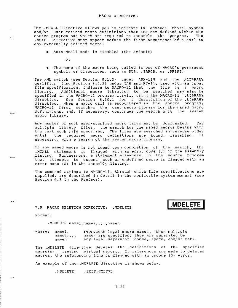
The
MCALL directive allows you to indicate in advance those system
and/or
user-defined macro definitions that are not defined within the
source
program but which are required to assemble the program
.
The
.MCALL
directive must appear before the first occurrence of a call to
any
externally defined macro
:
Auto-Mcall
mode is disabled (the default)
or
The
name of the macro being called is one of MACRO's permanent
symbols
or directives, such as SUB, ERROR, or PRINT
.
The
/ML switch (see Section 8
.1 .3)
under RSX-11M and the /LIBRARY
qualifier
(see Section 8
.2 .2)
under IAS and RT-11, used with an input
file
specification, indicate to MACRO-11 that the file is a macro
library .
Additional
macro libraries to be searched may also be
specified
in the MACRO-11 program itself, using the MACRO-11
LIBRARYdirective .
See
Section 6
.10 .1
for a description of the LIBRARY
directive .
When a macro call is encountered in the source program,
MACRO-11
first searches the user macro library for the named macro
definitions,
and, if necessary, continues the search with the system
macro
library
.
Any
number of such user-supplied macro files may be designated
.
Formultiple
library files, the search for the named macros begins with
the
last such file specified
.
The files are searched in reverse order
until
the required macro definitions are found, finishing, if
necessary,
with a search of the system macro library
.
If
any named macro is not found upon completion of the search, the
.MCALL
statement is flagged with an error code (U) in the assembly
listing .
Furthermore, a statement elsewhere in the source program
that
attempts to expand such an undefined macro is flagged with an
error
code (0) in the assembly listing
.
The
command strings to MACRO-11, through which file specifications are
supplied,
are described in detail in the applicable system manual (see
Section
0
.3
in the Preface)
.
7 .9
MACRO DELETION DIRECTIVE
:
Format :
.MDELETE
namel,name2,
. . .,namen
where :
namel,
name2, . . .namen
The
MDELETE
.MDELETE .EXIT,EXIT$S
MACRO
DIRECTIVES
.MDELETE
An
example of the MDELETE directive is
represent
legal macro names
.
When multiple
names
are specified, they are separated by
any
legal separator (comma, space, and/or tab)
.
directive
deletes the definitions
macro(s),
freeing virtual memory
.
If
macros,
the referencing line is flagged
7- 2 1
of
the
references
are made
with
an opcode (0)
shown
below
.
.MDELETE
specifiedto
deleted
error .


CHAPTER
8
IAS/RSX-11M/RSX-11M-PLUS
OPERATING PROCEDURES
MACRO-11
assembles one or more ASCII source files containing MACRO-11
statements
into a single relocatable binary object file
.
This binary
object
file contains the table of contents listing, the assembly
listing,
and the symbol table listing
.
An optional cross-reference
listing
of symbols and macros is available
.
A sample assembly listing
is
provided in Appendix H
.
8 .1
RSX-11M/RSX-11M-PLUS OPERATING PROCEDURES
On
RSX-11M and RSX-11M-PLUS systems, two command languages are
available :
the Monitor Console Routine (MCR) and the DIGITAL Command
Language
(DCL)
.
When you log onto the system, you are given either
MCR
or DCL as the default command language
.
Your default command
language
is contained in your account file
.
By
typing CTRL/C ("'C) from the monitor prompt, you can see the
explicit
prompt for the command language you are currently using
.
>
"C
MCR>
>
~C
DC
L>
You
can switch from one command language to the other
.
To switch from
DCL
to MCR, type the following command
:
DCL>
SET TERMINAL MCR
To
switch from MCR to DCL, type the following command
:
MCR>
SET /DCL=TI
:
In
addition to switching from one command language to the other, you
can
type a DCL command from a terminal set to MCR, and an MCR command
from
a terminal set to DCL, as shown below
:
MCR>
DCL cmd-string
DCL>
MCR cmd-string

8 .1 .1
Initiating MACRO-11 Under RSX-11M/RSX-11M-PLUS
The
following sections describe those MACRO-11 operating procedures
that
apply to both the Monitor Console Routine and the DIGITAL Command
Language .
Any one of the four methods shown below may be employed to
initiate
MACRO-11
.
8 .1 .1 .1
Method 1 - Direct MACRO-11 Call
MCR
Format
:
MCR>MACMAC>cmd-string
The
Monitor Console Routine (MCR) accepts MAC as input, causing
MACRO-11
to be activated
.
Since a command string is not present with
the
MCR line, MACRO-11 then solicits input with the prompting sequence
MAC>
and waits for command string input
.
After the assembly of the
indicated
files has been completed, MACRO-11 again solicits command
string
input with the MAC> prompting sequence
.
This process will be
repeated
until CTRL/Z ("Z) is entered
.
DCL
Format
:
DCL>
MACRO[/qualifier(s)]
File(s)?
filespec[/qualifiers]
. . .
DCL
accepts MACRO as input
.
In
addition, you may include the
qualifiers
contained in Table 8-3
.
Since no file specifications are
included
in the DCL command line, MACRO-11 solicits input with the
File(s)
prompt
.
You
can then enter the name of one or more source
files
plus any of the qualifiers listed in Table 8-4
.
When you press
RETURN,
MACRO-11 performs the assembly
.
8 .1 .1 .2
Method 2 - Single Assembly
MCR
Format
:
DCL
Format
:
8 .1 .1 .3
Method 3 - Install, Run Immediately, and Remove On Exit
Format :
IAS/RSX-11M/RSX-11M-PLUS
OPERATING PROCEDURES
MCR>MAC
cmd-string
DCL>
MACRO cmd-string
In
method 2, no prompting from
string
input is included in the
the
source files in the command
>RUN
$MAC
MAC>cmd-string
MACRO-11
occurs, since the command
command
line
.
MACRO-11 then assembles
string
and exits when finished
.

This
method is used when the MACRO-11 assembler is not permanently
installed
in the system
.
On RSX-11M, the system must be generated for
this
type of call support
.
MAC is run from the system directory
.MACRO-11
solicits command string input
.
The command string must have
the
MCR format even if run from a DCL terminal
.
When MACRO-11 exits,
it
is automatically removed from the system
.
If
the system has the "flying install" feature, the RUN $ calling
format
is not needed
.
8 .1 .1 .4
Method 4 - Using the Indirect Command Processor
MCR
Formats
:
MCR>MACMAC>@filespec
or
MCR>MAC
@filespec
or
MAC>RUN
$MAC[/UIC=[g,m]J
MAC>@filespec
These
forms use the indirect command processor, which effectively
accomplishes
the substitution of "@filespec" for the "cmd-string"
input
employed in methods 1 through 3
.
In these formats, the indirect
command
processor is passing commands to the assembler
.
The file
specified
as "@filespec" contains MACRO-11 command strings
.
After
this
file is opened, command lines are read from the file until the
end-of-file
is detected
.
Three nested levels of indirect files are
permitted
in MACRO-11
.
MCR
and DCL Format
:
IAS/RSX-11M/RSX-11M-PLUS
OPERATING PROCEDURES
DCL>
@filespec
These
forms use the indirect command processor to pass commands to the
command
language
.
This is the only form you can use with DCL
.
The
indirect
command file "@filespec" must contain one of the command
lines
to initiate MACRO-11 as listed in methods 1 through 3
.
NOTE
MACRO-11
can be terminated by entering a
CTRL/Z
("Z) at any time a request for
command
string input is present
.
8 .1 .2
Default File Specifications
MACRO-11
accepts as input or creates as output up to six types of
files .
When using the MACRO-11 assembler, you should keep in mind the
default
device, directory, name, and types listed in Table 8-1
.
Table
8-1
lists the default values for each file specification
.
-8-3

IAS/RSX-11M/RSX-11M-PLUS
OPERATING PROCEDURES
8 .1 .3
MCR Command String Format
Table
8-1
File
Specification Default Values
In
response to the MAC> prompting st-quence printed by MACRO-11, type
the
output and input file specifications in the form shown below
:
MAC>object,listing=srcl,src2, . . .,srcn
where :
object
represents
the binary object (output) file
.
listing
represents the assembly listing (output) file
containing
the table of contents, the assembly
listing,
and the symbol table
.
separates
output file specifications from input
file
specifications
.
srcl,
represent
the ASCII source (input) files
src2 . . . .
containing
the MACRO-11 source program or the
srcn
user-supplied
macro library files to be assembled
.
File DeviceDefault
Values
Directory Filename Type
Object Your
default
Current None OBJFile volume
Listing Device
used
Directory None LSTFile for
object
used
in
file object
file
Source Your
default
Current ; None MACFiles volume used
for
source
1
or
device of
last
source
file
speci-
fied
user Your
default
Current,
if
None MLBMacro volume macro
file
Library is
specified
first ;
if not,
directory
of
last
source
file
System Library (1,1] RSXMAC SMLMacro deviceLibrary
Indirect Your
default
Current None CMDCommand volumeFile

IAS/RSX-11M/RSX-11M-PLUS
OPERATING PROCEDURES
Only
two output file specifications in the command string will be
recognized
by MACRO-11
;
any more than two such files will be ignored
.No
limit is set on the number of source input files
.
If the entire
command
string is longer than 80 characters and less than or equal to
132
characters, a hyphen can be placed at the end of the first line as
a
continuation character
.
A
null specification in either of the output file specification fields
signifies
that the associated output file is not desired
.
A null
specification
in the input file field, however, is an error condition,
resulting
in the error message "MAC -- Illegal filename" on the
command
output device (see Section 8
.5) .
Note that the absence of
both
the device name (dev
:)
and the name of the file (filename
.type)from
a file specification is the equivalent of a null specification
.
NOTE
When
no listing file is specified, any
errors
encountered in the source program
are
printed on the terminal from which
MACRO-11
was initiated
.
When the /NL
switch
is used in the listing file
specification
without an argument, the
errors
and symbol table are output to
the
file specified
.
Each
file specification contains the following information
:
filespec
/switch
:value . . .
where :
filespec
is
the standard file specification
.
/switch
In
addition, the switch identifier may be
accompanied
by any number of the following values
:ASCII
character strings, octal numbers, or decimal
numbers .
The default assumption for a numeric
value
is octal
.
Decimal values must be followed
by
a decimal point (
.) .
Any
numeric value preceded by a number sign (#) is
regarded
as an explicit octal declaration
;
this
option
is provided for documentation purposes and
ready
identification of octal values
.
Also,
any numeric value can be preceded by a plus
sign
(+) or a minus (-) sign
.
The
positive
specification
is the default assumption
.
If
an
represents
an
option .
This
three
forms, as
function
desired
:
ASCII
name identifying a switch
switch
option may be specified in
shown
below, depending on the
/switch Invokes
the specified switch
action ./noswitch Negates
the specified switch
action ./-switch Also
negates the specified
switch
action
.

IAS/RSX-11M/RSX-11M-PLUS
OPERATING PROCEDURES
explicit
octal declaration is specified (#), the
sign
indicator, if included, must precede the
number
sign
.
All
switch values must be preceded by a colon (
:) .
The
switch specifications are interpreted in the
context
of the program to which they apply
.
The
switch
options applicable to MACRO-11 are
described
in Table 8-2 below
.
A
syntax error detected in the command string causes MACRO-11 to
output
the following error message to the command output device
:
MAC
-- Command syntax error
followed
by a copy of the entire command string
.
At
assembly time, you may want to override certain MACRO-11 directives
appearing
in the source program or to provide MACRO-11 with
information
establishing how certain files are to be handled during
assembly .
You can do so through one or more switches, which may be
selectively
invoked as additional parameters in each file
specification .
The
available switches for use in MACRO-11 file
specifications
under RSX-11M/RSA-11M-PLUS are listed in Table 8-2
.
Table
8-2
MACRO-11
File Specification Switches
Switch
Function
/LI :arg
Listing
control switches
;
these options accept
/NL :arg
ASCII
switch values (arg) which are equivalent
in
function and name to and override the
arguments
of the
LIST
and
NLIST
directives
specified
in the source program (see Section
6 .1 .1) .
This switch overrides the arguments and
remains
in effect for the entire assembly
process .
/EN :arg
Function
control switches
;
these options accept
/DS :arg
ASCII
switch values (arg) which are equivalent
in
function and name to and override the
arguments
of the ENABL and
DSABL
directives
specified
in the source program (see Section
6 .2 .1) .
This switch overrides the arguments and
remains
in effect for the entire assembly
process .
/ML
(see Note)
The
/ML switch, which takes no accompanying
switch
values, indicates to MACRO-11 that an
input
file is a macro library file
.
As noted in
Section
7
.8,
any macro that is defined
externally
must be identified in the MCALL
directive
before it can be retrieved from a
macro
library file and assembled with the user
program .
In locating macro definitions,
MACRO-11
initiates a fixed search algorithm,
8- 6
(continued
on next page)

Switch
/ML
(Cont
.)
/SP
/NOSP
/CR :[arg]
/LI :SRC :MEB
IAS/RSX-11M/RSX-11M-PLUS
OPERATING PROCEDURES
Table
8-2 (Copt
.)MACRO-11
File Specification Switches
Function
beginning
with the last user macro file
specified,
continuing in reverse order with each
such
file specified, and terminating, if
necessary,
with a search of the system macro
library
file
.
If a required macro definition is
not
found upon completion of the search, an
error
code (U) results in the assembly listing
.This
means that a user macro library file must
be
specified in the command line or by using the
MACRO-11
LIBRARY directive (see Section 6
.10 .1)prior
to the source file(s) that use macros
defined
in the library file
.
MACRO-11
does not pre-scan the command line for
macro
libraries
;
when a new source file is
needed,
it parses the next input file
specification .
If that file specification
contains
the /ML switch, it is appended to the
front
of the library file list
.
As a result, a
user
macro library file must be specified in the
command
line prior to the source files which
require
it, in order to resolve macro
definitions .
Spool
listing output (default value)
.
Do
not spool output
.
Produce
a cross-reference listing (see Section
8 .3) .
Switches
for the object file are limited to /EN and /DS
;
whenspecified,
they apply throughout the entire command string
.
Switch
options
for the listing file are limited to /LI, /NL, /SP, /CR, and
/NOSP .
Switches
for input files are limited to /ML, /EN, and /DS
;the
option /ML applies only to the file immediately preceding the
option
so specified, whereas the /EN and /DS options, as noted above,
are
also applicable to subsequent files in the command string
.
Multiple
occurrences of the same switch following a file specification
must
be avoided, because the accompanying values of a subsequent like
switch
specification override any previously-specified values
.
If two
such
switch values are desired, they can be specified in the form
shown
below
:

or
Qualifier
IAS/RSX-11M/RSX-11M-PLUS
OPERATING PROCEDURES
8 .1 .4
DCL Operating Procedures
RSX-11M/RSX-11M-PLUS
indicates its readiness to accept a command by
prompting
with the DCL prompt
.
In response to the prompt, enter the
command
string in one of the formats shown below
:
>MACRO[/qualifiers]FILE?
filespec[/qualifier[s]][,filespec[/qualifier[s]]
. . .]
[DCL]>;MACRO[/qualifiers]
filespec[/qualifier[s]] [,filespec[/qualifier[s]]
. . .]
where :
qualifiers
affect
either the entire command string
(command
qualifiers) or the filespec
(parameter
qualifiers)
.
See Table 8-3 for a
description
of the command qualifiers and
Table
8-4 for a description of the parameter
qualifiers .
filespec
is
the standard file specification shown in
Section
8
.4 .
You
use the comma (,) to separate file specifications
.
MACRO-11concatenates
all the files and then performs the assembly
.
/[NO]CROSS-REFERENCE
/DSABLE :arg/ENABLE :arg/DSABLE :(arg,arg . . .)/ENABLE :(arg,arg . . .)
Argument
ABSOLUTE
Table
8-3
DCL
Command Qualifiers
Function
Suppresses
or generates a
cross-reference
listing (see Section
8 .3) .
When the cross-reference is
generated,
a listing file is also
generated,
whether or not the /LIST
qualifier
is present in the command
string .
/NOCROSS
REFERENCE is the default
.
Overrides
the DSABLE or ENABLE
assembler
directives in the source
program .
When more than one argument
is
entered, arguments must be enclosed
in
parentheses and separated by
commas .
You
can specify any of the following
arguments
with the /DSABLE or /ENABLE
qualifier .
8-8
Enabling
this function causes all
relative
addresses (address mode
67)
to be assembled as absolute
addresses
(address mode 37)
.
(continued
on next page)

IAS/RSX-11M/RSX-11M-PLUS
OPERATING PROCEDURES
Table
8-3 (Cont
.)DCL
Command Qualifiers
Qualifier
Function
ABSOLUTE
(Cont
.)
By
default, the ABSOLUTE argument
is
disabled
.
AUTO
MCALL
Enabling
the AUTO-MCALL argument
causes
MACRO-11 to search all
known
macro libraries for a macro
definition
that matches any
undefined
symbols appearing in
the
opcode field of a MACRO-11
statement .
CARD
FORMAT
CASE
MATCH
By
default, this option is
disabled
and if MACRO-11 finds an
unknown
symbol in the opcode
field,
it either declares a (U)
undefined
symbol error, or
declares
the symbol as an
external
symbol, depending upon
the
GLOBAL argument described
below .
BINARY
Enabling
this function produces
'
absolute
binary output in
FILES-11
format
.
By
default, the BINARY argument
is
disabled
.
This
function, when enabled,
treats
columns 73 through the end
of
the line as comments
.
GLOBAL
Disabling
this function causes
MACRO-11
to flag all undefined
symbol
references with an error
code
(U) on the assembly listing
.
8- 9
By
default,
the
CARD
FORMAT
argument
is disabled
.
Enabling
the CASE MATCH argument
causes
the MACRO-11 conditional
assembly
directives IF IDN/
.IFDIF
to be alphabetically case
sensitive .
By
default these directives are
not
case sensitive
.
By
default, the GLOBAL argument
is
enabled and MACRO-11 treats
all
symbols that are undefined at
the
end of assembly pass 1 as
default
global references
.
(continued
on next page)

IAS/RSX-11M/RSX-11M-PLUS
OPERATING PROCEDURES
Table
8-3 (Copt
.)DCL
Command Qualifiers
Qualifier
Function
LOCAL
Enabling
the LOCAL argument
causes
the assembler to treat all
symbols
as local symbols
.
Whenenabled,
all global symbols are
flagged
with the U (undefined
symbol)
error message
.
By
default, the LOCAL argument is
disabled .
LOWER-CASE
Enabling
this function causes
MACRO-11
to accept lower-case
ASCII
input
.
Disabling
this function causes
MACRO-11
to convert lower-case
ASCII
input to upper-case
.
By
default, the LOWER-CASE
argument
is enabled
.
REGISTER_
Disabling
this function causes
DEFINITIONS
MACRO-11
to ignore the normal
register
definitions
.
By
default, register definitions
are
enabled
.
TRUNCATION
When
this function is enabled,
MACRO-11
performs floating-point
truncation .
When
this function is disabled,
MACRO-11
performs floating-point
rounding .
The
TRUNCATION argument is
disabled
by default
.
(continued
on next page)

IAS/RSX-11M/RSX-11M-PLUS
OPERATING PROCEDURES
Table
8-3 (Cont
.)DCL
Command Qualifiers
Qualifier
Function
/[NO]LIST[ :filespec]
Specifies
whether or not the assembler
should
create and print a listing
file .
You can include /LIST as a
qualifier
for either a command or a
file
specification
.
If /LIST
qualifies
the command, the listing
file
is both entered in your directory
and
printed on the line printer
.
If
you
do not include a file
specification,
the listing file has a
.LST
file type and is named after the
last
file named in the MACRO command
.The
listing file cannot be a library
file .
(The LINK command and all other
language
commands use the name of the
first
file named in the command as the
default
file name
.)
If /LIST qualifies
a
file specification, the file is
entered
in your directory but is not
printed
on the line printer
.
The
listing
file is named after the file
it
qualifies
.
The
default is /NOLIST
.
/NOLIST
is the default qualifier
.
/[NO]OBJECT[ :filespec]
Indicates
whether or not the assembler
should
create an object module
.
If
you
do not include a file
specification
in the command line, the
assembler
creates an object file with
the
same file name as the source file
and
an OBJ extension
.
/OBJECT
is the default qualifier
.
/[NO]SHOW :arg
overrides
the LIST and NLIST
/[NO]SHOW :(arg,arg . . .)
assembler
directives that may be
included
in the source file
.
You can
use
any of the following arguments
with
the /SHOW qualifier
.
Argument
BINARY
Controls
the listing of macro
expansion
binary code
.
CALLS
Controls
listing of macro calls
and
repeat range expansions
.
(continued
on next page)

IAS/RSX-11M/RSX-11M-PLUS
OPERATING PROCEDURES
Table
8-3 (font
.)DCL
Command Qualifiers
Qualifier
Function
COMMENTS
Controls
listing of comments
.
CONDITIONALS
Controls
listing of unsatisfied
conditional
coding
.
CONTENTS
Controls
listing of the table of
contents
during assembly pass 1
.
COUNTER
Controls
listing of the current
location
counter field
.
DEFINITIONS
Controls
listing of macro
definitions
and repeat range
expansions .
EXPANSIONS
Controls
listing of macro
expansions .
EXTENSIONS
Controls
listing of binary
expansions .
LISTING
DIRECTIVES
Controls
listing
of
listingcontrol
directives without
arguments,
that is, directives
that
alter the listing level
counter .
OBJECT
BINARY
Controls
listing of the generated
binary
code
.
SEQUENCE
NUMBERS
Controls
listing of source line
sequence
numbers
.
SOURCE
Controls
listing of source lines
.
SYMBOLS
Controls
listing of the symbol
table
resulting from the
assembly .
/[NO]WIDE
When
set to WIDE, the listing is
printed
in 132 column format
.
When
set
to /NOWIDE, the listing is printed
in
80 column format
.
/NOWIDE is the
default
qualifier
.

Qualifier
/LIBRARY
IAS/RSX-11M/RSX-11M-PLUS
OPERATING PROCEDURES
1 .
The following
FILNAM .MAC
into
Table
8-4
DCL
Parameter Qualifiers
Function
Specifies
that an input file is a macro library file
.
The
assembler processes the files listed in the
command
line in reverse order
.
Therefore, a library
file
cannot be the last file in the command line
.
8 .1 .5
MACRO-11 Command String Examples
MCR>
MAC FILNAM=FILNAM
DCL>
MACRO
FILE?
FILNAM
DCL>
MACRO FILNAM
MCR>
MAC TESTA=FILNAM
command
strings assemble the source file
a
relocatable object module named FILNAM
.OBJ .
2 .
The following command strings assemble the source file
FILNAM .MAC
and produce an object file with the name
TESTA .OBJ .
DCL>
MACRO/OBJECT
:TESTA
FILNAM
3 .
The following command strings concatenate and assemble the
source
files named FILNAM
.MLB,
TESTA
.MAC,
SPAN3
.MAC,
and
SHELL .MAC
and create an object file named SHELL
.OBJ .
MCR>
MAC SHELL=FILNAM/ML,TESTA,SPAN3,SHELL
DCL>
MACRO FILNAM/LIBRARY,TESTA,SPAN3,SHELL
4 .
The following command strings produce an object module and an
assembly
listing
.
Any LIST TTM or LIST COM directives in
the
source file are ignored
.
The listing produced by this
command
has no comments included and is printed in wide
format .
MCR>
MAC FILNAM,FILNAM/NL
:TTM :COM=FILNAM
DCL>
MACRO/LIST/NOSHOW
:COMMENTS/WIDE
FILNAM

8 .2
IAS MACRO-11 OPERATING PROCEDURES
The
following sections describe those MACRO-11 operating procedures
that
apply exclusively to the IAS system
.
8 .2 .1
Initiating MACRO-11 Under IAS
The
MACRO command, used under IAS, causes MACRO-11 to assemble one or
more
ASCII source files containing MACRO-11 statements into a
relocatable
binary object file
.
The assembler will also produce an
assembly
listing, followed by a symbol table listing
.
A
cross-reference
listing can also be produced by means of the
/CROSSREFERENCE
qualifier (see 8
.3,
below)
.
You
can input a MACRO-11 program either directly from the terminal
(interactive
mode) or from a batch file (batch mode)
.
For interactive
mode
use the MACRO command which can be issued whenever the IAS
Program
Development System (PDS) is at command level, a condition
signified
by the appearance of the prompt
:
For
batch mode use the $MACRO command
.
When
the assembly is completed, MACRO-11 terminates operations and
returns
control to PDS
.
(Refer to the IAS User's Guide for further
information
about interactive and batch mode operations
.)
8 .2 .2
IAS Command String
Formats :
Interactive
Mode
where :
PDS>
Batch
Mode
IAS/RSX-11M/RSX-11M-PLUS
OPERATING PROCEDURES
inputPDS>
MACRO qualifiers
filespec
/LIBRARY +
. . .
or
PDS>
MACRO qualifiers
inputFILES?
filespec /LIBRARY +
. . .
input$MACRO
qualifiers
filespec
/LIBRARY +
. . .
input
is
the specification of an input file
filespec
(see
Section 8
.4)
that contains MACRO-11
source
program code
.
When the program
consists
of multiple files, a plus sign
(+)
must be used to separate each file
specification
from the next
.
The "wild
card"
form of a file specification is
not
allowed
.
8-14

IAS/RSX-11M/RSX-11M-PLUS
OPERATING PROCEDURES
/LIBRARY
specifies
that an input file is a macro
library
file
.
Library
files hold the
definitions
of externally defined
macros .
As
noted in Section 7
.8,
an
externally
defined macro must be
identified
in an MCALL directive before
it
can be retrieved and assembled with
the
user program
.
When MACRO-11
encounters
an MCALL directive, a search
begins
for the definitions of the macros
listed .
The
search order is important because a
macro
might have two different
definitions
in library files LIB1 and
LIB2 .
For example, if you need the
definition
in LIB1, then you must place
LIB1
after LIB2 in the command line
because
MACRO-11 searches the last file
specified
in the command line first,
then
moves backwards through the files
given
until all have been searched
.
If
a macro's definition is not found in
any
of the files named by the user,
MACRO-11
automatically searches the
system
macro library
;
if the definition
is
still not found, an error code (U) is
generated
in the assembly listing
.
qualifiers
specifies
one or more of the following
:
output
produces
an object file as
/OBJECT[ :filespec]
specified
by filespec (see Section
8 .4) .
The
default is a file with
the
same filename as the last named
source
file and an OBJ extension
./OBJECT
is always the default
condition .
/NOOBJECT
does
not produce an object file
.
output
produces
an assembly listing file
/LIST[ :filespec]
according
to filespec (see Section
8 .4) .
If filespec is not
specified,
the listing is printed
on
the line printer
.
The default
in
interactive mode is /NOLIST and
in
batch mode is /LIST
.
/NOLIST
does
not produce a listing file
.The
default in interactive mode is
/NOLIST
and in batch mode is /LIST
.
NOTE
When
no listing file is specified, any
errors
encountered in the source program
are
displayed at the terminal from which
MACRO-11
was initiated
.

A
MACRO-11 command string can be specified using any one of the three
formats
shown above for the interactive and batch modes
.
In
interactive
mode, if the input file specification (filespec) does not
begin
on the same line as the MACRO command and its qualifiers, PDS
prints
the following prompting message
:
then
waits for the user to specify the input file(s)
.
In
batch mode, the $MACRO command and its arguments must appear on the
same
line unless the PDS line continuation symbol (-) is used
.
8 .2 .3
IAS Indirect Command Files
Format :
where :
FILES?
@filespec
IAS/RSX-11M/RSX-11M-PLUS
OPERATING PROCEDURES
/CROSSREFERENCE[ :argl . . .arg4]
produces
a cross-reference listing
.Argl
through arg4 are described in
Section
8
.3 .
This qualifier may be
abbreviated
to /C
.
@
specifies
that the name that follows is an
indirect
file
.
filespec
is
the file specification (see Section 8
.4)
of a
file
that contains a command string
.
The default
extension
for the file name is CMD
.
The
indirect command file facility of PDS can be used with MACRO-11
command
strings
.
This is accomplished by creating an ASCII file that
contains
the desired command strings (or portions thereof) in the
forms
shown in Section 8
.2 .2 .
When an indirect command file reference
is
used in a MACRO-11 command string, the contents of the specified
file
are taken as all or part of the command string
.
An
indirect command file reference must always be the rightmost entry
in
the command (see Section 8
.2. .4
for examples)
.
8 .2 .4
IAS Command String Examples
The
following examples show typical PDS MACRO-11 command strings
.
1 .
PDS> MACRO /NOLIST
FILES?
A+BOOT
.MAC ;3
In
this example, the source files A
.MAC
and BOOT
.MAC ;3
will
be
assembled to produce an object file called BOOT
.OBJ .
No
listing
will be produced
.

IAS/RSX-11M/RSX-11M-PLUS
OPERATING PROCEDURES
2 .
Where the indirect command file TEST
.CMD
contains the command
string
MACRO/OBJECT :MYFILE
A+B
the
command
:
PDS>@TEST
causes
MACRO-11 to assemble the two files A
.MAC
and B
.MACinto
an object file called MYFILE
.OBJ .
3 .
Where the indirect command file IND02
.CMD
contains the
command
string segment
:
ATEST/LIBRARY+BTEST+SRT1 .021
the
command
:
PDS>MACRO/LIST :DK1 :TST
@IND02
causes
MACRO-11 to assemble the files BTEST
.MAC
and SRT1
.021using
the macro library file ATEST
.MAC
to produce an object
file
named SRT1
.OBJ .
A listing file named TST
.LST
is placed
on
disk unit 1
.
4 .
$MACRO/LIST
:DKO :MICR/NOOBJECT
-
LIBl/LIBRARY+MICR .MAC ;002
In
this example, the library file is assembled with the file
MICR .MAC ;002 .
The program listing file named MICR
.LST
is
placed
on disk unit 0
.
8 .3
CROSS-REFERENCE PROCESSOR (CREF)
The
CREF processor is used to produce a listing that includes
cross-references
to symbols that appear in the source program
.
The
cross-reference
listing is appended to the assembly listing
.
Such
cross-references
are helpful in debugging and in reading long
programs .
A
cross-reference listing can include up to four sections
:
1 .
User-defined symbols
2 .
Macro symbols
3 .
Register symbols
4 .
Permanent symbols

where :
S
YM
/CR :
MAC
REGPSTSECERR
/CR :SYM
Sign
IAS/RSX-11M/RSX-11M-PLUS
OPERATING PROCEDURES
To
generate a cross-reference listing, specify the /CR switch in the
MACRO-11
command string
.
Optional arguments can also be specified
.The
form of the switch is
:
SYM
specifies
user-defined symbols (default)
MAC
specifies
macro symbols (default)
REG
specifies
register symbols
PST
specifies
permanent symbols
SEC
specifies
program sections
ERR
specifies
error lines (default)
If
you wish to generate listings for user-defined and macro symbols
only,
use /CR
.
No argument is necessary
.
However,
if an argument is specified, only that type of
cross-reference
listing is generated
.
For example
:
produces
a cross-reference listing of user-defined symbols only
.
Nolisting
of macro symbols is generated
.
Thus, to produce all six types
of
cross-reference listings, you must specify all six arguments (the
order
in which they are specified is not significant)
.
Use a colon to
separate
arguments
.
For example
:
/CR :REG :SYM :MAC :PST :SEC :ERR
The
CREF processor (CRF) is more fully described in the Utilities
Reference
Manual supplied with your system
.
Figure
8-1 illustrates a complete cross-reference listing
.
In
the
listing,
references are made in the form page-line
.
To make the
listing
more informative the CREF processor uses the following signs
:
Meaning
somewhere
in the source program the symbol listed is
defined
by a direct assignment statement
.
destructive
reference
;
at the
processor
the value of the symbol
previous
contents destroyed)
.
at
the line referenced by the processor
listed
is defined by a direct assignment
colon
sign (
:)
or a double colon sign (
: :) .
line
referenced by the
is
changed (its
the
symbol
statement,
a

IAS/RSX-11M/RSX-11M-PLUS
OPERATING PROCEDURES
R50UNP
MACRO VO5
.00
Saturday 08-Jan-83 11
:47
Pane S-1
Cross
reference table (CREF V05
.00)
R50UNP
2-16A
SYMBOL
2-17 2-25
R50UNP
MACRO V05
.00
Saturday 08-Jan-83 11
:47
Pane C-1
Cross
reference table (CREF V05
.00)
0-0.
ASS
.
0-0PURE
1
2-14
Figure
8-1 Sample CREF Listing
8 .4
IAS/RSX-11M/RSX-11M-PLUS FILE SPECIFICATION
Format :
where :
dev :[g,m]name .ext ;ver
dev :
is
the name of the device where the desired file
resides .
A
device name consists of two characters
followed
by a l- or 2-digit device unit number (octal)
and
a colon (for example, DP1
:,
DKO
:,
DT3
:) .
The
default
device is specified in Table 8-1
.
The default
device
under IAS is established initially by the system
manager
for each user and can be changed through the
SET
command
.
[g,m]
is
the User File Directory (UFD) code
.
This
code
consists
of a group number (octal), a comma (,) and an
owner
(member) number (octal) all enclosed in brackets
([]) .
An example of a UFD code is
:
[200,30] .
R50UNP MACRO
V05
.00 Saturday 08-Jan-83 11 :47 Page
R-1
Cross reference table (CREF
V05
.00)
RO 2-23* 2-32* 2-33* 2-43 2-45 2-48* 2-49*2-50* 2-51* 2-52
R1 2-18* 2-23R2 2-52*R3 2-19* 2-21* 2-33R4 2-18 2-17* 2-18 2-25 2-27*SP 2-18* 2-27

name
.ext
;ver
IAS/RSX-11M/RSX-11M-PLUS
OPERATING PROCEDURES
The
default UFD is equivalent to the User
Identification
Code (UIC) given at log-in time
.
Under
IAS,
the UFD can be changed through the SET DEFAULT
command .
is
the filename and consists of one through nine
alphanumeric
characters
.
There is no default for a
filename .
is
a 1- to 3-alphanumeric character filename extension
or
type that is preceded by a period (
.) .
An extension
is
normally used to identify the nature of the file
.Default
values depend on the context of the file
specification
and are as follows
:
.CMD
= Indirect command (input) file
.LST
= A listing (print format) file
.MAC
= MACRO-11 source module (input file)
.OBJ
= MACRO-11 object module (output file)
.CRF
= Intermediate CREF input file created by
MACRO-11 .
is
an octal number between 1 and 77777 that is used to
differentiate
between versions of the same file
.
This
number
is prefixed by a semicolon (
;) .
For
input files, the default value is the highest
version
number of the file that exists
.
For
output files, the default value is the highest
version
number of the file that exists increased by 1
.If
no version number exists, the value 1 is used
.
This
is the general form
IAS/RSX-11M/RSX-11M-PLUS
systems
.the
applicable system user's guide
Section
0
.3
in the Preface)
.
8 .5
MACRO-11 ERROR MESSAGES UNDER IAS/RSX-11M/RSX-11M-PLUS
MACRO-11
outputs an error message to the command output device when
one
of the error conditions described below is detected
.
MACRO-11
prints
below the error message the command line that caused the
If
the error is a INCLUDE or a LIBRARY
MACRO-11
prints below the error message both the
command
line that caused the error
.
MAC
-- Error message
MACRO-11
source line
MACRO-11
command line
for
a file specification in
Detailed
information is provided in
or
operating procedures manual (see
error .directive
file error,
source
line and the
These
error messages reflect operational problems and should not be
confused
with the error codes (see Appendix D) produced by MACRO-11
during
assembly
.

IAS/RSX-11M/RSX-11M-PLUS
OPERATING PROCEDURES
All
the error messages listed below, with the exception of the
"MAC
-- Command I/0 error" message, result in the termination of the
current
assembly
;
MACRO-11
then attempts to restart by reading
another
command line
.
In
the case of a command I/0 error, however,
MACRO-11
exits, since it is unable to obtain additional command line
input .
MAC
-- Command file/open failure
Either
the file from which MACRO-11 is reading a command could
not
be opened initially or between assemblies
;
or the indirect
command
file specified as "@filename" in the MACRO-11 command
line
could not be opened
.
See "OPEN FAILURE ON INPUT FILE"
.
MAC
-- Command I/0 error
An
error was returned by the file system during MACRO-11's
attempt
to read a command line
.
This is an unconditionally fatal
error,
causing MACRO-11 to exit
.
No MACRO-11 restart is
attempted
when this message appears
.
MAC
-- Command syntax error
An
error was detected in the syntax of the MACRO-11 command line
.
MAC
-- Illegal filename
Neither
the device name nor the filename was present in the input
file
specification (the input file specification was null), or a
wild
card convention (asterisk) was employed in an input or
output
file specification
.
Wildcard
options (*) are not permitted in MACRO-11 file
specifications .
MAC
-- Illegal switch
An
illegal switch was specified for a file, an illegal value was
specified
with a switch, or an invalid use of a switch was
detected
by MACRO-11
.
MAC
-- INCLUDE directive file error
The
file specified in the
INCLUDE
statement either does not
exist
or is invalid, the device specified in the command line is
not
available, or the INCLUDE stacking depth exceeds five
.
MAC
-- Indirect command syntax error
The
name of the indirect command file (@filename) specified in
the
MACRO-11 command line is syntactically incorrect
.
MAC
-- Indirect file depth exceeded
An
attempt to exceed the maximum allowable number of nested
indirect
command files has occurred
.
(Three levels of indirect
command
files are permitted in MACRO-11
.)
MAC
-- Insufficient dynamic memory
There
is not enough physical memory available for MACRO-11 to
page
its symbol table
.
Reinstall MACRO-11 in a larger partition,
or
see Appendix F
.3 .
MAC
-- Invalid format in macro library
The
library file has been corrupted, or it was not produced by
the
Librarian Utility Program (LBR)
.

IAS/RSX-11M/RSX-11M-PLUS
OPERATING PROCEDURES
MAC
-- I/0 error on input file
In
reading a record from a source input file or macro library
file,
the file system detected an error
;
for example, a line
containing
more than 132(10) characters was encountered
.
This
message
may also indicate that a device problem exists or that
either
a source file or a macro library file has been corrupted
with
incorrect data
.
MAC
-- I/0 error on macro library file
Same
meaning as I/0 error on input file, except that the file is
a
macro library file and not a source input file
.
MAC
-- I/0 error on output file
In
writing a record to the object output file or the listing
output
file, an error was detected by the file system
.
This
message
may also indicate that a device problem exists or that
the
device is full
.
MAC
-- I/0 error on work file
A
read or write error occurred on the work file used to store the
symbol
table
.
This error is most likely caused by a problem on
the
device or by attempting to write to a device that is full
.
MAC
-- LIBRARY directive file error
The
file specified in the
LIBRARY
statement either does not
exist
or is invalid, the file specification in the LIBRARY
directive
is for a non-random access device, the device specified
in
the command line is not available, or the LIBRARY stacking
depth
exceeds the maximum depth allowed
.
MAC
-- Open failure on input file
1 .
Specified device does not exist
.2 .
The volume is not mounted
.3 .
A problem exists with the device
.4 .
Specified directory file does not exist
.5 .
Specified file does not exist
.6 .
User does not have access privilege to the file directory or
to
the file itself
.
MAC
-- Open failure on output file
1 .
Specified device does not exist
.2 .
The volume is not mounted
.3 .
A problem exists with the device
.4 .
Specified directory file does not exist
.5 .
User does not have access privilege to the file directory
.6 .
The volume is full or the device is write protected
.7 .
There is insufficient space for File Control Blocks
.
MAC
-- 64K storage limit exceeded
64K
words of work file memory are available to MACRO-11
.
Thismessage
indicates that the assembler has generated so many
symbols
(about 13,000 to 14,000) that it has run out of space
.Either
the source program is too large to start with, or it
contains
a condition that leads to excessive size, such as a
macro
expansion that recursively calls itself without a
terminating
condition
.

9 .1
MACRO-11 UNDER RSTS
The
only way a MACRO-11 program can run on a RSTS system is through
either
the RT-11 or RSX run-time systems
.
9 .1 .1
RT-11 Through RSTS
CHAPTER
9
RSTS/RT-11
OPERATING PROCEDURES
There
are two ways to run a MACRO program under the RT-11 run-time
system :
1 .
Use the RT-11 Emulator
.
This is done by typing
:
SW
RT11
.The
terminal will respond with the RT-11 prompt (a dot
printed
by the keyboard monitor)
.
You can then use the RT-11
commands
(see Section 9
.2) .
2 .
Type the command
:
RUN $MACRO
.SAV .
The terminal will respond
with
an asterisk (*) prompt
.
You can then enter a command
string
of the form
:
OBJFIL,LSTFIL=SRC . . .SRC6
where :
9 .1 .2
RSX Through RSTS
in
this command
.
To
run a MACRO program under the RSX run-time system, type the
command :
RUN $MAC
.TSK .
The terminal will respond with
:
MAC>
In
answer you enter a command string of the form
:
OBJFIL,LSTFIL=SRC . . .SRCN
OBJFIL is
an object (output)
file
with the default
extension
OBJ
.
LSTFIL is
a listing (output)
file
with the default
extension
LST
.
SRC . . . are
source (input)
files
with the default
SRC6 extension
MAC
.
Six
input
files are allowed
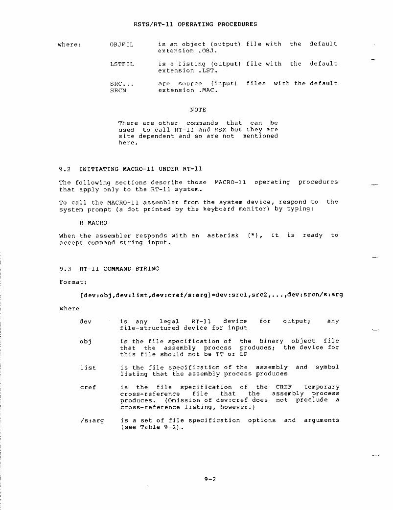
where :
where
R
MACRO
NOTE
There
are other commands that can be
used
to call RT-11 and RSX but they are
site
dependent and so are not mentioned
here .
9 .2
INITIATING MACRO-11 UNDER RT-11
The
following sections describe those MACRO-11 operating procedures
that
apply only to the RT-11 system
.
To
call the MACRO-11 assembler from the system device, respond to the
system
prompt (a dot printed by the keyboard monitor) by typing
:
When
the assembler responds with an asterisk (*), it is ready to
accept
command string input
.
9 .3
RT-11 COMMAND STRING
Format :
[dev :obj,dev :list,dev :cref/s :arg]=dev :srcl,src2, . . .,dev :srcn/s :arg
dev
is
any legal RT-11 device for output
;
any
file-structured
device for input
obj
is
the file specification of the binary object file
that
the assembly process produces
;
the device for
this
file should not be TT or LP
list
is
the file specification of the assembly and symbol
listing
that the assembly process produces
cref
is
the file specification of the CREF temporary
cross-reference
file that the assembly process
produces .
(Omission of dev
:cref
does not preclude a
cross-reference
listing, however
.)
/s :arg
is
a set of file specification options and arguments
(see
Table 9-2)
.
RSTS/ T-11
OPERATING PROCEDURES
OBJFIL is
an object (output) file with the default
extension
OBJ
.
LSTFIL is
a listing (output) file with the default
extension
LST
.
SRC . . . are
source (input) files with the default
SRCN extension .MAC. .

srcl,
represent
the ASCII source (input) files containing the
src2 . . . .
MACRO-11 source program or the user-supplied macro
srcn
library
files to be assembled
.
You can specify as many
as
six source files
.
The
following command string calls for an assembly that uses one
source
file plus the system MACRO library to produce an object file
BINF .OBJ
and a listing
.
The listing goes directly to the line
printer .
*DK :BINK .OBJ,LP :=DK :SRC .MAC
RSTS/RT- 1 1
OPERATING PROCEDURES
All
output file specifications are optional
.
The
system does not
produce
an output file unless the command string contains a
specification
for that file
.
The
system determines the file type of an output file specification by
its
position in the command string, as determined by the number of
commas
in the string
.
For example, to omit the object file, you must
begin
the command string with a comma
.
The following command produces
a
listing, including cross-reference tables, but not binary object
files .*,LP :/C=(source
file specification)
Notice
that you need not include a comma after the final output file
specification
in the command string
.
Table
9-1 lists the default values for each file specification
.
Table
9-1
Default
File Specification Values
FileDefaultDevice
DefaultFile
Name
DefaultFile
Type
Object DK : Must
specify
OBJ
Listing Same
as for object
Must
specify
LSTfile
Cref DK : Must
specify
TMP
First
source
DK : Must
specify
MAC
Additional
source
Same
as for preceding
Must
specify
MACsource
file
System
MACRO
System
device SY
: SYSMAC SMLLibrary
User
MACRO
DK :
if first file,
must
specify
MLBLibrary otherwise
same as for
preceding
source file

RSTS/RT- 1 1
OPERATING PROCEDURES
NOTE
Some
assemblies need more symbol table
space
than available memory can contain
.the
system
a
temporary work
provide
extended
When
this occurs
automatically
creates
file
called WRK
.TMP
to
symbol
table space
.
The
default device
To
cause the
different
device,
command :
.ASSIGN
dev
:
WF
where :
dev
9 .4
FILE SPECIFICATION OPTIONS
WRK .TMP
is DK
.assign
a
following
forsystem
to
enter
the
is
the file-structured
device
that will hold
WRK .TMP .
At
assembly time you may need to override certain MACRO directives
appearing
in the source programs
.
You
may also need to direct
MACRO-11
on the handling of certain files during assembly
.
You
can
satisfy
these needs by using the switches described in Table 9-2
.
Option
/L :arg/N :arg
/E :arg/D :arg
Table
9-2
File
Specification Options
Listing
control switches
;
these options accept ASCII
switch
values (arg) which are equivalent in function
and
name to the arguments of the LIST and NLIST
in
the source program (see
switch
overrides the arguments
remains
in effect for the
directives
specified
Section
6
.1 .1) .
This
of
the directives and
entire
assembly process
.
Function
control switches
;
these options accept ASCII
switch
values (arg) which are equivalent in function
and
name to the arguments of the ENABL and DSABL
in
the source program (see
switch
overrides the arguments
remains
in effect for the
directives
specified
Section
6
.2 .1) .
This
of
the directives and
entire
assembly process
.
Usage
(continued
on next page)

Option
/M
/C :arg
RSTS/RT-11
OPERATING PROCEDURES
Table
9-2 (Cont
.)File
Specification Options
Usage
Indicates
input file is MACRO library file
.
When the
assembler
encounters an MCALL directive in the
source
code, it searches macro libraries according to
their
order of appearance in the command string
.When
it locates a macro record whose name matches
that
given in the MCALL, it assembles the macro as
indicated
by that definition
.
Thus, if two or more
macro
libraries contain definitions of the same macro
name,
the macro library that appears rightmost in the
command
string takes precedence
.
Consider
the following command string
:
*(output
file specification)=ALIB/M,
BLIB/M,XIZ
two
macro libraries, ALIB
.MLBa
macro called BIG, but with
Then,
if source file XIZ
systemas
it
Assume
that each of the
and
BLIB
.MLB,
contain
different
definitions
.contains
a macro call MCALL BIG, the
includes
the definition of BIG in the program
appears
in the macro library BLIB
.
If
the command string does not include the standard
system
macro library SYSMAC
.SML,
the system
automatically
includes it as the first source file in
the
command string
.
Therefore, if macro library
ALIB .MLB
contains a definition of a macro called READ,
that
definition of READ overrides the standard READ
macro
definition in SYSMAC
.SML .
Controls
contents of cross-reference listing
.
The
/M switch affects only the source file to which it
The
other options affect the entire command string
.
9 .5
CROSS-REFERENCE (CREF) TABLE GENERATION OPTION
is
appended
.
inprogram,
identifying the statements that define and use
A
cross-reference (CREF) table lists all or a subset of the symbols
a
source
symbols .
9 .5 .1
Obtaining a Cross-Reference Table
To
obtain a CREF table you must
command
string
.
Usually you
assembly
listing file specification
.
include
the /C
:arg
option in the
include
the /C
:arg
option with the

RSTS/RT- 1 1
OPERATING PROCEDURES
If
the command string does not include a cref file specification, the
system
automatically generates a temporary file on device DK
: .
If you
need
to have a device other than DK
:
contain the temporary cref file,
you
must include the dev
:cref
field in the command string
.
A
complete CREF listing contains the following six sections
:
1 .
A cross reference of program symbols--labels used in the
program
and symbols followed by an operator
.
2 .
A cross reference of register symbols
.
These symbols are R0,
R1,
R2, R3, R4, R5, SP, and PC
.
3 .
A cross reference of MACRO symbols--those symbols defined by
.MACRO
and MCALL directives
.
4 .
A cross reference of permanent symbols--all operation
mnemonics
and assembler directives
.
5 .
A cross reference of program sections--the names you specify
as
operands of
.CSECT
or PSECT directives
.
6 .
A cross reference of errors--the system groups and lists all
flagged
errors from the assembly by error type
.
You
can include any or all of these six sections on the
cross-reference
listing by specifying the appropriate arguments with
the
/C option
.
These arguments are listed and described in Table 9-3
.
Argument
Table
9-3
/C
Option Arguments
CREF
Section
S
User
defined symbols
R
Register
symbols
M
MACRO
symbolic names
P
Permanent
symbols including instructions and
C
Control
and program sections
E
Error
code grouping
NOTE
Specifying
/C with no arguments is
equivalent
to specifying /C
:S :M :E .
That
special
case excepted, you must
explicitly
request each CREF section by
including
its arguments
.
No
cross-reference
file occurs if the /C
option
is not specified, even if the
command
string includes a CREF file
specification .
directives

9 .5 .2
Handling Cross-Reference Table Files
When
you request a cross-reference listing by means of the /C option,
you
cause the system to generate a temporary file, DK
:CREF .TMP .
If
device DK
:
is write-locked or if it contains insufficient free
space
for the temporary file, you can allocate another device for the
file .
To allocate another device, specify a third output file in the
command
string
;
that is, include a dev
:cref
specification
.
(You must
still
include the /C option to control the form and content of the
listing .
The dev
:cref
specification is ignored if the /C option is
not
also present in the command string
.)
The
system then uses the dev
:cref
file instead of DK
:CREF .TMP
and
deletes
it automatically after producing the CREF listing
.
The
following command string causes the system to use RK2
:TEMP .TMP
as
the
temporary CREF file
.
*,LP :,RK2 :TEMP .TMP=SOURCE/C
Another
way to assign an alternative device for the CREF
.TMP
file is
to
enter the following command prior to entering R MACRO
:
.ASSIGN
dev
:CF
RSTS/RT- 1 1
OPERATING PROCEDURES
This
method is preferred if you intend to do several assemblies, as it
relieves
you from having to include the dev
:cref
specification in each
command
string
.
If you enter the ASSIGN dev
:
CF command, and later
include
a cref specification in a command string, the specification in
the
command string prevails for that assembly only
.
The
system lists requested cross-reference tables following the MACRO
assembly
listing
.
Each table begins on a new page
.
The
system prints symbols and also symbol values, control sections,
and
error codes, if applicable, beginning at the left margin of the
page .
References to each symbol are listed on the same line,
left-to-right
across the page
.
The system lists references in the
form
P-L
;
where P is the page in which the symbol, control section,
or
error code appears, and L is the line number on the page
.
A
number sign (#) next to a reference indicates a symbol definition
.An
asterisk (*) next to a reference indicates a destructive
reference--an
operation that alters the contents of the addressed
location .
9 .5 .3
MACRO-11 Error Messages Under RT-11
MACRO-11
outputs an error message to the command output device when
one
of the error conditions described below is detected
.
MACRO-11
prints
below the error message the command line that caused the error
.If
the error is a INCLUDE or a LIBRARY directive file error,
MACRO-11
prints below the error message both the source line and the
command
line that caused the error
.
?MACRO-s-Error
message
MACRO-11
source line
MACRO-11
command line

The
s in the error message represents the letter code that indicates
the
severity level of the error
.
These
error messages reflect operational problems and should not be
confused
with the error codes (see Appendix D) produced by MACRO-11
during
assembly
.
Error
Message
Meaning
?MACRO-F-Device
full DEV
:The
output volume does not have sufficient
room
for an output file specified in the
command
string
.
?MACRO-F-File
not found DEV
:FILNAM .TYPAn
input file in the command line does not
exist
on the specified device
.
?MACRO-F- .INCLUDE
directive file error
The
file specified in the INCLUDE statement
either
does not exist or is invalid, the
device
specified in the command line is not
available,
or the INCLUDE stacking depth
exceeds
five
.
?MACRO-F-Insufficient
memory
MACRO
does not have the minimum amount of
memory
(16K words) necessary to run
.
?MACRO-F-Invalid
command
The
command line contains a syntax error or
specifies
more than six input files
.
?MACRO-F-Invalid
device
RSTS/RT-11
OPERATING PROCEDURES
A
device specified in the command line does
not
exist on the system
.
?MACRO-F-Invalid
macro library
The
library file has been corrupted or it was
not
produced by the RT-11 librarian, LIBR
.
?MACRO-F-Invalid
option
:
/x
The
specified option was not recognized by
the
program
.
?MACRO-F-I/O
error on DEV
:FILNAM .TYPA
hardware error occurred while attempting to
read
from or write to the device on the
specified
file
.
?MACRO-F-1/0
error on work file
MACRO
failed to open, read, or write to its
work
file, WRK
.TMP .

RSTS/RT-11
OPERATING PROCEDURES
?MACRO-F- .LIBRARY
directive file error
The
file specified in the LIBRARY statement
either
does not exist or is invalid, the file
specification
in the LIBRARY directive is
for
a non-random access device, the device
specified
in the command line is not
available,
or the
LIBRARY
stacking depth
exceeds
the maximum depth allowed
.
?MACRO-F-Protected
file already exists DEV
:FILNAM .TYPAn
attempt was made to create a file having
the
same name as an existing protected file
.
?MACRO-F-Storage
limit exceeded (64K)
MACRO's
Virtual Symbol Table can store
symbols
and macros up to 64K in any
combination .
Your program contains more than
64K
worth of one or both of these elements
.
?MACRO-W-I/O
error on CREF file
:
CREF aborted
MACRO
ran out of device space while writing
the
cref file, or a hardware error has
occurred .
The cref file is aborted but
assembly
continues
.


A .1
ASCII CHARACTER SET
APPENDIX
A
MACRO-11
CHARACTER SETS
0
024
DC4
Device
control 4
;
turns punch or
auxiliary
off
.
CONTROL/T (AUX
OFF) .
EvenParityBit
7-BitOctalCode Character Remarks
0 000 NUL Null,
tape feed, CONTROL/SHIFT/P
.1 001 SOH start
of heading
;
also SOM, start
of
message, CONTROL/A
.1 002 STX Start
of text
;
also EOA, end of
address,
CONTROL/B
.0 003 ETX End
of text
;
also EOM, end of
message,
CONTROL/C
.1 004 EOT End
of transmission (END)
;
shuts
off
TWX machines, CONTROL/D
.0 005 ENQ Enquiry
(ENQRY)
;
also WRU,
CONTROL/E .0 006 ACK Acknowledge ;
also RU, CONTROL/F
.1 007 BEL Rings
the bell
.
CONTROL/G
.1 010 BS Backspace ;
also FEO, format
effector .
backspaces some
machines,
CONTROL/H
.0 011 HT Horizontal
tab
.
CONTROL/I
.0 012 LF Line
feed or Line space (new line)
;advances
paper to next line,
duplicated
by CONTROL/J
.1 013 VT Vertical
tab (VTAB)
.
CONTROL/K
.0 014 FF Form
Feed to top of next page
(PAGE) .
CONTROL/L
.1 015 CR Carriage
return to beginning of
line ;
duplicated by CONTROL/M
.1 016 SO Shift
out
;
changes ribbon color to
red .
CONTROL/N
.0 017 SI Shift
in
;
changes ribbon color to
black .
CONTROL/0
.1 020 DLE Data
link escape
.
CONTROL/P (DC0)
.0 021 DC1 Device
control 1
;
turns
transmitter
(READER) on, CONTROL/Q
(X
ON)
.
0 022 DC2 Device control
2 ;
turns punch or auxiliary on
.CONTROL/R
(TAPE, AUX ON)
.1 023 DC3 Device
control 3
;
turns
transmitter
(READER) off, CONTROL/S
(X
OFF)
.

MACRO-11
CHARACTER SETS
A- 2
EvenParityBit
7-BitOctalCode Character Remarks
1 025 NAK Negative
acknowledge
;
also ERR,
ERROR .
CONTROL/U
.
1 026 SYN Synchronous
file (SYNC)
.CONTROL/V .
0 027 ETB End
of transmission block
;
also
LEM,
logical end of medium
.CONTROL/W .
0 030 CAN Cancel
(CANCL)
.
CONTROL/X
.1 031 EM End
of medium
.
CONTROL/Y
.1 032 SUB Substitute .
CONTROL/Z
.0 033 ESC Escape .
CONTROL/SHIFT/K
.1 034 FS File
separator
.
CONTROL/SHIFT/L
.0 035 GS Group
separator
.
CONTROL/SHIFT/M
.0 036 RS Record
separator
.
CONTROL/SHIFT/N
.1 037 US Unit
separator
.
CONTROL/SHIFT/0
.1 040 SP Space .0 041 !0 042 "1 043 #0 044 $1 0451 046 &0 047 ' Accent
acute or apostrophe
.0 0501 051 )1 0520 053 +1 054 ,0 055 -0 0561 057 /0 060 01 061 11 052 20 063 31 064 40 065 50 066 61 067 71 070 80 071 90 0721 073 ;0 074 <1 075 =1 076 >0 077 ?1 100 @0 101 A0 102. B1 103 C0 104 D1 105 E1 106 F0 107 G0 110 H0 111 I
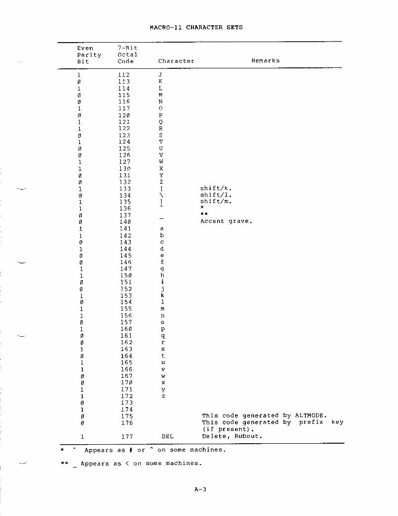
*
Appears as # or " on some machines .
MACRO-11 CHARACTER SETS
key
Appears as < on some machines .
A- 3
EvenParityBit7-BitOctalCode Character Remarks
1 112 J0 113 K1 114 L0 115 M0 116 N1 117 00 120 P1 121 Q1 122 R0 123 S1 124 T0 125 u0 126 V1 127 w1 130 X0 131 Y0 132 z1 133 [ shift/k .0 134 \ shift/1 .1 135 ] shift/m .1 1360 137 **0 140 _ Accent grave .1 141 a1 142 b0 143 c1 144 d0 145 e0 146 f1 147 g1 150 h0 151 i0 152 j1 153 k0 154 11 155 m1 156 n0 157 01 160 p0 161 q0 162 r1 163 s0 164 t1 165 u1 166 v0 167 w0 170 x1 171 y1 172 z0 1731 1740 175 This code generated by ALTMODE .0 176 This code generated by prefix(if present) .1 177 DEL Delete, Rubout .

A .2
47*50**2+47*50+47=174777
X=1130002=002400B=000002
X2B=115402
MACRO-11
CHARACTER SETS
The
maximum Radix-50 value is, thus,
The
following table provides a convenient means of translating between
the
ASCII character set and its Radix-50 equivalents
.
For example,
given
the ASCII string X2B, the Radix-50 equivalent is (arithmetic is
performed
in octal)
:
Single
First
Char .or
Char .SecondCharacter
ThirdCharacter
Space 000000 Space 000000 Space 000000A 003100 A 000050 A 000001B 006200 B 000120 B 000002C 011300 C 000170 C 000003D 014400 D 000240 D 000004E 017500 E 000310 E 000005F 022600 F 000360 F 000006G 025700 G 000430 G 000007H 031000 H 000500 H 000010I 034100 1 000550 1 000011J 037200 1 000620 1 000012K 042300 K 000670 K 000013L 045400 L 000740 L 000014M 050500 M 001010 M 000015N 053600 N 001060 N 0000160 056700 0 001130 0 000017P 062000 P 001200 P 000020Q 065100 Q 001250 Q 000021R 070200 R 001320 R 000022S 073300 S 001370 S 000023T 076400 T 001440 T 000024U 101500 U 001510 U 000025
RADIX-50
CHARACTER SET
Character
ASCIIOctal
EquivalentRadix-50Equivalent
Space 40 0
A-Z 101-132. 1-32
$ 44 33
56 34
Unused 35
0-9 60-71 36-47

MACRO-11 CHARACTER SETS
SingleFirst
Char .orChar . SecondCharacter ThirdCharacterV 104600 V 001560 V 000026W 107700 W 001630 w 000027X 113000 X 001700 X 000030Y 116100 Y 001750 Y 000031Z 121200 Z 002020 Z 000032$ 124300 $ 002070 $ 000033127400 002140 000034Unused 132500 Unused 002210 Unused 0000350 135600 0 002260 0 0000361 140700 1 002330 1 0000372 144000 2 002400 2 0000403 147100 3 002450 3 0000414 152200 4 002520 4 0000425 155300 5 002570 5 0000436 160400 6 002640 6 0000447 163500 7 002710 7 0000458 166600 8 002760 8 0000469 171700 9 003030 9 000047


APPENDIX
B
MACRO-11
ASSEMBLY LANGUAGE AND ASSEMBLER DIRECTIVES
B .1
SPECIAL CHARACTERS
Character
Function
Label
terminator
-
Direct
assignment operator
Register
term indicator
tab
Item
terminator or field terminator
space
Item
terminator or field terminator
Immediate
expression indicator
@
Deferred
addressing indicator
(
Initial
register indicator
Terminal
register indicator
(comma)
Operand
field separator
Comment
field indicator
+
Arithmetic
addition operator or auto
increment
indicator
-
Arithmetic
subtraction operator or auto
decrement
indicator
*
Arithmetic
multiplication operator
/
Arithmetic
division operator
Logical
AND operator
!
Logical
OR operator
"
Double
ASCII character indicator
'
(apostrophe)
Single
ASCII character indicator or
concatenation
indicator
Assembly
location counter
<
Initial
argument indicator
>
Terminal
argument indicator
Universal
unary operator or argument
indicator\
Macro
call numeric argument indicator
vertical
tab
Source
line terminator
B .2
SUMMARY OF ADDRESS MODE SYNTAX
Symbols
used in the table
:
n
is
an integer, 0 to 7, representing a register number
R
is
a register expression
E
is
an expression
ER
is
either a register expression or an expression whose value
is
in the range 0 to 7
.

MACRO-11
ASSEMBLY LANGUAGE AND ASSEMBLER DIRECTIVES
Meaning
Register
R contains the
operand .
Register
R contains the ad-
dress
of the operand
.
The
contents of the register
specified
as (ER) are
incremented
after being used
as
the address of the operand
.
The
register specified as (ER)
contains
the pointer to the
address
of the operand
;
the
register
(ER) is incremented
after
use
.
The
contents of the register
specified
as (ER) are
decremented
before being used
as
the address of the operand
.
The
contents of the register
specified
as (ER) are
decremented
before being used
as
the pointer to the address
of
the operand
.
The
expression E, plus the
contents
of the register
specified
as (ER), form the
address
of the operand
.
The
expression E, plus the
contents
of the register
specified
as (ER), yield a
pointer
to the address of the
operand .
the
theaddress
of the operand
.
The
address of the operand E,
relative
to the instruction,
follows
the instruction
.
The
address of the operand is
pointed
to by E whose address,
relative
to the instruction,
follows
the instruction
.
Format
AddressModeName
AddressModeNumber
R Register On
@R
or
Register In(ER) deferred
(ER)+ Autoincrement 2.n
@(ER)+ Autoincrement 3nDeferred
-(ER) Autodecrement 4n
@-(ER) Autodecrement 5nDeferred
E(ER) Index 6n
@E(ER) Index
Deferred
7n
#E Immediate 27
@#E Absolute 37
E Relative 67
@E Relative 77Deferred
The
expression
E isoperand
itself
.
The
expression
E is

B .3
ASSEMBLER DIRECTIVES
The
MACRO-11 assembler directives are summarized in the following
table .
For a detailed description of each directive, the table
contains
references to the appropriate sections in the body of the
manual .
SectionForm
Reference
Operation
MACRO-11
ASSEMBLY LANGUAGE AND ASSEMBLER DIRECTIVES
5 .3 .3
Followed by one ASCII character
7 .3 .7
a single quote (apostrophe)
generates
a word which contains the
7-bit
ASCII representation of the
character
in the low-order byte and
zero
in the high-order byte
.
Thischaracter
is also used as a
concatenation
indicator in the
expansion
of macro arguments
.
6 .3 .3 Followed
by two ASCII characters a
double
quote generates a word which
contains
the 7-bit ASCII
representation
of the two
characters .
The first character is
stored
in the low-order byte
;
the
second
character is stored in the
high-order
byte
.
"Bn 6 .4 .1 .2 A
temporary radix control, causes
the
value n to be treated as a
binary
number
.
"Cexpr 6 .4 .2 .2 A
temporary numeric control, causes
the
expression's value to be ones-
complemented ."Dn 6 .4 .1 .2 A
temporary radix control, causes
the
value n to be treated as a
decimal
number
.
"Fn 6 .4 .2 .2 A
temporary numeric control, causes
the
value n to be treated as a
sixteen-bit
floating-point number
.
On 6 .4 .1 .2 A
temporary radix control, causes
the
value n to be treated as an
octal
number
."Rccc 6 .3 .7 Converts
ccc to Radix-50 form
.
.ASCII
/string/
6 .3 .4 Generates
a block of data
containing
the ASCII equivalent of
the
character string (enclosed in
delimiting
characters), one
character
per byte
.

MACRO-11
ASSEMBLY LANGUAGE AND ASSEMBLER DIRECTIVES
Operation
Generates
a block of data
containing
the ASCII equivalent of
the
character string (enclosed in
delimiting
characters), one
character
per byte, with a zero
byte
terminating the specified
string .
Begins
or resumes the absolute
program
section
.
Reserves
a block of storage space
whose
length in bytes is determined
by
the specified expression
.
Reserves
a block of storage space
whose
length in words is determined
by
the specified expression
.
Generates
successive bytes of data
;each
byte contains the value of the
corresponding
specified expression
.
Enables
the cross-reference listing
for
the specified symbol list
.
If
a
symbol list is not specified,
this
directive reenables the
cross-reference
listing for all
symbols
in the program
.
Begins
or resumes named or unnamed
relocatable
program section
.
This
directive
is provided for
compatibility
with other PDP-11
assemblers .
Disables
the function specified by
the
argument
.
Enables
(invokes) the function
specified
by the argument
.
Indicates
the logical end of the
source
program
.
The optional
argument
specifies the transfer
address
where program execution is
to
begin
.
Indicates
the end of a conditional
assembly
block
.
Indicates
the end of the current
repeat
block, indefinite repeat
block,
or macro definition
.
The
optional
name, if used, must be
identical
to the name specified in
the
macro definition
.
FormSectionReference
.ASCIZ
/string/
6 .3 .5
.ASECT 6 .7 .2
.BLKB
exp
6 .5 .3
.BLKW
exp
6 .5 .3
.BYTE
expl,exp2
. . . 6 .3 .1
.CROSS
syml,sym2
. . . . 6 .2 .2
.CSECT
[name]
6 .7 .2
.DSABL
arg
6 .2 .1
.ENABL
arg
6 .2 .1
.END
[exp]
6 .6
.ENDC 6 .9 .1
.ENDM
[name]
7 .1 .2

MACRO-11
ASSEMBLY LANGUAGE AND ASSEMBLER DIRECTIVES
Operation
Indicates
the end of the current
repeat
block
.
This directive is
provided
for compatibility with
other
PDP-11 assemblers
.
A
user-invoked error directive,
causes
output to the listing file
or
the command output device
containing
the optional expression
and
the statement containing the
directive .
Ensures
that the current location
counter
contains an even address by
adding
1 if it is odd
.
Generates
successive 2-word
floating-point
equivalents for the
floating-point
numbers specified as
arguments .
Generates
successive 4-word
floating-point
equivalents for the
floating-point
numbers specified as
arguments .
Defines
the symbol(s) specified as
global
symbol(s)
.
Provides
a means of labeling the
object
module with the program
version
number
.
The version number
is
the Radix-50 string appearing
between
the paired delimiting
characters .
Begins
a conditional assembly block
of
source code which is included in
the
assembly only if the stated
condition
is met with respect to
the
argument(s) specified
.
Appears
only within a conditional
assembly
block, indicating the
beginning
of a section of code to
be
assembled if the condition upon
entering
the I)lock tests false
.
Appears
only within a conditional
assembly
block, indicating the
beginning
of a section of code to
be
assembled if the condition upon
entering
the block tests true
.
FormSectionReference
.ENDR 7 .7
.ERROR
exp
;text 7 .5
.EVEN 6 .5 .1
.FLT2
argl,arg2,
. . . 6 .4 .2 .1
.FLT4
argl,arg2
. . . . 6 .4 .2 .1
.GLOBL
syml,sym2
. . . . 6 .8 .1
.IDENT
/string/
6 .1 .4
.IF
cond,argl
6 .9 .1
.IFF 6 .9 .2
.IFT 6 .9 .2

MACRO-11
ASSEMBLY LANGUAGE AND ASSEMBLER DIRECTIVES
Operation
Appears
only within a conditional
assembly
block, indicating the
beginning
of a section of code to
be
assembled unconditionally
.
Acts
as a 1-line conditional
assembly
block where the condition
is
tested for the argument
specified .
The statement is
assembled
only if the condition
tests
true
.
Inserts
a specified source file
within
the source file currently
being
used
.
Indicates
the beginning of an
indefinite
repeat block in which
the
symbol specified is replaced
with
successive elements of the
real
argument list enclosed within
angle
brackets
.
Indicates
the beginning of an
indefinite
repeat block in which
the
specified symbol takes on the
value
of successive characters,
optionally
enclosed within angle
brackets .
Adds
a specified file name to a
macro
library list that is
searched .
Reserves
two words into which the
Task
Builder inserts the low and
high
addresses of the task image
.
Without
an argument, the LIST
directive
increments the listing
level
count by 1
.
With an
argument,
this directive does not
alter
the listing level count, but
formats
the assembly listing
according
to the argument
specified .
Indicates
the
start of a macro
definition
having the specified
name
and the following dummy
arguments .
Specifies
the symbolic names of the
user
or system macro definitions
required
in the assembly of the
current
user program, but which are
not
defined within the program
.
B- 6
FormSectionReference
.IFTF 6 .9 .2
.IIF
cond,arg,
6 .9 .3statement
.INCLUDE
string
6 .10 .2
.IRP
sym,
7 .6 .1<argl,arg2, . . .>
.IRPC
sym,<string>
7 .6 .2
.LIBRARY
string
6 .10 .1
.LIMIT 6 .5 .4
.LIST
[arg]
6 .1 .1
.MACRO
name,argl,
7 .1 .1arg2 . . . .
.MCALL
argl,arg2
. . . . 7 .8

MACRO-11
ASSEMBLY LANGUAGE AND ASSEMBLER DIRECTIVES
SectionForm
Reference
Operation
.MDELETE
namel,name2
. . . .
7
.9
Deletes
the definitions of
thespecified
macro(s), freeing virtual
memory .
.MEXIT
7 .1 .3
Causes
an exit from the current
macro
expansion or indefinite
repeat
block
.
.NARG
symbol
7 .4 .1
Appearing
only within
a
macrodefinition,
equates the specified
symbol
to the number of arguments
in
the macro call currently being
expanded .
.NCHR
symbol,<string>
7 .4 .2
Appearing
anywhere in a
sourceprogram,
equates the symbol
specified
to the number of
characters
in the specified string
.
.NLIST
[arg]
6 .1 .1
Without
an argument, decrements the
listing
level count by 1
.
With an
argument,
this directive suppresses
that
portion of the listing
specified
by the argument
.
.NOCROSS
syml,sym2
. . . .
5 .2. .7.
Disables
the
cross-referencelisting
for the listed symbols
.
If
a
symbol list is not specified,
this
directive disables the
cross-reference
listing for all
symbols
in the program
.
.NTYPE
symbol,aexp
7 .4 .3
Appearing
only within
a
macrodefinition,
equates the symbol to
the
6-bit addressing mode of the
specified
address expression
.
.ODD
6 .5 .2
Ensures
that the current location
counter
contains an odd address by
adding
1 if it is even
.
.PACKED
6 .3 .8
Causes
a decimal number of 31(10)
digits
or less to be packed 2
digits
per byte
.
.PAGE
6 .1 .5
Causes
the assembly listing to skip
to
the top of the next page and to
increment
the page count
.
exp
;text
7 .5
User-invoked
message
directive ;causes
output to the listing file
or
the command output device
containing
the optional expression
and
the statement containing the
directive .
.PSECT
name,attl
. . . .
6 .7 .1
Begins
or
resumes
a
named
orattn
unnamed
program section having the
specified
attributes
.
B-7

MACRO-11
ASSEMBLY LANGUAGE AND ASSEMBLER DIRECTIVES
SectionForm
Reference
Operation
.RADIX
n
6 .4 .1 .1
Alters
the current program radix to
n,
where n is 2, 8, or 10
.
.RAD50
/string/
6 .3 .6
Generates
a
block
of
datacontaining
the Radix-50 equivalent
of
the character string enclosed
within
delimiting characters
.
.REM
comment-character
6 .1 .6
Allows
a programmer to insert a
block
of comments into a MACRO-11
source
program without having to
precede
the comment lines with the
comment
character (
;) .
.KEPT
exp
7 .7
Begins
a repeat block
;
causes the
section
of code up to the next
.ENDM
or ENDR directive to be
repeated
the number of times
specified
as exp
.
.RESTORE
.SAVE
6 .7 .4
Retrieves a previously SAVEd
program
section from the top of the
program
section context stack
leaving
the current program section
in
effect
.
6 .7 .3
Stores
the current program section
on
the top of the program section
context
stack leaving the current
program
section in effect
.
.SBTTL
string
6 .1 .3
Causes
the specified string to be
printed
as part of the assembly
listing
page header
.
The
string
component
of each SBTTL directive
is
collected into a table of
contents
at the beginning of the
assembly
listing
.
.TITLE
string
6 .1 .2
Assigns
the first six
Radix-50characters
in the string as an
object
module name and causes the
string
to appear on each page of
the
assembly listing
.
.WEAK
syml,sym2
. . . .
6 .8 .2
Specifies
symbols that are either
defined
externally in another
module
or are defined globally in
the
current module
.
.WORD
expl,exp2,
. .
6 .3 .2
Generates
successive words of data
;each
word contains the value of the
corresponding
specified expression
.

APPENDIX
C
PERMANENT
SYMBOL TABLE (PST)
The
mnemonics for the PDP-11 operation (op) codes and MACRO-11
assembler
directives are stored in the Permanent Symbol Table (PST)
.The
PST contains the symbols that are automatically recognized by
MACRO-11 .
For
a detailed description of the op codes, see the PDP-11 Processor
Handbook .
OP
CODES
InstructionMnemonic
OctalValue Operation
ADC 005500 Add
Carry
ADCB 105500 Add
Carry (Byte)
ADD 060000 Add
Source To Destination
ASH 072000 Shift
Arithmetically
ASHC 073000 Arithmetic
Shift Combined
ASL 006300 Arithmetic
Shift Left
ASLB 106300 Arithmetic
Shift Left (Byte)
ASR 006200 Arithmetic
Shift Right
ASRB 106200 Arithmetic
Shift Right (Byte)
BCC 103000 Branch
If Carry Is Clear
BCS 103400 Branch
If Carry Is Set
BEQ 001400 Branch
If Equal
BGE 002000 Branch
If Greater Than Or Equal
BGT 003000 Branch
If Greater Than
BHI 101000 Branch
If Higher
BHIS 103000 Branch
If Higher Or Same
BIC 040000 Bit
Clear
BICB 140000 Bit
Clear (Byte)
BIS 050000 Bit
Set
BISB 150000 Bit
Set (Byte)
BIT 030000 Bit
Test
BITB 130000 Bit
Test (Byte)
BLE 003400 Branch
If Less Than Or Equal
BLO 103400 Branch
If Lower
BLOS 101400 Branch
If Lower Or Same
BLT 002400 Branch
If Less Than
BMI 100400 Branch
If Minus
BNE 001000 Branch
If Not Equal
BPL 100000 Branch
If Plus
BPT 000003 Breakpoint
Trap
BR 000400 Branch
Unconditional
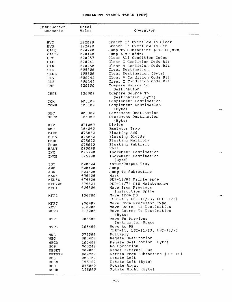
PERMANENT SYMBOL TABLE (PST)
C- 2
InstructionMnemonic OctalValue OperationBVC 102000 Branch If Overflow Is ClearBVS 102400 Branch If Overflow Is SetCALL 004700 Jump To Subroutine (JSR PC,xxx)CALLR 000100 Jump (JMP addr)CCC 000257 Clear All Condition CodesCLC 000241 Clear C Condition Code BitCLN 000250 Clear N Condition Code BitCLR 005000 Clear DestinationCLRB 105000 Clear Destination (Byte)CLV 000242 Clear V Condition Code BitCLZ 000244 Clear Z Condition Code BitCMP 020000 Compare Source ToDestinationCMPB 120000 Compare Source ToDestination (Byte)COM 005100 Complement DestinationCOMB 105100 Complement Destination(Byte)DEC 005300 Decrement DestinationDECB 105300 Decrement Destination(Byte)DIV 071000 DivideEMT 104000 Emulator TrapFADD 075000 Floating AddFDIV 075030 Floating DivideFMUL 075020 Floating MultiplyFSUB 075010 Floating SubtractHALT 000000 HaltINC 005200 Increment DestinationINCB 105200 Increment Destination(Byte)IOT 000004 Input/Output Trapimp 000100 JumpJSR 004000 Jump To SubroutineMARK 006400 MarkMED6X 076600 PDP-11/60 MaintenanceMED74C 076601 PDP-11/74 CIS MaintenanceMFPI 006500 Move From PreviousInstruction SpaceMFPS 106700 Move from PS(LSI-11, LSI-11/23, LSI-11/2)MFPT 000007 Move From Processor Typemov 010000 Move Source To DestinationMOVB 110000 Move Source To Destination(Byte)MTPI 006600 Move To PreviousInstruction SpaceMTPS 106400 Move to PS(LSI-11, LSI-11/23, LSI-11/2)MUL 070000 MultiplyNEG 005400 Negate DestinationNEGB 105400 Negate Destination (Byte)NOP 000240 No OperationRESET 000005 Reset External BusRETURN 000207 Return From Subroutine (RTS PC)ROL 006100 Rotate LeftROLB 106100 Rotate Left (Byte)ROR 006000 Rotate RightRORB 106000 Rotate Right (Byte)

PERMANENT
SYMBOL TABLE (PST)
COMMERCIAL
INSTRUCTION SET (CIS) OP CODES
Every
operation listed in the CIS table has two instruction mnemonics
.The
suffix "I", attached to every second mnemonic, indicates that the
addresses
are inline
.
The inline instructions require two arguments
;the
other instructions (excepting L2DN and L3DN) require no arguments
.
C- 3
InstructionMnemonic
OctalValue Operation
RTI 000002 Return
From Interrupt
(Permits
a trace
trap)RTS 000200 Return
From Subroutine
RTT 000006 Return
From Interrupt
(inhibits
trace trap)
SBC 005600 Subtract
Carry
SBCB 105600 Subtract
Carry (Byte)
SCC 000277 Set
All Condition Code Bits
SEC 000261 Set
C Condition Code Bit
SEN 000270 Set
N Condition Code Bit
SEV 000262 Set
V Condition Code Bit
SEZ 000264 Set
Z Condition Code Bit
SOB 077000 Subtract
One And Branch
SUB 160000 Subtract
Source From
DestinationSWAB 000300 Swap
Bytes
SXT 006700 Sign
Extend
TRAP 104400 TrapTST 005700 Test
Destination
TSTB 105700 Test
Destination (Byte)
TSTSET 007200 Test
Destination And Set Low Bit
WAIT 000001 Wait
For Interrupt
WRTLCK 007300 Read/Lock
Destination
.
Write/Unlock
R0
Into Destination
XFC 076700 Extended
Function Code
XOR 074000 Exclusive
OR
InstructionMnemonic
OctalValue Operation
ADDN 076050 Add
Numeric
ADDNI 076150 Add
Numeric
ADDP 076070 Add
Packed
ADDPI 076170 Add
Packed
ASHN 076056 Arithmetic
Shift Numeric
ASHNI 076156 Arithmetic
Shift Numeric
ASHP 076076 Arithmetic
Shift Packed
ASHPI 076176 Arithmetic
Shift Packed
CMPC 076044 Compare
Character String
CMPCI 076144 Compare
Character String
CMPN 076052 Compare
Numeric
CMPNI 076152 Compare
Numeric
CMPP 076072 Compare
Packed
CMPPI 076172 Compare
Packed
CVTLN 076057 Convert
Long To Numeric
CVTLNI 076157 Convert
Long To Numeric
CVTLP 076077 Convert
Long To Packed

* where N=0 . . .7FLOATING POINT PROCESSOR OP CODES
PERMANENT SYMBOL TABLE (PST)
C- 4
Double
InstructionMnemonic
OctalValue Operation
CVTLPI 076177 Convert Long To PackedCVTNP 076055 Convert Numeric To PackedCVTNPI 076155 Convert Numeric To PackedCVT PN 076054 Convert Packed To NumericCVTPNI 076154 Convert packed To NumericDIVP 076075 Divide DecimalDIVPI 076175 Divide DecimalLOCC 076040 Locate CharacterLOCCI 076140 Locate CharacterL2DN* 07602N Load 2 Descriptors @ (RN) +L3DN* 07606N Load 3 Descriptors @ (RN) +MATC 076045 Match CharacterMATCI 076145 Match CharacterMOVC 076030 Move CharacterM OVC I 076130 Move CharacterMOVRC 076031 Move Reverse Justified CharacterMOVRCI 076131 Move Reverse Justified CharacterMOVTC 076032 Move Translated CharacterMOVTCI 076132 Move Translated CharacterMULP 076074 Multiply DecimalMULPI 076174 Multiply DecimalSCANC 076042 Scan CharacterSCANCI 076142 Scan CharacterSKPC 076041 Skip CharacterSKPCI 076141 Skip CharacterSPANC 076043 Span CharacterSPANCI 076143 Span CharacterSUBN 076051 Subtract NumericSUBNI 076151 Subtract NumericSUBP 076071 Subtract PackedSUBPI 076171 Subtract Packed
InstructionMnemonic
OctalValue Operation
ABSD 170600 Make Absolute DoubleABSF 170600 Make Absolute FloatingADDD 172000 Add DoubleADDF 172000 Add FloatingCFCC 170000 Copy Floating Condition
CodesCLRD 170400 Clear DoubleCLRF 170400 Clear FloatingCMPD 173400 Compare DoubleCMPF 173400 Compare FloatingDIVD 174400 Divide DoubleDI VF 174400 Divide FloatingLDCDF 177400 Load And Convert From
Double To FloatingLDCFD 177400 Load And Convert From
Floating To DoubleLDCID 177000 Load And Convert Integer To

PERMANENT SYMBOL
TABLE (PST)
Instruction OctalMnemonic Value Operation
LDCIF 177000 Load
And Convert Integer To
FloatingLDCLD 177000 Load
And Convert Long
Integer
To Double
LDCLF 177000 Load
And Convert Long
Integer
To Floating
LDD 172400 Load
Double
LDEXP 176400 Load
Exponent
LDF 172400 Load
Floating
LDFPS 170100 Load
FPPs Program Status
MFPD 106500 Move
From Previous Data
SpaceMODD 171400 Multiply
And Integerize
DoubleMODF 171400 Multiply
And Integerize
FloatingMTPD 106600 Move
To Previous Data Space
MULD 171000 Multiply
Double
MULF 171000 Multiply
Floating
NEGD 170700 Negate
Double
NEGF 170700 Negate
Floating
SETD 170011 Set
Double Mode
SETF 170001 Set
Floating Mode
SETI 170002 Set
Integer Mode
SETL 170012 Set
Long Integer Mode
SPL 000230 Set
Priority Level
STAG 170005 Diagnostic
Floating Point
STBO 170006 Diagnostic
Floating Point
STCDF 176000 Store
And Convert From
Double
To Floating
STCDI 175400 Store
And Convert From
Double
To Integer
STCDL 175400 Store
And Convert From
Double
To Long Integer
STCFD 176000 Store
And Convert From
Floating
To Double
STCFI 175400 Store
And Convert From
Floating
To Integer
STCFL 175400 Store
And Convert From
Floating
To Long Integer
STD 174000 Store
Double
STEXP 175000 Store
Exponent
STF 174000 Store
Floating
STFPS 170200 Store
FPPs Program Status
STST 170300 Store
FPPs Status
SUBD 173000 Subtract
Double
SUBF 173000 Subtract
Floating
TSTD 170500 Test
Double
TSTF 170500 Test
Floating

C .2
MACRO-11 DIRECTIVES
PERMANENT
SYMBOL TABLE (PST)
The
MACRO-11 directives that follow are described in greater detail in
Appendix
B
.
Directive Function
.ASCII Translates
character string to ASCII equivalents
..ASCIZ Translates
character string to ASCII equivalents
;inserts
zero byte as last character
..ASECT Begins
absolute program section (provided for
compatibility
with other PDP-11 assemblers)
..BLKB Reserves
byte block in accordance with value of
specified
argument
..BLKW Reserves
word block in accordance with value of
specified
argument
..BYTE Generates
successive byte data in accordance with
specified
arguments
..CROSS Enables
cross-reference listing for specified
symbols ;
enables cross-reference for all symbols
..CSECT Begins
relocatable program section (provided for
compatibility
with other PDP-11 assemblers)
..DSABL Disables
specified function
..ENABL Enables
specified function
..END Defines
logical end of source program
..ENDC Defines
end of conditional assembly block
..ENDM Defines
end of macro definition, repeat block, or
indefinite
repeat block
..ENDR Defines
end of current repeat block (provided for
compatibility
with other PDP-11 assemblers)
..ERROR Outputs
diagnostic message to listing file or
command
output device
..EVEN Word-aligns
the current location counter
..FLT2 Causes
two words of storage to be generated for
each
floating-point argument
..FLT4 Causes
four words of storage to be generated for
each
floating-point argument
..GLOBL Declares
global attribute for specified symbol(s)
..IDENT Labels
object module with specified program
version
number
..IF Begins
conditional assembly block
..IFF Begins
subconditional assembly block (if
conditional
assembly block test is false)
..IFT Begins
subconditional assembly block (if
conditional
assembly block test is true)
..IFTF Begins
subconditional assembly block (whether
conditional
assembly block test is true or false)
..IIF Assembles
immediate conditional assembly statement
(if
specified condition is satisfied)
..INCLUDE Inserts
specified source file within source file
currently
being used
..IRP Begins
indefinite repeat block
;
replaces
specified
symbol with specified successive real
arguments ..IRPC Begins
indefinite repeat block
;
replaces
specified
symbol with value of successive
characters
in specified string
..LIBRARY Adds
a specified file name to a macro library list
that
is searched
.

PERMANENT
SYMBOL TABLE (PST)
Directive
Function
.LIMIT
Reserves
two words of storage for high and low
addresses
of task image
..LIST
Controls
listing level count and format of
assembly
listing
.
MACRO
denotes start of macro
definition ..MCALL
Identifies
required macro definition(s) for
assembly ..MDELETE
Deletes
the definitions of the specified macro(s)
..MEXIT
Exit
from current macro definition or indefinite
repeat
block
..NARG
Equates
specified symbol to the number of
non-keyword
arguments in the macro expansion
..NCHR
Equates
specified symbol to the number of
characters
in the specified character string
..NLIST
Controls
listing level count and suppresses
specified
portions of the assembly listing
..NOCROSS
Disables
cross-reference listing for specified
symbols ;
disables cross-reference listing for all
symbols ..NTYPE
Equates
specified symbols to the addressing mode
of
the specified argument
..ODD
Byte-aligns
the current location counter
..PACKED
Generates
packed decimal data, 2 digits per byte
..PAGE
Advances
form to top of next page
Prints
specified message on command output device
..PSECT
Begins
specified program section having specified
attributes ..RADIX
Changes
current program radix to specified radix
..RAD50
Generates
data block having Radix-50 equivalents
of
specified character string
..REM
Inserts
a block of comments into a MACRO-11 source
program
without having to precede comments lines
with
the comment character (
;) ..KEPT
Begins
repeat block and replicates it according to
the
value of the specified expression
..RESTORE
Stores
the current program section context on the
top
of the program section context stack
..SAVE
Retrieves
the program section from the top of the
.SBTTL
.TITLE
header ..WEAK
Specifies
symbols that are either defined
externally
in another module or are defined
globally
in the current module
..WORD
Generates
successive word data in accordance with
specified
arguments
.
program section context
stack
.Prints specified subtitle
text as the second line
of
the
assembly listing
page header
.Prints specified title
text as object module name
in
the
first line
of the assembly listing page


Q 26
000236 010102
Error
Code
A
APPENDIX
D
ERROR
MESSAGES
An
error code is printed as the first character in
containing
an error
.
This error code identifies the
detected
during the processing of the line
.
Example
:
MOV
R1,R2,A
The
extraneous argument A in the MOV instruction
to
be flagged with a Q (syntax) error
.
Meaning
a
source line
error
condition
above
causes the line
Assembly
error
.
Because many different conditions
produce
this error message, the directives which
may
yield a general assembly error have been
categorized
below to reflect these error
conditions :
CATEGORY
1
:
ILLEGAL ARGUMENT SPECIFIED
.
.RADIX
-- A value other than 2, 8, or 10 is
specified
as a new radix
.
.LIST/ .NLIST
-- Other than a legally defined
argument
(see Table 6-2) is specified with the
directive .
.ENABL/ .DSABL
-- Other than a legally defined
argument
(see Table 6-3) is specified with the
directive,
or the attribute arguments of a
previously
declared program section
.
.PSECT
-- Other than a legally defined argument
(see
Table 6-4) is specified with the
directive,
or the attribute arguments of a
previously
declared program section change (see
Section
6
.7 .1 .1) .
.IF/ .IIF
-- Other than
a
legally
definedconditional
test (see Table 6-6) or an illegal
argument
expression value is specified with the
directive .
.MACRO
-- An illegal or duplicate symbol found
in
dummy argument list
.

ERROR
MESSAGES
Error
Code
Meaning
A
(cont
.)
TITLE
-- Program name is not specified in the
directive,
or first non-blank character
following
the directive is a non-Radix-50
character .
.IRP/ .IRPC
-- No dummy argument is specified in
the
directive
.
.NARG/ .NCHAR/ .NTYPE
-- No symbol is specified
in
the directive
.
.IF/ .IIF
-- No
conditional
argument
isspecified
in the directive
.
CATEGORY
3
:
UNMATCHED DELIMITER/ILLEGAL ARGUMENT
CONSTRUCTION .
.ASCII/ .ASCIZ./ .RAD50/ .IDENT
-- Character string
or
argument string delimiters do not match, or
an
illegal character is used as a delimiter, or
an
illegal argument construction is used in the
directive .
.NCHAR
-- Character string delimiters do not
match,
or an illegal character is used as a
delimiter
in the directive
.
CATEGORY
4
:
GENERAL ADDRESSING ERRORS
.
This
type of error results from one of several
possible
conditions
:
1 .
Permissible range of a branch instruction
(from
-128(10) to +127(10) words) has been
exceeded .
2 .
A statement makes invalid
use
of
thecurrent
location counter
.
For example, a
" .=expression"
statement attempts to force
the
current location counter to cross
program
section (
.PSECT)
boundaries
.
3 .
A statement contains an invalid address
expression :
In
cases where an absolute address
expression
is required, specifying a global
symbol,
a relocatable value, or a complex
relocatable
value (see Section 3
.9)
results
in
an invalid address expression
.
If
an undefined symbol is made a default
global
reference by the ENABL GBL
directive
(see Section 6
.2 .1)
during passl,
any
attempt to redefine the symbol during
pass
2 will result in an invalid address
expression .

ERROR
MESSAGES
Error
Code
Meaning
A
(cont
.)
In
cases where a relocatable address
expression
is required, either a
relocatable
or absolute value is
permissible,
but a global symbol or a
complex
relocatable value in the statement
results
in an invalid address expression
.
For
example
:
.BLKB/ .BLKW/ .REPT
-- Other than an absolute
value
or an expression which reduces to an
absolute
value has been specified with the
directive .
4 .
Multiple expressions are not separated by a
comma .
This condition causes the next
symbol
to be evaluated as part of the
current
expression
.
5 .
SAVE
-- The stack is full when the
SAVEdirective
is issued
.
6 .
RESTORE
-- The stack is empty when the
.RESTORE
directive is issued
.
CATEGORY
5
:
ILLEGAL FORWARD REFERENCE
.
This
type of error results from either of two
possible
conditions
:
1 .
A global
assignment
statement(symbol==expression
or symbol==
:expres-sion)
contains a forward reference to
another
symbol
.
2 .
An expression defining the value of the
current
location counter contains a forward
reference .
B
Bounding
error
.
Instructions or word data are
being
assembled at an odd address
.
The location
counter
is incremented by 1
.
D
Doubly-defined
symbol referenced
.
Reference
was
made
to a symbol which is defined more than once
.
E
End
directive not found
.
When the end-of-file is
reached
during source input and the END directive
has
not yet been encountered, MACRO-11 generates
this
error code, ends assembly pass 1, and
proceeds
with assembly pass 2
.
Also
caused by
assembler-stack
overflow
.
In
this case MACRO-11
will
place a question mark (?) into the line at
the
point where the overflow occurred
.
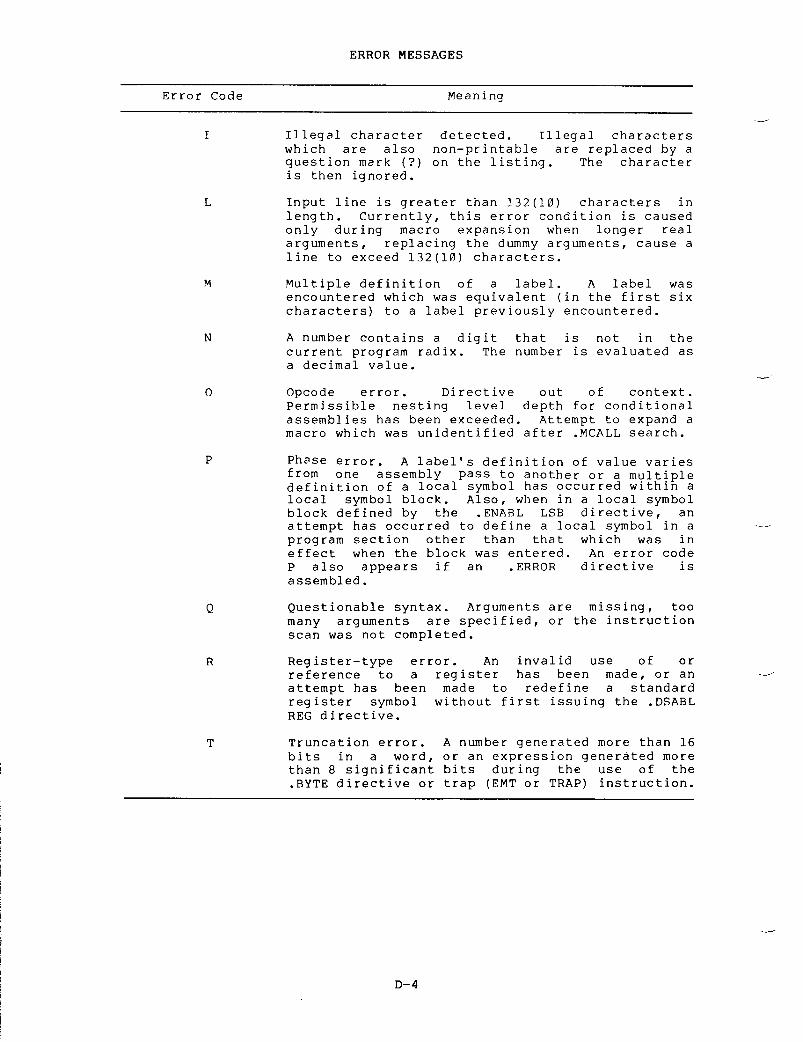
ERROR
MESSAGES
Error
Code
Meaning
I Illegal
character detected
.
Illegal characters
which
are also non-printable are replaced by a
question
mark (?) on the listing
.
The character
is
then ignored
.
L Input
line is greater than 132(10) characters in
length .
Currently, this error condition is caused
only
during macro expansion when longer real
arguments,
replacing the dummy arguments, cause a
line
to exceed 132(10) characters
.
M Multiple
definition of a label
.
A label was
encountered
which was equivalent (in the first six
characters)
to a label previously encountered
.
N A
number contains a digit that is not in the
current
program radix
.
The number is evaluated as
a
decimal value
.
0 Opcode
error
.
Directive out of context
.Permissible
nesting level depth for conditional
assemblies
has been exceeded
.
Attempt to expand a
macro
which was unidentified after MCALL search
.
P Phase
error
.
A label's definition of value varies
from
one assembly pass to another or a multiple
definition
of a local symbol has occurred within a
local
symbol block
.
Also, when in a local symbol
block
defined by the ENABL LSB directive, an
attempt
has occurred to define a local symbol in a
program
section other than that which was in
effect
when the block was entered
.
An error code
P
also appears if an ERROR directive is
assembled .
Q Questionable
syntax
.
Arguments are missing, too
many
arguments are specified, or the instruction
scan
was not completed
.
R Register-type
error
.
An invalid use of or
reference
to a register has been made, or an
attempt
has been made to redefine a standard
register
symbol without first issuing the DSABL
REG
directive
.
T Truncation
error
.
A number generated more than 16
bits
in a word, or an expression generated more
than
8 significant bits during the use of the
.BYTE
directive or trap (EMT or TRAP) instruction
.

ERROR
MESSAGES
Error
Code
Meaning
U
Undefined
symbol
.
An undefined symbol was
encountered
during the evaluation of an
expression ;
such an undefined symbol is assigned
a
value of zero
.
Other possible conditions which
result
in this error code include unsatisfied
macro
names in the list of MCALL arguments and a
direct
assigment (symbol=expression or
symbol= :expression)
statement which contains a
forward
reference to a symbol whose definition
also
contains a forward reference
;
also, a local
symbol
may have been referenced that does not
exist
in the current local symbol block
.
Z
Instruction
error
.
The instruction so flagged is
not
compatible among all members of the PDP-11
family .
See Section 5
.3
for details
.


E .1
LINE FORMAT
APPENDIX
E
SAMPLE
CODING STANDARD
Local
user requirements must be met in a coding standard, but
following
this model as closely as possible helps you and DIGITAL by
simplifying
communication and software maintenance
.
Remember that
this
is a sample and may not entirely apply to your system
.
field
should be coded in uppercase only
.
3 .
Operand field - begins in column 17 (tab stop 2)
.
This field
should
be coded in uppercase only
.
4 .
Comment field - begins in column 33 (tab stop 4)
.
If
the
operand
field extends beyond column 33 (tab stop 4) leave a
space
and start the comment
.
This field should be coded in
uppercase
and lowercase to increase readability
.
E .2
COMMENTS
To
make the program easier to understand, comments should be used to
explain
the logic behind the instructions
.
In
general this will
consist
of a comment per line of code
.
However,
if a particularly
difficult
or obscure section of code is used, precede that section
with
a longer explanation
.
Comments
that are too long for the comment field may be continued on
the
following line
.
Begin the new line with a semicolon, space over
to
the column the comment began in and continue writing
.
All comments
should
be written in uppercase and lowercase to increase readability
.
Source
lines are from one to eighty characters
following
format
:in length with the
1 .
Label Field - if present, begins in
column 1 . This fieldshould
be coded in uppercase only
.
2 .
Operation field - begins in column
9
(tab
stop 1) . This

The invert routine acceptsa list of random numbers andapplies the Kolmogorov Algorithmto alphabetize them .
E .3 NAMING STANDARDSE .3 .1 Registers
SAMPLE CODING STANDARD
If a lengthy text is needed for an explanation, begin the comment witha line containing only the characters ;+ and end it with a linecontaining only the characters ;- . The lines between these delimitersshould each begin with a semicolon and a space . For example :
E .3 .1 .1 General Purpose Registers - Use the default name :RO=%O
;REG 0Rl=$1
;REG 1R2=$?_
;REG 2R3=o3
;REG 3R4=%4
;REG 4R5=%5
;REG 5SP=%6
;Stack pointer (REG 6)PC=%7
;Program counter (REG 7)NOTE
These register names are defined withinthe assembler ; other standard symbolsmust be put in a file and linked withthe program .
E .3 .1 .2 Hardware Registers - Use the hardware
definition .
Forexample, PS (Program Status Register) and SWR (Switch Register) .
E .3 .1 .3 Device Registers - Use the hardware notation .
For example,the control status register for the RK disk is RKCS .
E .3 .2 Processor PriorityTesting or altering the processor priority is done using the symbols
PRO, PR1, PR2, . . . . . .PR7which are equated to their corresponding priority bit pattern .

E .3 .3
Symbols*
SAMPLE
CODING STANDARD
The
following chart diagrams the syntax of the 5 major types of symbol
where :
a-num
is
an alphanumeric character
.
E .3 .3 .1
Symbol Examples
Non-Global
Symbols
AlB
ZXCJl
INSRT
Global
Address Symbols
$JIM
.VECTR
$SEC
Global
Absolute Offset Symbols
A$JIM
A$XT
A .
ENT
*
Symbols that are branch targets are also called labels, but we will
always
use the term "symbol"
.
**
Number is in the range O<number<65535
.
***
The use of $ or
.
for global names is reserved for DEC-supplied
software .
E-3
names :
symbol pos-1 pos-2
pos-3
pos-4 pos-5 pos-6 length
non-global letter a-num/
a-num/
a-num/ a-num/ a-num/ >=1symbol null
null
null null null
global $/ . a-num
a-num/
a-num/ a-num/ a-num/ >=1symbol *** null
null
null null null
global letter $/ .
a-num
a-num/ a-num/ a-num/ >=3offset *** null null null
global
bit
letter a-num a-num/ a-num/
a-num/
>=4pattern *** null
null
local number $ >=2symbol **

Global
Bit Pattern Symbols
A1$20
B3 .6
JI .M
Local
Symbols
37$
271$
6$
<num>$ :
SAMPLE
CODING STANDARD
E .3 .3 .2
Local Symbols - Target symbols for branches that exist solely
for
positional reference will use local symbols of the form
Local
symbols are formatted such that the numbers proceed sequentially
down
the page and from page to page
.
E .3 .3 .3
Global Symbols - Use of global symbols is restricted, within
reason,
to those cases where reference to the code occurs external to
the
code
.
A
program never contains a GLOBL statement without showing cause
.
E .3 .3 .4
Macro Names - In a macro name the last two characters (last
character
possibly being null) have special significance
;
the next to
last
character is a $, the last character specifies the mode of the
macro .
For
example, in the three macro forms in-line, stack, and p-section,
the
in-line form has no suffix, the stack has an <S> suffix, and the
p-section
a <C>
.
Thus the Queue I/0 macro can be written as any of
QIO$
QIO$S
QIO$C
depending
on the form required
.
These are not reserved letters
.
E .3 .3 .5
General Symbols - Make frequently used bit patterns such as
carriage
return (CR) and line feed (LF) conventional symbols as they
are
needed
.

E .4
PROGRAM MODULES
There
are no limits on program size
.
However,
since the virtual
memory
capacity of a computer is finite keep programs as compact as
possible
by
:
1 .
creating them for a single function
2 .
writing them in accordance with the memory allocation
guidelines
in Appendix F
.
Code
areas are different than data areas
.
Code is read-only but data
can
be read-only or read-write
;
read-only data should be segregated
from
read-write data
.
Both areas, code and data, should have
explanatory
comments
.
E .4 .1
The Module Preface
Put
each program module in a separate file
.
For easy reference the
file
name should be similar to the name of the module
.
The file type
is
of the form 'NNN' where 'NNN' is the edit or the version number
(see
Section E
.8) .
The availability of File Control Services and File
Control
Primitives will greatly simplify version number maintenance
.
E .4 .2
The Module
Below
is a list of the information that
MACRO-11
module (see Section E
.4 .3) .
The
information is formatted as follows
:
2 .
3 .
4 .
5 .
6 .
The
first six items appear on the same page and do
explicit
headings
.
A
NLIST statement,
.NLIST/ .LIST
options
this
module, followed
.NLIST
statement has
module
edit level
.
An
IDENT statement
module
(see Section E
.8) .
SAMPLE
CODING STANDARD
A
copyright statement, and a disclaimer,
feed .
Note that the copyright,
be
all uppercase
.
This insures
presented
correctly, even on
uppercase .
is
included in the example
not
have
followed
by any
.ENABL/ .DSABL
or
that
are relevant to the assembly of
by
a matching
LIST
statement
.
Thea
comment appended to it specifying the
A
TITLE statement that specifies the name of the module
.a
module contains
are
used
.
Ifmore
than one routine, SBTTL statements
Several
SBTTL statements giving the name, general function,
and
version number of the module
.
The SBTTL directive
inserts
this information in the table of contents for quick
reference .
that
specifies
the
version number
of
the
followed
by a form
even
though a comment, should
that
the copyright will be
a
terminal that only has

SAMPLE
CODING STANDARD
7 .
The name of the facility, that the module is a part of
.
8 .
The name of the author
.
9 .
The date of module creation
.
10 .
A one or two line abstract of the function(s) of the module
.
11 .
A description of all external references made by the module,
one
per line, in alphabetical order
.
12 .
A chronological edit trail of modifications to the module
that
includes the following
:
Edit
number
Editor's
identification
Edit
date
Description
of the modification made
NOTE
Items
6 through 12 should appear on the
same
page
.
13 .
Any references to external files, using the
LIBRARY
and
.INCLUDE
directives
.
14 .
MCALL's
to any externally defined macros
.
15 .
A list of the definitions of all equated symbols used in the
module .
These definitions should appear one per line and in
alphabetical
order
.
16 .
All local macro definitions, preferably in alphabetical
order .
17 .
All local data
.
The comments in this section should include
:
Description
of each element (type, size, and so forth)
Organization
(functional, alphabetical, adjacent, and so
forth)Adjacency
requirements (if any)
18 .
A form feed, followed by an SBTTL statement describing the
routine
that follows
.
19 .
A routine header, giving the following information
:
Routine
name
DescriptionInputsCalling
sequence
OutputsSide
effects, register usage, and so forth
E-6
NOTE
Items
18 and 19 are repeated for every
routine
within the module
.

E .4 .3
Module Example
<FF>
SAMPLE
CODING STANDARD
;*
COPYRIGHT
(c) 1982, 1983
*
BY
DIGITAL EQUIPMENT CORPORATION, MAYNARD, MASS
.;*
ALL
RIGHTS RESERVED
. *
;*
THIS SOFTWARE IS FURNISHED UNDER A LICENSE AND MAY BE USED AND COPIED
;*
ONLY IN ACCORDANCE WITH THE TERMS OF SUCH LICENSE AND WITH THE
;*
INCLUSION OF THE ABOVE COPYRIGHT NOTICE
.
THIS SOFTWARE OR ANY OTHER
;*
COPIES THEREOF MAY NOT BE PROVIDED OR OTHERWISE MADE AVAILABLE TO ANY
;*
OTHER
PERSON .
N
O
TITLE TO AND OWNERSHIP OF THE SOFTWARE IS HEREBY
*
TRANSFERRED
.
;*
THE INFORMATION IN THIS SOFTWARE IS SUBJECT TO CHANGE WITHOUT NOTICE
;*
AND SHOULD NOT BE CONSTRUED AS A COMMITMENT BY DIGITAL EQUIPMENT
*
CORPORATION
.
;*
DIGITAL ASSUMES NO RESPONSIBILITY FOR THE USE OR RELIABILITY OF ITS
7 *
SOFTWARE ON EQUIPMENT THAT IS NOT SUPPLIED BY DIGITAL
.
Facility :
MACRO-11
The PDP-11 macro assembler for RT/RSX/VMS and RSTS/E
Author :
Joe
Worrall
Created :
21-Aug-82
Abstract :
MACINI
contains code only executed once per task invocation
.
Externals
Description
---------
-----------
External
file references
.LIBRARY
/MACLIB/
;Add
MACLIB
.MLB
to macro library list
.INCLUDE
/MACPRE/
;Include
MACPRE
.MAC
in assembly
$LIBID File-ID of
the system library account (LB
:[1,1))$POSID$STABF
File-IDWorkfile
of
the P/OS
statisticslibrary
account (LB
:[1,5])buffer
Edit Who Date Description
of-modification
001 Jrw 25-Aug-82-
Handle
P/OS PARSE module
.002 Jrw 05-Sep-82 Allow
recursive FINIT$'s
.003 Jrw 10-Nov-82 Setup
statistics buffer
.
.NLIST
.ENABL GBL
.LIST MEB
.LIST
.TITLE MACINI
- Once-only code for the MACRO-11 assembler
.SBTTL MACINI
- Once-only code for the MACRO-11 assembler
.SBTTL
.SBTTL IDENT
/Y05
.01/.SBTTL.IDENT /Y05 .01/
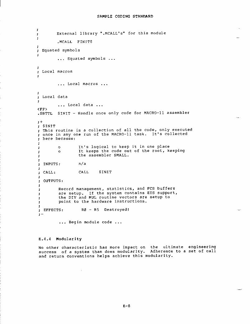
Equated
symbols
Local
macros
Local
data
External
library "
.MCALL's"
for this module
.MCALL
FINIT$
. . .
Equated symbols
.
. . .
Local macros
.
. . .
Local data
. . .
SAMPLE
CODING STANDARD
<FF>.SBTTL
$INIT - Handle once only code for MACRO-11 assembler
$INITThis
routine is a collection of all the code, only executed
once
in any one run of the MACRO-11 task
.
It's collected
here
because
:
0
o
It's
logical to keep it in one place
o
It
keeps the code out of the root, keeping
the
assembler SMALL
.
INPUTS :
n/a
CALL :
CALL $INIT
OUTPUTS :
Record
management, statistics, and FCS buffers
are
setup
.
If the system contains EIS support,
the
DIV and MUL routine vectors are setup to
point
to the hardware instructions
.
EFFECTS :
RO
- R5 Destroyed!
. . .
Begin module code
. . .
E .4 .4
Modularity
No
other characteristic has more impact on the ultimate engineering
success
of a system than does modularity
.
Adherence to a set of call
and
return conventions helps achieve this modularity
.

E .4 .4 .1
Calling Conventions (Inter-Module/Intea-Module)
Transfer
of Control
Macros
exist for call and return
.
The actual transfer is via a
JSR
PC instruction
.
For register save routines, a JSR RN,SAVE is
permitted .
Argument
Passing
The
CALL macro is
:
CALL
subr-name
The
RETURN macro is
:
RETURN
Register
Conventions
SAMPLE
CODING STANDARD
On
entry, a subroutine minimally saves all registers it intends
to
alter except result registers
.
On exit it restores these
registers .
(The preservation of the register state is assumed
across
calls
.)
Any
registers may be used, but their use should follow a coherent
pattern .
For example, if passing three arguments, use R0, Rl and
R2
rather than R0, R2, R5
.
Saving and restoring occurs in one
place .
E .4 .4 .2
Exiting - All subroutine exits occur through a single RETURN
macro .
E .4 .4 .3
Success/Failure Indication - The C bit is used to return the
success/failure
indicator, where success equals 0, and failure equals
1 .
The argument registers can be used to return values or additional
success/failure
data
.
E .4 .4 .4
Module Checking Routines - Modules are
responsible
forverifying
the validity of arguments passed to them
.
The design of a
module's
calling sequence should aim at minimizing the validity checks
by
minimizing invalid combinations
.
Programmers may add test code to
perform
additional checks during checkout
.
All code should aim at
discovering
an error as close (in terms of instruction executions) to
its
occurrence as possible
.

E .5
CODE FORMAT
E .5 .1
Program Flow
Programs
are organized on the listing so that they flow down the page,
branch
or jump
.
All unconditional branch
be
followed by a blank line
.
This causes
out
in the source code, allowing the code
even
at the cost of an extra
and
jump instructions should
these
instructions to stand
to
be traced more easily
.
For
example
:
appears
on the listing as
:
AAA :
BBB :
CMN :
TSTBNE
BBB
BR""
CMN"
SAMPLE
CODING STANDARD

rather
than
:
AAA :
CMN :
BBB :
BR
CMN
E .5 .2
Common Exits
A
common exit appears as the last code sequence on the listing
.
Thusthe
flow chart
:
appears
on the listing as
:
SAMPLE
CODING STANDARD
2 3 4
PR1 : . . . . . . . .
B EXIT
PR2 :
BR. "
EXIT
PR3 :
BR""
EXIT
PR4 :

EXIT :
and
not as
:
SAMPLE
CODING STANDARD
E .5 .3
Code with Interrupts Inhibited
Code
that is executed with interrupts inhibited, is flagged by a three
semicolon
(
; ; ;)
comment delimiter
.
For example
:
. .ERTZ :
m10$ : . . . . . . . .
e. . . .
. . . .
iii
n. . . .
. . . .
iii
t. . . .
. . . .
i
i i
E .5 .4
Code in System State
RSX-11M
executive subroutines and other privileged code that is
executed
in system state is flagged by a two semicolon (
; ;)
comment
delimiter .
For example
:
Switch
to system state,
.
PR1 : . . . . . . . .
EXIT :
PR2 :
BR""
EXIT
PR3 :
BR" .
EXIT
PR4 :
BR,"
EXIT
;Enable
by returning
;by
system subroutines,
BIS #PR7,PS inhibit
interrupts
BIT #PR7,2(SP) cBEQ 10$ oRTT

CALL
$SWSTK,EXIT
;
Inhibit context switching
; ;
Return in system state
RETURN
; ;
Go back to user state (EXIT)
EXIT :
. . .
;
User state code
E .6
INSTRUCTION USAGE
E .6 .1
Forbidden Instructions
1 .
The use of instructions or index words as literals of the
previous
instruction
.
For example
:
MOV
@PC,REGISTER
BIC
SRC,DST
uses
the bit clear instruction as a literal
.
This may seem
to
be a very "neat" way to save a word but what about
maintaining
a program using this trick? To compound the
problem,
it will not execute properly if I/D space is enabled
on
the 11/45
.
In this case @PC is a D bank reference
.
2 .
The use of the MOV instruction instead of a JMP instruction
to
transfer program control to another location
.
For
example :
MOV
#ALPHA,PC
SAMPLE
CODING STANDARD
transfers
control to location ALPHA
.
Besides taking longer
to
execute (2
.3
microseconds for MOV vs
.
1
.2
for JMP) the
use
of MOV instead of JMP makes it nearly impossible to pick
up
someone else's program and tell where transfers of control
take
place
.
What if one would like to get a jump trace of
the
execution of a program (a move trace is unheard of)? As
a
more general issue, other operations such as ADD and SUB
from
PC should be discouraged
.
3 .
The seemingly "neat" use of all single word instructions
where
one double-word instruction could be used and would
execute
faster and would not consume additional memory
.Consider
the following instruction sequence
:
CMP
-(R1)
,-(R1)
CMP
-(R1)
,-(R1)
The
intent of this instruction sequence is to subtract 8 from
register
R1 (not to set condition codes)
.
This can be
accomplished
in approximately 1/3 the time via a SUB
instruction
(9
.4
vs
.
3
.8
microseconds) at no additional cost
in
memory space
.
4 .
Self-relative address arithmetic (
.+n)
is absolutely
forbidden
in branch instructions
;
its use in other contexts
must
be avoided if at all possible and practical
.

E .6 .2
Conditional Branches
When
using the PDP-11 conditional branch instructions, it is
imperative
that the correct choice be made between the signed and the
unsigned
branches
.
SIGNED
UNSIGNED
E .7
PROGRAM SOURCE FILES
SAMPLE
CODING STANDARD
BGE
BHIS
(BCC)
BLT
BLOBGT
BHIBLE
BLOS
(BCS)
A
common pitfall is to use a signed branch (for example, BGT) when
comparing
two memory addresses
.
This works until the two addresses
have
opposite signs
;
that is, one of them goes across the 16K
(100000(8))
bound
.
This type of coding error usually results from
re-linking
the program at different addresses and/or changing the size
of
the program
.
Source
creation and maintenance is done in base levels
.
A base level
is
the point at which the program source files have been frozen
.
From
the
freeze point to the next base level, corrections are not made
directly
to the base level itself, rather a file of corrections is
accumulated
for each file in the base level
.
Whenever an updated
source
file is desired, the correction file is applied to the base
file .
The
accumulation of corrections proceeds until a logical breaking
point
has occurred (a milestone or significant implementation point
has
been reached)
.
At this time all accumulated corrections are
applied
to the previous base level to create a new base level and
correction
files are started for the new base level
.
E .8
PDP-11 VERSION NUMBER STANDARD
The
PDP-11 Version Number Standard applies to all modules, parameter
libraries
which are written as part of
effort .
It is used to provide unique
pre-released,
and in-house software
.
files,
complete programs, and
the
PDP-11 Software Development
identification
of all released,
The
version number
is
limited in that only six characters of
identification
are used
.
Future implementations of the Macro
Assembler,
linker, and librarian should provide for at least nine
characters,
and possibly twelve
.
It is expected that this standard
will
be improved as the need arises
.
Version
Identifier Format
:
<version>
<edit> <patch>
where :
<version>
consists
of two decimal digits
represent
the release number of a
The
version number starts at 00
incremented
to reflect the number
changes
in the program
.
whichprogram .and
is
of
major

These
fields are interrelated
.
When <version> is changed, then
<patch>
and <edit> must be reset to nulls
.
It is intended that when
<edit>
is incremented, then <patch> will be re-set to null, because
the
various bugs have been fixed
.
E .8 .1
Displaying the Version Identifier
The
visible output of the version identifier
ProgramName
<key-letter> <version>
.
<edit> <patch>,
where
the following Key
X
Y
V
'X'
corresponds roughly to individual
and
'V' to company support
.
The
dot
<edit>as
part
ProgramName
<space><key-letter><version>
.
<edit><patch>
Examples :
PIP
V05
.00LINK
V08
.00MACRO
V05
.00
E .8 .2
Use of the Version Number in the Program
constituentthe
first
SIN
routine,
SAMPLE
CODING STANDARD
<edit>
consists
of two decimal digits which
represent
the number of alterations made to
the
source program
.
The edit number begins
at
01 (is null if there are no edits) and is
incremented
with each alteration
.
<patch>
is
a letter between B and Z which represents
the
number of alterations made to the binary
form
of the program
.
The patch number begins
at
B (is null if there are no patches) and
changes
alphabetically with each patch
.
Letters
have been identified
:
in-house
experimental version
should
appear as
:
field
test, pre-release, or in-house release version
released
or frozen version
support,
'Y' to group support,
( .)
which separates <version> from <edit> is not used if both
and
<patch> are null
.
When a version identifier is displayed
of
program identification, then the format is
:
an
IDENT directive
.than
one module, each
number
of the program
version
numbers of the
modules ;
it
version
of a
say
V05
.01 .
is
perfectly reasonable, for example, that
new
FORTRAN library, V00, contain an existing
All
sources
must contain
the version number in
In
programs
(or libraries)
which consist of more
module
must
have a
version number
.
The version
or
library
is not
necessarily related to the

SAMPLE
CODING STANDARD
Parameter
files are also required to contain the version number in an
.IDENT
directive
.
Because the assembler records the last IDENT seen,
parameter
files must precede the program
.
Entities
which consist of a collection of modules or programs (for
example,
the FORTRAN Library) have an identification module in the
first
position
.
An identification module exists solely to provide
identification .
For example
:
;OTS
identification
.TITLE
FTNLIB
.IDENT
/V02
.00/.END
is
an identification module
.

This
appendix is intended for the MACRO-11 user who wants to avoid the
problem
of thrashing, by optimizing the allocation of virtual memory
.Users
of smaller systems should become thoroughly familiar with the
conventions
discussed herein
.
This appendix discusses the following
topics :
1 .
General hints and space-saving guidelines
2 .
Macro definitions and expansions
3 .
Operational techniques
.
The
user is assumed to have pursued a policy of modular programming,
as
advised in Appendix E
.
Modular programming results in bodies of
code
that are small, distinct and highly functional
.
Using such code,
which
presents many advantages, one can usually avoid the problem of
insufficient
dynamic memory during assembly
.
F .1
GENERAL HINTS AND SPACE-SAVING GUIDELINES
Work-file
memory is shared by a number of MACRO-11's tables, each of
which
is allocated space on demand (64K words of dynamically pageable
storage
are available to the assembler)
.
The tables and their
corresponding
entry sizes are as follows
:
1 .
User-defined symbols - five words
.
2 .
Local symbols - three words
.
3 .
Program sections - six words
.
4 .
Macro names - five words
.
5 .
Macro text - nine words
.
.
Source files - six words
.
APPENDIX
F
ALLOCATING
VIRTUAL MEMORY
In
addition, several scratch pad tables are used during the assembly
process,
as follows
:
1 .
Expression analysis - five words
.
2 .
Object code generation - five words
.

ALLOCATING
VIRTUAL MEMORY
3 .
Macro argument processing - three words
.
4 .
MCALL
argument processing - five words
.
The
above information can serve as a guide for estimating dynamic
storage
requirements and for determining ways to reduce such
requirements .
For
example, the use of local symbols whenever possible is highly
encouraged,
since their internal representation requires 25 percent
less
dynamic storage than that required for regular user-defined
symbols .
The usage of local symbols can often be maximized by
extending
the scope of local symbol blocks through the ENABL
LSB/ .DSABL
LSB MACRO-11 directives see Sections 3
.5
and 6
.2 .1) .
Since
MACRO-11 does not support a purge function, once a symbol is
defined,
it permanently occupies its dynamic memory allocation
.Numerous
instances occur during conditional assemblies and repeat
loops
when a temporarily assigned symbol is used as a count or offset
indicator .
If possible, the symbols so used should be re-used
.
In
keeping with the same principle, special treatment should be given
to
the definition of commonly used symbols
.
Instead of simply
appending
a prefix file which defines all possibly used symbols for
each
assembly, users are encouraged to group symbols into logical
classes .
Each class can then become a shortened prefix file or a
macro
in a library (see Section F
.2
below)
.
In either case, selective
definition
of symbolic assignments is achieved, resulting in fewer
defined
(but unreferenced) symbols
.
An
example of this idea is seen in the definition of IAS/RSX-11M
standard
symbols
.
The RSX system macro library, for example, supplies
several
macros used to define distinct classes of symbols
.
These
groupings
and associated macro names are as follows
:
DRERR$
- Directive return status codes
FILIO$
- File-related I/0 function codes
IOERR$
- I/0 return status codes
SPCIO$
- Special I/0 function codes
F .2
MACRO DEFINITIONS AND EXPANSIONS
Dynamic
storage is used most heavily for the storage of macro text
.Upon
macro definition or the issuance of an MCALL directive, the
entire
macro body is stored, including all comments appearing in the
macro
definition
.
For this reason, comments should not be included as
part
of the macro text
.
A librarian function switch (/SZ) is
available
to compress macro source text by removing all trailing
blanks
and tabs, blank lines, and comments
.
The system macro library
(RSXMAC .SML)
has already been compressed
.
User-supplied macro
libraries
(
.MLB)
and macro definition prefix files should also be
compressed .
For
additional information regarding these two utility
tasks,
consult the applicable RSX-11M or RSX-11M-PLUS Utilities Manual
(see
Section 0
.3
in the Preface)
.

ALLOCATING
VIRTUAL MEMORY
It
often seems practical to include a file of commonly used macro
definitions
in each assembly
.
This practice, however, may produce the
undesirable
allocation of valuable dynamic storage for unnecessary
macros .
This waste of memory can be avoided by making the file of
macro
definitions a user-supplied macro library file (see Table 8-1)
.This
means that the names of desired macros must be listed as
arguments
in the MCALL directive (see Section 7
.8),
or the automatic
MACRO
call, ENABL MCL, must be enabled (see Section 6
.2 .1) .
Certain
types of macros can be redefined to null after they have been
invoked .
This practice not only frees storage space, it also
eliminates
the overhead and the dynamic memory wasted by calling a
useless
macro
.
The practice of redefining macros to null applies
mainly
to those that define symbolic assignments, as shown in the
example
below
.
The
redefinition process may be accomplished as
follows :
Macros
exhibiting this redefinition property should be defined (or
read
via the MCALL directive) and invoked before all other macro
definition
and/or MCALL processing, a practice that ensures more
efficient
use of dynamic memory
.
F .3
OPERATIONAL TECHNIQUES
When,
despite adhering to the guidelines discussed above, performance
still
falls below expectations, several additional measures may be
taken
to increase dynamic memory
.
.MACRO
DEFIN
SYM1
= VAL1
;Define
symbolic assignments
.SYM2
= VAL2
OFF1
= SYMBOL
;Define
symbolic offsets
.OFF2
= OFF1+SIZ1
OFF3
= OFF2+SIZ2
OFFN
= OFFM+SIZM
.MACRO
DEFIN
;Macro
null redefinition
..ENDM
.ENDM
DEFIN

ALLOCATING
VIRTUAL MEMORY
The
first measure involves shifting the burden of symbol definition
from
MACRO-11 to the linker or task builder
.
In most cases, the
definition
of system I/0 and File Control Services (FCS) symbols (and
user-defined
symbols of the same nature) is not necessary during the
assembly
process, since such symbols are defaulted to global
references
(Appendix D
.1,
category 4 of error code A)
.
The linker or
task
builder attempts to resolve all global references from
user-specified
default libraries and/or the system object library
(SYSLIB) .
Furthermore, by applying the selective search option for
object
modules consisting only of global symbol definitions, the
actual
additional burden to the linker is minimal
.
The
second way is to produce only one output file (either object or
listing),
as opposed to two
.
The additional memory required to
support
the second output file is allocated from available dynamic
memory
at the start of each assembly
.

APPENDIX
G
WRITING
POSITION-INDEPENDENT CODE
G .1
INTRODUCTION TO POSITION-INDEPENDENT CODE
The
output of a MACRO-11 assembly is a relocatable object module
.
The
Task
Builder or Linker binds one or more modules together to create an
executable
task image
.
Once created, if the program is to run it must
be
loaded at the virtual address specified at link time
.
This is
because
the Task Builder or Linker has to modify some instructions to
reflect
the memory locations in which the program is to run
.
Such a
body
of code is considered position-dependent (dependent on the
virtual
addresses to which it is bound)
.
All
PDP-11 processors offer addressing modes that make it possible to
write
code that does not depend on the virtual addresses to which it
is
bound
.
Such code is termed position-independent and to run can be
loaded
at any virtual address
.
Position-independent code can improve
system
efficiency, both in use of virtual address space and in
conservation
of physical memory
.
In
multiprogramming systems like IAS, RSX-11M and RSX-11M-PLUS, it is
important
that many tasks be able to share a single physical copy of
common
code, for example, a library routine
.
To make the optimum use
of
a task's virtual address space, shared code should be
position-independent .
Position-dependent code can also be shared, but
it
must appear in the same virtual locations in every task using it
.This
restricts the placement of such code by the Task Builder or
Linker
and can result in the loss of virtual addressing space
.
The
construction of position-independent code is closely linked to the
proper
usage of PDP-11 addressing modes
.
The remainder of this
Appendix
assumes you are familiar with the addressing modes described
in
Chapter 5
.
All
addressing modes involving only register references are
position-independent .
These modes are as follows
:
R
register
mode
(R)
register
deferred mode
(R)+
autoincrement
mode
@(R)+
autoincrement
deferred mode
-(R)
autodecrement
mode
@-(R)
autodecrement
deferred mode
When
using these
position-independence,been
supplied such that they
virtual
memory location
.
addressingprovided
are
modes,
you are guaranteed
the
contents of the registers have
not
dependent upon a particular

WRITING
POSITION-INDEPENDENT CODE
The
relative addressing modes are position-independent when a
relocatable
address is referenced from a relocatable instruction
.These
modes are as follows
:
A
relative
mode
@A
relative
deferred mode
Relative
modes are not position-independent when an absolute address
(that
is a non-relocatable address) is referenced from a relocatable
instruction .
In this case, absolute addressing (@#A) may be used to
make
the reference position-independent
.
Index
modes can be either position-independent or position-dependent,
according
to their use in the program
.
These modes are as follows
:
N=4
X(R)
index
mode
index
deferred mode
@X
(R)
If
the base, X, is an absolute value (for example, a control block
offset),
the reference is position-independent
.
For example
:
MOV
2(SP),RO
;Position-independent
MOV
N(SP),RO
;Position-independent
If,
however, X is a relocatable address, the reference is
position-dependent .
For example
:
G .2
EXAMPLES
CLR
ADDR(R1)
;Position-dependent
Immediate
mode can be either position-independent or not, according to
its
usage
.
Immediate mode references are formatted as follows
:
#N
immediate
mode
When
an absolute expression defines the value of N, the code is
position-independent .
When a relocatable expression defines N, the
code
is position-dependent
.
That is, immediate mode references are
position-independent
only when N is an absolute value
.
Absolute
mode addressing is position-independent only in those cases
where
an absolute virtual location is being referenced
.
Absolute mode
addressing
references are formatted as follows
:
@#A
absolute
mode
An
example of a position-independent absolute reference is a reference
to
the directive status word ($DSW) from a relocatable instruction
.For
example
:
MOV
@#$DSW,RO
;Retrieve
directive status
The
RSX-11M library routine, PWRUP, is a FORTRAN callable subroutine
that
establishes or removes a user power failure Asynchronous System
Trap
(AST) entry point address
.
Imbedded within the routine is the
AST
entry point that saves all registers, effects a call to the
user-specified
entry point, restores all registers on return, and
executes
an AST exit directive
.
The following examples are excerpts
G- 2

from
this routine
.
The first example, Figure G-1 has been modified to
illustrate
position-dependent references
.
The second example, Figure
G-2,
is the position-independent version
.
Position
dependent code example
PWRUPtt
CLR
-(SP)
;Assume
success
Perform
further initialization
. . .
loft
20fi;
Continue Processing
. . .
AST
service routine
WRITING
POSITION-INDEPENDENT CODE
BA :
MOV
ROr-(SP)
;Preserve
RO
Rest
of routine follows
. . .
20f
t
Figure
G-1 Example of Position-Dependent Code
Position
independent code example
PWRUPtt
CLR
-(SP)
;Assume
success
Perform
necessarw initialization
. . .
loft
Continue
Processing
. . .
AST
service routine
BA :
MOV
ROr-(SP)
;Preserve
RO
;
Rest of routine follows
. . .
Figure
G-2 Example of Position-Independent Code
G- 3
MOV Q "$OTSVPR4 ;Point
R4 at object time swstem save area
1
the above reference to $OTSV is Position-
;
independent
MOV (SP)+PR2 ;Retrieve
AST entry Point address
BNE 10f ;Branch
if one was specified
CLR -(SP) ;If
noner specify no Power fail routine
BR 20f ;Bwpass
AST setup
MOV R2FF .PF(R4) ;Set
the AST entry Point
MOV PCP-(SP) ;Push
our PC to relocate our AST service addr
ADD #BA- .r(SP) ;Relocate
our AST service address now
the
above reference to BA is Position-
;
independent
;
this costs one word to relocate
MOV SOTSVPR4 ;Point
R4 at object time swstem save area
the
above reference to $OTSV is Position-
;
dependent
MOV (SP)+PR2 ;Retrieve
AST entry Point address
BNE 1Of ;Branch
if one was specified
CLR -(SP) ;If
noner specify no Power fail routine
BR 20f ;Bwpass
AST setup
MOV R2pF .PF(R4) ;Set
the AST entry Point
MOV #BAr-(SP) ;Push
our AST service address
the
above reference to BA is Position-
;
dependent

WRITING
POSITION-INDEPENDENT CODE
The
position-dependent version of the subroutine contains a relative
reference
to an absolute symbol ($OTSV) and a literal reference to a
relocatable
symbol (BA)
.
Both references are bound by the Task
Builder
to fixed memory locations
.
Therefore, the routine will not
execute
properly as part of a resident library if its location in
virtual
memory is not the same as the location specified at link time
.
In
the position-independent version, the reference to $OTSV has been
changed
to an absolute reference
.
In addition, the necessary code has
been
added to compute the virtual location of BA based upon the value
of
the program counter
.
In this case, the value is obtained by adding
the
value of the program counter to the fixed displacement between the
current
location and the specified symbol
.
Thus, execution of the
modified
routine is not affected by its location in the image's
virtual
address space
.
The
MACRO-11 Assembler provides a way of checking whether the code is
position-independent .
In an assembly listing, MACRO-11 inserts a '
character
following the contents of any word which requires the Task
Builder
or Linker to perform a relocation operation and, therefore,
may
not be position independent code
.
The
cases which cause an
apostrophe
to be inserted in the assembly listing are as follows
:
1 .
Absolute mode references when the reference is relocatable
.References
are not flagged when they are absolute
.
For
example :
MOV
@#ADDR,RI
;Pic
only if ADDR is absolute
.
2 .
Index and index deferred mode references when the offset is
relocatable .
For example
:
MOV
ADDR(Rl),R5
;Non-pic
if ADDR is relocatable
.MOV
@ADDR(R1),R5
;Non-pic
if ADDR is relocatable
.
3 .
Relative and relative deferred mode references when the
address
specified is relocatable with respect to another
program
section
.
For example
:
MOV
ADDRI,R1
;Non-pic
when ADDR1 is absolute
.MOV
@ADDR1,R1
4 .
Immediate mode references to relocatable addresses
.
MOV
#ADDR,Rl
;Non-pic
when ADDR is relocatable
.
In
one case, MACRO-11 does not flag a potential position-dependent
reference .
This occurs where a relative reference is made to an
absolute
virtual location from a relocatable instruction (see the MOV
$OTSV,R4
instruction in Figure G-1)
.
References
requiring more than simple relocation at link time are
indicated
in the assembly listing
.
Simple global references are
flagged
with the letter G
.
Statements which contain multiple global
references
or require complex relocation, are flagged with the letter
C
(see Section 3
.9
and Chapter 4)
.
It
is difficult to positively
state
whether or not a C-flagged statement is position-independent
.However,
in general, position dependence can be decided by applying
the
guidelines discussed earlier in this Appendix to the resulting
address
value produced at link time
.
G- 4

APPENDIX
H
SAMPLE
ASSEMBLY AND CROSS REFERENCE LISTING
>RSOUNP
MACRO V05
.00
Saturday OB-Jan-83 11
:47TABLE
OF CONTENTS
2-
1
RAD50
unpack
.
routine
R50UNP MACRO
V05
.00
Saturday 08-Jan-83 11
:47
Pase 1
1 TITLE
R50UNP
2 IDENT
/02/
34 i
i
COPYRIGHT (c) 1979 BY
6 DIGITAL
EQUIPMENT CORPORATION
.
MAYNARD, MASS
.7 i8 i
THIS SOFTWARE IS FURNISHED UNDER A LICENSE AND MAY BE USED AND COPIED
9 i
ONLY IN ACCORDANCE WITH THE TERMS OF SUCH LICENSE AND WITH THE
10 i
INCLUSION OF THE ABOVE COPYRIGHT NOTICE
.
THIS SOFTWARE OR ANY OTHER
11 +
COPIES THEREOF MAY NOT BE PROVIDED OR OTHERWISE MADE AVAILABLE TO ANY
12 i
OTHER
PERSON .
N
O
TITLE TO AND OWNERSHIP OF THE SOFTWARE IS HEREBY
13 :
TRANSFERRED
.1415 i
THE INFORMATION IN THIS SOFTWARE IS SUBJECT TO CHANGE WITHOUT NOTICE
16 i
AND SHOULD NOT BE CONSTRUED AS A COMMITMENT BY DIGITAL EQUIPMENT
1.7 i
CORPORATION
.1819 DIGITAL
ASSUMES NO RESPONSIBILITY FOR THE USE OR RELIABILITY OF ITS
20 i
SOFTWARE ON EQUIPMENT WHICH IS NOT SUPPLIED BY DIGITAL
.1
22 i
UPDATE HISTORY
:24 D .N .
CUTLER 10-FER-73
25 f

SAMPLE
ASSEMBLY AND CROSS REFERENCE LISTING
H- 2
14 000000 PSECT PUREIPI1516 000000 010446 R50UNP : :MOV R4,-(SP) ;Save
R4
17 000002 012704 MOV 0$YMBOLYR4 ;Point
at RAD50 symbol buffer
OOOOOOG18 000006 012401 1t :
MOV
(R4)+ .R1 ;Get
next RAD50 word
19 000010 012703 MOV 050*50,R3 ;Set
divisor for high character
00310020 000014 004767 CALL 10$ ;Unpack
and store the character
00003021 000020 012703 MOV 050,R3 ;Now
set divisor for middle character
00005022 000024 004767 CALL 104 ;Unpack
and store the character
00002023 000030 010100 MOV R1,RO ;Copy
remaining character
24 000032 004767 CALL llf ;Translate
and store it
00001625 000036 020427 CMP R4r0SYMBOL+4 ;Test
if last word done
000004G26 000042 001361 BNE 1t ;Branch
if no
27 000044 012604 MOV (SP)++R4 :Restore
R4
.'B 000046 000207 RETURN ;Return
to caller
2930 ;
Divide RA1150 word and convert char to ASCII
3132 000050 005000 10f :
CLR
RO33 000052 071003 DIV R3,RO3435 ;
Translate RAD50 character code to ASCII
36 ;
0 = space
37 i
1-32 = A-Z
38 ;
33 = f
39 ;
34 =
40 ;
35 = unused code
41 i
36-47 = 0-9
4243 000054 005700 ll$ :
TST
RO ;Test
if space
44 000056 001412 BEG 23$ ;Branch
if so
45 000060 020027 CMP ROr033 ;Test
if middle
00003346 000064 002405 BLT 22f ;Branch
if alphabetic
47 000066 001402 BEG 21$ ;Branch
if dollar sign
48 000070 062700 ADD 022-11,RO ;Dot
or digits 0-9
000011
R50UNP
MACRO V05
.00RAD50
UNPACK ROUTINE
1
Saturday
08-Jan-83 11
:47
Page 2
SBTTL
RAD50 unpack routine
3 i+4 i
R50UNP
5 i
Unpack a 6 char RAD50 symbol to ASCII
6 i7 i
Enter with R2 -
."
Output ASCII string
8 i
SYMBOL
.
SYMBOL+2 = RAD50 symbol to unpack
410 i
Return with R2 -
;"
Past output string
11 i
R0
.
Rlr R3 Destroyed
12 ;-13
R50UNP MACRO V05 .00 Saturday 08-Jan-83 11 :47
Page
2-1RAD50
UNPACK ROUTINE
49 000074 062700 21$ : ADD 011-100+RO ;Dollar177711
50 000100 062700 229 : ADD 0100-40YRO ;Alphabetic000040
51 000104 062700 23E : ADD 040,80 :Space000040
52 000110 110022 MOVE R0+(R2)+ ;Store
ASCII char in buffer
53 000112 000207 RETURN5455 000001 END
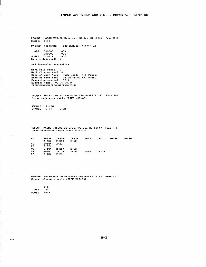
.
ASS
.
000000
000000000
001
PUREI
000114 002
Errors
detected
:
0
***
Assembler statistics
R50UNP
2-16*
SYMBOL
2-17 2-25
0-0.
ASS
.
0-0
PUREI
2-14
SAMPLE
ASSEMBLY AND CROSS REFERENCE LISTING
R50UNP
MACRO 1105
.00
Saturday 08-Jan-83 11
:47
Pase 2-2
Symbol
Table
R50UNP
OOOOOORG
002
SYMBOL= ****** GX
Work
file reads
:
0
Work
file writes
:
0
Size
of work file
:
7936 Words ( 1 Pases)
Size
of core Pool
:
16158 Words (72 Pases)
Operatins
system
:
RT-11Elapsed
time
:
00
:00 :04 .34DK :R50UNP .DK :R50UNP/C=DK :SUM
R50UNP
MACRO 1105
.00
Saturday 08-Jan-83 11
:47
Pase S-1
Cross
reference table (CREF 1105
.00)
R50UNP
MACRO 1105
.00
Saturday 08-Jan-83 11
:47
Pase C-1
Cross
reference table (CREF 1105
.00)
R50UNP MACRO
1105
.00
Saturday
08-Jan-83 11 :47 Pase
R-1
Cross reference table (CREF
1105
.00)
RO 2-23* 2-32* 2-33* 2-43 2-45 2-48* 2-49*2-50* 2-51* 2-52
R1 2-18* 2-23R2 2-52*R3 2-19* 2-21* 2-33R4 2-16 2-17* 2-18 2-25 2-27*SP 2-16* 2-27


APPENDIX
I
OBSOLETE
MACRO-11 DIRECTIVES, SYNTAX, AND COMMAND LINE OPTIONS
I .1
OBSOLETE DIRECTIVES AND SYNTAX
The
following directives and syntax, although supported in this
release
of the assembler, will NOT be supported in future assembler
releases .
The following table shows the old directives and syntax,
and
the new syntax to use
.
All MACRO-11 code that contains the old
directives
and syntax should be updated to use the new syntax
.
1 .2
OBSOLETE COMMAND LINE OPTION
Table
I-1
Old
and New Directives and Syntax
The
MACRO-11 command line option /P[ASS]
:n
is no longer supported by
DIGITAL .
This switch was originally created to speed up assemblies in
some
cases by only scanning a given file with one pass of the
assembler .
It
has been found that the /P[ASS]
:nhas
caused more problems than can be documented reasonably
.switch
has many side effects, and
Although
the syntax of the /P[ASS]
:n
switch is still allowed to
on
a MACRO-11 command line, no SPRs will be accepted relating
switch .
All documentation for the /P[ASS]
:n
switch has been removed
.
appearto
the
Any
assembly command files containing the /P[ASS]
:n
switch should be
updated
by removing this switch
.
Syntax
no longer supported
New
syntax to use
.
EOT
None.IFZ
xxx or
.IFEQ
xxx
.IF
EQ,xxx
.IF
Z,xxx
.IF
EQ,xxx
.IFNZ
xxx or
.IFNE
xxx
.IF
NE,xxx
.IF
NZ,xxx
.IF
NE,xxx
.IFL
xxx or
.IFLT
xxx
.IF
LT,xxx
.IF
L,xxx
.IF
LT,xxx
.IFG
xxx or
.IFGT
xxx
.IF
GT,xxx
.IF
G,xxx
.IF
GT,xxx
.IFLE
xxx
.IF
LE,xxx
.IFDF
xxx
.IF
DF,xxx
.IFNDF
xxx
.IF
NDF,xxx


APPENDIX
J
RELEASE
NOTES
This
appendix explains the changes that have been made to MACRO-11
since
the last version release
.
The new features mentioned are fully
documented
in chapters one through nine of this manual
.
J .1
CHANGES -- ALL VERSIONS OF MACRO-11
1 .
The opcode, CALLR addr (Call-Return), has been added to the
permanent
symbol table (PST)
.
This opcode is equivalent to
the
JMP addr opcode
.
The CALLR addr opcode was added to
complement
the CALL addr opcode -- which is equivalent to the
JSR
PC,addr opcode
.
2 .
The previous version of MACRO-11 used a range of 64$ to 127$
for
automatic local symbol generation
.
MACRO-11 now uses a
range
of 30000$ to 65535$ when generating local symbols
.
3 .
Most assembler generated listing text is now in
upper/lowercase .
This change was made to increase the
readability
of MACRO-11 code
.
Lines of code that include the
.SBTTL
or the TITLE directive are not converted to
uppercase .
4 .
Lines of code that include the SBTTL directive are listed in
the
table of contents of an assembly listing, even if a
.NLIST
statement is in effect at the time the
SBTTL
lines
are
encountered
.
You
may specify the NLIST directive with
the
TOC argument to prevent the table of contents from being
printed .
5 .
The symbol table is printed at the end of an assembly, even
if
the NLIST directive is in effect
.
You may specify the
.NLIST
directive with the SYM argument to prevent the symbol
table
from being printed
.
6 .
All page headers include the day of the week
.

RELEASE
NOTES
7 .
The assembler statistics information that appears at the end
of
the assembly listing file has been updated to include the
following
additional information
:
Total
number of virtual work file reads
Total
number of virtual work file writes
Maximum
amount of virtual memory used (in words and pages)
Size
of physical memory freespace (in words and pages)
Operating
system and environment that the assembler is
running
under
Total
elapsed assembly time
MACRO-11
command line
8 .
The PSECT synopsis that is printed in the listing file, after
the
symbol table, includes the psect attributes
.
9 .
The maximum number of relocatable terms in a complex
expression
has been changed
.
The maximum size of an OBJ
record
that MACRO-11 can produce was increased from 42
.
bytes
to
128
.
bytes
.
Do
not compare OBJ files that have been created by different
versions
of MACRO-11 when verifying whether your code
generation
is correct
.
Changes that have been made for this
version
of MACRO-11 (mentioned above) will invalidate a
direct
comparison of assembler OBJ output
.
Verify code
generation
by linking or taskbuilding the OBJ files involved
and
then comparing the SAV or the TSK image files
.
Because
the OBJ files produced by this new version
of
MACRO-11 are different, users of the PAT (object
file
patch utility) are warned that checksums must be
recomputed
on any object patches assembled with this
new
version of MACRO-11
.
10 .
The default for the LC argument has been changed from
DSABLLC
to ENABL LC
.
11 .
The following
.ENABL/ .DSABL
options have been added
:
1 .
ENABL
LCM/
.DSABL
LCM
2 .
ENABL
MCL/
.DSABL
MCL
12 .
The following directives have been added to MACRO-11
.
Thesenew
directives are documented in this manual
.
1 .
CROSS
2 .
INCLUDE
3 .
LIBRARY
4 .
MDELETE
5 .
NOCROSS
6 .
REM
7 .
WEAK
J-2
NOTE

1 .
The message
:
Errors
detected
:
0
RELEASE
NOTES
J .2
CHANGES -- MACRO-11/RSX VERSION ONLY
1 .
The cross-reference options SEC and ERR have been added
.
NOTE
The
RSX-11 CREF program (CRF) has been updated to
include
support for these two new macro
cross-reference
options
.
Only the new RSX-11 CRF
version
(V2) distributed with RSX-11M V4
.1
and
RSX-11M-PLUS
V2
.1
should be used with this version of
MACRO-11 .
2 .
The default for the command line option /[-]SP has been
modified
from /SP to /-SP
.
The new default may be modified
by
the system manager using the TKB GBLPAT option described
in
the MACRO-11/RSX task build command file
.
J .3
CHANGES -- MACRO-11/RT-11 VERSION ONLY
has
been removed
.
MACRO-11
prints this message on the
terminal
only if errors have been detected in the module
2 .
the
RSX-11 version of MACRO-11
.
3 .
RSX-11 style command line switches may be used in addition to
the
one-character switches
:
4 .
The default file extension for macro libraries has been
changed
to MLB, to conform with RSX-11
.
The RT-11 V5 LIBR
program
defaults its macro library output to the MLB
extension
also
.
/M may be represented as /M[LIB]/E may be represented as /E[NABL]/D may be represented as /D[SABL]/P may be represented as /P[ASS]/L may be represented as /L[IST]/N may be represented as /N[LIST]
being
assembled
.
If
the first character
in a
MACRO-11/RT-11 command line is a
semicolon
(
;),
the
line is
treated as a comment and is
ignored .
This change
was made
to maintain compatibility with

RELEASE
NOTES
5 .
Prior to this release of MACRO-11, if you specified more than
one
MLB file on a command line, and each file had a
definition
of the same macro, the first macro library
specified
would be used for the macro definition if called in
the
source program
.
This has been modified to work like the
RSX-11
macro assembler
.
The RT-11 macro assembler now scans
.MLB
files from the last file specified (either in the
MACRO-11
command line or by using the LIBRARY directive) to
the
first file specified
.
The assembler then scans the
system
default macro library, SY
:SYSMAC .SML .
6 .
The default for the GBL argument has been changed from DSABL
GBL
to ENABL GBL
.

INDEX
6-16,
6-49, 8-10, 8-12,
Character
set
D-3
ASCII,
A-1 to A-3
pass
2, 1-2, 6-12, 6-21, 7-15,
legal,
3-1 to 3-3
D-3
Radix-50,
A-5, A-6
Assignment
operator
.
See Direct
CLR
instruction, G-3, G-3, H-2
assignment
operator
CMP
instruction, E-13, H-2
Assignment
statement
.
See Direct
Coding
standard, E-1
assignment
statement
Comment,
E-1, E-5
Autodecrement
deferred mode, 5-1,
delimiter,
3-2, B-1, E-12
5-5,
B-2, G-1
field,
2-1, 2-4, 2-5, E-1
Autodecrement
indicator, 3-2
Commercial
instruction set, C-3
Autodecrement
mode, 5-1, 5-4,
Common
exit, E-11
B-1,
B-2, G-1
Complex
relocatable expression,
Autoincrement
deferred mode, 5-1,
3-185-4,
B-2, G-1
Complex
relocation, 4-1, G-4
Index- 1
A
error, 3-10, 3-13, 5-10, 6-15,
6-25,
6-26, 6-28, 6-2
.9,
6-32,
6-33,
6-38, 6-40, 6-42
.
6-44,
6-47,
6-56, 7-2, 7-12 to 7-14,
7-16,
7-17, 7-20
Autoincrement
indicator, 3-2
Autoincrement
mode, 5-1, 5-3,
B-2,
G-1
Absolute
address, D-2
Base
level, E-14
Absolute
binary output, 6-19
BCC
instruction, E-13
Absolute
expression, 3-17
BCS
instruction, E-14
Absolute
mode, 5-1, 5-7,
BEQ
instruction, H-2
B-2,
G-2, G-4
BGE
instruction, E-13
Absolute
module, 6-42
BGT
instruction, E-14
Absolute
program section, 6-42 to
BHI
instruction, E-14
6-45,
B-4
.
See also ASECT
BHIS
instruction, E-13
directive BIC
instruction, E-13
ADD
instruction, E-12, G-3
;
H-2
Binary
operator, 3-4, 3-5, 3-16
Addition
operator, 3-2, 3-5, B-1
Blank
line, 2-1
Address
boundaries, 6-39
BLE
instruction, E-14
Addressing
modes, 5-1
BLKB
directive, 3-14, 6-2, 6-36
Apostrophe,
G-4
to
6-38, B-4, D-3
ASCII BLKW
directive, 3-14, 6-2, 6-36,
character
set, A-1
6-38,
6-48, B-4, D-3
conversion
characters, 6-23 to
BLO
instruction, E-13
6-26 BLOS
instruction, E-13
.ASCII
directive, 6-1, 6-21, 6-26
BLT
instruction, E-13, H-2
to
6-28, 6-36, B-3
BNE
instruction, E-10, G-3, H-2
.ASCIZ
directive, 6-1, 6-28,
BR
instruction, E-10, E-11, G-3
6-36,
B-4
Branch
instruction
.ASECT
directive, 3-11, 3-13,
addressing,
5-9, D-2
3-14, 6-2,
6-44 to 6-47, B-4
use
of, E-13
Assembler directives .
See Permanent
BYTE
directive, 6-2, 6-23,
6-36,symbol table B-4,
D-4
version number,
6-4
Assemblyerror . See
A error
C
bit, E-9
listing symbols,
4-1
CALL
instruction, H-2
pass
1,
1-1,
1-2, 6-12, 6-15,
Calling
convention, E-8

INDEX
B-4,
B-5
B-5Conditional
assembly directive,
Expression,
evaluation of, 3-16
6-49
Expression
indicator, immediate,
Copyright
statement, E-5
3-2,
B-1
.CROSS
directive, 6-2, 6-22,
External
expression, 3-17
B-4,
C-5
External
symbol, 6-52
.
See also
Cross-reference
listing, 3-12,
Global
symbol
6-19,
8-8, 8-9, 8-14, 8-16 to
8-18,
9-2, 9-3, 9-5 to 9-7
Data
Floating-point
truncation, 6-19,
sharing,
6-45
6-35storage,
6-2
FLT2
directive, 6-2, 6-35, B-5
storage
directives, 6-23
FLT4
directive, 6-2, 6-35, B-5
Default
radix, 3-14
FLX,
6-19
Default
register definitions,
Forbidden
instructions, E-13
3-10,
6-21
Format
control, 2-5
Deferred
addressing indicator,
Formatted
binary, 6-19
3-2,
B-1
FORTRAN,
6-47, E-15, G-2
Delimiting
characters, 3-3, 6-17,
Forward
reference, 3-8, 3-9,
6-29,
B-3 to B-5, B-8
3-10,
3-13, D-4
Device
register, E-2
illegal,
D-3
Direct
assignment
Function
control switches
.
See
operator,
3-1, 3-2, 3-9, B-1
Switches,
function control
statement,
3-6 to 3-9, 3-13,
Function
directive, 6-18
6-37Directives .
See Permanent
symbol
table
Global
expression evaluation,
DIV
instruction, H-2
3-17Division
operator, 3-2, 3-5, B-1
Global
label, 6-51
Double
ASCII character indicator,
Global
reference, 6-21, 6-51,
3-2,
B-1
F-4,
G-4
.DSABL
directive, 6-2, 6-19 to
Global
symbol, 1-2, 3-7, B-5,
6-21,
8-6, 8-8, 9-4, B-4,
D-2,
D-3, E-4
D-1
Global
symbol definition, 2-2,
Dummy
argument, 7-2, 7-11, 7-17
3-1,
3-2, 3-8, 6-51
.
See
also
GLOBL directive
Global
symbol directory, 1-2
E
error, 6-40
GLOBL
directive, 3-7, 6-2, 6-51,
EMT
instruction, 5-9, D-4
B-5,
E-4
.ENABL
directive, 6-2, 6-19 to
6-21,
8-6, 8-8, 9-4, B-4,
D-1,
D-2, D-4, F-2
Hardware
register, E-2
.END
directive, 6-2, 6-40, B-4,
D-3,
H-2
.ENDC
directive, 6-2, 6-12, 6-53
I
error, 6-28
;
6-30
to
6-56, 6-59, 7-3, B-4
IAS,
6-48, 7-21, 8-14 to 8-17,
.ENDM
directive, 6-13, 6-21, 7-2,
8-19
to 8-22, G-1
7-3,
7-6 to 7-8, 7-10, 7-11,
IDENT
directive, 6-2, 6-16, B-5,
7-17
to 7-19, B-4, B-8, F-3
D-2,
E-5, E-7, E-15, H-1
Index-2
.CSECT
directive, 3-11, 3-13,
Field
terminator, 3-2, B-1
6-2,
6-44 to 6-47, 9-6, B-4
Current
location counter, 2-2,
3-2,
3-12 to 3-14, 3-17, 5-8,
FILES-11,
6-19
Floating-pointSee
also
directives,
B-5
.FLT2
directive
6-11,
6-36 to 6-38, 6-43 to
Floating-point indicator,
B-3
6-44,
B-5, B-7, D-2, D-3
Floating-point processor,
3-14,
6-34,
6-35,
C-4Floating-point rounding,
6-3
.9,D
error, 2-3
6-32
Concatenation
indicator, 3-3,
B-1,
B-3
ENDR
directive, 7-19, 7-20, B-5,
B-8Conditional
assembly, 6-51 to
Entry
point symbol, 6-52
6-56,
7-8, 7-16, D-4
ERROR
directive, 7-16, B-5, D-4
immediate,
6-56
Error
messages, D-1 to D-5
Conditional
assembly block, 7-3,
EVEN
directive, 6-2, 6-29, 6-38,

INDEX
.IF
directive, 6-2, 6-12, 6-53 to
LIST
directive, 6-3, 6-9 to
6-59,
7-3, 7-8, B-5, D-1, D-2
6-14,
6-21, 8-6, 8-11,
.IFF
directive, 6-2, 6-56 to
8-13,
9-4, B-6, D-1
6-58,
B-5
Listing
control, 6-4 to 6-14
..IFT
directive, 6-2, 6-56 to
See
also LIST directive,
6-58,
B-5
NLIST
directive
.IFTF
directive, 6-2, 6-56, 6-57,
Listing
control switches
.
See
B-6
Switches,
listing control
.IIF
directive, 6-2, 6-59, B-6,
Listing
level count, 6-9, 6-10,
D-1,
D-2
6-12,
B-6, B-7
Illegal
characters, 3-3, D-2, D-3
Local
symbol, 3-11, 3-12, 7-8,
Illegal
forward reference, D-3
7-9,
D-4, E-4, F-2
Immediate
conditional assembly,
Local
symbol block, 3-11, 3-12,
6-59
6-20,
D-4, F-2
Immediate
expression indicator,
Location
counter
.
See Current
3-2,
B-1
location
counter
Immediate
mode, 5-1, 5-6, B-2,
Location
counter control, 6-34 to
G-2,
G-4
6-36Implicit
WORD directive, 2-1,
Logical
AND operator, 3-2, 3-5,
2-4,
6-25
6-55,
B-1
.INCLUDE
directive, 6-2, 6-61,
Logical
inclusive OR operator,
9-8,
B-6, C-6
3-2,
3-5, 6-55
Indefinite
repeat block
.
See
Logical
OR operator, B-1
Repeat
block, indefinite
Index
deferred mode, 5-1, 5-5,
B-2,
G-2, G-4
M
error, 2-3, 3-1, 3-2, 3-8
Index
mode, 5-1, 5-5, 5-7, B-2,
MacroG-2,
G-4
argument,
7-7, 7-14, 7-15, B-3
Initial
argument indicator, 3-2,
argument
concatenation, 7-11
B-1
attribute
directive, 7-12
Initial
expression indicator, 3-2
definition,
6-33, 7-1 to 7-13,
Initial
register indicator, 3-2,
7-15,
7-17, 7-18, 7-20, B-4,
B-1
B-6 .
B-7
.
E-6
.
F-2
Instruction
set
directive,
7-1, 7-2, 7-4
.
See
commercial,
C-3
also
MACRO directive
PDP-11,
C-1
expansion,
7-1, 7-3, 7-5 to
Interrupts,
E-12
7-7,
7-9, 7-11, 7-17, B-7,
.IRP
directive, 7-2, 7-17 to
D-4,
F-2
7-19,
B-6, D-2
expansion
listing, 6-9, 6-12
.IRPC
directive, 7-2, 7-17 to
keyword
argument, 7-4, 7-10
7-19,
B-6, D-2
keyword
indicator, 3-1
Item
terminator, 3-2, B-1
name,
7-1, 7-2, 7-4, D-4, E-4
nesting,
7-2, 7-3, 7-6, 7-17
numeric
argument, 7-7
JMP
instruction, 5-3, E-13
redefinition,
F-3
JSR
instruction, 5-3, E-9
symbol,
3-6
Macro
call, 7-1, 7-4 to 7-11,
7-12,
7-20, B-1, B-6
.
See
L
error, 2-1
also
MCALL directive
Label
Macro
call argument, 7-4
field,
2-1 to 2-3, E-1
Macro
call numeric argument, 3-3
multiple
definition, 2-3
MACRO
directive, 6-13, 6-21, 7-1
terminator,
3-1, B-1
to
7-9, 7-10, 7-11, 9-6, B-6,
.LIBRARY
directive, 6-2, 6-60,
D-1,
F-3
9-9,
B-6, C-6
Macro
library directive
.
See
.LIMIT
directive, 6-3, 6-39, B-6
MCALL
directive
Line
format, E-1
Macro
symbol table, 3-6, 3-7
Line
printer listing format, 6-5,
MACRO-11
character set
.
See
6-6,
6-12
.
See also Listing
Character
set, legal
control
MCALL
directive, 7-20, 8-6,
Linker,
1-2, 2-2, 6-17, 6-43,
8-15,
9-5 to 9-6, B-6,
6-47,
6-51, F-4, G-1, G-4
D-4,
F-1 to F-3
Linking,
4-1, 6-40
MDELETE
directive, 7-21, B-7, C-7
Index-3

INDEX
Memory
Pageallocation,
6-42, 6-47, F-1,
header,
6-4
F-2
number,
6-17
conservation,
F-1
Patch,
E-15
.MEXIT
directive, 7-3, 7-18 to
Permanent
symbol table, C-1 to
7-20,
B-7
C-3,
3-6, 3-7
Modularity,
6-44, E-8, F-1
Position-independent
code, G-1 to
Module
checking routine, E-9
G-4Module
preface, E-5
directive, 7-17, B-7
Monitor
console routine, 8-1, 8-2
Processor
priority, E-2
MOV
instruction, 3-13, 3-14,
Program
counter, 5-1, E-2, G-4
6-37,
6-58, D-1, E-13, G-2 to
Program
counter definition, 3-10
G-4,
H-2
Program
development system, 8-14
MOVB
instruction, H-2
Program
module, E-5
Multiple
definition
.
See M error
Program
section directive
.
See
Multiple
expression, 2-4
PSECT
directive
multiple
label, 2
.-2
Program
section name, 6-41
Multiple
symbol, 2-4
Program
section table, 1-1
Multiplication
operator, 3-2,
Program
version number
.
See
3-5,
B-1
Version
identifier, program
Programming
standard, E-1
D-2
Q
error, 6-29, 6-34, 6-38
Nested
conditional directive,
6-55,
6-58, 7-3
.NLIST
directive, 6-3, 6-9 to
R
error, 3-10
6-14,
6-16, 6-21, 8-6, 8-11,
.RAD50
directive, 6-3, 6-29,
8-13,
9-4, B-7, D-1
B-8,
H-2
.NOCROSS
directive, 6-3, 6-22,
Radix
control, 3-15, 6-32, 6-34,
B-7
term
indicator, 3-2, B-1
Operand
field, 2-1, 2-4, E-1
Register
deferred mode, 5-1, 5-2,
operand
field separator, 3-2, B-1
B-2,
G-1
Operation
field, E-1
Register
mode, 5-1, 5-2, B-2, G-1
Operator
field, 2-1, 2-3, 2-4
Relative
deferred mode, 5-1, 5-8,
Overlay,
6-42, 6-44
B-2,
G-2, G-4
Relative
mode, 5-1, 5-7, 5-8,
B-2,
G-2, G-4
P
error, 6-20, 7-16
Relocatable
expression, 3-17
.PACKED
directive, 6-3, 6-31,
Relocatable
module, 6-43
6-37,
B-7, C-7
Relocatable
program section, 6-44
.PAGE
directive, 6-3, 6-17, 7-4,
to
6-47, B-4
B-7
Relocation,
4-1, 6-43
Index- 4
.PSECT
directive, 3-12, 3-14,
N
error, 3-15
6-2,
6-3, 6-20, 6-41 to
Naming
standard, E-2
6-48,
7-9, 9-6, B-7, D-1,
.NARG
directive, 7-8, 7-12, 7-13,
D-2,
H-2
B-7,
D-2
.NCHR
directive, 7-12, 7-13, B-7,
B-7,
C-6
.NTYPE
directive, 7-12, 7-14,
B-7,
D-2
Number
of arguments
.
See NARG
directiveNumeric
argument indicator, B-1
B-8temporary,
6-31, 6-33, B-3
RADIX
directive, 3-15, 6-3,
6-32,
B-8, D-1
Radix-50,
3-5, 6-30, 6-41, B-3,
B-5,
B-8
Numeric
control
character
set, A-4
operator,
6-33
temporary
operator, 6-31
temporary,
6-36, B-3
Read-only
access, 6-41
Numeric
directive, 6-34
Read/write
access, 6-41
Registerconventions,
E-9
0
error, 6-40, 6-56, 6-57, 7-4,
definitions,
default, 3-10,
7-12,
7-15, 7-21
6-21Object
module name, 1-2
expression,
5-2, B-1
.ODD
directive, 6-3, 6-37, 6-38,
symbol,
3-10, D-4

Relocation
bias, 2-2, 3-17, 3-18,
T
error, 3-15, 6-24
4-1,
6-43
Table
of contents, 6-12, 6-16,
.REM
directive, 6-3, 6-18, B-8,
B-8C-7
Task
builder
.
See Linker
Repeat
block
Teleprinter
listing format, 6-7,
directive .
See REPT directive
6-13 .
See also Listing
indefinite,
7-3, 7-17 to 7-20,
controlB-4,
B-6
Temporary
numeric control
.
See
.REPT
directive, 7-2, 7-17, 7-20,
Numeric
control, temporary
B-8,
D-3
Temporary
radix control
.
See
Reserved
symbols, 2-3, 3-1, 3-7
Radix
control, temporary
.RESTORE
directive, 3-11, 3-14,
Temporary
Radix-50 operator, 6-31
6-3,
6-20, 6-49, B-8, C-7,
Term,
definition of, 3-15
D-3
Terminal
argument indicator, 3-2,
.RETURN
directive, H-2
B-1RSTS,
9-1 to 9-9
Terminal
expression indicator,
RSX
run-time system, 9-1, 9-2
3-2RSX-11M,
6-17, 6-41, 6-48, 7-21,
Terminal
register indicator, 3-2,
8-1
to 8-13, 8-19 to 8-22,
B-1E-12,
F-3, G-1
Terminating
directive
.
See END
RSX-11M-PLUS,
8-1 to 8-13, 8-19
directiveto
8-22, G-1
Thrashing,
F-1
RT-11,
6-17, 6-41, 6-43, 7-21,
TITLE
directive, 6-3, 6-4, 6-13,
9-1
to 9-9
6-15,
6-21, B-8, D-2, E-5,
RT-11
run-time system, 9-1
E-7,
E-16, H-1
TRAP
instruction, 5-9, D-4
TST
instruction, E-10, E-11, H-2
.SAVE
directive, 6-3, 6-20, 6-49,
6-50,
B-8, C-7, D-3
.SBTTL
directive, 6-3, 5-4, 6-15,
B-8,
H-2
Separating
characters, 3-3
Sequence
number, 6-19
Single
ASCII character indicator,
3-3,
B-1, B-3
Source
line format, 2-5
Source
line terminator, B-1
Special
characters, 3-1 to 3-3,
7-7Stack
pointer, E-2
definition,
3-10
Statement
format, 2-1
SUB
instruction, E-13
Subconditional
assembly, 6-56 to
6-59Subtraction
operator, 3-2, 3-5,
B-1Success/failure
indicator, E-9
Switchesfile
specification, 8-6
function
control, 8-6, 9-4
listing
control, 8-6, 8-7,
9-4Symbol
name syntax, E-3
Symbol
table, 1-1, 1-2, F-1
Symbolic
argument, 6-41
SYSLIB,
F-4
System
macro library, 1-1, 7-20,
8-4,
8-14, 9-3, 9-5
.
See
also
MCALL directive
INDEX
Index- 5
U
error, 3-8, 3-9, 3-15, 6-21,
7-21,
8-7, 8-9, 8-15
Unary
operator, 3-4, 3-16, 7-5,
7-7control,
6-32, 6-34
universal,
3-3, 3-5, B-1
Unconditional
assembly, 6-56
Undefined
symbol, 3-8, 6-21, D-2,
D-4 .
See also U error
universal
unary operator
.
See
Unary
operator, universal
Upper-case
ASCII, 6-19
User-defined
symbol, 3-6 to 3-8
User-defined
symbol table, 2-2,
3-6
to 3-8, 3-15
Version
identifier
assembler,
6-4
file,
8-20
program,
6-17, B-5
standard,
E-14 to E16
.
See also
.IDENT
directive
.WEAK
directive, 6-3, 6-5?
.,
B-8,
C-7.WORD
directive, 3-13, 3-14, 6-3,
6-24,
6-34, 6-36, B-8
.
See
also
Implicit WORD directive
Z
error, 5-3


Puerto Rico*
8:30 A.M . to 6:00 P.M . ET
CanadaBritish Columbia
1-800-267-6146
Digital Equipment of Canada Ltd8:00 A.M . to 5:00 P.M . ET
940 Belfast RoadOttawa,613-234-7726
, Ontario K1 G 4C2Attn : A&SG Business Manager
Elsewhere 112-800-267-61468 :00 A.M. to 5:00 P.M . ET
Elsewhere
HOW TO ORDERADDITIONAL DOCUMENTATION
'Prepaid orders from Puerto Rico must be placed with the local DIGITAL subsidiary (call 809-754-7575)
8:00 A .M. to 5 :00 P .M . ET
'c/o DIGITAL's local subsidiary or approved distributor
Digital Equipment CorporationA&SG Business Manager'
From Call Write
Chicago 312-640-5612 Digital Equipment Corporation8:15 A .M. to 5:00 P .M. CT Accessories & Supplies Center
1050 East Remington RoadSchaumburg, IL 60195
San Francisco 408-734-4915 Digital Equipment Corporation8:15 A.M . to 5 :00 P .M. PT Accessories & Supplies Center
632 Caribbean DriveAlaska, Hawaii 603-884"60 Sunnyvale, CA 940868:30 A.M . t0 6:00 P.M . ETor 408-734-4915
8:15 A .M . to 5:00 P.M . PT
New Hampshire 603-884-6660 Digital Equipment Corporation8:30 A.M . to 6:00 P .M. ET Accessories & Supplies Center
P.O. Box CS2008Rest of U.S.A ., 1-800-258-1710 , NH 03061


Street
Assembly
language programmer
Higher-level
language programmer
Occasional
programmer (experienced)
User
with little programming experience
Student
programmer
Other
(please specify)
READER'S
COMMENTS
NOTE:
This form is for document comments only
.
DIGITAL will use comments submitted on this form at the
company's
discretion
.
If you require a written reply and are eligible to receive one under Software
Performance
Report (SPR) service, submit your comments on an SPR form
.
Did
you find errors in this manual? If so, specify the error and the page number
.
Please
indicate the type of user/reader that you most nearly represent
.
Organization
Telephone
PDP-11
MACRO-11
Language
Reference
ManualAA-V027A-TC
Did
you find this manual understandable, usable, and well organized? Please make suggestions for improvement
.
City
State
Zip
Code
or
Country

Do Not Tear - Fold Here and Tapea 9
Do Not Tear
IneoCIsQ
I
I
i
I
I
I
I
I
w0
7U
111111 No PostageNecessary
if Mailed in the IUnited StatesI
I
BUSINESS REPLY MAIL
I
IIFIRST CLASS PERMIT NO.33 MAYNARD MASS.I
POSTAGE WILL BE PAID BY ADDRESSEE II
SSG/ML PUBLICATIONS, ML05-5/E45 IDIGITAL EQUIPMENT CORPORATION I146 MAIN STREET IMAYNARD, MA 01754
![DEC PDP-11 [Unibus] (M9301-YA) - MAME progetto- · PDF fileTitle: DEC PDP-11 [Unibus] (M9301-YA) Author: AntoPISA Subject: MESS 0.148 Created Date: 3/3/2005 11:40:00 AM](https://img.pdfslide.us/doc/110x75/5a9e575b7f8b9a077e8bfaf2/dec-pdp-11-unibus-m9301-ya-mame-progetto-dec-pdp-11-unibus-m9301-ya-author.jpg)