Embed Size (px)
Citation preview

DESIGN OF SMALL WATER TURBINES FOR
FARMS AND SMALL COMMUNITIES
by
Mohammad Durali
Project supervisor:
David Gordon Wilson
Spring 1976
TECHNOLOGY ADAPTATION PROGRAM
Massachusetts Institute of Technology Cambridge, Massachusetts 02139

DESIGN OF SMALL WATER TURBINES FOR FARMS AND SMALL COMMUNITIES

CON.TENTS
.CONTENTS ......................... ....
7 . . . . . ........ LIST OF FIGURES ............
9 .........................PREFACE.......... .11 .....................ACKNOWLEDGEMENT....
13 ...........................ABSTRACT .........
.. 15 .................CHAPTER i INTRODUCTION.....
1.1 Background, 10
1.2 Problem Statement, 10
1.3 Principles of Our Approach, 11
. . DESIGN OF A CROSS-FLOW (BANKI) TURBINE.
. 19 CHAPTER 2
2.1 Description, 19
2.2 Advantages of Bank Turbine, 19
2.3 Analysis of the Machine, 21
2.4 Design of the Rotor, 24 32Losses and Efficiencies,2.5
2.6 Blade Design, 37
Sizing of a Cross Flow Turbine,. 46
2.7 512.8 Mechanical Design,
57Evaluation of Efficiencies,2.9 2.10 Radial-Inflow Partial-Admission
Water
Turbine, 58
..........DESIGN OF AXIAL-FLOW TURBINES .61
CHAPTER 3
3.1 Description, 61
3.2 Advantages, 61
3.3 Analysis, 63
3.4 Design of Blades, 65
3.5 Sizing of the Machines, 68
DISCUSSION ON ADVANTAGES OF DIFFERENT TYPES . 89
CHAPTER 4
on Reactiou Machine, 914.1 Improvements Off-Design Performance, 924.2
WORKING DRAWINGS....... APPENDIX I TABLE OF PARTS AND 97
. .FRICTION LOSS IN NONCIRCULAR CONDUITS
.147 APPENDIX II

153
. .149..............EFFICIENCIES....
APPENDIX IV PERFORMANCE ESTIMATION OF AXIAL-FLOW APPENDIX III
................TURBINES ......
k

LIST OF FIGURES
PAGETITLENUMBER
2-1 Cross-Flow (Banki) Water Turbine 20
22 Velocity Diagrams of Different Locations
in 2-2
Cross-Flow Turbine
Effect of Blade Outlet Angle on Stalling 26
2-3
Velocity Diagram Terminology 28
2-4
31Relative Inlet FlowWork Coefficient T vs02-5 Angle g1
2-6 Converging Flow Inside the Rotor 35
Cross-Flow Turbine-Blade Terminology 38
2-7
2-8 Ratio of Blade Radius of Curvature R and 44
Rotor Length L over Rotor Outer Diameter
vs. Rotor Inner-to-Outer Dia. Ratio m.
2-9 Ratio of Radius to Hydraulic Diameter R/Dh, 44
and Deflection Angle of the Blade Passage
e vs. Rotor Inner-to-Outer Dia. Ratio m. c
2-10 Number of Blades Z vs. Inner-to-Outer Dia. 45
Ratio m.
2-11 Radial-Inflow Partial-Admission Water Turbine 59
Inlet and Outlet Velocity Diagrams of Axial-62
3-1 Flow Turbine Stage
66 3-2 Blade Terminology
3-3 Impulse Velocity Diagram 69
Blade Sections of the Axial-Flow Impulse 75
3-4 Turbine
3-5 Reaction Velocity Diagram 83
N

LIST OF FIGURES (Continued)
PAGETITLENUMBER
3-6 Blade Sections of the Axial-Flow Reaction Turbine 85
4-1 Characteristic Curves of Reaction Machine for 93
Constant Flow Rate
94 4-2 Characteristic Curves of Reaction Machine in
Constant Speed
APPENDIX II
1 Loss Factor for Bends (ASCE, J. Hydraulic Div., 148
Nov. 65)
2 Friction Factor f vs Re. for Different e/D. 148
(Rohsenow, W.M., and Choi , H.Y., Heat, Mass,
and Momentum Transfer, p. 58)
APPENDIX III 151
Scheme of Losses in Water Turbo-Generators1
APPENDIX IV
Turbine Blade and Velocity Triangle Notation 156
1 156
2 Lift Parameter, FL
3 Contraction Ratio for Traction Profiles 157
157 4 Basic Profile Loss
Trailing Edge Thickness Losses 157
5
Profile Loss Ratio Against Reynolds Number Effect 158
6
Secondary Loss-Aspect Ratio Factor 158
7
8 Secondary Loss-Basic Loss Factor 158

PREFACE
This report is one of a series of publications which describe various
studies undertaken under the sponsorship of the Technology Adaptation
Program at the Massachusetts Institute of Technology.
In 1971, the United States Department of State, through the Agency for
International Development, awarded the Massachusetts Institute of
Technology a grant. The purpose of this grant was to provide support
at M.I.T. for the development, in conjunction with institutions in
selected developing countries, of capabilities useful in the adaptation
of technologies and problem-solving techniques to the needs of those
countries. At M.I.T., the Technology Adaptation Program provides the
means by which the long-term objective for which the A.I.D. grant was
made, can be achieved.
The purpose of this project was to study alternative water turbines available hydraulic head of 10 mproducing 5-kw electric power from an
and sufficient amount of flow, and to recommend one for manufacture.
The work consisted of the preliminary design of different types of water
turbine which could be used for this application. Then one was selected
set of working drawings was producedand designed completely. A complete for the selected type.
a cross-flow (Banki);Four different types of water turbine were studies:
two types of axial-flow turbine; and a radial-flow turbine. Each one
has some disadvantages. One of the axial-flow turbine (one with rotor
.blades having 50% degree of reaction) was chosen for detailed design as
presenting the optimum combination of simplicity and efficiency.
In the process of making this T.A.P.-supported study, some insight
has been gained into how appropriate technologies can be identified
and adapted to the needs of developing countries per se, and it is ex
pected that tla recommendations developed will serve as a guide to other
developing countries for the solution of similar problems which may be
encountered there.
Fred Moavenzadeh Program Director

ACKNOWLEDGMENT
This study was sponsored by the M.I.T. Technology Adaptation
Program which is funded through a grant from the Agency for Interna
tional Development, United States Department of State. The views
and opinions expressed in this report, however, are those of the
author and do not necessarily reflect those of the sponsors.
Mohammad Durali's financial support during the period of the
research work has been provided by the Aria Mehr University of
Technology, Tehran, Iran.
This project was initiated by the T.A.P. program director,
Fred Moavenzadeh, in his discussions with a group at the Universidad
de Los Andes led by Francisco Rodriguez and Jorge Zapp.
We are grateful for this support and help.
David Gordon Wilson, project supervisor department of mechanical engineering

DESIGN OF SMALL WATER TURBINES FOR
FARMS AND SMALL COMMUNITIES
by
Mohammad Durali
ABSTRACT
The purpose of this project was to study alternative water
turbines producing 5-kw electric power from an available hydraulic
head of 10 m and sufficient amount of flow, and to recommend one
for manufacture.
The work consisted of the preliminary design of different
types of water turbine which could be used for this application.
Then one was selected and designed completely. A complete set
of working drawings was produced for the selected type.
a cross-Four different types of water turbine were studied:
flow (Banki); two types of axial-flow turbines; and a radial-flow
Each one has some advantages and some disadvantages.turbine. One of the axial-flow turbines (one with rotor blo1es having 50%
degree of reaction) was chosen for detailed design as presenting
the optimum combination of simplicity and efficiency.

Chapter 1
INTRODUCTION
Not all consumers have easy access to electrical power
produced by main power plants. Sometimes it is not worthwhile for
small isolated customers to afford the transmission and maintenance
costs needed if they are to connect to the nearest main power.
Until the early 1970's an ideal way to produce small amounts of
electrical power was to use diesel- or gas-engine-driven generaLors.
But with high energy prices, naturally available power sources as
sun, wind, streams, small water falls and so forth can often be
more economical, provided a simple and cheap device for each case
can be made.
1.1 BACKGROUND
In the country of Colombia in South America most coffee farms
are situated on streams where a head of 10 m can easily be trapped
and there is sufficient flow available especially during the times
when power is most needed. Althcugh the price of mains electric
power is not very high, the cost of transmission of power from the
main power plant to the farms may be extremely high. Because of
this and also because the demand for electricity is seasonal, many
farmers prefer to produce their own electricity.
1.2 PROBLEM STATEMENT
The effort here is to design a machine which can produce

16
5 kw electric power for the cases mentioned before. As this
machine would be used by farmers who on average have little
technical knowledge, one of the major objects is to avoid very
complicated structures. Moreover the machine must not need skilled
maintenance. Finally the amortized capital cost for using this
machine should be less than the total cost of using the transmitted
power produced by mains power plants.
Some members of the faculty of engineering of the Universidad
de Los Andes in Bogota have worked on this problem. They have
developed a half-kw cross-flow turbine. They plan to modify that
model for higher power levels. We have reported our work to this
group regularly.
The design of small water-turbine units has not previously
been carried to ;.high degree of sophistication. This might be
because of their limited applications. For applications like the
one we have (i.e. electricity needed in a period of year when there
is plenty of water) the design of a cheap machine may be a good
solution to energy problems.
1.3 PRINCIPLES OF OUR APPROACH
The effort was put into two different approaches to the
problem.
a) Designing a machine which can easily be manufactured by
any i3imple workshop having enough facilities to weld, drill and
cut steel parts. Consequently, the machine can be built locally in

17
The parts such as bearings, gears, chain,each farming area.
In this approach we generator etc., can be shipped to each area.
tried to use materials like angle bars, sheet metal, round bars and
so on which do not need much machinery to be used. Casting and other
more complicated processes were excluded.
b) Designing a machine which could be manufactured and
shipped to farming locations. This approach a kind of process
Thelayout is going to be arranged for manufacturing the machine.
production methods like casting and molding, and using plastic parts
seems to be more economical.
In both cases a) and b), the design has to be within the area
of the industrial capabilities of the country of the user. The
next chapter contains the design of a cross-flow turbine based on
the "a" assumptions. In the end of Chapter 2 design of a simple
rapid inflow turbine is discussed very briefly. Chapter 3 is about
Thethe design of 2 modified axial-flow turbines with short blades.
design of the two latter types is based on the assumptions made on
the "b" type of approach.

Chapter 2
DESIGN OF A CROSS-FLOW (BANKI) TURBINE
2.1 DESCRIPTION
This machine was first designed by Dr. Banki over 60 years
ago. Since then some low-power models of this k'nd have been
developed in Europe and have given good performances.
This machine is an atmospheric radial-flow impulse wheel
which gets its energy from the kinetic energy of an inward jet of
water. The wheel is simply a squirrel-cage-shaped assemblage of
curved horizontal blades (Fig. 2-1) fixed between circular end
plates to which the shaft is attached. The jet of water coming out
of the nozzle passes through the rotor blades twice.
The blades have to be designed to direct the flow inward to
the open internal space inside the cage and then to drain it to the
tail water outward through another set of blades in another part of
the inner circumference.
2.2 ADVANTAGES OF BANKI TURBINE
The ctc~s-flow turbine has significant advantages which make
it a suitable solution to our problem. Its simple structure makes it
easy to be manufactured. The atmospheric rotor avoids the need for
a complicatpd and well-sealed housing. The bearings have no contact
with the flow, as they are out of the housing; they can simply be
lubricated aad they don't need to be sealed. And finally, when,
20
NOZZLE
ROTOR_~ " ,.
TAIL-WATER
FIG.2-1. CROSS-FLOW (BANKI) WATER TURBINE.

21
for a constant head and a given power level a simple fixed rotor
cross section is obtained, then for higher power levels one can
simply use a longer rotor.
2.3 ANALYSIS OF THE MACHINE
The most useful relation in design of a turbomachine is the
Euler equation,
ui ei - UoCeo = gc(ho, - h-0 )
where U stands for rotor peripheral speed, C0 is the tangential
h. is the stagnacomponent of absolute velocity of the fluid and
tion enthalpy. Subscripts i and o stand for inlet and outlet of
the rotor, respectively (Fig. 2-1).
The rotor normally is designed so that the absolute velocity
of the fluid leaving the rotor is in the radial direction, so
Ceo=C 0 0
and therefore
UiC = gc A ho
i-o
and then the parameter "work coefficient" for the rotor will simply
be
A(UC0 ) Cei
2 Ui Ui

22
3
FIG.2-2. VELOCITY DIAGRAMS OF DIFFERENT LOCATIONS IN CROSS-FLOW TURBINE.

23
From the first law of thermodynamics,
C2
Q A h, = A (h + - + zg)J.-Oi-om
but for water turbines the rate of heat transfer and change in
static enthalpy are very small and for small units like the one we
are to study the drop in height from inlet to outlet is negligible,
so that,
Ah,= 1 2 2)= (Ci-C 0 )
using the equations we had before,
-(C2-C2)UCiei -- 1 2
C2)2 1 (C2 oi
or finally
Ui T- 2i C2 ) (a.
For an impulse machine the value of T is normally taken
equal to 2.0. If the total hydraulic head before the nozzle is
AH, and TiN be taken as nozzle efficiency (which covers the loss
of kinetic energy through the nozzle) then equation (a) can be
written as follows,
22 1 i = (2g AHoiN - C0 )
24
C2or
(2.)u, = (AHO 2)
From Eq. (2.1) we find that for a given hydraulic head,
to determine the rotor choice of the velocity diagrams enables us
speed and hence rotor dimensions.
2.4 DESIGN OF THE ROTOR
The choice of the blade inlet and outlet angles is the
They have to be chosen so that the important part of the design.
jet of water transfers useful work to the rotor in both passes
through the blades.
Throughout this analysis angles are measured from tangents
Also to the circles and are positive in the direction
of rotation.
we assume that at design point the incidence angle is zero and the
deviation angle is very small so that the design will not be affected
From Fig. (2-2) by simpleif we assume the derivation to be zero.
geometry we have for all cases
2 = 3'
This is true for all shaft speeds and flow inlet velocities. But
one may question why the inter stage angle of the blades is taken
equal to 90* (i.e. the outlet angle of the first "stage" or pass,
and the inlet angle of the second stage). The reasoning behind this
choice is as follows.

25
Assume zero deviation angle for the flow leaving the blades
in the first pass; therefore, the flow relative velocity angle will
be equal to the blade outlet angle. Now suppose that the angle of
the blade at the outlet of first pass is bigger than 900 (Fig. 2-3a).
As you see there will be negative incidence at the second pass.
This time assume 2 < 900 (Fig. 2-3b). In this case positive
incidence will take place. Now as a comparison in Fig. (2-3c) the
situation is shown with $ = 90%
Therefore the optimum blade outlet angle has a value around
900. Now assume 6 as deviation angle at outlet of the first pass
(Fig. 2-3d). If the blade angle is kept equal to 900 then there
will be an angle of incidence "i" so that i = 6 (in the inlet of
the second pass). Consequently if the blade's outlet angle is
slightly more than 900 (equal to 90 + 6/2) then the incidence will
be near to zero.
Normally the values of deviation angle are of the order of 20
to 8. Therefore the optimum value for the blade outlet angle is
between 910 to 94%. Obviously taking the blade angle equal to 90
would not cause much effect on the performance.
Because the cross-flow turbine rotor works totally at atmospheric
pressure there is no static-pressure difference from inlet to outlet
of a blade passage. Therefore the flow through a blade passage does
not accelerate or diffuse. In fact, blade passages do not fill with
water and flow passes through the blade passage as a jet deflecting

26
>5)/
(a) (b)
(c) (d)
FIG.2-3. EFFECT OF BLADE OUTLET ANGLE ON STALLING.

27
along the pressure side of the blade. Consequently the flow will
have a constant relative velocity through the passage (in the absence
of friction) and the maximum flow will be determined by the smaller
area of the passage which is at the inner diameter side of the rotor.
The rotor specifications are then as follows (Fig. 2-4):
° 2 = 90 so from outlet relative velocity angle (first pass)
Fig. (2-4a) C = U2 and the absolute velocity of water leaving
20 the rotor is in radial direction (Fig. 2-4b) a4 = 90"
Let us define
x =Ce1U1I
(Notice that in this particular case x is equal to the work
coefficient.)
and r2 m
rl
are inner and outer radii of the blading respectively,an,!r2 r1
therefore
t3U2 M = U = 4
U1 J4
The above definitions will help us to write simpler geometric
relations.
From Fig. (2-4a) we have
CO1 C1 Cos al1 CI1Cos a1 (2.2)-C= C-oss
-C1 cos aI + W1 coU- UI

28
cel
w(a)
C3
___,IA
(b)
F!G.2-4. VELOCITY DIAGRAM TERMINOLOGY.

29
Also,
Crl = C1 sin(7r - a1) = W sin(7r - I ) (2.3)
from (2.2) and (2.3)
tan X (tan -tan a)
Therefore
1 tan-'(( x- ) tan a1) (2.4)
From the outlet velocity triangle (Fig. 2-4a)
2 2 U2 C 2 22
If we assume no loss of kinetic energy through the blade passage,
then the relative velocity of the water has to remain unchanged
along the blade passage, so using Eqs. (2.2) and (2.3) we have
x tan ai
si (2.5)C2 =)t + m
But U2 m (2.6)1
2 cos cc2 cos a 2
Combining (2.6) and (2.5) we have,
(2.7)Cos-i m 2a2 tan a1 2
(x sin 1 m

30
From Fig. (2-4b) we have;
1(28U3 (2.8)t1cos(r - a4) 4= -M W3 m tan C3
= and if incidencebut as illustrated before at any condition a3 a2
8 i=4 so fromand deviation angles are assumed to be zero then
(2.8) we have:
1 tan = - m cos
(2.9)a = -1 12 m cos8 1
, one by using the firstTherefore we found two values for a2
"stage" geometry (Eq. (2.7)) and the other was found by using the
second-stage conditions. Putting these two values equal we get a
m , x andnondimensional relation between the design parameters
, as follows:1
-l (-m 1 ) =cos-l m 2(.0 (2.10)tan m Cosa1 2
I tan a 1 2
-x sin ) +m
_____
I130 1I05 F O AN1 L-_
AB&OLUTE INLET 6 140 ,FLOWANGLE
170
4
3
2
0 0- 100 110 '20 130 140 15 6 70 9 /3,FIG.2-5. WORK COEFFICIENT4Frvs. RELATIVE INLET FLOW ANGLE3I,,

32
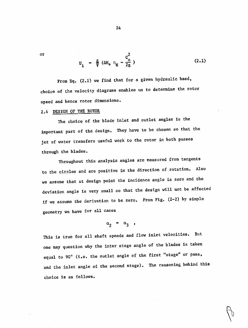
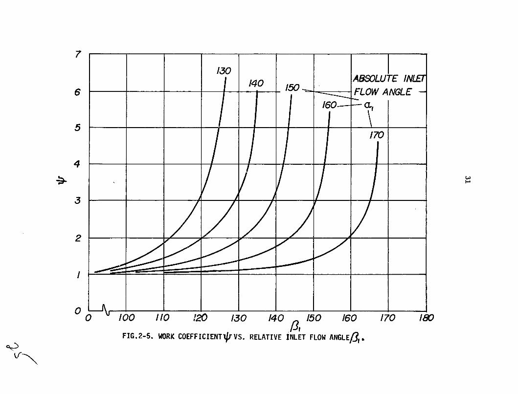
01 are related together by Eq. (2.4).Notice that (, , x and
Now design curves can be drawn using Eqs. (2.4) and (2.10) which may
help to choose the right value of the parameters. Two useful curves
may be,values of x vs. R1 for different values of nozzle angle
and values of x vs. aI for different values of m .
Figure 2-5 shows the design curves based on Eq. (2.4).
Solving Eq. (2.10) for the value of X we get
1 2
= m cosa [ -I 1 ] - + 1 (2.11)x ( mcos tan m Cos
the value of x can be found, orFor any value of m and 81
vice versa.
2.5 LOSSES AND EFFICIENCIES
In cross-flow machines, blades are normally made of curved
bent strips of thin sheet metal. So small variations in inlet flow
angle could cause high incidence losses. Summarily the other losses
can be listed as: hydraulic losses due to skin friction and change
of flow direction in the nozzle and blade passages; losses due to
converging flow in open space inside the rotor; and mechanical
losses.
a) Nozzle losses
For nozzle a factor cv which acts as a velocity correction
factor can be used to define the losses due to skin friction and
converging flow, so

33
C C =
J~Ao
or
c = Cv /2gAH °
For the loss due to the curved nozzle passage the curve given in
Appendix I, will be used, provided a hydraulic diameter is
defined as
Dh 4 x flow area (2.12)h wetted perimeter
If the radius of curvature is R then the curve in Appendix I
provides the values of loss factor k versus deflection angle
for different values of R/Dh , where
2 WI
H K 1-Loss 2g
and W1 is the mean water velocity through the nozzle. Obviously
the mean values of R and Dh should be used to get a better
result.
b) Blade losses
I) Hydraulic-friction losses. The coefficient of friction
for the flow through blade passages can be found based on hydraulic
diameter, and using the curve given in Appendix I. So

34
W2 f oss h Dh 2g
subscript h stands for values evaluated on basis of hydraulic
"L" is the length of the blade passage and W is thediameter.
relative flow velocity.
II) Losses due to flow direction change° In this case we
the curve given in Appendix I, , for the nozzle.can use
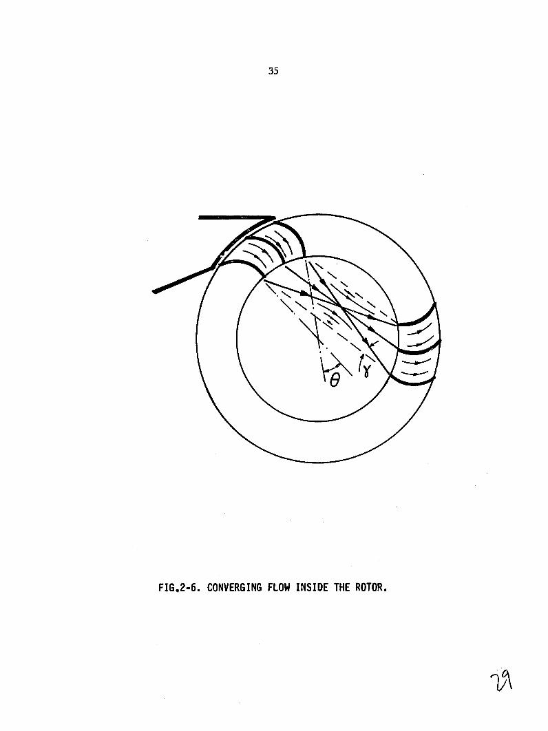
c) Losses within the rotor
As seen in Fig. 2-6, the direction of actual velocity leaving
This effect will cause adifferent blades converges to one point.
change in flow direction entering the second set of blades.
As seen in Fig. 2-6 from simple geometry, the maximum
"y" caused by this effect is half of the admissionincidence angle
the central stream line remainsangle "0". It i; asumed that
angle the closerundeflected. Al'so the bigger the admiss ion is,
;ide jets will get to the inner -;urface of the rotorthe right-hand
on the second p)eis . Thereforeand that will cause negatiV work
the angle of adml!;sion ha!; to be kept a,; nmall as po,5ssible. A
reasonable range of magn iItude for admisslo-n angle is between 200 to
angle the loss due to this effect40'. For thesje Vllue; of admission
is very 3mdll.
d) Efficiencie',
Normally the overall efficiency for a water turbine is
defined ai;
35
FIG,2-6. CONVERGING FLOW INSIDE THE ROTOR.

36
h n nX Q
where Tlh is the hydraulic efficiency of the turbine, and covers
(See also Appendixall the hydraulic losses across the blading.
AH - Hloss Th AH
where AH stands for difference between hydraulic head of the
turbine inlet and outlet.
1The term Im or mechanical efficiency covers all the losses
due to disk friction and bearings and so on and is defined as;
T - loss
m T
where T represents the shaft torque.
Finally qQ is the volumetric efficiency which covers tha
leakages and the flow which passes the turbine without giving any
power
Q - Qgk nQ - Q
where Q is the volume flow rate.
The important part of the evaluation of the efficiency of
a turbine is to find the hydraulic efficiency. This term is very
37
sensitive to the blade profile and flow angles (see Appendix III).
In order to get the hydraulic efficiency of the crossflow turbine
using Eq. (2.15), one has to write all the losses mentioned in the
last section in terms of hydraulic head.
2.6 BLADE DESIGN
As mentioned bef-re the rotor in a crossflow turbine con
sists of two end plates to which the blades are joined. Many
designs do not have a through shaft, so that the torque is trans
mitted to the output shaft by the blades, i.e. the blades experience
all the bending moment due to torque transmission, all the blades
come under a relatively high periodic stress, as at each moment
only a few blades carry the whole flow. Therefore one would like
to avoid long rotor blades and blades with small radial chord.
Stiffer plates may be used to support the blades between
the two end plates and so allow longer rotors. Therefore for a
given power level and hence a specified volume flow rate, if the
rotor can be reinforced with stiffer plates one can go for
smaller rotor diameter and longer rotors and hence higher shaft
speed. The cost for these apparent advantages is that of the
higher complexity.
For the type of design we have chosen, we will only be
Also the bladeconcerned with rotors having no stiffer plates.
profiles will be segments of a circle. Therefore the blades can
be cut out of thin-wall tubes, or made of strips of thin sheet

38
Zz number of blades
die inner dia.
de. outer dia.
L t length of rotor
FIG.2-7. CROSS-FLOW TURBINE-BLADE TERMINOLOGY.

39
metal rolled around a pipe. The most important parameter to be
specified is the ratio of inner to outer diameter of the rotor
"m" which affects most of the other rotor parameters, such as
length, number of blades, etc., effect of m on other blade
design parameters can be found using Eqs. (2.13a) to (2.13f)
which relate these parameters. (See Fig. 2-7 for blade
notation.)
0 C
y- = 0 (2.13a)
2y - BB- (2.13b)
dsin y - sin (2.13c)
2
nc/2) (2.13d)2 sin(8 2
d - d c cos y + d o sin €/2 0
0 2 (2.13e)
o dsin 7/Z (2-13f)
The solidity a is defined as the ratio of the blade chord
to the spacing of the blades on the inner-diameter side of the rotor.
It will be easier to work with the nondimensional forms of
Eqs. (2.13a) to (2.13f). Let's define
12

40
dand
0 o
then,
y - e /2 (2.14a)
2y-€ B - T- (2.14b)
(2.14c)2X sin y = sin
X (2.14d)2 sin y
(2.14e)x cosy + sint/2 = (1-m)
(2.14f)( = mm sin /
As discussed in the last section the hydraulic loss through
the blade passage is a function of the ratio of the radius of
curvature of the blade camberline (centerline) over the hydraulic
diameter of the passage and the deflection angle of the blade.
Figure 2-8 shows the variation of the ratio of the rotor length and
the blade curvature ratios over the rotor outer diameter versus
These curves showvalues of rotor inner-to-outer diameter ratio.
that shorter and more curved blades result from using bigger
values of m.

41
As mentioned in Section 2.5 the loss through the blade
passage is a function of the ratio R/Dh and ec , where Dh is
the passage hydraulic diameter and 0c is the blade deflection
angle. Bigger values of R/Dh and smaller values of 0c give
us less loss. Both these parameters can be found in terms of
geometrical parameters introduced in Eqs. (2.13) and (2.14), as
follows:
4 x flowDhas defined h wetted perimeter
but as pointed out before, flow through the blade passage is the
deflection of a jet of water along pressure side of the blade and
so the jet thickness is fairly constant. Consequently the hydraulic
diameter of the blade passage can be determined by the inner
diameter side of the rotor. By the aid of Fig. 2-7 we then have
4 x (Lxs) Dh = L + 2s
The reason for defining the wetted perimeter as (L +2s)
is that the flow does not fill the passage fully. Only the blade's
pressure side and side walls guide the flow. If W1 is the
a is the rotorrelative velocity of water through the passage and
admission angle then at the inner-diameter side of the rotor we
have:
Q = WA = WIL Tr d
1 1 360 i

--
42
but as madi/d ,then
QL =
Wm do
= (Eq. (2.14) therefore,Defining a c/s and ) = c/d
d Xd
ad_1 =S = 0
Dh we have:Substituting these into the relation for
x d--9-4Q d
-- m W d a
360 + d1loDDh =i2d Q - -+ 0
d o m W7r 360 1 o
Dividing both the denominator and the numerator by do
and naming
c' S
d2 W'360 o 1
then we have
4 E--d m 0
Dh = +C' C+2
m al

43
Also from Eqs. (2.14) we have the definition of
_R
0
or
R 0d0
Therefore
C' 2? - (m a-R M
Dh 4- -m
or
R_ ffi (C'a + 2Xm) Dh 4C'X
The parameter c' will be a constant value for homologous
units of this kind (turbines having similarity in geometry and
velocity diagrams). Figure 2-9 shows the variation of 0 versus
m and the variation of R/Dh versus m for different values of
solidity. From Fig. 2-9 we find that the maximum value of R/Dh
happens at values of m closer to unity as solidity increases.
With reference to Fig. I-1 (Appendix I) we find that the loss
factor for the range of deflection angle we have (between 410 to
580) does not change much with variations of 0c but is strongly
a function of R/Dh , especially for lower values of R/Dh (values
from 1 to about 5). Consequently for a chosen value of solidity a,
the maximum value of R/Dh seems to lead to the efficient passage.

44
.8 1I° ANGLE OF DMISSO
.8NOZZANGLE
.4
.2
0 0 .5 .6 .7 .8 .9 I.
RAND ROTOR LENGTH LFIG.2-8. RATIO OF BLADE RADIUS OFTURVATURE9
OVER ROTOR OUTER DIAMETER VS. ROTOR INNER-TO-OUTER DIA. RATIO m
s8o8
606
---- 205 - 40 Ct
202 UNE 0F- ANGLE OFADMISSION
30"MAXIMUM R NOZZLE ANGLE
30' 0 o .5 s6 .7 .8 .9
m , AND DEFLECTION
FIG.2-9. RATIO OF RADIUS TO HYDRAULIC DIAMETER
ANGLE OF THE BLADE PASSAGE e VS. ROTOR INNER-TO-OUTER DIA. RATIO M.

120 ROTOR ANGLE OF
30 _ADMISSION
so. 00n60
N ACCEPTABLE9
RGO40
20 ____
< LINE OF MINIMUM LOSS O0 _ _ _ _ I
0 .5 .6 _ _
.7 .8 .9 1.0 m
FIG.2-1O. NUMBER OF BLADESZ VS. INNER-TO-OUTER DIA. RATIO M.

46
The design of the rotors with no stiffer plates is more dominated by
mechanical design of the blades than by optimization to get the mini
mum loss. Using Eqs.(2.14a) to (2-14f), the curves shown in Fig.
2-10 can be drawn.
These curves show the number of blades for each choice of
solidity and rotor inner to outer diameter ratio. As the number
of blades is reduced the rotor becomes longer because the throat
width is lessened (Fig. 2-8). Therefore although the blade chord
increases as the number of blades decreases the blades become
more flexible in bending. On the basis of stress aAd stiffness
conclusion, assuming typical material properties and thickness
(e.g. 2mm steel plate for the blades), we have let 18 as the
minimum number of blades.
When the number of blades is increased, the rotor can be
shorter, but the manufacturing difficulties for small workshops
become progressively more severe. We have chosen 60 as the
maximum desirable number of blades. Points inside the closed curve
drawn in Fig. 2-10, give better designs as far as losses and structural
stiffness are concerned.
2.7 SIZING OF A CROSS FLOW TURBINE
For a machine of this type working under constant head, the
velocity of jet of water leaving the nozzle is fixed (Section 2.4).
Therefore the choice of inlet absolute flow angle from the nozzle
affects the size of the rotor, a small nozzle angle being desirable.

47
As discussed in Section 2.5, the angle of admission should also
be kept small in order to reduce the losses within the rotor and
losses due to flow entering the blades in the second pass. The
The inletangle of admission is taken equal to 30 in our machine.
absolute flow angle in a prototype designed by Banki was 160. In
that design the flow crosses the rotor on an approximately horizontal
(i.e. the water entrance and draining points are on a horizontallino
line). He used a cast casing incorporating the nozzle for his
turbine.
As we have tried to avoid complex structures and manufacturing
processes, our design does not have a cast casing like Banki's
Rather we used a steel angle framework with sheetdesign had.
metal covers; there will be a main cover around the rotor which
The nozzle will be a separate part fixedconfines the water spray.
to the frame giving a nozzle angle of 300. That value resulted
in the least complexity of the structural design. (See nozzle rotor
So with reference to Sectioncombination drawing in Section 2.8.)
Draining will2.4 the absolute inlet flow angle "a1" will be 150.
be vertically downward.
From the fact that the work coefficient is equal to 2.0 we
have
Co1 - 2U1.
Assuming a total-to-total efficiency of 75% for the turbine
(nozzle and rotor), from Eq. (2.1) we get,

48
- 69.20 2 /s 2
A(UC& m
then
- 5.88 m/sU1
C1 - 13.88 m/s
Wi 9.00 M/s
The choice of shaft speed depends on how i1trge the rotor
limitations theouter diameter can be and what are the speed for
As we were to use woodea bearings the sliding velocitybearings.
between shaft and bearing bore limite' is to a shaft speed of
300 rpm. This ';peed .; lower than de,-irable, because a high
gear up ratio Is needed to reach the Shaft speed to 1800 rpm
des;ln s1tudie; it would be justifiable(generator speed). In future
high apeeds.to specify bearin gs to run at
Therefore specifying N - 300 rpm we get
d - 0.3743 m
We would like to join the blades- to the side plates by rivets
(see general arrangt, iiu.ni drawing and nozzle-rotor combination
thedrawing In Section 2.8) The re.for,, we would like to have least
bl. ! ;h'In (irdl to0 :m; Ifficlent "'pace forl ,. tponilble ntirid ,r it
tihe bldet Hi Idte plate!;. Usingto theriveting the, bent endri (f
get m - 0.6 and 24 blades.Fig. 2-10 in the laiit nection we

49
(2-13f) we get the followingNow using Eqs. (2-13a) to
First from the velocity diagramresults and blade parameters.
(zero incidence) we get
B = 1300 53'
and then
eC = 520 581
y = 260 29'
R = 0.0956 m
S = 0.0293 m
= C 0.0843 m
wL have previously chosen,
Z = 24
m = 0.6
The inner diameter of the rotor then will be
di = 0.2246 m .
If 20% extra power is specified to cover the mechanical
losses and the losses in the generator then the output shaft
The volume flow rate required will be
power has to be 6 Kw.
Q W 0.0867 m3/s
e lA(u ce)
The length of the rotor then will be

50
L Q 0.164 m -j 7 di W1
a being the admission angle.
Once more recalling the velocity triangles shown in Fig. 2-4,
we can write the following relation
A(u c6) = A(u Ce) + A(u c0) total 1st pass 2nd pass
or
A(U C0 ) = (UICeI U2 C82 ) + (U3 Ce3 - U4C e)
but as we specified,
U2 = U3 U1 = U4 , 6C2 = C83 = 2
2U2 C =0 and A(U C)C 2U 1 1 Ce4 total
Therefore
2 2 2U2 m2U2-_U =A(UC=2U1 0 1 2 1 1(UCpas
2 2
and
= 12U22A(U Caa2nd pass 21

51
The above relations show that for a value of m = 0.6 , the energy
transferred to the rotor in first pass is 82% of the total energy
and only 18% of the total energy is received by the second pass.
This means that as hydraulic losses within the rotor and the
entrance losses in the second pass do not affect the performance of
the turbine very much.
2.8 MECHANICAL DESIGN
The manufacturing processes under which the turbine is to be
made have been the most dominant parameters in the mechanical
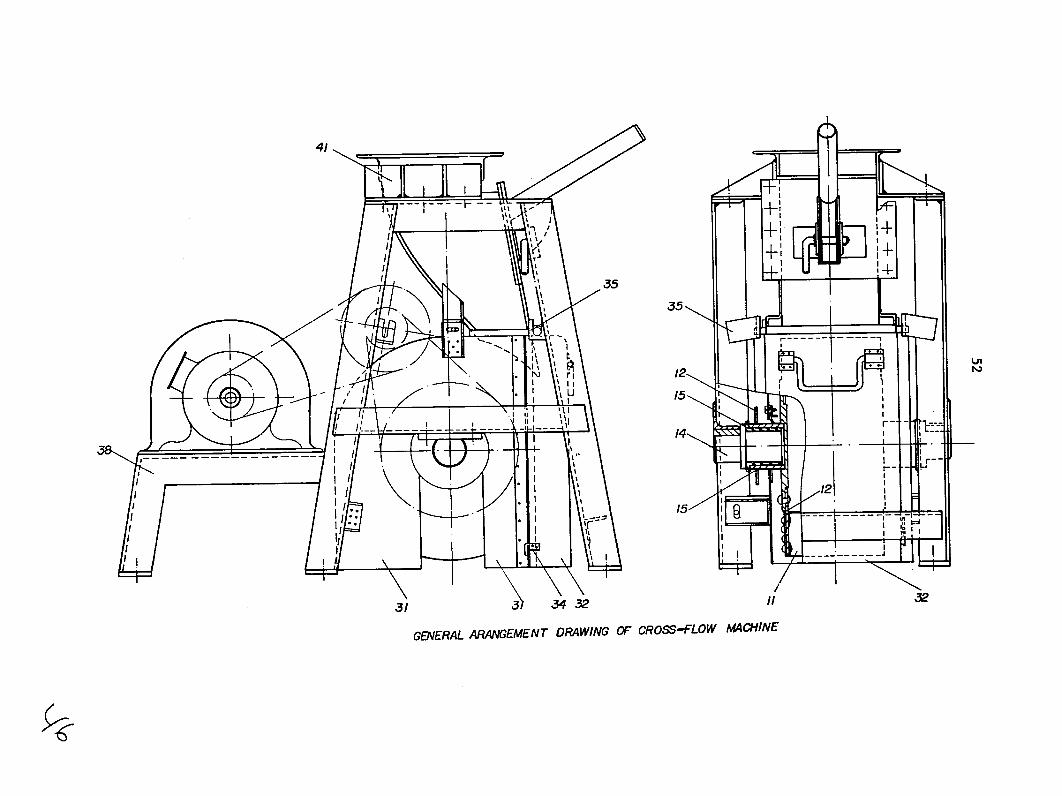
design. The general arrangement drawing, scheme of the nozzle
rotor combination and an isometric view of the machine are submitted
in the following pages. Different parts of the machine are briefly
described as follows:
Rotor
The turbine has a squirrel-cage-shaped rotor, 380 mm O.D.
and 165 mm long. The optimum speed under the design head of 10 m
is 300 rev/min.
It has 24 blades, each blade being simply a circular segment.
Blades can be rolled out of 2 mm galvanized steel sheet (see Part 11
on the general arrangement drawing). They are joined to the rotor
side plates with rivets (Part 12).
The rotor has no drive shaft. Power is transmitted through
the bearing housing which rotates with the rotor, and the shaft
which goes through the rotor bearing supports only the rotor
(Part 14).
41 "
155
15
GEERAl ARANGEMENT ORWING OF CROSS-.FLOW ACHINE

53
NOZZLE-ROTOR COMBINATION OF CROSS-FLOW TURBINE

54
ISOMETRIC VIEW OF CROSS-FLOW MACHINE

55
Bearings
The bearing housing, which is a short piece of circular
steel pipe, is welded to a circular plaj which is fixed to the
rotor side plates with rivets (Part 13).
Bearings are made of a special oil-impregnated wood. Although
there are some limitations for the maximum permissible speed for
this kind of bearing, its low cost and simplicity makes it suitable
for low-speed applications. Furthermore it does not need lubrication.
It works in wet as well as in dry conditions. It requires no seal
(Part 15).
In our design the bearing rotates with the rotor, so equalizing
wear on the wooden bearing and increasing the bearing life.
Chain transmission
Power is transmitted from the rotor to the generator by means
of bicycle chain and gears. A 52-tooth gear is fixed to the circular
plate which is welded to the bearing housing (Part 21).
The generator has a constant speed of 1800 rev/mn. A chain
and gear combination is used which gives a speed ratio of about six
from turbine to generator.
A complete hub and set of five chain cogs for a bicycle
derailleur gear is used for the second speed step up (Part 22).
The unnecessary gears in the gear set are replaced by spacers
and only an 18-tooth gear (being driven by a 52-tooth gear on the
rotor) and a circular plate with a central bore, the same as one of
the gears, is fixed to the gear set. The latter circular plate is

56
be fixed with a 36-tooth gear being used for the second speed-up
step (Part 23). The last gear has 17-teeth and must be fixed to
the generator shaft. For the power level we have in this machine
a good lubrication condition should be provided for the chain.
The two-step transmission in this turbine makes it difficult
to incorporate an oil bath around the chain. As you will see in
Chapter 4 this machine would not be selected as the final choice,
so we did not do further improvements on its transmission system.
In order to increase the life of the chain and sprockets, we recommend
that two chains in parallel be used. Therefore two sprockets should
be installed side by side on each shaft.
Housing
The housing is completely made of thin galvanized sheet steel.
It has a fixed section which covers most of the rotor (Part 31), and
a removable door (Part 32), placed in the back of the turbine, for
servicing. It has a lifting handle and is fastened to the fixed
section with two simple latches (Parts 34 and 35).
Frame
The frame is totally made of angles, welded together. The
generator mounting is a steel plate welded to short legs and its
size may vary when using different generators (Part 38).
Nozzle
The nozzle is completely made of steel plates, welded together
(Part 41). The flow can be changed and set on different valves for
different output powers. This is possible by chaning the angle of

57
flap (Part 42). The semi-circular channel (Part 43) which is welded
to the flap has holes for different settings.
Warning: never change the flow while the turbine is
in operation %_
As the system works under a relatively high head, a change
of flow while the turbine is working can cause "water-hammer" in
the piping which can result in serious damage.
To avoid this there has to be a gate valve before the nozzle.
The flow must be slowly reduced almost to the shut-off position
before changing the flap position. After setting, the valve must
be opened gently.
The possibility of installing a surge-tank as a shock
absorber has not been studied, because it would increase the size
and tha cost of the turbine.
2.9 EVALUATION OF EFFICIENCIES
Knowing the size of different parts of the turbine the
hydraulic efficiency of the turbine can be found. Following the
method given in the last sections we get:
= 76%7h
This efficiency is the total-to-total efficiency and is very close
to our prediction, so the design is acceptable. Taking the effect
of the energy loss by drain flow into account we get,
60%nt-s =

58
If a mechanical efficiency of 94% and a generator efficiency
of 90% is assumed then
at-sm - 56.5%
and.
7tisu M 51%
(See Appendix II.)
2.10 RADIAL-INFLOW PARTIAL-ADMISSION WATER TURBINE
Description
This type of turbine is a potential alternative to the cross
flow and axial types.
The turbine simply consists of a spiral-shaped distributor
with rectangular cross section which distributes the flow in two
opposite portions of its inner circumference, each one being an arc
of 80. The rotor blades are rolled out of sheet metal and are
fastened at one end onlylaround the circumference of the turbine
The flow enters the rotor with a swirlingdisk as cantilevers.
radially inward motion, passes through the blades while still in
the radial plane, and subsequently is deflected to leave the rotor
in the axial direction.
Flow Control
This type as described gives the possibility of controlling
the volume flow to the rotor under constant head. Therefore the
velocity diagrams would keep their design-point geometry and
consequently the turbine would work at its design-point efficiency
through the whole range of power.
SI,

59
ROTATABLE SLEEVE ROTOR BODY
ROTOR BLADES SPIRAL
NOZZLE BLADES
FIG.2-11. RADIAL-INFLOW PARTIAL-ADMISSION WATER TURBINE.

60
The control of the flow could be easily achieved by reducing
the angle of admission. This could be done by installing a rotatable
sleeve between rotor and distributor. The sleeve would have ports
which could be brought more or less into alignment with ports on a
fixed sleeve to vary the admission area.
Dimensions
For specified head (10 m) and power output (5.5 kw) a turbine
of this type would have a diameter of about 220 mm when turning at
450 rpm. However, with this size of the rotor there would be drain
ing problems on the inner side of the rotor.
Unfortunately, increasing the rotor diameter brings out
another problem which is the spiral geometry and size (see Fig.
2). To solve the draining problem by increasing the diameter to
340 mm would reduce the axial width of the rotor to 55 mm and the
speed to 300 rev/min.
This would require a spiral distributor of the same width
(55 mm). To keep the fluid velocity in the spiral small, the radial
dimension of the spiral would have to be increased.
Conclusions
A rectangular cross section of the order of 60 x 200 mm would
result (in entry port). For the range of specific speed in which
we are working, dimensions as large as this make the radial inflow
turbine unattractive. We have not taken the design further.

Chapter 3
DESIGN OF AXIAL-FLOW TURBINES
3.1 DESCRIPTION
In this chapter the task is to design some simple axial
flow turbines as a solution to the problem. We have chosen to
design machines with high hub-to-tip-diameter ratio which enables
us to use untwisted blades for the blading.
Principally, water flows through a set of nozzle blades
(installed all around the circumference of the hub disk), into the
rotor blades, then passes the rotor blades and through the diffuser
to the tailwater. The turbine can be designed as an impulse or a
reaction machine.
3.2 ADVANTAGES
These designs should have comparable advantages with the Banki
type. The design of these machines provides easy manufacturing
processes if they are to be mass produced (i.e. sand casting and
plastic molding).
The blades are made of molded, extruded or cast plastic
which will give accurate profiles and consequently a better design
and off-design performance. Moreover the shaft speed in these
machines is higher than that of the Banki type and therefore a
simpler transmission and a lower gear-up ratio will be needed. These
machines can also be used as a drive motor to drive other machines
besidep the generator.

IOZZLE BLADE
0~.
ROTOR BLADE
U2
FIG.3-1. INLET AND OUTLET VELOCITY DIAGRAMS OFAXIAL-FLOW TURBINE STAGE.
63
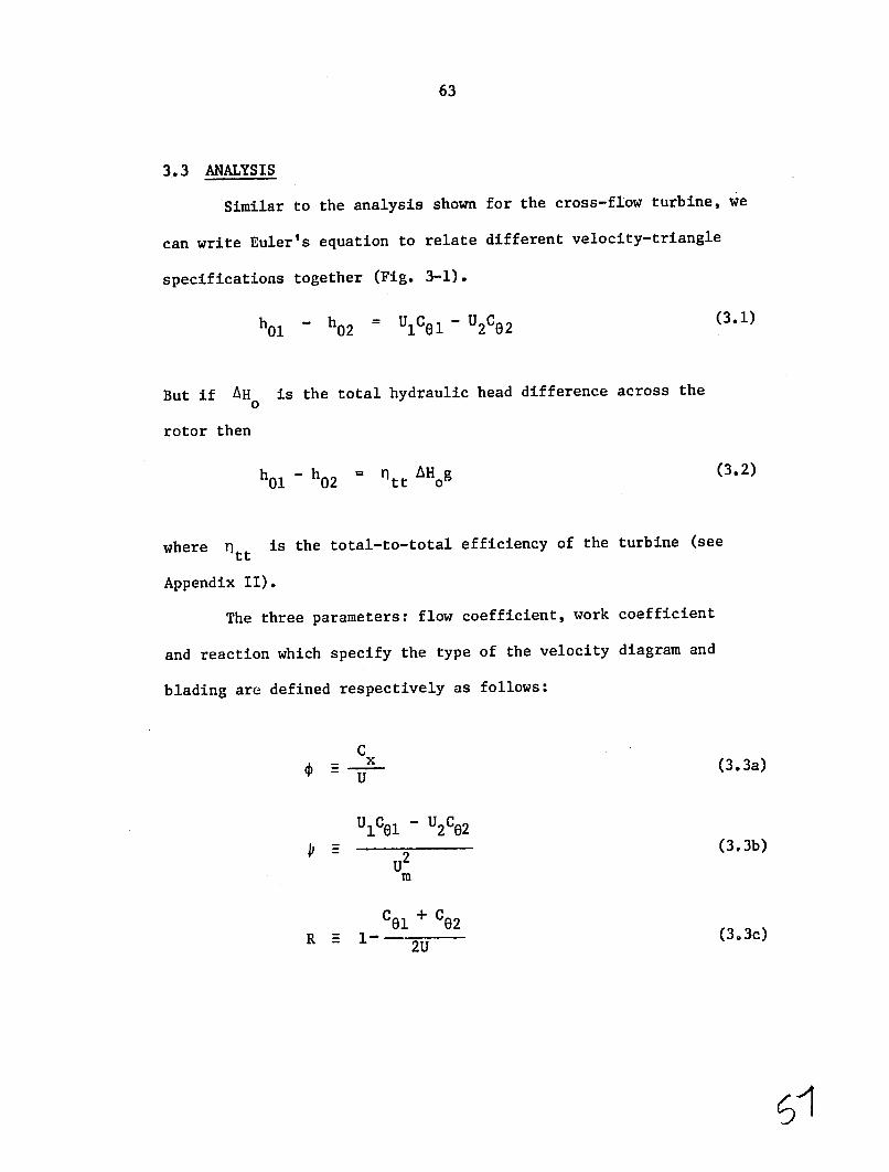
3.3 ANALYSIS
Similar to the analysis shown for the cross-flow turbine, we
can write Euler's equation to relate different velocity-triangle
specifications together (Fig. 3-1).
(3.1)ho - = U1C81 - U2C62h02
But if AH is the total hydraulic head difference across the0
rotor then
= t t AHog (3.2)h0 1 - h 0 2
where ntt is the total-to-total efficiency of the turbine (see
Appendix II).
The three parameters: flow coefficient, work coefficient
and reaction which specify the type of the velocity diagram and
blading are defined respectively as follows:
C (3.3a)UX
UIC1 - U2C02
(3.3b)2 m
C1 + C32R E 1- 2U (3.3c)

64
The analysis is done for the mean diameteryfor the usual
case where C remains constant from inlet to the nozzles to x
Now for each design a velocity triangle canoutlet of the rotor.
R can be specified.be chosen, hence values of 4, c and
A good approach to the design of different machines of this
type with different degrees of reaction is to keep the inlet flow
constant and to vary the two other parametersangle to the rotor "a1"
(i.e. R and 4).
From (3.2) and (3.3b) we have
ntt g AHo034
Now, choice of shaft speed gives us the mean diameter
7T (RPM) (3.5a)60 U
and
(3.5b)d = dt + dh m 2
and mass flow rate will be
(3.6)In WCO
is the output power of the turbine.where W

65
The annulus area then will be
Aa = f--C (3.7)
where p is the density. Also we know that in terms of hub and tip
diameters the annulus area will be
dr2 2 Aa - (d' - dh ) (3.8)
As mentioned before we try to keep the ratio of hub to tip diameter
high enough, to be able to use untwisted blades. A reasonable
value for this ratio is around 0.8.
Now, a choice of velocity triangle gives us the value of
A(U Ce) and hence from Eq. (3.4), (3.6) and (3.7) the values of
UA a are found. Then the shaft speed can be determined and using
Eq. (3.5a) gives us the value of mean diameter. Then using Eqs.
(3.5b) and (3.8) we can find dh and dt .
If the ratio of dh/dt is not acceptable a new shaft speed
has to be chosen to optimize the dh/dt ratio.
3.4 DESIGN OF BLADES
Figure 3-2 shows the terminology used in this design
procedure. To find blade angles from flow angles we may use the
information and curves given in Reference (2). The following two
relations approximate the curves given in Ref. (2) with a good

66
BLADE WIDTH b
FFLOW OUTLET ANGANGL
BLADE BLAELOTLE
ANGLE /3,
STAGER AGLE DEVIATION ANGLE6
-\TRAILING EDGE
FIG.3-2. BLADE TERM INOLOGY.

67
accuracy, for incidence and deviation angles.
A 0ind 700 = 0.25( - 1)(2.6 - a) (3.9)
and 260-A
0.08 +
" = (c/S (3.10)c /
Please see Fig. 3-2 for information on parameters used in above
formulae. These two formulae are useful in preliminary design.
In Eq. (3.10), 6C
or blade turning angle is equal to
0C= I + Aeind + a2 +
so the blade angles will be
= l + AOin dBI
=B2 02 +
Suggested values for leading and trailing edge radii are
re = (0.03 to 0.05)C
rt = (0.02 to 0.01)C

68
The design procedure for the blades is to choose a stagger
angle "A" and an optimum value for solidity a . The optimum
solidity can be estmated by the Zweiffel criterion for the value of
width-to-chord ratio;
b =2.5 cos2a(.1s c 2 (tgal + tg 2) (3.11)
also from Fig. 3-2,
b = cos (3.12)
c
from Eqs. (3.12) and (3.11) we find a ,
c
In steam and gas turbines the dimensions of the blades and
the number of the blades are normally determined by choosing a
reasonable value for chord as far as vibration and stresses are
concerned. In our case, as blades are short, a good choice for the
number of the blades which gives us a reasonable blade passage seems
to be a good approach.
Then finding the dimensions of the blades we can fina tne
blade shapes by trying different curves for the blade profile.
3.5 SIZING OF THE MACHINES
Single-stage axial-flow turbines are normally named on the

69
basis of their velocity triangles. Two possible and most common
types of velocity triangle are: impulse and 50%-reaction.
The design procedure in each case is to guess a value of
Then the machine willtotal-to-total efficiency for the turbine.
be designed with respect to the estimated efficiency. Finally for
the designed machine the efficiency will be calculated using the
method given in Appendix III. The design can then be optimized.
In order to get 5Kw. electrical power from the generator
the turbine itself will be designed for 10% extra power. So the
specifications of the turbine are 5.5 Kw. output power and 10 m.
hydraulic head.
a) Design of an impulse machine
Assumptions are a total-to-total efficiency of 0.80 and
velocity-diagram specifications of: work coefficient of 20
(implicit in an impulse machine), and flow coefficient of 0.8 (which
gives an acceptable nozzle angle). Also we will specify that the
absolute velocity leaving the rotor is to be in the axial
direction, to minimize leaving losses therefore we have,
2 C2
AH0 = 0 1 -H 0 2 = 0g
from Fig. 3-3 we have,
C C
U
Fig. 3.3. IMPULSE VELOCITY DIAGRAM

70
Substituting the last two relations into Eqr. (3.4) and rearranging
for U we have:
Ti .g Hol U = +2
2
applying numerical values we have (at mean diameter);
U = 5.90 m/S
so
U = 69.75 m2/s2
=A(UC)
Then from Eq. (3.6) the volume-flow rate is
Q = 0.0791 m3/s
Then from the velocity diagram
= 68.20a1
00= a2
and
= 51.340
= 51.340I2

71
and
C1 = 13.26 m/s
W1 = W2 - 7.38 m/s
C2 = 3.54 m/s
The choice of the shaft speed has to be done with regard to the
following considerations: a) the value of hub-to-tip diameter ratio
should be around 0.8; and b) a combination of two standard available
sprockets can be found which gives us 1800 rev/min on the generator
shaft. The minimum number of teeth for a 1/2"-pitch sprocket
spinning at 1800 fev/min is 24 teeth. This value is recommended
by almost all manufacturers. Therefore the value of shaft speed
gotten by specifying the hub-to-tip diameter ratio should lead to
an available number for sprocket teeth.
With regard to the above discussion a shaft speed of 540
rev/min gives 80 teeth for the big sprocket. The dimensions of the
rotor then will be
d = 0.2087 m
M
2 0.0168 mA =
a
(

72
and
dt M 0.2347 m
dh = 0.1827 m
blade height = 0.0260 m
The ratio of hub-to-tip diameter ratio is then 0.78 which is in an
acceptable range.
Nozzle and rotor blades should be designedBlade design.
separately for this machine as they have different flow inlet and
outlet angles.
First for nozzle blades: by looking through curves and
information given in Ref. (2) for different blade profiles, for
cases having the same deflection and inlet angle, an optimum
are suggested. (Wesolidity of l5 and a stagger angle of 450
tried several profiles with other staggers but this value gave the
best-looking profile.)
From Eqs. (3.9) and (3.10) we have:
Aeind f 19.250
5.0906 =
The blade angles are then
B, = 19.250
I72.290B2

73
To choose the number of the blades we have to specify the
spacing. From the above specifications we have
b_b cos 45 = 0.71 c
(See Fig. 3-2).)
In this case a different number of blades were tried. Finally
15 blades seemed to be a good number as it gives a reasonable cross
sectional area for the blades (as we want to use plastic blades, we
prefer to have blades with bigger chordal length and hence more
cross-sectional area).
With the above specification nozzle blade sizes are as
follows:
s = 0.0434 m
C = 0.0651 m
b = 0.0462 m
= 0.0025 mrt
rg = 0.0005 m
In the same way calculations for the rotor blades were
done. The results are tabulated in Table 3-1. Also see Fig. 3-4
for blade sections.

1" z a X° A " 1 BI B; S C b r rt 0
NOZZLE 000 68.2 15 1.5 45 19.25 5.09 19.25 73.29 43.4 65.1 46.2 2.5 0.5 12.4
BLADES
ROTOR 51.3 51.3 16 1.5 30 5.13 6.27 56.34 57.57 40.7 61.6 53.35 2.5 0.5 21.8
BLADES
TABLE 3-1: IMPULSE TURBINE BLADING DIMENSIONS (DIMENSIONS IN MM)

75
NOZZLE BLADES
ROTOR BLADES
FIG.3-4. BLADE SECTIONS OF THE AXIAL-FLOW IMPULSE TURBINE.

76
Evaluation of eff.ciencics. With respect to the method given
in Appendix II and information we got about the blades the value of
each loss parameter can be found.
XX XX N N pb pr pt pt ar
4.2 7.20Nozzles 2.48 0.97 1.13 0.10
0.80 0.10 1.2 20.20Rotor blides 9.04 1.12
TABLE 3-2: BLADES LOSS FACTORS
Substituting the numerical values for the parameters in the
n and assuming 1 mm. radial clearance for the rotor equation for
we have,
nt-t= 80.6%
Lt was 80%; therefore, we are close enoughThe assumed value for
to the optimum design.
Then from Appendix II we can find other efficiencies. We
specify chat diffuser blades after the rotor will reduce the velocity
of the flow down to .75 of its value when it leaves the rotor so,
nt_s M, 75%
if mechanical efficiency is 95% and generator efficiency equal to
90% then the machine and the unit efficiencies will be;

77
nt=sm 71.0%
nt_sU = 64.1%
Mechanical design. It is not necessary to describe all the details
of the mechanical design in this report. Therefore only a short
In the next pagesdescription about different parts will be given.
the general-arrangement drawing and turbine section drawing can be
seen. The machine is to run a 5Kw., 1800 RPM generator by means of
chain and sprocket transmission. Further descriptions are
individually given as follows:
This combination has high-accuracyRotor-nozzle combination.
The rotor (see drawing 1, Part ii)components to be made of plastic.
has 16 blades. The up-stream nozzle blades (Part 12) with 15 blades,
are molded into hubsand the downstream diffuser blades (Part 13)
which act as bearings for the rotor, The nose up-stream of the
nozzle blades (Part 14) guides the flow to the nozzles.
These are all installed in a plastic bush (Part 15). This
bush gives a smooth inner surface to the duct surrounding the rotor,
a feature which will increase the efficiehicy.,
Also this plastic bush allows us to use low-cost materials
(even rustable) for the center-section housing tube (Part 22).
The diffuser blades transmit the rotor-thrust-bearing force
to the center section.

-A24 3321 22 15 31 23
34
L 14 12 1/ 13
SEc. A- A
AXIAL FLOW IAiLLSE M4CHINE CROSS SECTION

!iA
MCHINEGEERAL ARRANGEMENT RAWING OF AXIAL FLOW MPULSE

80
The bushing is fixed to the housing be means of a flange
molded to the upstream end (i.e. nozzle size), which is clamped
between the flanges of Parts 21 and 22. The nozzle blading is
fixed to the bushing by square-cross-section projections in the end
of each blade. Theie match up with slots in the bushing. After
assembly the blades are fastened to the bushing with resin adhesive.
The nose in front of the nozzle blading is also fastened to
the hub of the nozzles by structural adhesive. The diffuser
blading is similarly fastened to a flanged bushing, clamped between
the flanges of Parts 22 and 23.
The rotor bearings are lubricated with water. Water flows
in through the hole in the front of the nose and lubricates the
front bearing. Then some water flows to the back bearing through
small holes in the rotor hub.
Housing and frame. The housing has three individual sections which
are bolted together. The upstream section, Part 21, is actually an
adaptor. It enables us to connect the turbine to a standard 10"
water pipe and flange. The center section (Part 22) encloses the
turbine itself and the downstream section (Part 23) is the outlet
collector.
Different parts of the housing can be made of rolled steel
sheets welded to steel flanges. However, if there are local
facilities for sand casting, Parts 21 and 22 would be better made
from cast iron.

81
The frame (Part 25) is made of steel angles welded together.
The turbine is bolted to the frame using some of the flange bolts
through the housing back plate (Part 24). The upper plate (Part 26)
of the frame supports the generator. These are shown in Figure 2.
Transmission system. Power is transmitted from the rotor to the
output shaft by the means of a coupling disk (Part 31). This disk
has four slots on its circumference which match up with small teeth
in the bore of the rotor stub shaft.
As the disk is loosely in contact with the rotor it can
transmit only torque, and no bending moment or thrust force, to the
output shaft.
The output shaft (Part 32) is supported by a flange bearing
(Part 33) which is fixed to the housing back plate by bolts. The
flange bearing has a rubber seal in the drain side, which prevents
water leaking into the bearing.
The ball bearing in the flange bearing, together with a
tapered bush and a nut with locking washer, keeps the shaft in
the right position.
In order to raise the rotor speed to the generator speed a
combination of two sprockets is used with a tooth ratio of four
(Parts 34 and 35). The chain used in this system is standard 1/2"
chain (bicycle chain). The sprockets have 80 and 24 teeth on the
rotor and generator shafts, respectively.

82
We do not recommend the use of standard bicycle sprockets
in this case. To transmit five kw at a speed of 1800 RPM would be
loading them up to their maximum strength and would leave no safety
margin.
To fix the larger sprocket to the rotor shaft a split taper
This is done to avoid any need forbushing (Part 36) is used.
hammering or pressing on the shaft.
Using the unit in powers lower than five kw
To run the turbine at a power level less than five kw, the
flow to the turbine has to be reduced by the means of a value
Obviouslyinstalled at least a meter before the turbine inlet.
the turbine will work at its best efficiency when it is run fully
loaded.
Different possibilities for controlling the output pouer
by installing some kind of mechanism were studied, but all cases
I feelresult in a significant increase in size and complexity.
that users would not find these possibilities attractive.
b) Design of a reaction machine
This section is concerned with design of a 50% reaction axial
The principles of the calculations are exactly the sameturbine.
as for the impulse machine. Therefore only the assumptions and
tabulated results will be presented. In fact the structure of both
turbines are also the same, so to avoid repeating the mechanical
drawing of this machine it is not submitted as it is quite similar

83
to impulse machine. But a short description of the differences is
given in the following paragraphs.
The significance of the 50% reaction machine is that its
rotor and nozzle blades will have the same cross section. We
specify a work coefficient of oneand absolute flow angle to the
rotor to be the same for both
impulse and reaction turbines.
The absolute flow leaving the oil
rotor will then be in the U
axial direction. The first FIG. 3-5: REACTION VELOCITY DIAGRAM
The result of the guess for the total-to-total efficiency is 85%.
velocity diagram calculation is:
= = 68.201l 82
81= 0.002 =
U = 8.84 m/s
2/s2A(UC8) = 78.08 m or J/Kg
Q = 0.0704 m3/s
IC = W = 9.52 m/s2
2 Cx W = 3.54 m/s
A suitable shaft speed for above results which can give an
accpetable dh/dt is 720 RPM. Therefore;

84
d - 0.2345 m m
= 0.2615dt
dh = 0.2075 m
blade height = 0.027
dh/dt = 0.79
Blade design. For simplicity the rotor-blade section will
be used for both nozzle and rotor blading. But because of differences
between number of the blades for the nozzle and the rotor, the solidity
of bladings will be different. For preliminary design let's select
a stagger of 450, 15 blades for nozzle and 16 blades for the rotor.
From the Zweiffel criterion (Eq. (3.11)) for rotor blades we have
b -- = 0.86s
also
b- cos 0.71 C
Then blade dimensions will be as follows (Table 3-3):
0
b c AMiS B B2 re rt
NOZZLEBLAZE 15 48.76 39.3 55.3 20.0 6.4 94.6 20 74.6 2.5 0.5BLADES
ROTORBLADE 16 45.76 39.3 55.3 20.0 604 94.6 20 74.6 2.5 0.5BLADES
TABLE 3-3: REACTION-TURBINE BLADE DIMENSIONS.

85
NOZZLE BLADES
ROTOR BLADES
FIG.3-6. BLADE SECTIONS OF THE AXIAL-FLOW REACTION TURBINE.

86
The blade cross-sections are shown in Fig. 3-5.
Evaluation of efficiencies. Using the method given in
Appendix III, the values of different loss coefficients are as
given in Table 3-4:
AXpt Xar XXPb Npr Npt
8.751.0 .1
ROTOR 4,48 1.03 0.12 0.1 4.0 9.27
NOZZLES 4.15 LA.l 4.0
LOSS FACTORS OF REACTION-MACHINE BLADINGTABLE 3-4:
mm radial clearance for the rotorSpecifying 1. to l5
blade on the tip then the value of total-to-total efficiency can
be found, which is,
nt-t f 85.6%
For preliminary design this is close enough to the first guess, so
that the design is acceptable.
If we specify that diffuser blades will diffuse the flow to
half of its absolute velocity when leaving the rotor, then the total
to-static efficiency will be,
83.6%nt-s =
If 95% mechanical efficiency and 90% generator efficiency
are assumed as before then the machine and the unit efficiencies are,

87
nt-sm 0 79.4%. , t-su M 71.5%
Mechanical design. The general mechanical design on both
impulse and reaction machines are the same. Therefore no further
details about this reaction machine will be given, other than to
mention the differences in size and performance. The output speed
of this machine is more than that of the impulse turbine, and the
turbine itself is slightly bigger in size, but there is not much
difference in the total sizes of the units (turbine, frame and
generator, altogether).
The diffuser blades and axial diffuser in this machine are
longer and give better diffusion. which results in a few points
increase in efficiency.
The transmission ratio is 2.5 and the same size chalia (1/2")
is used with two sprockets having 24 and 60 teeth on the gelierator
and rotor shafts, respectively.

Chapter 4
DISCUSSION ON ADVANTAGES OF DIFFERENT TYPES
As seen in the last chapters, each of the studied prototypes
had individually some advantages and some dis3dvantages. Looking
at the problem from the view of a developing country, the price of
the turbine, the manufacturing processes under which the turbine is
going to be made and the type of maintenance and service needed are
important parameters in the choice of the best machine.
All machines are designed not to need skilled maintenance.
Therefore cost and manufacturing requirements have to be discussed.
The crossflow turbine gives both possibilities of being manufactured
locally in farming areas and/or being manufactured in industrial
areas and shipped to farms. But axial-flow turbines should be
made centrally and shipped to farms. The type of processes under
which the cross-flow turbine could be made are mostly intermediate
processes such as sheet-metals fabrications, but the axial-flow
turbines have parts which need more sophisticated processes (i.e.
plastic molding, and casting, etc.). To satisfy the goals of the
Technology Adaptation Program it might be preferred to choose
processes which provide improvements in industry in the developing
countries. In that case encouraging industries such as plastic
molders may be of great importance.
The amount of labor which has to be put into making each
cross-flow turbine is much higher than what has to be done for the
CC /

90
axial-flow type. The axial-flow machines would probably be cheaper
because of automation and their smaller size when produced in large
numbers.
Comparison of the structures of the turbines shows that, the
high speed of the reaction machine is an advantage over the impulse
and cross flow machines, as it provides a lower gear up ratio to the
electrical generator, so that a simpler transmission and lower forces
in chain and sprocketi are entailed.
For the kind of generator speed we have chosen the chain
must work in an oil bath and be well lubricated, otherwise it will
not last long even for the axial flow reaction machine. Therefore
the low speed of cross-flow turbine and its two-step transmission
mkes it unattractive, because a far more expensive transmission
becomes necessary.
A big portion of the price of each of the units is the
The rest of the construction cost seems likely togenerator cost.
be similar for all units for small scale production. For large
scale production the cross flow will be much more costly than the
axial types. This is because the material cost for the axial flow
machines is small but initial investments for molds and dyes are
required.
WhileFinally the efficiencies of the machines differ.
there is often surplus water flow aiailable a high efficiency machine
requi.ring a lower water flow will therefore require less costly pipes,
channels, values and so forth.

91
The following table shows the efficiencies of the different
machines.
Cross-Flow Axial-Flow Axial-Flow
Turbine Impulse Turbine Reaction Turbine
t-t 76% 80% 85%
t-s 60% 75% 83.5%
t-sm 56.5% 71% 79.5%
t-su 51% 64% 71.5%
Key:
t-t 2 total-to-total efficiency of turbine blading
t-s 2 total-to-static efficiency of turbine blading
t-sm 2 total-to-static efficiency of machine (shaft power)
t-su H total-to-static efficiency of unit (electrical power)
Based on all considerations we chose the reaction machine as
the best solution to the problem.
4.1 IMPROVEMENTS ON REACTION MACHINE
The preliminary design shown in the last chapter has some
questionable features. Here we try to improve on that design as
much as possible. Following are some items which it seems necessary
to cover.
By looking at the general-arrangement drawing submitted in
this chapter (DRN, No. AF301), the difference between the rotor
nozzle combinations in two schemes can be seen.
92
This improved design provides less hydrostatic force on the
rotor. The atmospheric pressure is bypassed through the rotor
central hole to the other side of the rotor, hence equalizing the
pressure on the two sides of the rotor and reducing the axial force
on the rotor. The sliding surfaces between the rotor and diffuser
hubs are covered with thin stainless-steel sheets which reduce the
(For the high pressure and velocityfriction and give a long life.
the best kinds of plastic can not last and on sliding surfaces ever
they melt.) Lubrication of these surfaces is possible by the aid
of holes in the rotor hub and grooves on the plates. The lubricant
water is supplied from upstream through the holes in the stator hub.
The front adaptor in the improved machine is changed. The
to connect the turbine to 8" diameter piping.new adapter enables us
The smaller tube and valve size reduces the cost.
The oil bath in the back of the turbine provides good
lubricating conditions for the chain and sprockets, and hence
increases the transmission system's life.
The blade profiles are also changed. The new blades have a
settling angle of 380 and their shapes are also optimized for the
best performance.
4.2 Off.-Design Performance
The type of flow control we recommend for the machine is to
The basic use a gate valve installed one m. ahead of the machine.
assumption is that the turbine is going to be run under fairly steady

.9 180 Q= CONSTANT
- 160.8Z
Q .7
120.6
.4 T - .s0
oc •II - 2
.2 - 40
.1 20
•0 0 0 200 400 600 800 1000 1200 1400
SHAFT SPEED R.P.M.
FIG.4-1. CHARACTERISTIC CURVES OF REACTION MACHINE FOR CONSTANT FLOW RATE.

.9
.8 N= 740 R.P.M. 70
05 - E0
1 .
0) 01 4550
30(I
43 20
.2
.1 /0
0. 0
FLOW RATE m3 x lOC
FIG.4-2. CHARACTERISTIC CURVES OF REACTION MACHINE IN CONSTANT SPEED.
2

95
loads. Therefore the required power can be set on the machine and
slight changes in frequency up to 5% would be acceptable.
More sophisticated systems to control the turbine will cause
big increases in size and price of the machine, which makes the
machine unattractive to customers.
Based on this assumption the characteristic curves of the'
These curves are theoreticalturbine are shown in Figures 4-1 and 4-2.
The off-design performance is predicurves and based on predictions.
cated using the method given in Reference (3), which has been found
to have a high degree of accuracy.

APPENDIX I
TABLE OF PARTS AND WORKING DRAWINGS
Following are the complete working drawings of the modified
reaction machine. Each drawing has a reference number. Using these
numbers all information about each part can be found from the table
Special information on material, type of manufacturingprovided.
process under which the part should be made or sub-drawings, are
given under the heading "Remarks."
For the case of complicated parts, drawings for additional
sections or subparts are submitted which are marked by letters "A,"
"B," "C," etc., after the master part's reference number. (AF300
stands for 'axial-flow reaction turbine.")

AF33,' N
F335
F325
00
AF3AI32
AF3272
A A , AF3329
A'F3F 0
AAF316 G R R G TU N33
GENERAL
AAF32
ARRANGEMENT OF MODIF TED REACTION TURBINE.A 3O

TABLE OF PARTS AND
LIST OF DRAWINGS OF REACTION TURBINE COMPONENTS
PART NUMBER NUMBER NAME OF PART REQ' D MATERIAL REMARKS
AF311 FRONT ADAPTOR 1 CAST IRON
AF312 MIDDLE SECTION 1 CAST IRON HOLES OF FLANGES SHOULD BE ALIGNED
AF313 DRAIN CHUTE 1 STEEL SEE SUBDRAWINGS
AF313A EACK PLATE 1 10MM. PLATE
AF313B FRONT FLANGE 1 15M1 PLATE
AF313C CURVED PLATE 1 8MM PLATE
AF313D SIDE PLATE 2 5MM PLATE
AF313E FRONT PLATE 1 5MM PLATE
... continued
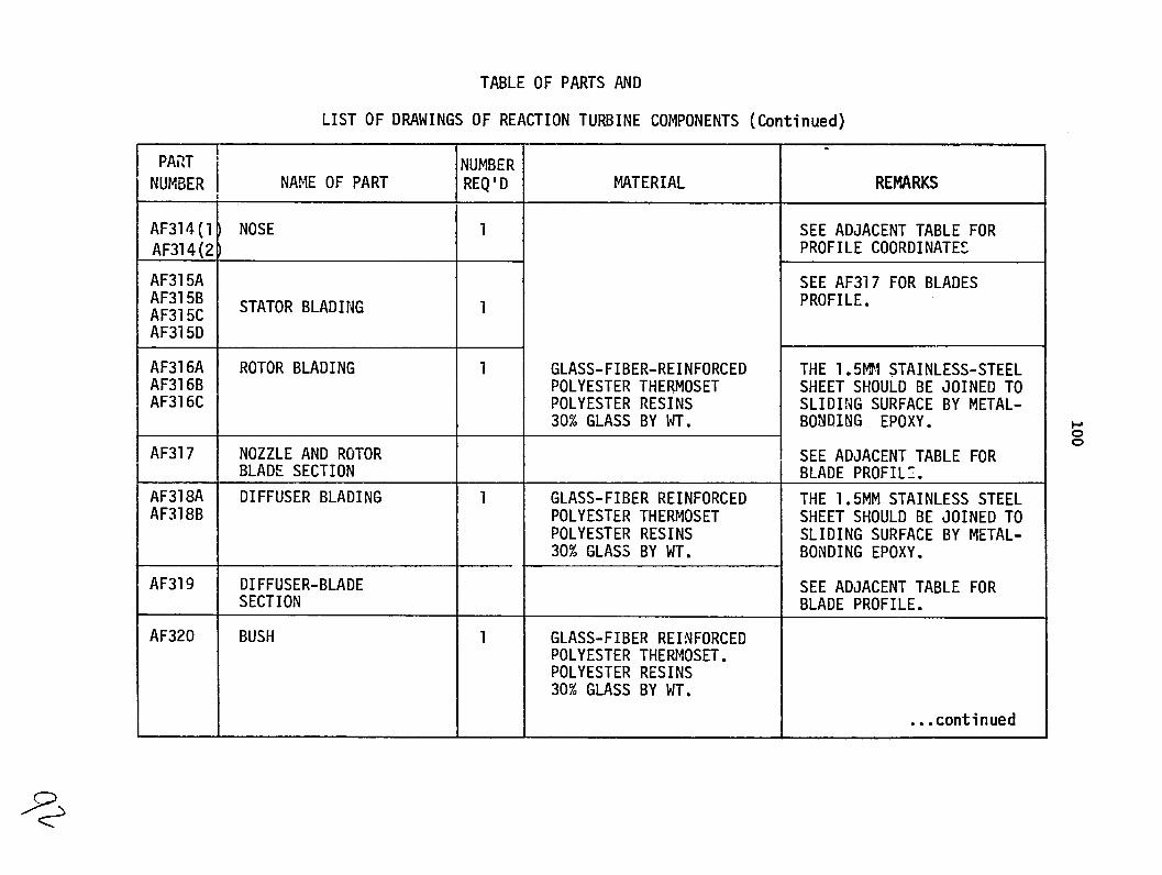
TABLE OF PARTS AND
LIST OF DRAWINGS OF REACTION TURBINE COMPONENTS (Continued)
PART NUMBER NAME OF PART
AF314(l AF314(2
NOSE
AF315A AF315B AF315C AF315D
STATOR BLADING
AF316A AF316B AF316C
ROTOR BLADING
AF317
AF318A AF318B
NOZZLE AND ROTOR BLADE SECTION
DIFFUSER BLADING
AF319 DIFFUSER-BLADE SECTION
AF320 BUSH
NUMBER REQ'D
1
1
1
1
MATERIAL
GLASS-FIBER-REINFORCED POLYESTER THERMOSET POLYESTER RESINS 30% GLASS BY WT.
GLASS-FIBER REINFORCED POLYESTER THERMOSET POLYESTER RESINS 30% GLASS BY WT.
GLASS-FIBER REINFORCED POLYESTER THERMOSET. POLYESTER RESINS 30% GLASS BY WT.
REMARKS
SEE ADJACENT TABLE FOR PROFILE COORDINATES
SEE AF317 FOR BLADES PROFILE.
THE 1.5101 STAINLESS-STEEL SHEET SHOULD BE JOINED TO SLIDING SURFACE BY METAL-BONDING EPOXY.
SEE ADJACENT TABLE FOR BLADE PROFILE.
THE 1.5MM STAINLESS STEEL SHEET SHOULD BE JOINED TO SLIDING SURFACE BY METAL-BONDING EPOXY.
SEE ADJACENT TABLE FOR BLADE PROFILE.
...continued
0

TABLE OF PARTS AND
LIST OF DRAWINGS OF REACTION TURBINE COMPONENTS (Continued)
PART I
NUMBER NAME OF PART
AF321A SLOTTED DISK
AF321B KEY
AF322 SHAFT
HUB ASSEMBLY
AF323A HUB HOUSING
AF323B FRONT CAP
AF323C BALL BEARING
AF323D SEAL
AF323E* (3/16"x32)x5/16" BOLT
NUMBER
REQ'D
I
2
1
1
1
1
1
3
MATERIAL
ALUMINUM
HARD STEEL
STAINLESS STEEL
CAST STEEL
1.5MM STEEL SHEET
M.R.C. BEARING 206-SX ADAPTER AND NUT G-Y
GARLOCK 78x 0542 COMP NO. 26448-05 DES. GRP. D.
REMARKS
EQUIVALENT STANDARD PARTS WITH THE SAME SIZE CAN ALSO BE USED.
ROUND HEAD
__j.. .continued
*no drawing; standard component

TABLE OF PARTS AND
LIST OF DRAWINGS OF REACTION TURBINE COMPONENTS (Continued)
PART NUMBER REMARKSREQ'D MATERIALNUMBER NAME OF PART
NO. OF TEETH 60AF324 BIG SPROCKET 1 BROWIING 40P60 TYPE 4 PITCH 1/2"
PITCH CIRCLE DIA. 9.554"BUSHING Pl FOR TYPE 40 CHAIN
NO. OF TEETH 24AF325 SMALL SPROCKET 1 BROWNING 4024 PITCH 1/2" PITCH DIA. CIRCLE 3.831" FOR TYPE 40 CHAIN
AF326* CHAIN 1 BROWNING NO. 40 1/2" PITCH NO. 40 A.S.R.C.
...continued
*no drawing; standard component
P

TABLE OF PARTS AND
LIST OF DRAWINGS OF REACTION TURBINE COMPONENTS (Continued)
PART
NUMBER I NAME OF PART NUMBERR REQ'D
-MATERIAL REMARKS
AF327 FRAME 1 STEEL
AF327A
AF327B
SIDE ANGLES
TOP ANGLE
2 + 2
2
80x80x8 L
80x80x8 L 2 OFF AS DRAWN
OPPOSITE HAND
AF327C TOP PLATE 1 80MM PLATE
AF327D BAR 2 40x8 FLATBAR
AF327E FOUNDATION PLATE 4 IOMM PLATE
AF328 OIL BATH 1 2 AND 3MM STEEL SHEETS
SEAMWELDED
AF329 OIL-BATH COVER 1 2MM STEEL SHEET
I ...continued

TABLE OF PARTS AND
LIST OF DRAWINGS OF REACTION TURBINE COMPONENTS (Continued)
PART 1'NI NUMBER NAME OF PART
AF330* GENERATOR
AF331A* (5/8"xl2)x2 1/2" BOLT
AF331B*, 5/8"x12 NUT
AF331C * l 5/8" LOCK WASHER
AF332A* (1/2"x12) 1-1/2" BOLT
AF332B* 1/2"x12 NUT
AF332C* 1/2" LOCK WASHER
AF333A* (9/16"xl2)x2" BOLT
AF333B* (9/16"x12)xNUT
AF333C* 9/16" PLAIN WASHER
AF333D*i 9/16" LOCK WASHER
AF334 * ALIGNMENT-PIN
AF335A* (3/8'516) 2" BOLT
AF335B* 3/8" PLAIN WASHER
AF335C* (3/8'!516) WING NUT
I
UMBER REQ' D
I1 I
___1
20
20 20
4
4
4
4
4
4
4
4
1
2
1
MATERIAL
WINCO INC. SERIES 5KS4G-3
HARD STEEL
REMARKS
4 POLE, 5KW, 115/230 VOLTS 21.7 AMP. 60 CYCLE 1800 R.P.M.
PH.
HEXAGON HEADED
HEXAGON HEADED
HEXAGON HEADED
...End
*no drawing; standard component
0
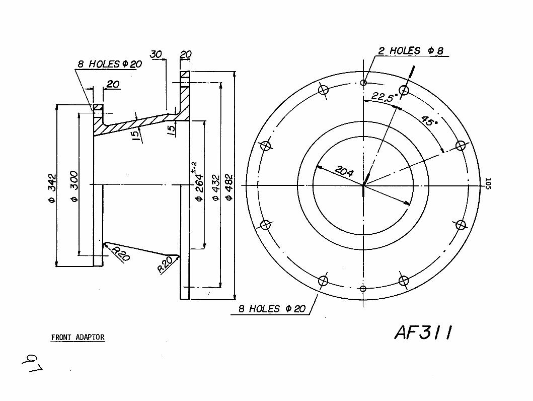
W0 20 2_ HOLES 0 8 8 HOLES 0 20 - r
3002
h')
H8 HOLES 20"
AF31IFRONT ADAPTOR

20; r/02HOE ,.1 r- Tho~
20 20
- 14a
8 HOLES 020
AF312MIDDLE SECTION

_
1 A_ _F313~A B3
A
.0000
AF3i3 E AF313 D
AF313DAIN CliTE

--7
134
_ _ _ _ _ _ 390
AF313 ABACK PLATE

2 HOLES 0 8
4-5.
8 HOLES _31
FRONT FLMoE AF3 13 E

I-I
.t.. 180,
237-
AF313 CCURVED PLATE
-K

175
5
AFJI13 D2SIDE PLATE
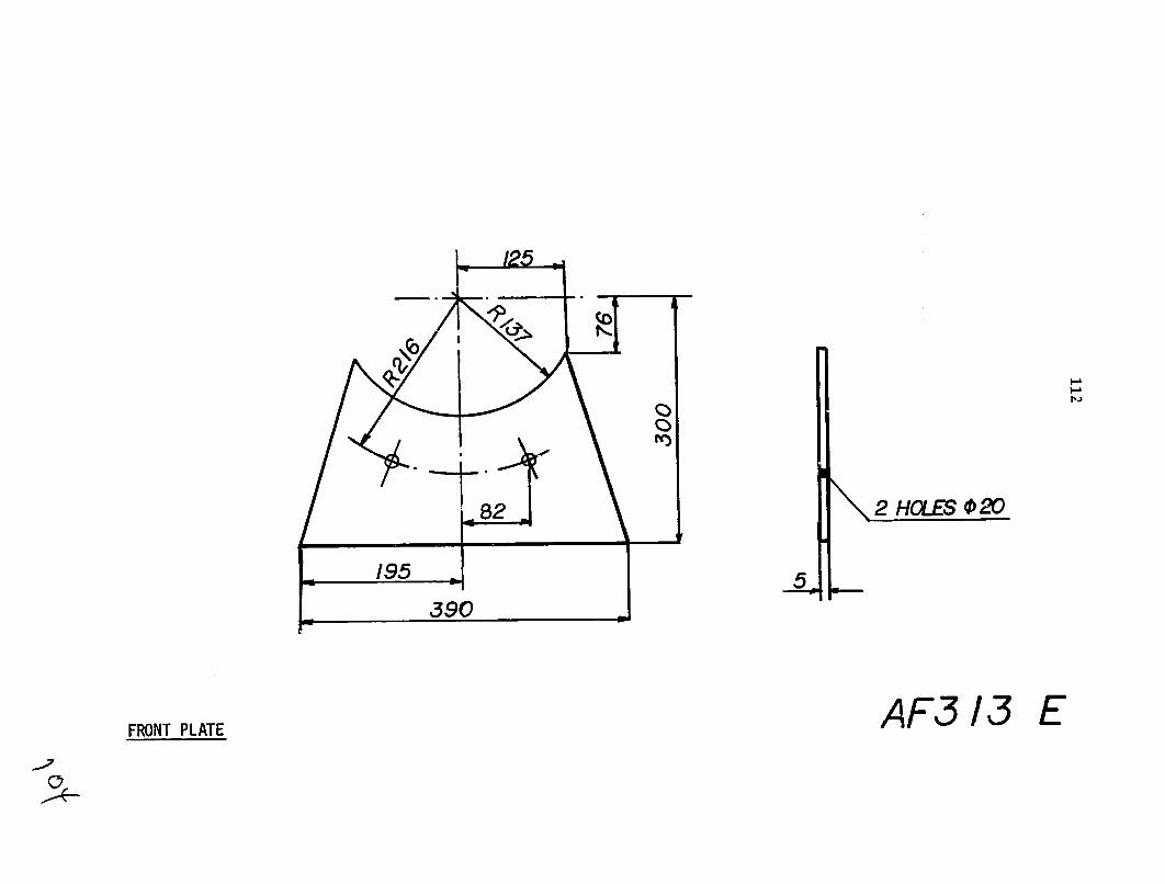
S390
AF3 13 EFRONT PLATE

160
NOSE ( ) A
F314 Q

Joo
oooo
oU0O
UO
U1O
.U'#
0 0
0 0
Qoo
oooo
ooot
~ooo
oeou
lou°
o
NOSE
()
AF31
4

-A
10
-.
/
STATOR ,-,,oo -T
NG
AF5 15 A

AF315 B

B . 7.5 I ByF
3
STATR BAD,.G SEc.A-A /AF3 15 C

0 8
U-)a
SEC. B-B
AF3 15 DSTATOR________

to
,
55 S
ROTOR BLADIN AF316 A

ROTOR BLADING A3 BP16

ROTOR BLADING SEC.A-A AF316 C

CD
) 6
66__
6__
__
__
3_
,66
--a
!a
A
%
I-O
it
-(A
P ra
t~
. !n
h
F,
:-J
FO
8)-
' Z
J
--
-M
= C
-D
0D
m%
z
z IJ
-j
r31%
D M
0 Z
r1
Q0
-00
(71"
D'U
*lz
4I7
3 Z
Z
0Or07
L7
1U,0
Cl
L3C
7 C
nLi
n z
m3
(TI
m.7
(7
1(7
C7%
nM
oMLn
MN
)-4
--P
-P
b4!b
W
W
WW
W
m
mA
) w
m
m
cA)
A
n o
~h j
I
C)
co
co
.I(
L"
-;b
w
a-
-
AF3
17
NOZZ
LE
AND
ROTO
R BL
ADE
SECT
ION

co60
,
0
DIFFUSER BLADING
(1 of 2)
AF318
A

L smcA-A
DIFFUSER BLADING (2 of 2) AF3 18 B

c%
U
Cii
mi
pb
.
b .~
w
~ w
~ w
~
w~
"i
m
ra
(D
OO
w
O00
%
30O
0 m
&
3L"
%m
bw
C
)DC
D--
lO
A
OwC
D
4 41
r,
jc
b P-P
)r
) C
DC
D
a
000
ww
-o
4ww
.
DE
A
oL
C
) 4bc
NP
"4
AF3
19
DIFF
USER
-BLA
DE
SECT
ION
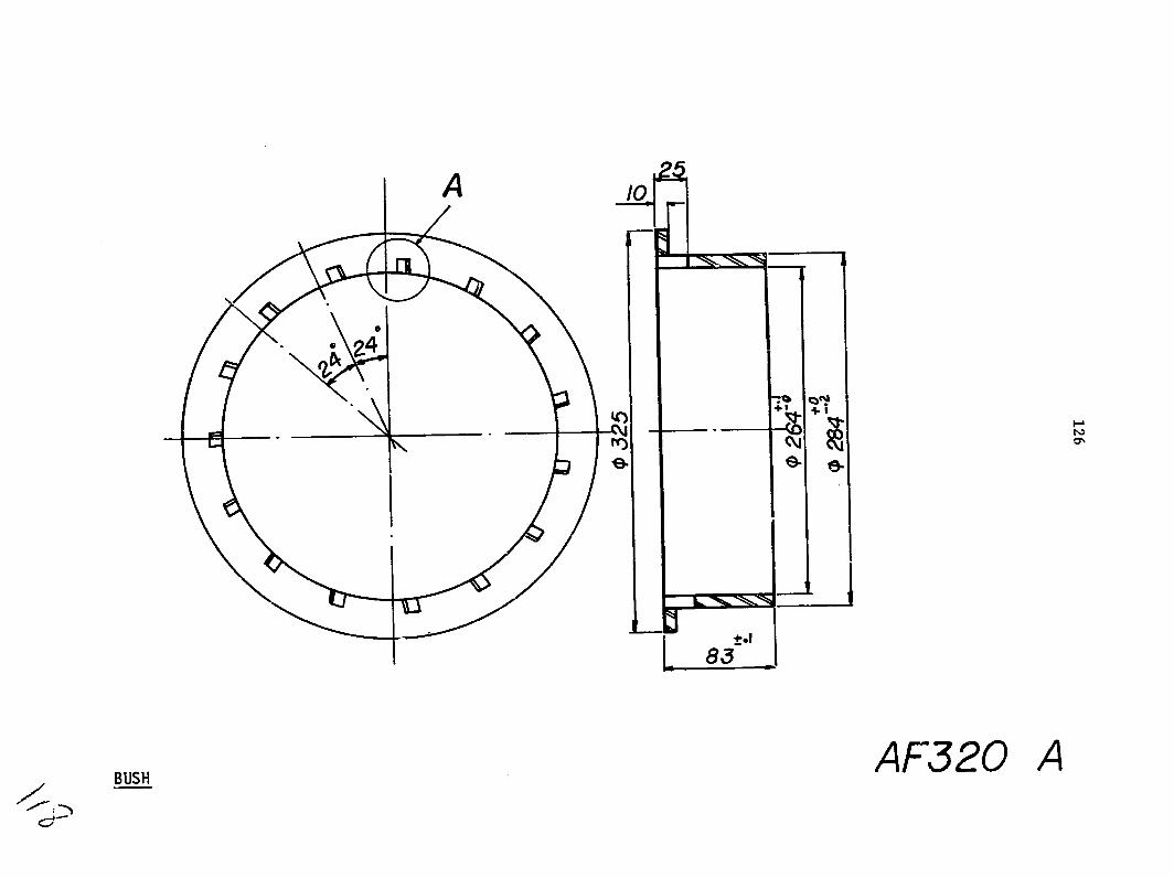
I0
00
L83t.
BUSH AF320 A

A
-~~ DETAIL OF "A"FROM AF320A SC F 2

300
35 L SEc -A-A A SEC. B-B
AF321 ASLOTTED DISK

KEY AF321 B

350
220/0
.33
AF322
sHAFT
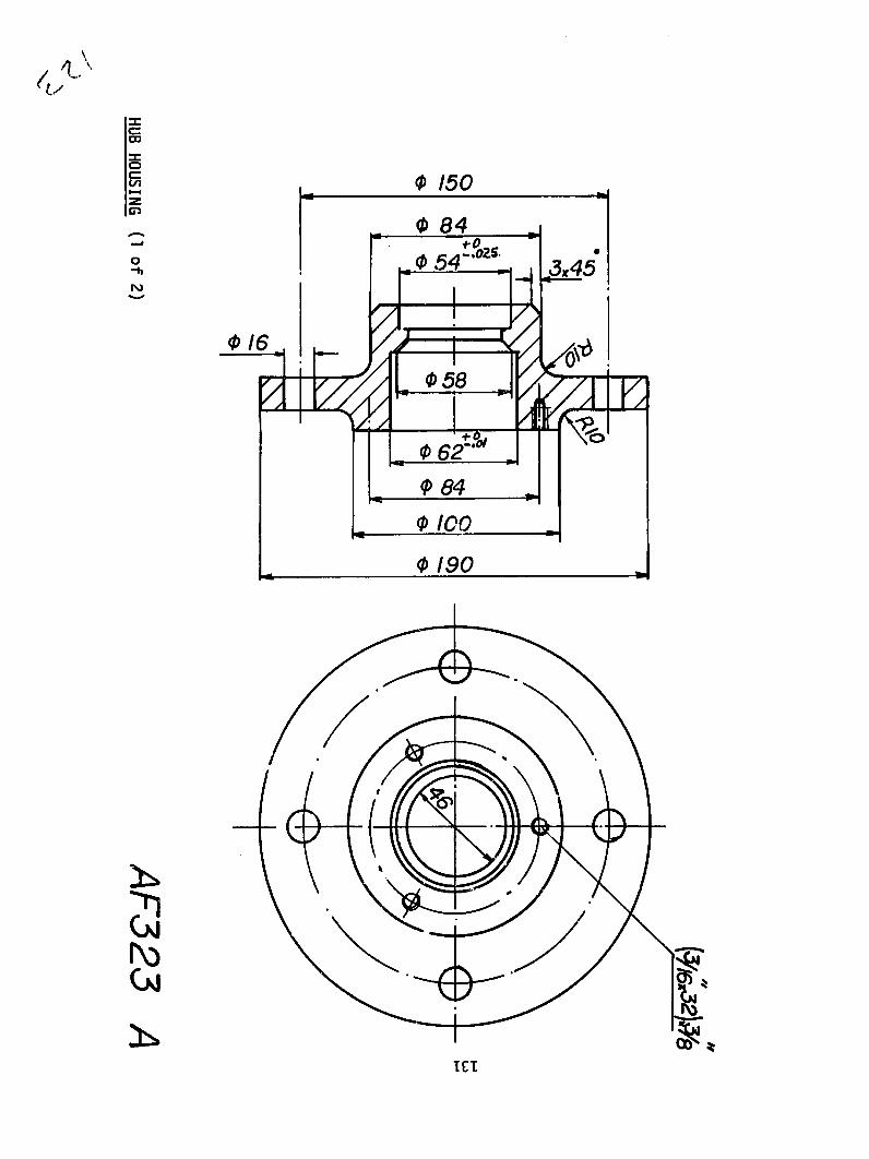
N
HUB HOUSING (1 of
2) A
F323
A
o"Z

38.
[-60
HUB HOUSING DETAIL (2 of 2) AF323 A
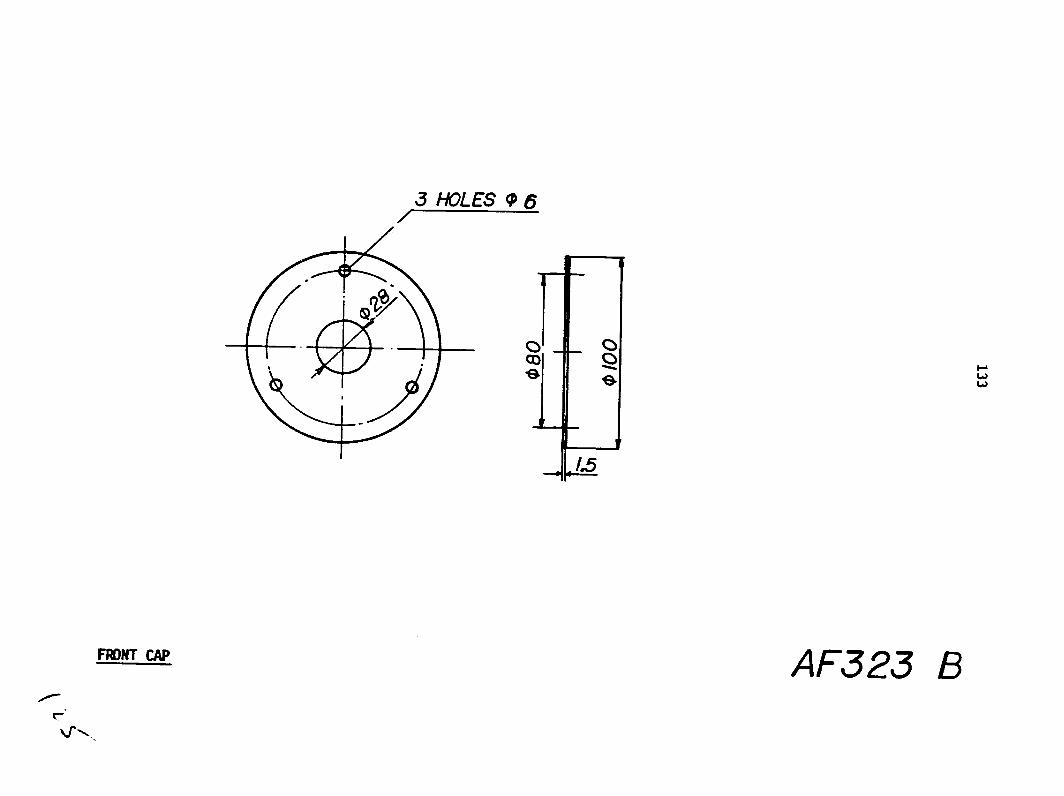
3 HOLES 05
1A5
M~fcm AF323 B

16
5C
BMI BEM____._323

C4C
AF323
DSE&L

.28
4
B2A
F2
BIG SPROCKT AF324l

T.2
84
orcrr
I I S
MA
LLPR
OC
KY
EW
AY
AF
3

165 .313 .
---- 17
/I S
I I '00
20I I I I
34 II
35FRAME -41 (1 of 2) AF327

480
FRAME (plan view) 2 of 2 AF327

--
.80
I--~~~~~O -7---
2Q
574
AF327 ASIDE ANGLES

402
72- 258-8
i~" ,--7
611 2O
TOP E AF327 B
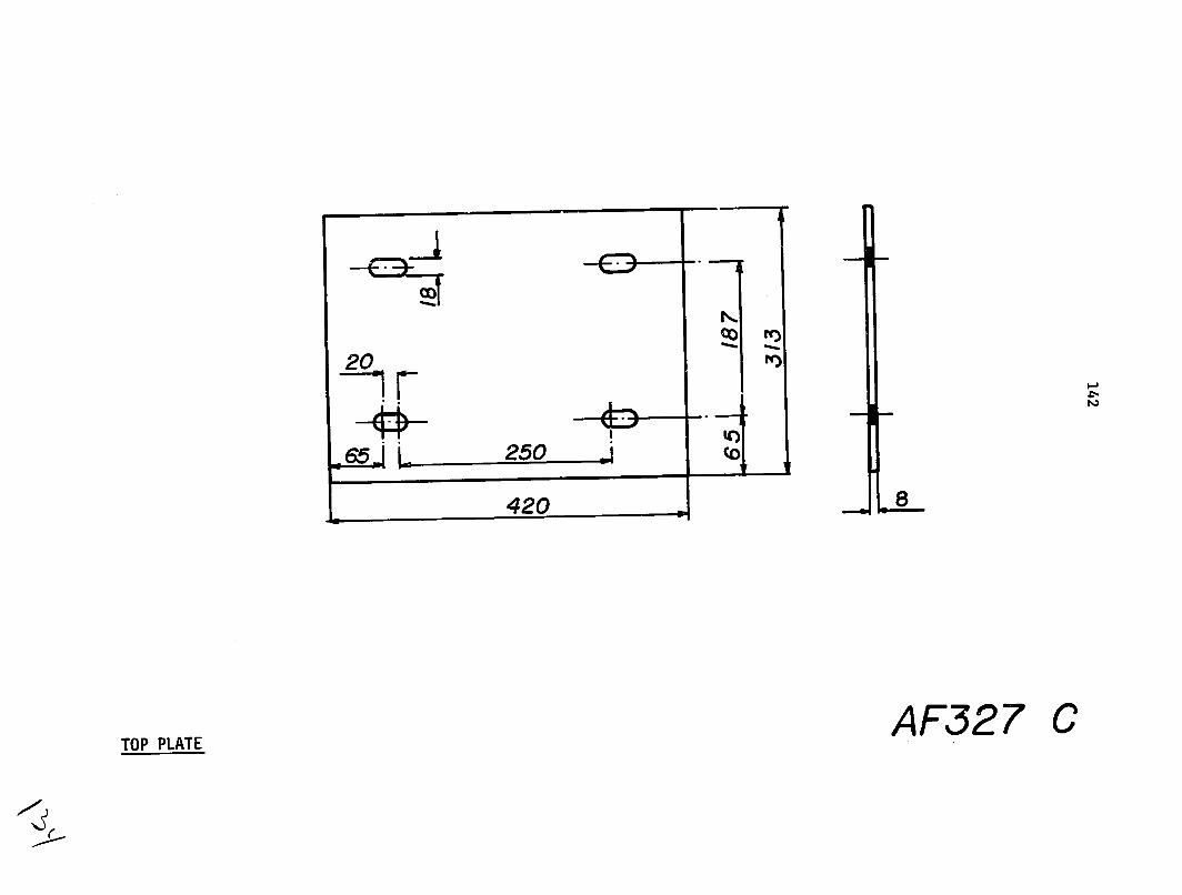
20
L 250 (10
8420
AF327 CTOP PLATE

420 a
II D I-.
80 /0
0E20 E
E BAR AND FOUNDATION PLATE AF32 7 D

030 120
Cj
3
c o _- .
4 HOLES 016
2
OIL BATHA 32

0170
to
265
OIL BATH COVER AF329

35
AF334ALIGNMENT-PIN

APPENDIX II
FRICTION LOSS IN NONCIRCULAR CONDUITS
Pressure drop due to flow through a non-circular cross
section bend can be found from;
2 Ap = K
2
where K is the loss factor, v the average flow velocity and p
is the mass density. K is a factor of hydraulic diameter of the
cross-section and the radius of the bend, as well as the deflection
angle of the bend (Fig. I-1)o
The hydraulic diameter is defined as;
AD E 4 x flow area
h - wetted perimeter
and then pressure drop due to friction loss can also be expressed
in terms of Dh, as:
V2Lf-Ap h Dh 2
where L is the length of the conduit and fh is the friction
factor on the basis of hydraulic diameter. Obviously Re and
e/D should be defined as,
v Dh and c/D 4Re R 4v- Dh
then fh can be found using Fig. 1-2.
147

--
148
0.20
-R.---2.1.5
0 .1
4n
010%10
-'0.05 " / 01 VALUES OF R/Dh(:1"05
0 0 20 40 60 80 100
DEFLECTION ANGLE
FIG. 1. LOSS FACTOR FOR BENDS.(ASCE,J.IYDRAULIC DIV.,NOV. 65)
i~- --. 1- .. Fi e. il111111-
-lIil~ . IiII-it{IIIJT ~ l.,o m 002I K , itionoI- I--Drown Tubing 0000150.02 iliLt1 1'iiil I llllll:C° m°.E s ' 0.000005 FtT,
tiu~n~~U~ z~cmmrcial Steel 001 inor 1 --Ati 0.,0004sphalt Cost Iron 01 Galvanized Iron 00005
, Cast Iron 0.00085 Wood Slave 00006-0003
o 0006e i Hic00 Stez .0l!ii:00, -03o/o -ooo,1,-00000 0. - D H
.001 ,I,W ' ILhK
0.002
lie •VD/L
2.FRICTION FACTOR f VS. Re. FOR DIFFERENT e/D. (W.M.Rohsenew andFIG. H.Y.Chol, Heat,Mass and Momentum Transfer p 58 )

149
APPENDIX III
EFFICIENCIES
The total-to-total efficiency of a turbine is defined as
=1 turbine output power tt -enthalpy drop from inlet total pressure
and temperature to outlet total pressure
This definition of efficiency is concerned with the blading hydraulic
losses.
The total-to-static efficiency of a turbine is
defined as,
Turbine output power
t-s enthalpy drop from inlet total pressure and temperature to outlet static pressure
This efficiency concerns the amount of energy going out of the
turbine by drain flow plus the internal losses of the blading.
For a turbine as a machine an overall total-to-static
efficiency of the machine can be defined which should include the
disk friction and other mechanical losses. That is
at-sm _ t-s x nm
where nm is the mechanical efficiency of the machine and defined
as,
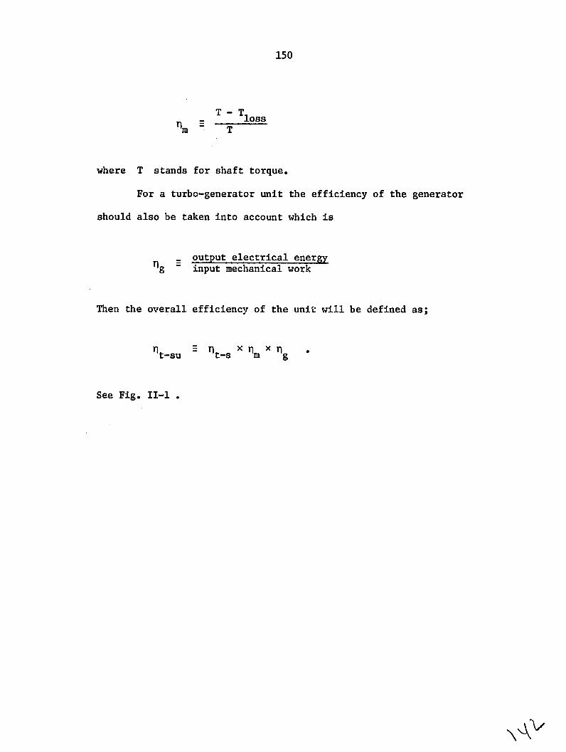
150
T Tloss m- T
where T stands for shaft torque.
For a turbo-generator unit the efficiency of the generator
should also be taken into account which is
_ output electrical energy g -input mechanical work
Then the overall efficiency of the unit will be defined as;
ft-su = nt_s 1 nm x 7g
See Fig. II-i

151
TOTAL HYDRAULIC ENERGY INTO TURBI
ENERGY LEAVING THE TURBINE TO TA IL-WATER
HYDRAULIC LOSSES
MECHANICAL LOSSES
GENERATOR LOSSES
OUTPUT ELECTRICAL POWER
(GENERATOR)
FIG. 1 -,SCHEME OF LOSSES INWATER TURBO-GENERATORS.

APPENDIX IV
PERFORMANCE ESTIMATION OF AXIAL-FLOW TURBINES
There are several ways to evaluate the efficiency of an
axial-flow turbine. The method given here which seems very
straightforward is based on the method given in the paper written
by H.R.M. Craig and H.J.A. Cox and published in the Institution
of Mechanical Engineering, Volume 185 32/71, 1970-71.
THE METHOD
For an axial-flow turbine stage, losses can be divided into
two groups. Group I losses are due to profile and secondary losses
of the nozzle and rotor blading, and group 2 losses are due to disk
friction, leakages, etc. Here we will be concerned only with group
1 losses. Therefore blading efficiency can be defined as
work done in blading
t-tb work done in blading + group 1 losses
It is convenient to evaluate the group 1 losses as loss
factors based on relative blade outlet velocities. Therefore,
022 = X -+Group 1 losses
W2
where Xn and X r are the sum of loss factors due to profile and
secondary losses etc. for the nozzle and rotor, respectively.
153

154
Then to take the losses due to tip leakage and etc. into
account we have to multiply the value of blading efficiency by
the area ratio defined as follows;
Rotor blade swept areaA r annulus area
.Evaluationof loss factors
The blade loss factor is the sum of profile loss factor
Xp and secondary loss factor Xs , where the former one is
defined as
K K N N N +(AXp) +(A) + (AX) m
Xp pb Npi pr pt p (AXp)s/e pm
Each one of these are defined as:
Xpb basic profile loss
N 2 loss correction factor due to incidence
N 2 loss correction factor due to high Reynolds Number pr
N t loss correction factor due to trailing edgept
(AXp)t profile loss factor increment due to trailing edge
(AX ) s profile loss factor increment due to back surface -radiusp s/e
(AXp)M profile loss factor increment due to high Mach number

155
This method can acceptably be used for axial-flow water
In this turbines of the kind that
this report is concerned with.
and, (AXp)s/e case for design-point preliminary
design (AXp)m
Xp will be piwould be zero and the
simple form for
+ (AXp)tXp =XpbNpr Np
Each of these parameters can be found using curves given
in
Figs. 111-2 to 111-6. The Reynolds Number is defined on the
blade opening as;
C 1W20 2 Re = ---- or
Fee Fig. 111-1 for the terminology of the blades.
The secondary-loss factor can be found using Figures
111-7
X is defined as and 111-8, where the secondary-loss
factor
Xs (Ns)h/bX(Xs)b
where
basic secondary-loss factor (Xs)b
(Ns)h/b secondary-loss ratio.

156
Guidit-Incidebi
* ~w ~ - A --
RXC /Back surface Arc lenqt used l0ad r definer o'rfrccton
ratio Backbone lengt.h .5
Fig. 1. Turbine blade and velocity triangle notation
14 at m npim lss
CIw speed - cone,',on
Mr 2 0 30 - 40 50 60 70 't
F'10U E NL
Ilwsed¢Ne~~n
. itpaaeer ,\,N~
0 i 2 . Lf r 60\7rmeer9F

157
4
30-
Z6
z
05 06 07 0.3-1 01 OZ 03 04 RATIO'- I
Fig.J. Contraction ratio for average profiles
40 _ ! ccU. L .,, IN8 Use lca speed valueLm
" ,n;asp-rcneterxis/b)s!,lfi !,- o 004 008 OIZ.q 35 o! otet C,ge far a .n2 a - Fluid outlet
0 20angle B
O z I 5, ,1 -
2/Lontra tion ratio
U'A - _kn4
'1-100,
1- 1
15 . . . .a..'
-J]
006 008 010012 20 30 40 5C 60 70 80 90 1O0 110 '20 002O04
telsTRAILiNG -7.E THCKNESS TOPITCH RATIO-MODIFIED LIFT COEFFC.NT-Flx (s,b':
Fig. 5 .Trailing edge thickness lossesFig.4. Basic profile loss
7)~

158
-100
_ _ _ - 0-- (kslb)xl 3
(ks-eqi ivalent sandI r irlns;ze
2
200
REYNO0Set,NMBERbase on fadeishn)
205 '
|04. 5104 10 SxlO 10
I~~0 fi-nish)h____
300
05 I 0 5
Fig.~~ ~ ~ ~ ~RYO'D NUBEroti factor Renar-bas-epdc RATIO COSag18,--Z, ,? .e e0~y~t€ e.ct
-/ 4 Fig.G.~g ProillosrtoaansSenlsnmecor m yeffectclos
-aco
Z -J__ 6
-A
, o4/
o 0~00 0.1005 2 s / 4i^s
Fi.7 eodr os-se4 0t 3K.AY44
rtofco0RTOARS
0-SQUAR
010 OF
L~!~
6 517E44E0 _.voctjotezA
Fig.9.Scondry lss-bsic oss acto

159
LIST OF SYMBOLS
A area
B blade angle
b width of the blades
C flow velocity, absolute
c chord of the blade
d diameter
f friction factor
g acceleration due to gravity
H hydraulic head
h blade height
h enthalpy
i incidence angle
K head-loss factor
L length
Imass flow rate
N rotational speed
0 opening of the blades
P pressure
Q volume flow rate
r radius
s spacing of the blades
T torque
.. continued
6
160
-LIST OF SYMBOLS (continued)
U blade tangential velocity
W rr-lative velocity, flow
Z number of blades
a angle of absolute velocity
angle of relative velocity
A deop or rise of a vaiable
deviation angle
T1 efficiency
o turning angle
A stagger or setting angle
p mass density
a solidity
* flow coefficient
'work coefficient
w speed of revolution (angular velocity)

161
SUBSCRIPTS
a annulus
h hub
i inlet
I leading edge
m mean value
n nozzle
o outlet
p profile
r rotor and radial direction
t tip
x axial direction
0 stagnation property
1 inlet to the blade
2 out of blade
B tangential direction

163
REFERENCES
(1) Horlock, J.H. Axial Flow Turbines. Robert E. Kreiger Publishing Co., Huntington, New York, 1973.
(2) Dunavent, J. C.,and Erwin, J. R. Investigation of Related Series of Turbine Blade Profiles in Cascade. National Advisory Committee for Aeronautics, Washington, NACA. TN3802.
(3) Craig, H. R. M., and Cox, H. J. A. Performance Estimation of Axial Flow Turbines. The Institution of Mechanical Engineers (Thermodynamics and Fluid Mechanics Group), Volume 185 32/71, 1970-71.