Embed Size (px)
Citation preview
Essex Electronics, Inc. | 805.684.7601 | 800.KEY-LESS | fax 805.684.0232 | keyless.com
InstallatIon & InstructIon Manual
SKE Series12-Pad
Essex Electronics, Inc. | 805.684.7601 | 800.KEY-LESS | fax 805.684.0232 | keyless.comi
All rights reserved. No part of this documentation may be repro-duced in any form, without prior written consent of Essex Electron-ics, Inc. Essex Electronics shall not be liable for errors contained in this manual. The information in this document is subject to change without notice. Essex Electronics, Inc. reserves the right to modify this documentation and to make improvements or changes to the product(s) contained in this documentation at any time.
Document Information IOMK1 Installation/Operations Manual for the SKE Series 12-Pad 3x4 and 2x6 - April 2016. This documentation is also applicable to prior revisions except where noted.
trademarks Keyless Entry® is a registered trademark of Essex Electronics, Inc.
Certifications The SKE-34 is listed by CSA for Elevator Equipment. CSA B44.1-04/ASME-A17.5-2004. Class 2411 02.
contact Information Essex Electronics, Incorporated 1130 Mark Avenue, Carpinteria, CA 93013 (805) 684-7601 or (800) 539-5377 (KEY-LESS) FAX (805) 684-0232
Website: keyless.com General email: [email protected] Technical Support email: [email protected]
Copyright© 2011 Essex Electronics, Inc. All rights reserved.
sKE series 12-Pad self-contained Keyless Entry® system With relay
Essex Electronics, Inc. | 805.684.7601 | 800.KEY-LESS | fax 805.684.0232 | keyless.com ii
Introduction ....................................................................................1 Overview - The SKE Series .............................................................1 Keypad ............................................................................................1 Keypad Specifications .....................................................................1 Keypad Part Numbers .....................................................................2Keypad connector Diagram .........................................................3Keypad Configuration ...................................................................5self-contained Keyless Entry® system With relay...................7 Specifications ..................................................................................7 Configuration ...................................................................................7Programming overview ................................................................9Programming system setup ......................................................10normal system operation ..........................................................15 Keypad LED Status Indicators.......................................................15 Tamper Alarm ................................................................................15Programming Individual users ..................................................16Warranty & repairs .....................................................................24
table of contents

Essex Electronics, Inc. | 805.684.7601 | 800.KEY-LESS | fax 805.684.0232 | keyless.comiii
1Essex Electronics, Inc. | 805.684.7601 | 800.KEY-LESS | fax 805.684.0232 | keyless.com
Introduction Overview – The SKE Series 12-Pad
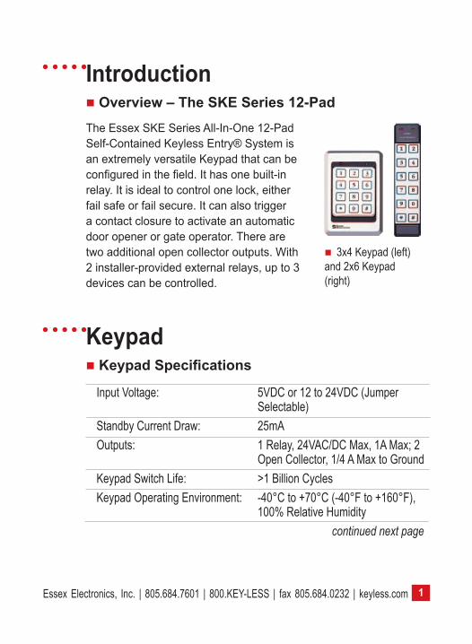
3x4 Keypad (left) and 2x6 Keypad (right)
The Essex SKE Series All-In-One 12-Pad Self-Contained Keyless Entry® System is an extremely versatile Keypad that can be configured in the field. It has one built-in relay. It is ideal to control one lock, either fail safe or fail secure. It can also trigger a contact closure to activate an automatic door opener or gate operator. There are two additional open collector outputs. With 2 installer-provided external relays, up to 3 devices can be controlled.
Input Voltage: 5VDC or 12 to 24VDC (Jumper Selectable)
Standby Current Draw: 25mAOutputs: 1 Relay, 24VAC/DC Max, 1A Max; 2
Open Collector, 1/4 A Max to GroundKeypad Switch Life: >1 Billion CyclesKeypad Operating Environment: -40°C to +70°C (-40°F to +160°F),
100% Relative Humidity continued next page
Keypad Keypad Specifications
Essex Electronics, Inc. | 805.684.7601 | 800.KEY-LESS | fax 805.684.0232 | keyless.com2
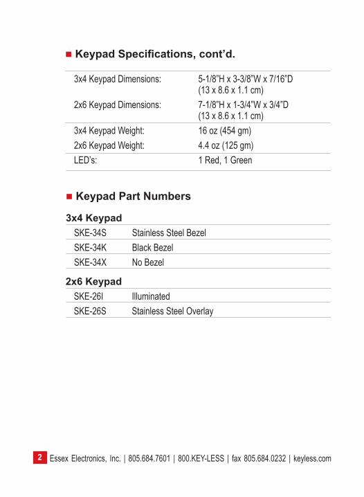
2x6 KeypadSKE-26I IlluminatedSKE-26S Stainless Steel Overlay
Keypad Part Numbers
3x4 KeypadSKE-34S Stainless Steel BezelSKE-34K Black BezelSKE-34X No Bezel
3x4 Keypad Dimensions: 5-1/8”H x 3-3/8”W x 7/16”D (13 x 8.6 x 1.1 cm)
2x6 Keypad Dimensions: 7-1/8”H x 1-3/4”W x 3/4”D (13 x 8.6 x 1.1 cm)
3x4 Keypad Weight: 16 oz (454 gm) 2x6 Keypad Weight: 4.4 oz (125 gm)LED’s: 1 Red, 1 Green
Keypad Specifications, cont’d.
3Essex Electronics, Inc. | 805.684.7601 | 800.KEY-LESS | fax 805.684.0232 | keyless.com
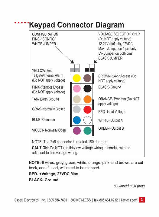
Keypad Connector Diagram
NOTE: 6 wires, grey, green, white, orange, pink, and brown, are cut back, and if used, will need to be stripped.RED- +Voltage, 27VDC MaxBLACK- Ground continued next page
CONFIGURATION PINS- “CONFIG” WHITE JUMPER
VOLTAGE SELECT DC ONLY (Do NOT apply voltage)12-24V (default), 27VDC Max - Jumper on 1 pin only5V- Jumper on both pinsBLACK JUMPER
YELLOW- Anti Tailgate/Internal Alarm (Do NOT apply voltage)
PINK- Remote Bypass (Do NOT apply voltage)
BLUE- Common
BROWN- 24-hr Access (Do NOT apply voltage)
TAN- Earth Ground
BLACK- Ground
ORANGE- Program (Do NOT apply voltage)
VIOLET- Normally Open
RED- Input Voltage
WHITE- Output A
GREEN- Output B
NOTE: The 2x6 connector is rotated 180 degrees.CAUTION: Do NOT run this low voltage wiring in conduit with or adjacent to line voltage wiring.
GRAY- Normally Closed
Essex Electronics, Inc. | 805.684.7601 | 800.KEY-LESS | fax 805.684.0232 | keyless.com4
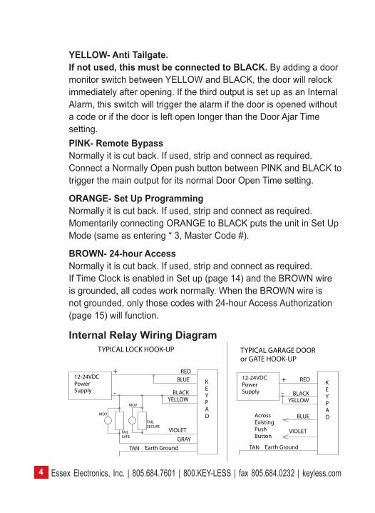
YELLOW- Anti Tailgate. If not used, this must be connected to BLACK. By adding a door monitor switch between YELLOW and BLACK, the door will relock immediately after opening. If the third output is set up as an Internal Alarm, this switch will trigger the alarm if the door is opened without a code or if the door is left open longer than the Door Ajar Time setting. PINK- Remote BypassNormally it is cut back. If used, strip and connect as required. Connect a Normally Open push button between PINK and BLACK to trigger the main output for its normal Door Open Time setting.
ORANGE- Set Up ProgrammingNormally it is cut back. If used, strip and connect as required. Momentarily connecting ORANGE to BLACK puts the unit in Set Up Mode (same as entering * 3, Master Code #).
BROWN- 24-hour AccessNormally it is cut back. If used, strip and connect as required. If Time Clock is enabled in Set up (page 14) and the BROWN wire is grounded, all codes work normally. When the BROWN wire is not grounded, only those codes with 24-hour Access Authorization (page 15) will function.
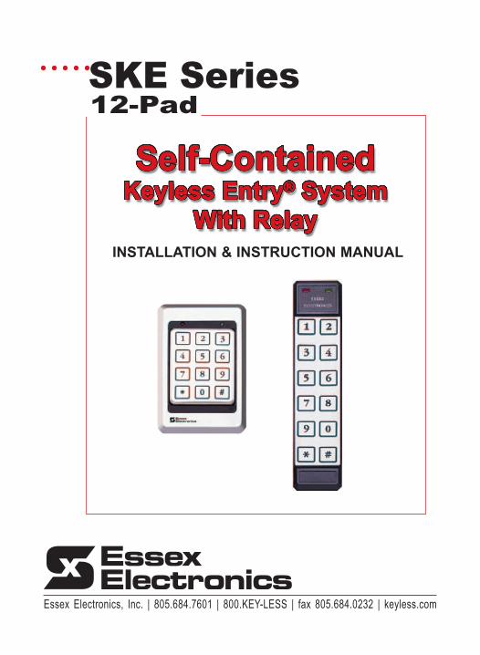
Internal Relay Wiring Diagram
12-24VDCPowerSupply
RED
BLACKYELLOW
BLUE
VIOLETGRAY
FAILSECURE
FAILSAFE
MOV
KEYPAD
12-24VDCPowerSupply
VIOLET
YELLOWBLACK
RED
BLUE
KEY
D
PA
AcrossExistingPushButton
TYPICAL LOCK HOOK-UP TYPICAL GARAGE DOORor GATE HOOK-UP
+
-
+
-MOV
TAN Earth Ground TAN Earth Ground
5Essex Electronics, Inc. | 805.684.7601 | 800.KEY-LESS | fax 805.684.0232 | keyless.com
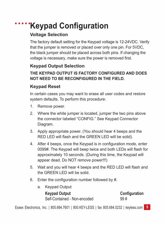
Keypad ConfigurationVoltage SelectionThe factory default setting for the Keypad voltage is 12-24VDC. Verify that the jumper is removed or placed over only one pin. For 5VDC, the black jumper should be placed across both pins. If changing the voltage is necessary, make sure the power is removed first.
Keypad Output Selection ThE KEyPAD OUTPUT IS fACTORy CONfIGURED AND DOES nOT nEED TO BE RECOnfIguRED In ThE fIELD.
Keypad ResetIn certain cases you may want to erase all user codes and restore system defaults. To perform this procedure:
1. Remove power.
2. Where the white jumper is located, jumper the two pins above the connector labeled “CONFIG.” See Keypad Connector Diagram.
3. Apply appropriate power. (You should hear 4 beeps and the RED LED will flash and the GREEN LED will be solid).
4. After 4 beeps, once the Keypad is in configuration mode, enter 0099#. The Keypad will beep twice and both LEDs will flash for approximately 10 seconds. (During this time, the Keypad will appear dead. Do NOT remove power!!!)
5. Wait and you will hear 4 beeps and the RED LED will flash and the GREEN LED will be solid.
6. Enter the configuration number followed by #.
a. Keypad Output KeypadOutput Configuration Self-Contained - Non-encoded 99 #
Essex Electronics, Inc. | 805.684.7601 | 800.KEY-LESS | fax 805.684.0232 | keyless.com6
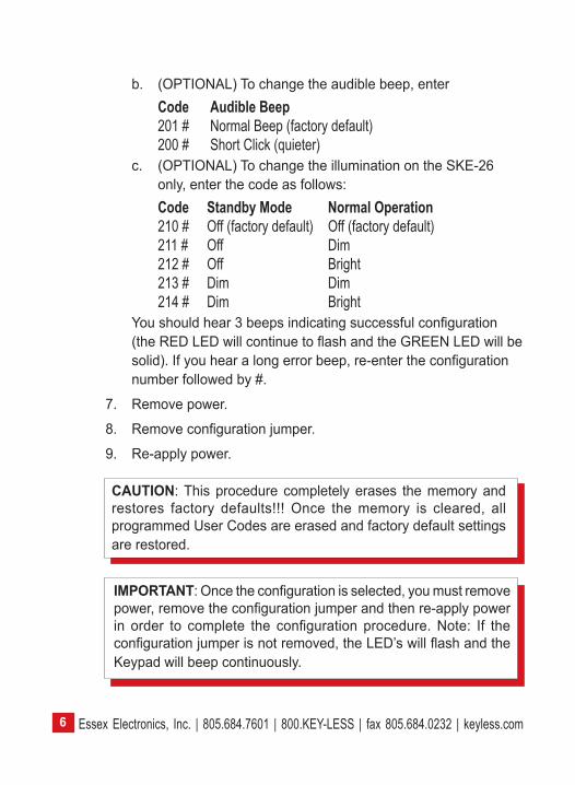
IMPORTAnT: Once the configuration is selected, you must remove power, remove the configuration jumper and then re-apply power in order to complete the configuration procedure. Note: If the configuration jumper is not removed, the LED’s will flash and the Keypad will beep continuously.
CAUTION: This procedure completely erases the memory and restores factory defaults!!! Once the memory is cleared, all programmed User Codes are erased and factory default settings are restored.
b. (OPTIONAL) To change the audible beep, enter Code AudibleBeep 201 # Normal Beep (factory default) 200 # Short Click (quieter)
c. (OPTIONAL) To change the illumination on the SKE-26 only, enter the code as follows:
Code StandbyMode NormalOperation 210 # Off (factory default) Off (factory default) 211 # Off Dim 212 # Off Bright 213 # Dim Dim 214 # Dim Bright
You should hear 3 beeps indicating successful configuration (the RED LED will continue to flash and the GREEN LED will be solid). If you hear a long error beep, re-enter the configuration number followed by #.
7. Remove power.
8. Remove configuration jumper.
9. Re-apply power.
7Essex Electronics, Inc. | 805.684.7601 | 800.KEY-LESS | fax 805.684.0232 | keyless.com
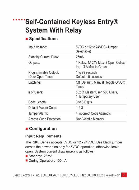
Self-Contained Keyless Entry® System With Relay Specifications
Input Voltage: 5VDC or 12 to 24VDC (Jumper Selectable)Standby Current Draw: 25mAOutputs: 1 Relay, 1A 24V Max; 2 Open Collec-
tor, 1/4 A Max to GroundProgrammable Output: 1 to 99 seconds (Door Open Time) Default - 5 secondsLatching: Off (Default), Manual (Toggle On/Off) Timed# of Users: 502 (1 Master User, 500 Users, 1 Temporary UserCode Length: 3 to 8 DigitsDefault Master Code: 1-2-3Tamper Alarm: 4 Incorrect Code AttemptsAccess Code Protection: Non-Volatile Memory
Configuration
Input RequirementsThe SKE Series accepts 5VDC or 12 - 24VDC. Use black jumper across the power pins only for 5VDC operation, otherwise leave open. System current draw (max) is as follows: Standby: 25mA During Operation: 100mA
Essex Electronics, Inc. | 805.684.7601 | 800.KEY-LESS | fax 805.684.0232 | keyless.com8
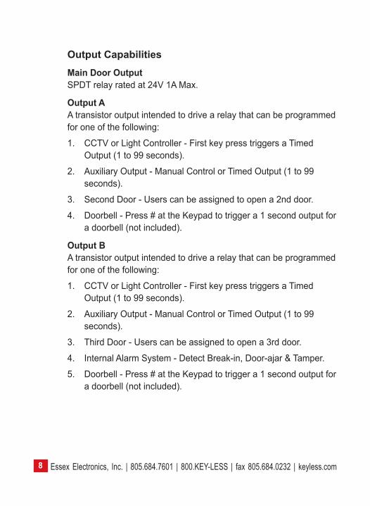
Output CapabilitiesMain Door OutputSPDT relay rated at 24V 1A Max.
Output AA transistor output intended to drive a relay that can be programmed for one of the following:
1. CCTV or Light Controller - First key press triggers a Timed Output (1 to 99 seconds).
2. Auxiliary Output - Manual Control or Timed Output (1 to 99 seconds).
3. Second Door - Users can be assigned to open a 2nd door.
4. Doorbell - Press # at the Keypad to trigger a 1 second output for a doorbell (not included).
Output BA transistor output intended to drive a relay that can be programmed for one of the following:
1. CCTV or Light Controller - First key press triggers a Timed Output (1 to 99 seconds).
2. Auxiliary Output - Manual Control or Timed Output (1 to 99 seconds).
3. Third Door - Users can be assigned to open a 3rd door.
4. Internal Alarm System - Detect Break-in, Door-ajar & Tamper.
5. Doorbell - Press # at the Keypad to trigger a 1 second output for a doorbell (not included).
9Essex Electronics, Inc. | 805.684.7601 | 800.KEY-LESS | fax 805.684.0232 | keyless.com
Programming OverviewThere are two programming commands used with the SKE 12-Pad Self-Contained Keyless Entry® System.
*3 is the Programming System Setup (page 10).This programming command allows the programming of the Master Code, setting the main relay opening time, allows latching (toggling) of the main relay, etc.
*1 is the Programming Command for programming user codes (page 16). When programming the user codes, you have the ability to assign users authorizations. You can authorize a user to latch (if the system was set up to latch in the *3 programming sequence), you can allow a user to program or delete codes or activate one of the other outputs, etc.
The SKE-12 Pad is configured at the factory. Under normal installation, there is no need to Configure or Reset the keypad unless the Beeper needs to be quieter or the Illumination needs to be activated on the SKE-26 only.
The Default Master Code is: 1 2 3The Relay On Time is: 5 sec
Essex Electronics, Inc. | 805.684.7601 | 800.KEY-LESS | fax 805.684.0232 | keyless.com10
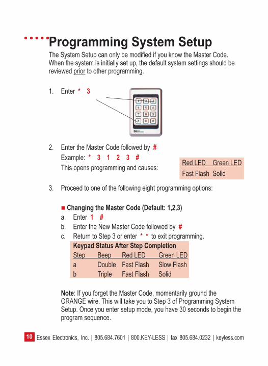
Programming System SetupThe System Setup can only be modified if you know the Master Code. When the system is initially set up, the default system settings should be reviewed prior to other programming.
1. Enter * 3
2. Enter the Master Code followed by # Example: * 3 1 2 3 # This opens programming and causes:
3. Proceed to one of the following eight programming options:
ChangingtheMasterCode(Default:1,2,3)a. Enter 1 #b. Enter the New Master Code followed by #c. Return to Step 3 or enter * * to exit programming.
KeypadStatusAfterStepCompletionStep Beep Red LED Green LEDa Double Fast Flash Slow Flashb Triple Fast Flash Solid
Note: If you forget the Master Code, momentarily ground the ORANGE wire. This will take you to Step 3 of Programming System Setup. Once you enter setup mode, you have 30 seconds to begin the program sequence.
Red LED Green LEDFast Flash Solid
11Essex Electronics, Inc. | 805.684.7601 | 800.KEY-LESS | fax 805.684.0232 | keyless.com
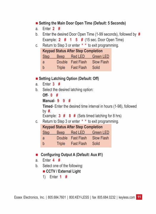
SettingtheMainDoorOpenTime(Default:5Seconds)a. Enter 2 #b. Enter the desired Door Open Time (1-99 seconds), followed by # Example: 2#15# (15 sec. Door Open Time)c. Return to Step 3 or enter * * to exit programming.
KeypadStatusAfterStepCompletionStep Beep Red LED Green LEDa Double Fast Flash Slow Flashb Triple Fast Flash Solid
SettingLatchingOption(Default:Off)a. Enter 3 #b. Select the desired latching option: Off- 0 # Manual- 9 9 # Timed- Enter the desired time interval in hours (1-98), followed by #. Example: 3 # 8 # (Sets timed latching for 8 hrs)c. Return to Step 3 or enter * * to exit programming.
KeypadStatusAfterStepCompletionStep Beep Red LED Green LEDa Double Fast Flash Slow Flashb Triple Fast Flash Solid
ConfiguringOutputA(Default:Aux#1)a. Enter 4 #b. Select one of the following:
CCTV/ExternalLight1) Enter 1 #
Essex Electronics, Inc. | 805.684.7601 | 800.KEY-LESS | fax 805.684.0232 | keyless.com12
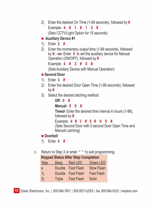
2) Enter the desired On Time (1-99 seconds), followed by #Example: 4#1#15# (Sets CCTV/Light Option for 15 seconds)
AuxiliaryDevice#11) Enter 2 #2) Enter the momentary output time (1-99 seconds), followed
by # ; -or- Enter 0 to set the auxiliary device for Manual Operation (ON/OFF), followed by #
Example: 4 # 2 # 0 # (Sets Auxiliary Device with Manual Operation) SecondDoor1) Enter 3 #2) Enter the desired Door Open Time (1-99 seconds), followed
by #3) Select the desired latching method:
Off- 0 #Manual- 9 9 #Timed- Enter the desired time interval in hours (1-98), followed by #Example: 4#3#5#99# (Sets Second Door with 5 second Door Open Time and Manual Latching)
Doorbell1) Enter 4 #
c. Return to Step 3 or enter * * to exit programming. KeypadStatusAfterStepCompletion
Step Beep Red LED Green LEDa Double Fast Flash Slow Flash1) Double Fast Flash Fast Flash2) Triple Fast Flash Solid
13Essex Electronics, Inc. | 805.684.7601 | 800.KEY-LESS | fax 805.684.0232 | keyless.com
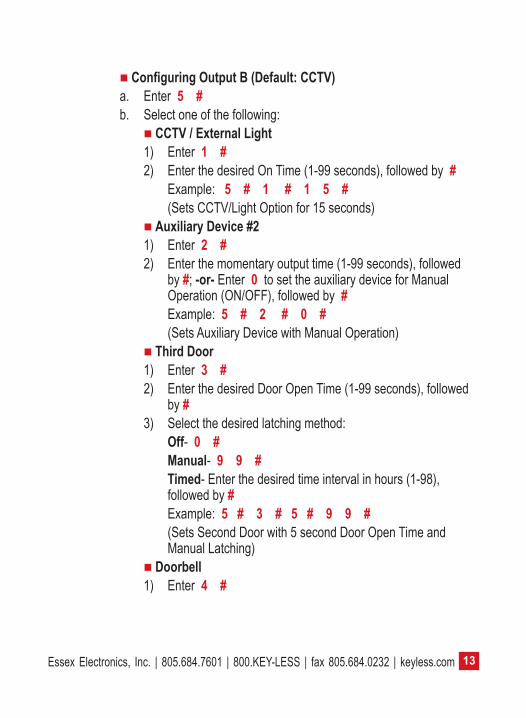
ConfiguringOutputB(Default:CCTV)a. Enter 5#b. Select one of the following:
CCTV/ExternalLight1) Enter 1 #2) Enter the desired On Time (1-99 seconds), followed by #
Example: 5#1#15# (Sets CCTV/Light Option for 15 seconds)
AuxiliaryDevice#21) Enter 2 #2) Enter the momentary output time (1-99 seconds), followed
by #; -or- Enter 0 to set the auxiliary device for Manual Operation (ON/OFF), followed by #Example: 5#2#0# (Sets Auxiliary Device with Manual Operation)
ThirdDoor1) Enter 3 #2) Enter the desired Door Open Time (1-99 seconds), followed
by #3) Select the desired latching method:
Off- 0 #Manual- 9 9 #Timed- Enter the desired time interval in hours (1-98), followed by #Example: 5#3#5#99# (Sets Second Door with 5 second Door Open Time and Manual Latching)
Doorbell1) Enter 4 #
Essex Electronics, Inc. | 805.684.7601 | 800.KEY-LESS | fax 805.684.0232 | keyless.com14
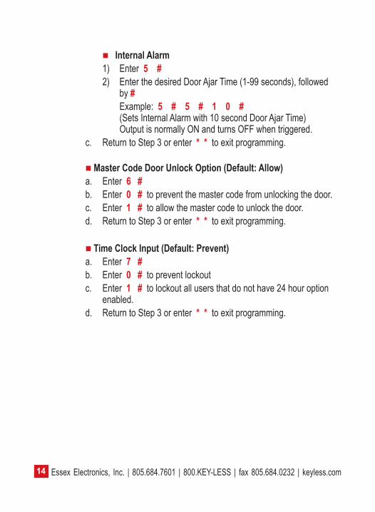
InternalAlarm1) Enter 5#2) Enter the desired Door Ajar Time (1-99 seconds), followed
by #Example: 5#5#10# (Sets Internal Alarm with 10 second Door Ajar Time) Output is normally ON and turns OFF when triggered.
c. Return to Step 3 or enter * * to exit programming.
MasterCodeDoorUnlockOption(Default:Allow)a. Enter 6 #b. Enter 0 # to prevent the master code from unlocking the door.c. Enter 1 # to allow the master code to unlock the door.d. Return to Step 3 or enter * * to exit programming.
TimeClockInput(Default:Prevent)a. Enter 7 #b. Enter 0 # to prevent lockoutc. Enter 1 # to lockout all users that do not have 24 hour option enabled.d. Return to Step 3 or enter * * to exit programming.
15Essex Electronics, Inc. | 805.684.7601 | 800.KEY-LESS | fax 805.684.0232 | keyless.com
Normal System Operation Keypad LED Status Indicators A solid green LED indicates that the door is unlocked. A solid red LED indicates that the door is locked.
Depending on how the System Options are configured, User Commands are used to operate Manual Latching and Auxiliary Outputs. The User Commands are trailing digits entered after an authorized user code followed by #. The ability to use these User Commands depends on authorizations assigned to each User (see Programming Individual Users, page 16).
As the Main Output activates, the green LED will flash for 5 seconds. While the green LED is flashing, enter one (or more) of the following User Commands:
0 # to Latch the Door Closed (Main Relay, 2nd Door or 3rd Door) 1 # to Latch the Door Open (Main Relay, 2nd Door or 3rd Door) 2 # to Turn Output A OFF (2nd Output as Aux.) 3 # to Turn Output A ON (2nd Output as Aux.)4 # to Turn Output B OFF (3rd Output as Aux.)5 # to Turn Output B ON (3rd Output as Aux.)
Tamper AlarmAn audible Tamper Alarm sounds when four incorrect code entries are made. After 30 seconds, the unit returns to standby mode.
Essex Electronics, Inc. | 805.684.7601 | 800.KEY-LESS | fax 805.684.0232 | keyless.com16
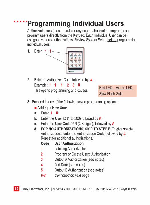
Programming Individual UsersAuthorized users (master code or any user authorized to program) can program users directly from the Keypad. Each Individual User can be assigned various authorizations. Review System Setup before programming individual users.1. Enter * 1
2. Enter an Authorized Code followed by #Example: * 1 1 2 3 #This opens programming and causes:
3. Proceed to one of the following seven programming options:
AddingaNewUsera. Enter 1 #b. Enter the User ID (1 to 500) followed by #c. Enter the User Code/PIN (3-8 digits), followed by #d. FORNOAUTHORIZATIONS,SKIPTOSTEPE. To give special
Authorizations, enter the Authorization Code, followed by #. Repeat for additional authorizations.Code UserAuthorization1 Latching Authorization2 Program or Delete Users Authorization3 Output A Authorization (see notes)4 2nd Door (see notes)5 Output B Authorization (see notes)6-7 Continued on next page
Red LED Green LEDSlow Flash Solid
17Essex Electronics, Inc. | 805.684.7601 | 800.KEY-LESS | fax 805.684.0232 | keyless.com
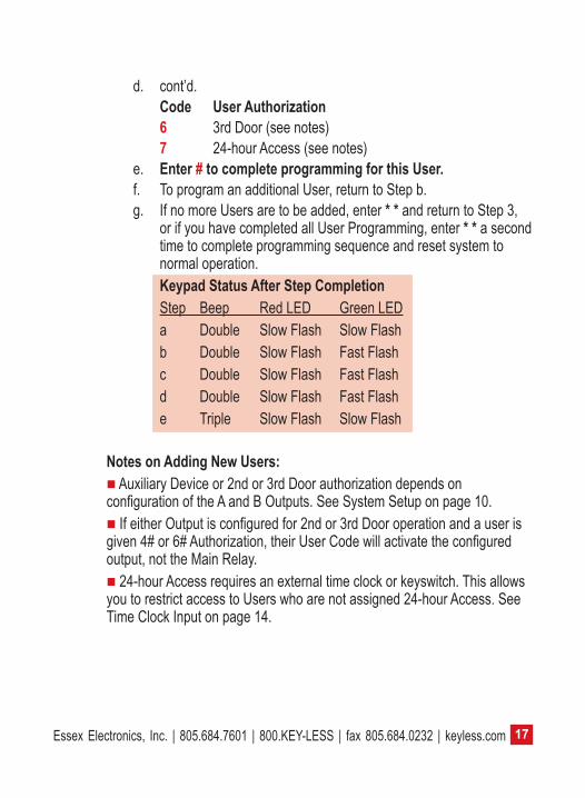
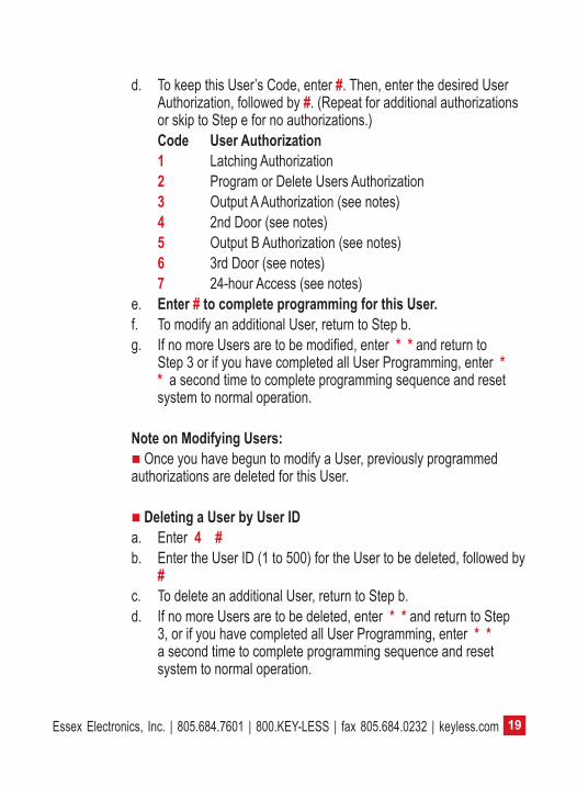
d. cont’d.Code UserAuthorization6 3rd Door (see notes)7 24-hour Access (see notes)
e. Enter#tocompleteprogrammingforthisUser.f. To program an additional User, return to Step b.g. If no more Users are to be added, enter * * and return to Step 3,
or if you have completed all User Programming, enter * * a second time to complete programming sequence and reset system to normal operation.KeypadStatusAfterStepCompletionStep Beep Red LED Green LEDa Double Slow Flash Slow Flashb Double Slow Flash Fast Flashc Double Slow Flash Fast Flashd Double Slow Flash Fast Flashe Triple Slow Flash Slow Flash
NotesonAddingNewUsers: Auxiliary Device or 2nd or 3rd Door authorization depends on configuration of the A and B Outputs. See System Setup on page 10. If either Output is configured for 2nd or 3rd Door operation and a user is given 4# or 6# Authorization, their User Code will activate the configured output, not the Main Relay. 24-hour Access requires an external time clock or keyswitch. This allows you to restrict access to Users who are not assigned 24-hour Access. See Time Clock Input on page 14.
Essex Electronics, Inc. | 805.684.7601 | 800.KEY-LESS | fax 805.684.0232 | keyless.com18
ModifyaUserbyUserIDa. Enter 2 #b. Enter the User ID (1 to 500) for the User to be modified, followed
by #c. To change this User’s Code, enter the New User Code followed by
#-OR,seestepdbelow-d. To keep this User’s Code, enter #. Then, enter the desired User
Authroization, followed by #. (Repeat for additional authorizations or skip to Step e for no authorizations.)Code UserAuthorization1 Latching Authorization2 Program or Delete Users Authorization3 Output A Authorization (see notes)4 2nd Door (see notes)5 Output B Authorization (see notes)6 3rd Door (see notes)7 24-hour Access (see notes)
e. Enter#tocompleteprogrammingforthisUser.f. To modify an additional User, return to Step b.g. If no more Users are to be modified, enter * * and return to Step
3, or if you have completed all User Programming, enter * * a second time to complete programming sequence and reset system to normal operation.
ModifyaUserbyUserCodea. Enter 3 #b. Enter the User Code for the User you wish to modify, followed
by #c. To change this User’s Code, enter the New User Code followed by
#-OR,seestepdonnextpage-
19Essex Electronics, Inc. | 805.684.7601 | 800.KEY-LESS | fax 805.684.0232 | keyless.com
d. To keep this User’s Code, enter #. Then, enter the desired User Authorization, followed by #. (Repeat for additional authorizations or skip to Step e for no authorizations.)Code UserAuthorization1 Latching Authorization2 Program or Delete Users Authorization3 Output A Authorization (see notes)4 2nd Door (see notes)5 Output B Authorization (see notes)6 3rd Door (see notes)7 24-hour Access (see notes)
e. Enter#tocompleteprogrammingforthisUser.f. To modify an additional User, return to Step b.g. If no more Users are to be modified, enter * * and return to
Step 3 or if you have completed all User Programming, enter * * a second time to complete programming sequence and reset system to normal operation.
NoteonModifyingUsers: Once you have begun to modify a User, previously programmed authorizations are deleted for this User.
DeletingaUserbyUserIDa. Enter 4 #b. Enter the User ID (1 to 500) for the User to be deleted, followed by
#c. To delete an additional User, return to Step b.d. If no more Users are to be deleted, enter * * and return to Step
3, or if you have completed all User Programming, enter * * a second time to complete programming sequence and reset system to normal operation.
Essex Electronics, Inc. | 805.684.7601 | 800.KEY-LESS | fax 805.684.0232 | keyless.com20
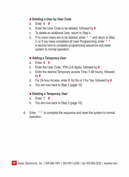
DeletingaUserbyUserCodea. Enter 5#b. Enter the User Code to be deleted, followed by #c. To delete an additional User, return to Step b.d. If no more Users are to be deleted, enter * * and return to Step
3, or if you have completed all User Programming, enter * * a second time to complete programming sequence and reset system to normal operation.
AddingaTemporaryUsera. Enter 6 #b. Enter the User Code / PIN (3-8 digits), followed by #c. Enter the desired Temporary access Time (1-99 hours), followed
by #d. For 24-hour Access, enter 0 for No or 1 for Yes, followed by #e. You are now back to Step 3 (page 16).
DeletingaTemporaryUsera. Enter 7 #b. You are now back to Step 3 (page 16).
4. Enter * * to complete the sequence and reset the system to normal operation.

21Essex Electronics, Inc. | 805.684.7601 | 800.KEY-LESS | fax 805.684.0232 | keyless.com
Notes

Essex Electronics, Inc. | 805.684.7601 | 800.KEY-LESS | fax 805.684.0232 | keyless.com22
Notes

23Essex Electronics, Inc. | 805.684.7601 | 800.KEY-LESS | fax 805.684.0232 | keyless.com
Notes
Essex Electronics, Inc. | 805.684.7601 | 800.KEY-LESS | fax 805.684.0232 | keyless.com24
Warranty & Repairs General Warranty Policy (effective date May 1, 2014)
Essex Electronics Inc. (“Essex”) warrants that at the time of original purchase from Essex the products specified below are free from defects in workmanship and material. Subject to the conditions and limitations set forth below, Essex will, at its option, either repair or replace any part of its products that prove defective by reason of improper workmanship or materials. Repaired parts or replacement products will be provided by Essex on an exchange basis, and will be either new or refurbished to be functionally equivalent to new. Essex reserves the right to discontinue a product for any reason, without notice, at any time. If a product that has been discontinued proves defective and if Essex is unable to repair or replace the product, within the terms expressed in this Limited Warranty, a substitute product may be provided at Essex’s election, as a replacement for the original discontinued product.
This Limited Warranty extends only to the original retail or wholesale Buyer and the original site of installation. It does not cover any damage to this product or parts thereof, if the product is installed in violation of the applicable codes or ordinances, or is not installed and used in accordance with our installation instructions. This warranty applies only to standard Essex products purchased as completed assemblies and does not cover custom products (excluding custom graphics) nor does it cover products purchased as subassemblies. This warranty will only include the normal operating life of the LED’s and relays as specified by the manufacturer. It does not cover any damage that results from accident, abuse, misuse, natural disaster, insufficient or excessive electrical supply, abnormal mechanical or environmental conditions, or any unauthorized disassembly, repair, or modification. This Limited Warranty also does not apply to any product on which the original identification or date of manufacture information has been

25Essex Electronics, Inc. | 805.684.7601 | 800.KEY-LESS | fax 805.684.0232 | keyless.com
altered, obliterated or removed. In no event shall Essex be liable for any damage to persons, property or area surrounding the installation site caused by any malfunction of the product manufactured or supplied by Essex.
Essex will not pay, nor be responsible for shipping, transportation or delivery charges, or other cost of removal of a defective product or installation of a replacement product. The original component replaced under this Limited Warranty in any system shall become the property of Essex and as such will, at our request, be returned to our factory with transportation charges paid by the Buyer.
Limited Lifetime Warranty: Products carrying Limited Lifetime Warranty against defects in materials and workmanship are Essex KTP Series Keypads, K1 Series, SKE Series Keypads, KE-265 Series, PEB Series and Hand-E-Tap Series Door Access Switches. Only products with a manufactured date of 5/1/06 to the present date are covered by this Limited Lifetime Warranty.
Limited 18 Month Warranty: Products carrying an 18 month warranty against defects in materials and workmanship include External Power Supplies, Hand-E-Wave™, HID Edge® controllers, products with embedded 125 kHz and 13.56 MHz Card Reader processors including the PiezoProx®, iSMART™, K-Prox, RoxProx™, RoxClass™, T-Prox™, iRox™ and iRox Plus™.
Limited 3 year Warranty: Essex KE-1700 Series and AKE-5 Series are covered by a 3 year limited warranty against defects in materials and workmanship.
Limited 2 year Warranty: Essex products used for Elevator access control applications are covered by a 2 year limited warranty. This includes the KE-1000, KE-1900 and SKE-34 used in an elevator access control installation.
Essex Electronics, Inc.’s liability and Buyer’s remedy under this warranty is limited to the repair or replacement at Seller’s election
Essex Electronics, Inc. | 805.684.7601 | 800.KEY-LESS | fax 805.684.0232 | keyless.com26
of the product, or parts thereof, returned to Essex Electronics Inc. at Buyer’s expense and shown to Essex Electronics Inc.’s reasonable satisfaction to have been defective.
Notice of any defect must be sent in writing to Essex Electronics, Inc., 1130 Mark Avenue, Carpinteria, California, 93013, USA and must include the date code of the unit, description of the defect and factory assigned Return Authorization #. Upon receipt of such notification, Essex will determine whether to repair or replace. We also reserve the right to have our representative make any inspection or repairs, or furnish replacements.
ESSEX RESERVES ThE RIghT TO AMEnD ThIS gEnERAL WARRAnTY POLICY AS REQuIRED.
Disclaimer of Warranties: Limitation of Buyer’s RemediesExcept for the repair or replacement at seller’s option which is expressly set forth above, Essex Electronics Inc. extends no warranty of any kind, express or implied, and disclaims any implied warranty of merchantability or suitability for purpose for which sold, with respect to the keypads, keyless entry coded access system or accessories. Except for the limited repair or replacement specified above, under no circumstances will Essex Electronics Inc. be liable to buyer under or in connection with any manufacture or sale of any of the products set forth above under any tort, negligence, strict liability, contract or other legal or equitable theory, or for incidental or consequential damages, or buyer’s cost of effecting insurance coverage.
The foregoing limited warranty expressed herein constitutes the sole and entire warranty with respect to the products set forth above and is in place of any and all other warranties, express or implied.
This warranty may not be expanded or extended by any oral representation, written sales information, advertising, drawings or otherwise. Essex Electronics Inc. is not responsible hereunder for incidental damage to person or property, or other incidental or
27Essex Electronics, Inc. | 805.684.7601 | 800.KEY-LESS | fax 805.684.0232 | keyless.com
consequential damages. The remedies of the buyer shall be limited to those provided in this limited lifetime warranty to the exclusion of any and all other remedies, including, without limitation, incidental or consequential damages.
This Limited Lifetime Warranty shall be governed by and interpreted in accordance with the California Uniform Commercial Code and by the procedural laws of the State of California. Any lawsuit or other action which arises out of, relates to, or is in connection with the manufacture or sale of the products set forth above shall be governed by California law, and the venue for any such action shall be the Superior Court of the State of California in and for Santa Barbara County, California. Repair PolicyShould it be necessary for a component or a system to be returned for repair, it must be accompanied with an RA# (Return Authorization Number) issued by the factory. Please call 1-800-KEYLESS (800-539-5377) to obtain an RA#. All returns must be sent to the factory freight prepaid. Collect shipments will not be accepted at any time. Standard turnaround time is ten (10) working days from the date of receipt. Repaired components will be returned UPS Ground (or equivalent). Any other shipping requests or instructions will be at the customer’s expense.At the factory’s discretion, warranty repairs will include repair or replacement, update and testing. Returns and repairs out of the warranty period or in warranty with damage not covered under warranty shall be subject to a repair charge. All non-warranty repair freight charges are paid for by the customer. Non-warranty repair charges must be paid by credit card. (Factory Authorized Distributors are subject to standard terms).

Essex Electronics, Inc. | 805.684.7601 | 800.KEY-LESS | fax 805.684.0232 | keyless.com