Embed Size (px)
Citation preview
Turbo-Like Coding for Spread-Spectrum
Communications
A ThesisPresented to
The Academic Faculty
by
Hasung Kim
In Partial Fulfillmentof the Requirements for the Degree
Doctor of Philosophy
School of Electrical and Computer EngineeringGeorgia Institute of Technology
September 2004
Turbo-Like Coding for Spread-Spectrum
Communications
Approved by:
Professor Gordon L. Stuber, Advisor
Professor Nikil S. Jayant
Professor Ye (Geoffrey) Li
Professor Faramarz Fekri
Professor Alfred D. AndrewSchool of Mathematics
Date Approved: September 16, 2004

To my parents, Sungkoo Kim and Dukhwa Jung, and my wife, Youngwon Kim, without
who I would not be at this point in my life.
iii

ACKNOWLEDGEMENTS
I would like to express my deep appreciation to my advisor, Dr. Gordon Stuber. His
guidance and expertise was invaluable to me during my graduate study. I would also like to
thank the remaining members of my thesis committee, Dr. Nikil Jayant, Dr. Ye (Geoffrey)
Li, Dr. Faramarz Fekri, and Dr. Alfred Andrew for their interest and input into my reseach.
Their thoughtful advice and encouragement was greatly treasured.
I would like to thank current and previous labmates of Wireless Systems Laboratory
including Wajih Abu-Al-Saud, Galib Asadullah, Jinsoup Jung, Heewon Kang, Dukhyun
Kim, Joonbeom Kim, Kihong Kim, John Kim, Apurva Mody, Krishna Narayanan, Jun
Tan, and Qing Zhao, and colleagues of Telecom group including who discussed with me
about research and provided a fun and enjoyable environment to work.
Finally, I am especially grateful to my beloved wife, Youngwon Kim, and my parents,
Sungkoo Kim and Dukhwa Jung, for providing me with enduring love, unselfish sacrifice,
and heartful encouragement throughout my life and opportunity to fulfill all of my academic
endeavors.
iv
TABLE OF CONTENTS
DEDICATION . . . . . . . . . . . . . . . . . . . . . . . . . . . . . . . . . . . . . . iii
ACKNOWLEDGEMENTS . . . . . . . . . . . . . . . . . . . . . . . . . . . . . . iv
LIST OF TABLES . . . . . . . . . . . . . . . . . . . . . . . . . . . . . . . . . . . ix
LIST OF FIGURES . . . . . . . . . . . . . . . . . . . . . . . . . . . . . . . . . . x
LIST OF ABBREVIATIONS . . . . . . . . . . . . . . . . . . . . . . . . . . . . . xiii
SUMMARY . . . . . . . . . . . . . . . . . . . . . . . . . . . . . . . . . . . . . . . . xvi
CHAPTER I INTRODUCTION . . . . . . . . . . . . . . . . . . . . . . . . . 1
1.1 Motivations . . . . . . . . . . . . . . . . . . . . . . . . . . . . . . . . . . . 1
1.2 Outline of the Thesis . . . . . . . . . . . . . . . . . . . . . . . . . . . . . . 3
CHAPTER II BACKGROUND . . . . . . . . . . . . . . . . . . . . . . . . . . 4
2.1 Turbo-Like Codes and Iterative Decoding . . . . . . . . . . . . . . . . . . . 4
2.1.1 Turbo-Like Codes . . . . . . . . . . . . . . . . . . . . . . . . . . . . 4
2.1.2 Turbo-Like Coded Modulations . . . . . . . . . . . . . . . . . . . . 6
2.1.3 SISO Iterative Decoding . . . . . . . . . . . . . . . . . . . . . . . . 8
2.2 Adaptive Turbo-Like Coding and Hybrid-ARQ . . . . . . . . . . . . . . . . 9
2.2.1 Adaptive Error Control Systems . . . . . . . . . . . . . . . . . . . . 9
2.2.2 Hybrid-ARQ Schemes . . . . . . . . . . . . . . . . . . . . . . . . . . 10
2.2.3 Rate Compatible Punctured Codes . . . . . . . . . . . . . . . . . . 13
2.3 Analysis of Turbo-Like Codes . . . . . . . . . . . . . . . . . . . . . . . . . 15
2.3.1 ML Decoding Bounds and Distance Spectrum . . . . . . . . . . . . 15
2.3.2 Density Evolution and Convergence Analysis . . . . . . . . . . . . . 19
2.4 Spread-Spectrum Communications . . . . . . . . . . . . . . . . . . . . . . 21
2.4.1 W-CDMA System . . . . . . . . . . . . . . . . . . . . . . . . . . . . 21
2.4.2 DS and FH Systems for Anti-Jamming . . . . . . . . . . . . . . . . 23
CHAPTER III DIRECT-SEQUENCE CONCATENATED CODED CPM 25
3.1 System Model . . . . . . . . . . . . . . . . . . . . . . . . . . . . . . . . . . 26
3.1.1 Transmitter Structure . . . . . . . . . . . . . . . . . . . . . . . . . 26
v
3.1.2 Anti-Jam Iterative Receiver . . . . . . . . . . . . . . . . . . . . . . 27
3.1.3 Chip-by-Chip Random Interleaved System . . . . . . . . . . . . . . 28
3.2 Bound Analysis of the Anti-Jamming Performance . . . . . . . . . . . . . 29
3.3 Mixed Concatenated Coded CPM and Convergence Analysis . . . . . . . . 30
3.4 Numerical Results and Discussions . . . . . . . . . . . . . . . . . . . . . . 32
3.4.1 Chip- vs. Block-wise Random Interleaving . . . . . . . . . . . . . . 32
3.4.2 Effect of the Jamming Duty Factor under Pulse Jamming . . . . . 33
3.4.3 Analytical Anti-Jamming Performance . . . . . . . . . . . . . . . . 34
3.4.4 Effect of the Mixture Ratio on the Iterative Receiver . . . . . . . . 37
3.4.5 Effect of the Duty Factor and the Mixture Ratio on the Anti-JammingPerformance . . . . . . . . . . . . . . . . . . . . . . . . . . . . . . . 37
3.4.6 Convergence Analysis on Anti-Jamming Performance . . . . . . . . 39
3.5 Conclusions . . . . . . . . . . . . . . . . . . . . . . . . . . . . . . . . . . . 41
CHAPTER IV SERIALLY CONCATENATED SLOW FH-CPM . . . . . 42
4.1 System Model . . . . . . . . . . . . . . . . . . . . . . . . . . . . . . . . . . 43
4.1.1 Transmitter Structure . . . . . . . . . . . . . . . . . . . . . . . . . 43
4.1.2 Anti-Jam Coherent and Non-Coherent Iterative Receivers . . . . . 45
4.2 Bound Analysis of the Anti-Jamming Performance . . . . . . . . . . . . . 47
4.3 An Iterative Jamming Estimation Technique . . . . . . . . . . . . . . . . . 49
4.4 Numerical Results and Discussions . . . . . . . . . . . . . . . . . . . . . . 50
4.4.1 Effect of the Slow FH Channel on the Anti-Jamming Performance . 52
4.4.2 Anti-Jamming Performance of the Iterative Receivers . . . . . . . . 52
4.4.3 The Worst-Case Jamming Performance for Different Modulation In-dexes and Outer Codes . . . . . . . . . . . . . . . . . . . . . . . . . 53
4.4.4 Anti-Jamming Performance of Jamming Estimation . . . . . . . . . 56
4.4.5 Jamming Estimation for Different Slow FH Parameters . . . . . . . 57
4.4.6 Effect of Outer Channel Codes on Anti-Jamming Performance . . . 58
4.5 Conclusions . . . . . . . . . . . . . . . . . . . . . . . . . . . . . . . . . . . 59
CHAPTER V TURBO-LIKE CODED MULTI-H CPM . . . . . . . . . . . 60
5.1 Turbo-Like Coded Modulation . . . . . . . . . . . . . . . . . . . . . . . . . 61
5.2 Serially Concatenated Multi-h CPM . . . . . . . . . . . . . . . . . . . . . . 61
vi
5.3 Performance Analysis . . . . . . . . . . . . . . . . . . . . . . . . . . . . . . 63
5.3.1 Union-Chernoff Bound . . . . . . . . . . . . . . . . . . . . . . . . . 63
5.3.2 Transfer Function of Multi-h CPM . . . . . . . . . . . . . . . . . . 66
5.3.3 Convergence Analysis Based on Input and Output Extrinsic Infor-mation . . . . . . . . . . . . . . . . . . . . . . . . . . . . . . . . . . 67
5.4 Numerical Results and Discussions . . . . . . . . . . . . . . . . . . . . . . 68
5.4.1 Error Performance on AWGN Channels . . . . . . . . . . . . . . . . 69
5.4.2 Convergence Analysis . . . . . . . . . . . . . . . . . . . . . . . . . . 69
5.4.3 Effect of Fading Correlation on Performance . . . . . . . . . . . . . 70
5.5 Conclusions . . . . . . . . . . . . . . . . . . . . . . . . . . . . . . . . . . . 70
CHAPTER VI TURBO HYBRID-ARQ FOR W-CDMA . . . . . . . . . . 74
6.1 Concatenated RS-Turbo Coded Hybrid-ARQ . . . . . . . . . . . . . . . . . 75
6.2 W-CDMA System with Turbo Hybrid-ARQ . . . . . . . . . . . . . . . . . 77
6.2.1 System Description . . . . . . . . . . . . . . . . . . . . . . . . . . . 77
6.2.2 Channel Estimation and Rake Reciever . . . . . . . . . . . . . . . . 79
6.3 Numerical Results and Discussions . . . . . . . . . . . . . . . . . . . . . . 84
6.3.1 Error and Latency Performances of the Turbo HARQ Scheme . . . 84
6.3.2 Performance in the W-CDMA System . . . . . . . . . . . . . . . . 85
6.4 Conclusions . . . . . . . . . . . . . . . . . . . . . . . . . . . . . . . . . . . 86
CHAPTER VII RATE COMPATIBLE PUNCTURED TURBO-LIKE CODES
88
7.1 Rate Compatible Punctured Turbo Codes . . . . . . . . . . . . . . . . . . 88
7.1.1 Concatenated RS-RCPT Codes . . . . . . . . . . . . . . . . . . . . 89
7.1.2 Puncturing Methods and RCPT-HARQ Protocol . . . . . . . . . . 91
7.1.3 Numerical Results and Discussions . . . . . . . . . . . . . . . . . . 95
7.1.4 Conclusions . . . . . . . . . . . . . . . . . . . . . . . . . . . . . . . 100
7.2 Rate Compatible Punctured SCCC . . . . . . . . . . . . . . . . . . . . . . 101
7.2.1 RCPS Codes and Puncturing Methods . . . . . . . . . . . . . . . . 102
7.2.2 RCPS-HARQ Protocol . . . . . . . . . . . . . . . . . . . . . . . . . 104
7.2.3 Numerical Results and Discussions . . . . . . . . . . . . . . . . . . 105
7.2.4 Conclusions . . . . . . . . . . . . . . . . . . . . . . . . . . . . . . . 109
vii
CHAPTER VIII CONCLUDING REMARKS . . . . . . . . . . . . . . . . . 110
8.1 Summary of Contributions . . . . . . . . . . . . . . . . . . . . . . . . . . . 110
8.2 Suggestions for Future Research . . . . . . . . . . . . . . . . . . . . . . . . 111
APPENDIX A — UNION BOUNDS ON THE PERFORMANCE OF ML
DECODING FOR SCCC . . . . . . . . . . . . . . . . . . . . . . . . . . . . . 113
APPENDIX B — TRANSFER CHARACTERISTICS FOR THE JAM-
MING CHANNEL . . . . . . . . . . . . . . . . . . . . . . . . . . . . . . . . . 117
REFERENCES . . . . . . . . . . . . . . . . . . . . . . . . . . . . . . . . . . . . . 118
VITA . . . . . . . . . . . . . . . . . . . . . . . . . . . . . . . . . . . . . . . . . . . . 127
viii
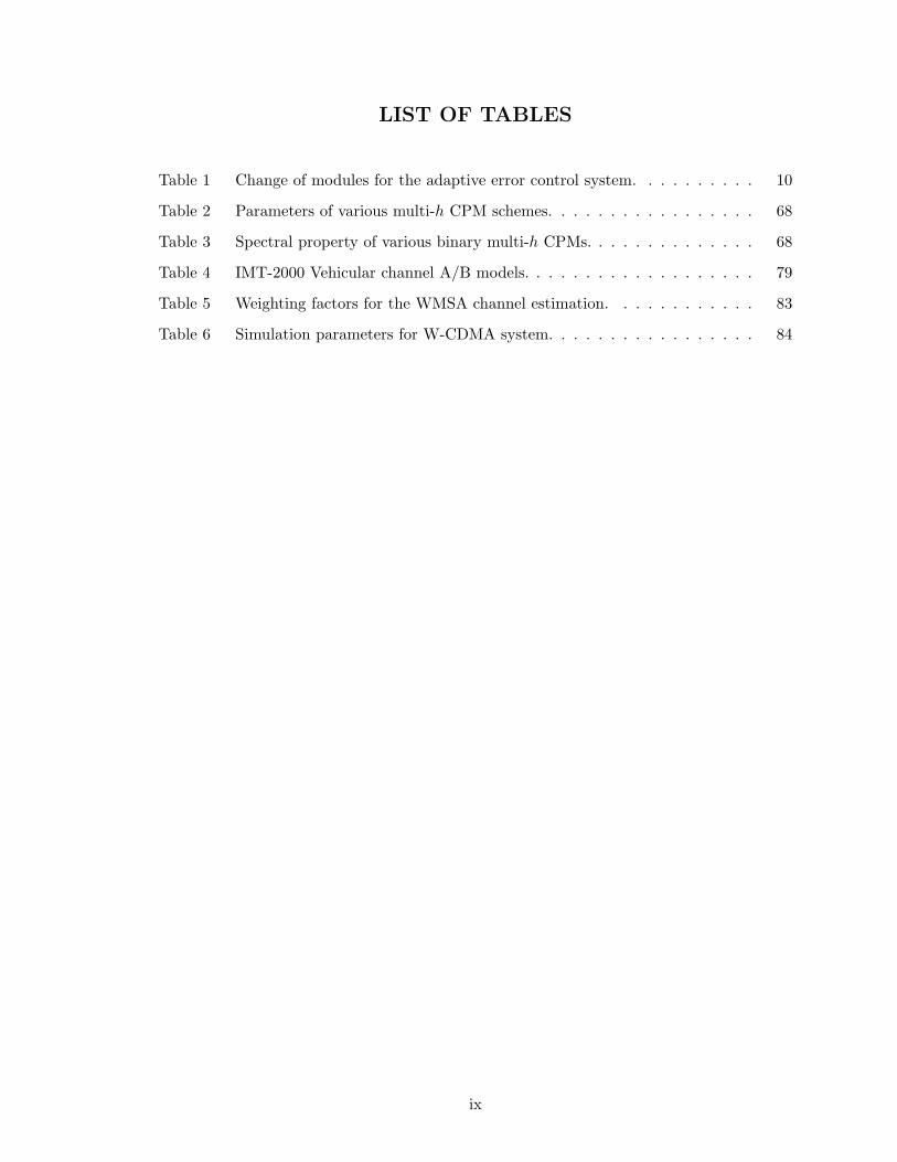
LIST OF TABLES
Table 1 Change of modules for the adaptive error control system. . . . . . . . . . 10
Table 2 Parameters of various multi-h CPM schemes. . . . . . . . . . . . . . . . . 68
Table 3 Spectral property of various binary multi-h CPMs. . . . . . . . . . . . . . 68
Table 4 IMT-2000 Vehicular channel A/B models. . . . . . . . . . . . . . . . . . . 79
Table 5 Weighting factors for the WMSA channel estimation. . . . . . . . . . . . 83
Table 6 Simulation parameters for W-CDMA system. . . . . . . . . . . . . . . . . 84
ix
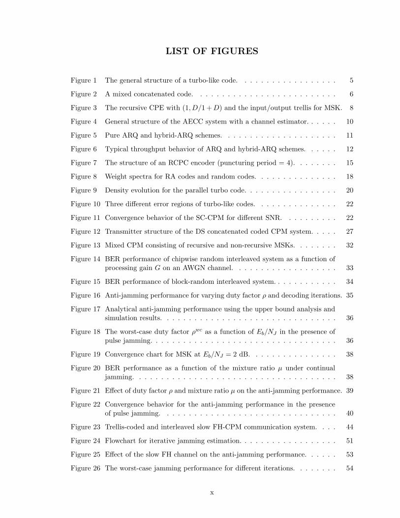
LIST OF FIGURES
Figure 1 The general structure of a turbo-like code. . . . . . . . . . . . . . . . . . 5
Figure 2 A mixed concatenated code. . . . . . . . . . . . . . . . . . . . . . . . . . 6
Figure 3 The recursive CPE with (1, D/1 + D) and the input/output trellis for MSK. 8
Figure 4 General structure of the AECC system with a channel estimator. . . . . . 10
Figure 5 Pure ARQ and hybrid-ARQ schemes. . . . . . . . . . . . . . . . . . . . . 11
Figure 6 Typical throughput behavior of ARQ and hybrid-ARQ schemes. . . . . . 12
Figure 7 The structure of an RCPC encoder (puncturing period = 4). . . . . . . . 15
Figure 8 Weight spectra for RA codes and random codes. . . . . . . . . . . . . . . 18
Figure 9 Density evolution for the parallel turbo code. . . . . . . . . . . . . . . . . 20
Figure 10 Three different error regions of turbo-like codes. . . . . . . . . . . . . . . 22
Figure 11 Convergence behavior of the SC-CPM for different SNR. . . . . . . . . . 22
Figure 12 Transmitter structure of the DS concatenated coded CPM system. . . . . 27
Figure 13 Mixed CPM consisting of recursive and non-recursive MSKs. . . . . . . . 32
Figure 14 BER performance of chipwise random interleaved system as a function ofprocessing gain G on an AWGN channel. . . . . . . . . . . . . . . . . . . 33
Figure 15 BER performance of block-random interleaved system. . . . . . . . . . . . 34
Figure 16 Anti-jamming performance for varying duty factor ρ and decoding iterations. 35
Figure 17 Analytical anti-jamming performance using the upper bound analysis andsimulation results. . . . . . . . . . . . . . . . . . . . . . . . . . . . . . . . 36
Figure 18 The worst-case duty factor ρwc as a function of Eb/NJ in the presence ofpulse jamming. . . . . . . . . . . . . . . . . . . . . . . . . . . . . . . . . . 36
Figure 19 Convergence chart for MSK at Eb/NJ = 2 dB. . . . . . . . . . . . . . . . 38
Figure 20 BER performance as a function of the mixture ratio µ under continualjamming. . . . . . . . . . . . . . . . . . . . . . . . . . . . . . . . . . . . . 38
Figure 21 Effect of duty factor ρ and mixture ratio µ on the anti-jamming performance. 39
Figure 22 Convergence behavior for the anti-jamming performance in the presenceof pulse jamming. . . . . . . . . . . . . . . . . . . . . . . . . . . . . . . . 40
Figure 23 Trellis-coded and interleaved slow FH-CPM communication system. . . . 44
Figure 24 Flowchart for iterative jamming estimation. . . . . . . . . . . . . . . . . . 51
Figure 25 Effect of the slow FH channel on the anti-jamming performance. . . . . . 53
Figure 26 The worst-case jamming performance for different iterations. . . . . . . . 54
x
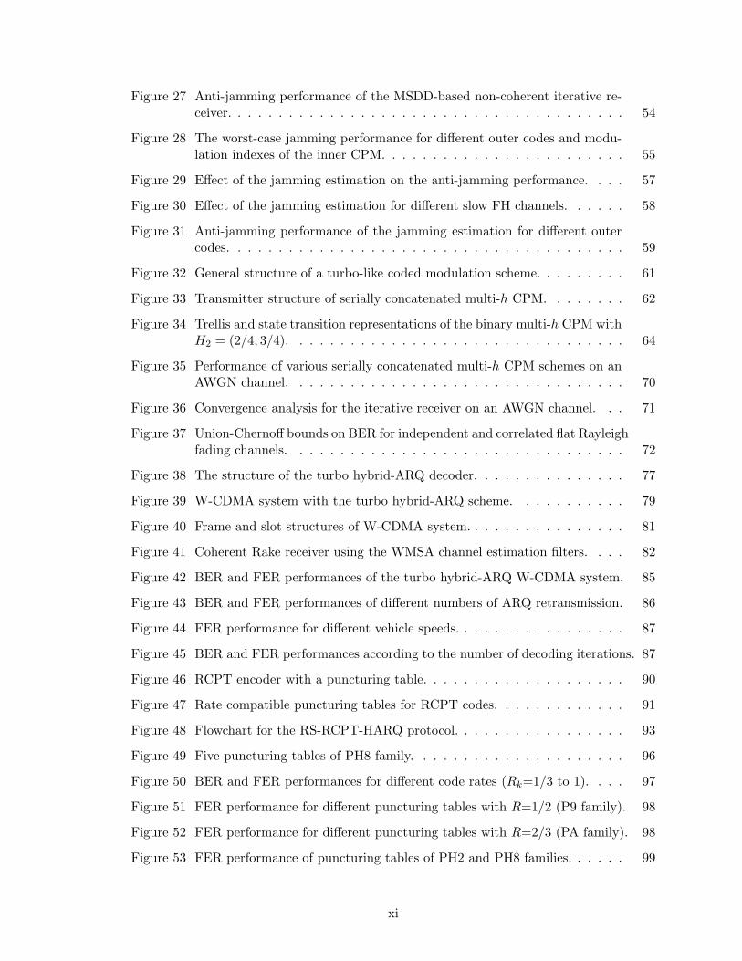
Figure 27 Anti-jamming performance of the MSDD-based non-coherent iterative re-ceiver. . . . . . . . . . . . . . . . . . . . . . . . . . . . . . . . . . . . . . . 54
Figure 28 The worst-case jamming performance for different outer codes and modu-lation indexes of the inner CPM. . . . . . . . . . . . . . . . . . . . . . . . 55
Figure 29 Effect of the jamming estimation on the anti-jamming performance. . . . 57
Figure 30 Effect of the jamming estimation for different slow FH channels. . . . . . 58
Figure 31 Anti-jamming performance of the jamming estimation for different outercodes. . . . . . . . . . . . . . . . . . . . . . . . . . . . . . . . . . . . . . . 59
Figure 32 General structure of a turbo-like coded modulation scheme. . . . . . . . . 61
Figure 33 Transmitter structure of serially concatenated multi-h CPM. . . . . . . . 62
Figure 34 Trellis and state transition representations of the binary multi-h CPM withH2 = (2/4, 3/4). . . . . . . . . . . . . . . . . . . . . . . . . . . . . . . . . 64
Figure 35 Performance of various serially concatenated multi-h CPM schemes on anAWGN channel. . . . . . . . . . . . . . . . . . . . . . . . . . . . . . . . . 70
Figure 36 Convergence analysis for the iterative receiver on an AWGN channel. . . 71
Figure 37 Union-Chernoff bounds on BER for independent and correlated flat Rayleighfading channels. . . . . . . . . . . . . . . . . . . . . . . . . . . . . . . . . 72
Figure 38 The structure of the turbo hybrid-ARQ decoder. . . . . . . . . . . . . . . 77
Figure 39 W-CDMA system with the turbo hybrid-ARQ scheme. . . . . . . . . . . 79
Figure 40 Frame and slot structures of W-CDMA system. . . . . . . . . . . . . . . . 81
Figure 41 Coherent Rake receiver using the WMSA channel estimation filters. . . . 82
Figure 42 BER and FER performances of the turbo hybrid-ARQ W-CDMA system. 85
Figure 43 BER and FER performances of different numbers of ARQ retransmission. 86
Figure 44 FER performance for different vehicle speeds. . . . . . . . . . . . . . . . . 87
Figure 45 BER and FER performances according to the number of decoding iterations. 87
Figure 46 RCPT encoder with a puncturing table. . . . . . . . . . . . . . . . . . . . 90
Figure 47 Rate compatible puncturing tables for RCPT codes. . . . . . . . . . . . . 91
Figure 48 Flowchart for the RS-RCPT-HARQ protocol. . . . . . . . . . . . . . . . . 93
Figure 49 Five puncturing tables of PH8 family. . . . . . . . . . . . . . . . . . . . . 96
Figure 50 BER and FER performances for different code rates (Rk=1/3 to 1). . . . 97
Figure 51 FER performance for different puncturing tables with R=1/2 (P9 family). 98
Figure 52 FER performance for different puncturing tables with R=2/3 (PA family). 98
Figure 53 FER performance of puncturing tables of PH2 and PH8 families. . . . . . 99
xi
Figure 54 Throughput performance of puncturing tables of PH2 and PH8 families. . 99
Figure 55 Encoder structures of SCCC. . . . . . . . . . . . . . . . . . . . . . . . . . 103
Figure 56 Puncturing table for the RCPS codes using the systematic puncturing. . 104
Figure 57 Puncturing tables for the RCPS-HARQ (PTs) and RCPP-HARQ (PTp). 105
Figure 58 FER performance of the SCCC, PCCC, RS-SCCC, and RS-PCCC. AWGNchannel and rate-1/3. . . . . . . . . . . . . . . . . . . . . . . . . . . . . . 106
Figure 59 FER performance of the RCPS and RCPP codes for different code rates.AWGN channel, and rate-1/3, 4/9, and 2/3. . . . . . . . . . . . . . . . . 107
Figure 60 FER performance of the W-CDMA systems with the RCPS and RCPPcodes for different code rates. . . . . . . . . . . . . . . . . . . . . . . . . . 108
Figure 61 FER performance of the RCPS-HARQ (PTs) and RCPP-HARQ (PTp)systems on an AWGN channel. . . . . . . . . . . . . . . . . . . . . . . . . 108
Figure 62 Throughput performance of the RCPS-HARQ (PTs) and RCPP-HARQ(PTp) systems on an AWGN channel. . . . . . . . . . . . . . . . . . . . . 109
xii
LIST OF ABBREVIATIONS
3GPP 3rd generation partnership project
AEC Adaptive error control
AJ Anti-jam
AMC Adaptive modulation and coding
APP a posteriori probability
ARQ Automatic repeat request
AWGN Additive white Gaussian noise
BER Bit error rate
BICM Bit-interleaved coded modulation
BPSK Binary phase-shift keying
CC Convolutional code
CDMA Code division multiple access
COWEF Conditional output weight enumerating function
CPE Continuous phase encoder
CPFSK Continuous phase frequency-shift keying
CPM Continuous phase modulation
CRC Cyclic redundancy check
CSI Channel side information
DE Density evolution
DPSK Differential phase-shift keying
DS Direct-sequence
DSL Digital subscriber line
DVB Digital video broadcasting
FEC Forward error correction
FER Frame error rate
xiii
FH Frequency-hopping
FSK Frequency-shift keying
HARQ Hybrid-ARQ
HSDPA High speed downlink packet access
ID Iterative decoding
IDD Iterative demodulation and decoding
IGE Interleaving gain exponent
IOWEF Input-output weight enumerating function
IP Internet protocol
JSI Jammer state information
LDPC Low-density parity-check
LLR Log-likelihood ratio
LPD Low-probability of detection
LPI Low-probability of intercept
MAI Multiple access interference
MAP Maximum a posteriori
MCC Mixed concatenated code
MHCPM Multi-h CPM
MIMO Multiple-input multiple-output
MIS Modulation index set
ML Maximum-likelihood
MM Memoryless modulator
MNSED Minimum normalized squared Euclidean distance
MSK Minimum-shift keying
OFDM Orthogonal frequency division multiplexing
PBNJ Partial-band noise jamming
PCCC Parallel concatenated convolutional code
PDF Probability density function
PEP Pairwise error probability
xiv
PN Pseudo-noise
PNJ Pulse-noise jamming
QoS Quality of service
QPSK Quadrature phase-shift keying
RA Repeat-accumulate
RCPC Rate compatible punctured convolutional
RCPS Rate compatible punctured SCCC
RCPT Rate compatible punctured turbo
RS Reed-Solomon
RSC Recursive systematic convolutional
SCBC Serially concatenated block code
SCCC Serially concatenated convolutional code
SISO Soft-input soft-output
SNR Signal-to-noise ratio
SOVA Soft-output Viterbi algorithm
SS Spread-spectrum
TLC Turbo-like code
TLCM Turbo-like coded modulation
TPC Turbo product code
UWB Ultra-wideband
W-CDMA Wideband-CDMA
WEF Weight enumerating function
WLAN Wireless local-area-network
xv
SUMMARY
This thesis studies advanced error control schemes using turbo-like codes, turbo-like
coded modulations, turbo hybrid-ARQ (Automatic Repeat reQuest) schemes, and rate
compatible puncturing techniques for reliable and adaptive commercial and tactical spread-
spectrum communications, especially for code-division multiple access (CDMA) cellular
systems and direct-sequence (DS) and frequency-hopping (FH) anti-jam systems. Further-
more, we utilize both the maximum-likelihood (ML) bounding techniques and convergence
analysis to design and analyze various turbo-like coding schemes that show different behav-
iors in error performance from conventional trellis coding schemes.
In the area of DS-CPM, we propose a DS concatenated coded CPM system for pulse-
noise jamming channels and an anti-jam iterative receiver utilizing jammer state informa-
tion. We also design a mixed concatenated CPM system that mixes CPM schemes with
different convergence characteristics. In addition, we present the ML bound and conver-
gence analysis for the jamming channel.
In the area of FH-CPM, we propose anti-jam serially concatenated slow FH-CPM sys-
tems, whose phase is continuous during each hop interval, along with coherent and non-
coherent iterative receivers. We also propose an iterative jamming estimation technique for
the iterative receiver.
In the area of multi-h CPM, we propose a power- and bandwidth-efficient serially con-
catenated multi-h CPM along with an appropriate iterative receiver structure. Serially
concatenated multi-h CPM is shown to outperform single-h CPM.
To design adaptive and versatile error control schemes using turbo-like codes for packet-
data networks, we propose turbo hybrid-ARQ (HARQ) and rate compatible puncturing
techniques for retransmission.
In the area of turbo hybrid-ARQ, we propose a Type-I turbo HARQ scheme using a
xvi

concatenated RS-turbo code and a packet combining technique for W-CDMA system to
improve the performance of error and decoding latency. The W-CDMA system including
the fast power control and coherent Rake receiver with a channel estimation technique for
multipath fading channels is considered.
Finally, in the area of rate compatible punctured turbo-like codes, we propose rate com-
patible punctured turbo (RCPT) codes and rate compatible punctured serially concatenated
convolutional (RCPS) codes along with their puncturing methods. In addition, we propose
Type-II RCPT-HARQ and RCPS-HARQ schemes to perform an efficient incremental re-
dundancy retransmission.
xvii
CHAPTER I
INTRODUCTION
1.1 Motivations
In recent years, the demands for new wireless services such as mobile Internet/broadcasting,
multimedia messaging/streaming, all-IP mobile network, broadband ad-hoc/ubiquitous and
home networking, and high-speed packet-data transmission have grown very rapidly. There-
fore, there has been increasing design challenges for efficient and reliable communication
systems, especially coding and modulation of the physical layer, on time-varying wireless
channels. Spread-spectrum (SS) techniques have also been broadly adopted for digital cel-
lular [125], wireless local-area network (WLAN) [46], ultra-wideband (UWB) [132], and
military communication [115] systems because they offer interference-resilient transmission
as well as large capacity.
Ever since Shannon proved his noisy coding theorem [113], the construction of prac-
tical capacity-achieving coding schemes that can be decoded in a limited time has been
the primary goal of coding research. The field was revolutionized by the introduction of
capacity-approaching turbo codes [17, 18] of which power comes not only from the code
concatenation through interleaver, but also from the low-complexity soft-input soft-output
(SISO) iterative decoding algorithm used. In general, the error performance is mainly de-
pendent on the characteristics of constituent encoders, concatenation structure, iterative
decoding algorithm, interleaver design, number of iterations, and block length. However,
there is still a gap between theory and practice due to encoding/decoding complexity and
constructional/implemental difficulty. Motivated by the successful turbo codes, various
forms of iteratively decodable codes have been proposed and have yielded graphical codes
[128] such as low-density parity-check (LDPC) codes [88, 105]. Various families of power-
ful, yet low-complexity, turbo-like codes that can be iteratively decoded have been widely
applied to deep-space communications [30], cellular systems [70], digital video broadcasting
1
(DVB) [73], data storage systems [90], optical networks [68], digital subscriber line (DSL)
[24], multicarrier systems [85], satellite systems [78], and tactical radio systems [59].
Communication systems, especially wireless systems, have to be designed so that the
required error protection levels are met. The design of forward error correction (FEC)
codes usually consists of selecting a fixed code with a certain code rate, encoding/decoding
complexity, and error-correcting capability [129]. However, since different types of data
have different requirements in the error protection and latency and wireless channel is time-
varying or unknown in many practical cases, adaptive error control coding schemes are
usually required with a smart automatic repeat request (ARQ) scheme. In addition, the
coding rate or amount of redundancy of turbo-like codes can be adjusted using the same
encoder with a puncturing technique, achieving the versatility of coding and communication
systems.
In this thesis, the main objective is to devise powerful, yet low-complexity, turbo-like
coding and coded modulation schemes, and turbo hybrid-ARQ and rate compatible punc-
turing techniques for the design of reliable and adaptive commercial and military spread-
spectrum communication systems, especially for code-division multiple access (CDMA) cel-
lular systems and direct-sequence (DS) and frequency-hopping (FH) systems.
For the design of power- and bandwidth-efficient DS signals, we propose DS concate-
nated coded continuous phase modulation (DS-CPM) schemes. We also propose serially
concatenated slow FH-CPM system to achieve excellent anti-jamming performance in the
presence of partial-band jamming. Further, we propose a power- and bandwidth-efficient
serially concatenated multi-h CPM that outperforms single-h CPM.
For reliable and high-throughput packet retransmission in wideband-CDMA (W-CDMA)
systems, we propose turbo hybrid-ARQ schemes by efficiently combining turbo codes with
ARQ schemes. Finally, to support adaptive code rate and incremental redundancy retrans-
mission of turbo-like codes in packet data networks, we propose rate compatible punctured
turbo codes and serially concatenated convolutional codes and their Type-II hybrid-ARQ
schemes.
2
1.2 Outline of the Thesis
The remainder of this thesis is organized as follows.
Chapter II presents some brief background on turbo-like codes and iterative decod-
ing, adaptive turbo-like coding schemes including the hybrid-ARQ and rate compatible
punctured coding schemes, analysis frameworks of turbo-like codes, and spread-spectrum
communications.
In Chapter III, we propose a DS concatenated coded CPM system. The error per-
formance of an anti-jam iterative receiver is evaluated through union bound analysis and
simulations in the presence of pulse noise jamming. We also design a mixed concatenated
coded CPM scheme with a proper mixture ratio to further enhance anti-jam performance
through the convergence analysis.
In Chapter IV, we propose an anti-jam slow FH system with serially concatenated CPM
in the presence of partial-band noise jamming and investigate issues regarding the outer
code and the inner CPM as well as FH parameters. Coherent and non-coherent itera-
tive demodulation and decoding schemes utilizing jammer state information are proposed.
Furthermore, we propose an iterative jamming estimation technique.
In Chapter V, we propose a serially concatenated multi-h CPM along with appropriate
iterative receiver by extending conventional CPM. We derive Chernoff upper bounds on the
error probability using the transfer functions. Convergence analysis based on the extrinsic
information is also used to evaluate the error performance in the water-fall region.
In Chapter VI, we propose a turbo hybrid-ARQ scheme using a concatenated RS-turbo
code for reliable and adaptive packet data retransmission in power-controlled coherent W-
CDMA system for multipath fading channels.
In Chapter VII, we propose rate compatible punctured turbo (RCPT) codes and rate
compatible punctured serially concatenated convolutional (RCPS) codes along with appro-
priate puncturing methods. In addition, we propose Type-II RCPT-HARQ and RCPS-
HARQ schemes, which are classes of the incremental redundancy retransmission schemes,
to provide excellent error rate and throughput performances.
Finally, Chapter VIII will conclude this thesis and give suggestions for future research.
3
CHAPTER II
BACKGROUND
2.1 Turbo-Like Codes and Iterative Decoding
2.1.1 Turbo-Like Codes
The concept of concatenated coding was first introduced by Forney [37]. The basic idea be-
hind concatenated codes is to build a powerful code, whose error probability exponentially
decreases at rates less than capacity, by concatenating more than two less powerful con-
stituent codes with less complex decoding algorithms and shorter decoding delay. However,
a soft-output decoder and a concatenation interleaver for achieving near-Shannon-limit per-
formance are not utilized. With the introduction of the capacity-approaching turbo code
in 1993 [18], which is a recent paradigm shift in coding field, iterative decoding algorithm
(or turbo principle) [49] becomes a practical suboptimal decoding scheme for various con-
catenated codes.
The general classes of powerful concatenated codes that can be iteratively decoded are
referred to as turbo-like codes (TLCs) [28, 26, 55, 111]. They show exceptionally good error
performance, particularly at the region of low-to-moderate signal-to-noise ratio (SNR) and
for a very long block-length1. Except for the class of parity-check codes, turbo-like codes
can be generally composed of two or more simple constituent codes, arranged in a variation
of a parallel or serial concatenation scheme, along with the concatenation of (random)
interleavers, as shown in Fig. 1. For example, a systematic recursive convolutional code
and a single parity-check code correspond to constituent codes of a parallel turbo code and
low-density parity-check (LDPC) code, respectively.
1However, the large delay due to long block length diminishes the advantage of turbo-like codes overconventional codes for real-time wireless applications.
4

code 1
code 2
code 3
code 4
code 5
Figure 1: The general structure of a turbo-like code. Π represents a concatenation inter-leaver.
The turbo-like codes include classical turbo codes (or parallel concatenated convolu-
tional codes (PCCCs) [14]), serially concatenated convolutional codes (SCCCs) [13], seri-
ally concatenated block codes (SCBCs) or turbo product codes (TPCs) [49, 86], the sim-
plest repeat-accumulate (RA) codes [56, 101], product accumulate codes [77], power- and
bandwidth-efficient coded modulation [108, 79, 97], hybrid concatenated codes [27], reg-
ular/irregular LDPC codes2 [105], and concatenated tree codes3 [102]. The main idea of
the turbo-like coding is to match low-weight encoding of one permutation with high-weight
encodings of the other(s). The overall encoder generates total weights that are significantly
greater than the low weights that are possible from each of the component codes taken
individually [31]. Especially, the iterative decoding performance of RA codes is surprisingly
good in spite of the simplicity of the component codes4.
Furthermore, a proper mixture of constituent codes whose individual advantages and
disadvantages complement each other can improve the error performance over that of the
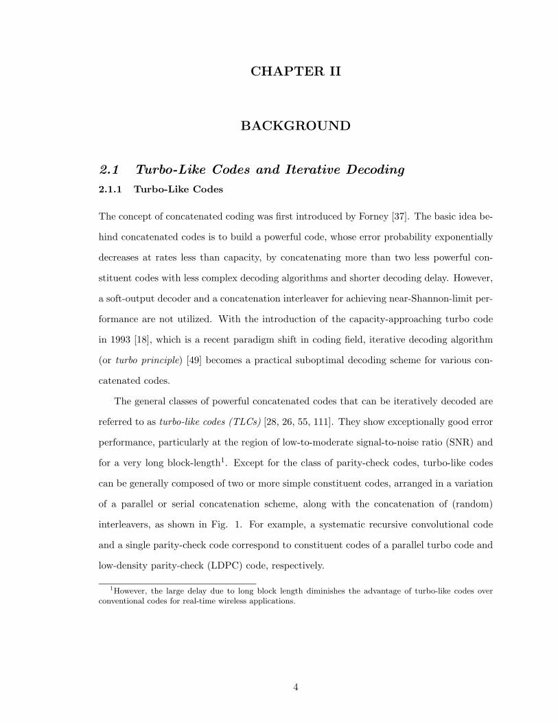
constituent codes taken alone. Mixed concatenated codes (MCCs) where the outer and/or
inner codes can be constructed by using multiple constituent codes are considered as a
family of turbo-like codes. Fig. 2 shows an example of the MCCs having multiple outer and
2In terms of codes on graphs, the time-axis of the trellis can be represented by an arbitrary bipartitefactor (or Tanner) graph [120].
3comprise M two-state trellis codes interconnected by interleavers.4The RA codes can achieve the Shannon limit log 2 = -1.592 dB as the code rate goes to zero on an
AWGN channel [55].
5
inner codes. The output bits from the constituent codes are demultiplexed according to a
mixture ratio and then passed to the next encoding stage. The design and finding of an
optimal mixture ratio of the MCCs can be aided by using a decoding convergence analysis,
since it helps us to know advantages and disadvantages of constituent codes.
code outer,1
Outer mixed encoder Inner mixed encoder
...
code outer,i
code inner,1
code inner,j
...
Figure 2: A mixed concatenated code. Π represents a concatenation interleaver.
2.1.2 Turbo-Like Coded Modulations
By replacing the inner recursive encoder in SCCC with a recursive modulator, iterative
decoding algorithm can be applied to coded modulation schemes, such as bit-interleaved
coded modulation (BICM) [79], serially concatenated differential phase-shift keying (SC-
DPSK) [96, 98], and serially concatenated continuous phase modulation (SC-CPM) [97].
In general, turbo-like coded modulations (TLCMs) are composed of two or more simple
constituent encoders and modulators, arranged in a variation of the concatenation scheme,
along with interleaver(s). The constituent outer encoders can be trellis or block encoders,
such as a repetition code, convolutional code, turbo code, single parity-check (SPC) code,
or LDPC code.
DPSK modulation has been used for non-coherent detection where an accurate carrier
phase is difficult to establish [118]. In particular, binary DPSK can be viewed as a rate-1
differential encoder with the generator polynomial of 1/(1+D) (or an accumulator) followed
by a memoryless mapper. This inner rate-1 recursive trellis encoder plays an important role
6
in SC-DPSK5 [96, 98], similar to the recursive inner code in an SCCC scheme, such that
it provides a coding gain without adding redundancy because the weight-1 input-sequence
generates an infinite weight outout-sequence6. The differentially encoded output yk ∈ {0, 1}
at epoch k is
yk = yk−1 ⊕ xk, (1)
where xk is the convolutionally encoded output and ⊕ denotes the binary sum. The carrier
phase θk ∈ {0, π} is calculated as
θk = θk−1 + πxk. (2)
Some important observations regarding the SC-DPSK are as follows: 1) the interleaving
gain is dependent only on the interleaver size and minimum free-distance of the outer code,
and is independent of the inner DPSK parameters for large interleaver size, and 2) codewords
with small output-weight dominate bit error rate (BER) at high SNR.
Another popular and important modulation scheme is CPM [4, 106], which is a spectrally
efficient constant envelope non-linear digital modulation scheme and has inherent trellis
coding features created by the phase continuity. The CPM signals not only offer a compact
spectral main lobe and rapidly decaying side lobes, but also make it possible to use low-cost
and power-efficient non-linear amplifiers.
Consider SC-CPM consisting of an outer convolutional code, a random interleaver, and
an inner CPM [45, 97]. The transmitted CPM signal provides phase memory, and can
be decomposed into a time-invariant continuous-phase encoder (CPE) and a memoryless
modulator (MM) [106]. Therefore, CPM can be also viewed as an inner recursive trellis
encoder and it is well suited for a turbo-like coded modulation scheme.
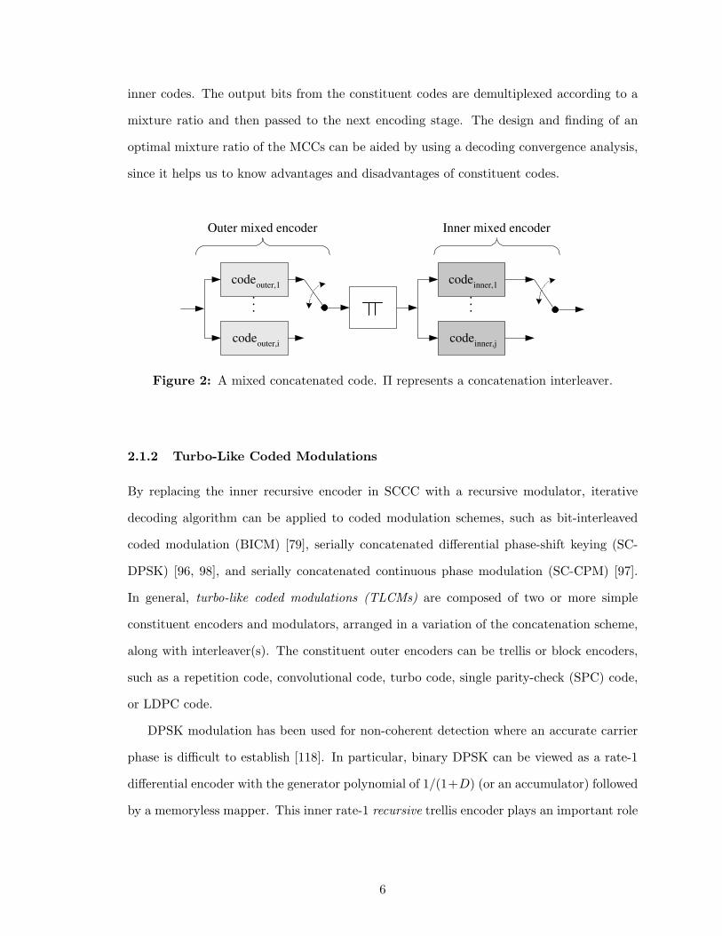
Minimum-shift keying (MSK) is the simplest and most popular binary CPM scheme
with a rectangular frequency shaping pulse. In particular, binary Gaussian MSK (GMSK)
has been widely used in GSM, Bluetooth, DECT, CDPD, and Mobitex. The MSK is decom-
posed into a rate-1/2 two-state recursive convolutional CPE with the generator polynomial
5Sometimes, it is called trellis-coded and interleaved DPSK.6However, the output weight is kept finite due to the trellis termination.
7
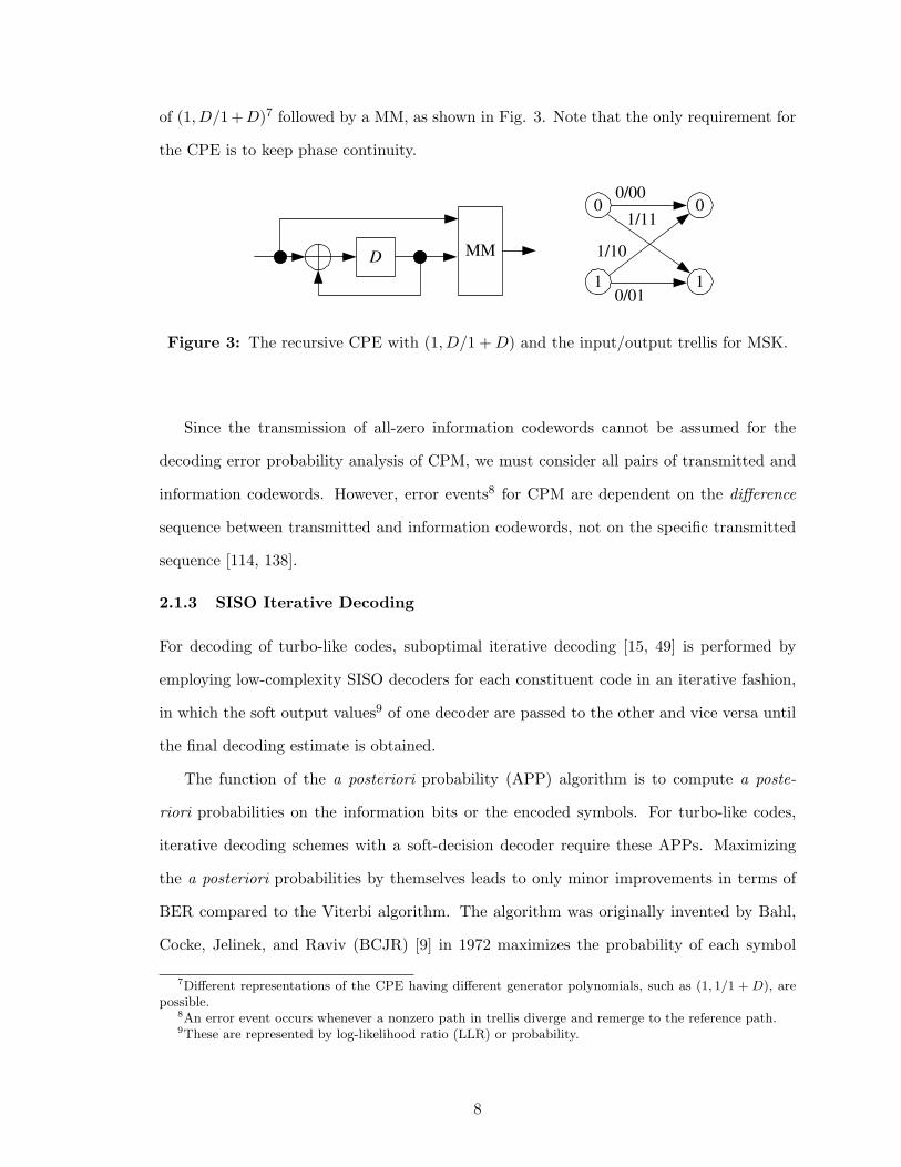
of (1, D/1+D)7 followed by a MM, as shown in Fig. 3. Note that the only requirement for
the CPE is to keep phase continuity.
D MM
0
1
0
1
0/00
1/11
1/10
0/01
Figure 3: The recursive CPE with (1, D/1 + D) and the input/output trellis for MSK.
Since the transmission of all-zero information codewords cannot be assumed for the
decoding error probability analysis of CPM, we must consider all pairs of transmitted and
information codewords. However, error events8 for CPM are dependent on the difference
sequence between transmitted and information codewords, not on the specific transmitted
sequence [114, 138].
2.1.3 SISO Iterative Decoding
For decoding of turbo-like codes, suboptimal iterative decoding [15, 49] is performed by
employing low-complexity SISO decoders for each constituent code in an iterative fashion,
in which the soft output values9 of one decoder are passed to the other and vice versa until
the final decoding estimate is obtained.
The function of the a posteriori probability (APP) algorithm is to compute a poste-
riori probabilities on the information bits or the encoded symbols. For turbo-like codes,
iterative decoding schemes with a soft-decision decoder require these APPs. Maximizing
the a posteriori probabilities by themselves leads to only minor improvements in terms of
BER compared to the Viterbi algorithm. The algorithm was originally invented by Bahl,
Cocke, Jelinek, and Raviv (BCJR) [9] in 1972 maximizes the probability of each symbol
7Different representations of the CPE having different generator polynomials, such as (1, 1/1 + D), arepossible.
8An error event occurs whenever a nonzero path in trellis diverge and remerge to the reference path.9These are represented by log-likelihood ratio (LLR) or probability.
8
being correct, and is referred to as the maximum a posteriori probability (MAP) algorithm.
The MAP algorithm was not widely used until the invention of the turbo code, since it
provided no significant improvement over the maximum-likelihood (ML) decoder that is
implemented by the Viterbi algorithm [126] in spite of its increase in complexity. Various
implementation of decoding algorithms have been proposed, such as the Log-MAP [15],
Max-Log-MAP [107], soft-output Viterbi algorithm (SOVA) [49], sliding-window MAP [12].
They have a trade-off relationship between performance and complexity.
Finally, one of the weak points of iterative decoding is the latency due to iterative
calculations. This also results in more power consumption at the receiver.
From the viewpoint of graphical codes [128], the MAP and the Viterbi algorithms are
special cases of generic sum-product and min-sum algorithms [69], respectively. Therefore,
the iterative decoding occurs when the graph has cycles and, thus, is suboptimal with
lower-complexity compared to cycle-free optimal cases.
2.2 Adaptive Turbo-Like Coding and Hybrid-ARQ
2.2.1 Adaptive Error Control Systems
The adaptive error control system (AECS)10 can adaptively change the modules in trans-
mitter to diversify retransmissions according to estimated or unknown channel information.
Examples of the useful channel information include the SNR, data rate, received power,
bit/frame errors, fading parameters (fade duration, Doppler frequency, and other channel
parameters), path loss, interference level, ARQ status messages, throughput, and round trip
delay. According to the estimated channel information, the AECS can adaptively change
code rates, packet size, forward error correction (FEC) code, modulation scheme, ARQ
protocol, and so on. In particular, since data needs different error protection and channel
is time-varying or unknown in many cases, adaptive error control coding (AECC) scheme is
an important design issue. Therefore, it is promising to design adaptive turbo-like coding
schemes by utilizing both the powerful error-correcting capability of turbo-like codes and
10In a nutshell, it includes adaptive coding, adaptive modulation [104], and adaptive antenna schemes.However, our primary concern is about the AECC system.
9
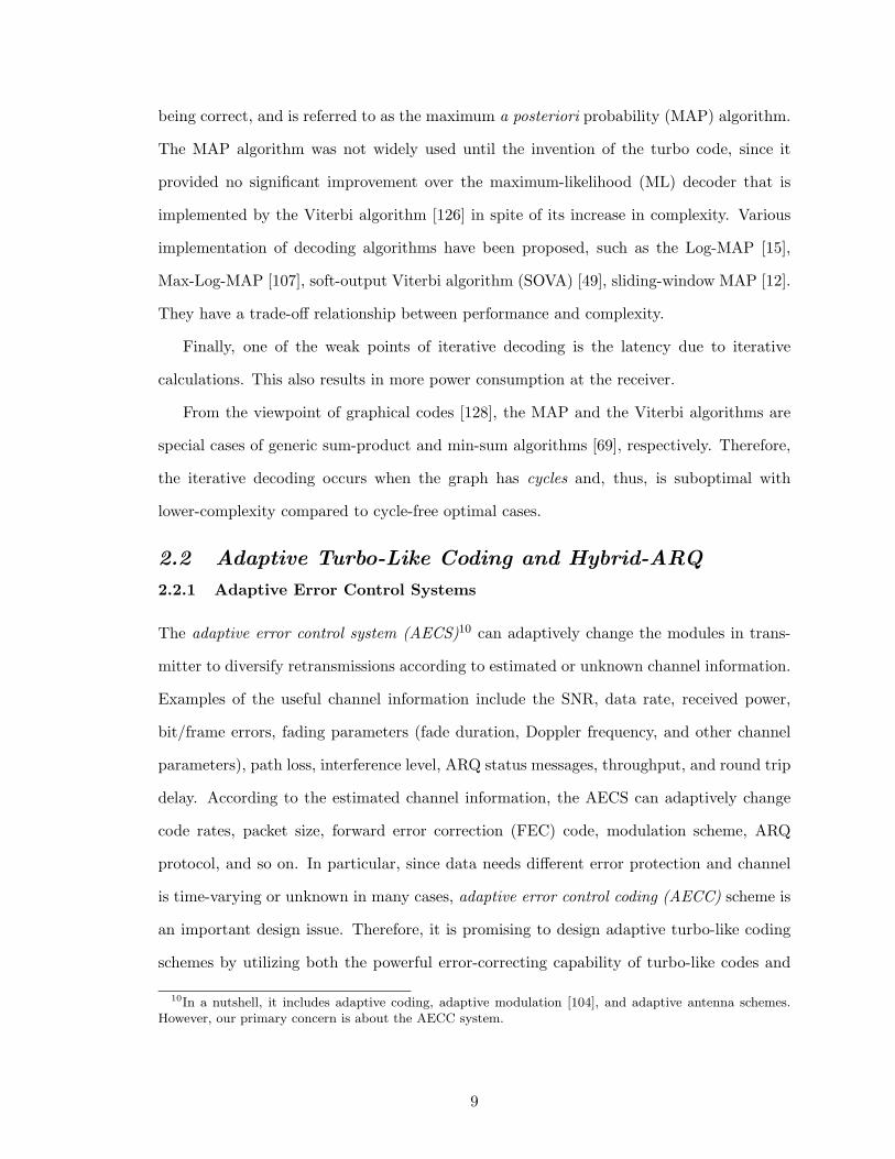
adaptability of the AECC scheme. The general structure of the AECC system is shown in
Fig. 4.
AEC
Encoder Forward Channel
AEC
Decoder
Feedback Channel
Channel
Estimator
ACK/NAK
Figure 4: General structure of the AECC system with a channel estimator. Forward andfeedback channels exist.
The change of modules (or their possible combinations) in the AECS system and their
examples for AECS systems are summarized in Table 1.
Table 1: Change of modules for the adaptive error control system.Change Example
Code rates 1/2 → 1/3
FEC coding schemes convolutional code → turbo code
HARQ schemes Type-II → Type-I (adaptive HARQ)
Puncturing patterns P(k) → P′(k)
Packet sizes (formats) 640 → 2 × 320 bits/packet
Transmit power 0.05 dB → 0.1 dB
Frequency subchannels subchannel assignment switching (multi-carrier)
Modulation QPSK → 16-QAM (adaptive modulation)
Interleaver switching of interleaver pattern
Antenna diversity antenna numbers (MIMO),switching of TX antenna and beam pattern
2.2.2 Hybrid-ARQ Schemes
There are two basic categories of error control schemes for data communications: FEC
schemes and ARQ schemes. Drawbacks of the ARQ and FEC schemes can be overcome if
they are properly incorporated. Such a combination of the two basic error control schemes
10
is referred to as hybrid-ARQ (HARQ)11 [80], [82]. The HARQ techniques have been exten-
sively used for packet data networks where retransmission is allowed. The main function of
the FEC system is to reduce the number of retransmissions by correcting the error patterns
that occur most frequently, usually at low SNR. This increases the system throughput per-
formance. However, when a less-frequent error pattern occurs and is detected, the receiver
requests a retransmission rather than passing the unreliably decoded message to the user.
This increases the system reliability. As a result, a proper combination of FEC and ARQ
provides higher reliability than an FEC system alone and higher throughput than a system
with ARQ alone.
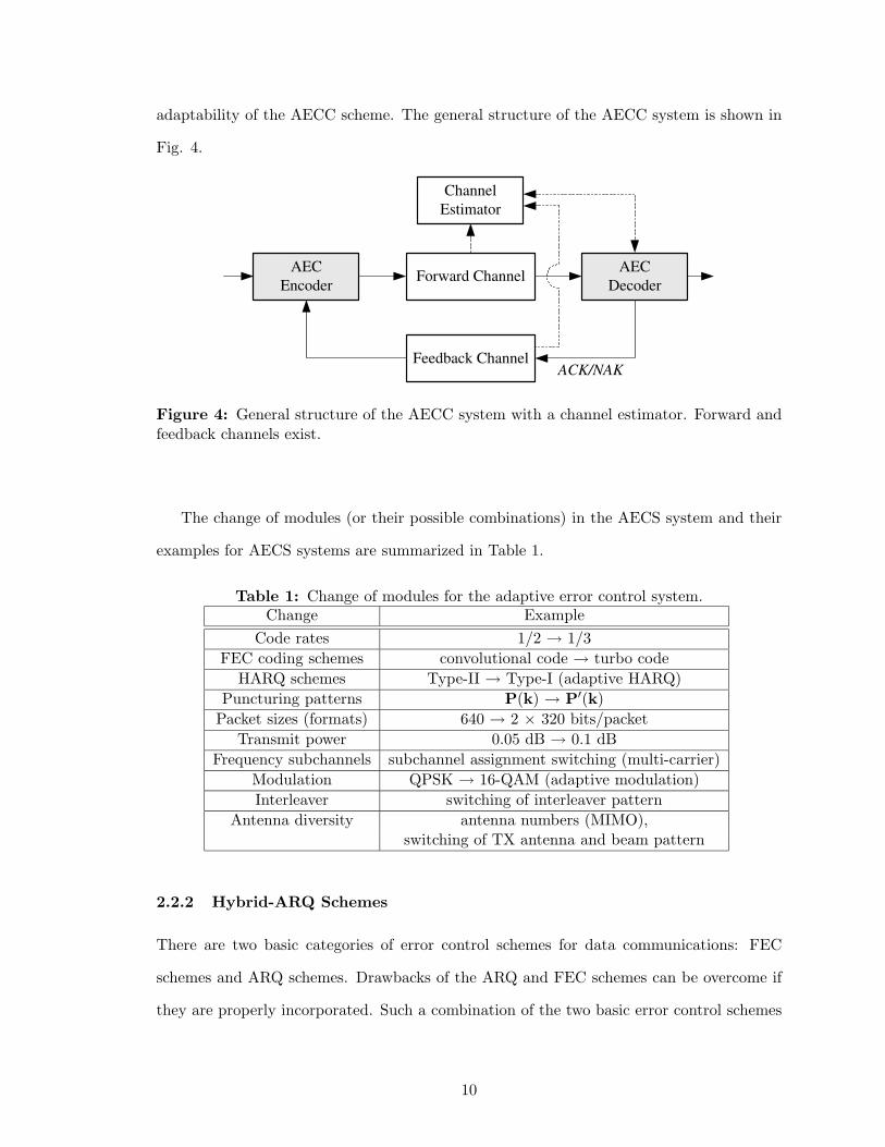
HARQ schemes can be classified into two categories: Type-I and Type-II HARQ schemes.
Briefly, the Type-I and Type-II HARQ schemes can be viewed as a full retransmission ARQ
and a partial retransmission ARQ strategies, respectively. Fig. 5 illustrates the examples
of the pure ARQ scheme and three types of HARQ schemes for comparison purpose.
P1
NAK
P2 P1 P2 P1 P2 NAK
P1 P2 P1 P2 NAK
NAK
NAK
NAK Pure ARQ:
Type-I HARQ:
Type-II HARQ:
1st trans. 2nd trans. 3rd trans.
C 1
C 2
C 3
C 1
C 2 , C
1 +C
2 C
3 , C
1 +C
2 +C
3
C 1
C 1 +C
2 C
1 +C
2 +C
3
Figure 5: Pure ARQ and hybrid-ARQ schemes. Three transmissions are shown. Ci
denotes a codeword for the i-th transmission, and P denotes the parity-check bits.
A straightforward Type-I HARQ scheme uses codes that are designed for error detection
and correction. When a received codeword is detected in error, the receiver first attempts to
correct the errors. If the number of errors is within the designed error correcting capability
of the code, the errors will be corrected and the decoded message will be delivered to the
user or saved in the buffer until it is ready to be passed to the user. It an uncorrectable error
11The hybrid-ARQ is sometimes called as the FEC/ARQ.
11
pattern is detected, the receiver rejects the received codeword and requests a retransmission.
The same codeword is retransmitted. When the retransmitted codeword is received, the
receiver again attempts to correct the errors (if any). If the decoding is not successful,
the receiver again rejects the received codeword and requests another retransmission. This
continues until the codeword is either successfully received or successfully decoded. Since a
code is used for both error correction and detection in a Type-I HARQ system, it requires
more parity-check bits than a code used only for error detection in a pure ARQ system.
As a result, the overhead for each transmission is increased. When the channel error rate
is low, a Type-I HARQ system has lower throughput than its corresponding ARQ system.
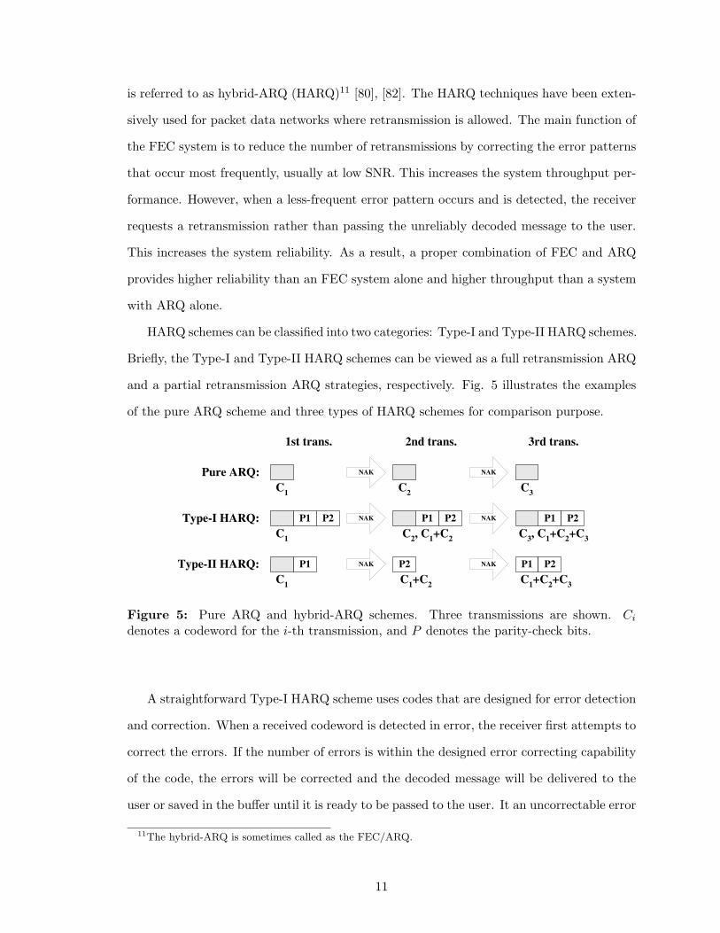
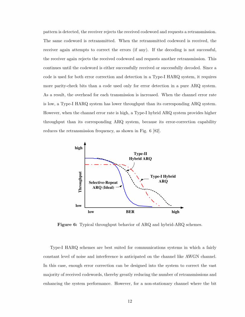
However, when the channel error rate is high, a Type-I hybrid ARQ system provides higher
throughput than its corresponding ARQ system, because its error-correction capability
reduces the retransmission frequency, as shown in Fig. 6 [82].
Th
rou
gh
pu
t
BER
Selective-Repeat
ARQ (Ideal)
Type-II
Hybrid ARQ
Type-I Hybrid
ARQ
high
low
low high
Figure 6: Typical throughput behavior of ARQ and hybrid-ARQ schemes.
Type-I HARQ schemes are best suited for communications systems in which a fairly
constant level of noise and interference is anticipated on the channel like AWGN channel.
In this case, enough error correction can be designed into the system to correct the vast
majority of received codewords, thereby greatly reducing the number of retransmissions and
enhancing the system performance. However, for a non-stationary channel where the bit
12
error rate changes, a Type-I HARQ scheme may have some drawbacks. When the BER
of channel is low, the transmission is smooth and no (or little) error correction is needed.
As a result, the extra parity-check bits for error correction included in each transmission
represent a waste. When the channel is very noisy, the designed error correcting capability
may become inadequate. As a result, the frequency of retransmission increases and hence
reduces the throughput. Several Type-I HARQ schemes using either block or convolutional
codes have been proposed and analyzed [136], [32]. For a channel with a non-stationary
error rate, one would like to design an adaptive HARQ system. When the channel is quiet,
the system behaves just like a pure ARQ system. However, when the channel becomes
noisy, extra bits are needed. This concept forms the basis of the Type-II HARQ schemes.
A message in its first transmission is coded with parity-check bits for error detection only.
When the receiver detects any error in a received codeword, it saves the erroneous codeword
in a buffer and at the same time requests a retransmission. The retransmission is not the
original codeword but a block of parity-check bits and an error correction code. When this
block of extra bits is received, it is used to correct the errors in the erroneous codeword
stored in the receiver buffer. The detailed algorithm depends on the retransmission strategy
and the type of error correcting code to be used. The concept of parity retransmission for
error correction and the first Type-II HARQ using a parity retransmission strategy were
first introduced by Mandelbaum [89] and by Metzner [92], respectively. Metzner’s scheme
was later extended and modified [82].
2.2.3 Rate Compatible Punctured Codes
Mandelbaum [89] was the first to propose punctured codes for transmitting redundancy
incrementally by using RS codes. However, Cain et al. [20] first introduced punctured con-
volutional codes (PCC) as a method for obtaining higher codes rates of 2/3 and 3/4 from a
rate 1/2 code, while using a same Viterbi decoder. Later, Hagenauer [48] proposed rate com-
patible punctured convolutional (RCPC) codes and Type-II RCPC-HARQ scheme. RCPC
codes are constructed by puncturing a single rate-1/n convolutional code rate-compatibly
to produce a family of higher rate codes. Erasures are inserted to mark the location of the
13
punctured bits at the decoder. The puncturing pattern should be generated such that the
rate compatible puncturing rules are satisfied. The rate compatible puncturing rule limits
the puncturing pattern such that all of the code symbols of a high rate punctured code must
be included in the lower rate codes (i.e., the higher rate codes should be used in the lower
rate codes). Instead of transmitting all the bits of a completely different low rate code,
the lower rate code must reuse the bits already transmitted. Therefore, only additional
incremental redundancy bits are transmitted.
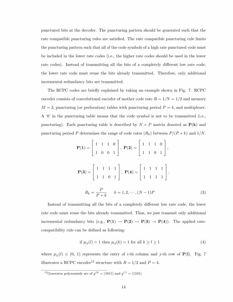
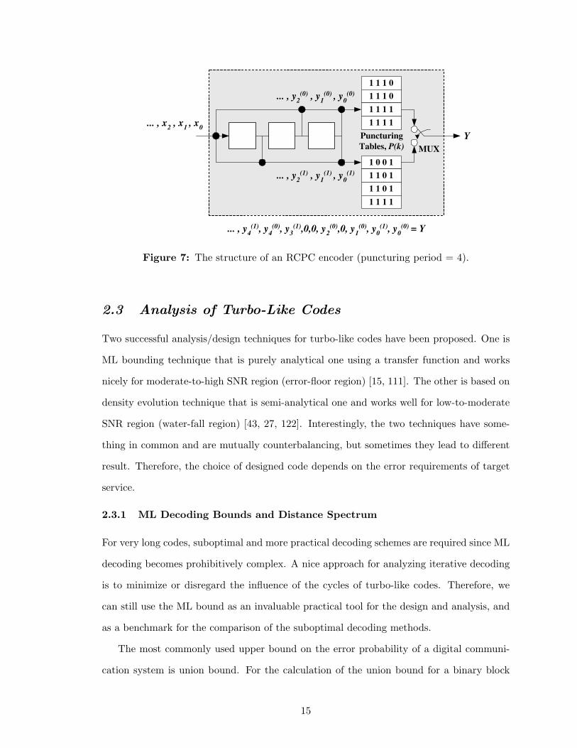
The RCPC codes are briefly explained by taking an example shown in Fig. 7. RCPC
encoder consists of convolutional encoder of mother code rate R = 1/N = 1/2 and memory
M = 3, puncturing (or perforation) tables with puncturing period P = 4, and multiplexer.
A ‘0’ in the puncturing table means that the code symbol is not to be transmitted (i.e.,
puncturing). Each puncturing table is described by N × P matrix denoted as P(k) and
puncturing period P determines the range of code rates (Rk) between P/(P + k) and 1/N .
P(1) =
1 1 1 0
1 0 0 1
, P(2) =
1 1 1 0
1 1 0 1
,
P(3) =
1 1 1 1
1 1 0 1
, P(4) =
1 1 1 1
1 1 1 1
.
Rk =P
P + kk = 1, 2, · · · , (N − 1)P (3)
Instead of transmitting all the bits of a completely different low rate code, the lower
rate code must reuse the bits already transmitted. Thus, we just transmit only additional
incremental redundancy bits (e.g., P(1) → P(2) → P(3) → P(4)). The applied rate-
compatibility rule can be defined as following:
if pij(l) = 1 then pij(k) = 1 for all k ≥ l ≥ 1 (4)
where pij(l) ∈ (0, 1) represents the entry of i-th column and j-th row of P(l). Fig. 7
illustrates a RCPC encoder12 structure with R = 1/2 and P = 4.
12Generator polynomials are of g(0) = (1011) and g(1) = (1101).
14
... , x 2 , x
1 , x
0
... , y 2
(0) , y 1
(0) , y
0 (0)
... , y 2
(1) , y 1
(1) , y
0 (1)
1 1 1 0
1 0 0 1
Puncturing
Tables, P(k)
... , y 4
(1) , y 4
(0) , y 3
(1) ,0,0, y 2 (0) ,0, y
1 (0) , y
0 (1) , y
0 (0) = Y
MUX
Y
1 1 0 1
1 1 1 0
1 1 0 1
1 1 1 1
1 1 1 1
1 1 1 1
Figure 7: The structure of an RCPC encoder (puncturing period = 4).
2.3 Analysis of Turbo-Like Codes
Two successful analysis/design techniques for turbo-like codes have been proposed. One is
ML bounding technique that is purely analytical one using a transfer function and works
nicely for moderate-to-high SNR region (error-floor region) [15, 111]. The other is based on
density evolution technique that is semi-analytical one and works well for low-to-moderate
SNR region (water-fall region) [43, 27, 122]. Interestingly, the two techniques have some-
thing in common and are mutually counterbalancing, but sometimes they lead to different
result. Therefore, the choice of designed code depends on the error requirements of target
service.
2.3.1 ML Decoding Bounds and Distance Spectrum
For very long codes, suboptimal and more practical decoding schemes are required since ML
decoding becomes prohibitively complex. A nice approach for analyzing iterative decoding
is to minimize or disregard the influence of the cycles of turbo-like codes. Therefore, we
can still use the ML bound as an invaluable practical tool for the design and analysis, and
as a benchmark for the comparison of the suboptimal decoding methods.
The most commonly used upper bound on the error probability of a digital communi-
cation system is union bound. For the calculation of the union bound for a binary block
15
code, one only needs to have the input-output weight enumerating function (or distance
spectrum) of the code. For turbo-like codes, the modified ensemble distance spectrum that
is calculated from a uniform interleaver assumption has been often used, because it is quite
difficult to evaluate the performance for a specific interleaver [13]. The probabilistic uniform
interleaving is devised to map a given input-sequence of length N and weight l into its(N
l
)
distinct permutations with equal probability of 1/(N
l
)
. The premise is that there exists at
least one interleaver, which performs better than the average.
However, the union bound diverges in the low SNR region and, in particular, it is useless
at rates above the channel cutoff-rate. Recently, several new geometrical bounds that esti-
mate the BER performance more accurately at SNRs smaller than the cutoff-rate threshold
have been proposed [33, 34, 127, 110]. Most geometrical bounds are essentially derived from
the general Gallager’s first bound (GFB) in 1963 [41, 25]. The GFB is particularly suited
for fixed (particular) codes rather than random codes. The tangential-sphere bound (TSB)
proposed by Herzberg and Poltyrev [103] is always tighter than the conventional union
bound and the Berlekamp’s tangential bound (TB) [16], especially for the low-to-moderate
SNR region. This is achieved by separating the radial and tangential components of the
Gaussian noise with a half-space as the underlying Gallager region. Recently, improved
bounds by Duman and Salehi [33, 34] and Sason and Shamai [110, 111, 112] have also been
proposed. The Duman-Salehi bound (DSB) based on the Gallager’s second bound (GSB)
technique in 1965 [42] requires a two-parameter optimization without integration. The DSB
is tight for a wide range of SNR where the union bound is already very loose.
The error probability is divided into joint probability of error and noise residing in
a Gallager region and joint probability of error and noise residing in the complement of
ℜ, where ℜ is a volume around the transmitted codeword. The choice of region ℜ is of
importance in the GFB-based bounding techniques. Different choices of the region result in
different bounds in different ranges of SNR. Therefore, the word error probability (WEP),
Pw(E), is
Pw(E) = P (E, r ∈ ℜ) + P (E, r /∈ ℜ) (5)
16

= P (E|r ∈ ℜ)P (r ∈ ℜ) + P (E|r /∈ ℜ)P (r /∈ ℜ), (6)
where r is the n-dimensional received vector. Having P (E|r /∈ ℜ) ≤ 1, Pw(E) is upper-
bounded by13
Pw(E) ≤ P (E, r ∈ ℜ) + P (r /∈ ℜ), (7)
The ML bounds for fading channels can be obtained with some modifications for the the
case of an AWGN channel. There have been efforts to derive bounds for fully interleaved
(independent) fading channels [51] and correlated (or partially interleaved) fading channels
[40, 60, 75].
The excellent performance of turbo-like codes using iterative decoding can also be at-
tributed to the spectrum thinning phenomena [99]. The multiplicity, which is the number of
codewords with the same Hamming weight, of the near neighbors is significantly decreased,
especially, at the region of low-to-moderate output-weights. The error performance of turbo-
like codes is governed by a whole region of low-weight distances, not only by the minimum
distance [110]. This is in contrast to ensembles of random codes [23] where typical weights
associated with typical sequences dominate. The weight spectra for RA codes and SC-
DPSK are closer to the binomial distribution of the random codes than those of component
codes and, thus, these codes provide excellent error performance.
The ensemble distance spectra of SCCCs and random codes are well matched for weights
larger than twice the Gilbert-Varshamov (GV) distance14, although the former is signifi-
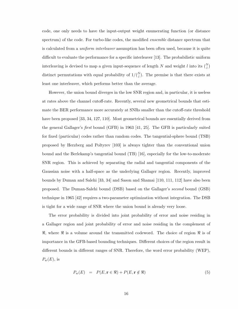
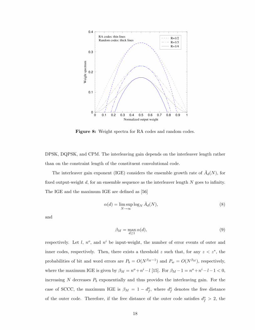
cantly larger than the latter for relatively low weights. As an example, Fig. 8 shows the
output-weight spectra for RA codes and random codes with different code rates. Notice
that RA codes have lower weights than random codes at the region of low output-weights.
The beneficial interleaving gain [15] of turbo-like codes, which means that a longer
block length always improve error performance, is possible only for a recursive15 inner
convolutional encoder such as differential encoders, and differential modulators such as
13In other words, instead of calculating the total error probability, the region of many errors is entirelytreated as erroneous and the region of few errors is only calculated.
14For normalized Hamming weight, the GV distance is 2H−12 (1−R), where H−1
2 (·) denotes the inverse ofbinary entropy function and R is code rate.
15For a recursive code, a single-weight input sequence does not cause an error event.
17
0 0.1 0.2 0.3 0.4 0.5 0.6 0.7 0.8 0.9 1
Normalized output weight
0
0.1
0.2
0.3
0.4
Wei
ght
spec
trum
R=1/2
R=1/3
R=1/4
RA codes: thin linesRandom codes: thick lines
Figure 8: Weight spectra for RA codes and random codes.
DPSK, DQPSK, and CPM. The interleaving gain depends on the interleaver length rather
than on the constraint length of the constituent convolutional code.
The interleaver gain exponent (IGE) considers the ensemble growth rate of Ad(N), for
fixed output-weight d, for an ensemble sequence as the interleaver length N goes to infinity.
The IGE and the maximum IGE are defined as [56]
α(d) = lim supN→∞
logN Ad(N), (8)
and
βM = maxd≥1
α(d), (9)
respectively. Let l, no, and ni be input-weight, the number of error events of outer and
inner codes, respectively. Then, there exists a threshold z such that, for any z < z∗, the
probabilities of bit and word errors are Pb = O(NβM−1) and Pw = O(NβM ), respectively,
where the maximum IGE is given by βM = no +ni− l [15]. For βM −1 = no +ni− l−1 < 0,
increasing N decreases Pb exponentially and thus provides the interleaving gain. For the
case of SCCC, the maximum IGE is βM = 1 − dof , where do
f denotes the free distance
of the outer code. Therefore, if the free distance of the outer code satisfies dof > 2, the
18
exponent of N is always negative. For a non-recursive inner code, βM = no − 1 ≥ 0 and an
interleaving gain is not obtained. However, for a recursive inner code, Pb decreases with N
as N−⌊(dof+1)/2⌋ and is mainly dependent on the minimum weight of the codewords for the
input sequences of weight-2 and -3.
2.3.2 Density Evolution and Convergence Analysis
For turbo-like codes, the traditional ML bounding techniques based on distance spectrum
usually do not exactly explain the error performance at low-to-moderate SNR region or the
water-fall region where the excellent performance is achieved [13]. However, the performance
of the iterative systems can be investigated by convergence analysis, as proposed in [43,
27, 122]. The iterative decoder can be viewed as a nonlinear dynamical feedback system.
The density of extrinsic information in iterative decoders can be tracked by actual density
evolution (DE) and by Gaussian density functions to analyze the performance of the turbo-
like codes [27, 26] and graphical codes [128]. By doing so, we can gain many insights into
the performance at the water-fall region and we can design more powerful turbo-like codes
by using the characteristics of constituent codes (e.g., recursiveness and state-complexity).
This asymptotic semi-analysis requires very long block lengths (i.e., N → ∞) and an infinite
number of iterations (i.e., m → ∞). The accurate analysis for short-to-moderate block
lengths (or finite interleaver lengths) remains unsolved. In this case, adjacent extrinsic
information will be correlated, thus causing performance degradation.
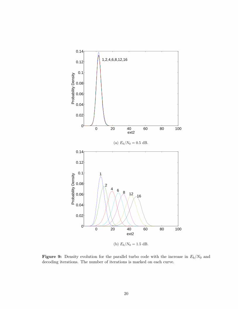
The density evolution method tracks the probability density function (pdf)16, p(λ), of
the input and output extrinsic information messages, λ, in the iterative decoders as the
iterations proceed, and computes the decoding threshold. In Fig. 9, the density evolution
phenomenon of the rate-1/3 parallel turbo code is simulated. In case of Eb/N0 = 1.5 dB,
the Gaussian-shaped density evolves with wider distribution and with both increasing mean
and variance as the iterations proceed.
The decoding threshold represents some Eb/N0 point where the two input-output ex-
trinsic information curves intersect. If the decoder operates an Eb/N0 greater than the
16The pdf can be calculated from the histogram of λ.
19
0 20 40 60 80 1000
0.02
0.04
0.06
0.08
0.1
0.12
0.14
ext2
Pro
babi
lity
Den
sity
1,2,4,6,8,12,16
(a) Eb/N0 = 0.5 dB.
0 20 40 60 80 1000
0.02
0.04
0.06
0.08
0.1
0.12
0.14
ext2
Pro
babi
lity
Den
sity 1
2 4 6 8 12 16
(b) Eb/N0 = 1.5 dB.
Figure 9: Density evolution for the parallel turbo code with the increase in Eb/N0 anddecoding iterations. The number of iterations is marked on each curve.
20
threshold, the iterative decoder converges and thus the BER goes to zero (Pb → 0) as the
iterations increase (m → ∞). The threshold is found to correspond to the sharp water-fall
region on BER curve.
Furthermore, the exchange of extrinsic information can be visualized as a decoding tra-
jectory in the extrinsic information transfer chart (EXIT chart) [121, 122]. This measure
is found to be more robust for clipping since no Gaussian assumption is imposed on the
extrinsic output distributions p(λ). However, for short-to-moderate block lengths, the aver-
aged trajectory dies out after some iterations (i.e., fail to reach the right-upper corner) due
to the increasing correlations of extrinsic information. If the mutual information is zero, the
extrinsic information has no information about transmitted codewords. On the contrary, if
it approaches one, the transmitted codewords are known and, thus, error-free decoding is
possible.
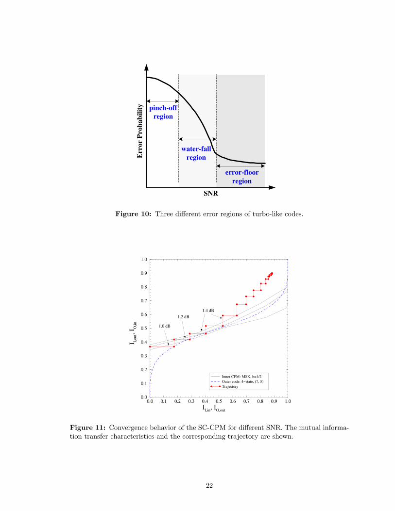
For a BER curve for turbo-like codes, three different regions can generally be classified as
depicted in Fig. 10. Firstly, the pinch-off region – the low SNR region where negligible BER
reduction through iterations is observed. The decoder transfer characteristics intersect at
the low value of mutual information (corresponding to high BER) and the trajectory gets
stuck. Secondly, the water-fall region – the bottleneck region where the trajectory just
manages to sneak through a narrow tunnel. Convergence is slow, but is possible, since both
curves do not intersect anymore. Finally, the error-floor region – the wide-open tunnel
region with fast convergence. The BER improvement is relatively small.
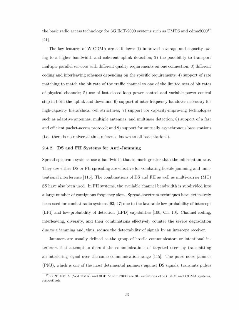
As an example, Fig. 11 shows the convergence behavior of the SC-CPM having in-
ner MSK and 4-state outer code for different Eb/N0. For Eb/N0 = 1.0 dB, the decoder
transfer characteristics inevitably intersect at around (II,in, II,out) = (0.25, 0.4) after some
iterations. The trajectory just sneaks through the curves in case of Eb/N0 = 1.2 dB.
2.4 Spread-Spectrum Communications
2.4.1 W-CDMA System
CDMA [74, 125] has successfully been adopted for IS-95 digital cellular systems [54] to pro-
vide high user-capacity and high data rate. Later, W-CDMA technology has been chosen as
21
Err
or
Pro
bab
ilit
y
SNR
pinch-off
region
water-fall
region
error-floor
region
Figure 10: Three different error regions of turbo-like codes.
0.0 0.1 0.2 0.3 0.4 0.5 0.6 0.7 0.8 0.9 1.0
II,in
, IO,out
0.0
0.1
0.2
0.3
0.4
0.5
0.6
0.7
0.8
0.9
1.0
I I,o
ut,
I O,i
n
Inner CPM: MSK, h=1/2
Outer code: 4−state, (7, 5)
Trajectory
1.0 dB
1.2 dB
1.4 dB
Figure 11: Convergence behavior of the SC-CPM for different SNR. The mutual informa-tion transfer characteristics and the corresponding trajectory are shown.
22
the basic radio access technology for 3G IMT-2000 systems such as UMTS and cdma200017
[21].
The key features of W-CDMA are as follows: 1) improved coverage and capacity ow-
ing to a higher bandwidth and coherent uplink detection; 2) the possibility to transport
multiple parallel services with different quality requirements on one connection; 3) different
coding and interleaving schemes depending on the specific requirements; 4) support of rate
matching to match the bit rate of the traffic channel to one of the limited sets of bit rates
of physical channels; 5) use of fast closed-loop power control and variable power control
step in both the uplink and downlink; 6) support of inter-frequency handover necessary for
high-capacity hierarchical cell structures; 7) support for capacity-improving technologies
such as adaptive antennas, multiple antennas, and multiuser detection; 8) support of a fast
and efficient packet-access protocol; and 9) support for mutually asynchronous base stations
(i.e., there is no universal time reference known to all base stations).
2.4.2 DS and FH Systems for Anti-Jamming
Spread-spectrum systems use a bandwidth that is much greater than the information rate.
They use either DS or FH spreading are effective for combating hostile jamming and unin-
tentional interference [115]. The combinations of DS and FH as well as multi-carrier (MC)
SS have also been used. In FH systems, the available channel bandwidth is subdivided into
a large number of contiguous frequency slots. Spread-spectrum techniques have extensively
been used for combat radio systems [93, 47] due to the favorable low-probability of intercept
(LPI) and low-probability of detection (LPD) capabilities [100, Ch. 10]. Channel coding,
interleaving, diversity, and their combinations effectively counter the severe degradation
due to a jamming and, thus, reduce the detectability of signals by an intercept receiver.
Jammers are usually defined as the group of hostile communicators or intentional in-
terferers that attempt to disrupt the communications of targeted users by transmitting
an interfering signal over the same communication range [115]. The pulse noise jammer
(PNJ), which is one of the most detrimental jammers against DS signals, transmits pulses
173GPP UMTS (W-CDMA) and 3GPP2 cdma2000 are 3G evolutions of 2G GSM and CDMA systems,respectively.
23
of band-limited white Gaussian noise having power Jpeak = J/ρ where J is the time-averaged
jamming power. The PNJ turns ON with enough power to degrade significantly the perfor-
mance of a target communication system. The jammer determines its pulse duty factor, ρ
(0 < ρ ≤ 1), which is a fraction of time during the jammer is ON, to maximize the system
degradation while keeping the constant average transmitted power J that is averaged over
total spread-spectrum bandwidth. The communicator must guarantee performance in worst
case jamming.
Jammer state information (JSI) yields the knowledge of jamming state (i.e., jammed
or unjammed) of the symbols where JSI is available at the receiver and it serves a variety
of purposes ranging from soft decoding metrics to jamming detection. The jammer state
random variable z is defined such that P (z = 1) = ρ if jammer is ON and P (z = 0) = 1− ρ
if jammer is OFF. The use of JSI is essential for coded spread-spectrum systems employing
soft-decision decoding, since a smart jammer can completely destroy the communications
links not utilizing JSI even with minimal jammer power [115].
Partial-band noise jamming (PBNJ) is one of the most effective jamming strategies
against FH systems. A PBNJ spreads noise of total power of J evenly over a frequency
range of bandwidth WJ , which is a subset of the full spread bandwidth Wss. The jammer
determines its duty factor, ρ△= WJ/Wss ∈ (0, 1], to maximize the system degradation.
During a FH dwell time of Th, let us define the jammer state random variable, z. A
hop is jammed with probability of P (z = 1) = ρ, and unjammed with probability of
P (z = 0) = 1 − ρ. It is usually assumed that the JSI yields the knowledge regarding the
jamming state of the modulated symbols.
24
CHAPTER III
DIRECT-SEQUENCE CONCATENATED CODED CPM
Spread-spectrum (SS) techniques using either DS or FH spreading with channel coding,
interleaving, diversity, and their combinations are effective for anti-jam and low probability-
of-intercept low probability-of-detection (LPI/LPD) communications [115]. CPM is a class
of constant envelope modulation schemes [4] having excellent spectral efficiency. Therefore,
coded DS-CPM signals promise good low LPI/LPD features.
Previous studies of uncoded DS multi-h CPM have demonstrated a 3-4 dB reduction
in detectability over conventional DS-BPSK modulation [72]. DS-MSK was also shown to
outperform DS-BPSK for an equivalent overall bandwidth [7]. Trellis-coded DS-CPM with
a non-iterative Viterbi receiver was proposed in [84]. A DS system employing coded and
interleaved CPM and Viterbi decoder was proposed in [137]. However, since the spreading
was performed after the CPM modulator, the phase continuity of CPM carrier was not
maintained.
In this chapter, we propose a DS concatenated coded CPM system, such that the carrier
phase continuity is maintained with DS spreading. Coherent detection of CPM signaling on
fading channels is possible by using joint data detection and estimation [83] or pilot symbol
aided modulation [53]. Our receiver uses coherent iterative demodulation and decoding as
described in [45], [97]. DS spreading effectively yields a very low rate repetition code with
a code rate equal to the processing gain. We show that chip-wise interleaving degrades
the BER performance with iterative demodulation and decoding due to the non-optimality
of the iterative decoder. To remedy this artifact, we use a block-wise random interleaver
[66]. Motivated by better BER performance due to improved iterative decoder convergence
characteristics at low-to-medium Eb/NJ , we propose a mixed concatenated coded system
consisting of a mixture of recursive and non-recursive CPM modulators with an optimized
mixture ratio. Such mixing can also improve LPI performance because an intercept receiver
25
must know the mixture ratio for correct detection. Finally, since jammer state information
(JSI) is crucial with soft-decision decoding [115], the soft-decision metrics in our iterative
receiver employ JSI.
The main contributions can be summarized as follows: i) phase-continuous DS con-
catenated coded CPM transmitter and an iterative receiver that incorporates JSI; ii) anti-
jamming performance of coded DS-CPM signaling with iterative demodulation/decoding is
investigated through simulation and union bound analysis; iii) code mixing for the enhance-
ment of BER performance by improving iterative decoder convergence.
3.1 System Model
3.1.1 Transmitter Structure
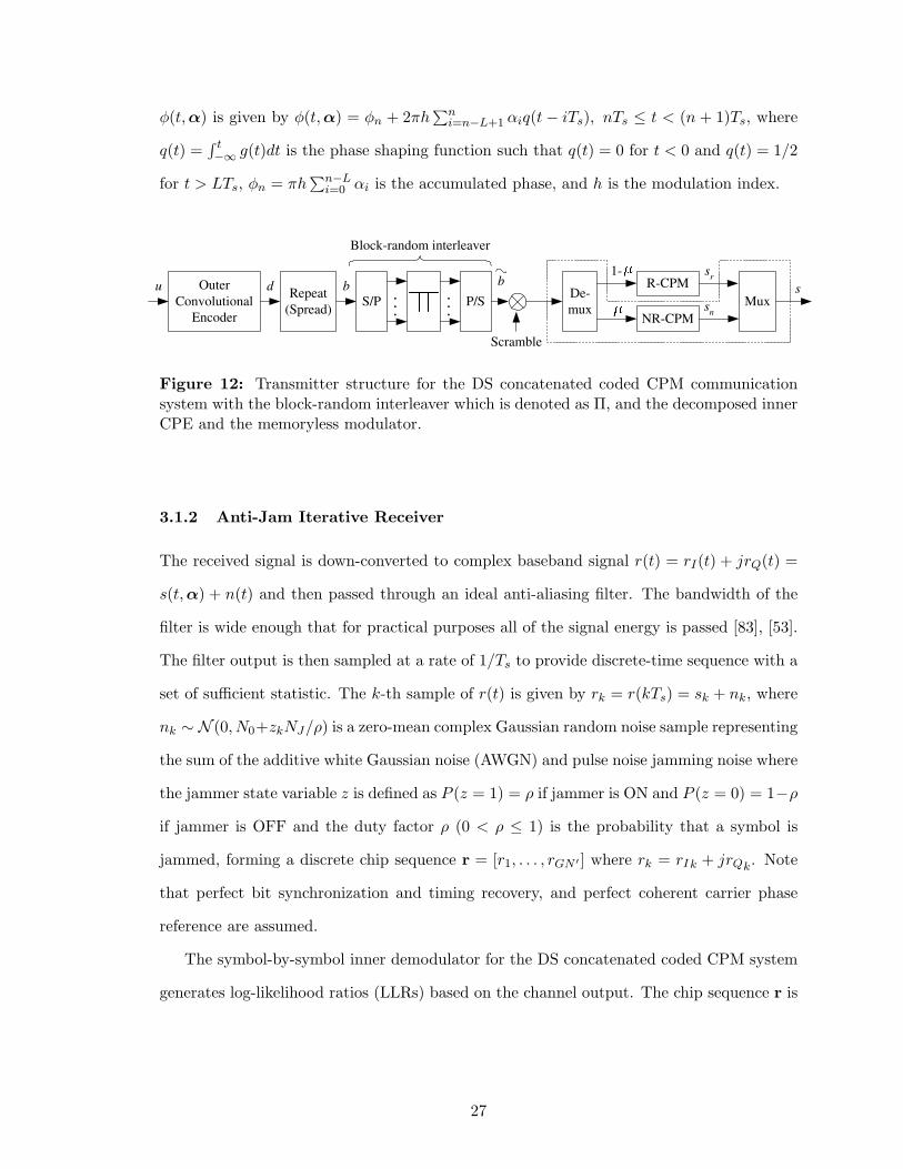
Fig. 12 shows the transmitter of the block-random interleaved concatenated coded DS-CPM
system. A length-N binary input sequence u is encoded by a rate-N/N ′ outer convolutional
encoder. The length-N ′ binary output sequence d from the outer encoder is multiplexed,
and each code bit is repeated G times to yield the sequence b, where G is the processing
gain. The sequence b is input to a buffer of size G × N ′, such that the G rows repeat
the length-N ′ sequence. Block-wise interleaving is performed, where the columns of the
G×N ′ matrix are randomly interleaved. Such block-wise random interleaving is used rather
than chip-wise random interleaving to overcome the BER degradation that will result from
non-maximum likelihood iterative decoding at a very low chip energy-to-noise ratios. The
interleaver output is converted into a length-GN ′ serial sequence b that is scrambled with
a user-specific binary PN sequence c. The binary sequence b is mapped onto the M -ary
symbol sequence α, α ∈ {±1,±3, . . . ,±(M − 1)}, which is input to the M -ary recursive
CPM modulator. Note that the dotted-line block is used in the case of the mixed recursive
(R) and non-recursive (NR) CPM modulator as will be described later. Let s(t, α) denote
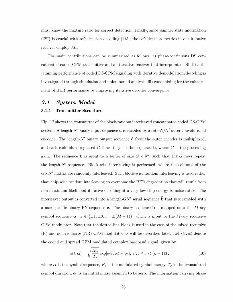
the coded and spread CPM modulated complex baseband signal, given by
s(t, α) =
√
2Es
Tsexp[φ(t, α) + φ0], nTs ≤ t < (n + 1)Ts (10)
where α is the symbol sequence, Es is the modulated symbol energy, Ts is the transmitted
symbol duration, φ0 is an initial phase assumed to be zero. The information carrying phase
26
φ(t, α) is given by φ(t, α) = φn + 2πh∑n
i=n−L+1 αiq(t − iTs), nTs ≤ t < (n + 1)Ts, where
q(t) =∫ t−∞ g(t)dt is the phase shaping function such that q(t) = 0 for t < 0 and q(t) = 1/2
for t > LTs, φn = πh∑n−L
i=0 αi is the accumulated phase, and h is the modulation index.
Outer
Convolutional
Encoder
u Repeat
(Spread)
d b
S/P P/S
...
...
b
Block-random interleaver
s r
R-CPM
NR-CPM s
n
De-
mux Mux
Scramble
s
1-
Figure 12: Transmitter structure for the DS concatenated coded CPM communicationsystem with the block-random interleaver which is denoted as Π, and the decomposed innerCPE and the memoryless modulator.
3.1.2 Anti-Jam Iterative Receiver
The received signal is down-converted to complex baseband signal r(t) = rI(t) + jrQ(t) =
s(t, α) + n(t) and then passed through an ideal anti-aliasing filter. The bandwidth of the
filter is wide enough that for practical purposes all of the signal energy is passed [83], [53].
The filter output is then sampled at a rate of 1/Ts to provide discrete-time sequence with a
set of sufficient statistic. The k-th sample of r(t) is given by rk = r(kTs) = sk + nk, where
nk ∼ N (0, N0+zkNJ/ρ) is a zero-mean complex Gaussian random noise sample representing
the sum of the additive white Gaussian noise (AWGN) and pulse noise jamming noise where
the jammer state variable z is defined as P (z = 1) = ρ if jammer is ON and P (z = 0) = 1−ρ
if jammer is OFF and the duty factor ρ (0 < ρ ≤ 1) is the probability that a symbol is
jammed, forming a discrete chip sequence r = [r1, . . . , rGN ′ ] where rk = rIk + jrQk. Note
that perfect bit synchronization and timing recovery, and perfect coherent carrier phase
reference are assumed.
The symbol-by-symbol inner demodulator for the DS concatenated coded CPM system
generates log-likelihood ratios (LLRs) based on the channel output. The chip sequence r is
27
descrambled and despread using the known PN sequence c as
yj =G∑
k=1
cj+(k−1)N ′ · rj+(k−1)N ′ , j = 1, . . . , N ′. (11)
Given the despread sequence y, the inner demodulator generates LLRs for each element
in the sequence d that represents the randomly interleaved code bit sequence of d. The
composite LLRs for the j-th code bit at the output of the demodulator are given by
Lmi (dj) = log
[
P (y|dj = 1, zj = z)
P (y|dj = 0, zj = z)
]
+ log
[
P (dj = 1)
P (dj = 0)
]
, (12)
where subscript i and superscript m denote the inner demodulator and the m-th iteration,
respectively, and the branch transition probability in the MAP decoder for channel use j
in the presence of pulse noise jamming is p(yj |dj , zj = z) = exp [−|yj − dj |2/2σ2z ]/√
2πσ2z ,
where yj , zj , dj , and σ2z represent the demodulator output, the jammer state, the channel
input, and noise variance, respectively. Then, (12) can be decomposed as
Lmi (dj) = Lm
i,e(dj) + Lmi,a(dj) = Lm
i,e(dj) + Lm−1o,e (dj), (13)
where the subscripts o, a, and e denote the outer decoder, the a priori information, and the
extrinsic information, respectively. The extrinsic LLRs Lmi,e(dj) in (13) are deinterleaved
and forwarded to the outer decoder. The a posteriori LLRs Lmo (dj) for the outer decoder
is calculated using the trellis structure and Lmi,e(dj) as Lm
o (dj) = Lmo,e(dj) + Lm
o,a(dj) =
Lmo,e(dj)+Lm
i,e(dj), m ≥ 1. Finally, only the bit extrinsic information Lmo,e(dj) is fed back to
the inner demodulator after interleaving as the a priori LLRs for dj , Lm−1o,e (dj), as shown
in (13).
3.1.3 Chip-by-Chip Random Interleaved System
In this section, the iterative receiver for the chip-wise random interleaved DS concatenated
coded CPM system is described for purposes of comparison with block-wise random inter-
leaving. In contrast to block-wise random interleaving, the spread sequence b is randomly
permuted chip-by-chip and then scrambled using the PN sequence c. Finally, the scrambled
sequence α is input to the CPM modulator. Note that the length of the random interleaver
is G ·N ′. In the presence of pulse jamming, the jammer will stay on for the entire duration
28
of a chip when jammed. At the receiver, the inner demodulator generates LLRs for each
bit in the sequence b given the received sequence r. The composite LLRs of the inner
demodulator at the j-th bit and k-th chip intervals can be calculated by replacing dj and y
in (12) with bj,k and r, respectively. The generated extrinsic LLRs Lmi,e(bj,k) that are used
as inputs to the outer decoder are descrambled and then deinterleaved chip-by-chip. Then
the deinterleaved extrinsic LLRs Lmi,e(bj,k) are combined such that constituent probabilities
are weighted according to the JSI, i.e.,
Lmi,e(bj) =
G∑
k=1
Lmi,e(bj,k)
=G∑
k=1
log
[
∑
m
∑
m′ αj−1(m′)βj(m)γ1(rj,k, zj,k, m
′, m)∑
m
∑
m′ αj−1(m′)βj(m)γ0(rj,k, zj,k, m′, m)
]
, (14)
where sj = m and sj−1 = m′ represent the trellis state transition, αj(m) and βj(m)
represent the forward and backward recursion probability functions, respectively, and the
branch transition probability is γi(rj,k, zj,k, m′, m) = p(rj,k|bj,k = i, zj,k = z, sj−1 = m′, sj =
m)p(zj,k = z)P (sj = m|bj,k = i, sj−1 = m′). The combined LLRs in (14) are forwarded
to the outer decoder, and the a posteriori LLRs Lmo (bj) from the outer decoder can be
calculated in a similar way. To pass the chip extrinsic LLRs to the inner demodulator, the
extrinsic LLRs are spread and then scrambled.
3.2 Bound Analysis of the Anti-Jamming Performance
The upper bound on BER for the block-wise random interleaved DS concatenated coded
CPM system is calculated by applying the serially concatenated code approach based on the
ensemble uniform interleaver in [13]. We briefly describe this modification by considering a
system with overall rate R = m/p, wherein the outer convolutional code with rate Ro = m/n
and the inner CPM with rate Ri = n/p = 1 are joined by an interleaver of length N ′. The
pairwise error probability Ppw(d) in the presence of pulse noise jamming is calculated by
conditioning on the event that k of d CPM symbols are jammed. Therefore, we can obtain
a closed-form upper bound on the bit error probability assuming ML soft-decision decoder
29
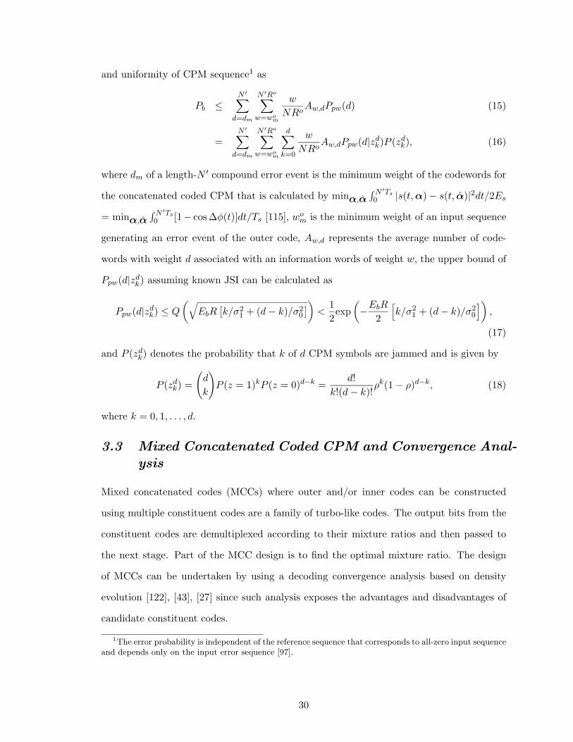
and uniformity of CPM sequence1 as
Pb ≤N ′
∑
d=dm
N ′Ro∑
w=wom
w
NRoAw,dPpw(d) (15)
=N ′
∑
d=dm
N ′Ro∑
w=wom
d∑
k=0
w
NRoAw,dPpw(d|zd
k)P (zdk), (16)
where dm of a length-N ′ compound error event is the minimum weight of the codewords for
the concatenated coded CPM that is calculated by minα,α
∫N ′Ts0 |s(t, α) − s(t, α)|2dt/2Es
= minα,α
∫N ′Ts0 [1− cos ∆φ(t)]dt/Ts [115], wo
m is the minimum weight of an input sequence
generating an error event of the outer code, Aw,d represents the average number of code-
words with weight d associated with an information words of weight w, the upper bound of
Ppw(d|zdk) assuming known JSI can be calculated as
Ppw(d|zdk) ≤ Q
(
√
EbR[
k/σ21 + (d − k)/σ2
0
]
)
<1
2exp
(
−EbR
2
[
k/σ21 + (d − k)/σ2
0
]
)
,
(17)
and P (zdk) denotes the probability that k of d CPM symbols are jammed and is given by
P (zdk) =
(
d
k
)
P (z = 1)kP (z = 0)d−k =d!
k!(d − k)!ρk(1 − ρ)d−k, (18)
where k = 0, 1, . . . , d.
3.3 Mixed Concatenated Coded CPM and Convergence Anal-
ysis
Mixed concatenated codes (MCCs) where outer and/or inner codes can be constructed
using multiple constituent codes are a family of turbo-like codes. The output bits from the
constituent codes are demultiplexed according to their mixture ratios and then passed to
the next stage. Part of the MCC design is to find the optimal mixture ratio. The design
of MCCs can be undertaken by using a decoding convergence analysis based on density
evolution [122], [43], [27] since such analysis exposes the advantages and disadvantages of
candidate constituent codes.
1The error probability is independent of the reference sequence that corresponds to all-zero input sequenceand depends only on the input error sequence [97].
30
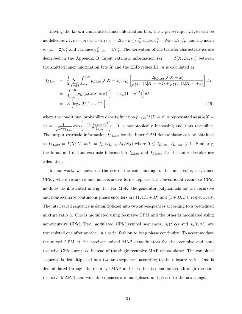
Having the known transmitted inner information bits, the a priori input L1, in can be
modelled as L1, in = νL1,in ·x+nL1,in = 2(x+nJ)/σ2z where σ2
z = N0+zNJ/ρ, and the mean
νL1,in = 2/σ2z and variance σ2
L1,in = 4/σ2z . The derivation of the transfer characteristics are
described in the Appendix B. Input extrinsic information IL1,in = I(X; L1, in) between
transmitted inner information bits X and the LLR-values L1, in is calculated as
IL1,in =1
2
∑
x=±1
∫ +∞
−∞pL1,in(λ|X = x) log2
[
2pL1,in(λ|X = x)
pL1,in(λ|X = −1) + pL1,in(λ|X = +1)
]
dλ
=
∫ +∞
−∞pL1,in(λ|X = x)
[
1 − log2(1 + e−λ)]
dλ
= E[
log2(2/(1 + e−λ)]
, (19)
where the conditional probability density function pL1,in(λ|X = x) is represented as p(λ|X =
x) = 1√
2πσ2L1,in
exp
{
− (λ−νL1,in·x)2
2σ2L1,in
}
. It is monotonically increasing and thus reversible.
The output extrinsic information IL1,out for the inner CPM demodulator can be obtained
as IL1,out = I(X; L1, out) = fL1(IL1,in, Eb/NJ) where 0 ≤ IL1,in, IL1,out ≤ 1. Similarly,
the input and output extrinsic information IL2,in and IL1,out for the outer decoder are
calculated.
In our work, we focus on the use of the code mixing to the inner code, i.e., inner
CPM, where recursive and non-recursive forms replace the conventional recursive CPM
modules, as illustrated in Fig. 13. For MSK, the generator polynomials for the recursive
and non-recursive continuous phase encoders are (1, 1/1 + D) and (1 + D, D), respectively.
The interleaved sequence is demultiplexed into two sub-sequences according to a predefined
mixture ratio µ. One is modulated using recursive CPM and the other is modulated using
non-recursive CPM. Two modulated CPM symbol sequences, sr(t, α) and sn(t, α), are
transmitted one after another in a serial fashion to keep phase continuity. To accommodate
the mixed CPM at the receiver, mixed MAP demodulators for the recursive and non-
recursive CPMs are used instead of the single recursive MAP demodulator. The combined
sequence is demultiplexed into two sub-sequences according to the mixture ratio. One is
demodulated through the recursive MAP and the other is demodulated through the non-
recursive MAP. Then two sub-sequences are multiplexed and passed to the next stage.
31
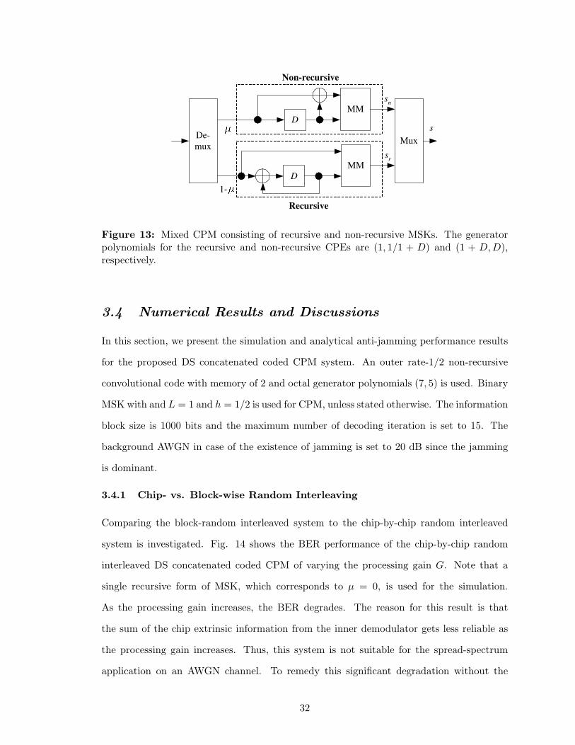
s n
s r
s De-
mux
D
MM
D
MM
Non-recursive
Recursive
Mux
1-
Figure 13: Mixed CPM consisting of recursive and non-recursive MSKs. The generatorpolynomials for the recursive and non-recursive CPEs are (1, 1/1 + D) and (1 + D, D),respectively.
3.4 Numerical Results and Discussions
In this section, we present the simulation and analytical anti-jamming performance results
for the proposed DS concatenated coded CPM system. An outer rate-1/2 non-recursive
convolutional code with memory of 2 and octal generator polynomials (7, 5) is used. Binary
MSK with and L = 1 and h = 1/2 is used for CPM, unless stated otherwise. The information
block size is 1000 bits and the maximum number of decoding iteration is set to 15. The
background AWGN in case of the existence of jamming is set to 20 dB since the jamming
is dominant.
3.4.1 Chip- vs. Block-wise Random Interleaving
Comparing the block-random interleaved system to the chip-by-chip random interleaved
system is investigated. Fig. 14 shows the BER performance of the chip-by-chip random
interleaved DS concatenated coded CPM of varying the processing gain G. Note that a
single recursive form of MSK, which corresponds to µ = 0, is used for the simulation.
As the processing gain increases, the BER degrades. The reason for this result is that
the sum of the chip extrinsic information from the inner demodulator gets less reliable as
the processing gain increases. Thus, this system is not suitable for the spread-spectrum
application on an AWGN channel. To remedy this significant degradation without the
32
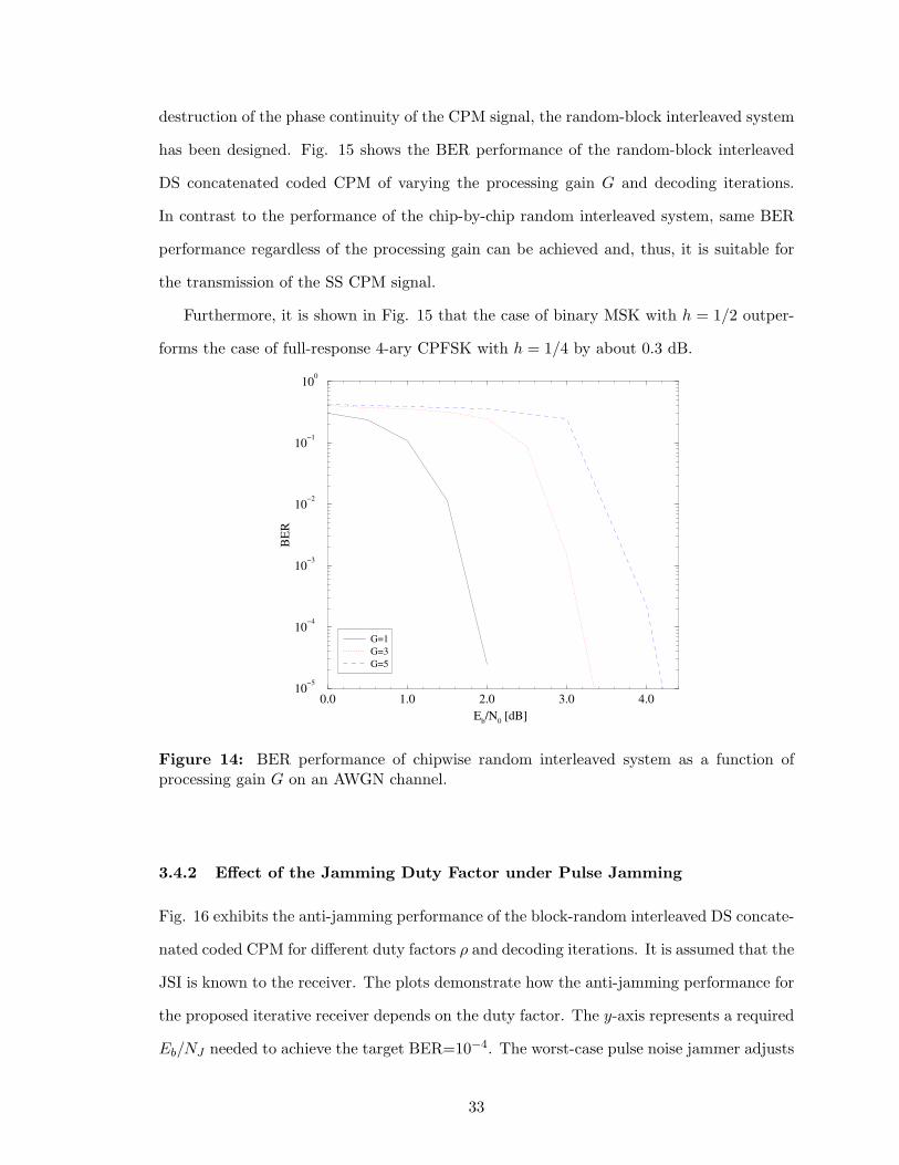
destruction of the phase continuity of the CPM signal, the random-block interleaved system
has been designed. Fig. 15 shows the BER performance of the random-block interleaved
DS concatenated coded CPM of varying the processing gain G and decoding iterations.
In contrast to the performance of the chip-by-chip random interleaved system, same BER
performance regardless of the processing gain can be achieved and, thus, it is suitable for
the transmission of the SS CPM signal.
Furthermore, it is shown in Fig. 15 that the case of binary MSK with h = 1/2 outper-
forms the case of full-response 4-ary CPFSK with h = 1/4 by about 0.3 dB.
0.0 1.0 2.0 3.0 4.0
Eb/N
0 [dB]
10−5
10−4
10−3
10−2
10−1
100
BE
R
G=1
G=3
G=5
Figure 14: BER performance of chipwise random interleaved system as a function ofprocessing gain G on an AWGN channel.
3.4.2 Effect of the Jamming Duty Factor under Pulse Jamming
Fig. 16 exhibits the anti-jamming performance of the block-random interleaved DS concate-
nated coded CPM for different duty factors ρ and decoding iterations. It is assumed that the
JSI is known to the receiver. The plots demonstrate how the anti-jamming performance for
the proposed iterative receiver depends on the duty factor. The y-axis represents a required
Eb/NJ needed to achieve the target BER=10−4. The worst-case pulse noise jammer adjusts
33
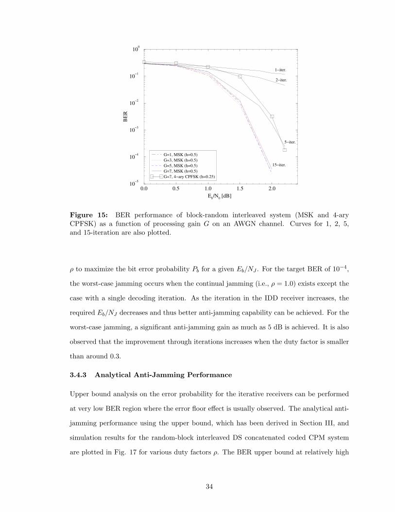
0.0 0.5 1.0 1.5 2.0
Eb/N
0 [dB]
10−5
10−4
10−3
10−2
10−1
100
BE
R
G=1, MSK (h=0.5)
G=3, MSK (h=0.5)
G=5, MSK (h=0.5)
G=7, MSK (h=0.5)
G=7, 4−ary CPFSK (h=0.25)
1−iter.
2−iter.
5−iter.
15−iter.
Figure 15: BER performance of block-random interleaved system (MSK and 4-aryCPFSK) as a function of processing gain G on an AWGN channel. Curves for 1, 2, 5,and 15-iteration are also plotted.
ρ to maximize the bit error probability Pb for a given Eb/NJ . For the target BER of 10−4,
the worst-case jamming occurs when the continual jamming (i.e., ρ = 1.0) exists except the
case with a single decoding iteration. As the iteration in the IDD receiver increases, the
required Eb/NJ decreases and thus better anti-jamming capability can be achieved. For the
worst-case jamming, a significant anti-jamming gain as much as 5 dB is achieved. It is also
observed that the improvement through iterations increases when the duty factor is smaller
than around 0.3.
3.4.3 Analytical Anti-Jamming Performance
Upper bound analysis on the error probability for the iterative receivers can be performed
at very low BER region where the error floor effect is usually observed. The analytical anti-
jamming performance using the upper bound, which has been derived in Section III, and
simulation results for the random-block interleaved DS concatenated coded CPM system
are plotted in Fig. 17 for various duty factors ρ. The BER upper bound at relatively high
34
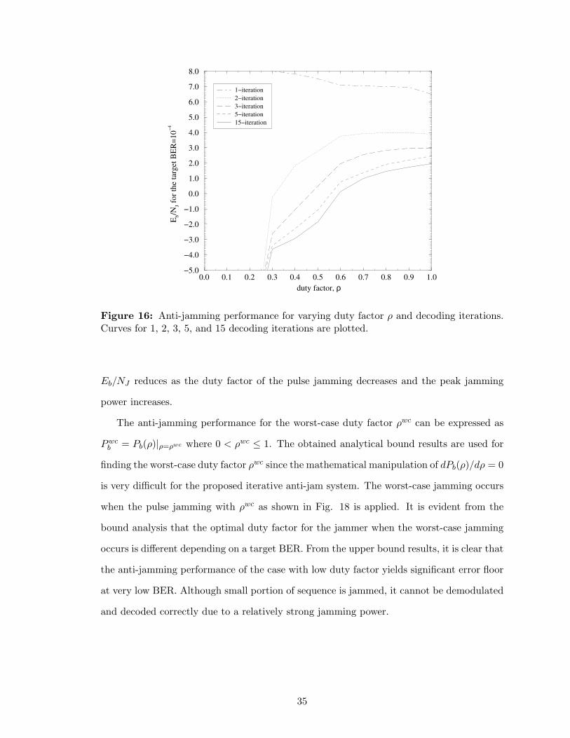
0.0 0.1 0.2 0.3 0.4 0.5 0.6 0.7 0.8 0.9 1.0
duty factor, ρ
−5.0
−4.0
−3.0
−2.0
−1.0
0.0
1.0
2.0
3.0
4.0
5.0
6.0
7.0
8.0
Eb/N
J fo
r th
e ta
rget
BE
R=
10
−4
1−iteration
2−iteration
3−iteration
5−iteration
15−iteration
Figure 16: Anti-jamming performance for varying duty factor ρ and decoding iterations.Curves for 1, 2, 3, 5, and 15 decoding iterations are plotted.
Eb/NJ reduces as the duty factor of the pulse jamming decreases and the peak jamming
power increases.
The anti-jamming performance for the worst-case duty factor ρwc can be expressed as
Pwcb = Pb(ρ)|ρ=ρwc where 0 < ρwc ≤ 1. The obtained analytical bound results are used for
finding the worst-case duty factor ρwc since the mathematical manipulation of dPb(ρ)/dρ = 0
is very difficult for the proposed iterative anti-jam system. The worst-case jamming occurs
when the pulse jamming with ρwc as shown in Fig. 18 is applied. It is evident from the
bound analysis that the optimal duty factor for the jammer when the worst-case jamming
occurs is different depending on a target BER. From the upper bound results, it is clear that
the anti-jamming performance of the case with low duty factor yields significant error floor
at very low BER. Although small portion of sequence is jammed, it cannot be demodulated
and decoded correctly due to a relatively strong jamming power.
35
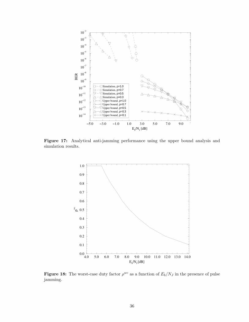
−5.0 −3.0 −1.0 1.0 3.0 5.0 7.0 9.0
Eb/N
J [dB]
10−14
10−13
10−12
10−11
10−10
10−9
10−8
10−7
10−6
10−5
10−4
10−3
10−2
BE
R
Simulation, ρ=1.0Simulation, ρ=0.7Simulation, ρ=0.5Simulation, ρ=0.3Upper bound, ρ=1.0Upper bound, ρ=0.7Upper bound, ρ=0.5Upper bound, ρ=0.3Upper bound, ρ=0.1
Figure 17: Analytical anti-jamming performance using the upper bound analysis andsimulation results.
4.0 5.0 6.0 7.0 8.0 9.0 10.0 11.0 12.0 13.0 14.0
Eb/N
J [dB]
0.0
0.1
0.2
0.3
0.4
0.5
0.6
0.7
0.8
0.9
1.0
ρwc
Figure 18: The worst-case duty factor ρwc as a function of Eb/NJ in the presence of pulsejamming.
36
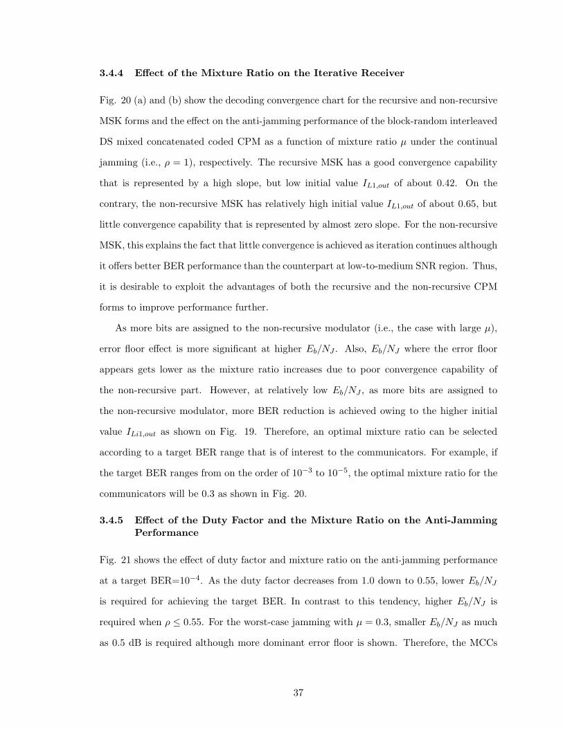
3.4.4 Effect of the Mixture Ratio on the Iterative Receiver
Fig. 20 (a) and (b) show the decoding convergence chart for the recursive and non-recursive
MSK forms and the effect on the anti-jamming performance of the block-random interleaved
DS mixed concatenated coded CPM as a function of mixture ratio µ under the continual
jamming (i.e., ρ = 1), respectively. The recursive MSK has a good convergence capability
that is represented by a high slope, but low initial value IL1,out of about 0.42. On the
contrary, the non-recursive MSK has relatively high initial value IL1,out of about 0.65, but
little convergence capability that is represented by almost zero slope. For the non-recursive
MSK, this explains the fact that little convergence is achieved as iteration continues although
it offers better BER performance than the counterpart at low-to-medium SNR region. Thus,
it is desirable to exploit the advantages of both the recursive and the non-recursive CPM
forms to improve performance further.
As more bits are assigned to the non-recursive modulator (i.e., the case with large µ),
error floor effect is more significant at higher Eb/NJ . Also, Eb/NJ where the error floor
appears gets lower as the mixture ratio increases due to poor convergence capability of
the non-recursive part. However, at relatively low Eb/NJ , as more bits are assigned to
the non-recursive modulator, more BER reduction is achieved owing to the higher initial
value ILi1,out as shown on Fig. 19. Therefore, an optimal mixture ratio can be selected
according to a target BER range that is of interest to the communicators. For example, if
the target BER ranges from on the order of 10−3 to 10−5, the optimal mixture ratio for the
communicators will be 0.3 as shown in Fig. 20.
3.4.5 Effect of the Duty Factor and the Mixture Ratio on the Anti-Jamming
Performance
Fig. 21 shows the effect of duty factor and mixture ratio on the anti-jamming performance
at a target BER=10−4. As the duty factor decreases from 1.0 down to 0.55, lower Eb/NJ
is required for achieving the target BER. In contrast to this tendency, higher Eb/NJ is
required when ρ ≤ 0.55. For the worst-case jamming with µ = 0.3, smaller Eb/NJ as much
as 0.5 dB is required although more dominant error floor is shown. Therefore, the MCCs
37

0.0 0.1 0.2 0.3 0.4 0.5 0.6 0.7 0.8 0.9 1.0
IL1,in
0.0
0.1
0.2
0.3
0.4
0.5
0.6
0.7
0.8
0.9
1.0
I L1
,ou
t
Non−recursive
Recursive
Figure 19: Convergence chart for MSK at Eb/NJ = 2 dB.
0.0 0.5 1.0 1.5 2.0 2.5
Eb/N
J [dB]
10−7
10−6
10−5
10−4
10−3
10−2
10−1
100
BE
R
µ=0.0µ=0.1µ=0.2µ=0.3µ=0.4µ=0.5µ=0.6µ=0.7µ=1.0
Figure 20: BER performance as a function of the mixture ratio µ under continual jamming.Note that µ = 0.0 and µ = 1.0 mean the recursive and non-recursive MSKs, respectively.
38
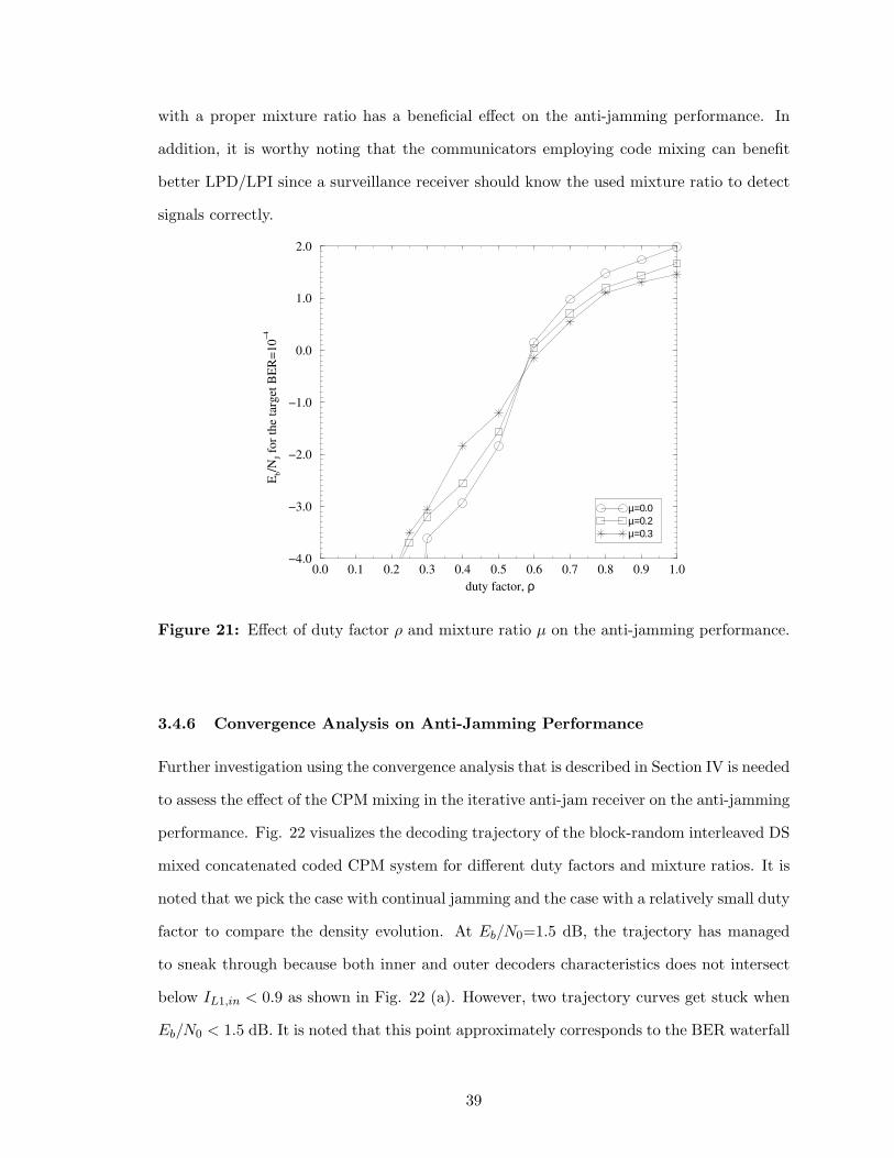
with a proper mixture ratio has a beneficial effect on the anti-jamming performance. In
addition, it is worthy noting that the communicators employing code mixing can benefit
better LPD/LPI since a surveillance receiver should know the used mixture ratio to detect
signals correctly.
0.0 0.1 0.2 0.3 0.4 0.5 0.6 0.7 0.8 0.9 1.0
duty factor, ρ
−4.0
−3.0
−2.0
−1.0
0.0
1.0
2.0
Eb/N
J fo
r th
e ta
rget
BE
R=
10
−4
µ=0.0µ=0.2µ=0.3
Figure 21: Effect of duty factor ρ and mixture ratio µ on the anti-jamming performance.
3.4.6 Convergence Analysis on Anti-Jamming Performance
Further investigation using the convergence analysis that is described in Section IV is needed
to assess the effect of the CPM mixing in the iterative anti-jam receiver on the anti-jamming
performance. Fig. 22 visualizes the decoding trajectory of the block-random interleaved DS
mixed concatenated coded CPM system for different duty factors and mixture ratios. It is
noted that we pick the case with continual jamming and the case with a relatively small duty
factor to compare the density evolution. At Eb/N0=1.5 dB, the trajectory has managed
to sneak through because both inner and outer decoders characteristics does not intersect
below IL1,in < 0.9 as shown in Fig. 22 (a). However, two trajectory curves get stuck when
Eb/N0 < 1.5 dB. It is noted that this point approximately corresponds to the BER waterfall
39
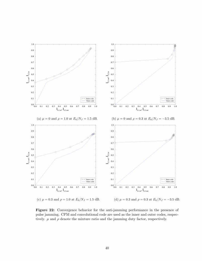
0.0 0.1 0.2 0.3 0.4 0.5 0.6 0.7 0.8 0.9 1.0
IL1,in
, IL2,out
0.0
0.1
0.2
0.3
0.4
0.5
0.6
0.7
0.8
0.9
1.0
I L1,o
ut,
I L2,i
n
Inner code
Outer code
0.0 0.1 0.2 0.3 0.4 0.5 0.6 0.7 0.8 0.9 1.0
IL1,in
, IL2,out
0.0
0.1
0.2
0.3
0.4
0.5
0.6
0.7
0.8
0.9
1.0
I L1,o
ut,
I L2,i
n
Inner code
Outer code
(a) µ = 0 and ρ = 1.0 at Eb/NJ = 1.5 dB. (b) µ = 0 and ρ = 0.3 at Eb/NJ = −3.5 dB.
0.0 0.1 0.2 0.3 0.4 0.5 0.6 0.7 0.8 0.9 1.0
IL1,in
, IL2,out
0.0
0.1
0.2
0.3
0.4
0.5
0.6
0.7
0.8
0.9
1.0
I L1,o
ut,
I L2,i
n
Inner code
Outer code
0.0 0.1 0.2 0.3 0.4 0.5 0.6 0.7 0.8 0.9 1.0
IL1,in
, IL2,out
0.0
0.1
0.2
0.3
0.4
0.5
0.6
0.7
0.8
0.9
1.0
I L1,o
ut,
I L2,i
n
Inner code
Outer code
(c) µ = 0.3 and ρ = 1.0 at Eb/NJ = 1.5 dB. (d) µ = 0.3 and ρ = 0.3 at Eb/NJ = −3.5 dB.
Figure 22: Convergence behavior for the anti-jamming performance in the presence ofpulse jamming. CPM and convolutional code are used as the inner and outer codes, respec-tively. µ and ρ denote the mixture ratio and the jamming duty factor, respectively.
40
region where low BER can be achieved through many iterations. Having compared Fig. 22
(a) with (c) to investigate the effect of mixture ratio µ on the performance for the worst-case
jamming, (a) yields better convergence than (c) although the initial value of IL1,out of (a)
is smaller than that of (c). Similar behavior is observed for the case with small duty factor
as shown in Fig. 22 (b) and (d). It is observed that the initial values of IL1,out for (b) and
(d) are larger than that of (a) and (c) since the jamming duty factor ρ of (b) and (d) is
smaller thanin (a) and (c). Furthermore, better decoding convergence is observed for (a)
and (b) where µ = 0 than for (c) and (d) where µ = 0.3. This is confirmed by the curves in
Fig. 17 that the error floor can be attributed to poor convergence capability.
3.5 Conclusions
We have proposed a power- and bandwidth-efficient DS concatenated coded CPM system to
provide anti-jamming and LPD/LPI performance as well as to keep phase continuity. Co-
herent iterative demodulator and decoder utilizing the JSI has been utilized in the presence
of pulse noise jamming. Block-wise interleaving has been shown to outperform chip-wise
interleaving. It has been shown that as the iteration in the receiver increases, the required
Eb/NJ decreases and thus better anti-jamming capability can be achieved. A mixed con-
catenated coded CPM system with a proper mixture ratio has been shown to improve the
anti-jamming performance. Finally, we have explained the error-floor phenomenon in the
case of a large mixture ratio by the poor decoding convergence through the convergence
analysis.
41
CHAPTER IV
SERIALLY CONCATENATED SLOW FH-CPM
A coded frequency-hopping spread-spectrum technique is effective in combating hostile jam-
ming and unintentional interference [115], reducing the signal detectability by an intercept
receiver for tactical SS systems [19]. In particular, spectrally efficient CPM signals with
high processing gain are desirable because the transmission of multiple symbols per hop
enables high-speed data transmission.
FH-CPM and FH-FSK signals have been used as the basic waveforms of FH combat
radio systems. It was reported in [124] that FH continuous-phase FSK (FH-CPFSK) out-
performs FH-MFSK as much as 4 dB in terms of BER when limiter-discriminator detection
is employed. Slow FH-BFSK signals with a concatenated coding on a partial-band noise
jamming (PBNJ) channel were studied in [39]. Lam and Wittke proposed a uncoded slow
FH-CPM system that is phase-continuous during each hop, which offers improved spectrum
utilization [71]. Recently, a turbo-coded FH-BFSK waveform on a PBNJ channel has been
investigated and compared with an RS coded system [59]. However, the approach in [59]
does not utilize an iterative coded modulation scheme and requires a block-interleaved FH
pattern that is specific to the turbo code. Convolutional- and turbo-coded FH-BPSK sys-
tem and pilot symbol-aided coherent iterative decoding have been studied in [44]. In this
scheme, a block channel interleaver followed by a frequency hopper is used to distribute
the modulated sequence across different frequency bands. However, there has been little
work done on the design and analysis of anti-jam slow FH-CPM signals combined with
concatenated coding.
In this chapter, we propose a serially concatenated slow FH-CPM system in the presence
of PBNJ. Slow FH (i.e., multiple data symbols per hop) must be used with CPM because
the phase-continuity of the transmitted signals within each hop interval must be preserved.
42
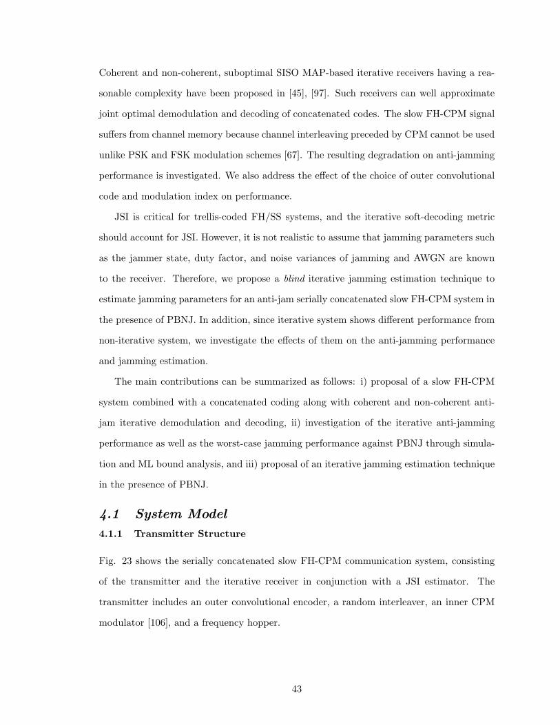
Coherent and non-coherent, suboptimal SISO MAP-based iterative receivers having a rea-
sonable complexity have been proposed in [45], [97]. Such receivers can well approximate
joint optimal demodulation and decoding of concatenated codes. The slow FH-CPM signal
suffers from channel memory because channel interleaving preceded by CPM cannot be used
unlike PSK and FSK modulation schemes [67]. The resulting degradation on anti-jamming
performance is investigated. We also address the effect of the choice of outer convolutional
code and modulation index on performance.
JSI is critical for trellis-coded FH/SS systems, and the iterative soft-decoding metric
should account for JSI. However, it is not realistic to assume that jamming parameters such
as the jammer state, duty factor, and noise variances of jamming and AWGN are known
to the receiver. Therefore, we propose a blind iterative jamming estimation technique to
estimate jamming parameters for an anti-jam serially concatenated slow FH-CPM system in
the presence of PBNJ. In addition, since iterative system shows different performance from
non-iterative system, we investigate the effects of them on the anti-jamming performance
and jamming estimation.
The main contributions can be summarized as follows: i) proposal of a slow FH-CPM
system combined with a concatenated coding along with coherent and non-coherent anti-
jam iterative demodulation and decoding, ii) investigation of the iterative anti-jamming
performance as well as the worst-case jamming performance against PBNJ through simula-
tion and ML bound analysis, and iii) proposal of an iterative jamming estimation technique
in the presence of PBNJ.
4.1 System Model
4.1.1 Transmitter Structure
Fig. 23 shows the serially concatenated slow FH-CPM communication system, consisting
of the transmitter and the iterative receiver in conjunction with a JSI estimator. The
transmitter includes an outer convolutional encoder, a random interleaver, an inner CPM
modulator [106], and a frequency hopper.
43
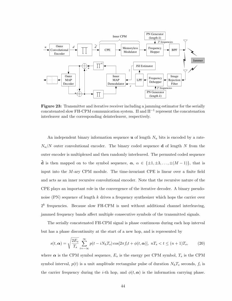
Outer
Convolutional
Encoder
Memoryless
Modulator CPE
u Frequency
Hopper
PN Generator
(length k ) Inner CPM
BPF
2 k frequencies
d d
Inner
MAP
Demodulator
Outer
MAP
Decoder
Frequency
Dehopper
PN Generator
(length k )
2 k frequencies
LPF
Image
Rejection
Filter
JSI Estimator
r
+
+ -
- z
Jammer
Figure 23: Transmitter and iterative receiver including a jamming estimator for the seriallyconcatenated slow FH-CPM communication system. Π and Π−1 represent the concatenationinterleaver and the corresponding deinterleaver, respectively.
An independent binary information sequence u of length Nu bits is encoded by a rate-
Nu/N outer convolutional encoder. The binary coded sequence d of length N from the
outer encoder is multiplexed and then randomly interleaved. The permuted coded sequence
d is then mapped on to the symbol sequence, α, α ∈ {±1,±3, . . . ,±(M − 1)}, that is
input into the M -ary CPM module. The time-invariant CPE is linear over a finite field
and acts as an inner recursive convolutional encoder. Note that the recursive nature of the
CPE plays an important role in the convergence of the iterative decoder. A binary pseudo-
noise (PN) sequence of length k drives a frequency synthesizer which hops the carrier over
2k frequencies. Because slow FH-CPM is used without additional channel interleaving,
jammed frequency bands affect multiple consecutive symbols of the transmitted signals.
The serially concatenated FH-CPM signal is phase continuous during each hop interval
but has a phase discontinuity at the start of a new hop, and is represented by
s(t, α) =
√
2Es
Ts
∞∑
i=−∞p(t − iNhTs) cos[2πfit + φ(t, α)], nTs < t ≤ (n + 1)Ts, (20)
where α is the CPM symbol sequence, Es is the energy per CPM symbol, Ts is the CPM
symbol interval, p(t) is a unit amplitude rectangular pulse of duration NhTs seconds, fi is
the carrier frequency during the i-th hop, and φ(t, α) is the information carrying phase.
44

Note that hop dwell interval is Th = NhTs = 1/Rh.
4.1.2 Anti-Jam Coherent and Non-Coherent Iterative Receivers
PBNJ is one of the most effective jamming strategies against FH systems. A PBNJ spreads
noise of total power of J evenly over a frequency range of bandwidth WJ , which is a subset
of the full spread bandwidth Wss. The jammer determines its duty factor, ρ△= WJ/Wss ∈
(0, 1], to maximize the system degradation. Because the pseudo-random FH is assumed to
be used to produce uniform FH slot usage, the PBNJ can be modeled as a two state model
and is independent from hop to hop. During a FH dwell time of Th, let us define the jammer
state random variable, z, where the hop is jammed with probability of P (z = 1) = ρ, and
unjammed with probability of P (z = 0) = 1 − ρ. It is also assumed that the JSI yields
the knowledge regarding the jamming state of the CPM symbols except of FH pattern and
phase. JSI plays an important role in the SISO IDD process since a smart jammer can
completely destroy a link even with minimal jammer power if JSI is not utilized.
The received FH-CPM signal is passed through a wideband image rejection filter. After-
wards, it is dehopped synchronously with a locally generated reference signal, which is given
by fR(t) = 2∑∞
i=−∞ p(t − iNhTs) cos[2π(fi + fIF)t] where fIF represents an intermediate
carrier frequency. Therefore, the received dehopped complex CPM signal during the i-th
hop in the presence of the PBNJ is
ri(t) =
√
2Es
Tscos[2πfIFt + φi(t, α) + θi] + ni(t), iNhTs < t ≤ (i + 1)NhTs, (21)
where ni ∼ N (0, N0/2+ziNJ/2ρ) is the sum of double-sided AWGN and jamming noise and
the random phase θi is assumed to be constant during the i-th hop interval but independent
from hop to hop.
The MAP-based IDD is a SISO process that utilizes a priori symbol probabilities at its
input and produces soft information at its output. The refined input symbol probabilities
are fed back to the decoder as a priori information [45], [97]. Coherent and non-coherent
reception schemes are applied to the proposed FH-CPM system. In practice, a pilot symbol-
aided detection technique can be used for coherent reception [53]. Given the dehopped
discrete complex sequence r = [r0, . . . , rNf−1], where ri = [ri0, . . . , r
iNh−1] and Nf denotes
45
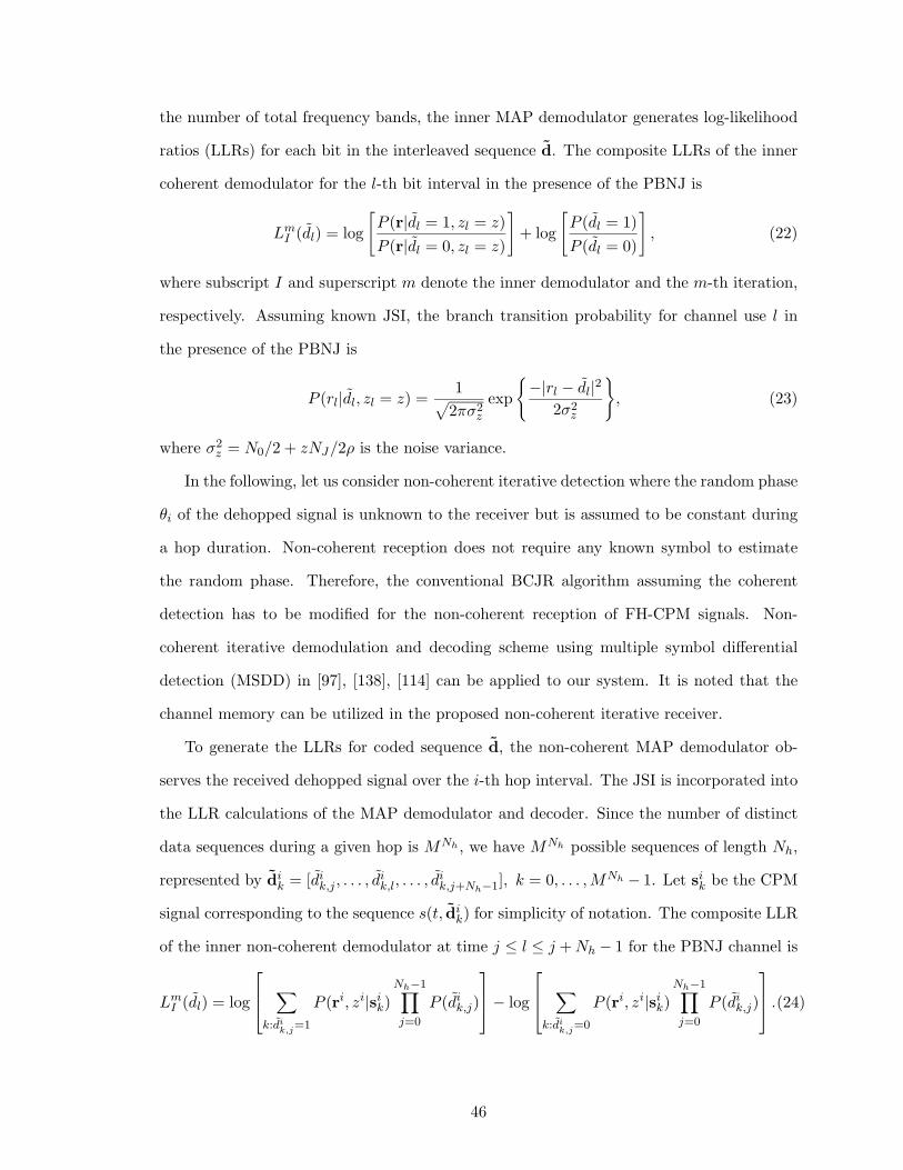
the number of total frequency bands, the inner MAP demodulator generates log-likelihood
ratios (LLRs) for each bit in the interleaved sequence d. The composite LLRs of the inner
coherent demodulator for the l-th bit interval in the presence of the PBNJ is
LmI (dl) = log
[
P (r|dl = 1, zl = z)
P (r|dl = 0, zl = z)
]
+ log
[
P (dl = 1)
P (dl = 0)
]
, (22)
where subscript I and superscript m denote the inner demodulator and the m-th iteration,
respectively. Assuming known JSI, the branch transition probability for channel use l in
the presence of the PBNJ is
P (rl|dl, zl = z) =1
√
2πσ2z
exp
{
−|rl − dl|22σ2
z
}
, (23)
where σ2z = N0/2 + zNJ/2ρ is the noise variance.
In the following, let us consider non-coherent iterative detection where the random phase
θi of the dehopped signal is unknown to the receiver but is assumed to be constant during
a hop duration. Non-coherent reception does not require any known symbol to estimate
the random phase. Therefore, the conventional BCJR algorithm assuming the coherent
detection has to be modified for the non-coherent reception of FH-CPM signals. Non-
coherent iterative demodulation and decoding scheme using multiple symbol differential
detection (MSDD) in [97], [138], [114] can be applied to our system. It is noted that the
channel memory can be utilized in the proposed non-coherent iterative receiver.
To generate the LLRs for coded sequence d, the non-coherent MAP demodulator ob-
serves the received dehopped signal over the i-th hop interval. The JSI is incorporated into
the LLR calculations of the MAP demodulator and decoder. Since the number of distinct
data sequences during a given hop is MNh , we have MNh possible sequences of length Nh,
represented by dik = [di
k,j , . . . , dik,l, . . . , d
ik,j+Nh−1], k = 0, . . . , MNh − 1. Let si
k be the CPM
signal corresponding to the sequence s(t, dik) for simplicity of notation. The composite LLR
of the inner non-coherent demodulator at time j ≤ l ≤ j + Nh − 1 for the PBNJ channel is
LmI (dl) = log
∑
k:dik,j
=1
P (ri, zi|sik)
Nh−1∏
j=0
P (dik,j)
− log
∑
k:dik,j
=0
P (ri, zi|sik)
Nh−1∏
j=0
P (dik,j)
.(24)
46
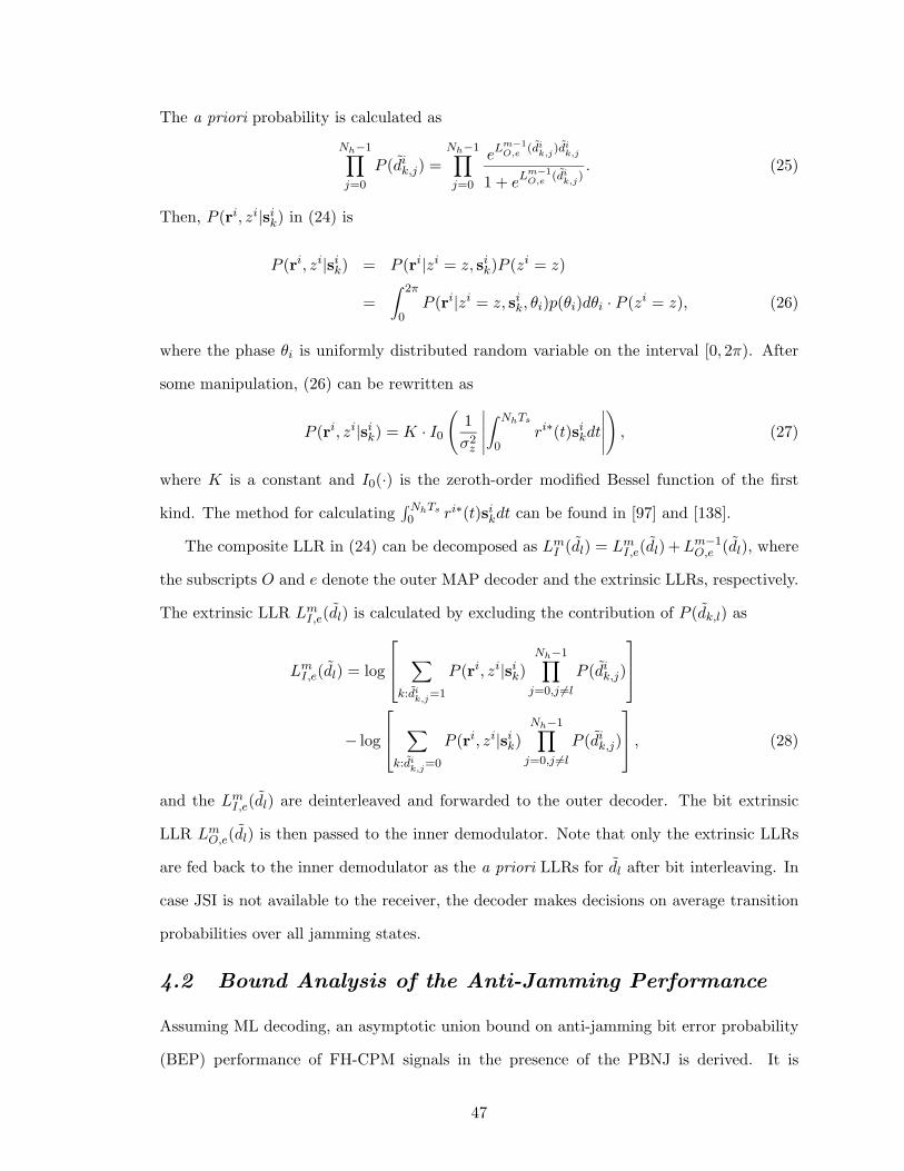
The a priori probability is calculated as
Nh−1∏
j=0
P (dik,j) =
Nh−1∏
j=0
eLm−1O,e (di
k,j)dik,j
1 + eLm−1O,e (di
k,j). (25)
Then, P (ri, zi|sik) in (24) is
P (ri, zi|sik) = P (ri|zi = z, si
k)P (zi = z)
=
∫ 2π
0P (ri|zi = z, si
k, θi)p(θi)dθi · P (zi = z), (26)
where the phase θi is uniformly distributed random variable on the interval [0, 2π). After
some manipulation, (26) can be rewritten as
P (ri, zi|sik) = K · I0
(
1
σ2z
∣
∣
∣
∣
∣
∫ NhTs
0ri∗(t)si
kdt
∣
∣
∣
∣
∣
)
, (27)
where K is a constant and I0(·) is the zeroth-order modified Bessel function of the first
kind. The method for calculating∫NhTs0 ri∗(t)si
kdt can be found in [97] and [138].
The composite LLR in (24) can be decomposed as LmI (dl) = Lm
I,e(dl) + Lm−1O,e (dl), where
the subscripts O and e denote the outer MAP decoder and the extrinsic LLRs, respectively.
The extrinsic LLR LmI,e(dl) is calculated by excluding the contribution of P (dk,l) as
LmI,e(dl) = log
∑
k:dik,j
=1
P (ri, zi|sik)
Nh−1∏
j=0,j 6=l
P (dik,j)
− log
∑
k:dik,j
=0
P (ri, zi|sik)
Nh−1∏
j=0,j 6=l
P (dik,j)
, (28)
and the LmI,e(dl) are deinterleaved and forwarded to the outer decoder. The bit extrinsic
LLR LmO,e(dl) is then passed to the inner demodulator. Note that only the extrinsic LLRs
are fed back to the inner demodulator as the a priori LLRs for dl after bit interleaving. In
case JSI is not available to the receiver, the decoder makes decisions on average transition
probabilities over all jamming states.
4.2 Bound Analysis of the Anti-Jamming Performance
Assuming ML decoding, an asymptotic union bound on anti-jamming bit error probability
(BEP) performance of FH-CPM signals in the presence of the PBNJ is derived. It is
47
quite difficult to analyze exactly the error performance of an iterative system for a specific
interleaver at low-to-moderate SNR. For large Nh, the performance of the non-coherent
receiver performs to within a half dB that of the coherent receiver, as will be shown in Fig.
27. Therefore, a framework similar to the analysis for a serially concatenated convolutional
code using the ensemble input-output transfer function (IOWEF) bounding technique and
a hypothetical averaging uniform interleaver [97], [126], [13] is used.
Given the outer code with the code rate of Ro = m/n, the union bound for the BEP
assuming the ML soft-decision decoder is
Pb ≤N∑
d=dm
NRo∑
w=wom
w
NRoAw,dPpw(d), (29)
where dm is the minimum weight of all codewords, wom is the minimum weight of an input
sequence generating an error event of the outer code, Ppw(d) represents the pairwise error
probability (PEP), and Aw,d represents the overall IOWEF that is based on the use of the
uniform interleaver1 of length N . The detailed calculation of the IOWEF can be found in
Appendix A, and the value of the minimum weight dm of a length-N compound error event
is calculated from
dm = minα,α
{
1
2Eb
∫ NTs
0|s(t, α) − s(t, α)|2dt
}
= minα,α
{
log2 M
Ts
∫ NTs
0[1 − cos ∆φ(t)]dt
}
, (30)
where ∆φ(t) denotes the phase difference between the coded FH-CPM signals. Finally, the
PEP Ppw(d) in (29) in the presence of the PBNJ is calculated by conditioning on the event
that k of d symbols are jammed as
Ppw(d) =d∑
k=0
(
d
k
)
ρk(1 − ρ)d−k · Q(√
EbR
[
k
σ21
+d − k
σ20
]
)
, (31)
where R is the overall code rate and Q(·) denotes the Q-function. For a receiver operat-
ing without JSI, the receiver makes bit decisions by summing the channel outputs. The
corresponding PEP is
Ppw(d) =d∑
k=0
(
d
k
)
ρk(1 − ρ)d−k · Q(√
EbRdkdσ2
1 + d−kd σ2
0
)
. (32)
1The uniform interleaving is devised in [13] to map a given input sequence of length N and weight l intoits all distinct
(
Nl
)
permutations with equal probability of 1/(
Nl
)
= l!(N − l)!/N !.
48
4.3 An Iterative Jamming Estimation Technique
An important issue in the design of a FH system is the generation of jammer information
such as the jammer state, duty factor, and noise variances of jamming and AWGN. A jam-
ming estimation technique is required to generate jammer state estimates that are used to
weight the branch metrics in an iterative receiver. It is promising that the anti-jamming
performance can be further improved by incorporating the jammer information with iter-
ative processing. Since random FH pattern is known to the coherent receiver, we need to
estimate jamming states z, duty factor ρ, and the noise variances of jamming noise and
AWGN σ2z (z = 0, 1) for the jamming estimation.
Given the dehopped discrete complex sequence r = [r0, . . . , rN ′
f−1], where ri = [ri0, . . . , r
iNh−1]
and N ′f denotes the number of total frequency bands, we first calculate the ratio of jammer
state estimates P (zi = 1|ri)/P (zi = 0|ri) from the received signal and pass this along with
data bit estimates between demodulator and decoder. As decoding iterations proceed, we
obtain more refined jammer state estimates as well as more refined data bit estimates. Let
us define a log-probability ratio Lm(zi) for the i-th hop during m-th iteration as
Lm(zi) = log
[
P (zi = 1|ri)
P (zi = 0|ri)
]
, (33)
= log
[
P (ri|zi = 1)P (zi = 1)
P (ri|zi = 0)P (zi = 0)
]
, (34)
where
P (ri|zi = z) =Nh−1∏
l=0
1√
2πσ2z
exp
{
− 1
2σ2z
|ril − sign(ri
l)|2}
, (35)
=1
(2πσ2z)
Nh/2exp
− 1
2σ2z
Nh−1∑
l=0
|ril − sign(ri
l)|2
, (36)
where i = 0, . . . , N ′f −1 and σ2
z = N0/2+zNJ/2ρ is the noise variance. At the first iteration,
initial duty factor of 0.5 and Eb/N0 and Eb/NJ offsets relative to the true Eb/N0 and Eb/NJ
are used since they are unknown. Further, defining V i =∑Nh−1
l=0 |ril − sign(ri
l)|2/2Nh, we
can rewrite (34) as
Lm(zi) = log
{
ρ
1 − ρ· σNh
0
σNh1
· exp[
(σ−20 − σ−2
1 )NhV i]
}
. (37)
49

This yields a log-likelihood threshold test for the jammer state estimate, where the i-th hop
jammed is deemed to be jammed if V i > ǫ, or unjammed otherwise. The threshold ǫ can
be obtained by equating (37) to zero, such that
ǫ = Kσ ·{
1
2log
(
σ21
σ20
)
+1
Nhlog
(
1 − ρ
ρ
)
}
, (38)
where Kσ = σ21σ
20/(σ2
1 − σ20). Note that the threshold, epsilon, is updated every iteration.
As a result, duty factor ρ is updated by counting the estimated z such that
ρ =N ′
1
N ′f
, N ′0 + N ′
1 = N ′f , (39)
where N ′1 and N ′
0 denote the numbers of jammed hops and unjammed hops, respectively.
Having the JSI and duty factor, we can estimate the noise variances of jamming and
AWGN, σ21 and σ2
0, in case that the noise variances are unknown to the receiver, i.e.,
σ21 =
1
N ′1
∑
i∈ZJ
(i+1)Nh−1∑
l=iNh
|ril − sign(ri
l)|2/2Nh, (40)
and
σ20 =
1
N ′0
∑
i/∈ZJ
(i+1)Nh−1∑
l=iNh
|ril − sign(ri
l)|2/2Nh, (41)
where ZJ denotes a set of jammed hops. Once the jamming state and jamming noise
variance have been estimated, they are used in the soft-input soft-output (SISO) maximum
a posteriori (MAP)-based IDD process that utilizes a priori symbol probabilities at its input
and produces soft information at its output. The flowchart for the jamming estimation is
illustrated in Fig. 24.
4.4 Numerical Results and Discussions
In this section, we present the simulation and analysis results of the anti-jamming per-
formance. For the purpose of comparison with other systems, a rate-1/2 non-recursive
and non-systematic convolutional code with octal generator polynomials of (7, 5) and full-
response binary CPFSK with modulation index h = 1/2 are used for the reference outer
code and inner CPM, respectively. Although we limit ourselves to binary CPFSK, results
can be extended to M -ary CPM schemes. The information block length is 1000 bits and the
50
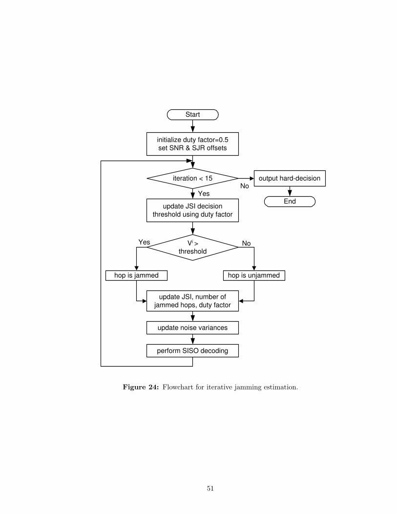
Start
initialize duty factor=0.5
set SNR & SJR offsets
iteration < 15
V i >
threshold
No
hop is jammed hop is unjammed
update JSI, number of
jammed hops, duty factor
No Yes
update noise variances
perform SISO decoding
update JSI decision
threshold using duty factor
Yes
output hard-decision
End
Figure 24: Flowchart for iterative jamming estimation.
51
maximum number of iterations at the receiver is set to 15. It is also assumed that perfect
JSI is available at the receiver, unless stated otherwise. The background thermal noise in
the presence of the PBNJ is set to 20 dB since the jamming noise is dominant. In addition,
perfect symbol and carrier synchronization and timing recovery are assumed.
4.4.1 Effect of the Slow FH Channel on the Anti-Jamming Performance
The proposed system will experience performance degradation due to slow FH memory
channel unlike the case of the usual memoryless channel. The degradation of the anti-
jamming performance induced by the slow FH block interference is investigated. Fig. 25
shows how the anti-jamming performance for the coherent iterative receiver depends on the
the number of symbols per hop Nh (= 1 ∼ 20)2 and the duty factor ρ. The y-axis represents
a required Eb/NJ needed to achieve the target BER=10−3. The optimal jamming corre-
sponds to ρ = 1.0 regardless of Nh. It means that the worst-case error performance occurs
when all symbols are jammed. The reduced number of hops per transmitted codeword, de-
noted by Nc, leads to decrease of the benefit by independent hopping and the degradation
of the MAP algorithm due to the memory channel. However, little additional degradation
is observed for the case of Nh ≥ 10. It was shown by spectral analysis in [71] that, for
the slow FH-CPM waveforms, a more compact dehopped power density spectrum can be
obtained as the number of symbols per hop Nh increases. The 99%-power bandwidth of a
frequency-hopped MSK signal for Nh =20, 10, and 5 is greater than 1.5, 2, and 4 times,
respectively, greater that of an MSK signal without FH. In the following, we set Nh to
20 to provide a good trade-off between bandwidth-efficiency and power-efficiency of FH
waveforms, unless stated otherwise.
4.4.2 Anti-Jamming Performance of the Iterative Receivers
The worst-case jamming performance of the coherent iterative receiver, represented as
Pwcb = Pb(ρ)|ρ=ρwc , is shown in Fig. 26. As the iteration in the receiver increases, the
required Eb/NJ decreases and thus a good anti-jamming capability can be achieved.
2The corresponding numbers of hops per codeword, denoted by Nc, for Nh =1, 5, 10, and 20 are 2000,400, 200, and 100 hops, respectively.
52
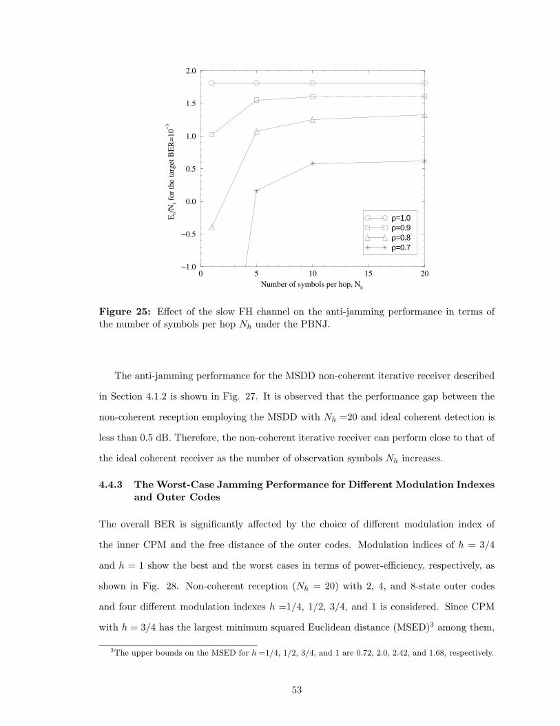
0 5 10 15 20
Number of symbols per hop, Nh
−1.0
−0.5
0.0
0.5
1.0
1.5
2.0
Eb/N
J fo
r th
e ta
rget
BE
R=
10
−3
ρ=1.0 ρ=0.9 ρ=0.8 ρ=0.7
Figure 25: Effect of the slow FH channel on the anti-jamming performance in terms ofthe number of symbols per hop Nh under the PBNJ.
The anti-jamming performance for the MSDD non-coherent iterative receiver described
in Section 4.1.2 is shown in Fig. 27. It is observed that the performance gap between the
non-coherent reception employing the MSDD with Nh =20 and ideal coherent detection is
less than 0.5 dB. Therefore, the non-coherent iterative receiver can perform close to that of
the ideal coherent receiver as the number of observation symbols Nh increases.
4.4.3 The Worst-Case Jamming Performance for Different Modulation Indexes
and Outer Codes
The overall BER is significantly affected by the choice of different modulation index of
the inner CPM and the free distance of the outer codes. Modulation indices of h = 3/4
and h = 1 show the best and the worst cases in terms of power-efficiency, respectively, as
shown in Fig. 28. Non-coherent reception (Nh = 20) with 2, 4, and 8-state outer codes
and four different modulation indexes h =1/4, 1/2, 3/4, and 1 is considered. Since CPM
with h = 3/4 has the largest minimum squared Euclidean distance (MSED)3 among them,
3The upper bounds on the MSED for h =1/4, 1/2, 3/4, and 1 are 0.72, 2.0, 2.42, and 1.68, respectively.
53
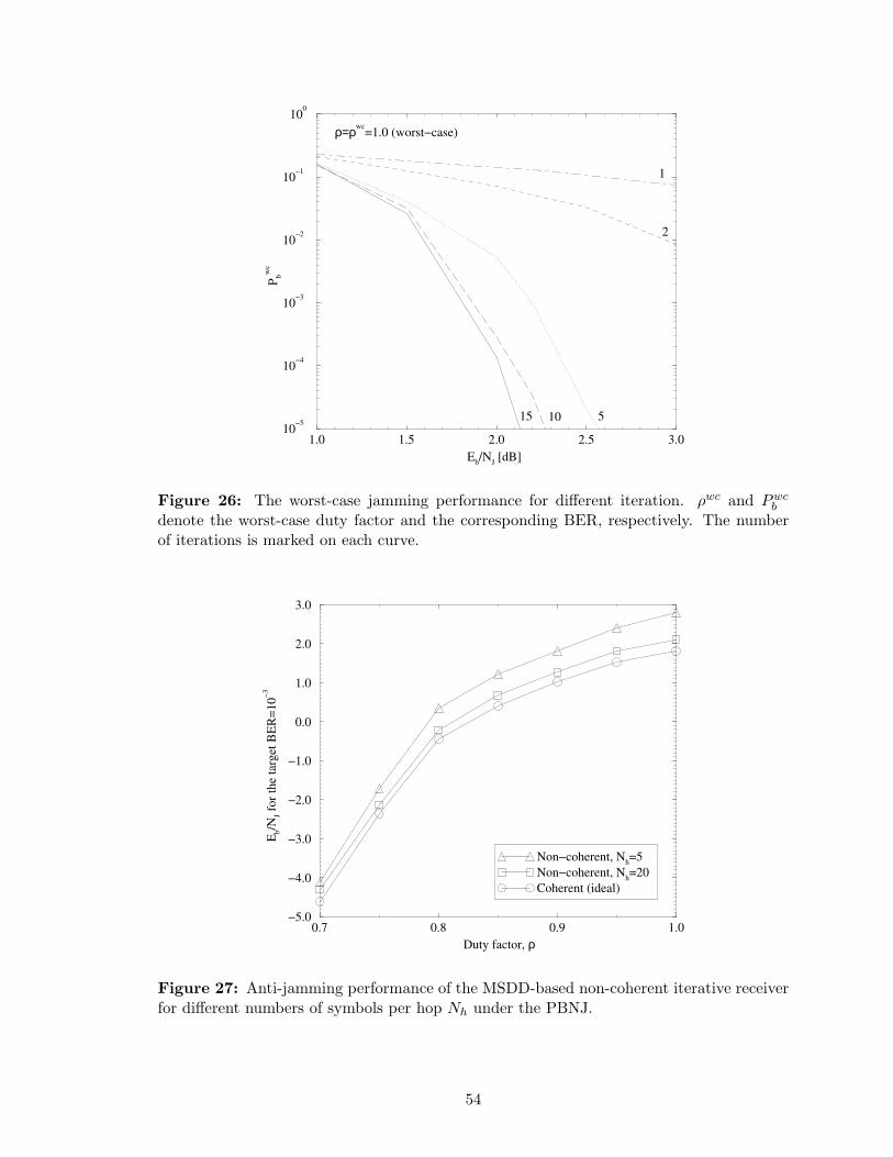
1.0 1.5 2.0 2.5 3.0
Eb/N
J [dB]
10−5
10−4
10−3
10−2
10−1
100
Pb
wc
1
ρ=ρwc=1.0 (worst−case)
2
51015
Figure 26: The worst-case jamming performance for different iteration. ρwc and Pwcb
denote the worst-case duty factor and the corresponding BER, respectively. The numberof iterations is marked on each curve.
0.7 0.8 0.9 1.0
Duty factor, ρ
−5.0
−4.0
−3.0
−2.0
−1.0
0.0
1.0
2.0
3.0
Eb/N
J fo
r th
e ta
rget
BE
R=
10
−3
Non−coherent, Nh=5
Non−coherent, Nh=20
Coherent (ideal)
Figure 27: Anti-jamming performance of the MSDD-based non-coherent iterative receiverfor different numbers of symbols per hop Nh under the PBNJ.
54
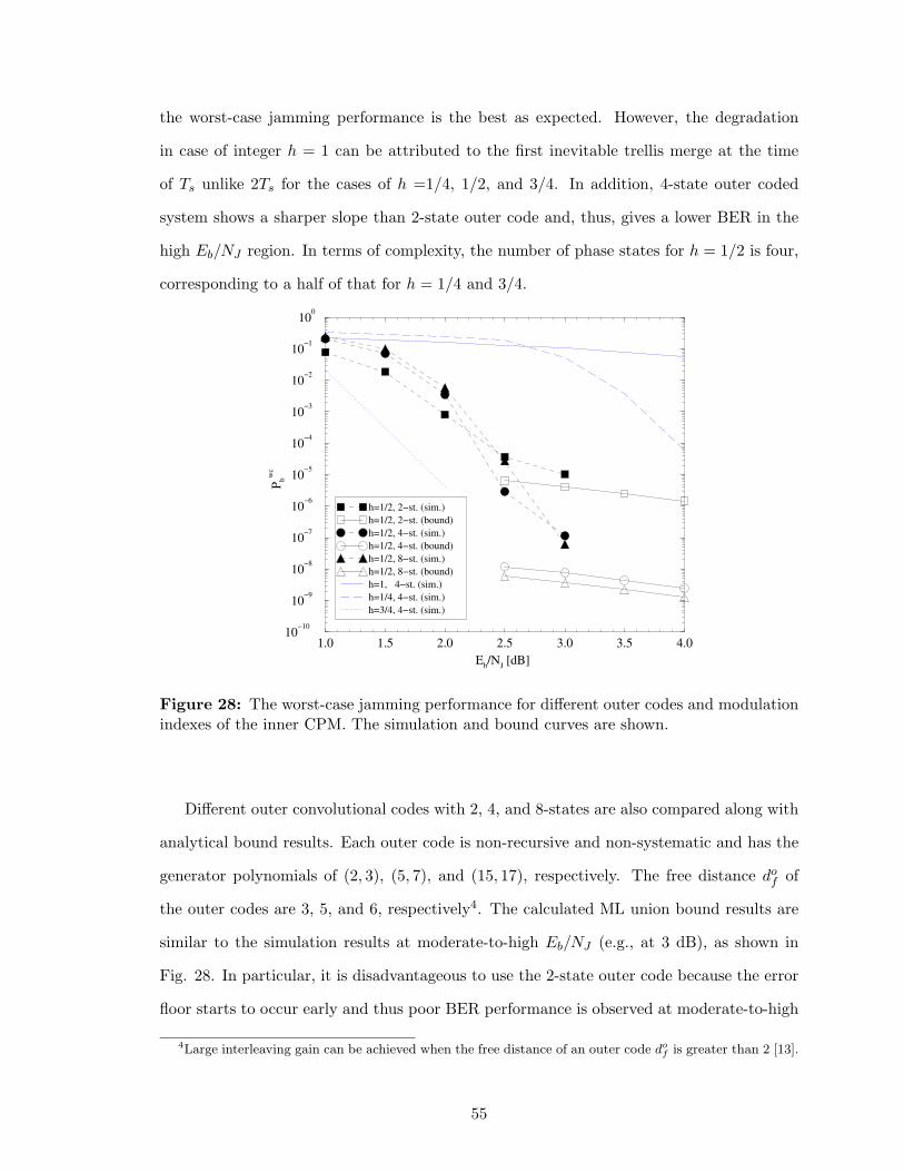
the worst-case jamming performance is the best as expected. However, the degradation
in case of integer h = 1 can be attributed to the first inevitable trellis merge at the time
of Ts unlike 2Ts for the cases of h =1/4, 1/2, and 3/4. In addition, 4-state outer coded
system shows a sharper slope than 2-state outer code and, thus, gives a lower BER in the
high Eb/NJ region. In terms of complexity, the number of phase states for h = 1/2 is four,
corresponding to a half of that for h = 1/4 and 3/4.
1.0 1.5 2.0 2.5 3.0 3.5 4.0
Eb/N
J [dB]
10−10
10−9
10−8
10−7
10−6
10−5
10−4
10−3
10−2
10−1
100
Pb
wc
h=1/2, 2−st. (sim.)
h=1/2, 2−st. (bound)
h=1/2, 4−st. (sim.)
h=1/2, 4−st. (bound)
h=1/2, 8−st. (sim.)
h=1/2, 8−st. (bound)
h=1, 4−st. (sim.)
h=1/4, 4−st. (sim.)
h=3/4, 4−st. (sim.)
Figure 28: The worst-case jamming performance for different outer codes and modulationindexes of the inner CPM. The simulation and bound curves are shown.
Different outer convolutional codes with 2, 4, and 8-states are also compared along with
analytical bound results. Each outer code is non-recursive and non-systematic and has the
generator polynomials of (2, 3), (5, 7), and (15, 17), respectively. The free distance dof of
the outer codes are 3, 5, and 6, respectively4. The calculated ML union bound results are
similar to the simulation results at moderate-to-high Eb/NJ (e.g., at 3 dB), as shown in
Fig. 28. In particular, it is disadvantageous to use the 2-state outer code because the error
floor starts to occur early and thus poor BER performance is observed at moderate-to-high
4Large interleaving gain can be achieved when the free distance of an outer code dof is greater than 2 [13].
55
Eb/NJ . However, as we can see the simulation results for low-to-moderate Eb/NJ region,
an outer code with larger state (or larger free distance) does not necessary provide better
anti-jamming performance. This result below Eb/NJ corresponding to the waterfall region
is shown to be rather different from the bound analysis. The error performance of turbo-
like code is not only determined by whole distance spectrum5, but also by the convergence
characteristics of component codes. For low-to-moderate SNR, an outer code with larger
memory is more likely to stuck early during iterations [27]. Therefore, it results in the
degradation of iterative anti-jamming performance.
4.4.4 Anti-Jamming Performance of Jamming Estimation
Fig. 29 shows the anti-jamming performance for the cases with different jamming parame-
ters. The y-axis represents a required Eb/NJ needed to achieve the target BER=10−3. The
proposed jamming estimation technique is used to estimate jamming states as well as the
noise variances of jamming and AWGN. The cases with perfect JSI and noise variances can
be regarded as the lower bounds on the anti-jamming performance since both the JSI and
noise variances are completely known to the receiver. Since the anti-jamming performance
for the jamming estimation degrades with the increase in the offset, we plot curves for dif-
ferent offsets (i.e., 0, 2, and 4 dB). The offset of 0 dB means that the noise variances are
known. The JSI estimation case with 4 dB offset only looses less than 1 dB relative to the
case with the perfect JSI for ρ ≤ 0.7. In addition, for the cases with the JSI estimation,
the required Eb/NJ decreases as ρ decreases in contrast to the case without the JSI estima-
tion. For no JSI cases, two cases with known and unknown duty factor are here considered.
They show almost same performance regardless of the duty factor information. The result
confirms that the proposed jamming estimation technique assists the iterative decoding pro-
cess and thus improves the anti-jamming performance as the iteration increases. Therefore,
the anti-jamming performance of iterative soft-decision decoding is highly dependent of the
availability of the JSI.
5Turbo-like codes have usually a different spectrum shape from random codes, especially for low-to-moderate weight (see [110] and references therein).
56
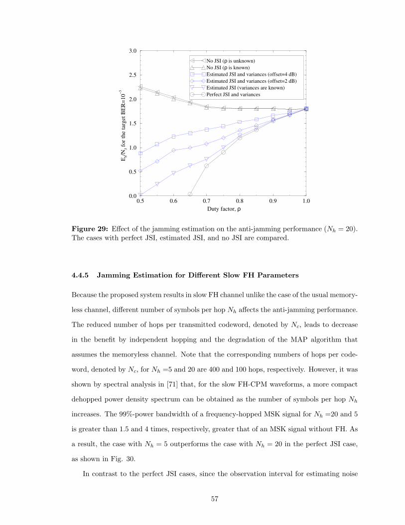
0.5 0.6 0.7 0.8 0.9 1.0
Duty factor, ρ
0.0
0.5
1.0
1.5
2.0
2.5
3.0
Eb/N
J fo
r th
e ta
rget
BE
R=
10
−3
No JSI (ρ is unknown)
No JSI (ρ is known)
Estimated JSI and variances (offset=4 dB)
Estimated JSI and variances (offset=2 dB)
Estimated JSI (variances are known)
Perfect JSI and variances
Figure 29: Effect of the jamming estimation on the anti-jamming performance (Nh = 20).The cases with perfect JSI, estimated JSI, and no JSI are compared.
4.4.5 Jamming Estimation for Different Slow FH Parameters
Because the proposed system results in slow FH channel unlike the case of the usual memory-
less channel, different number of symbols per hop Nh affects the anti-jamming performance.
The reduced number of hops per transmitted codeword, denoted by Nc, leads to decrease
in the benefit by independent hopping and the degradation of the MAP algorithm that
assumes the memoryless channel. Note that the corresponding numbers of hops per code-
word, denoted by Nc, for Nh =5 and 20 are 400 and 100 hops, respectively. However, it was
shown by spectral analysis in [71] that, for the slow FH-CPM waveforms, a more compact
dehopped power density spectrum can be obtained as the number of symbols per hop Nh
increases. The 99%-power bandwidth of a frequency-hopped MSK signal for Nh =20 and 5
is greater than 1.5 and 4 times, respectively, greater that of an MSK signal without FH. As
a result, the case with Nh = 5 outperforms the case with Nh = 20 in the perfect JSI case,
as shown in Fig. 30.
In contrast to the perfect JSI cases, since the observation interval for estimating noise
57
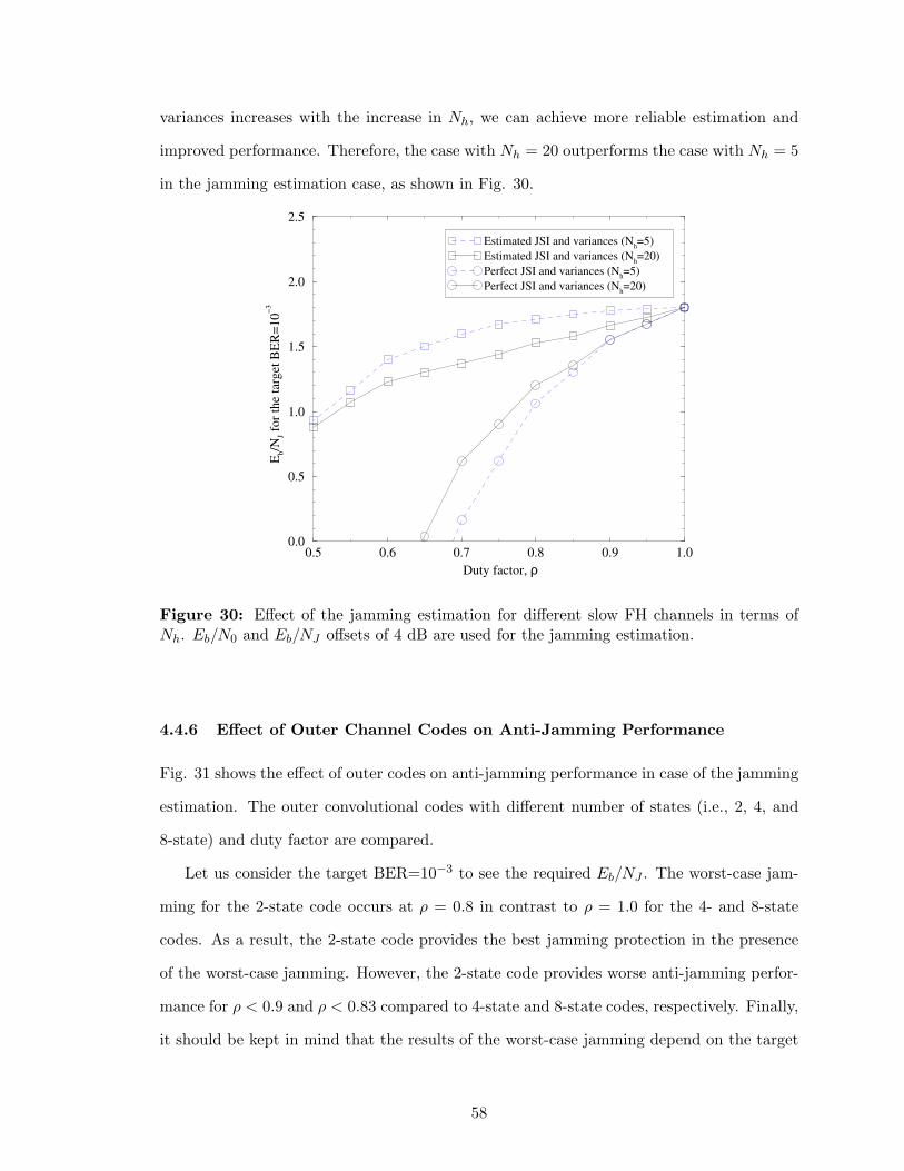
variances increases with the increase in Nh, we can achieve more reliable estimation and
improved performance. Therefore, the case with Nh = 20 outperforms the case with Nh = 5
in the jamming estimation case, as shown in Fig. 30.
0.5 0.6 0.7 0.8 0.9 1.0
Duty factor, ρ
0.0
0.5
1.0
1.5
2.0
2.5
Eb/N
J fo
r th
e ta
rget
BE
R=
10
−3
Estimated JSI and variances (Nh=5)
Estimated JSI and variances (Nh=20)
Perfect JSI and variances (Nh=5)
Perfect JSI and variances (Nh=20)
Figure 30: Effect of the jamming estimation for different slow FH channels in terms ofNh. Eb/N0 and Eb/NJ offsets of 4 dB are used for the jamming estimation.
4.4.6 Effect of Outer Channel Codes on Anti-Jamming Performance
Fig. 31 shows the effect of outer codes on anti-jamming performance in case of the jamming
estimation. The outer convolutional codes with different number of states (i.e., 2, 4, and
8-state) and duty factor are compared.
Let us consider the target BER=10−3 to see the required Eb/NJ . The worst-case jam-
ming for the 2-state code occurs at ρ = 0.8 in contrast to ρ = 1.0 for the 4- and 8-state
codes. As a result, the 2-state code provides the best jamming protection in the presence
of the worst-case jamming. However, the 2-state code provides worse anti-jamming perfor-
mance for ρ < 0.9 and ρ < 0.83 compared to 4-state and 8-state codes, respectively. Finally,
it should be kept in mind that the results of the worst-case jamming depend on the target
58
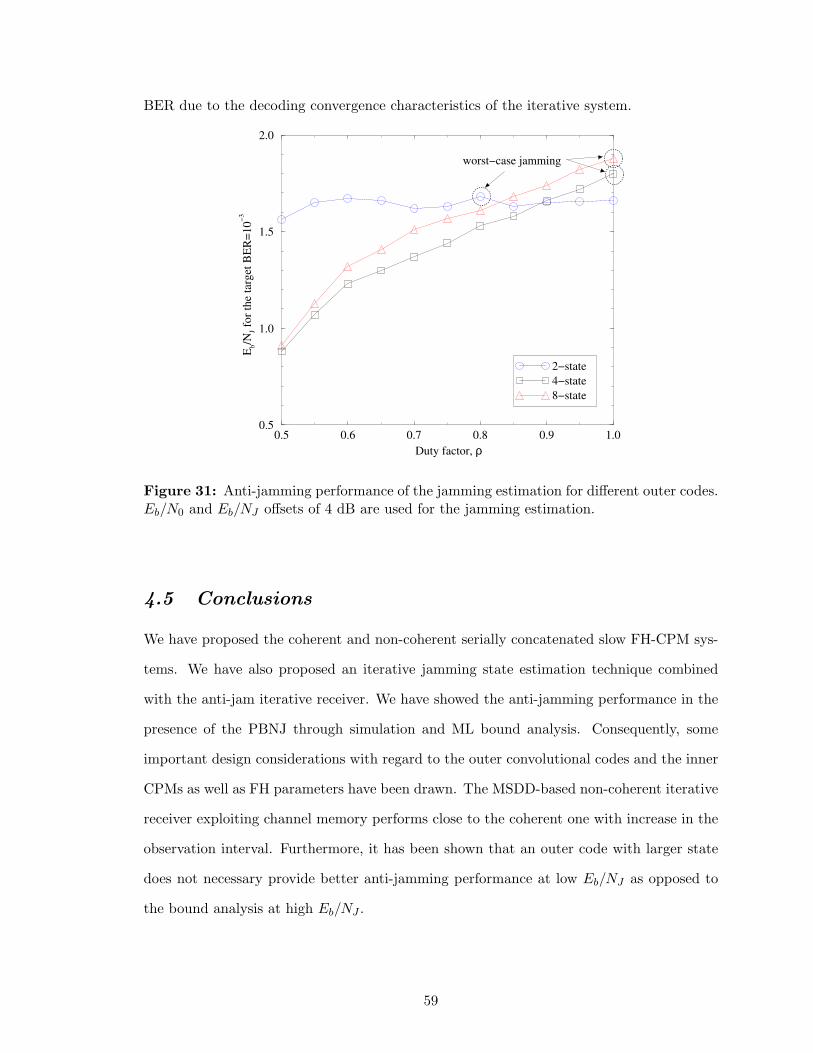
BER due to the decoding convergence characteristics of the iterative system.
0.5 0.6 0.7 0.8 0.9 1.0
Duty factor, ρ
0.5
1.0
1.5
2.0
Eb/N
J fo
r th
e ta
rget
BE
R=
10
−3
2−state
4−state
8−state
worst−case jamming
Figure 31: Anti-jamming performance of the jamming estimation for different outer codes.Eb/N0 and Eb/NJ offsets of 4 dB are used for the jamming estimation.
4.5 Conclusions
We have proposed the coherent and non-coherent serially concatenated slow FH-CPM sys-
tems. We have also proposed an iterative jamming state estimation technique combined
with the anti-jam iterative receiver. We have showed the anti-jamming performance in the
presence of the PBNJ through simulation and ML bound analysis. Consequently, some
important design considerations with regard to the outer convolutional codes and the inner
CPMs as well as FH parameters have been drawn. The MSDD-based non-coherent iterative
receiver exploiting channel memory performs close to the coherent one with increase in the
observation interval. Furthermore, it has been shown that an outer code with larger state
does not necessary provide better anti-jamming performance at low Eb/NJ as opposed to
the bound analysis at high Eb/NJ .
59
CHAPTER V
TURBO-LIKE CODED MULTI-H CPM
Multi-h CPM [5], [8] is a generalization of single-h CPM, wherein the modulation index is
cyclically changed for successive symbol intervals. A properly chosen cyclic set of modu-
lation indexes results in delayed merging of neighboring phase trellis paths and, therefore,
provides a larger minimum Euclidean distance than conventional single-h CPM. The error
performance for uncoded multi-h CPM schemes on AWGN and flat fading channels were
presented in [130] and [135], respectively. Convolutionally coded multi-h CPM schemes
using a Viterbi decoder were considered in [36].
Serial concatenated interleaved convolutional codes and their variants have been devel-
oped that concatenate and outer convolutional code, an interleaver, and a recursive inner
code [13], [26]. With iterative decoding, serial turbo codes exhibit exceptionally good error
performance, particularly at low-to-moderate SNR and for very large interleaver sizes. The
serial turbo coding concept has been extended to iterative demodulation and decoding by
replacing the recursive inner code of a serial turbo code with a recursive modulator, such
as a CPM modulator (e.g., [45]-[94]). Existing serially concatenated CPM schemes use
a single-h CPM modulator. We extends serially concatenated single-h CPM schemes to
multi-h CPM [64].
The ML upper bounds on error probability [13] and convergence analysis [27] are two
widely used analytical techniques for turbo-like codes. The former is useful for characterizing
the error-floor region, while the latter is useful for characterizing the water-fall region. We
utilizes both of these analytical approaches to better understand serially concatenated multi-
h CPM schemes with iterative demodulation and decoding, presenting new observations and
results.
60
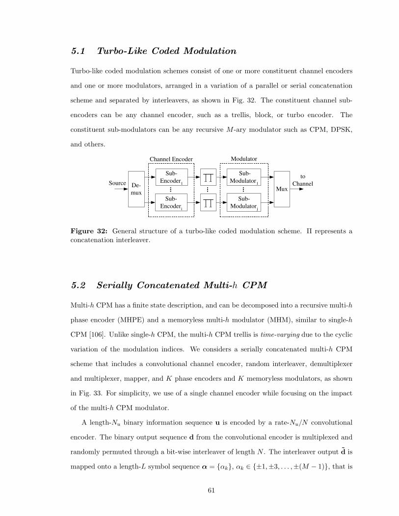
5.1 Turbo-Like Coded Modulation
Turbo-like coded modulation schemes consist of one or more constituent channel encoders
and one or more modulators, arranged in a variation of a parallel or serial concatenation
scheme and separated by interleavers, as shown in Fig. 32. The constituent channel sub-
encoders can be any channel encoder, such as a trellis, block, or turbo encoder. The
constituent sub-modulators can be any recursive M -ary modulator such as CPM, DPSK,
and others.
Channel Encoder Modulator
Sub-
Encoder 1
...
Sub-
Encoder i
De-
mux
Sub-
Modulator 1
Sub-
Modulator j
...
Source to
Channel
...
Mux
Figure 32: General structure of a turbo-like coded modulation scheme. Π represents aconcatenation interleaver.
5.2 Serially Concatenated Multi-h CPM
Multi-h CPM has a finite state description, and can be decomposed into a recursive multi-h
phase encoder (MHPE) and a memoryless multi-h modulator (MHM), similar to single-h
CPM [106]. Unlike single-h CPM, the multi-h CPM trellis is time-varying due to the cyclic
variation of the modulation indices. We considers a serially concatenated multi-h CPM
scheme that includes a convolutional channel encoder, random interleaver, demultiplexer
and multiplexer, mapper, and K phase encoders and K memoryless modulators, as shown
in Fig. 33. For simplicity, we use of a single channel encoder while focusing on the impact
of the multi-h CPM modulator.
A length-Nu binary information sequence u is encoded by a rate-Nu/N convolutional
encoder. The binary output sequence d from the convolutional encoder is multiplexed and
randomly permuted through a bit-wise interleaver of length N . The interleaver output d is
mapped onto a length-L symbol sequence α = {αk}, αk ∈ {±1,±3, . . . ,±(M − 1)}, that is
61
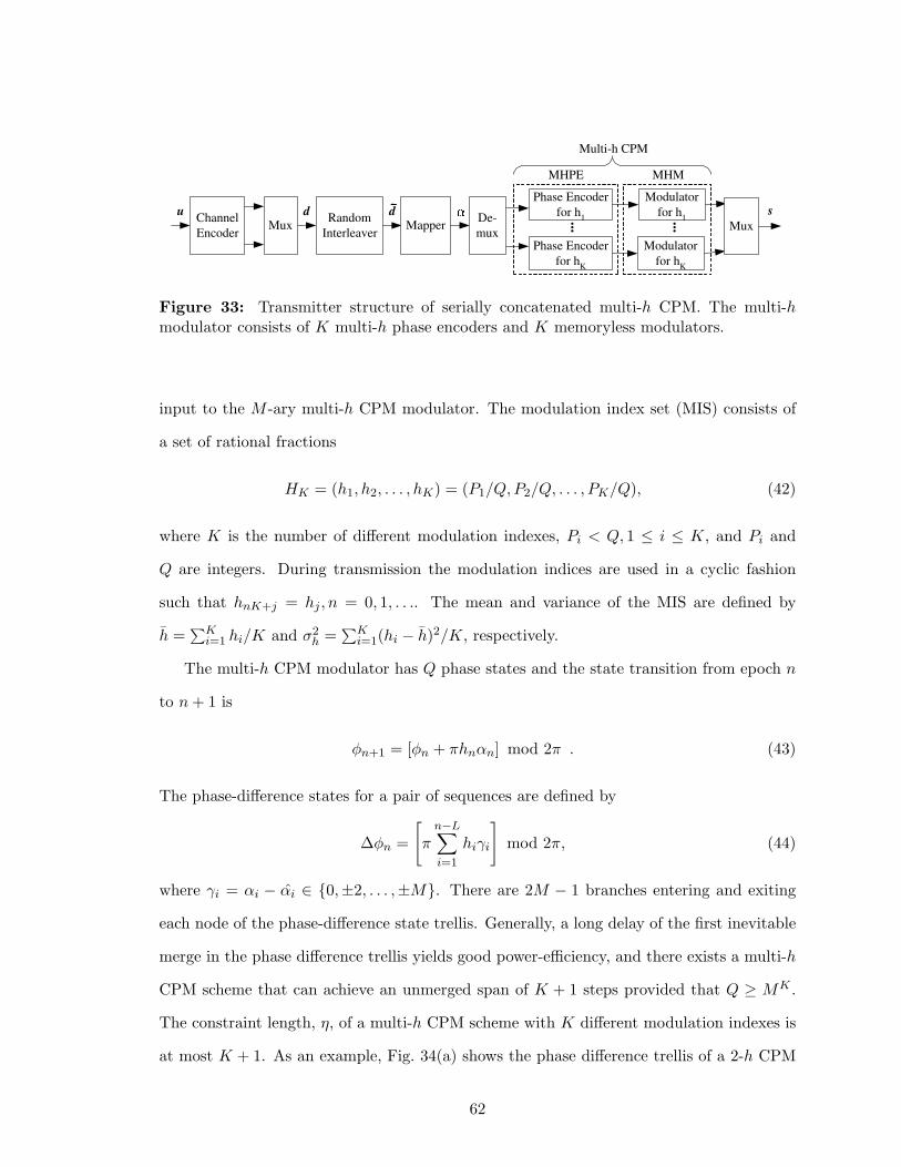
Channel
Encoder
u d Random
Interleaver Mux
s
Multi-h CPM
MHPE
Phase Encoder
for h 1
Phase Encoder
for h K
Modulator
for h 1
Modulator
for h K
...
MHM
De-
mux
... Mux
d Mapper
Figure 33: Transmitter structure of serially concatenated multi-h CPM. The multi-hmodulator consists of K multi-h phase encoders and K memoryless modulators.
input to the M -ary multi-h CPM modulator. The modulation index set (MIS) consists of
a set of rational fractions
HK = (h1, h2, . . . , hK) = (P1/Q, P2/Q, . . . , PK/Q), (42)
where K is the number of different modulation indexes, Pi < Q, 1 ≤ i ≤ K, and Pi and
Q are integers. During transmission the modulation indices are used in a cyclic fashion
such that hnK+j = hj , n = 0, 1, . . .. The mean and variance of the MIS are defined by
h =∑K
i=1 hi/K and σ2h =
∑Ki=1(hi − h)2/K, respectively.
The multi-h CPM modulator has Q phase states and the state transition from epoch n
to n + 1 is
φn+1 = [φn + πhnαn] mod 2π . (43)
The phase-difference states for a pair of sequences are defined by
∆φn =
[
πn−L∑
i=1
hiγi
]
mod 2π, (44)
where γi = αi − αi ∈ {0,±2, . . . ,±M}. There are 2M − 1 branches entering and exiting
each node of the phase-difference state trellis. Generally, a long delay of the first inevitable
merge in the phase difference trellis yields good power-efficiency, and there exists a multi-h
CPM scheme that can achieve an unmerged span of K + 1 steps provided that Q ≥ MK .
The constraint length, η, of a multi-h CPM scheme with K different modulation indexes is
at most K + 1. As an example, Fig. 34(a) shows the phase difference trellis of a 2-h CPM
62
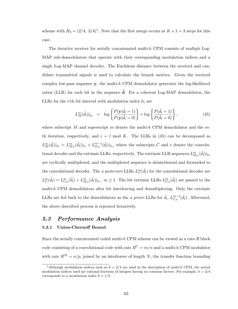
scheme with H2 = (2/4, 3/4)1. Note that the first merge occurs at K +1 = 3 steps for this
case.
The iterative receiver for serially concatenated multi-h CPM consists of multiple Log-
MAP sub-demodulators that operate with their corresponding modulation indices and a
single Log-MAP channel decoder. The Euclidean distance between the received and can-
didate transmitted signals is used to calculate the branch metrics. Given the received
complex low-pass sequence y, the multi-h CPM demodulator generates the log-likelihood
ratios (LLR) for each bit in the sequence d. For a coherent Log-MAP demodulator, the
LLRs for the l-th bit interval with modulation index hi are
LmM (dl)|hi = log
{
P (y|dl = 1)
P (y|dl = 0)
}
+ log
{
P (dl = 1)
P (dl = 0)
}
, (45)
where subscript M and superscript m denote the multi-h CPM demodulator and the m-
th iteration, respectively, and i = l mod K. The LLRs in (45) can be decomposed as
LmM (dl)|hi = Lm
M,e(dl)|hi + Lm−1O,e (dl)|hi , where the subscripts C and e denote the convolu-
tional decoder and the extrinsic LLRs, respectively. The extrinsic LLR sequences LmM,e(dl)|hi
are cyclically multiplexed, and the multiplexed sequence is deinterleaved and forwarded to
the convolutional decoder. The a posteriori LLRs LmC (dl) for the convolutional decoder are
LmC (dl) = Lm
C,e(dl) + LmM,e(dl)|hi , m ≥ 1. The bit extrinsic LLRs Lm
C,e(dl) are passed to the
multi-h CPM demodulators after bit interleaving and demultiplexing. Only the extrinsic
LLRs are fed back to the demodulators as the a priori LLRs for dl, Lm−1C,e (dl). Afterward,
the above described process is repeated iteratively.
5.3 Performance Analysis
5.3.1 Union-Chernoff Bound
Since the serially concatenated coded multi-h CPM scheme can be viewed as a rate-R block
code consisting of a convolutional code with rate RC = m/n and a multi-h CPM modulator
with rate RM = n/p, joined by an interleaver of length N , the transfer function bounding
1Although modulation indices such as h = 2/4 are used in the description of multi-h CPM, the actualmodulation indices used are rational fractions of integers having no common factors. For example, h = 2/4corresponds to a modulation index h = 1/2.
63
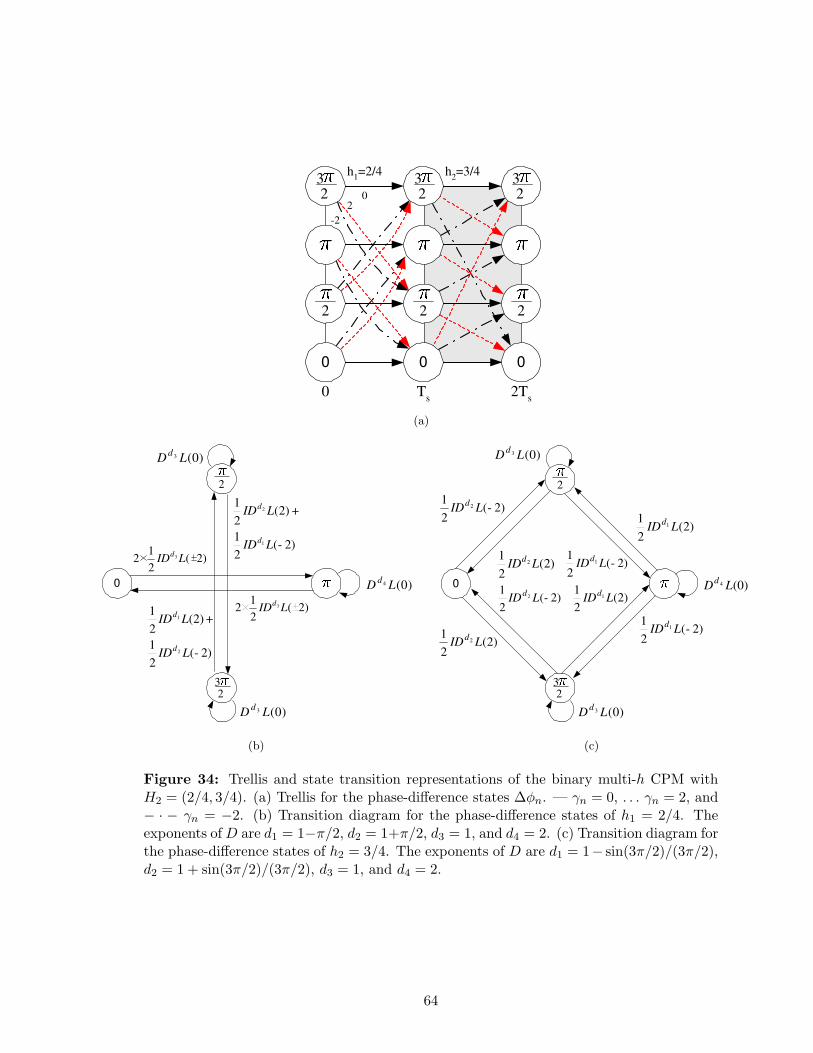
0 T s
2T s
h 2 =3/4
0 2
-2
h 1 =2/4
0
2
2 3
2 3
2 3
2 2
0 0
(a)
0
2
2 3
) 0 ( 3 L D d
) 0 ( 4 L D d
) 2 ( 2
1 2 3 L ID
d ) 2 (
2
1
) 2 ( 2
1
1
2
-
+
L ID
L ID
d
d
) 2 ( 2
1
) 2 ( 2
1
2
1
-
+
L ID
L ID
d
d
) 0 ( 3 L D d
) 2 ( 2
1 2 3 L ID
d
(b)
0
2
2 3
) 2 ( 2
1 2 - L ID
d
) 0 ( 3 L D d
) 2 ( 2
1 2 L ID
d ) 2 (
2
1 1 - L ID
d
) 2 ( 2
1 2 L ID
d
) 2 ( 2
1 1 L ID
d
) 2 ( 2
1 1 - L ID
d
) 2 ( 2
1 1 L ID
d
) 2 ( 2
1 2 - L ID
d
) 0 ( 3 L D d
) 0 ( 4 L D d
(c)
Figure 34: Trellis and state transition representations of the binary multi-h CPM withH2 = (2/4, 3/4). (a) Trellis for the phase-difference states ∆φn. — γn = 0, . . . γn = 2, and− · − γn = −2. (b) Transition diagram for the phase-difference states of h1 = 2/4. Theexponents of D are d1 = 1−π/2, d2 = 1+π/2, d3 = 1, and d4 = 2. (c) Transition diagram forthe phase-difference states of h2 = 3/4. The exponents of D are d1 = 1− sin(3π/2)/(3π/2),d2 = 1 + sin(3π/2)/(3π/2), d3 = 1, and d4 = 2.
64
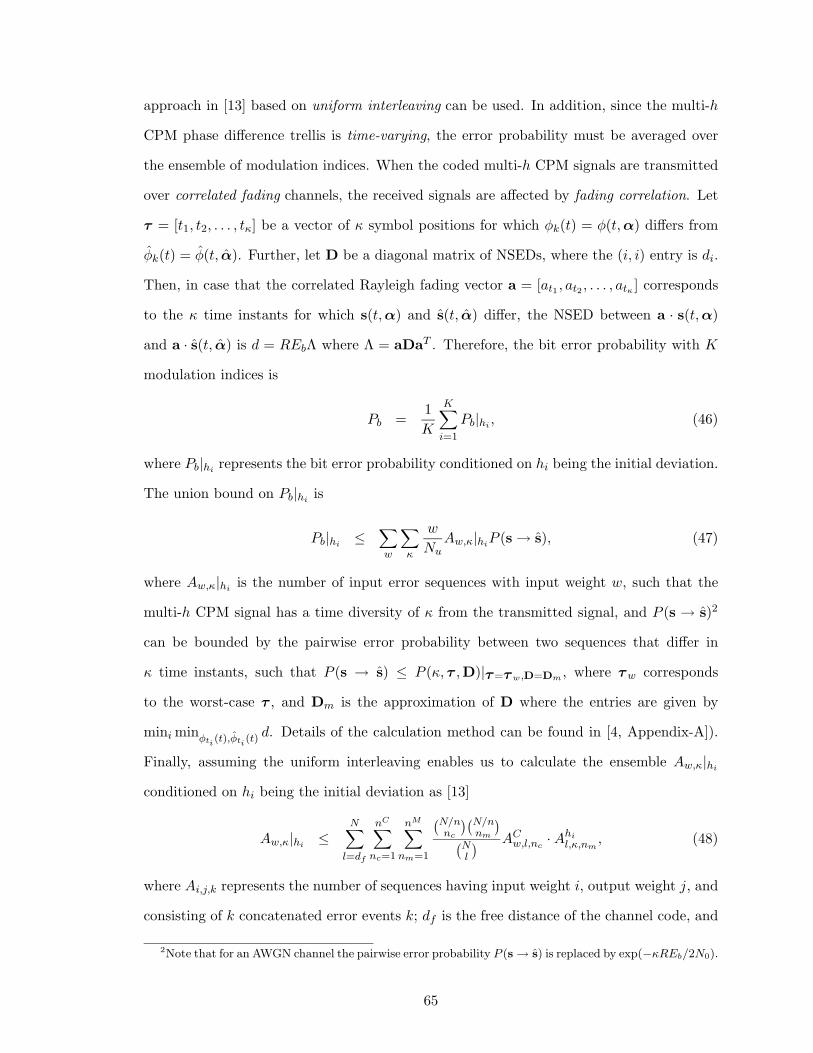
approach in [13] based on uniform interleaving can be used. In addition, since the multi-h
CPM phase difference trellis is time-varying, the error probability must be averaged over
the ensemble of modulation indices. When the coded multi-h CPM signals are transmitted
over correlated fading channels, the received signals are affected by fading correlation. Let
τ = [t1, t2, . . . , tκ] be a vector of κ symbol positions for which φk(t) = φ(t, α) differs from
φk(t) = φ(t, α). Further, let D be a diagonal matrix of NSEDs, where the (i, i) entry is di.
Then, in case that the correlated Rayleigh fading vector a = [at1 , at2 , . . . , atκ ] corresponds
to the κ time instants for which s(t, α) and s(t, α) differ, the NSED between a · s(t, α)
and a · s(t, α) is d = REbΛ where Λ = aDaT . Therefore, the bit error probability with K
modulation indices is
Pb =1
K
K∑
i=1
Pb|hi , (46)
where Pb|hi represents the bit error probability conditioned on hi being the initial deviation.
The union bound on Pb|hi is
Pb|hi ≤∑
w
∑
κ
w
NuAw,κ|hiP (s → s), (47)
where Aw,κ|hi is the number of input error sequences with input weight w, such that the
multi-h CPM signal has a time diversity of κ from the transmitted signal, and P (s → s)2
can be bounded by the pairwise error probability between two sequences that differ in
κ time instants, such that P (s → s) ≤ P (κ, τ ,D)|τ=τ w,D=Dm , where τw corresponds
to the worst-case τ , and Dm is the approximation of D where the entries are given by
mini minφti (t),φti (t)d. Details of the calculation method can be found in [4, Appendix-A]).
Finally, assuming the uniform interleaving enables us to calculate the ensemble Aw,κ|hi
conditioned on hi being the initial deviation as [13]
Aw,κ|hi ≤N∑
l=df
nC∑
nc=1
nM∑
nm=1
(N/nnc
)(N/nnm
)
(Nl
)AC
w,l,nc· Ahi
l,κ,nm, (48)
where Ai,j,k represents the number of sequences having input weight i, output weight j, and
consisting of k concatenated error events k; df is the free distance of the channel code, and
2Note that for an AWGN channel the pairwise error probability P (s → s) is replaced by exp(−κREb/2N0).
65
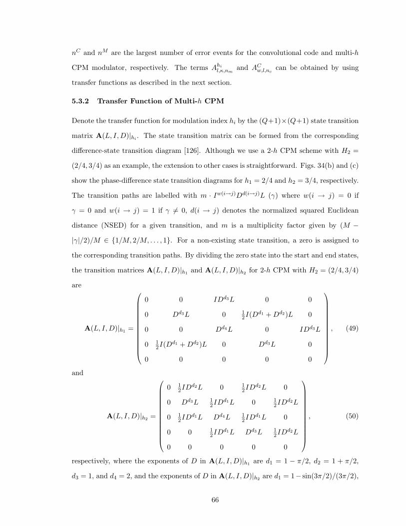
nC and nM are the largest number of error events for the convolutional code and multi-h
CPM modulator, respectively. The terms Ahil,κ,nm
and ACw,l,nc
can be obtained by using
transfer functions as described in the next section.
5.3.2 Transfer Function of Multi-h CPM
Denote the transfer function for modulation index hi by the (Q+1)×(Q+1) state transition
matrix A(L, I, D)|hi . The state transition matrix can be formed from the corresponding
difference-state transition diagram [126]. Although we use a 2-h CPM scheme with H2 =
(2/4, 3/4) as an example, the extension to other cases is straightforward. Figs. 34(b) and (c)
show the phase-difference state transition diagrams for h1 = 2/4 and h2 = 3/4, respectively.
The transition paths are labelled with m · Iw(i→j)Dd(i→j)L (γ) where w(i → j) = 0 if
γ = 0 and w(i → j) = 1 if γ 6= 0, d(i → j) denotes the normalized squared Euclidean
distance (NSED) for a given transition, and m is a multiplicity factor given by (M −
|γ|/2)/M ∈ {1/M, 2/M, . . . , 1}. For a non-existing state transition, a zero is assigned to
the corresponding transition paths. By dividing the zero state into the start and end states,
the transition matrices A(L, I, D)|h1 and A(L, I, D)|h2 for 2-h CPM with H2 = (2/4, 3/4)
are
A(L, I, D)|h1 =
0 0 IDd3L 0 0
0 Dd3L 0 12I(Dd1 + Dd2)L 0
0 0 Dd4L 0 IDd3L
0 12I(Dd1 + Dd2)L 0 Dd3L 0
0 0 0 0 0
, (49)
and
A(L, I, D)|h2 =
0 12IDd2L 0 1
2IDd2L 0
0 Dd3L 12IDd1L 0 1
2IDd2L
0 12IDd1L Dd4L 1
2IDd1L 0
0 0 12IDd1L Dd3L 1
2IDd2L
0 0 0 0 0
, (50)
respectively, where the exponents of D in A(L, I, D)|h1 are d1 = 1 − π/2, d2 = 1 + π/2,
d3 = 1, and d4 = 2, and the exponents of D in A(L, I, D)|h2 are d1 = 1− sin(3π/2)/(3π/2),
66

d2 = 1 + sin(3π/2)/(3π/2), d3 = 1, and d4 = 2.
For binary 2-h CPM schemes, the transfer functions when hi (i = 1, 2) are the initial
deviation corresponding to the upper-right corner entry of AM (L, I, D)|hi , such that
TM (L, I, D)|hi = {AM (L, I, D)|hi}(1,Q+1), (51)
where
AM (L, I, D)|h1 = A|h1 + A|h1A|h2 + A|h1A|h2A|h1 + A|h1A|h2A|h1A|h2 + · · ·
= (I − A|h1A|h2)−1(A|h1 + A|h1A|h2), (52)
where the i-th term in the righthand side of (52) represents a possible state transition at
time iTs, and AM (L, I, D)|h2 can be calculated by exchanging h1 and h2 in (52).
The transfer functions in terms of the input weights and error event lengths are
TM (L, I)|h1 =I2L3(2 − 3L2 + IL − IL2 + I2L + I2L2 + I3L2)
2 − 4L2 + 2L4 − 2IL2 + 2IL4 − I2L4 − I3L4, (53)
and
TM (L, I)|h2 =I2L3(1 + I + IL − IL2 + I2L − 2L2)
2 − 4L2 + 2L4 − 2IL2 + 2IL4 − I2L4 − I3L4. (54)
In (48), Ahil,κ,nm
is the number of error events for the multi-h CPM modulator with the initial
deviation of hi, and is obtained from the transfer function TM (I, L)hi =∑
j
∑
k Ahij,kI
jLk.
Finally, the transfer function of the 4-state non-recursive convolutional encoder with
generator polynomial (7, 5) = (1 + D + D2, 1 + D2) is TC(L, I)(7,5) = IL3
1−IL(1+L) , with free
distance df = 5. In (48), ACw,l,nc
is the number of error events for the convolutional code
and TC(L, I) =∑
w
∑
l ACw,lI
wLl.
5.3.3 Convergence Analysis Based on Input and Output Extrinsic Information
Convergence analysis approache [27] provides an useful framework to evaluate the error
performance in the water-fall region, which shows different behavior from the error-floor
region. The probability density functions p(λ) for input and output extrinsic information for
the iterative multi-h CPM demodulator and decoder is tracked by calculating the histogram
of λ. Assuming a Gaussian and symmetric density approximation, the statistics of p(λ)
67
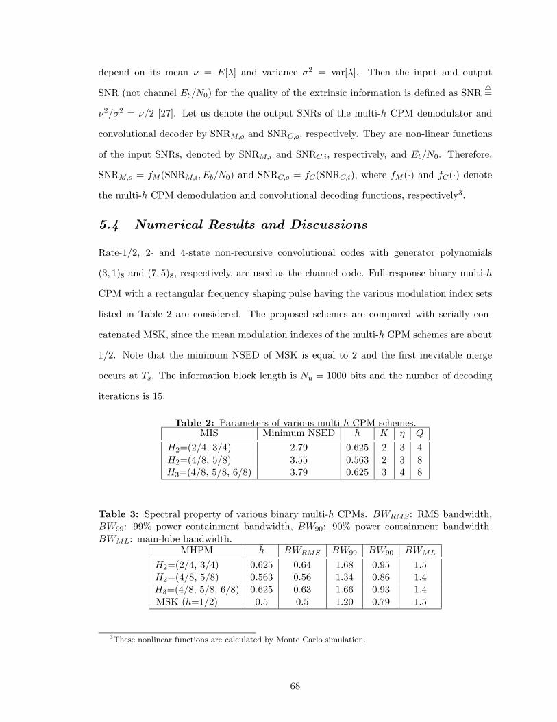
depend on its mean ν = E[λ] and variance σ2 = var[λ]. Then the input and output
SNR (not channel Eb/N0) for the quality of the extrinsic information is defined as SNR△=
ν2/σ2 = ν/2 [27]. Let us denote the output SNRs of the multi-h CPM demodulator and
convolutional decoder by SNRM,o and SNRC,o, respectively. They are non-linear functions
of the input SNRs, denoted by SNRM,i and SNRC,i, respectively, and Eb/N0. Therefore,
SNRM,o = fM (SNRM,i, Eb/N0) and SNRC,o = fC(SNRC,i), where fM (·) and fC(·) denote
the multi-h CPM demodulation and convolutional decoding functions, respectively3.
5.4 Numerical Results and Discussions
Rate-1/2, 2- and 4-state non-recursive convolutional codes with generator polynomials
(3, 1)8 and (7, 5)8, respectively, are used as the channel code. Full-response binary multi-h
CPM with a rectangular frequency shaping pulse having the various modulation index sets
listed in Table 2 are considered. The proposed schemes are compared with serially con-
catenated MSK, since the mean modulation indexes of the multi-h CPM schemes are about
1/2. Note that the minimum NSED of MSK is equal to 2 and the first inevitable merge
occurs at Ts. The information block length is Nu = 1000 bits and the number of decoding
iterations is 15.
Table 2: Parameters of various multi-h CPM schemes.MIS Minimum NSED h K η Q
H2=(2/4, 3/4) 2.79 0.625 2 3 4H2=(4/8, 5/8) 3.55 0.563 2 3 8H3=(4/8, 5/8, 6/8) 3.79 0.625 3 4 8
Table 3: Spectral property of various binary multi-h CPMs. BWRMS : RMS bandwidth,BW99: 99% power containment bandwidth, BW90: 90% power containment bandwidth,BWML: main-lobe bandwidth.
MHPM h BWRMS BW99 BW90 BWML
H2=(2/4, 3/4) 0.625 0.64 1.68 0.95 1.5H2=(4/8, 5/8) 0.563 0.56 1.34 0.86 1.4H3=(4/8, 5/8, 6/8) 0.625 0.63 1.66 0.93 1.4MSK (h=1/2) 0.5 0.5 1.20 0.79 1.5
3These nonlinear functions are calculated by Monte Carlo simulation.
68
5.4.1 Error Performance on AWGN Channels
Fig. 35 shows the bit error rate performance on an AWGN channel. Observe that H2 =
(2/4, 3/4) provides the best performance and outperforms MSK by 0.4 dB. It was reported
in [131] that the spectral properties of H2 = (2/4, 3/4) are very similar to MSK, as sum-
marized in Table 3. Observe also that H2 = (2/4, 3/4) outperforms H2 = (4/8, 5/8) despite
having a smaller minimum NSED and a smaller number of phase states. From Table 2 that
the mean modulation indices of 3-h CPM with H3 = (4/8, 5/8, 6/8) and 2-h CPM with
H2 = (2/4, 3/4) are both equal to 0.625. Surprisingly, 2-h CPM with H2 = (2/4, 3/4) out-
performs 3-h CPM with H3 = (4/8, 5/8, 6/8) despite having a larger minimum NSED. We
conclude that a larger minimum NSED and a larger number of phase states do not necessary
improve the BER performance. Finally, observe that the simpler 2-state convolutional code
outperforms the 4-state convolutional code in the water-fall region despite having a smaller
free distance. However, 2-state code has a lower error-floor than the 4-state code, such that
the former is inferior to the latter at moderate-to-high Eb/N0 region. The above results
will be further explained by convergence analysis.
5.4.2 Convergence Analysis
We assess the effect of the constituent multi-h CPM modulator and convolutional code in the
water-fall region through convergence analysis, as shown in Fig. 36. Fig. 36(a) shows that
the multi-h CPM schemes have a higher initial value of SNRM,o and a steeper slope than
MSK. This explains why the multi-h CPM schemes outperform MSK, as shown in Fig. 35.
Multi-h CPM with H2 = (2/4, 3/4) has a higher initial value of SNRM,o than multi-h CPM
with H3 = (4/8, 5/8, 6/8), resulting in better performance as shown in Fig. 35.
Fig. 36(b) shows the input and output SNR for multi-h CPM with H2 = (2/4, 3/4) at
different Eb/No. Note that the initial value of the upper fM curves when SNRM,i = 0
increases as Eb/No increases. The upper curve for fM and lower curve for f−1C will touch
at Eb/No = γt, where γt represents the minimum Eb/No threshold for convergence in the
iterative demodulation and decoding process. Since γt for the 2-state code is lower than
that for the 4-state code, the 2-state code exhibits superior performance in the water-fall
69
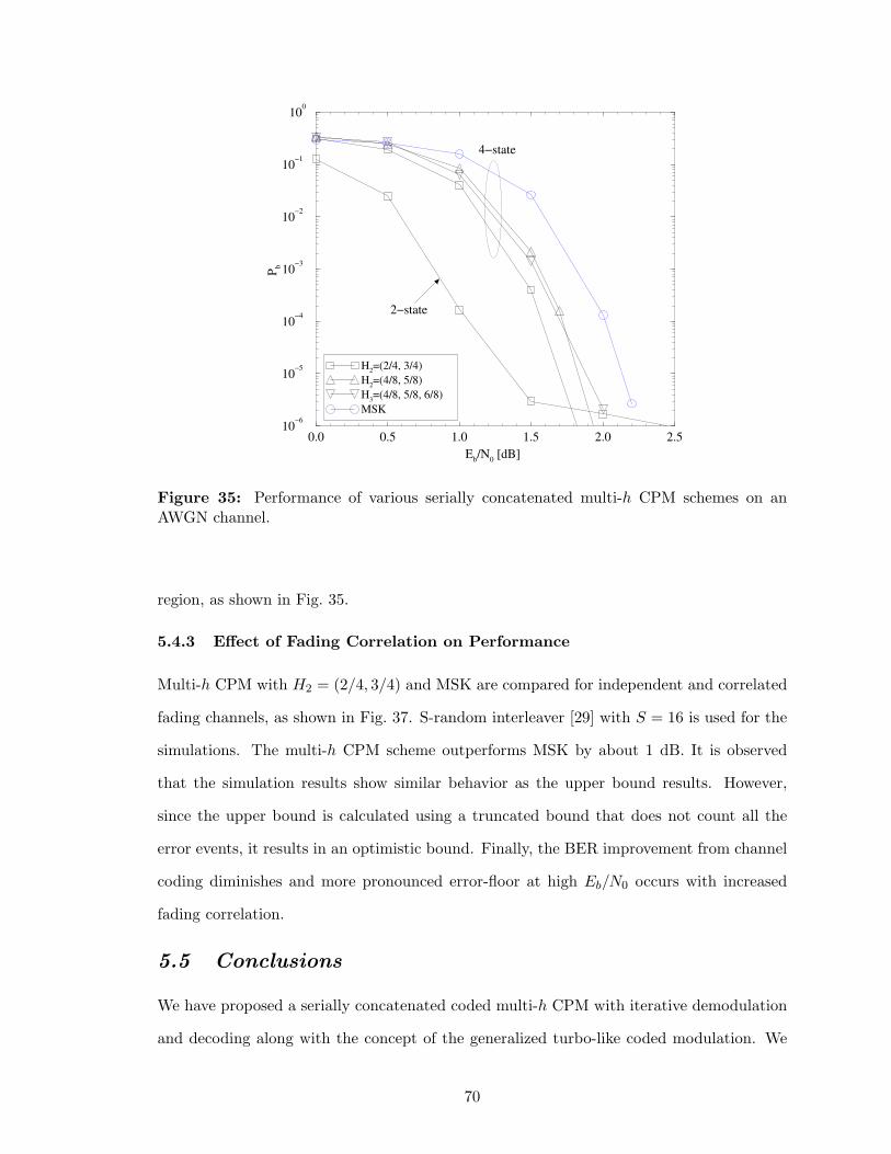
0.0 0.5 1.0 1.5 2.0 2.5
Eb/N
0 [dB]
10−6
10−5
10−4
10−3
10−2
10−1
100
Pb
H2=(2/4, 3/4)
H2=(4/8, 5/8)
H3=(4/8, 5/8, 6/8)
MSK
4−state
2−state
Figure 35: Performance of various serially concatenated multi-h CPM schemes on anAWGN channel.
region, as shown in Fig. 35.
5.4.3 Effect of Fading Correlation on Performance
Multi-h CPM with H2 = (2/4, 3/4) and MSK are compared for independent and correlated
fading channels, as shown in Fig. 37. S-random interleaver [29] with S = 16 is used for the
simulations. The multi-h CPM scheme outperforms MSK by about 1 dB. It is observed
that the simulation results show similar behavior as the upper bound results. However,
since the upper bound is calculated using a truncated bound that does not count all the
error events, it results in an optimistic bound. Finally, the BER improvement from channel
coding diminishes and more pronounced error-floor at high Eb/N0 occurs with increased
fading correlation.
5.5 Conclusions
We have proposed a serially concatenated coded multi-h CPM with iterative demodulation
and decoding along with the concept of the generalized turbo-like coded modulation. We
70
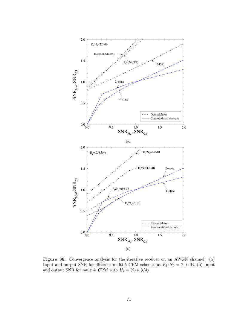
0.0 0.5 1.0 1.5 2.0
SNRM,i
, SNRC,o
0.0
0.5
1.0
1.5
2.0
SN
RM
,o, S
NR
C,i
Demodulator
Convolutional decoder
H3=(4/8,5/8,6/8)
Eb/N
0=2.0 dB
4−state
MSK
2−state
H2=(2/4,3/4)
(a)
0.0 0.5 1.0 1.5 2.0
SNRM,i
, SNRC,o
0.0
0.5
1.0
1.5
2.0
SN
RM
,o, S
NR
C,i
Demodulator
Convolutional decoder
Eb/N
0=0.6 dB
Eb/N
0=1.4 dB
Eb/N
0=2.0 dB
2−state
4−state
Eb/N
0=0 dB
H2=(2/4,3/4)
(b)
Figure 36: Convergence analysis for the iterative receiver on an AWGN channel. (a)Input and output SNR for different multi-h CPM schemes at Eb/N0 = 2.0 dB. (b) Inputand output SNR for multi-h CPM with H2 = (2/4, 3/4).
71
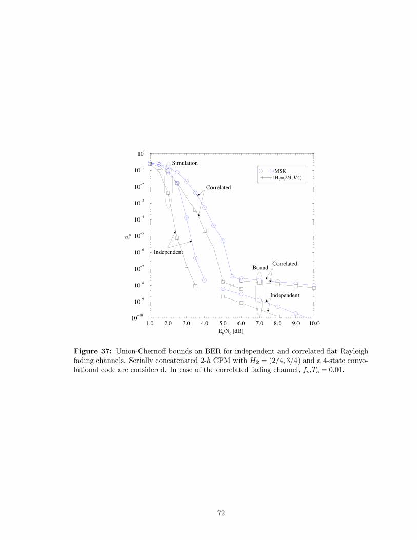
1.0 2.0 3.0 4.0 5.0 6.0 7.0 8.0 9.0 10.0
Eb/N
0 [dB]
10−10
10−9
10−8
10−7
10−6
10−5
10−4
10−3
10−2
10−1
100
Pb
MSK
H2=(2/4,3/4)
Correlated
Independent
Correlated
Independent
Bound
Simulation
Figure 37: Union-Chernoff bounds on BER for independent and correlated flat Rayleighfading channels. Serially concatenated 2-h CPM with H2 = (2/4, 3/4) and a 4-state convo-lutional code are considered. In case of the correlated fading channel, fmTs = 0.01.
72

have shown that a channel code with larger minimum distance, or a multi-h CPM modulator
with a larger number of phase states do not necessary provide better BER performance.
Candidate choices for the modulation index set can be evaluated by using convergence
characteristics and the multi-h modulator should be matched to the channel code. We
have also evaluated performance in the error-floor region through union-Chernoff bounding
techniques.
73

CHAPTER VI
TURBO HYBRID-ARQ FOR W-CDMA
High-quality data transmission through wireless channels becomes a very important require-
ment to support the QoS of various multimedia services. Turbo codes typically operate in
block mode and are, therefore, well suited for packet-data transmission, and have been cho-
sen as one of the channel coding schemes for the 3G IMT-2000 standards [21]. Relatively
long delays due to iterative decoding and retransmission can be tolerated in packet data
transmission.
Generally, FEC coding systems offer good throughput performance, but their reliability
is limited. To overcome the limited reliability of decoded packets, a FEC code can be
combined with an ARQ scheme to form a hybrid-ARQ scheme. The ARQ portion of such a
system provides very high reliability while the FEC portion, by correcting as many erroneous
packets as possible, in advance reduces the frequency of retransmission requests [81]. When
convolutional or block codes are used as a FEC code, various techniques have been suggested
for combining the retransmitted packets to improve the performance. One such technique
is maximum likelihood combining [22], where a maximum likelihood rule is used to combine
the retransmissions. Another technique is code combining or Type-III ARQ [58], where
the code is punctured during one transmission and some or all of the punctured bits are
transmitted during the retransmission.
Recently, several Type-I turbo-coded ARQ (TC-ARQ) schemes by using CRC-based
TC-ARQ [95] and stability-based TC-ARQ [52] schemes for packet-data transmission were
proposed. The TC-ARQ schemes employ multiple encoders, decoders, and interleavers to
diversify retransmission, and utilize the soft-information in case of the iterative decoding
of retransmitted data. At low-to-moderate SNR region, such TC-ARQ schemes can signifi-
cantly decrease the FER.
74
In this chapter, we propose a hybrid-ARQ scheme based on the use of a concatenated RS-
turbo code to provide strong burst-error correction capability as well as low-error probability
by removing the residual errors resulting from a suboptimal turbo decoding. Turbo principle
with a packet combining technique is utilized [65]. The BER and FER performances of
W-CDMA system for multipath fading channels are investigated.
6.1 Concatenated RS-Turbo Coded Hybrid-ARQ
To effectively combat burst errors that occur frequently in wireless channel, a shortened RS
code is concatenated with parallel turbo code. A rate-1/3 turbo code consists of the parallel
concatenation of two convolutional codes with a S-random concatenation interleaver. Each
randomly selected integer is compared to S previously selected integers. If the current
selection is equal to any S previous selections within a distance of ±S, then the current
selection is rejected. This process is repeated until all N integers are selected. While the
searching time increases with S, we can obtain good interleaving pattern in a reasonable
time by choosing S <√
N/2 [29]. The two identical RSC codes are of memory length 3 (i.e.,
8-state), with the code generator polynomials in octal g = (15/13), which is specified in the
cdma2000 standard [123]. Iterative decoding with Max-Log-MAP SISO decoders is used
for its fast decoding and easy implementation due to low complexity [50], [107]. If a proper
scaling of the signal prior to quantization is performed, a negligible degradation of the error
performance can be incurred with 8-bit quantization compared to that of floating point
calculation. Thus, the demodulated signal output is quantized. The fixed point decoding
algorithm that is needed in a real-time turbo decoder can avoid destructive overflow problem
[134].
For the Simple turbo-coded ARQ in [95], the transmitter sends the same packet dur-
ing every retransmission until the packet is deemed to be correctly decoded. The receiver
ignores previous transmissions, and decodes the received sequence for each transmission in-
dependently. Clearly, this scheme is simple but inferior. The performance of this scheme can
be enhanced significantly with a minimal increase in complexity and storage requirements.
In the following, the turbo hybrid-ARQ with average packet combining (APC) will be
75
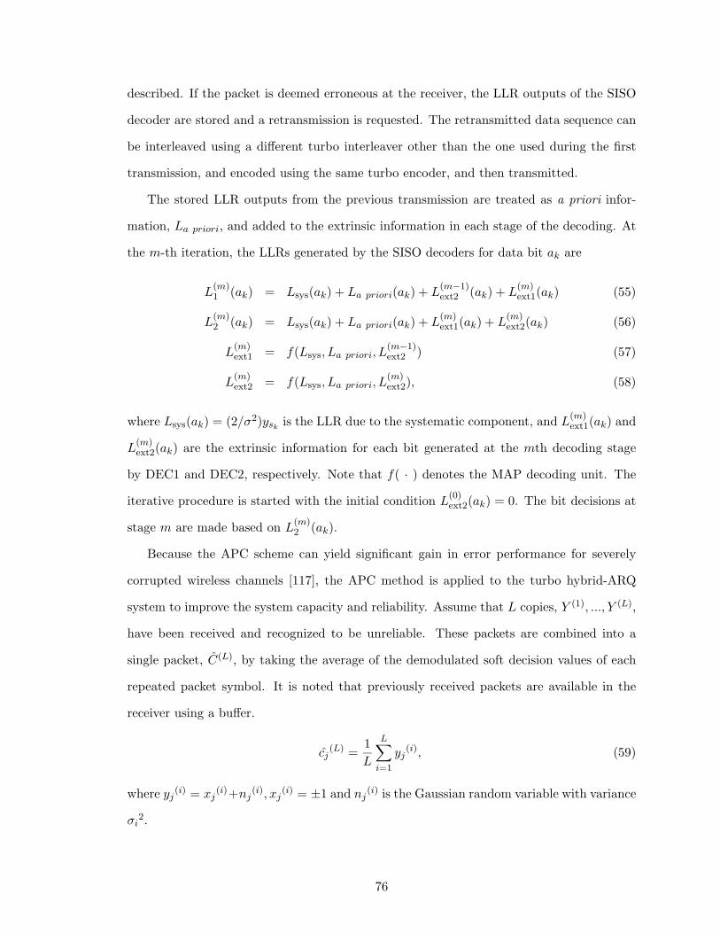
described. If the packet is deemed erroneous at the receiver, the LLR outputs of the SISO
decoder are stored and a retransmission is requested. The retransmitted data sequence can
be interleaved using a different turbo interleaver other than the one used during the first
transmission, and encoded using the same turbo encoder, and then transmitted.
The stored LLR outputs from the previous transmission are treated as a priori infor-
mation, La priori, and added to the extrinsic information in each stage of the decoding. At
the m-th iteration, the LLRs generated by the SISO decoders for data bit ak are
L(m)1 (ak) = Lsys(ak) + La priori(ak) + L
(m−1)ext2 (ak) + L
(m)ext1(ak) (55)
L(m)2 (ak) = Lsys(ak) + La priori(ak) + L
(m)ext1(ak) + L
(m)ext2(ak) (56)
L(m)ext1 = f(Lsys, La priori, L
(m−1)ext2 ) (57)
L(m)ext2 = f(Lsys, La priori, L
(m)ext2), (58)
where Lsys(ak) = (2/σ2)yskis the LLR due to the systematic component, and L
(m)ext1(ak) and
L(m)ext2(ak) are the extrinsic information for each bit generated at the mth decoding stage
by DEC1 and DEC2, respectively. Note that f( · ) denotes the MAP decoding unit. The
iterative procedure is started with the initial condition L(0)ext2(ak) = 0. The bit decisions at
stage m are made based on L(m)2 (ak).
Because the APC scheme can yield significant gain in error performance for severely
corrupted wireless channels [117], the APC method is applied to the turbo hybrid-ARQ
system to improve the system capacity and reliability. Assume that L copies, Y (1), ..., Y (L),
have been received and recognized to be unreliable. These packets are combined into a
single packet, C(L), by taking the average of the demodulated soft decision values of each
repeated packet symbol. It is noted that previously received packets are available in the
receiver using a buffer.
cj(L) =
1
L
L∑
i=1
yj(i), (59)
where yj(i) = xj
(i)+nj(i), xj
(i) = ±1 and nj(i) is the Gaussian random variable with variance
σi2.
76

Since the additional interleaver in turbo hybrid-ARQ encoder acts as an additional chan-
nel interleaver and the turbo encoder structure has to be modified whenever retransmission
is requested, it causes more complexity and delay from additional encoding and interleav-
ing. Therefore, we can remove the additional interleaver except for the turbo interleaver.
The stored SISO LLR output, Lp(u), from the previous transmission is compared with the
deinterleaved LLR of the extrinsic information, L2(u; O), from the second SISO decoder
(SISO DEC2). If the absolute value of the deinterleaved LLR is less than absolute value of
Lp(u), |Lp(u)|, then Lp(u) is added to the extrinsic information to form more reliable LLR,
L1(u; I) at the next iteration. During the initial iteration stage, Lp(u) is used instead of
initial zero value. Note that since the addition of Lp(u) at medium-to-low SNR region is a
little constructive, it is not necessary to add it. The turbo hybrid-ARQ decoder is shown
in Fig. 38.
SISO
DEC1
SISO
DEC2 INT
DEINT
DEINT
L 1 (c;I)
L 1 (u;I)
L 2 (c;I)
Soft
Output
Hard
Output
u
L 1 (c;O)
L 1 (u;O) L
2 (u;I)
L 2 (c;O)
L 2 (u;O)
L p (u)
LLR
Compare & Add
Figure 38: The structure of the turbo hybrid-ARQ decoder.
6.2 W-CDMA System with Turbo Hybrid-ARQ
6.2.1 System Description
W-CDMA has been proposed as a promising 3G multiple access scheme for the IMT-2000
[21] systems because it can support large capacity and high data rate transmission [2].
Turbo coding also provides an adaptive and reliable mobile multimedia data transmission,
especially delay tolerant packet transmission [91]. In many cases, CDMA is supported by
77
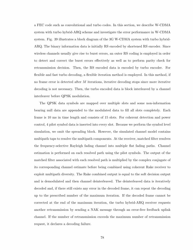
a FEC code such as convolutional and turbo codes. In this section, we describe W-CDMA
system with turbo hybrid-ARQ scheme and investigate the error performance in W-CDMA
system. Fig. 39 illustrates a block diagram of the 3G W-CDMA system with turbo hybrid-
ARQ. The binary information data is initially RS encoded by shortened RS encoder. Since
wireless channels usually give rise to burst errors, an outer RS coding is employed in order
to detect and correct the burst errors effectively as well as to perform parity check for
retransmission decision. Then, the RS encoded data is encoded by turbo encoder. For
flexible and fast turbo decoding, a flexible iteration method is employed. In this method, if
no frame error is detected after M iterations, iterative decoding stops since more iterative
decoding is not necessary. Then, the turbo encoded data is block interleaved by a channel
interleaver before QPSK modulation.
The QPSK data symbols are mapped over multiple slots and some non-information
bearing null data are appended to the modulated data to fill all slots completely. Each
frame is 10 ms in time length and consists of 15 slots. For coherent detection and power
control, 4 pilot symbol data is inserted into every slot. Because we perform the symbol level
simulation, we omit the spreading block. However, the simulated channel model contains
multipath taps to resolve the multipath components. At the receiver, matched filter resolves
the frequency-selective Rayleigh fading channel into multiple flat fading paths. Channel
estimation is performed on each resolved path using the pilot symbols. The output of the
matched filter associated with each resolved path is multiplied by the complex conjugate of
its corresponding channel estimate before being combined using coherent Rake receiver to
exploit multipath diversity. The Rake combined output is equal to the soft decision output
and is demodulated and then channel deinterleaved. The deinterleaved data is iteratively
decoded and, if there still exists any error in the decoded frame, it can repeat the decoding
up to the prescribed number of the maximum iteration. If the decoded frame cannot be
corrected at the end of the maximum iteration, the turbo hybrid-ARQ receiver requests
another retransmission by sending a NAK message through an error-free feedback uplink
channel. If the number of retransmission exceeds the maximum number of retransmission
request, it declares a decoding failure.
78
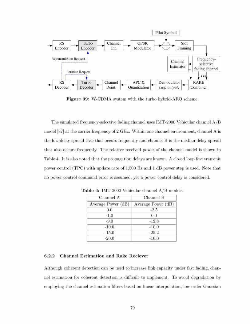
Frequency-
selective
fading channel
Turbo
Encoder
Turbo
Decoder
Channel
Int.
Channel
Deint.
Turbo
Encoder
QPSK
Modulator
Demodulator
(soft output)
Pilot Symbol
...
Slot
Framing
RAKE
Combiner
Channel
Estimator
RS
Encoder
Retransmission Request
Iteration Request
RS
Decoder
APC &
Quantization
Figure 39: W-CDMA system with the turbo hybrid-ARQ scheme.
The simulated frequency-selective fading channel uses IMT-2000 Vehicular channel A/B
model [87] at the carrier frequency of 2 GHz. Within one channel environment, channel A is
the low delay spread case that occurs frequently and channel B is the median delay spread
that also occurs frequently. The relative received power of the channel model is shown in
Table 4. It is also noted that the propagation delays are known. A closed loop fast transmit
power control (TPC) with update rate of 1,500 Hz and 1 dB power step is used. Note that
no power control command error is assumed, yet a power control delay is considered.
Table 4: IMT-2000 Vehicular channel A/B models.
Channel A Channel B
Average Power (dB) Average Power (dB)
0.0 -2.5
-1.0 0.0
-9.0 -12.8
-10.0 -10.0
-15.0 -25.2
-20.0 -16.0
6.2.2 Channel Estimation and Rake Reciever
Although coherent detection can be used to increase link capacity under fast fading, chan-
nel estimation for coherent detection is difficult to implement. To avoid degradation by
employing the channel estimation filters based on linear interpolation, low-order Gaussian
79
interpolation, Wiener filtering, and pilot symbol-assisted coherent orthogonal filtering [6],
a channel estimation technique using time-multiplexed pilot symbols that operates well
throughout the range of slow-to-fast fading was proposed for 3G W-CDMA system. The
pilot symbols that are inserted at the beginning of each slot are periodically multiplexed
with the sequence of transmitted data, and the pilot symbols and data symbols following
pilot symbols constitute a slot as shown in Fig. 40 (a). The used channel estimation filter
is called the weighted multi-slot averaging (WMSA) channel estimation filter because it
uses pilot symbols throughout multiple slots. It was shown that the performance for the
time-multiplexed pilot channel is slightly better than that of the parallel pilot channel [6].
In this section, we investigate channel estimation technique based on WMSA filters in [6],
and simulate the error performance.
The binary information data for a user to be transmitted is turbo-encoded. The turbo
encoded data is block interleaved by a channel interleaver before QPSK modulation. The
QPSK data symbols are mapped over multiple slots and non-information bearing null data
are appended as necessary to the modulated data to fill all slots completely. Each frame
is 10 ms, Tframe, in duration and consists of 15 slots (i.e., Tslot = 10 ms/15 ≈ 0.667 ms)
with symbol period of Ts = Tslot(Nd+Np) where Np and Nd are denoted as the number of pilot
and data symbols in each slot, respectively. For coherent detection and fast TPC, known
unmodulated 4 pilot symbols are inserted into at the beginning of every slot as shown in
Fig. 40 (a). Namely, pilot symbols and data symbols are time-multiplexed in each slot.
Note that Fig. 40 (b) illustrates the frame structure using an alternative parallel pilot
channel. Because we perform symbol level simulation for simplicity, the chip-spreading
block is omitted.
The k-th user’s turbo-encoded data signal bk(t) is modulated onto the phase-coded
carrier ck(t), which is given by
ck(t) =√
2Pak(t)e(ωct+θk), (60)
where P , θk, and ωc = 2πfc stand for common signal power, the phase of the k-th carrier,
and the center frequency, respectively, and ak(t) represents spreading sequence which is
80
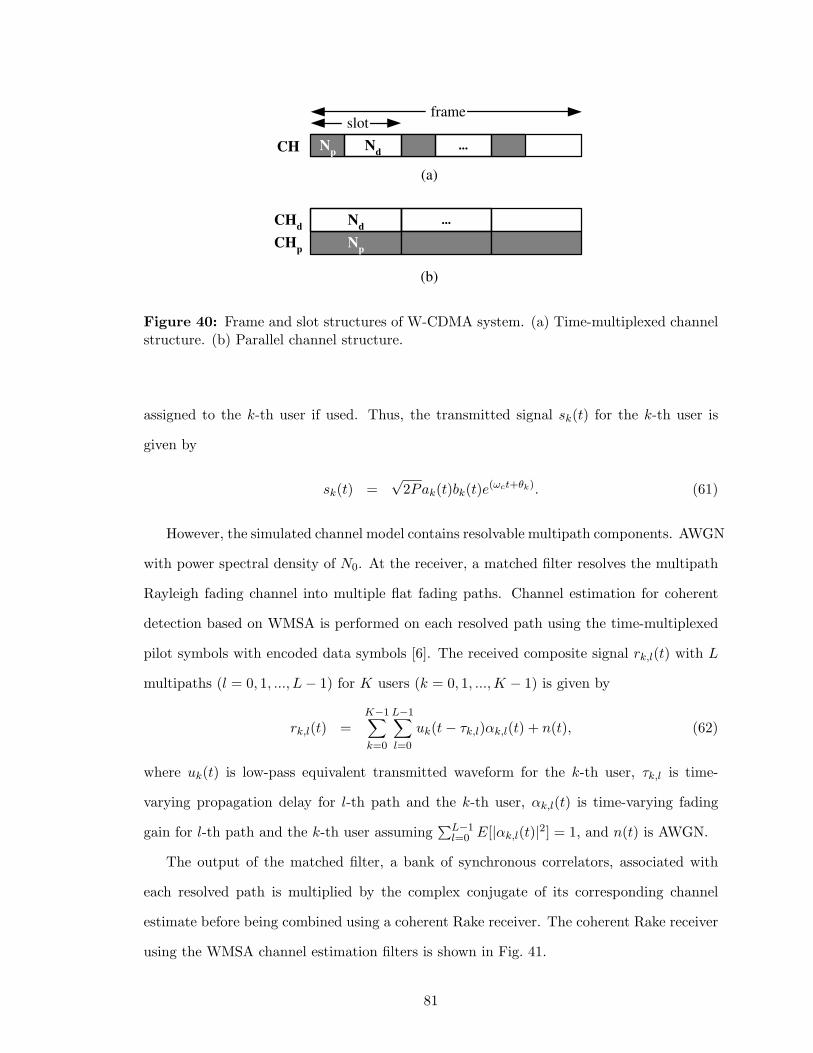
N p
frame slot
N d
...
(b)
N p
N d
...
CH
CH d
CH p
(a)
Figure 40: Frame and slot structures of W-CDMA system. (a) Time-multiplexed channelstructure. (b) Parallel channel structure.
assigned to the k-th user if used. Thus, the transmitted signal sk(t) for the k-th user is
given by
sk(t) =√
2Pak(t)bk(t)e(ωct+θk). (61)
However, the simulated channel model contains resolvable multipath components. AWGN
with power spectral density of N0. At the receiver, a matched filter resolves the multipath
Rayleigh fading channel into multiple flat fading paths. Channel estimation for coherent
detection based on WMSA is performed on each resolved path using the time-multiplexed
pilot symbols with encoded data symbols [6]. The received composite signal rk,l(t) with L
multipaths (l = 0, 1, ..., L − 1) for K users (k = 0, 1, ..., K − 1) is given by
rk,l(t) =K−1∑
k=0
L−1∑
l=0
uk(t − τk,l)αk,l(t) + n(t), (62)
where uk(t) is low-pass equivalent transmitted waveform for the k-th user, τk,l is time-
varying propagation delay for l-th path and the k-th user, αk,l(t) is time-varying fading
gain for l-th path and the k-th user assuming∑L−1
l=0 E[|αk,l(t)|2] = 1, and n(t) is AWGN.
The output of the matched filter, a bank of synchronous correlators, associated with
each resolved path is multiplied by the complex conjugate of its corresponding channel
estimate before being combined using a coherent Rake receiver. The coherent Rake receiver
using the WMSA channel estimation filters is shown in Fig. 41.
81
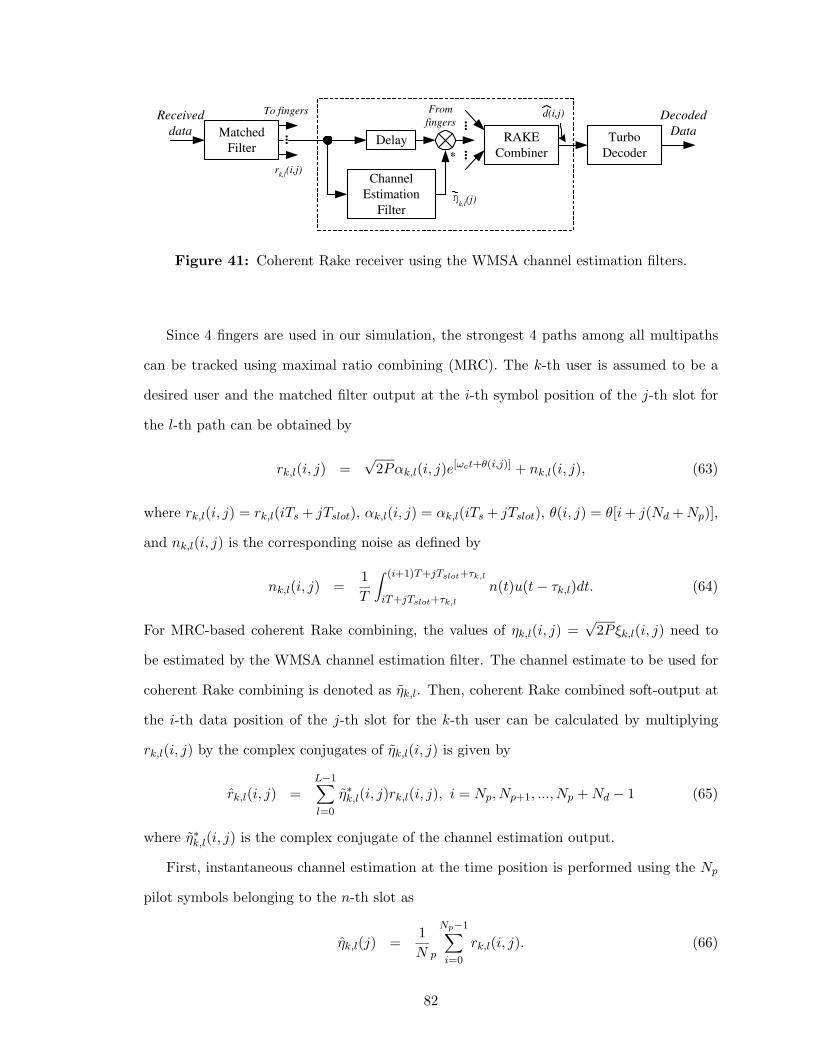
Matched
Filter Delay
Channel
Estimation
Filter
Turbo
Decoder
Received
data
...
...
...
To fingers From
fingers
r k,l
(i,j)
RAKE
Combiner
d (i,j)
*
Decoded
Data
k,l (j)
Figure 41: Coherent Rake receiver using the WMSA channel estimation filters.
Since 4 fingers are used in our simulation, the strongest 4 paths among all multipaths
can be tracked using maximal ratio combining (MRC). The k-th user is assumed to be a
desired user and the matched filter output at the i-th symbol position of the j-th slot for
the l-th path can be obtained by
rk,l(i, j) =√
2Pαk,l(i, j)e[ωct+θ(i,j)] + nk,l(i, j), (63)
where rk,l(i, j) = rk,l(iTs + jTslot), αk,l(i, j) = αk,l(iTs + jTslot), θ(i, j) = θ[i + j(Nd + Np)],
and nk,l(i, j) is the corresponding noise as defined by
nk,l(i, j) =1
T
∫ (i+1)T+jTslot+τk,l
iT+jTslot+τk,l
n(t)u(t − τk,l)dt. (64)
For MRC-based coherent Rake combining, the values of ηk,l(i, j) =√
2Pξk,l(i, j) need to
be estimated by the WMSA channel estimation filter. The channel estimate to be used for
coherent Rake combining is denoted as ηk,l. Then, coherent Rake combined soft-output at
the i-th data position of the j-th slot for the k-th user can be calculated by multiplying
rk,l(i, j) by the complex conjugates of ηk,l(i, j) is given by
rk,l(i, j) =L−1∑
l=0
η∗k,l(i, j)rk,l(i, j), i = Np, Np+1, ..., Np + Nd − 1 (65)
where η∗k,l(i, j) is the complex conjugate of the channel estimation output.
First, instantaneous channel estimation at the time position is performed using the Np
pilot symbols belonging to the n-th slot as
ηk,l(j) =1
N p
Np−1∑
i=0
rk,l(i, j). (66)
82

The fading variation over the interval of Np pilot symbols is negligible, so ηk,l(j) is
approximated to
ηk,l(j) ≈√
2Pξk,l(i = 0, j) + nk,l(j), (67)
where nk,l(j) is a complex-valued Gaussian noise with variance of (N0/T )/Np. Therefore,
the SNR of the channel estimate increases Np times from the received SNR per symbol. In
the case of slow fading, the channel gain remains almost the same over a period of several
slots, so we can coherently add the several consecutive channel estimates in order to extend
the observation interval. We apply a linear filter having 2M taps to extend the observation
period to 2M slots. The filter output is expressed as
ηk,l(j) =M−1∑
i=0
βiηk,l(j − i) +M∑
i=0
βi−1ηk,l(j + i), (68)
where βi is the real-valued weighting factor (or linear filter tap coefficient). The filter output
ηk,l(j) is used as the channel estimate at all time positions of the n-th slot, so the channel
estimate ηk,l(i, j) is reduced to ηk,l(j) where i = Np, Np+1, ..., Np + Nd − 1. The weighting
factor βi’s are summarized in Table 5.
Table 5: Weighting factors for the WMSA channel estimation.
Number of slots (M) Weighting factors (β)
6 β0 = 1, β1 = 0.8, β2 = 0.3
4 β0 = 1, β1 = 0.6
By using larger number of multiple slots and by selecting the appropriate weighting
factors βi’s, more accurate channel estimation is achieved. If the fading is very slow, the
2M -tap WMSA channel estimator increases the SNR of the channel estimate by a factor of
γ which is defined by
γ = Np
(
∑M−1i=0 βi
)2
∑M−1i=0 β2
i
. (69)
Although we consider a single user case (K = 0) in this work, multiple access interference
(MAI) can be approximated as Gaussian noise for a large number of users. Thus, results
can be extended to a multiuser environment by substituting N0 with N0 + I0, where N0
and I0 represents the variances of Gaussian noise and MAI, respectively.
83
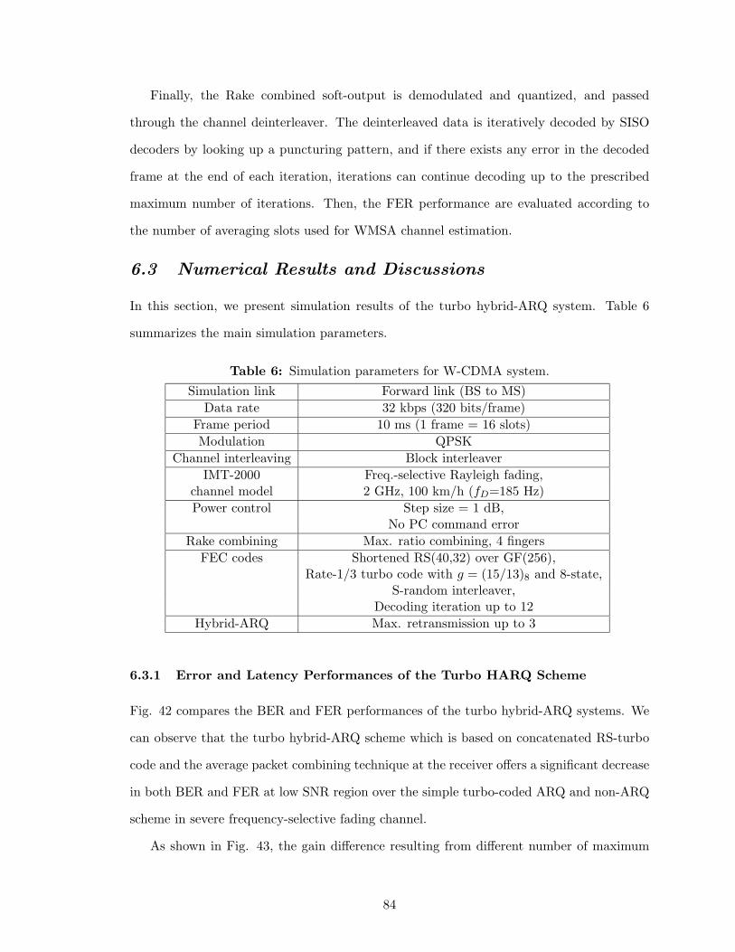
Finally, the Rake combined soft-output is demodulated and quantized, and passed
through the channel deinterleaver. The deinterleaved data is iteratively decoded by SISO
decoders by looking up a puncturing pattern, and if there exists any error in the decoded
frame at the end of each iteration, iterations can continue decoding up to the prescribed
maximum number of iterations. Then, the FER performance are evaluated according to
the number of averaging slots used for WMSA channel estimation.
6.3 Numerical Results and Discussions
In this section, we present simulation results of the turbo hybrid-ARQ system. Table 6
summarizes the main simulation parameters.
Table 6: Simulation parameters for W-CDMA system.
Simulation link Forward link (BS to MS)
Data rate 32 kbps (320 bits/frame)
Frame period 10 ms (1 frame = 16 slots)
Modulation QPSK
Channel interleaving Block interleaver
IMT-2000 Freq.-selective Rayleigh fading,channel model 2 GHz, 100 km/h (fD=185 Hz)
Power control Step size = 1 dB,No PC command error
Rake combining Max. ratio combining, 4 fingers
FEC codes Shortened RS(40,32) over GF(256),Rate-1/3 turbo code with g = (15/13)8 and 8-state,
S-random interleaver,Decoding iteration up to 12
Hybrid-ARQ Max. retransmission up to 3
6.3.1 Error and Latency Performances of the Turbo HARQ Scheme
Fig. 42 compares the BER and FER performances of the turbo hybrid-ARQ systems. We
can observe that the turbo hybrid-ARQ scheme which is based on concatenated RS-turbo
code and the average packet combining technique at the receiver offers a significant decrease
in both BER and FER at low SNR region over the simple turbo-coded ARQ and non-ARQ
scheme in severe frequency-selective fading channel.
As shown in Fig. 43, the gain difference resulting from different number of maximum
84
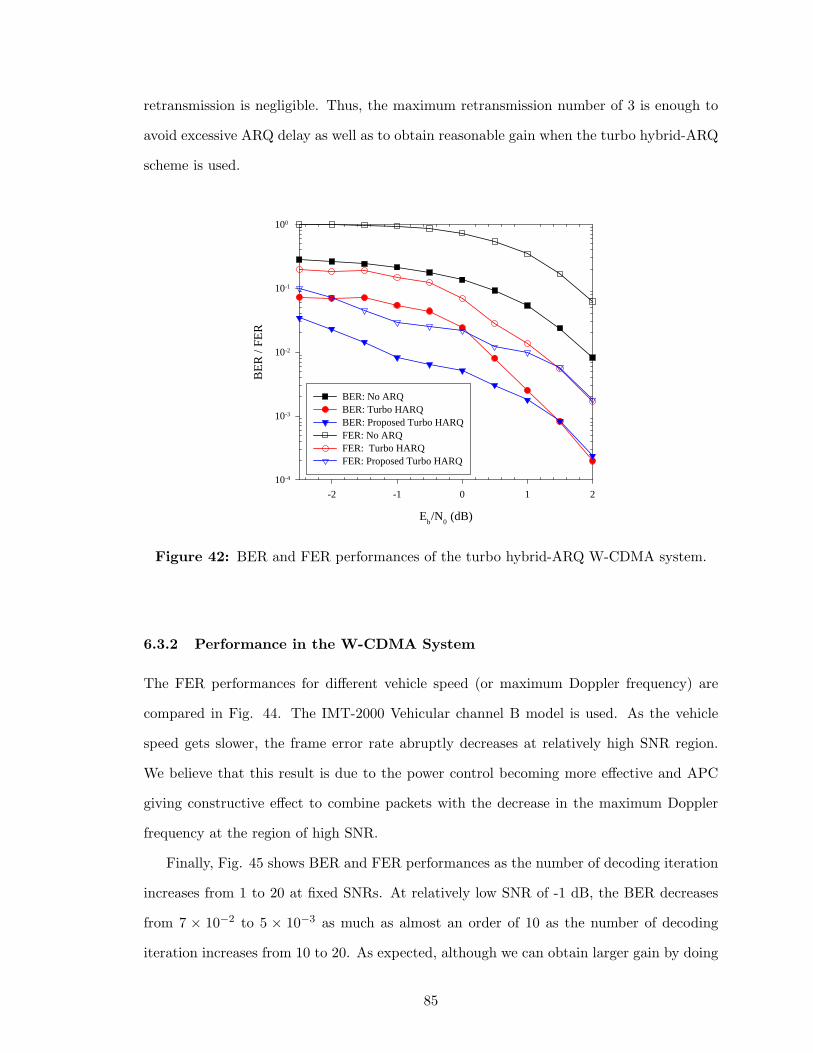
retransmission is negligible. Thus, the maximum retransmission number of 3 is enough to
avoid excessive ARQ delay as well as to obtain reasonable gain when the turbo hybrid-ARQ
scheme is used.
Eb/N
0 (dB)
-2 -1 0 1 2
BE
R /
FER
10-4
10-3
10-2
10-1
100
BER: No ARQBER: Turbo HARQBER: Proposed Turbo HARQFER: No ARQFER: Turbo HARQFER: Proposed Turbo HARQ
Figure 42: BER and FER performances of the turbo hybrid-ARQ W-CDMA system.
6.3.2 Performance in the W-CDMA System
The FER performances for different vehicle speed (or maximum Doppler frequency) are
compared in Fig. 44. The IMT-2000 Vehicular channel B model is used. As the vehicle
speed gets slower, the frame error rate abruptly decreases at relatively high SNR region.
We believe that this result is due to the power control becoming more effective and APC
giving constructive effect to combine packets with the decrease in the maximum Doppler
frequency at the region of high SNR.
Finally, Fig. 45 shows BER and FER performances as the number of decoding iteration
increases from 1 to 20 at fixed SNRs. At relatively low SNR of -1 dB, the BER decreases
from 7 × 10⁻² to 5 × 10⁻³ as much as almost an order of 10 as the number of decoding
iteration increases from 10 to 20. As expected, although we can obtain larger gain by doing
85
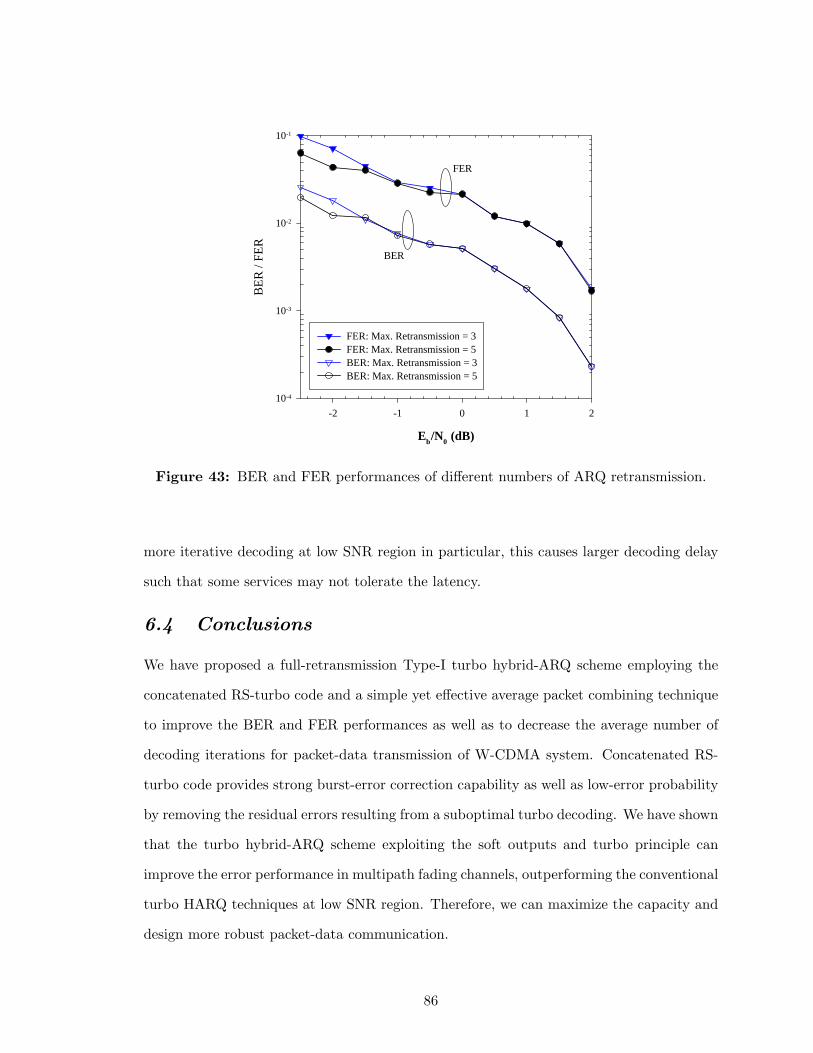
Eb/N0 (dB)
-2 -1 0 1 2
BE
R /
FER
10-4
10-3
10-2
10-1
FER: Max. Retransmission = 3FER: Max. Retransmission = 5BER: Max. Retransmission = 3BER: Max. Retransmission = 5
FER
BER
Figure 43: BER and FER performances of different numbers of ARQ retransmission.
more iterative decoding at low SNR region in particular, this causes larger decoding delay
such that some services may not tolerate the latency.
6.4 Conclusions
We have proposed a full-retransmission Type-I turbo hybrid-ARQ scheme employing the
concatenated RS-turbo code and a simple yet effective average packet combining technique
to improve the BER and FER performances as well as to decrease the average number of
decoding iterations for packet-data transmission of W-CDMA system. Concatenated RS-
turbo code provides strong burst-error correction capability as well as low-error probability
by removing the residual errors resulting from a suboptimal turbo decoding. We have shown
that the turbo hybrid-ARQ scheme exploiting the soft outputs and turbo principle can
improve the error performance in multipath fading channels, outperforming the conventional
turbo HARQ techniques at low SNR region. Therefore, we can maximize the capacity and
design more robust packet-data communication.
86
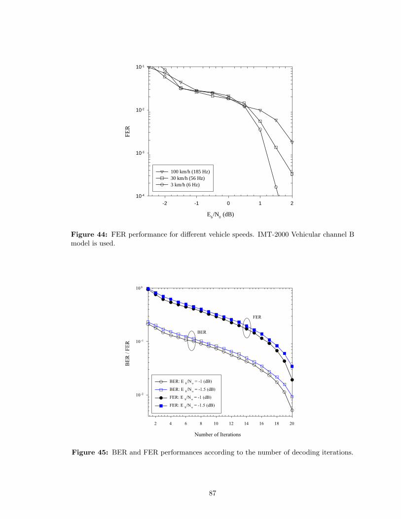
Eb/N
0 (dB)
-2 -1 0 1 2
FER
10-4
10-3
10-2
10-1
100 km/h (185 Hz)30 km/h (56 Hz)3 km/h (6 Hz)
Figure 44: FER performance for different vehicle speeds. IMT-2000 Vehicular channel Bmodel is used.
Figure 45: BER and FER performances according to the number of decoding iterations.
87
CHAPTER VII
RATE COMPATIBLE PUNCTURED TURBO-LIKE
CODES
In this chapter, we propose rate compatible punctured turbo-like codes using PCCC and
SCCC and their puncturing methods to support adaptive code rate and incremental redun-
dancy retransmission for packet-data networks. In addition, we propose Type-II RCPT-
HARQ and RCPS-HARQ schemes that provide excellent performance in reliability and
throughput.
7.1 Rate Compatible Punctured Turbo Codes
FEC codes such as convolutional and turbo codes generally require the selection of a fixed
coding rate that is well adapted to the channel characteristics. However, in some cases,
a more adaptive and versatile coding scheme is needed to meet unequal error protection
requirements or/and to cope with unknown or time varying channel conditions. Rate com-
patible punctured turbo codes can meet these needs. Motivated by the RCPC codes, RCPT
codes with code rates of 1/3 and 1/2 were introduced in [10] and the performance of the
RCPT codes on AWGN and flat Rayleigh fading channels was discussed in [57].
The FER performance of turbo-like codes usually improves with the increase in the
block length due to the beneficial interleaving gain in contrast to the convolutional codes.
Therefore, it is promising to use turbo-like codes to transmit a non-real time long packet-
data. Furthermore, by employing a rate compatible punctured turbo hybrid-ARQ (RCPT-
HARQ) protocol, we can achieve a more reliable packet-data transmission scheme. However,
we need to select and adjust the puncturing patterns, incremental step, and repetition
number according to the given service requirements and channel conditions. Recently, the
use of RCPT codes in a HARQ system on a non-stationary Gaussian channel was proposed
in [109]. In [76], rate compatible turbo codes were applied to a Type-II HARQ system
88
to obtain high reliability and throughput performance at low SNR region. As a practical
application, an adaptive packet soft handoff scheme using punctured turbo coding was
proposed in [63].
Since RCPT coding provides excellent unequal-error protection, which means rate vari-
ation within a packet is possible due to the code compatibility, and rate adaptation capabil-
ities to a time-varying fading channel, we can easily achieve a good throughput performance
without increasing the system complexity and block length. Since RCPT coding requires a
single rate-1/n turbo encoder and iterative decoder pair, and the transmitter and receiver
need only share a puncturing table, a versatile coded system with minimal complexity can
be designed. Furthermore, by employing the Type-II RCPT-HARQ protocol, more flexible
and higher throughput packet-data transmission is possible.
7.1.1 Concatenated RS-RCPT Codes
We propose a flexible and powerful FEC coding based on the use of a concatenated RS-turbo
code and rate compatible puncturing technique. Because RCPT codes can offer unequal
error protection similar to conventional RCPC codes [48], we can easily achieve good bit
and frame error rate performance without increasing the system complexity and interleaver
size. The RCPT codes can be designed in a way similar to RCPC codes. That is, the
rate-1/n convolutional encoder and soft decision Viterbi decoder are substituted by a rate-
1/n turbo encoder and a turbo decoder, respectively. In our scheme, an outer RS code is
used to correct the burst-errors and to fix the deficiency of the iterative decoder due to
the instability and convergence problem, reducing error-floor by removing residual errors.
Note that a CRC check is used to perform retransmission decisions and to stop iterations
in the turbo decoder. According to our simulation results, concatenated RS-turbo codes
outperform concatenated RS-convolutional codes by 1.5 to 2 dB. For the comparison with
similar complexity, rate-1/3 turbo codes with constraint length K=4 and 4 iterations and
convolutional codes with K=9 are used.
The RCPT encoder output consists of the systematic component xs and the two parity
components x1p and x2p, as shown in Fig. 46. The systematic and parity bits of turbo
89
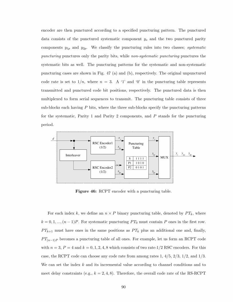
encoder are then punctured according to a specified puncturing pattern. The punctured
data consists of the punctured systematic component ys and the two punctured parity
components y1p and y2p. We classify the puncturing rules into two classes; systematic
puncturing punctures only the parity bits, while non-systematic puncturing punctures the
systematic bits as well. The puncturing patterns for the systematic and non-systematic
puncturing cases are shown in Fig. 47 (a) and (b), respectively. The original unpunctured
code rate is set to 1/n, where n = 3. A ‘1’ and ‘0’ in the puncturing table represents
transmitted and punctured code bit positions, respectively. The punctured data is then
multiplexed to form serial sequences to transmit. The puncturing table consists of three
sub-blocks each having P bits, where the three sub-blocks specify the puncturing patterns
for the systematic, Parity 1 and Parity 2 components, and P stands for the puncturing
period.
Puncturing
Table
RSC Encoder1
(1/2)
Interleaver
d x s
x 1p
x 2p
RSC Encoder2
(1/2)
1 1 1 1
1 0 1 0
0 1 0 1
S
y s
y 1p
y 2p
P1
P2
MUX
y s
y 1p
y 2p
Figure 46: RCPT encoder with a puncturing table.
For each index k, we define an n × P binary puncturing table, denoted by PTk, where
k = 0, 1, ..., (n− 1)P . For systematic puncturing PT0 must contain P ones in the first row.
PTk+1 must have ones in the same positions as PTk plus an additional one and, finally,
PT(n−1)P becomes a puncturing table of all ones. For example, let us form an RCPT code
with n = 3, P = 4 and k = 0, 1, 2, 4, 8 which consists of two rate-1/2 RSC encoders. For this
case, the RCPT code can choose any code rate from among rates 1, 4/5, 2/3, 1/2, and 1/3.
We can set the index k and its incremental value according to channel conditions and to
meet delay constraints (e.g., k = 2, 4, 8). Therefore, the overall code rate of the RS-RCPT
90
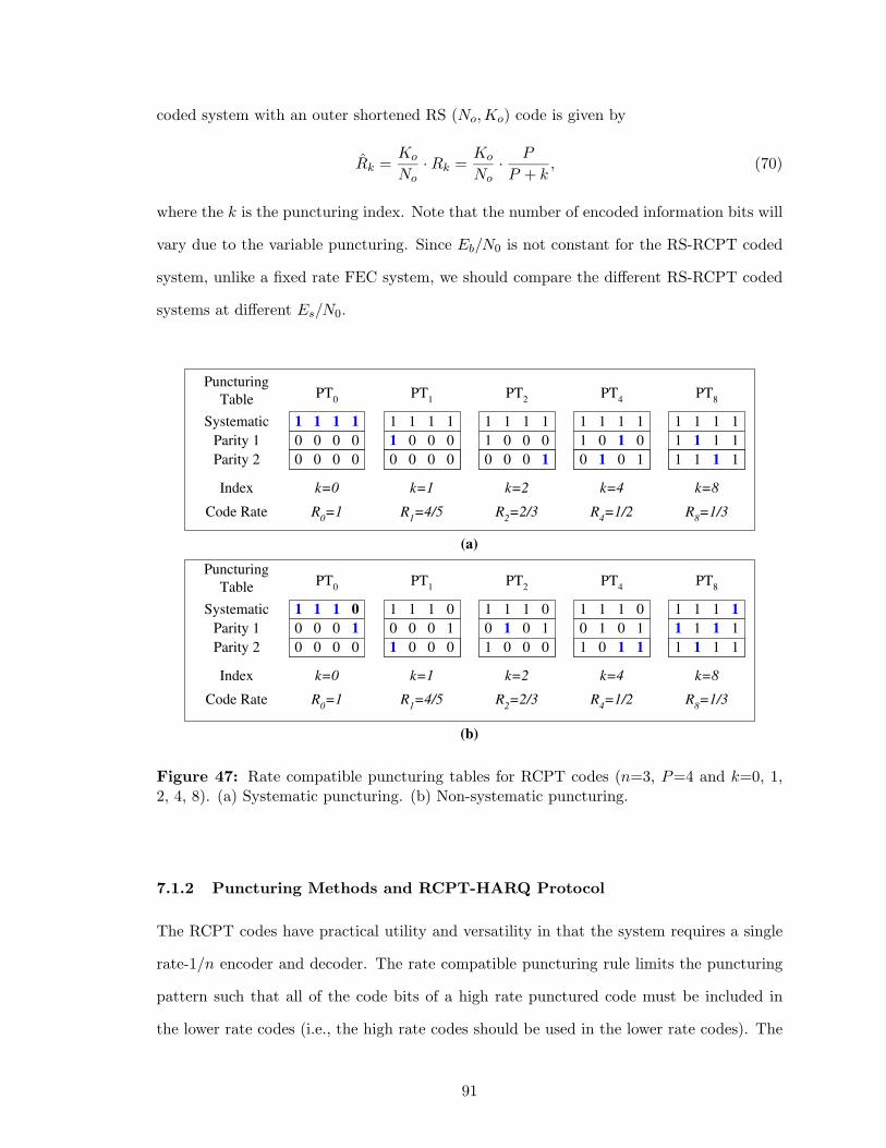
coded system with an outer shortened RS (No, Ko) code is given by
Rk =Ko
No· Rk =
Ko
No· P
P + k, (70)
where the k is the puncturing index. Note that the number of encoded information bits will
vary due to the variable puncturing. Since Eb/N0 is not constant for the RS-RCPT coded
system, unlike a fixed rate FEC system, we should compare the different RS-RCPT coded
systems at different Es/N0.
1 1 1 1
1 0 0 0
0 0 0 1
1 1 1 1
1 0 1 0
0 1 0 1
1 1 1 1
1 1 1 1
1 1 1 1
k=2 k=4 k=8
R 2 =2/3 R
4 =1/2 R
8 =1/3
Systematic
Parity 1
Parity 2
PT 2
PT 4
PT 8
0 0 0 0
0 0 0 0
k=0
R 0 =1
1 1 1 1
PT 0
Index
Code Rate
Puncturing
Table
1 1 1 1
1 0 0 0
0 0 0 0
k=1
R 1 =4/5
PT 1
1 1 1 0
0 1 0 1
1 0 0 0
1 1 1 0
0 1 0 1
1 0 1 1
1 1 1 1
1 1 1 1
1 1 1 1
k=2 k=4 k=8
R 2 =2/3 R
4 =1/2 R
8 =1/3
PT 2
PT 4
PT 8
0 0 0 1
0 0 0 0
k=0
R 0 =1
1 1 1 0
PT 0
1 1 1 0
0 0 0 1
1 0 0 0
k=1
R 1 =4/5
PT 1
Systematic
Parity 1
Parity 2
Index
Code Rate
Puncturing
Table
(a)
(b)
Figure 47: Rate compatible puncturing tables for RCPT codes (n=3, P=4 and k=0, 1,2, 4, 8). (a) Systematic puncturing. (b) Non-systematic puncturing.
7.1.2 Puncturing Methods and RCPT-HARQ Protocol
The RCPT codes have practical utility and versatility in that the system requires a single
rate-1/n encoder and decoder. The rate compatible puncturing rule limits the puncturing
pattern such that all of the code bits of a high rate punctured code must be included in
the lower rate codes (i.e., the high rate codes should be used in the lower rate codes). The
91

transmitter and receiver only share a puncturing table to determine which code bits to
transmit, and the receiver may simply insert erasures for the code bits that have not yet
been received. Therefore, the transmitter need only transmit supplemental code bits to get
to the next lowest rate code.
RS-RCPT-HARQ protocol falls into incremental redundancy codes, in that more bits
are incrementally transmitted to adaptively meet the error performance requirements of the
system. If the decoded frame has detectable errors after a prescribed maximum number of
decoding iterations, the receiver sends a NAK message to the transmitter through a feedback
channel to request the next transmission. If the number of retransmissions exceeds the
maximum number of retransmissions allowed, a decoding failure is declared. We ignore the
effects of finite memory buffer at the receiver and feedback errors on the system performance
for simplicity. Fig. 48 shows a flowchart for the concatenated RS-RCPT-HARQ protocol.
In case of the retransmissions, we use a packet combining scheme to combine the received
frames.
We investigate the throughput and error performance of the RS-RCPT-HARQ scheme
for some families of puncturing tables. It is necessary that at least some non-systematic
parity bits be transmitted so that iterative decoding is possible. Because all decoding
modules share the systematic bits, puncturing the systematic bits of turbo codes gives
more loss than the case of puncturing the non-systematic bits. Given a turbo encoder and
a fixed puncturing period, P , we consider five puncturing methods for selecting puncturing
tables corresponding to the highest rate of the RCPT code:
• Method I (Systematic Puncturing): In the initial transmission (k = 0), transmit all
P systematic code bits. If an error is detected at the receiver, then transmit two code bits
from the non-systematic sub-blocks (k = 2).
• Method II (Non-systematic Puncturing): In the initial transmission (k = 0), transmit
P −1 positions of systematic code bits and 1 code bit from the non-systematic sub-blocks. If
errors are detected at the receiver, the remaining portion of systematic and parity sub-blocks
(k = 2) are transmitted.
• Method III (Non-systematic Puncturing): In the initial transmission (k = 0), puncture
92
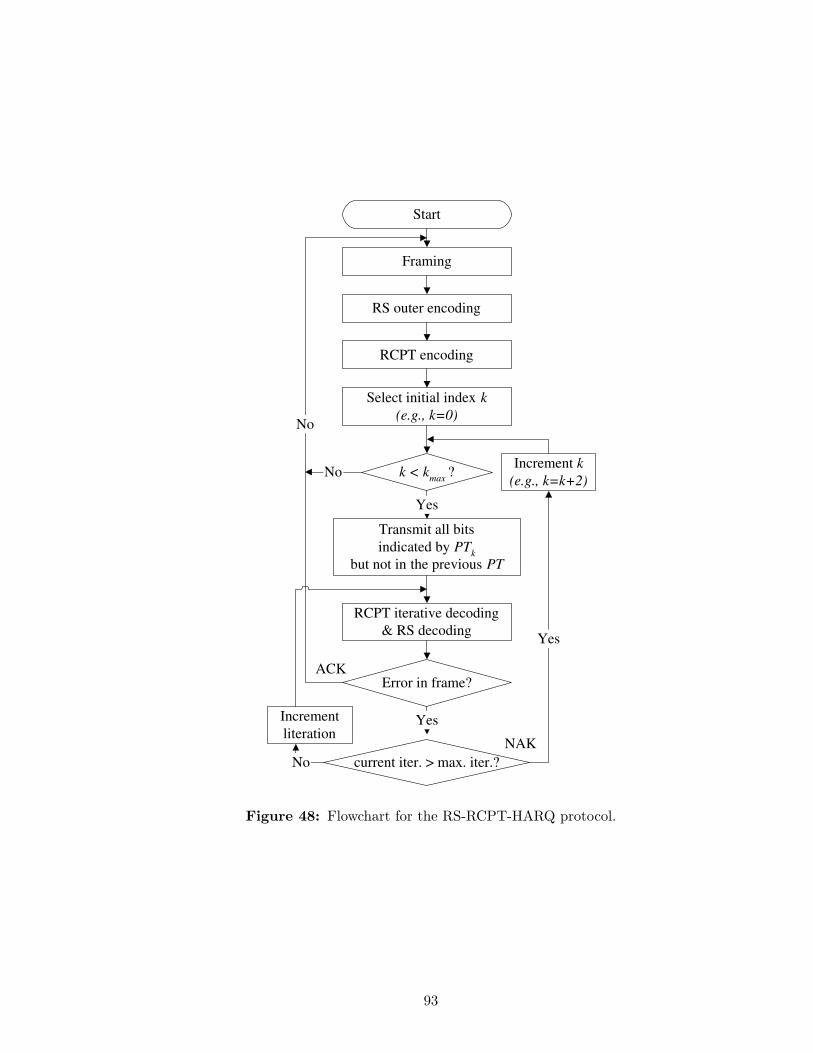
RS outer encoding
RCPT encoding
Transmit all bits
indicated by PT k
b ut not in the previous PT
Select initial index k
(e.g., k=0)
RCPT iterative decoding
& RS decoding
Error in frame?
current iter. > max. iter.?
k < k max
?
Yes
Yes
Increment k
(e.g., k=k+2)
Yes
Increment
literation
No
No
ACK
NAK
No
Framing
Start
Figure 48: Flowchart for the RS-RCPT-HARQ protocol.
93

more than 1 systematic code bit and transmitting instead 1 or more code bits of non-
systematic sub-blocks.
• Method IV (Systematic Puncturing): In the initial transmission (k = 1), transmit P
systematic code bits and 1 non-systematic code bit sub-blocks instead of setting k = 0. If
any error is detected, then transmit additional non-systematic code bits sub-blocks (e.g., k
= 3).
• Method V (Non-systematic Puncturing): In the initial transmission (k = 1), transmit
P − 1 systematic code bits and two non-systematic code bits. If any error is detected, then
transmit additional non-systematic code bits (e.g., k = 3).
From our preliminary simulations, the Method III is first excluded because it always
performed worse than the Method II. The performance of the Method III method is dra-
matically worse for a puncturing period P=4, since half of the systematic bits are punc-
tured in the initial transmission. In case of P=8, we may obtain a performance very
close to that of the Method II by puncturing two positions of systematic bits, but the
throughput will be still better with the Method II. Generally, if a combination of the
puncturing period and the frame size is large enough, it may be advantageous to punc-
ture more than one systematic position in the initial transmission. For the Method I, we
transmit at rates R0 = 8/8, R3 = 8/11, ..., whereas for Method II, we transmit at rates
R1 = 8/9, R2 = 8/10, ....
To achieve more reliability at the sacrifice of additional delay, we repeat the protocol
two additional times and use a code combining scheme to combine received frames for the
puncturing tables of the PH8 family (i.e., the maximum number of transmissions becomes
9). Fig. 49 shows five puncturing tables of the PH8 family. PH8A and PH8B transmit
according to rates Rk with k=0,4,8 (Methods I and II, respectively) for each protocol loop,
while PH8C, PH8D and PH8E transmit according to rates Rk with k=2,5,8, k=4,6,8 and
k=1,5,8, respectively. PH8A falls into the Method I puncturing method that is generated
by systematic puncturing. From the second transmission, puncturing positions of Parity 1
and 2 sub-blocks are equally distributed. PH8B falls into the Method II puncturing method
94
that is generated by non-systematic puncturing (i.e., one position of the systematic sub-
block is punctured and one position of the parity sub-blocks is transmitted) and puncturing
positions in parity sub-blocks are not equally distributed from the second transmission.
PH8C and PH8D falls into the Method IV and are generated by systematic puncturing
(i.e., additional one position and two positions of parity sub-blocks are transmitted at the
first transmission, respectively). Finally, PH8E is a Method V that is generated by non-
systematic puncturing (i.e., one position of systematic sub-block is punctured and additional
two positions of parity sub-blocks are transmitted at the first transmission).
7.1.3 Numerical Results and Discussions
Binary information data is initially encoded by a shortened RS (40, 32) code over GF(256).
The RS encoded data is again encoded by a rate-1/3 RCPT encoder with a puncturing
table having P=4. Two identical 8-state RSC codes with the code generator polynomials,
g = (1 + D + D3/1 + D2 + D3), and an S-random turbo interleaver where S is ⌊√
N/2⌋,
where N is the concatenation interleaver size, are used. The RCPT encoded data is block
interleaved by a channel interleaver before QPSK modulation in same way as the W-CDMA
system in Chapter VI. The simulated frequency-selective fading channel uses the ITU IMT-
2000 Vehicular channel A/B model [87] and the ETSI UMTS Phase 2 channel model [35]
at carrier frequency of 2 GHz and mobile velocity of 30 km/h.
Fig. 50 compares the BER and FER performances of the RS-RCPT coded system for
different code rates. Note that a concatenation interleaver size of 320 bits and S = 12 is
used for the simulations. As the RCPT code rate decreases from R0 = 1 down to R8 = 1/3,
we can obtain an additional coding gain of around 3 ∼ 4 dB for the next lowest code rate
at FER = 10−3. The BER curves show a similar trend as the FER.
Figs. 51 and 52 compare the FER performance of the RS-RCPT coding system for
different puncturing patterns with R4 = 1/2 (denoted as P9) and R2 = 2/3 (denoted as
PA), respectively. To choose a good puncturing pattern for the RCPT code, we compare
puncturing tables for R4 = 1/2 and R2 = 2/3. For the case of R4 = 1/2, the P9 and
P9-1 puncturing tables are better than the others. Because the puncturing positions are
95
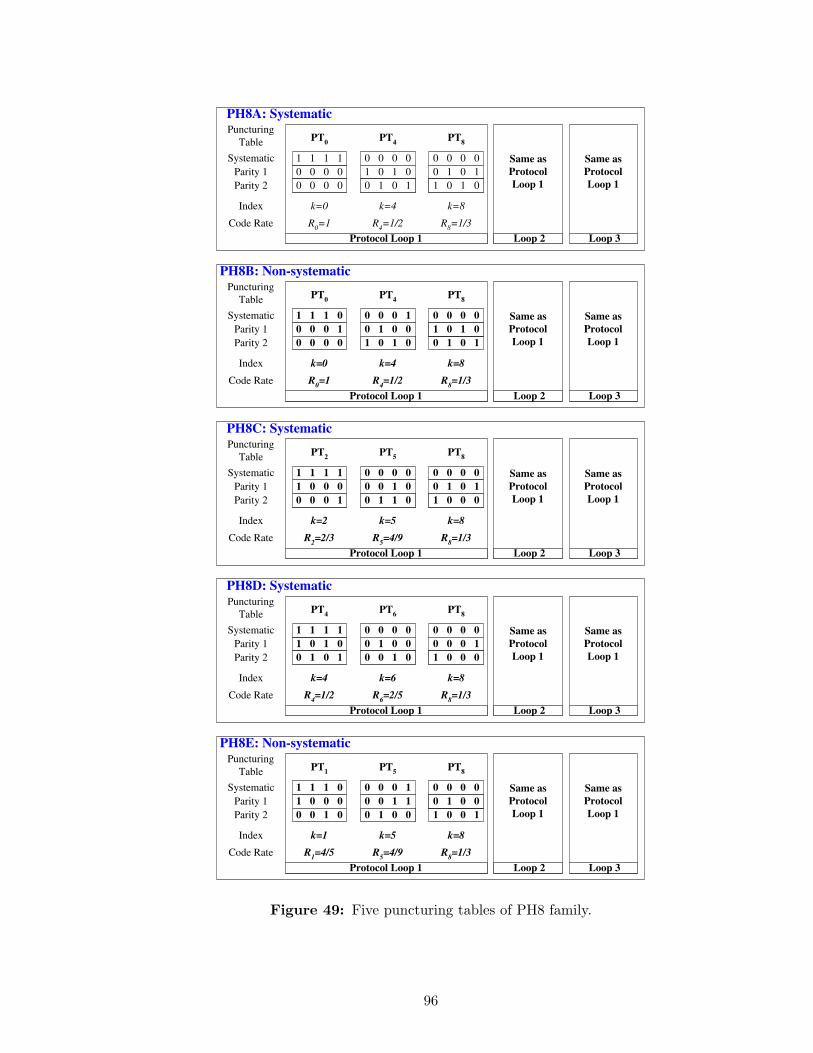
Systematic
Parity 1
Parity 2
Index
Code Rate
Puncturing
Table
PH8A: Systematic
0 0 0 0
0 1 0 1
1 0 1 0
k=8
R 8 =1/3
PT 8
0 0 0 0
0 0 0 0
k=0
R 0 =1
1 1 1 1
PT 0
0 0 0 0
1 0 1 0
0 1 0 1
k=4
R 4 =1/2
PT 4
Same as
Protocol
Loop 1
Protocol Loop 1 Loop 2
Same as
Protocol
Loop 1
Loop 3
Systematic
Parity 1
Parity 2
Index
Code Rate
Puncturing
Table
Same as
Protocol
Loop 1
Protocol Loop 1 Loop 2
Same as
Protocol
Loop 1
Loop 3
0 1 0 1
1 0 1 0
k=8
R 8 =1/3
PT 8
0 0 0 1
0 0 0 0
k=0
R 0 =1
1 1 1 0
PT 0
0 0 0 1
0 1 0 0
1 0 1 0
k=4
R 4 =1/2
PT 4
0 0 0 0
PH8B: Non-systematic
Systematic
Parity 1
Parity 2
Index
Code Rate
Puncturing
Table
PH8C: Systematic
0 0 0 0
0 1 0 1
1 0 0 0
k=8
R 8 =1/3
PT 8
1 0 0 0
0 0 0 1
k=2
R 2 =2/3
1 1 1 1
PT 2
0 0 0 0
0 0 1 0
0 1 1 0
k=5
R 5 =4/9
PT 5
Same as
Protocol
Loop 1
Protocol Loop 1 Loop 2
Same as
Protocol
Loop 1
Loop 3
Systematic
Parity 1
Parity 2
Index
Code Rate
Puncturing
Table
PH8D: Systematic
0 0 0 0
0 0 0 1
1 0 0 0
k=8
R 8 =1/3
PT 8
1 0 1 0
0 1 0 1
k=4
R 4 =1/2
1 1 1 1
PT 4
0 0 0 0
0 1 0 0
0 0 1 0
k=6
R 6 =2/5
PT 6
Same as
Protocol
Loop 1
Protocol Loop 1 Loop 2
Same as
Protocol
Loop 1
Loop 3
Systematic
Parity 1
Parity 2
Index
Code Rate
Puncturing
Table
Same as
Protocol
Loop 1
Protocol Loop 1 Loop 2
Same as
Protocol
Loop 1
Loop 3
1 0 0 1
0 1 0 0
k=8
R 8 =1/3
PT 8
1 0 0 0
0 0 1 0
k=1
R 1 =4/5
1 1 1 0
PT 1
0 0 0 1
0 0 1 1
0 1 0 0
k=5
R 5 =4/9
PT 5
0 0 0 0
PH8E: Non-systematic
Figure 49: Five puncturing tables of PH8 family.
96
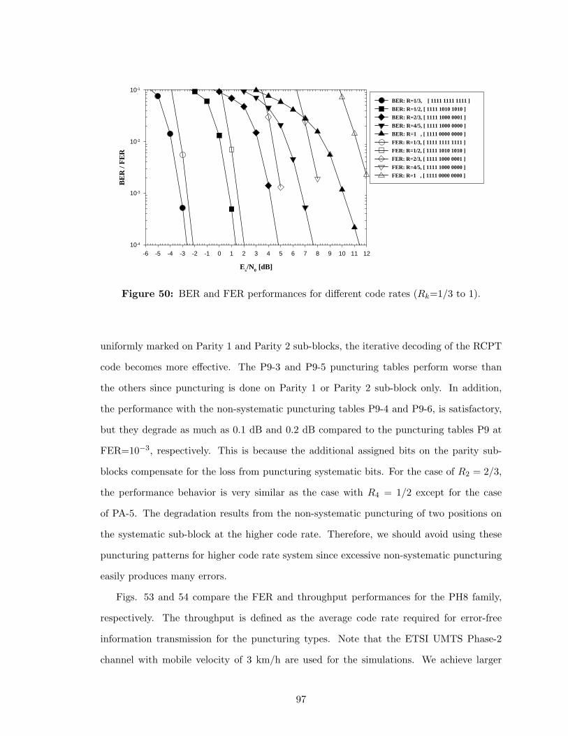
Es/N0 [dB]
-6 -5 -4 -3 -2 -1 0 1 2 3 4 5 6 7 8 9 10 11 12
BE
R /
FE
R
10-4
10-3
10-2
10-1
BER: R=1/3, [ 1111 1111 1111 ]
BER: R=1/2, [ 1111 1010 1010 ]
BER: R=2/3, [ 1111 1000 0001 ]
BER: R=4/5, [ 1111 1000 0000 ]
BER: R=1 , [ 1111 0000 0000 ]
FER: R=1/3, [ 1111 1111 1111 ]
FER: R=1/2, [ 1111 1010 1010 ]
FER: R=2/3, [ 1111 1000 0001 ]
FER: R=4/5, [ 1111 1000 0000 ]
FER: R=1 , [ 1111 0000 0000 ]
Figure 50: BER and FER performances for different code rates (Rk=1/3 to 1).
uniformly marked on Parity 1 and Parity 2 sub-blocks, the iterative decoding of the RCPT
code becomes more effective. The P9-3 and P9-5 puncturing tables perform worse than
the others since puncturing is done on Parity 1 or Parity 2 sub-block only. In addition,
the performance with the non-systematic puncturing tables P9-4 and P9-6, is satisfactory,
but they degrade as much as 0.1 dB and 0.2 dB compared to the puncturing tables P9 at
FER=10−3, respectively. This is because the additional assigned bits on the parity sub-
blocks compensate for the loss from puncturing systematic bits. For the case of R2 = 2/3,
the performance behavior is very similar as the case with R4 = 1/2 except for the case
of PA-5. The degradation results from the non-systematic puncturing of two positions on
the systematic sub-block at the higher code rate. Therefore, we should avoid using these
puncturing patterns for higher code rate system since excessive non-systematic puncturing
easily produces many errors.
Figs. 53 and 54 compare the FER and throughput performances for the PH8 family,
respectively. The throughput is defined as the average code rate required for error-free
information transmission for the puncturing types. Note that the ETSI UMTS Phase-2
channel with mobile velocity of 3 km/h are used for the simulations. We achieve larger
97
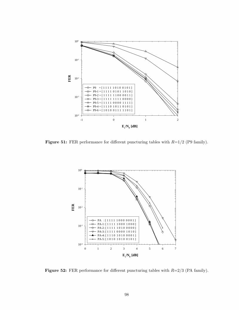
Es/N0 [dB]
-1 0 1 2
FE
R
10-4
10-3
10-2
10-1
100
X
X
X
X
P9 = [ 1 1 1 1 1 0 1 0 0 1 0 1 ]P9-1 = [ 1 1 1 1 0 1 0 1 1 0 1 0 ]P9-2 = [ 1 1 1 1 1 1 0 0 0 0 1 1 ]P9-3 = [ 1 1 1 1 1 1 1 1 0 0 0 0 ]P9-5 = [ 1 1 1 1 0 0 0 0 1 1 1 1 ]P9-4 = [ 1 1 1 0 1 0 1 1 0 1 0 1 ]XP9-6 = [ 1 0 1 0 0 1 1 1 1 1 0 1 ]
Figure 51: FER performance for different puncturing tables with R=1/2 (P9 family).
Es/N0 [dB]
0 1 2 3 4 5 6 7
FE
R
10-4
10-3
10-2
10-1
100
X X XX
X
X
X
PA : [ 1 1 1 1 1 0 0 0 0 0 0 1 ] PA-1: [ 1 1 1 1 1 0 0 0 1 0 0 0 ]PA-2: [ 1 1 1 1 1 0 1 0 0 0 0 0 ]PA-3: [ 1 1 1 1 0 0 0 0 1 0 1 0 ]PA-4: [ 1 1 1 0 1 0 1 0 0 0 0 1 ]PA-5: [ 1 0 1 0 1 0 1 0 0 1 0 1 ]X
Figure 52: FER performance for different puncturing tables with R=2/3 (PA family).
98
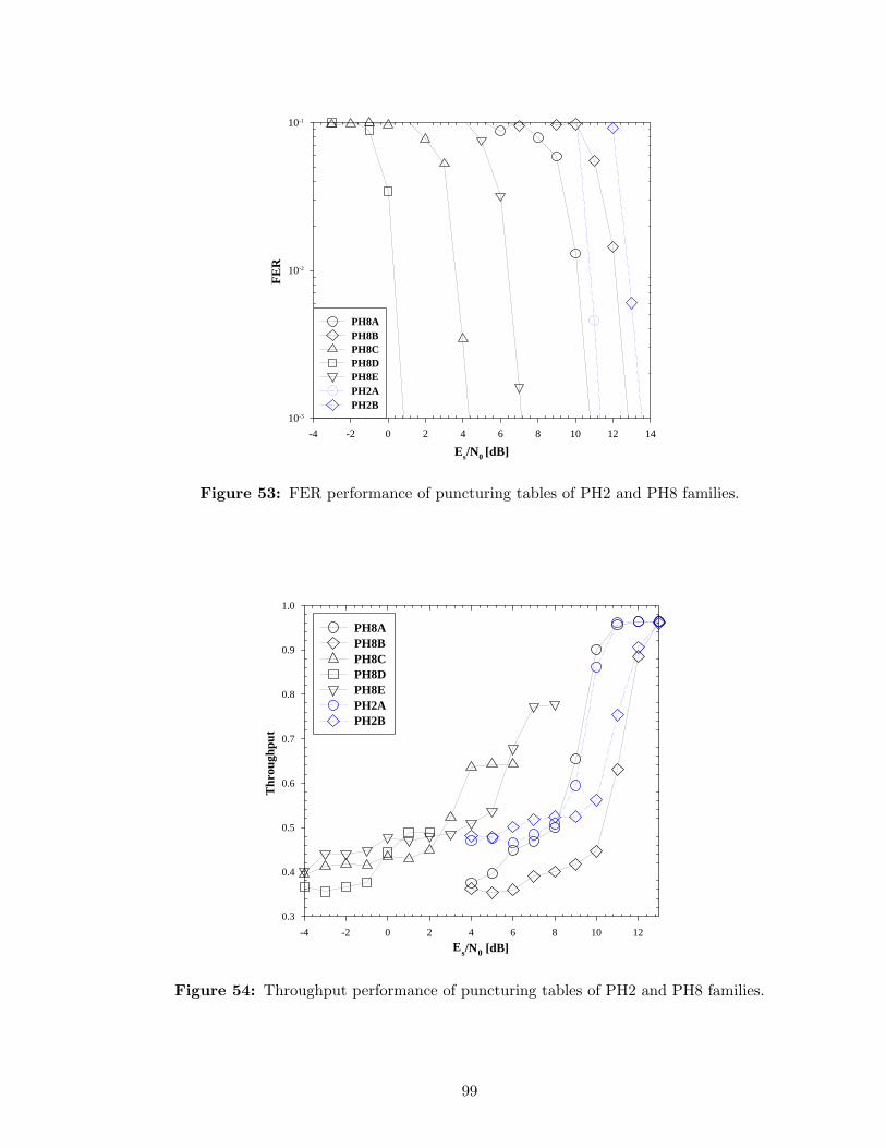
Es/N0 [dB]
-4 -2 0 2 4 6 8 10 12 14
FE
R
10-3
10-2
10-1
PH8APH8BPH8CPH8DPH8EPH2APH2B
Figure 53: FER performance of puncturing tables of PH2 and PH8 families.
Es/N0 [dB]-4 -2 0 2 4 6 8 10 12
Thr
ough
put
0.3
0.4
0.5
0.6
0.7
0.8
0.9
1.0
PH8APH8BPH8CPH8DPH8E PH2APH2B
Figure 54: Throughput performance of puncturing tables of PH2 and PH8 families.
99
coding gain (i.e., PH8D > PH8C > PH8E > PH8A) with the increase in the initial k.
However, throughput decreases. According to the comparison of the FER between the PH8A
and PH2A (and between the PH8B and PH2B), we achieve larger coding gain by employing
hybrid-ARQ and protocol repetition. Note that the PH2A (Method I) and the PH2B
(Method II) correspond to the first protocol loop of the PH8A and PH8B shown in Fig. 49,
respectively. Since the protocol repetition gives rise to more delay and degraded throughput,
we need to adjust the initial k, incremental step and repetition number according to given
service requirements and channel conditions. The PH8B (Method II) gives the worst FER
and throughput performance at the region of medium-to-high SNRs. Note that throughput
is defined as the rate of average received total code bits to information data bits to get
error-free frames and undecoded frames are excluded for the throughput calculation.
7.1.4 Conclusions
To support an adaptive and reliable transmission of packet- and voice-data in hostile mobile
radio channel, we have proposed the concatenated RS-RCPT codes with a variable code
rate up to one. We have proposed the RS-RCPT encoder/decoder and puncturing methods
and investigated the error and throughput performances in W-CDMA system for multipath
fading channels. We have shown that concatenated RS-RCPT codes can correct the burst-
errors and fix the deficiency of the iterative decoder due to the instability and convergence
problem, reducing error-floor by removing residual errors. In addition, to design versatile
retransmission systems using RS-RCPT codes, we have proposed a class of incremental re-
dundancy Type-II RS-RCPT-HARQ scheme. Finally, since there exists a trade-off between
error rate and throughput performances, we should select and adjust the initial value of k,
incremental step, and repetition number according to the QoS requirements and channel
conditions.
100
7.2 Rate Compatible Punctured SCCC
High-speed data services in mobile communications, such as mobile Internet access and
mobile broadcasting, will require a powerful error control coding scheme. Such services
support high data rate and asymmetric transmission such as the 3GPP W-CDMA HSDPA
(High Speed Downlink Packet Access) [1] and 3GPP2 cdma2000 HDR (High Data Rate)
or 1xEV-DO/1xEV-DV [123, 11, 116] systems. Packet-data transmission typically requires
very low BER/FER down to 10−8/10−5 and varying latency ranging from 10 to 80 ms.
To provide different code rates and QoS requirements for hostile wireless channels, an
adaptive error control coding scheme must be used to mitigate time-varying wireless channel
impairments.
Iterative decoding-based PCCC, otherwise known as turbo coding, can provide excellent
coding gains. However, PCCC has a BER/FER flooring effect in the region of moderate-
to-high SNR, i.e., flattening effect of the BER/FER, due to a small number of low weight
codewords [99], while SCCC, an another important class of turbo-like codes, shows little
error flooring problem even with small interleavers [13]. In case of PCCC, BER decreases
approximately as N−1, while in case of SCCC, it typically decreases as N−3, where N is
the concatenation interleaver length. The error-floor effect is a main obstacle to very high
reliability packet transmission. Therefore, SCCC provides better FER performance than
PCCC in the region of moderate-to-high SNR, and is better suited for offering error-free
packet transmission [13]. Moreover, SCCC is less sensitive to interleaver design than PCCC
and makes a more natural code concatenation and a simpler decoder possible. SCCC is more
attractive in that it can be extended to serially concatenated coded modulation schemes
such as BICM.
Rate compatible punctured codes such as RCPC codes [48] and PCCC-based rate com-
patible punctured turbo codes [10], [57], [109], [61] have been shown to provide different
levels of error protection and adaptability to unknown and time-varying channels at the
expense of a small structural change. By combining the high reliability error correcting
capability of SCCC together with a rate compatible puncturing method, we can achieve
adaptive packet-data transmission as well as high reliability due to the interleaving gain and
101
low error-floor. In this chapter, we propose a scheme denoted as rate compatible punctured
SCCC (RCPS) and investigate the error performance on an AWGN and multipath fading
channel for W-CDMA system. Since the RCPS codes have different encoder structure from
the RCPP codes, we need to devise different puncturing methods from that of the RCPP
codes [62]. Comparative results with the RCPP and RCPP-HARQ are also given. In ad-
dition, we propose a concatenated RS-RCPS coding scheme for additional error correction.
Furthermore, by employing an RCPS-HARQ technique based on incremental redundancy
retransmission, we can also obtain similar throughput performance as RCPP-HARQ1.
7.2.1 RCPS Codes and Puncturing Methods
A serial concatenated codes have a probability of error that decreases exponentially as the
frame size increases while the decoding complexity increases linearly [37]. In our work, rate-
1/3 SCCC and PCCC with similar complexity are considered. The schematic structure of
the SCCC encoder is shown in Fig. 55 (a). The SCCC encoder consists of outer and inner
convolutional encoders (including a puncturer, if applicable) with a bitwise concatenation
interleaver between them. The source data sequence uO is first encoded by the outer rate-2/3
encoder. Since the puncturing of the systematic bits causes BER performance degradation
for RSC encoders, rate-2/3 is obtained by puncturing the parity bits. Then the output data
cO is interleaved. Finally, the interleaved data uI is encoded by the inner encoder with rate-
1/2. The output of the inner encoder cI is transmitted through the channel. The detailed
encoder structure of SCCC with constraint length K=3 (4-state) is shown in Fig. 55 (b).
Note that inner encoder must be recursive to achieve the interleaver gain [13]. Although
outer encoder can be non-recursive, an RSC encoder is used here for both inner and outer
encoders.
At the receiver, the additive SISO decoding algorithm that is extended from LOG-MAP
algorithm in [3] is used for iterative decoding of SCCC. PCCC can be decoded by using
SCCC’s additive SISO modules with minor modifications.
RCPS can be designed in a way similar to RCPP by modifying puncturing scheme,
1RCPP is the same as RCPT codes in the thesis.
102
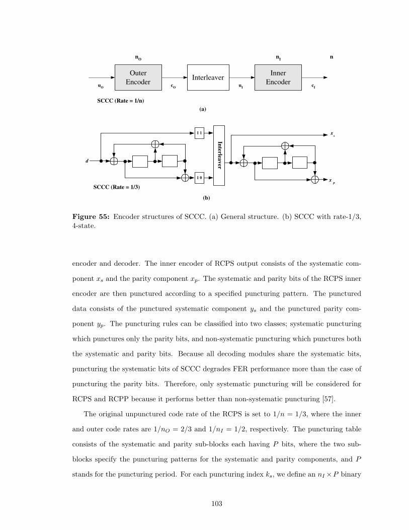
x s
x p
1 1
1 0
Interlea
ver
SCCC (Rate = 1/3)
d
Outer
Encoder
Inner
Encoder Interleaver
u O
u I
c O
c I
n O
n I
n
SCCC (Rate = 1/n)
(a)
(b)
Figure 55: Encoder structures of SCCC. (a) General structure. (b) SCCC with rate-1/3,4-state.
encoder and decoder. The inner encoder of RCPS output consists of the systematic com-
ponent xs and the parity component xp. The systematic and parity bits of the RCPS inner
encoder are then punctured according to a specified puncturing pattern. The punctured
data consists of the punctured systematic component ys and the punctured parity com-
ponent yp. The puncturing rules can be classified into two classes; systematic puncturing
which punctures only the parity bits, and non-systematic puncturing which punctures both
the systematic and parity bits. Because all decoding modules share the systematic bits,
puncturing the systematic bits of SCCC degrades FER performance more than the case of
puncturing the parity bits. Therefore, only systematic puncturing will be considered for
RCPS and RCPP because it performs better than non-systematic puncturing [57].
The original unpunctured code rate of the RCPS is set to 1/n = 1/3, where the inner
and outer code rates are 1/nO = 2/3 and 1/nI = 1/2, respectively. The puncturing table
consists of the systematic and parity sub-blocks each having P bits, where the two sub-
blocks specify the puncturing patterns for the systematic and parity components, and P
stands for the puncturing period. For each puncturing index ks, we define an nI ×P binary
103
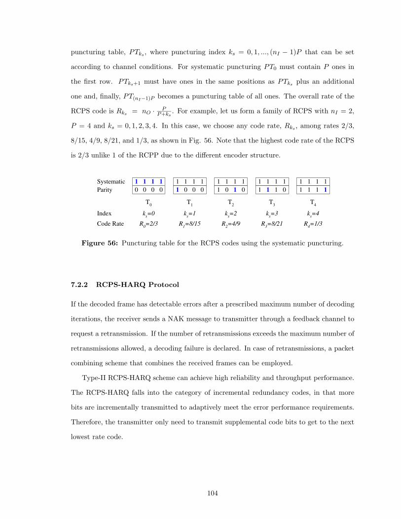
puncturing table, PTks , where puncturing index ks = 0, 1, ..., (nI − 1)P that can be set
according to channel conditions. For systematic puncturing PT0 must contain P ones in
the first row. PTks+1 must have ones in the same positions as PTks plus an additional
one and, finally, PT(nI−1)P becomes a puncturing table of all ones. The overall rate of the
RCPS code is Rks = nO · PP+ks
. For example, let us form a family of RCPS with nI = 2,
P = 4 and ks = 0, 1, 2, 3, 4. In this case, we choose any code rate, Rks , among rates 2/3,
8/15, 4/9, 8/21, and 1/3, as shown in Fig. 56. Note that the highest code rate of the RCPS
is 2/3 unlike 1 of the RCPP due to the different encoder structure.
1 1 1 1
1 0 0
1 1 1 1
1 1 0
1 1 1 1
1 1 1
k s =2 k
s =3 k
s =4
R 2 =4/9 R
3 =8/21 R
4 =1/3
Systematic
Parity 0 0 0 0
k s =0
R 0 =2/3
1 1 1 1
Index
Code Rate
1 1 1 1
1 0 0 0
k s =1
R 1 =8/15
1 1 1
T 0
T 1
T 2
T 3
T 4
Figure 56: Puncturing table for the RCPS codes using the systematic puncturing.
7.2.2 RCPS-HARQ Protocol
If the decoded frame has detectable errors after a prescribed maximum number of decoding
iterations, the receiver sends a NAK message to transmitter through a feedback channel to
request a retransmission. If the number of retransmissions exceeds the maximum number of
retransmissions allowed, a decoding failure is declared. In case of retransmissions, a packet
combining scheme that combines the received frames can be employed.
Type-II RCPS-HARQ scheme can achieve high reliability and throughput performance.
The RCPS-HARQ falls into the category of incremental redundancy codes, in that more
bits are incrementally transmitted to adaptively meet the error performance requirements.
Therefore, the transmitter only need to transmit supplemental code bits to get to the next
lowest rate code.
104
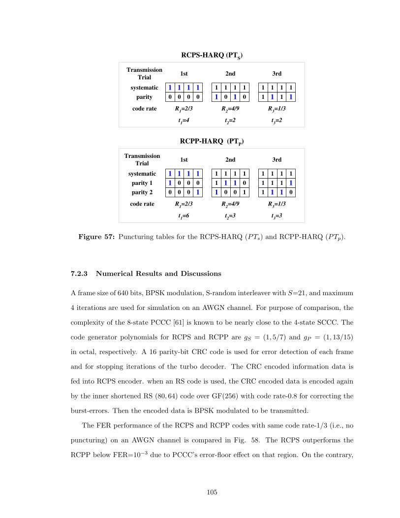
systematic
parity 0 0 0 0
R 1 =2/3
1 1 1 1
1st
code rate
1 0 1 0
R 2 =4/9
2nd
1 1 1 1
1 1 1 1
3rd
1 1 1 1
R 3 =1/3
RCPS-HARQ (PT S )
systematic
parity 1
parity 2
1 0 0 0
R 1 =2/3
1 1 1 1
1st
code rate
1 1 1 0
R 2 =4/9
2nd
1 1 1 1
1 0 0 1 0 0 0 1
1 1 1 1
R 3 =1/3
3rd
1 1 1 1
1 1 1 0
RCPP-HARQ (PT P )
Transmission
Trial
Transmission
Trial
t 1 =4 t
2 =2 t
3 =2
t 1 =6 t
2 =3 t
3 =3
Figure 57: Puncturing tables for the RCPS-HARQ (PTs) and RCPP-HARQ (PTp).
7.2.3 Numerical Results and Discussions
A frame size of 640 bits, BPSK modulation, S-random interleaver with S=21, and maximum
4 iterations are used for simulation on an AWGN channel. For purpose of comparison, the
complexity of the 8-state PCCC [61] is known to be nearly close to the 4-state SCCC. The
code generator polynomials for RCPS and RCPP are gS = (1, 5/7) and gP = (1, 13/15)
in octal, respectively. A 16 parity-bit CRC code is used for error detection of each frame
and for stopping iterations of the turbo decoder. The CRC encoded information data is
fed into RCPS encoder. when an RS code is used, the CRC encoded data is encoded again
by the inner shortened RS (80, 64) code over GF(256) with code rate-0.8 for correcting the
burst-errors. Then the encoded data is BPSK modulated to be transmitted.
The FER performance of the RCPS and RCPP codes with same code rate-1/3 (i.e., no
puncturing) on an AWGN channel is compared in Fig. 58. The RCPS outperforms the
RCPP below FER=10−3 due to PCCC’s error-floor effect on that region. On the contrary,
105
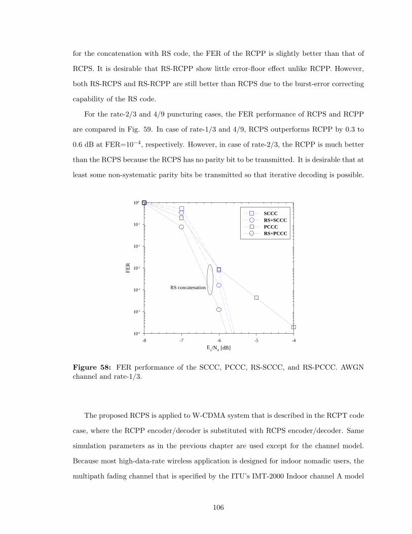
for the concatenation with RS code, the FER of the RCPP is slightly better than that of
RCPS. It is desirable that RS-RCPP show little error-floor effect unlike RCPP. However,
both RS-RCPS and RS-RCPP are still better than RCPS due to the burst-error correcting
capability of the RS code.
For the rate-2/3 and 4/9 puncturing cases, the FER performance of RCPS and RCPP
are compared in Fig. 59. In case of rate-1/3 and 4/9, RCPS outperforms RCPP by 0.3 to
0.6 dB at FER=10−4, respectively. However, in case of rate-2/3, the RCPP is much better
than the RCPS because the RCPS has no parity bit to be transmitted. It is desirable that at
least some non-systematic parity bits be transmitted so that iterative decoding is possible.
Es/N0 [dB]
-8 -7 -6 -5 -4
FER
10-6
10-5
10-4
10-3
10-2
10-1
100
SCCCRS+SCCCPCCCRS+PCCC
RS concatenation
Figure 58: FER performance of the SCCC, PCCC, RS-SCCC, and RS-PCCC. AWGNchannel and rate-1/3.
The proposed RCPS is applied to W-CDMA system that is described in the RCPT code
case, where the RCPP encoder/decoder is substituted with RCPS encoder/decoder. Same
simulation parameters as in the previous chapter are used except for the channel model.
Because most high-data-rate wireless application is designed for indoor nomadic users, the
multipath fading channel that is specified by the ITU’s IMT-2000 Indoor channel A model
106
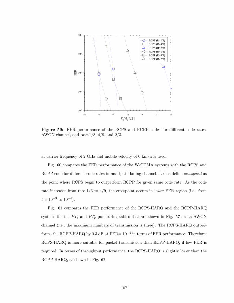
Es/N0 [dB]-8 -6 -4 -2 0 2 4
FER
10-5
10-4
10-3
10-2
10-1
RCPS (R=1/3)RCPS (R=4/9)RCPS (R=2/3)RCPP (R=1/3)RCPP (R=4/9)RCPP (R=2/3)
Figure 59: FER performance of the RCPS and RCPP codes for different code rates.AWGN channel, and rate-1/3, 4/9, and 2/3.
at carrier frequency of 2 GHz and mobile velocity of 0 km/h is used.
Fig. 60 compares the FER performance of the W-CDMA systems with the RCPS and
RCPP code for different code rates in multipath fading channel. Let us define crosspoint as
the point where RCPS begin to outperform RCPP for given same code rate. As the code
rate increases from rate-1/3 to 4/9, the crosspoint occurs in lower FER region (i.e., from
5 × 10⁻³ to 10−4).
Fig. 61 compares the FER performance of the RCPS-HARQ and the RCPP-HARQ
systems for the PTs and PTp puncturing tables that are shown in Fig. 57 on an AWGN
channel (i.e., the maximum numbers of transmission is three). The RCPS-HARQ outper-
forms the RCPP-HARQ by 0.3 dB at FER= 10−4 in terms of FER performance. Therefore,
RCPS-HARQ is more suitable for packet transmission than RCPP-HARQ, if low FER is
required. In terms of throughput performance, the RCPS-HARQ is slightly lower than the
RCPP-HARQ, as shown in Fig. 62.
107
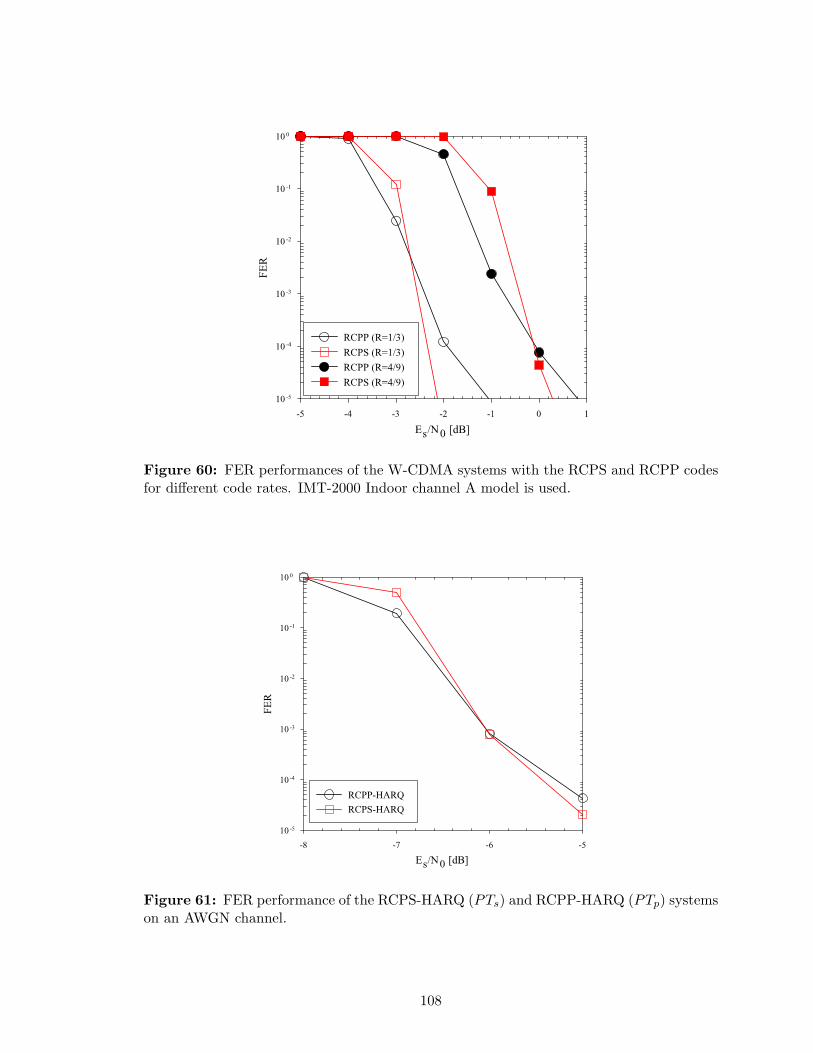
Figure 60: FER performances of the W-CDMA systems with the RCPS and RCPP codesfor different code rates. IMT-2000 Indoor channel A model is used.
Figure 61: FER performance of the RCPS-HARQ (PTs) and RCPP-HARQ (PTp) systemson an AWGN channel.
108

Figure 62: Throughput performance of the RCPS-HARQ (PTs) and RCPP-HARQ (PTp)systems on an AWGN channel.
7.2.4 Conclusions
We have proposed the RCPS codes using an SCCC, an another important class of turbo-
like codes that is widely used, to accommodate different code rates and very low FER
requirements for high-speed packet-data transmission. We have also proposed the punctur-
ing methods that are well matched to the RCPS codes and shown that the RCPS codes
provide lower FER than that of the RCPP codes in the region of moderate-to-high SNR.
We have investigated the performance of the RCPS and RS-RCPS codes on an AWGN and
multipath fading channels. Comparative results with the RCPP codes have also been pre-
sented. In addition, we have proposed a Type-II RCPS-HARQ scheme using incremental
redundancy retransmission to achieve a lower FER than that of RCPP-HARQ at the slight
cost of throughput.
109
CHAPTER VIII
CONCLUDING REMARKS
8.1 Summary of Contributions
In this thesis, we have presented advanced error control schemes using turbo-like codes,
turbo-like coded modulations, turbo hybrid-ARQ schemes, and rate compatible punctur-
ing techniques for commercial and tactical spread-spectrum communications, especially for
CDMA cellular systems and DS and FH anti-jam systems. ML bounding techniques and
convergence analysis have also been utilized because they offer good benchmarks for the
error performance comparison and evaluation of the suboptimal iterative receivers and help
us to construct effective turbo-like coding schemes.
The main contributions and results of the thesis are as follows.
In Chapter III, we have proposed a power and bandwidth efficient DS concatenated
coded CPM system. Block-wise interleaving has been shown to outperform chip-wise in-
terleaving. A mixed concatenated coded CPM system with a proper mixture ratio has
been shown to improve the anti-jamming performance. Finally, the error-floor phenomenon
for MCC in the case of a large mixture ratio has been explained by the poor decoding
convergence through the convergence analysis.
In Chapter IV, we have presented the coherent and non-coherent anti-jam serially con-
catenated slow FH-CPM systems. Through simulation and ML bound analysis, we have
showed the anti-jamming performance in the presence of the PBNJ. Consequently, we have
drawn some important design considerations with regard to the outer convolutional codes
and the inner CPMs as well as FH parameters. We have also shown that better anti-
jamming capability is achieved as the decoding iteration increases. And, the MSDD-based
non-coherent iterative receiver exploiting channel memory performs close to the coherent
one with increase in the observation interval. In addition, it has been shown that an outer
code with larger state does not necessary provide better anti-jamming performance at low
110
Eb/NJ as opposed to the bound analysis at high Eb/NJ . Furthermore, we have presented a
novel iterative jamming estimation technique combined with the anti-jam iterative receiver
for the serially concatenated slow FH-CPM system. We have compared the anti-jamming
performance in the presence of partial and no jamming information.
In Chapter V, we have proposed serially concatenated multi-h CPM with iterative de-
modulation and decoding. We have shown that a channel code with larger minimum dis-
tance, or a multi-h CPM modulator with a larger number of phase states do not necessary
provide better BER performance. Candidate choices for the modulation index set can eval-
uated by using convergence characteristics and the multi-h modulator should be matched
to the channel code. We have also evaluated performance in the error-floor region through
union-Chernoff bounding techniques.
In Chapter VI, we have proposed a Type-I turbo hybrid-ARQ scheme using a concate-
nated RS-turbo code and a packet combining technique for W-CDMA system to improve
the error and decoding latency performances. For coherent W-CDMA system, we have con-
sidered the fast power control and Rake receiver with a multipath fading channel estimation
technique.
Finally, in Chapter VII, we have proposed rate compatible punctured turbo-like codes
using PCCC and SCCC to offer versatile coded systems. Puncturing methods and strategy
have been classified and compared in terms of the error and throughput performances.
In addition, we have proposed Type-II RCPT-HARQ and RCPS-HARQ schemes using
incremental redundancy retransmission for improving reliability and throughput.
8.2 Suggestions for Future Research
We propose the following suggestions for future research.
• Turbo-like coded space-time modulation for spread-spectrum
To achieve higher data rates, the multiple-input multiple-output (MIMO) wireless
communication systems can theoretically increase capacity by up to a factor equaling
the number of transmit and receive antennas. In addition, powerful turbo-like coding
and low-complexity iterative detection can dramatically improve the spread-spectrum
111
systems subject to hostile jamming/interference and, thus, improve the LPI/LPD
performance. Therefore, spread-spectrum systems based on low-complexity turbo-
like coded space-time modulation schemes that properly exploit the turbo principle
for concatenated codes and recursive differential space-time modulation (DSTM) is a
promising topic for research.
• Anti-jam spread-spectrum systems with graphical codes
Recently, graphical codes such as LDPC and tree codes showed comparable error
performance to turbo codes. However, anti-jam spread-spectrum systems using these
codes are yet to be studied in details. In addition, it will be useful to use the analysis
frameworks of graphical codes to analyze the performance.
• Turbo hybrid-ARQ schemes for MIMO systems and adaptive modulation and coding
Turbo hybrid-ARQ schemes that are extended to MIMO environments will be inter-
esting. Further, hybrid-ARQ schemes with an adaptive modulation or adaptive power
control technique have a potential to improve the overall system performance.
112
APPENDIX A
UNION BOUNDS ON THE PERFORMANCE OF ML
DECODING FOR SCCC
Although the bound on the performance of ML decoding of turbo-like codes, which use a
suboptimal decoder, becomes prohibitively complex for very long codes and diverges in low
SNR region, the ML bound is still an invaluable practical tool for the design and analysis
and sets a benchmark for the comparison of the practical suboptimal decoding methods.
The most commonly used upper bound on the error probability of a digital communication
system is union bound. For the calculation of the union bound for a binary block code, one
only needs to have the input-output weight enumerating function (or distance spectrum) of
the code.
In this appedix, we present the union bound on performance for the serially concatenated
convolutional code (SCCC) with coherent detection on an AWGN channel. The SCCCs
include RA codes, serially concatenated DPSK, and serially concatenated CPM. We use
the transfer function bounding approach in [13] to obtain the ensemble input-output weight
enumerating function (IOWEF). The performance of the SCCC can be approximated by
that of the equivalent block code whose IOWEF labels the branch of the hyper-trellis joining
the zero states of outer- and inner-code trellises1.
Consider an SCCC Cs with the overall rate R = m/p consists of the outer convolutional
code Co with rate Ro = m/n, and the inner convolutional code Ci with rate Ri = n/p,
joined by an interleaver of length N . The weight enumerating function (WEF) of the code
is defined as [126]
A(H)△=
p∑
d=0
AdHd, (71)
where Ad represents the number of codewords with Hamming weight d and H is a dummy
1Terminated convolutional codes are used.
113
variable and is referred to as the WEF coefficient. Note that the WEF provides the weight
distribution which only depends on the codewords. The more detailed IOWEF is defined
as [126]
A(W, H)△=
m∑
w=0
p∑
d=0
Aw,dWwHd (72)
=m∑
w=0
WwA(w, H) (73)
=p∑
d=0
HdA(W, d), (74)
where Aw,d represents the number of codewords with weight d associated with an in-
formation words of weight w and is referred to as the IOWEF coefficient or the input-
output weight spectrum, and the conditional input weight enumerating function (CIWEF)
is A(W, d)△=∑m
w=0 Aw,dWw. And, the conditional output weight enumerating function
(COWEF) is A(w, H)△=∑p
d=0 Aw,dHd and enumerates the weight distribution of codewords
generated by information words of a given weight w. The relationship between A(w, H)
and A(W, H) is
A(w, H) =1
w!
∂wA(W, H)
∂Ww
∣
∣
∣
∣
W=0. (75)
The pairwise error probability, denoted by Ppw(d), between a codeword of weight d and the
all-zero codeword on an AWGN channel is given by
Ppw(d) = Q
(√
d2REb
N0
)
=1
2erfc
(√
dREb
N0
)
< e−d
REbN0 , (76)
where Q(x)△= 1√
2π
∫∞x e−λ2/2dλ = 1
2erfc(x/√
2).
Therefore, we can obtain a closed-form upper bound on BEP under ML soft-decision
decoder by assuming all-zero transmitting sequence as below
Pb△=
m∑
w=1
Pb(w) ≤N/Ri∑
d=dm
NRo∑
w=wom
w
NRoAw,dPpw(d), (77)
where wom is the minimum weight of an input sequence generating an error event of the
outer code, dm of a length-N compound error event is the minimum weight of the code-
words for the SCCC, Aw,d represents the ensemble IOWEF for the SCCC. Note that
114
Bd△=∑NRo
w=wom
wNRo Aw,d represents the bit error multiplicity for error events2 and is de-
pendent on d. The Chernoff bounds for BEP and WEP are given by
Pb ≤N/Ri∑
d=dm
NRo∑
w=wom
w
NRoAw,dH
d =1
NRo
∂A(W, H)
∂W
∣
∣
∣
W=1, (78)
and
Pw ≤N/Ri∑
d=dm
NRo∑
w=wom
Aw,d
Hd = A(W, H)|W=1, (79)
respectively. Also, (77) can be rewritten using (74) and (76) as
Pb <NRo∑
w=wom
w
NRoA(w, H)|H=e−REb/N0 . (80)
In addition, the ensemble IOWEF Aw,d can be obtained by calculating Aow,l and Ai
l,d
and assuming the uniform interleaver of length N as
Aw,d =N∑
l=0
Aow,l · Ai
l,d(N
l
). (81)
The probabilistic uniform interleaving is devised in [13] to map a given input sequence
of length N and weight l into its all distinct(N
l
)
permutations with equal probability
of 1/(N
l
)
= l!(N − l)!/N !. The premise is that there is at least one interleaver, which
performs better than the average. The weight enumerating function of sequences of the
convolutional code that concatenate j error events with total input information weight l is
given by A(l, H, j) =∑
d Al,d,jHd, where Al,d,j represents the number of sequences of weight
d, input weight l, and number of concatenated error events j. The coefficient Al,d can be
upper-bounded as Al,d ≤ ∑nMj=1
(N/nj
)
Al,d,j , where nM is the largest number of error events
concatenated in a codeword of weight d and generated by a weight l information sequence.
With j = no and j = ni for the outer and inner code, respectively, we can rewrite Aw,d3 as
Aw,d ≤N∑
l=dof
noM∑
no=1
niM∑
ni=1
(N/nno
)(N/nni
)
(Nl
)Ao
w,l,noAil,d,ni , (82)
where dof is the free distance of the outer code4.
2It is sometimes called the bit-normalized weight enumerating function (BNWEF).3Clearly, A0,0 = 1 by linearity.4do
f is set as the lower limit because there can be no less than dof ones in the N -symbol outer code
sequence.
115
Since the error-floor is mostly affected by a few codewords of low-weight, a truncated
bound considering only the low-weight codewords can be used for an approximation [133],
[38], [119].
Note that we can further bound the binomial functions using
Nn
nnn!<
(N − n + 1)n
n!<
(
N
n
)
<Nn
n!. (83)
Finally, substitution of these bounds in (82) yields the bound in the form all-zero trans-
mitting sequence as below
Pb ≤N/Ri∑
d=dm
Ppw(d)NRo∑
w=wom
N∑
l=dof
noM∑
no=1
niM∑
ni=1
NβM−1 lll!
nno+ni−1no!ni!
w
NRoAo
w,l,noAil,d,ni , (84)
where βM = no + ni − l.
For very high values of SNR, Pw and Pb are given by
Pb ≤1
2
wfree
kerfc
(√
dfreeREb
N0
)
, (85)
and
Pw ≤ 1
2Nfreeerfc
(√
dfreeREb
N0
)
, (86)
where dfree, Nfree, and wfree denote the free distance of the code, its multiplicity, and its
information bit multiplicity, respectively. Note that Nfree = Afreed and wfree = Bfree
d .
116

APPENDIX B
TRANSFER CHARACTERISTICS FOR THE JAMMING
CHANNEL
In this appendix, we derive the extrinsic information transfer characteristics for the pulse
jamming channel. The channel LLR-values assuming known JSI z at the receiver are cal-
culated as
L = log
[
P (y|x = +1, z)
P (y|x = −1, z)
]
=exp
{
− (y−1)2
2σ2z
}
/√
2πσ2z
exp{
− (y+1)2
2σ2z
}
/√
2πσ2z
= 2y/σ2z , (87)
where y = x+nJ with the transmitted binary symbols x ∈ {±1} and nJ is the AWGN and
jamming noise vector. Thus, (87) can be rewritten as
L =2
σ2z
· (x + nJ), (88)
where variable nJ is Gaussian distributed with mean zero and variance σ2z = N0/2+z·NJ/2ρ.
Furthermore, (88) can be represented as L = νL ·x+nL, where mean νL = 2/σ2z and variance
σ2L = 4/σ2
z . Hence, the conditional PDF for the LLR-value L is calculated as
p(λ|X = x) =1
√
2πσ2L
exp
{
−(λ − νL · x)2
2σ2L
}
. (89)
117
REFERENCES
[1] 3GPP, “High speed downlink packet access (HSDPA),” TR 25.855, 3rd GenerationPartnership Project, Jun. 2001.
[2] Adachi, F., Sawahashi, M., and Suda, H., “Wideband DS-CDMA for next-generation mobile communications systems,” IEEE Commun. Mag., vol. 36, pp. 56–69, Sept. 1998.
[3] Ambroze, A., Wade, G., and Tomlinson, M., “Iterative MAP decoding for serialconcatenated convolutional codes,” IEE Proc. Commun., vol. 145, pp. 53–59, Apr.1998.
[4] Anderson, J. B., Aulin, T., and Sundberg, C.-E., Digital Phase Modulation.New York: Plenum Press, 1986.
[5] Anderson, J. B. and Taylor, D. P., “A bandwidth-efficient class of signal-spacecodese,” IEEE Trans. Inform. Theory, vol. 24, pp. 703–712, Nov. 1978.
[6] Andoh, H., Sawahashi, M., and Adachi, F., “Channel estimation filter using time-multiplexed pilot channel for coherent Rake combining in DS-CDMA mobile radio,”IEICE Trans. Commun., vol. E81-B, pp. 1517–1526, Jul. 1998.
[7] Asano, D. K., Hayashi, T., and Kohno, R., “Modulation and processing gaintradeoffs in DS-CDMA spread spectrum systems,” in Proc. IEEE ISSSTA ’98, (SunCity, South Africa), pp. 9–13, Sept. 1998.
[8] Aulin, T. and Sundberg, C.-E., “On the minimum Euclidean distance for a classof signal space codes,” IEEE Trans. Inform. Theory, vol. 28, pp. 43–55, Jan. 1982.
[9] Bahl, L. R., Cocke, J., Jelinek, F., and Raviv, J., “Optimal decoding of lin-ear codes for minimizing symbol error rate,” IEEE Trans. Inform. Theory, vol. 20,pp. 284–287, Mar. 1974.
[10] Barbulescu, A. S. and Pietrobon, S. S., “Rate compatible turbo-codes,” IEEElectron. Letters, vol. 31, pp. 535–536, Mar. 1995.
[11] Bender, P., Black, P., Grob, M., Padovani, R., Sindhushyana, N., andViterbi, S., “CDMA/HDR: A bandwidth efficient high speed wireless data servicefor nomadic users,” IEEE Commun. Mag., vol. 38, pp. 70–77, Jul. 2000.
[12] Benedetto, S., Divsalar, D., Montorsi, G., and Pollara, F., “Algorithm forcontinuous decoding of turbo codes,” IEE Electron. Letters, vol. 32, pp. 314–315, Feb.1996.
[13] Benedetto, S., Divsalar, D., Montorsi, G., and Pollara, F., “Serial concate-nation of interleaved codes: Performance analysis, design, and iterative decoding,”IEEE Trans. Inform. Theory, vol. 44, pp. 909–926, May 1998.
118
[14] Benedetto, S. and Montorsi, G., “Design of parallel concatenated convolutionalcodes,” IEEE Trans. Commun., vol. 44, pp. 591–600, May 1996.
[15] Benedetto, S. and Montorsi, G., “Unveiling turbo codes: Some results on parallelconcatenated coding schemes,” IEEE Trans. Info. Theory, vol. 42, pp. 409–428, Mar.1996.
[16] Berlekamp, E. R., “The technology of error correction codes,” Proc. IEEE, vol. 68,pp. 564–593, May 1980.
[17] Berrou, C. and Glavieux, A., “Near optimum error correcting coding and decod-ing: turbo-codes,” IEEE Trans. Commun., vol. 44, pp. 1261–1271, Oct. 1996.
[18] Berrou, C., Glavieux, A., and Thitimajshima, P., “Near shannon limit error-correcting coding and decoding: Turbo codes,” in Proc. IEEE ICC ’93, (Geneva,Switzerland), pp. 1064–1070, May 1993.
[19] Brendler, J. A., “Tactical military communications,” IEEE Commun. Mag.,vol. 30, pp. 67–72, Jan. 1992.
[20] Cain, J. B., Clark, G. C., and Geist, J. M., “Punctured convolutional codes ofrate (n − 1)/n and simplified maximum likelihood decoding,” IEEE Trans. Inform.Theory, vol. 25, pp. 97–100, Jan. 1979.
[21] Callendar, M. H. and et al., “Special issue on IMT-2000: Standards efforts ofthe ITU,” IEEE Personal Commun., vol. 4, Aug. 1997.
[22] Chase, D., “Code combining - a maximum-likelihood decoding approach for combin-ing an arbitrary number of noisy packets,” IEEE Trans. Commun., vol. 33, pp. 385–393, May 1985.
[23] Cover, T. M. and Thomas, J. A., Elements of Information Theory. New York:John Wiley & Sons, 1991.
[24] Dai, H. and Poor, V., “Turbo multiuser detection for coded DMT VDSL systems,”IEEE J. Select. Areas Commun., vol. 20, pp. 351–362, Feb. 2002.
[25] Divsalar, D., “A simple tight bound on error probability of block codes with appli-cation to turbo codes,” JPL TMO Progress Report, pp. 1–35, Nov. 1999.
[26] Divsalar, D., Dolinar, S., and Pollara, F., “Improving turbo-like codes usingiterative decoder analysis,” in Proc. IEEE ISIT ’01, (Washington, DC), p. 100, Jun.2001.
[27] Divsalar, D., Dolinar, S., and Pollara, F., “Iterative turbo decoder analysisbased on density evolution,” IEEE J. Select. Areas Commun., vol. 19, pp. 891–907,May 2001.
[28] Divsalar, D., Jin, H., and McEliece, R. J., “Coding theorems for turbo-likecodes,” in Proc. 36th Annual Allerton Conf. on Commun., Control, and Comp., (Ur-bana, IL), pp. 201–210, Sept. 1998.
[29] Divsalar, D. and Pollara, F., “Turbo codes for PCS applications,” in Proc. IEEEICC ’95, (Seattle, WA), pp. 54–59, Jun. 1995.
119
[30] Divsalar, D. and Pollara, S., “Low-rate turbo codes for deep-space communica-tions,” in Proc. IEEE ISIT ’95, (Whistler, Canada), p. 35, Sept. 1995.
[31] Dolinar, S. and Divsalar, D., “Weight distributions for turbo codes using randomand nonrandom permutations,” JPL TDA Progress Report, pp. 56–65, Aug. 1995.
[32] Drukarev, A. and Costello, Jr., D., “A comparison of block and convolutionalcodes in ARQ error control schemes,” IEEE Trans. Commun., vol. 30, pp. 2449–2455,Nov. 1982.
[33] Duman, T. M., Turbo codes and turbo coded modulation systems: Analysis and per-formance bounds. PhD thesis, Northeastern University, Boston, MA, May 1998.
[34] Duman, T. M. and Salehi, M., “New performance bounds for turbo codes,” IEEETrans. Commun., vol. 46, pp. 717–723, Jun. 1998.
[35] ETSI, UMTS SMG2 L1 Documents. 1998-1999.
[36] Fonseka, J. P. and Davis, G. R., “Combined coded/multi-h CPFSK signaling,”IEEE Trans. Commun., vol. 38, pp. 1708–1715, Oct. 1990.
[37] Forney, G. D., Concatenated Codes. Boston, MA: MIT Press, 1966.
[38] Fossorier, M. P. C., Lin, S., and Costello, Jr., D. J., “On the weight dis-tribution of terminated convolutional codes,” IEEE Trans. Inform. Theory, vol. 45,pp. 1646–1648, Jul. 1999.
[39] Frank, C. D. and Pursley, M. B., “Concatenated coding for frequency-hop spread-spectrum with partial-band interference,” IEEE Trans. Commun., vol. 44, pp. 377–387, Mar. 1996.
[40] Gagnon, F. and Haccoun, D., “Bounds on the error performance of coding fornonindependent rician-fading channels,” IEEE Trans. Commun., vol. 40, pp. 351–360, Feb. 1992.
[41] Gallager, R. G., Low-Density Parity-Check Codes. Boston, MA: MIT Press, 1963.
[42] Gallager, R. G., “A simple derivation of the coding theorem and some applica-tions,” IEEE Trans. Inform. Theory, vol. 11, pp. 3–18, Jan. 1965.
[43] Gamal, H. E. and A. R. Hammons, J., “Analyzing the turbo decoder using theGaussian approximation,” IEEE Trans. Inform. Theory, vol. 47, pp. 671–686, Feb.2001.
[44] Gamal, H. E. and Geraniotis, E., “Iterative channel estimation and decoding forconvolutionally coded anti-jam FH signals,” IEEE Trans. Commun., vol. 50, pp. 321–331, Feb. 2002.
[45] Gertsman, M. J. and Lodge, J. H., “Symbol-by-symbol MAP demodulation ofCPM and PSK signals on rayleigh flat-fading channels,” IEEE Trans. Commun.,vol. 45, pp. 788–799, Jul. 1997.
120
[46] Glisic, S., Nikolic, Z., Milosevic, N., and Pouttu, A., “Advanced frequencyhopping modulation for spread spectrum WLAN,” IEEE J. Select. Areas Commun.,vol. 18, pp. 16–29, Jan. 2000.
[47] Graser, S. J., “Techniques for improving power and bandwidth efficiency of UHFMILSATCOM waveforms,” in Proc. IEEE MILCOM ’01, (Washington, DC), pp. 653–657, Oct. 2001.
[48] Hagenauer, J., “Rate-compatible punctured convolutional codes (RCPC codes) andtheir applications,” IEEE Trans. Commun., vol. 36, pp. 389–400, Apr. 1988.
[49] Hagenauer, J., Offer, E., and Papke, L., “Iterative decoding of binary block andconvolutional codes,” IEEE Trans. Info. Theory, vol. 42, pp. 429–445, Mar. 1996.
[50] Hagenauer, J., Robertson, P., and Papke, L., “Iterative (turbo) decoding ofsystematic convolutional codes with the MAP and SOVA algorithm,” in Proc. ITG’94, (Munich, Germany), pp. 21–29, Sept. 1994.
[51] Hall, E. K. and Wilson, S., “Design and performance analysis of turbo codes onRayleigh fading channels,” IEEE J. Select. Areas Commun., vol. 16, pp. 160–174,Feb. 1998.
[52] Hamorsky, J., Wachsmann, U., Huber, J. G., and Cizmar, A., “Hybrid au-tomatic repeat request scheme with turbo codes,” in Proc. 1st Int. Symp. on TurboCodes and Related Topics, (Brest, France), pp. 247–250, Sept. 1997.
[53] Ho, P. and Kim, J. H., “Pilot symbol-assisted detection of CPM schemes operatingin fast fading channels,” IEEE Trans. Veh. Technol., vol. 44, pp. 337–347, Mar. 1996.
[54] IS-95, Mobile Station-Base Station Compatibility Standard for Dual-Mode Wide-BandSpread Spectrum Cellular System. TIA/EIA, Jul. 1993.
[55] Jin, H., Analysis and design of turbo-like codes. PhD thesis, California Institute ofTechnology, Pasadena, CA, May 2001.
[56] Jin, H. and McEliece, R. J., “Coding theorems for turbo code ensembles,” IEEETrans. Inform. Theory, vol. 48, pp. 1451–1461, Jun. 2002.
[57] Jung, P. and Plechinger, J., “Performance of rate compatible punctured turbo-codes for mobile radio applications,” IEE Electron. Letters, vol. 33, pp. 2102–2103,Dec. 1997.
[58] Kallel, S., “Complementary punctured convolutional (CPC) codes and their appli-cations,” IEEE Trans. Commun., vol. 43, pp. 2005–2009, Jun. 1995.
[59] Kang, J. H. and Stark, W. E., “Turbo codes for non-coherent FH-SS with partialband interference,” IEEE Trans. Commun., vol. 46, pp. 1451–1458, Nov. 1998.
[60] Kaplan, G. and Shamai (Shitz), S., “Achievable performance over the correlatedRician channel,” IEEE Trans. Commun., vol. 42, pp. 2967–2978, Nov. 1994.
[61] Kim, H. and Stuber, G. L., “Rate compatible punctured turbo coding for W-CDMA,” in Proc. IEEE Int. Conf. Personal Wireless Commun. (ICPWC) ’00, (Hy-derabad, India), pp. 143–147, Dec. 2000.
121
[62] Kim, H. and Stuber, G. L., “Rate compatible punctured SCCC,” in Proc. IEEEVeh. Technol. Conf. (VTC) ’01 Fall, (Atlantic City, NJ), pp. 2399–2403, Sept. 2001.
[63] Kim, H. and Stuber, G. L., “An adaptive packet soft handoff scheme based onpunctured turbo coding,” in Proc. IEEE Int. Symp. Wireless Personal MultimediaCommun. (WPMC) ’02, (Honolulu, HI), pp. 57–61, Oct. 2002.
[64] Kim, H. and Stuber, G. L., “Turbo-like coded multi-h continuous phase modula-tion,” in Proc. IEEE MILCOM ’04, (Monterey, CA), Oct. 2004.
[65] Kim, H., Stuber, G. L., and Narayanan, K. R., “Turbo-coded ARQ and itsapplication to wideband CDMA system,” in Proc. IEEE Int. Conf. Telecommun.(ICT) ’00, (Acapulco, Mexico), pp. 852–856, May 2000.
[66] Kim, H., Tan, J., Stuber, G. L., and Narayanan, K. R., “Performance of direct-sequence concatenated coded CPM under pulse jamming,” in Proc. ARL CTA Com-mun. and Networks Symp. ’03, (College Park, MD), May 2003.
[67] Kim, H., Zhao, Q., Stuber, G. L., and Narayanan, K. R., “Anti-jamming perfor-mance of slow FH-CPM signals with concatenated coding and jamming estimation,”in Proc. IEEE MILCOM ’03, (Boston, MA), pp. 1120–1125, Oct. 2003.
[68] Kim, J. Y. and Poor, H. V., “Turbo-coded packet transmission for an opticalCDMA network,” IEEE J. Lightwave Technol., vol. 18, pp. 1905–1916, Dec. 2000.
[69] Kschischang, F. R., Frey, B. J., and Loeliger, H.-A., “Factor graphs and thesum-product algorithm,” IEEE Trans. Inform. Theory, vol. 47, pp. 498–519, Feb.2001.
[70] Kuhn, V., “Evaluating the performance of turbo codes and turbo-coded modulationin a DS-CDMA environment,” IEEE J. Select. Areas Commun., vol. 17, pp. 2138–2147, Dec. 1999.
[71] Lam, Y. M. and Wittke, P. H., “Frequency-hopped spread-spectrum transmissionwith band-efficient modulations and simplified non-coherent sequence estimation,”IEEE Trans. Commun., vol. 38, pp. 2184–2196, Dec. 1990.
[72] Lane, W. D. and Bush, A. M., “Spread-spectrum multi-h modulation,” IEEE J.Select. Areas Commun., vol. 8, pp. 728–742, Jun. 1990.
[73] Lee, C.-S., Vlahoyiannatos, S., and Hanzo, L., “Satellite based turbo-coded,blind-equalized 4-QAM and 16-QAM digital video broadcasting,” IEEE Trans. Broad-casting, vol. 46, pp. 23–33, Mar. 2000.
[74] Lee, W. C. Y., “Overview of cellular CDMA,” IEEE Trans. Veh. Technol., vol. 40,pp. 291–302, May 1991.
[75] Leeuwin, K., Belfiore, J. C., and Kaleh, G. K., “Chernoff bound of trellis-coded modulation over correlated fading channels,” IEEE Trans. Commun., vol. 42,pp. 2506–2511, Aug. 1994.
[76] Li, J. and Imai, H., “Performance of hybrid-ARQ protocols with rate compatibleturbo codes,” in Proc. 1st Int. Symp. on Turbo Codes and Related Topics, (Brest,France), pp. 188–191, Sept. 1997.
122
[77] Li, J., Narayanan, K. R., and Georghiades, C. N., “Generalized product ac-cumulate codes: analysis and performance,” in Proc. IEEE GLOBECOM ’01, (SanAntonio, TX), pp. 975–979, Nov. 2001.
[78] Li, W., Dubey, V. K., and Law, C. L., “The performance of turbo coding overpower-controlled fading channel in ka-band leo satellite systems,” IEEE Trans. Veh.Technol., vol. 52, pp. 1032–1043, Jul. 2003.
[79] Li, X. and Ritcey, J. A., “Trellis-coded modulation with bit interleaving and iter-ative decoding,” IEEE J. Select. Areas Commun., vol. 17, pp. 715–724, Apr. 1998.
[80] Lin, S. and Costello, Jr., D. J., Error Control Coding - Fundamentals and Ap-plications. New Jersey: Prentice-Hall, 1983.
[81] Lin, S., Costello, Jr., D. J., and Miller, M. J., “Automatic repeat request errorcontrol schemes,” IEEE Trans. Commun., vol. 32, pp. 5–17, Dec. 1984.
[82] Lin, S. and Yu, P. S., “A hybrid ARQ scheme with parity retransmission for errorcontrol of satellite channels,” IEEE Trans. Commun., vol. 30, pp. 1701–1719, Jul.1982.
[83] Lodge, J. and Moher, M., “Maximum likelihood sequence estimation of CPM sig-nals transmitted over rayleigh flat-fading channels,” IEEE Trans. Commun., vol. 38,pp. 787–794, Jun. 1990.
[84] Lok, T. M. and Lehnert, J. S., “DS/SSMA communication system with trelliscoding and CPM,” IEEE J. Select. Areas Commun., vol. 12, pp. 716–722, May 1994.
[85] Lu, B., Wang, X., and Li, Y., “Iterative receivers for space-time block-codedOFDM systems in dispersive fading channels,” IEEE Trans. Wireless Commun.,vol. 1, pp. 213–225, Apr. 2002.
[86] Lucas, R., Bossert, M., and Breitbach, M., “On iterative soft-decision decodingof linear binary block codes and product codes,” IEEE J. Select. Areas Commun.,vol. 16, pp. 276–296, Feb. 1998.
[87] M.1225, R., Guideline for Evaluation of Radio Transmission Technologies for IMT-2000. Switzerland: ITU-R, 1997.
[88] MacKay, D. J. C., “Good error correcting codes based on very sparse matrices,”IEEE Trans. Inform. Theory, vol. 45, pp. 399–431, Mar. 1998.
[89] Mandelbaum, D. M., “Adaptive-feedback coding scheme using incremental redun-dancy,” IEEE Trans. Inform. Theory, vol. 20, pp. 388–389, May 1974.
[90] McPheters, L. L., McLaughlin, S. W., and Narayanan, K. R., “PrecodedPRML, serial concatenation, and iterative (turbo) decoding for digital magneticrecording,” IEEE Trans. Magnetics, vol. 35, pp. 2325–2327, Sept. 1999.
[91] Melis, B. and Romano, G., “Application of turbo codes in the up-link of a DS-CDMA system,” in Proc. 1st Int. Symp. on Turbo Codes and Related Topics, (Brest,France), pp. 243–246, Sept. 1997.
123
[92] Metzner, J. J., “Improvements in block-retransmission schemes,” IEEE Trans.Commun., vol. 27, pp. 525–532, Feb. 1979.
[93] MIL-STD-188-181B, Interoperability Standard for Single-Access 5-kHz and 25-kHzUHF Satellite Communications Channels. U.S. Department of Defense Interface Stan-dard, Mar. 1999.
[94] Moqvist, P. and Aulin, T. M., “Serially concatenated continuous phase modulationwith iterative decoding,” IEEE Trans. Commun., vol. 49, pp. 1901–1915, Nov. 2001.
[95] Narayanan, K. R. and Stuber, G. L., “A novel ARQ technique using the turbocoding principle,” IEEE Commun. Letters, vol. 1, pp. 49–51, Mar. 1997.
[96] Narayanan, K. R. and Stuber, G. L., “A serial concatenation approach to itera-tive demodulation and decoding,” IEEE Trans. Commun., vol. 47, pp. 956–961, Jul.1999.
[97] Narayanan, K. R. and Stuber, G. L., “Performance of trellis-coded CPM withiterative demodulation and decoding,” IEEE Trans. Commun., vol. 49, pp. 676–687,Apr. 2001.
[98] Peleg, M., Sason, I., Shamai (Shitz), S., and Elia, A., “On interleaved, differen-tially encoded convolutional codes,” IEEE Trans. Inform. Theory, vol. 45, pp. 2572–2582, Nov. 1999.
[99] Perez, L. C., Seghers, J., and Costello, Jr., D. J., “A distance spectruminterpretation of turbo codes,” IEEE Trans. Inform. Theory, vol. 42, pp. 1698–1709,Nov. 1996.
[100] Peterson, R. L., Ziemer, R. E., and Borth, D. E., Introduction to Spread Spec-trum Communications. New Jersey: Prentice-Hall, 1995.
[101] Pfister, H. D. and Siegel, P. H., “The serial concatenation of rate-1 codes throughuniform random interleavers,” IEEE Trans. Inform. Theory, vol. 49, pp. 1425–1438,Jun. 2003.
[102] Ping, L. and Wu, K. Y., “Concatenated tree codes: a low-complexity, high-performance approach,” IEEE Trans. Inform. Theory, vol. 47, pp. 791–799, Feb.2001.
[103] Poltyrev, G., “Bounds on the decoding error probability of binary linear codes viatheir spectra,” IEEE Trans. Inform. Theory, vol. 40, pp. 1284–1292, Jul. 1994.
[104] Qiu, X. and Chawla, K., “On the performance of adaptive modulation in cellularsystems,” IEEE Trans. Commun., vol. 47, pp. 884–895, Jun. 1999.
[105] Richardson, T. and Urbanke, R., “The capacity of low density parity check codesunder message passing decoding,” IEEE Trans. Inform. Theory, vol. 47, pp. 599–618,Feb. 2001.
[106] Rimoldi, B., “A decomposition approach to CPM,” IEEE Trans. Inform. Theory,vol. 34, pp. 260–270, Mar. 1988.
124
[107] Robertson, P., Villebrun, E., and Hoeher, P., “A comparison of optimal andsub-optimal MAP decoding algorithms operating in the log domain,” in Proc. IEEEICC ’95, (Seattle, WA), pp. 1009–1013, Jun. 1995.
[108] Robertson, P. and Worz, T., “Bandwidth-efficient turbo trellis-coded modulationusing punctured component codes,” IEEE J. Select. Areas Commun., vol. 16, pp. 206–218, Feb. 1998.
[109] Rowitch, D. N. and Milstein, L. B., “On the performance of hybrid FEC/ARQsystems using rate compatible punctured turbo (RCPT) codes,” IEEE Trans. Com-mun., vol. 48, pp. 948–959, Jun. 2000.
[110] Sason, I. and Shamai (Shitz), S., “Improved upper bounds on the ML decodingerror probability of parallel and serial concatenated turbo codes via their ensembledistance spectrum,” IEEE Trans. Inform. Theory, vol. 46, pp. 24–47, Jan. 2000.
[111] Sason, I. and Shamai (Shitz), S., “On improved bounds on the decoding errorprobability of block codes over interleaved fading channels, with applications to turbo-like codes,” IEEE Trans. Inform. Theory, vol. 47, pp. 2275–2299, Sept. 2001.
[112] Shamai (Shitz), S. and Sason, I., “Variations on the gallager bounds, connections,and applications,” IEEE Trans. Inform. Theory, vol. 48, pp. 3029–3051, Dec. 2002.
[113] Shannon, C. E., “A mathematical theory of communication,” Bell Sys. Technol. J.,vol. 27, pp. 379–423 and 623–656, Jul. and Oct. 1948.
[114] Simon, M. and Divsalar, D., “Maximum-likelihood block detection of non-coherentcontinuous phase modulation,” IEEE Trans. Commun., vol. 41, pp. 90–98, Jan. 1993.
[115] Simon, M. K., Omura, J. K., Scholtz, R. A., and Levitt, B. K., Spread Spec-trum Communications. Maryland: Computer Science, 1985.
[116] Soong, A. C. K., Oh, S.-J., Damnjanovic, A. D., and Yoon, Y. C., “Forwardhigh-speed wireless packet data service in IS-2000 - 1xEV-DV,” IEEE Commun. Mag.,vol. 41, pp. 170–177, Aug. 2003.
[117] Souissi, S. and Wicker, S. B., “A diversity combining DS/CDMA system withconvolutional encoding and Viterbi decoding,” IEEE Trans. Veh. Technol., vol. 44,pp. 304–312, May 1995.
[118] Stuber, G. L., Principles of Mobile Communication. Boston, MA: Kluwer, 1996.
[119] Takeshita, O. Y., Fossorier, M. P. C., and Costello, Jr., D. J., “A newtechnique for computing the weight spectrum of turbo-codes,” IEEE Commun. Letter,vol. 3, pp. 251–253, Aug. 1999.
[120] Tanner, R. M., “A recursive approach to low complexity codes,” IEEE Trans. In-form. Theory, vol. 27, pp. 533–547, Sept. 1981.
[121] ten Brink, S., “Convergence of iterative decoding,” IEE Electron. Letters, vol. 35,pp. 806–808, May 1999.
[122] ten Brink, S., “Convergence behavior of iteratively decoded parallel concatenatedcodes,” IEEE Trans. Commun., vol. 49, pp. 1727–1737, Oct. 2001.
125
[123] TIA/EIA, The cdma2000 (IS-2000) Standard. Mar. 1999.
[124] Torrieri, D. J., “Frequency hopping with multiple frequency-shift keying and harddecisions,” IEEE Trans. Commun., vol. 32, pp. 574–582, May 1984.
[125] Viterbi, A. J., CDMA: Principles of Spread Spectrum Communications. Boston,MA: Addison-Wesley, 1995.
[126] Viterbi, A. J. and Omura, J. K., Principles of Digital Communications and Cod-ing. New York: McGraw-Hill, 1979.
[127] Viterbi, A. M. and Viterbi, A. J., “Improved union bound on linear codes for theinput-binary AWGN channel, with applications to turbo codes,” in Proc. IEEE ISIT’98, p. 29, Aug. 1998.
[128] Wiberg, N., Codes and decoding on general graphs. PhD thesis, University ofLinkooping, Sweden, Apr. 1996.
[129] Wicker, S. B., Error Control Systems for Digital Communication and Storage. NewJersey: Prentice-Hall, 1995.
[130] Wilson, S., Highfill, J., and Hsu, C.-D., “Error bounds for multi-h phase codes,”IEEE Trans. Commun., vol. 28, pp. 660–665, Jul. 1982.
[131] Wilson, S. G. and Gaus, R. C., “Power spectral of multi-h phase codes,” IEEETrans. Commun., vol. 29, pp. 250–256, Mar. 1981.
[132] Win, M. Z. and Scholtz, R. A., “Ultra-wide bandwidth time-hopping spread-spectrum impulse radio for wireless multiple-access communications,” IEEE Trans.Commun., vol. 48, pp. 679–689, Apr. 2000.
[133] Wolf, J. K. and Viterbi, A. J., “On the weight distribution of linear block codesformed from convolutional codes,” IEEE Trans. Commun., vol. 44, pp. 1049–1051,Sept. 1996.
[134] Wu, Y. and Woerner, D., “The influence of quantization and fixed point arithmeticupon the BER performance of turbo codes,” in Proc. IEEE VTC ’99 Spring, (Houston,TX), pp. 1683–1687, May 1999.
[135] Xiong, F. and Bhatmuley, S., “Performance of MHPM in Rician and Rayleigh flatfading mobile channels,” IEEE Trans. Commun., vol. 45, pp. 279–283, Mar. 1997.
[136] Yamamoto, H. and Itoh, K., “Viterbi decoding algorithm for convolutional codeswith repeat request,” IEEE Trans. Inform. Theory, vol. 26, pp. 540–547, Sept. 1980.
[137] Yang, F., Leung, H., Bi, G., and Ye, M., “Concatenated trellis coding and fullresponse CPM for wireless DS/SSMA communications,” in Proc. IEEE VTC ’99 Fall,(Amsterdam, Netherlands), pp. 2576–2580, Sept. 1999.
[138] Yiin, L. and Stuber, G. L., “Non-coherently detected trellis-coded partial responseCPM on mobile radio channels,” IEEE Trans. Commun., vol. 44, pp. 967–975, Aug.1996.
126
VITA
Hasung Kim received the B.S. and M.S. degrees from Korea University, Seoul, Korea, in
1994 and 1996, respectively, and the Ph.D. degree from the Georgia Institute of Technol-
ogy, Atlanta, Georgia, in 2004, all in electrical engineering. From 1996 to 1998, he was
with research laboratories of KT (Korea Telecom), the largest telecom company in Korea,
as a research engineer where he worked in the area of CDMA/W-CDMA physical layer
and mobile network/switching. His research interests include coding and modulation, com-
munication theory, spread-spectrum communications, CDMA and W-CDMA systems, radio
resource management, mobile networking and switching, and radio propagation and channel
modeling.
127