Embed Size (px)
Citation preview
1
Dual 1xN
N
1
N
Dual 1xN
BROADBAND NETWORK SOLUTIONS /// FTTX SOLUTIONS PASSIVE OPTICAL SPLITTER MODULES
7th Edition
FTTX SOLUTIONSPassive Optical Splitter Modules
PAGE 1
FTTX SolutionsPassive Optical Splitter Modules
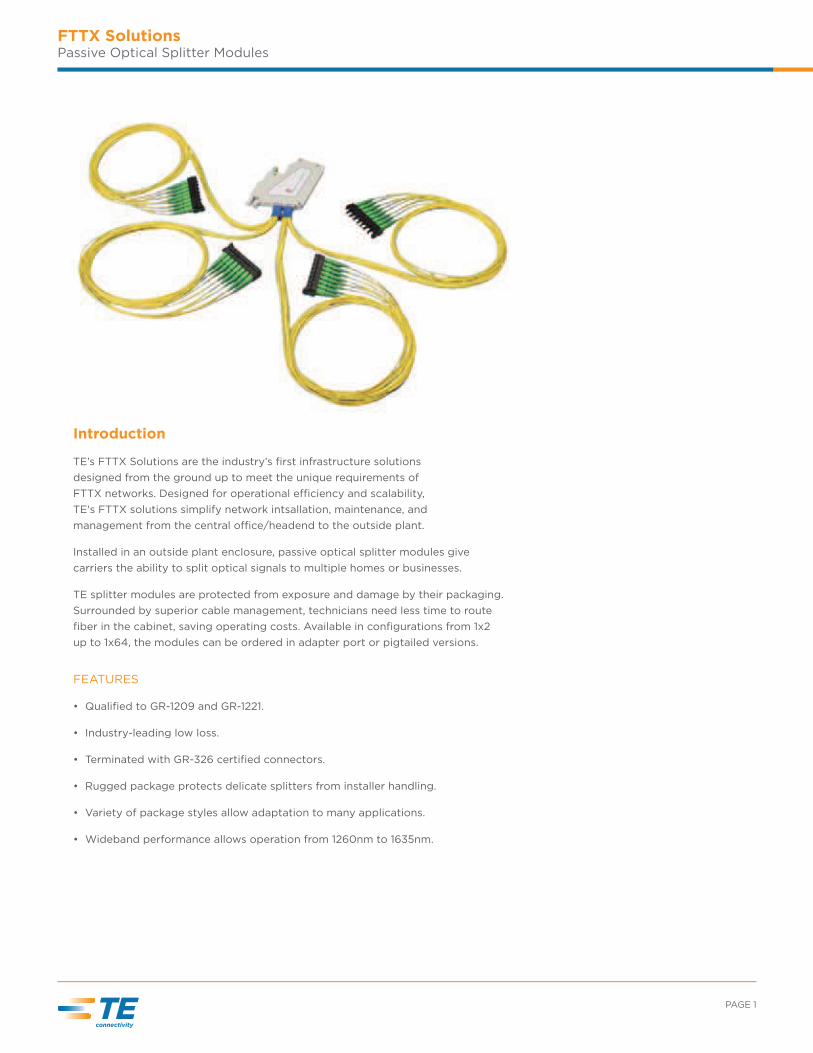
Introduction
TE’s FTTX Solutions are the industry’s first infrastructure solutions
designed from the ground up to meet the unique requirements of
FTTX networks. Designed for operational e_ciency and scalability,
TE's FTTX solutions simplify network intsallation, maintenance, and
management from the central o_ce/headend to the outside plant.
Installed in an outside plant enclosure, passive optical splitter modules give
carriers the ability to split optical signals to multiple homes or businesses.
TE splitter modules are protected from exposure and damage by their packaging.
Surrounded by superior cable management, technicians need less time to route
fiber in the cabinet, saving operating costs. Available in configurations from 1x2
up to 1x64, the modules can be ordered in adapter port or pigtailed versions.
FEATURES
• Qualified to GR-1209 and GR-1221.
• Industry-leading low loss.
• Terminated with GR-326 certified connectors.
• Rugged package protects delicate splitters from installer handling.
• Variety of package styles allow adaptation to many applications.
• Wideband performance allows operation from 1260nm to 1635nm.
BROADBAND NETWORK SOLUTIONS /// FTTX SOLUTIONS PASSIVE OPTICAL SPLITTER MODULES
FTTX SolutionsPassive Optical Splitter Modules
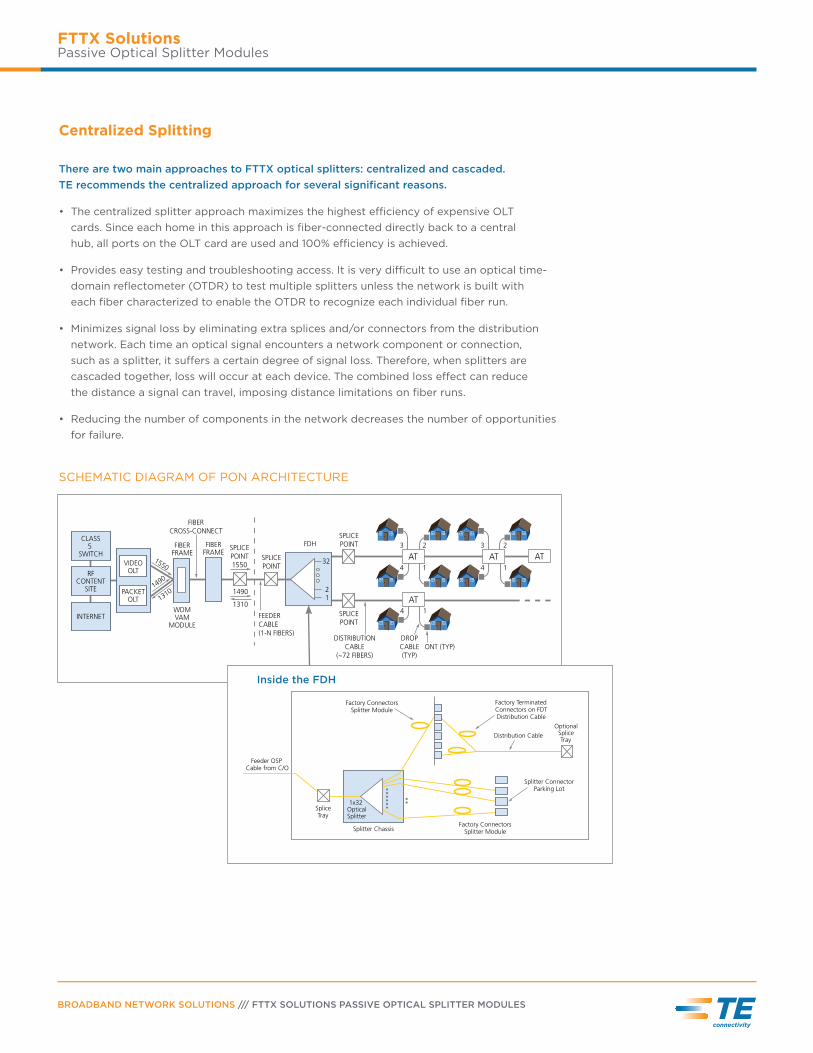
Centralized Splitting
There are two main approaches to FTTX optical splitters: centralized and cascaded.
TE recommends the centralized approach for several significant reasons.
• The centralized splitter approach maximizes the highest e_ciency of expensive OLT
cards. Since each home in this approach is fiber-connected directly back to a central
hub, all ports on the OLT card are used and 100% e_ciency is achieved.
• Provides easy testing and troubleshooting access. It is very di_cult to use an optical time-
domain reflectometer (OTDR) to test multiple splitters unless the network is built with
each fiber characterized to enable the OTDR to recognize each individual fiber run.
• Minimizes signal loss by eliminating extra splices and/or connectors from the distribution
network. Each time an optical signal encounters a network component or connection,
such as a splitter, it susers a certain degree of signal loss. Therefore, when splitters are
cascaded together, loss will occur at each device. The combined loss esect can reduce
the distance a signal can travel, imposing distance limitations on fiber runs.
• Reducing the number of components in the network decreases the number of opportunities
for failure.
SCHEMATIC DIAGRAM OF PON ARCHITECTURE
3
4
2
1
AT
SPLICE
POINT
SPLICE
POINT
DISTRIBUTION
CABLE
(~72 FIBERS)
DROP
CABLE
(TYP)
ONT (TYP)
SPLICE
POINT
FIBERFRAME
SPLICE
POINT
1550
FDH
32
2
1
FEEDER
CABLE
(1-N FIBERS)
3
4
2
1
AT
4 1
AT
AT
1490
1310
FIBERFRAME
FIBER
CROSS-CONNECT
WDMVAM
MODULE
PACKETOLT
VIDEOOLT
CLASS5
SWITCH
RFCONTENT
SITE
INTERNET
1550
13101490
Splitter Chassis
1x32 Optical Splitter
Feeder OSP Cable from C/O
Splice Tray
Optional Splice Tray
Factory Connectors Splitter Module
Factory Terminated Connectors on FDT Distribution Cable
Distribution Cable
Splitter Connector Parking Lot
Factory Connectors Splitter Module
Inside the FDH
PAGE 3
FTTX SolutionsPassive Optical Splitter Modules
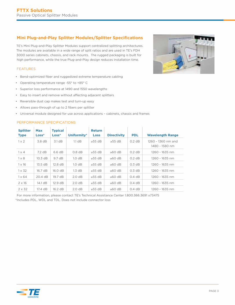
Mini Plug-and-Play Splitter Modules/Splitter Specifications
TE’s Mini Plug-and-Play Splitter Modules support centralized splitting architectures.
The modules are available in a wide range of split ratios and are used in TE’s FDH
3000 series cabinets, chassis, and rack mounts. The rugged packaging is built for
high performance, while the true Plug-and-Play design reduces installation time.
FEATURES
• Bend-optimized fiber and ruggedized extreme temperature cabling
• Operating temperature range -55° to +85° C
• Superior loss performance at 1490 and 1550 wavelengths
• Easy to insert and remove without asecting adjacent splitters
• Reversible dust cap makes test and turn-up easy
• Allows pass-through of up to 2 fibers per splitter
• Universal module designed for use across applications – cabinets, chassis and frames
PERFORMANCE SPECIFICATIONS
Splitter
Type
Max
Loss*
Typical
Loss*
Uniformity*
Return
Loss
Directivity
PDL
Wavelength Range
1 x 2 3.8 dB 3.1 dB 1.1 dB 55 dB 55 dB 0.2 dB 1260 - 1360 nm and
1480 - 1580 nm
1 x 4 7.2 dB 6.6 dB 0.8 dB 55 dB 60 dB 0.2 dB 1260 - 1635 nm
1 x 8 10.3 dB 9.7 dB 1.0 dB 55 dB 60 dB 0.2 dB 1260 - 1635 nm
1 x 16 13.5 dB 12.8 dB 1.0 dB 55 dB 60 dB 0.3 dB 1260 - 1635 nm
1 x 32 16.7 dB 16.0 dB 1.3 dB 55 dB 60 dB 0.3 dB 1260 - 1635 nm
1 x 64 20.4 dB 19.7 dB 2.0 dB 55 dB 60 dB 0.4 dB 1260 - 1635 nm
2 x 16 14.1 dB 12.9 dB 2.0 dB 55 dB 60 dB 0.4 dB 1260 - 1635 nm
2 x 32 17.4 dB 16.2 dB 2.0 dB 55 dB 60 dB 0.4 dB 1260 - 1635 nm
For more information, please contact TE’s Technical Assistance Center 1.800.366.3691 x73475
*Includes PDL, WDL and TDL. Does not include connector loss
BROADBAND NETWORK SOLUTIONS /// FTTX SOLUTIONS PASSIVE OPTICAL SPLITTER MODULES
FTTX SolutionsPassive Optical Splitter Modules
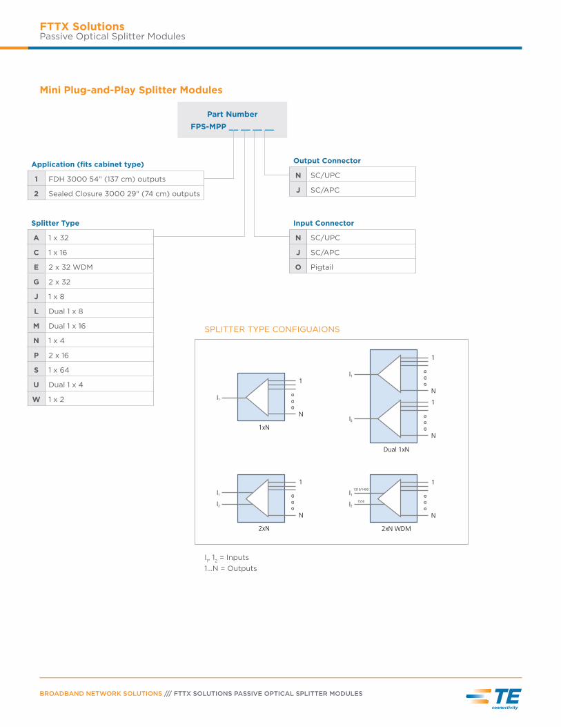
Part Number
FPS-MPP __ __ __ __
1
1xN
I1
N
1
2xN
I2
N
I1
1
2xN WDM
I2
N
I11310/1490
1550
1
Dual 1xN
I1
N
1
I2
N
SPLITTER TYPE CONFIGUAIONS
I1, 1
2 = Inputs
1...N = Outputs
Mini Plug-and-Play Splitter Modules
Application (fits cabinet type)
1 FDH 3000 54" (137 cm) outputs
2 Sealed Closure 3000 29" (74 cm) outputs
Splitter Type
A 1 x 32
C 1 x 16
E 2 x 32 WDM
G 2 x 32
J 1 x 8
L Dual 1 x 8
M Dual 1 x 16
N 1 x 4
P 2 x 16
S 1 x 64
U Dual 1 x 4
W 1 x 2
Output Connector
N SC/UPC
J SC/APC
Input Connector
N SC/UPC
J SC/APC
O Pigtail
PAGE 5
FTTX SolutionsPassive Optical Splitter Modules
NGF Modular Splitter Block
The NGF Modular Splitter Block utilizes TE’s latest splitter packaging technology
and is used in TE’s Next Generation Frame which has unmatched density for fiber
management and signal distribution.
FEATURES
• Designed for use with TE High-Density NGF System.
• Modular design allows up to 48 32-way splitters into one 30" NGF Distribution Frame.
• Splitter inputs and outputs terminated to TE’s patented sliding adapter pack technology.
• NGF splitter block accepts 4 mini plug-and-play splitters (listed below)
ORDERING INFORMATION
Block Style Dimensions Part Number
Left side block mounting 19.35" x 7.20" x 11.80"
(49.14 cm x 18.28 cm x 29.97 cm)
NGF-VSP3-00000L
(For ETSI frame: NGF-VSP3-ETSIOL)
Right side block mounting 19.35" x 7.20" x 11.80"
(49.14 cm x 18.28 cm x 29.97 cm)
NGF-VSP3-00000R
(For ETSI frame: NGF-VSP3-ETSIOR)
Part Number
FPS - MPP 3 __ __ __
Splitter Type
A 1 x 32
C 1 x 16
E 2 x 32 WDM
G 2 x 32
J 1 x 8
L Dual 1 x 8
M Dual 1 x 16
N 1 x 4
P 2 x 16
S 1 x 64
U Dual 1 x 4
W 1 x 2
Output Connector
N SC/UPC
J SC/APC
Input Connector
N SC/UPC (front pigtail)
J SC/APC (front pigtail)
BROADBAND NETWORK SOLUTIONS /// FTTX SOLUTIONS PASSIVE OPTICAL SPLITTER MODULES
FTTX SolutionsPassive Optical Splitter Modules
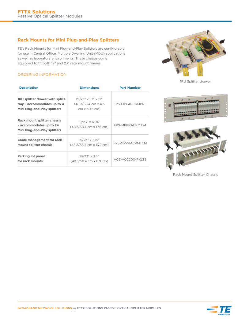
Rack Mounts for Mini Plug-and-Play Splitters
TE’s Rack Mounts for Mini Plug-and-Play Splitters are configurable
for use in Central O_ce, Multiple Dwelling Unit (MDU) applications
as well as laboratory environments. These chassis come
equipped to fit both 19" and 23" rack mount frames.
1RU Splitter drawer
Rack Mount Splitter Chassis
ORDERING INFORMATION
Description Dimensions Part Number
1RU splitter drawer with splice
tray – accommodates up to 4
Mini Plug-and-Play splitters
19/23” x 1.7” x 12”
(48.3/58.4 cm x 4.3
cm x 30.5 cm)
FPS-MPPACCRMPNL
Rack mount splitter chassis
– accommodates up to 24
Mini Plug-and-Play splitters
19/23” x 6.94”
(48.3/58.4 cm x 17.6 cm) FPS-MPPRACKMT24
Cable management for rack
mount splitter chassis
19/23” x 5.19”
(48.3/58.4 cm x 13.2 cm) FPS-MPPRACKMTCM
Parking lot panel
for rack mounts
19/23” x 3.5”
(48.3/58.4 cm x 8.9 cm) ACE-ACC200-PKLT3
PAGE 7
FTTX SolutionsPassive Optical Splitter Modules
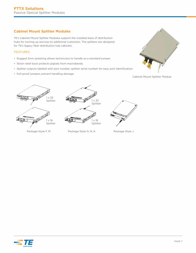
Package Style JPackage Style F, M
1 x 16 Splitter
1 x 32 Splitter
Package Style G, N, K
1 x 16 Splitter
1 x 32 Splitter
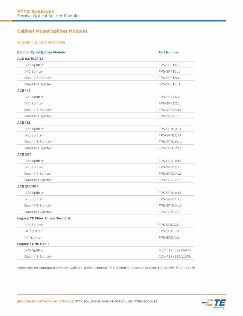
Cabinet Mount Splitter Module
Cabinet Mount Splitter Modules
TE’s Cabinet Mount Splitter Modules support the installed base of distribution
hubs for turning up services to additional customers. The splitters are designed
for TE’s legacy fiber distribution hub cabinets.
FEATURES
• Rugged 2mm jacketing allows technicians to handle as a standard jumper.
• Strain relief boot protects pigtails from macrobends.
• Splitter outputs labeled with port number, splitter serial number for easy port identification.
• Pull-proof jumpers prevent handling damage.
BROADBAND NETWORK SOLUTIONS /// FTTX SOLUTIONS PASSIVE OPTICAL SPLITTER MODULES
FTTX SolutionsPassive Optical Splitter Modules
Cabinet Mount Splitter Modules
ORDERING INFORMATION
Cabinet Type/Splitter Module Part Number
ACE 92/102/132
1x32 Splitter FPS-SPF1AJJ
1x16 Splitter FPS-SPF1CJJ
Dual 1x16 Splitter FPS-SPF1MJJ
Quad 1x8 Splitter FPS-SPF1ZJJ
ACE 142
1x32 Splitter FPS-SPK1AJJ
1x16 Splitter FPS-SPK1CJJ
Dual 1x16 Splitter FPS-SPK1MJJ
Quad 1x8 Splitter FPS-SPK1ZJJ
ACE 152
1x32 Splitter FPS-SPM1AJJ
1x16 Splitter FPS-SPM1CJJ
Dual 1x16 Splitter FPS-SPM1MJJ
Quad 1x8 Splitter FPS-SPM1ZJJ
ACE 204
1x32 Splitter FPS-SPG1AJJ
1x16 Splitter FPS-SPG1CJJ
Dual 1x16 Splitter FPS-SPG1MJJ
Quad 1x8 Splitter FPS-SPG1ZJJ
ACE 214/304
1x32 Splitter FPS-SPN1AJJ
1x16 Splitter FPS-SPN1CJJ
Dual 1x16 Splitter FPS-SPN1MJJ
Quad 1x8 Splitter FPS-SPN1ZJJ
Legacy TE Fiber Access Terminal
1x16 Splitter FPS-SPJ1CJJ
1x8 Splitter FPS-SPJ1JJJ
1x4 Splitter FPS-SPJ1NJJ
Legacy FONS Gen 1
1x32 Splitter OCMF1X4329A09FS
Dual 1x16 Splitter OCMF1X4169A10FS
Other splitter configurations are available, please contact TE’s Technical Assistance Center 800-366-3891 x73475
PAGE 9
FTTX SolutionsPassive Optical Splitter Modules
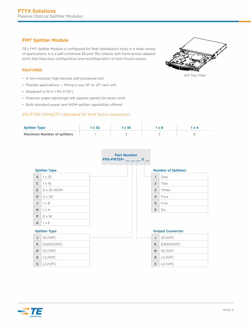
FMT Splitter Module
TE’s FMT Splitter Module is configured for fiber distribution racks in a wide variety
of applications. It is a self contained 36 port 1RU chassis with front-access adapter
ports that help easy configuration and reconfiguration of rack mount setups.
FEATURES
• A non-modular, high-density self-contained unit
• Flexible applications — fitting in any 19" or 23" rack unit
• Designed to fit in 1 RU (1.75")
• Features angle right/angle left adapter panels for strain relief
• Both standard power and WDM splitter capabilities osered
SPLITTER CAPACITY (Standard SC form factor connector)
Splitter Type 1 x 32 1 x 16 1 x 8 1 x 4
Maximum Number of splitters 1 2 3 6
ISO Top View
Part NumberFPS-FMTSP- __ __ __ 0 __
Splitter Type
A 1 x 32
C 1 x 16
E 2 x 32 WDM
G 2 x 32
J 1 x 8
N 1 x 4
P 2 x 16
6 1 x 6
Splitter Type
J SC/APC
K E2000/APC
N SC/UPC
8 LC/APC
S LC/UPC
Number of Splitters
1 One
2 Two
3 Three
4 Four
5 Five
6 Six
Output Connector
J SC/APC
K E2000/APC
N SC/UPC
8 LC/APC
S LC/UPC
BROADBAND NETWORK SOLUTIONS /// FTTX SOLUTIONS PASSIVE OPTICAL SPLITTER MODULES
FTTX SolutionsPassive Optical Splitter Modules
Part Number
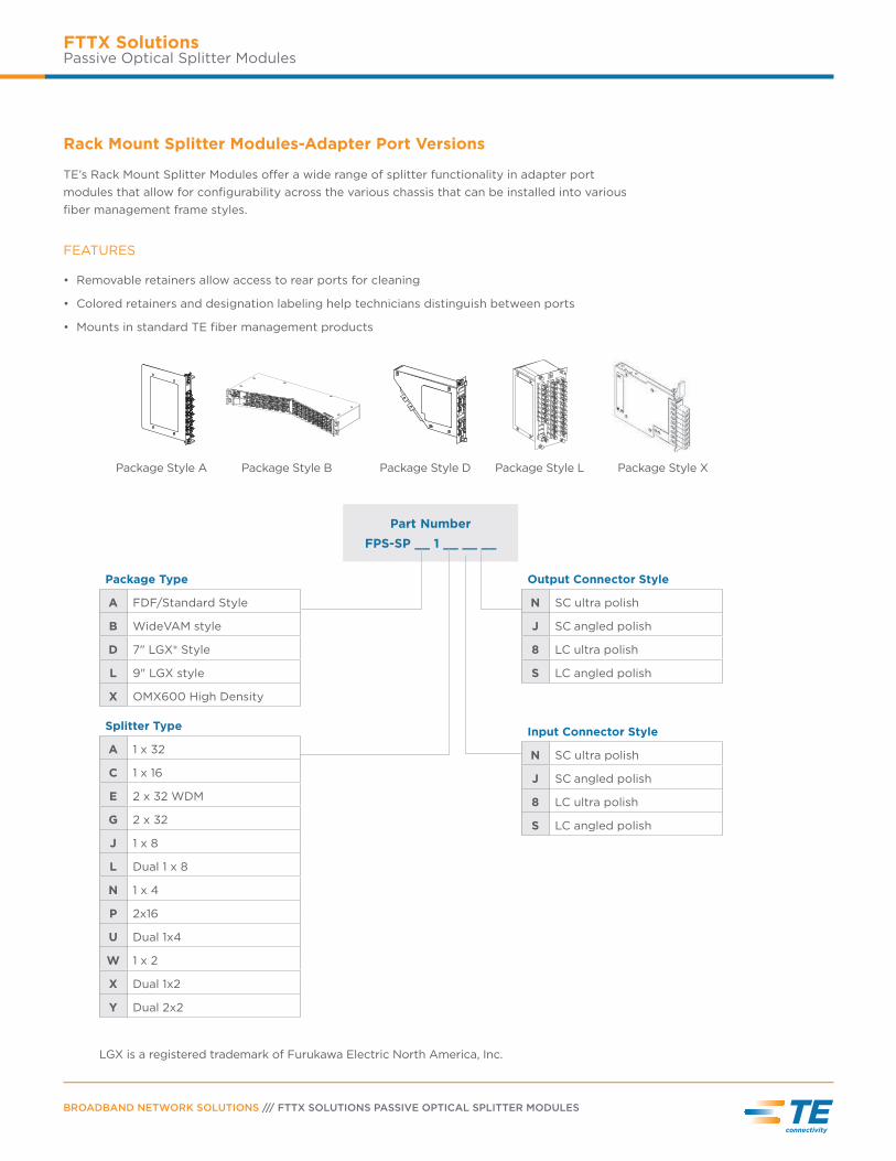
FPS-SP __ 1 __ __ __
Package Style DPackage Style A Package Style LPackage Style B Package Style X
Rack Mount Splitter Modules-Adapter Port Versions
TE’s Rack Mount Splitter Modules oser a wide range of splitter functionality in adapter port
modules that allow for configurability across the various chassis that can be installed into various
fiber management frame styles.
FEATURES
• Removable retainers allow access to rear ports for cleaning
• Colored retainers and designation labeling help technicians distinguish between ports
• Mounts in standard TE fiber management products
LGX is a registered trademark of Furukawa Electric North America, Inc.
Package Type
A FDF/Standard Style
B WideVAM style
D 7" LGX® Style
L 9" LGX style
X OMX600 High Density
Output Connector Style
N SC ultra polish
J SC angled polish
8 LC ultra polish
S LC angled polish
Input Connector Style
N SC ultra polish
J SC angled polish
8 LC ultra polish
S LC angled polish
Splitter Type
A 1 x 32
C 1 x 16
E 2 x 32 WDM
G 2 x 32
J 1 x 8
L Dual 1 x 8
N 1 x 4
P 2x16
U Dual 1x4
W 1 x 2
X Dual 1x2
Y Dual 2x2
PAGE 11
FTTX SolutionsPassive Optical Splitter Modules
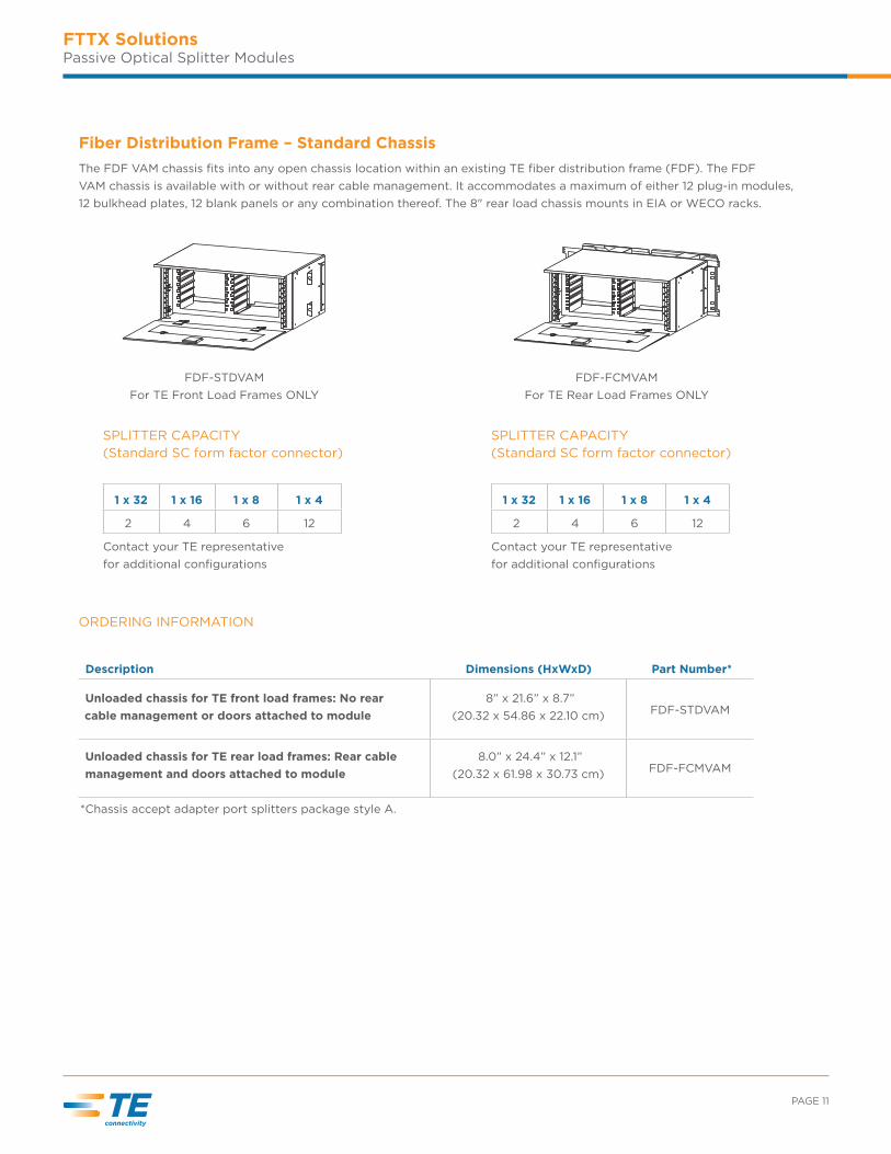
Fiber Distribution Frame – Standard Chassis
The FDF VAM chassis fits into any open chassis location within an existing TE fiber distribution frame (FDF). The FDF
VAM chassis is available with or without rear cable management. It accommodates a maximum of either 12 plug-in modules,
12 bulkhead plates, 12 blank panels or any combination thereof. The 8" rear load chassis mounts in EIA or WECO racks.
ORDERING INFORMATION
Description Dimensions (HxWxD) Part Number*
Unloaded chassis for TE front load frames: No rear
cable management or doors attached to module
8” x 21.6” x 8.7”
(20.32 x 54.86 x 22.10 cm) FDF-STDVAM
Unloaded chassis for TE rear load frames: Rear cable
management and doors attached to module
8.0” x 24.4” x 12.1”
(20.32 x 61.98 x 30.73 cm) FDF-FCMVAM
*Chassis accept adapter port splitters package style A.
FDF-STDVAM
For TE Front Load Frames ONLY
FDF-FCMVAM
For TE Rear Load Frames ONLY
SPLITTER CAPACITY
(Standard SC form factor connector)
1 x 32 1 x 16 1 x 8 1 x 4
2 4 6 12
Contact your TE representative
for additional configurations
SPLITTER CAPACITY
(Standard SC form factor connector)
1 x 32 1 x 16 1 x 8 1 x 4
2 4 6 12
Contact your TE representative
for additional configurations
BROADBAND NETWORK SOLUTIONS /// FTTX SOLUTIONS PASSIVE OPTICAL SPLITTER MODULES
FTTX SolutionsPassive Optical Splitter Modules
FTTX SolutionsPassive Optical Splitter Modules
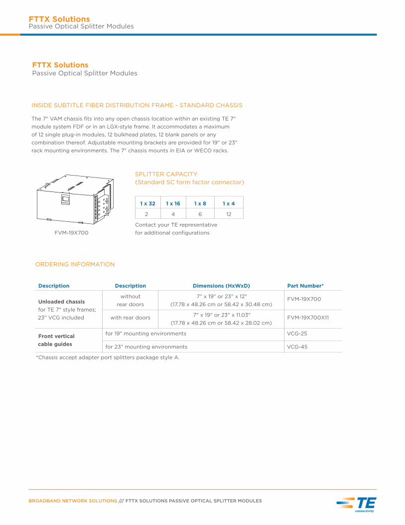
INSIDE SUBTITLE FIBER DISTRIBUTION FRAME - STANDARD CHASSIS
The 7" VAM chassis fits into any open chassis location within an existing TE 7"
module system FDF or in an LGX-style frame. It accommodates a maximum
of 12 single plug-in modules, 12 bulkhead plates, 12 blank panels or any
combination thereof. Adjustable mounting brackets are provided for 19" or 23"
rack mounting environments. The 7" chassis mounts in EIA or WECO racks.
FVM-19X700
SPLITTER CAPACITY
(Standard SC form factor connector)
1 x 32 1 x 16 1 x 8 1 x 4
2 4 6 12
Contact your TE representative
for additional configurations
ORDERING INFORMATION
Description Description Dimensions (HxWxD) Part Number*
Unloaded chassis
for TE 7" style frames;
23" VCG included
without
rear doors
7" x 19" or 23" x 12"
(17.78 x 48.26 cm or 58.42 x 30.48 cm)FVM-19X700
with rear doors 7" x 19" or 23" x 11.03"
(17.78 x 48.26 cm or 58.42 x 28.02 cm)FVM-19X700X11
Front vertical
cable guides
for 19" mounting environments VCG-25
for 23" mounting environments VCG-45
*Chassis accept adapter port splitters package style A.
PAGE 13
FTTX SolutionsPassive Optical Splitter Modules
FTTX SolutionsPassive Optical Splitter Modules
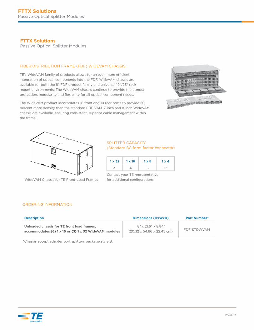
FIBER DISTRIBUTION FRAME (FDF) WIDEVAM CHASSIS
TE’s WideVAM family of products allows for an even more e_cient
integration of optical components into the FDF. WideVAM chassis are
available for both the 8" FDF product family and universal 19"/23" rack
mount environments. The WideVAM chassis continue to provide the utmost
protection, modularity and flexibility for all optical component needs.
The WideVAM product incorporates 18 front and 10 rear ports to provide 50
percent more density than the standard FDF VAM. 7-inch and 8-inch WideVAM
chassis are available, ensuring consistent, superior cable management within
the frame.
WideVAM Chassis for TE Front-Load Frames
SPLITTER CAPACITY
(Standard SC form factor connector)
1 x 32 1 x 16 1 x 8 1 x 4
2 4 6 12
Contact your TE representative
for additional configurations
ORDERING INFORMATION
Description Dimensions (HxWxD) Part Number*
Unloaded chassis for TE front load frames;
accommodates (6) 1 x 16 or (3) 1 x 32 WideVAM modules
8” x 21.6” x 8.84”
(20.32 x 54.86 x 22.45 cm) FDF-STDWVAM
*Chassis accept adapter port splitters package style B.
BROADBAND NETWORK SOLUTIONS /// FTTX SOLUTIONS PASSIVE OPTICAL SPLITTER MODULES
FTTX SolutionsPassive Optical Splitter Modules
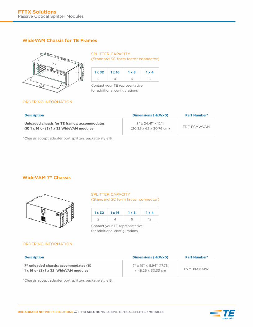
WideVAM 7" Chassis
WideVAM Chassis for TE Frames
SPLITTER CAPACITY
(Standard SC form factor connector)
1 x 32 1 x 16 1 x 8 1 x 4
2 4 6 12
Contact your TE representative
for additional configurations
SPLITTER CAPACITY
(Standard SC form factor connector)
1 x 32 1 x 16 1 x 8 1 x 4
2 4 6 12
Contact your TE representative
for additional configurations
ORDERING INFORMATION
Description Dimensions (HxWxD) Part Number*
Unloaded chassis for TE frames; accommodates
(6) 1 x 16 or (3) 1 x 32 WideVAM modules
8" x 24.41" x 12.11"
(20.32 x 62 x 30.76 cm) FDF-FCMWVAM
*Chassis accept adapter port splitters package style B.
ORDERING INFORMATION
Description Dimensions (HxWxD) Part Number*
7" unloaded chassis; accommodates (6)
1 x 16 or (3) 1 x 32 WideVAM modules
7" x 19" x 11.94" (17.78
x 48.26 x 30.33 cm FVM-19X700W
*Chassis accept adapter port splitters package style B.
PAGE 15
FTTX SolutionsPassive Optical Splitter Modules
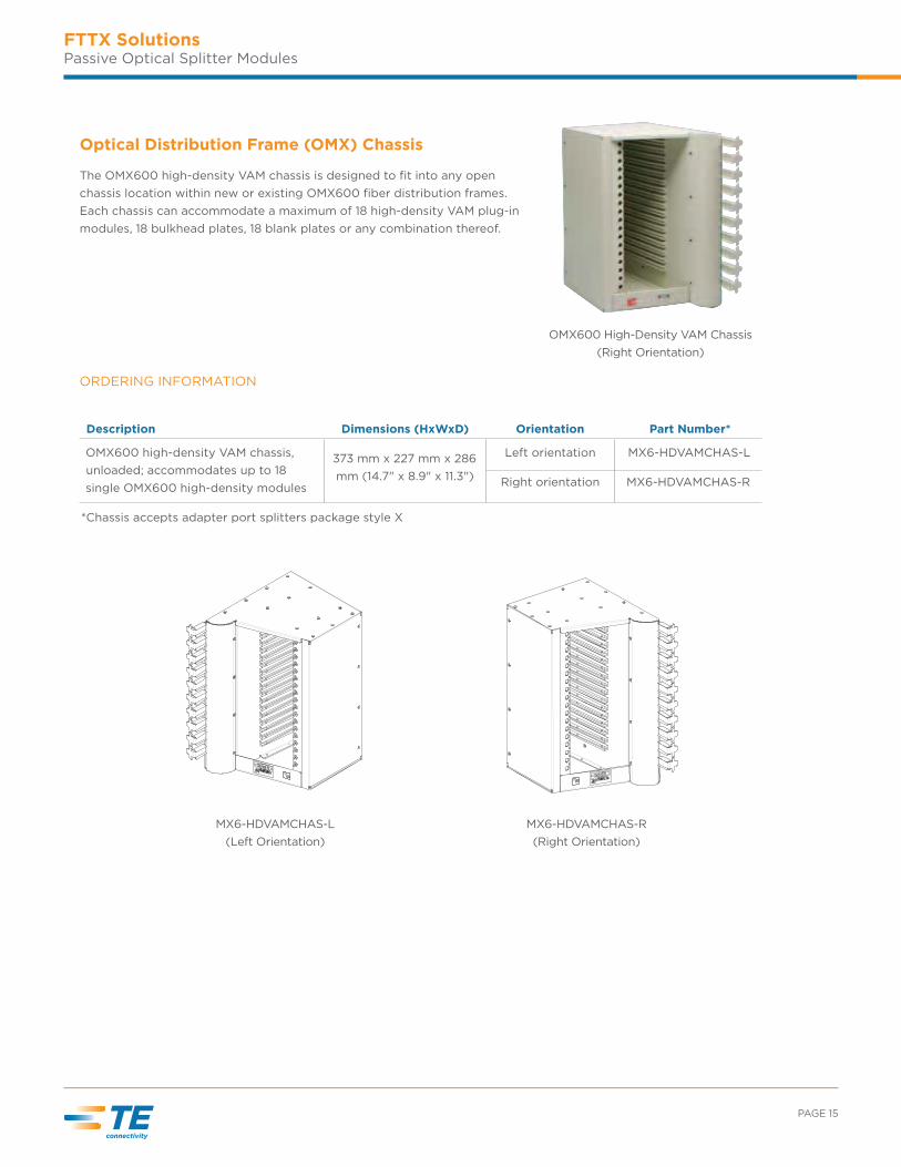
Optical Distribution Frame (OMX) Chassis
The OMX600 high-density VAM chassis is designed to fit into any open
chassis location within new or existing OMX600 fiber distribution frames.
Each chassis can accommodate a maximum of 18 high-density VAM plug-in
modules, 18 bulkhead plates, 18 blank plates or any combination thereof.
MX6-HDVAMCHAS-L
(Left Orientation)
MX6-HDVAMCHAS-R
(Right Orientation)
OMX600 High-Density VAM Chassis
(Right Orientation)
ORDERING INFORMATION
Description Dimensions (HxWxD) Orientation Part Number*
OMX600 high-density VAM chassis,
unloaded; accommodates up to 18
single OMX600 high-density modules
373 mm x 227 mm x 286
mm (14.7" x 8.9" x 11.3")
Left orientation MX6-HDVAMCHAS-L
Right orientation MX6-HDVAMCHAS-R
*Chassis accepts adapter port splitters package style X
BROADBAND NETWORK SOLUTIONS /// FTTX SOLUTIONS PASSIVE OPTICAL SPLITTER MODULES
FTTX SolutionsPassive Optical Splitter Modules
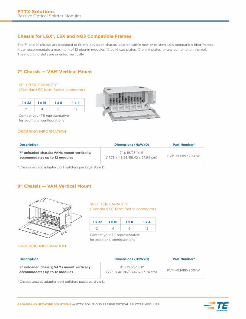
Chassis for LGX®, LSX and NG3 Compatible Frames
The 7" and 9" chassis are designed to fit into any open chassis location within new or existing LGX-compatible fiber frames.
It can accommodate a maximum of 12 plug-in modules, 12 bulkhead plates, 12 blank plates, or any combination thereof.
The mounting slots are oriented vertically.
7" Chassis — VAM Vertical Mount
9" Chassis — VAM Vertical Mount
SPLITTER CAPACITY
(Standard SC form factor connector)
1 x 32 1 x 16 1 x 8 1 x 4
2 4 6 12
Contact your TE representative
for additional configurations
SPLITTER CAPACITY
(Standard SC form factor connector)
1 x 32 1 x 16 1 x 8 1 x 4
2 4 6 12
Contact your TE representative
for additional configurations
ORDERING INFORMATION
Description Dimensions (HxWxD) Part Number*
7" unloaded chassis; VAMs mount vertically;
accommodates up to 12 modules
7" x 19/23" x 11"
(17.78 x 48.26/58.42 x 27.94 cm) FVM-VLM19X700-W
*Chassis accept adapter port splitters package style D.
ORDERING INFORMATION
Description Dimensions (HxWxD) Part Number*
9" unloaded chassis; VAMs mount vertically;
accommodates up to 12 modules
9" x 19/23" x 11"
(22.9 x 48.26/58.42 x 27.94 cm) FVM-VLM19X900-W
*Chassis accept adapter port splitters package style L.

Contact us
P.O. Box 1101
Minneapolis, Minnesota
USA 55440-1101
Tel: 1-800-366-3891 x73000
1-952-917-3000
Fax: 1-952-917-3237
www.te.com/TelecomNetworks
CATALOG
BROADBAND NETWORK SOLUTIONS /// FTTX SOLUTIONS PASSIVE OPTICAL SPLITTER MODULES
te.comTE Connectivity, TE Connectivity (logo) and Every Connection Counts are trademarks. All other logos, products
and/or company names referred to herein might be trademarks of their respective owners.
The information given herein, including drawings, illustrations and schematics which are intended for illustration
purposes only, is believed to be reliable. However, TE Connectivity makes no warranties as to its accuracy or
completeness and disclaims any liability in connection with its use. TE Connectivity‘s obligations shall only be
as set forth in TE Connectivity‘s Standard Terms and Conditions of Sale for this product and in no case will TE
Connectivity be liable for any incidental, indirect or consequential damages arising out of the sale, resale, use
or misuse of the product. Users of TE Connectivity products should make their own evaluation to determine the
suitability of each such product for the specific application.
© 2014 TE Connectivity Ltd. family of companies All Rights Reserved.
102902AE 8/14 Revision