Embed Size (px)
Citation preview

Pantone 419C
2013 Owner's Manual for Maintenance and SafetyRead this manual carefully.
It contains important safety information.

1
2
The following are registered trademarks of POLARIS Industries Inc.:
Copyright 2012 POLARIS Sales Inc. All information contained within this publication is based on the latest product information at the time of publication. Due to constant improvements in the design and quality of produc-tion components, some minor discrepancies may result between the actual vehicle and the information presented in this publication. Depictions and/or procedures in this publication are intended for reference use only. No liabil-ity can be accepted for omissions or inaccuracies. Any reprinting or reuse of the depictions and/or procedures contained within, whether whole or in part, is expressly prohibited.Global Electric Motorcars® is a division of POLARIS®.Printed in U.S.A.2013 GEM Owner’s ManualP/N 9924250
POLARIS® VICTORY® Global Electric Motorcars®RANGER® INDIAN® GEM® e6®

3
TABLE OF CONTENTSIntroduction. . . . . . . . . . . . . . . . . . . . . . . . . . . . . . . . . . . . . . . . . . . . . . . . . 6Safety. . . . . . . . . . . . . . . . . . . . . . . . . . . . . . . . . . . . . . . . . . . . . . . . . . . . . 12Features and Controls . . . . . . . . . . . . . . . . . . . . . . . . . . . . . . . . . . . . . . . 32Operation. . . . . . . . . . . . . . . . . . . . . . . . . . . . . . . . . . . . . . . . . . . . . . . . . . 86Maintenance . . . . . . . . . . . . . . . . . . . . . . . . . . . . . . . . . . . . . . . . . . . . . . . 96Specifications . . . . . . . . . . . . . . . . . . . . . . . . . . . . . . . . . . . . . . . . . . . . . 134Warranty . . . . . . . . . . . . . . . . . . . . . . . . . . . . . . . . . . . . . . . . . . . . . . . . . 140Maintenance Log . . . . . . . . . . . . . . . . . . . . . . . . . . . . . . . . . . . . . . . . . . 147Index . . . . . . . . . . . . . . . . . . . . . . . . . . . . . . . . . . . . . . . . . . . . . . . . . . . . 151

4
WELCOMEThank you for purchasing a GEM by POLARIS, and welcome to our world-wide POLARIS family of recreational and utility vehicle owners. We believe POLARIS sets a standard of excellence for all recreational and utility vehicles manufactured in the world today. With our many years of experience in design and manufacturing, we proudly bring you only the finest of vehicles:• Snowmobiles• All-terrain vehicles (ATVs)• RANGER® utility vehicles• Low emission vehicles (LEVs)• VICTORY® motorcycles• INDIAN® motorcycles• GEM® vehicles
5
WELCOMEFor safe and enjoyable operation of your vehicle, be sure to follow the instructions and rec-ommendations in this owner’s manual. Your manual contains instructions for minor mainte-nance, but information about major repairs is outlined in the GEM Service Manual and should be performed only by an authorized GEM dealer technician. If questions arise after reading the manual, please contact GEM customer service. Be pre-pared to provide your Vehicle Identification Number (VIN) and date of purchase.Your authorized GEM dealer knows your vehicle best and is interested in your total satisfac-tion. Be sure to return to your dealership for all of your service needs during, and after, the warranty period.
GEM Customer ServicePhone: 855-RIDEGEM (855-743-3436)Web: www.gemcar.com
6
INTRODUCTIONThis vehicle complies with the U.S. Department of Transportation National Highway Traffic Safety Administration (NHTSA) low-speed vehicle regulations and can be operated on many streets posted with low speed limits. Please familiarize yourself with all laws and regulations concerning the operation of the vehicle in your area. This manual applies to the following GEM vehicles: • GEM e2 (two-passenger)• GEM e4 (four-passenger)• GEM eS (two-passenger short-bed)• GEM eL (two-passenger long-bed)• GEM eL XD (two-passenger extra duty long-bed)• GEM e6® (six-passenger)
7
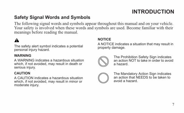
INTRODUCTIONSafety Signal Words and SymbolsThe following signal words and symbols appear throughout this manual and on your vehicle. Your safety is involved when these words and symbols are used. Become familiar with their meanings before reading the manual.
The safety alert symbol indicates a potential personal injury hazard.
WARNINGA WARNING indicates a hazardous situation which, if not avoided, may result in death or serious injury.
CAUTIONA CAUTION indicates a hazardous situation which, if not avoided, may result in minor or moderate injury.
NOTICEA NOTICE indicates a situation that may result in property damage.
The Prohibition Safety Sign indicates an action NOT to take in order to avoid a hazard.
The Mandatory Action Sign indicates an action that NEEDS to be taken to avoid a hazard.
8
INTRODUCTION
Failure to follow the warnings contained in this manual can result in severe injury or death.Special precautions must be followed when owning and operating a battery-powered vehicle. This vehicle is not a toy and can be hazardous to operate. This vehicle handles differently than other vehicles. A collision or rollover can occur quickly, even during routine maneuvers, if you fail to take proper precautions.
• Read this owner’s manual. Understand all safety warnings, precautions and operating procedures before operating the vehicle. Keep this manual with the vehicle.
• This vehicle is an ADULT VEHICLE ONLY. NEVER operate this vehicle if you are under age 16 and NEVER operate without a valid driver’s license.
• Never permit a guest to operate this vehicle unless the guest has read this manual and all product labels.
• Operate this vehicle only on public or private roads where speed limits are appropriate for low speed vehicles. Be familiar with motor vehicle laws in your area of operation. Do not operate this vehicle in situations where it could become an obstacle or an annoyance for faster-moving traffic.
WARNING
9
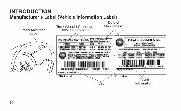
INTRODUCTIONManufacturer’s Label (Vehicle Information Label)Record your vehicle's identification numbers and key number in the spaces provided on page 11.The Vehicle Identification Number (VIN) is on the manufacturer’s label, located on the left rear section of the roof panel. The VIN indicates the model year, model type and serial num-ber of your vehicle. The manufacturer’s label also contains the Gross Vehicle Weight Rating (GVWR) and Gross Axle Weight Rating (GAWR) information for your vehicle. Never exceed the GVWR or the GAWR. See page 22.To order an extra or replacement key for your vehicle, please contact GEM customer service. See page 5. Be prepared to provide your key number and VIN.
10
INTRODUCTIONManufacturer’s Label (Vehicle Information Label)
Manufacturer’s Label
VINGVWR
Information
Tire / Wheel InformationGAWR Information
Date of Manufacture
USA Label EU Label
11
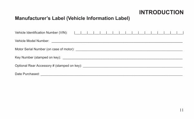
INTRODUCTIONManufacturer’s Label (Vehicle Information Label)
Vehicle Identification Number (VIN): |___|___|___|___|___|___|___|___|___|___|___|___|___|___|___|___|___|
Vehicle Model Number: _______________________________________________________________________
Motor Serial Number (on case of motor): __________________________________________________________
Key Number (stamped on key): _________________________________________________________________
Optional Rear Accessory # (stamped on key): ______________________________________________________
Date Purchased: _____________________________________________________________________________
12
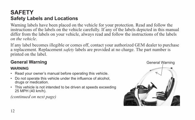
SAFETYSafety Labels and LocationsWarning labels have been placed on the vehicle for your protection. Read and follow the instructions of the labels on the vehicle carefully. If any of the labels depicted in this manual differ from the labels on your vehicle, always read and follow the instructions of the labels on the vehicle.If any label becomes illegible or comes off, contact your authorized GEM dealer to purchase a replacement. Replacement safety labels are provided at no charge. The part number is printed on the label.
General WarningWARNING• Read your owner’s manual before operating this vehicle.• Do not operate this vehicle under the influence of alcohol,
drugs or medication.• This vehicle is not intended to be driven at speeds exceeding
25 MPH (40 km/h).(continued on next page)
General Warning
13
SAFETYSafety Labels and LocationsGeneral Warning• Although most states prohibit this vehicle from operating on streets having posted speed limits of
more than 35 MPH (56 km/h), state and local rules may vary. Check with your local law enforcement (city and state officials) for variations in your area.
• Never exceed the passenger and cargo limits of this vehicle.• Do not start or operate vehicle until all occupants are seated with seat belts fastened.• Avoid sharp turns an inclines and at high speeds (may cause rollover).• Reduce speed on wet and slippery surfaces and in turns.• Do not leave children unattended in vehicle.• Set handbrake before leaving the vehicle.• Remove key when leaving vehicle unattended.• Stop vehicle before reversing direction.• Be aware of small children and objects behind you before reversing direction.• ALWAYS DRIVE SAFELY. FAILURE TO FOLLOW THESE WARNINGS COULD RESULT IN
SERIOUS OR FATAL INJURY.
14
SAFETYSafety Labels and LocationsDoor/Seat Belt WarningThis label is located near the lower edge of the window on the driver’s side door on models equipped with doors.WARNINGThe doors on this vehicle are designed only for protection against the elements. Do not rely on the doors to contain occupants within the vehicle or to protect against injury during an accident.WEAR SEAT BELTS AT ALL TIMES.
15
SAFETYSafety Labels and LocationsHigh Voltage WarningHigh voltage warning labels are located in two places on your vehicle: near the battery com-partment and under the hood near the motor controller.
WARNINGHIGH VOLTAGEYou could be seriously or fatally injured by electric shock if you attempt to open, repair, test, inspect or adjust. Only qualified technicians should open and service. Consult service manual.

16
SAFETYSafety Labels and LocationsCargo WarningsCargo warning labels are located in the beds of GEM eL and GEM eL XD models.CARGO WARNING (eL)• Maximum cargo capacity of this bed should never exceed 700 lbs. (317.5 kg).• Distribute weight equally over axle.• No passengers permitted.• Abuse or noncompliance will void warranty.
CARGO WARNING (eL XD)• Maximum cargo capacity of this bed should never exceed 1100 lbs. (499 kg).• Distribute weight equally over axle.• No passengers permitted.• Abuse or noncompliance will void warranty.
17
SAFETYOperator Safety
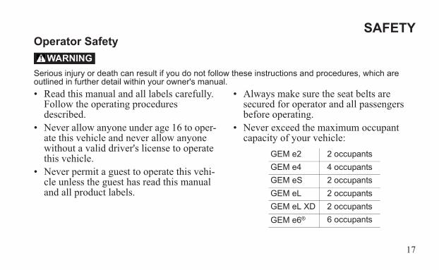
Serious injury or death can result if you do not follow these instructions and procedures, which are outlined in further detail within your owner's manual.• Read this manual and all labels carefully.
Follow the operating procedures described.
• Never allow anyone under age 16 to oper-ate this vehicle and never allow anyone without a valid driver's license to operate this vehicle.
• Never permit a guest to operate this vehi-cle unless the guest has read this manual and all product labels.
• Always make sure the seat belts are secured for operator and all passengers before operating.
• Never exceed the maximum occupant capacity of your vehicle:
WARNING
GEM e2 2 occupantsGEM e4 4 occupantsGEM eS 2 occupantsGEM eL 2 occupantsGEM eL XD 2 occupantsGEM e6® 6 occupants
18
SAFETYOperator Safety• Never exceed the gross vehicle weight
rating (GVWR) of your vehicle.• The cab frame is not designed or intended
to provide rollover protection. Avoid situ-ations that could result in a rollover.
• Always be sure there are no obstacles or people behind your vehicle when operat-ing in reverse. When it's safe to proceed in reverse, move slowly. Avoid turning at sharp angles in reverse.
• Always use the proper size and type of tires and always maintain proper tire pressure as specified in this manual and on safety labels.
• Never modify this vehicle through improper installation or use of accesso-ries.
19
SAFETYOperator Safety• Never carry loads on the roof of the vehi-
cle. Never exceed the stated load capacity for this vehicle. Cargo should be properly distributed and securely attached. Reduce speed and follow the instructions on cargo warning labels for hauling cargo. Allow a greater distance for braking.
• Always set the park brake and remove the key when leaving the vehicle unattended.
• The voltage in the battery pack is suffi-cient to cause death by electrocution. With the exception of battery inspections and refilling the water in flooded type batteries, never attempt to perform ser-vice on the electric drive system, includ-ing the battery pack, unless you are properly trained to work on electrical sys-tems.
20
SAFETYOperator Safety• Do not carry a passenger until you have at
least two hours of driving experience with this vehicle.
• Always keep arms and legs inside the cab frame while the vehicle is in motion.
• Always keep both hands on the steering wheel and both feet on the floorboards of the vehicle during operation.
• Never consume alcohol or drugs before or while operating this vehicle.
• Never operate at excessive speeds. Always travel at a speed proper for the traffic, visibility and operating conditions, and your experience.
• Never attempt jumps, doughnuts or other stunts.
• Always inspect your vehicle each time you use it to make sure it's in safe operating condition. Always follow the inspection and maintenance procedures and schedules described in this manual.
21
SAFETYOperator Safety• Never operate on excessively rough, slip-
pery or loose terrain.• Always follow proper procedures for
turning. Practice turning at slow speeds before attempting to turn at faster speeds. Never turn at excessive speeds.
• Always have this vehicle checked by an authorized GEM dealer if it has been involved in an accident.
• Always be alert for obstacles when oper-ating this vehicle. Never attempt to oper-ate over obstacles.
• Always be careful of skidding or sliding. On slippery surfaces such as ice, travel slowly and exercise caution to reduce the chance of skidding or sliding out of con-trol.
• Never operate this vehicle on steep hills.
22
SAFETYOperator SafetyGross Vehicle Weight Rating (GVWR)WARNING! Exceeding the gross vehicle weight rating of your vehicle can reduce stability and handling and could cause loss of control. NEVER exceed the GVWR of your vehicle.The maximum payload capacity of your vehicle is the maximum weight you may add to your vehicle without exceeding the GVWR. This capacity is determined by calculating the difference between your vehicle’s GVWR and wet weight. Refer to the specification section of this manual or the Manufacturer’s Label on the vehicle for model-specific information.
23
SAFETYOperator SafetyGross Vehicle Weight Rating (GVWR)When determining the weight you will be adding to your vehicle, and to ensure you do not exceed the maximum payload capacity, include the following:• operator body weight• passenger body weight• weight of all occupants’ apparel and items in or on apparel• weight of any options or accessories and their contents• weight of any additional cargo on the vehicle
24
SAFETYOperator SafetyEquipment ModificationsNever install any equipment or make vehicle modifications to increase the speed or power of the vehicle. Any modifications to the original equipment of the vehicle create a substantial safety hazard and increase the risk of bodily injury. The warranty on your vehicle is termi-nated if any equipment has been added to the vehicle, or if any modifications have been made to the vehicle, that increase its speed or power.The addition of certain accessories, including (but not limited to) mowers, blades, tires, sprayers, or large racks, may change the handling characteristics of the vehicle. Use only GEM-approved accessories, and familiarize yourself with their function and effect on the vehicle.
25
SAFETYOperator Safety
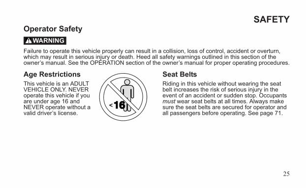
Failure to operate this vehicle properly can result in a collision, loss of control, accident or overturn, which may result in serious injury or death. Heed all safety warnings outlined in this section of the owner’s manual. See the OPERATION section of the owner’s manual for proper operating procedures.
Age RestrictionsThis vehicle is an ADULT VEHICLE ONLY. NEVER operate this vehicle if you are under age 16 and NEVER operate without a valid driver’s license.
Seat BeltsRiding in this vehicle without wearing the seat belt increases the risk of serious injury in the event of an accident or sudden stop. Occupants must wear seat belts at all times. Always make sure the seat belts are secured for operator and all passengers before operating. See page 71.
WARNING
26
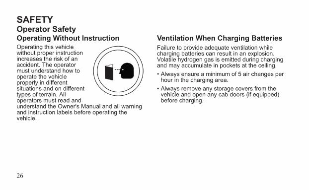
SAFETYOperator SafetyOperating Without InstructionOperating this vehicle without proper instruction increases the risk of an accident. The operator must understand how to operate the vehicle properly in different situations and on different types of terrain. All operators must read and understand the Owner's Manual and all warning and instruction labels before operating the vehicle.
Ventilation When Charging BatteriesFailure to provide adequate ventilation while charging batteries can result in an explosion. Volatile hydrogen gas is emitted during charging and may accumulate in pockets at the ceiling.• Always ensure a minimum of 5 air changes per
hour in the charging area. • Always remove any storage covers from the
vehicle and open any cab doors (if equipped) before charging.
27
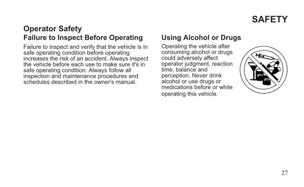
SAFETYOperator SafetyFailure to Inspect Before OperatingFailure to inspect and verify that the vehicle is in safe operating condition before operating increases the risk of an accident. Always inspect the vehicle before each use to make sure it's in safe operating condition. Always follow all inspection and maintenance procedures and schedules described in the owner's manual.
Using Alcohol or DrugsOperating the vehicle after consuming alcohol or drugs could adversely affect operator judgment, reaction time, balance and perception. Never drink alcohol or use drugs or medications before or while operating this vehicle.
28
SAFETYOperator SafetyOperating a Damaged VehicleOperating a damaged vehicle can result in an accident. After any overturn or accident, have your authorized GEM dealer inspect the entire machine for possible damage, including (but not limited to) brakes, accelerator, steering system and electrical system.
Operating at Excessive SpeedsOperating this vehicle at excessive speeds increases the operator's risk of losing control. Always operate at a speed that's appropriate for the traffic, the visibility and operating conditions, your skills and your passengers’ skills.
Exhibition DrivingExhibition driving increases the risk of an accident or overturn. Never attempt wheelies, jumps, doughnuts or other stunts. Avoid exhibition driving.
29
SAFETYOperator SafetyTurning ImproperlyTurning improperly could cause loss of traction, loss of control, accident or overturn. Always follow proper procedures for turning. Never turn abruptly or at sharp angles. Never turn at high speeds. Practice turning at slow speeds before attempting to turn at faster speeds.
Vehicle RolloverVehicle rollover could cause serious injury or death. The cab frame is not designed or intended to provide rollover protection. Always make sure the seat belts are secured for operator and all passengers before operating. Avoid situations that could result in a rollover. Avoid sharp turns and abrupt steering maneuvers.
Carrying CargoCarrying loads on the roof could damage the roof and affect vehicle handling, which could result in an accident or overturn. Never carry loads on the roof of the vehicle.
30
SAFETYOperator SafetyImproper Tire MaintenanceOperating this vehicle with improper tires or with improper or uneven tire pressure could cause loss of control or accident. Always use the size and type of tires specified for your vehicle. Always maintain proper tire pressure as described in the owner's manual and on safety labels.
Unauthorized Use of the VehicleLeaving the keys in the vehicle can lead to unauthorized use of the vehicle, which could result in an accident or overturn. Always remove the key when the vehicle is not in use.
Hot Drive SystemsThe motor and controller are very hot during and after use of the vehicle. Hot components can cause burns and fire. Do not touch hot drive system components. Always keep combustible materials away from the drive system.
31
SAFETYOperator SafetyPrecautions During MaintenanceWARNING! The voltage in the battery pack is sufficient to cause death by electrocution. With the exception of battery inspections and refilling the water in flooded type batteries, never attempt to perform service on the electric drive system, including the battery pack, unless you are properly trained to work on electrical systems. WARNING! Do not work in or near the battery compartment or on any other electrical component of the vehicle while charging the batteries. Always turn off the main disconnect switch before servicing or unplugging any electrical components. See page 52.
Always follow all safety instructions in the maintenance portion of this owner’s manual, as well as the following:• Make sure the vehicle is properly immobilized
before beginning any maintenance.• Always block the chassis securely before work-
ing under the vehicle.• Turn the key off and remove it from the vehicle.• Insulate any tools used within the battery area
to prevent sparks or battery explosion caused by shorting the battery terminals or wiring. Remove the batteries, or cover the exposed ter-minals with an insulating material.
FOR MORE INFORMATION ABOUT SAFETY PLEASE CONTACT GEM CUSTOMER SERVICE.
See page 5.
32
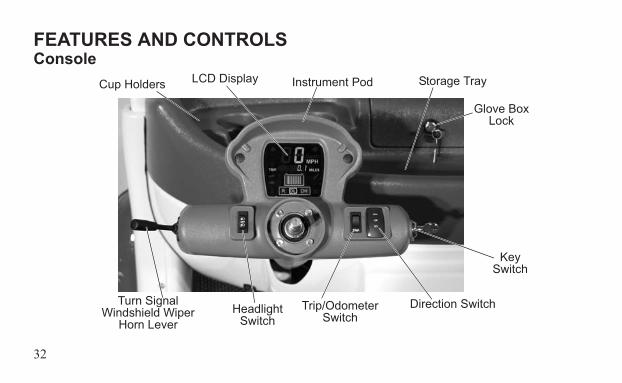
FEATURES AND CONTROLSConsole
Trip/Odometer Switch
Headlight Switch
Turn SignalWindshield Wiper
Horn Lever
Direction Switch
Key Switch
LCD Display
Glove Box Lock
Cup Holders Instrument Pod Storage Tray
33
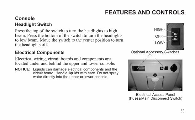
FEATURES AND CONTROLSConsoleHeadlight SwitchPress the top of the switch to turn the headlights to high beam. Press the bottom of the switch to turn the headlights to low beam. Move the switch to the center position to turn the headlights off.
Electrical ComponentsElectrical wiring, circuit boards and components are located under and behind the upper and lower console.NOTICE: Liquids can damage electrical components and the
circuit board. Handle liquids with care. Do not spray water directly into the upper or lower console.
Electrical Access Panel(Fuses/Main Disconnect Switch)
Optional Accessory Switches
HIGH
LOW
OFF
34
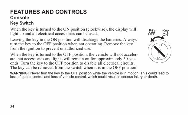
FEATURES AND CONTROLSConsoleKey SwitchWhen the key is turned to the ON position (clockwise), the display will light up and all electrical accessories can be used. Leaving the key in the ON position will discharge the batteries. Always turn the key to the OFF position when not operating. Remove the key from the ignition to prevent unauthorized use.When the key is turned to the OFF position, the vehicle will not acceler-ate, but accessories and lights will remain on for approximately 30 sec-onds. Turn the key to the OFF position to disable all electrical circuits. The key can be removed from the switch when it is in the OFF position.WARNING! Never turn the key to the OFF position while the vehicle is in motion. This could lead to loss of speed control and loss of vehicle control, which could result in serious injury or death.
Key ON
KeyOFF
35
FEATURES AND CONTROLSConsoleZero Speed Detection FeatureTo prevent the vehicle from rolling away, the electric motor will resist vehicle motion if the accelerator pedal is released while the key is on and the vehicle is moving.
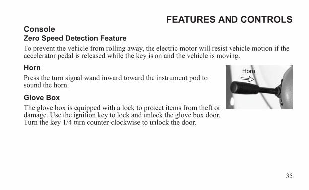
HornPress the turn signal wand inward toward the instrument pod to sound the horn.
Glove BoxThe glove box is equipped with a lock to protect items from theft or damage. Use the ignition key to lock and unlock the glove box door. Turn the key 1/4 turn counter-clockwise to unlock the door.
Horn
36
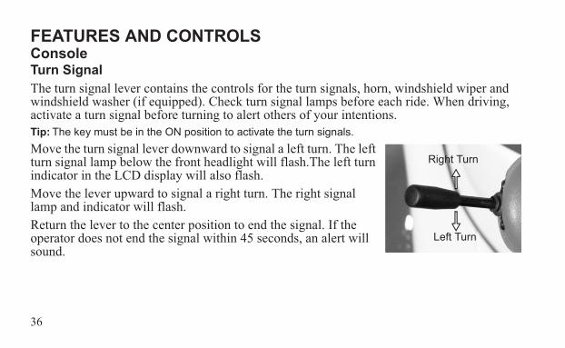
FEATURES AND CONTROLSConsoleTurn SignalThe turn signal lever contains the controls for the turn signals, horn, windshield wiper and windshield washer (if equipped). Check turn signal lamps before each ride. When driving, activate a turn signal before turning to alert others of your intentions.Tip: The key must be in the ON position to activate the turn signals.Move the turn signal lever downward to signal a left turn. The left turn signal lamp below the front headlight will flash.The left turn indicator in the LCD display will also flash.Move the lever upward to signal a right turn. The right signal lamp and indicator will flash.Return the lever to the center position to end the signal. If the operator does not end the signal within 45 seconds, an alert will sound.
Right Turn
Left Turn
37
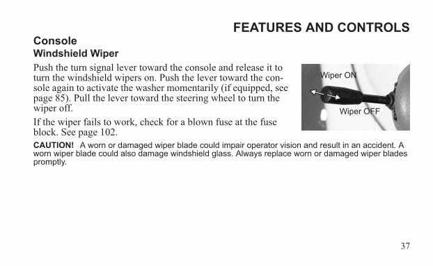
FEATURES AND CONTROLSConsoleWindshield WiperPush the turn signal lever toward the console and release it to turn the windshield wipers on. Push the lever toward the con-sole again to activate the washer momentarily (if equipped, see page 85). Pull the lever toward the steering wheel to turn the wiper off.If the wiper fails to work, check for a blown fuse at the fuse block. See page 102.CAUTION! A worn or damaged wiper blade could impair operator vision and result in an accident. A worn wiper blade could also damage windshield glass. Always replace worn or damaged wiper blades promptly.
Wiper OFF
Wiper ON
38
FEATURES AND CONTROLSConsoleTrip Meter/Odometer/E-MeterThe trip switch has four functions:• Toggle between the odometer and trip meter.• Reset the trip meter.• Change the function of the speedometer and odometer from miles per hour (MPH) to kilo-
meters per hour (km/h) and miles to kilometers.• Toggle between odometer/trip meter and e-meter to display accumulated power consumed
from grid, shown in kilowatt hours (kWh).
39
FEATURES AND CONTROLSConsoleTrip Meter/Odometer/E-Meter
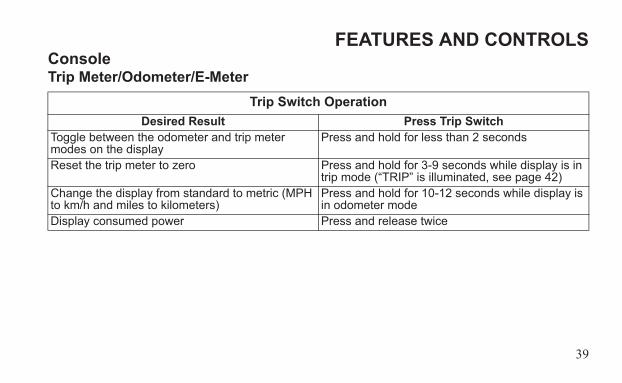
Trip Switch OperationDesired Result Press Trip Switch
Toggle between the odometer and trip meter modes on the display
Press and hold for less than 2 seconds
Reset the trip meter to zero Press and hold for 3-9 seconds while display is in trip mode (“TRIP” is illuminated, see page 42)
Change the display from standard to metric (MPH to km/h and miles to kilometers)
Press and hold for 10-12 seconds while display is in odometer mode
Display consumed power Press and release twice
40
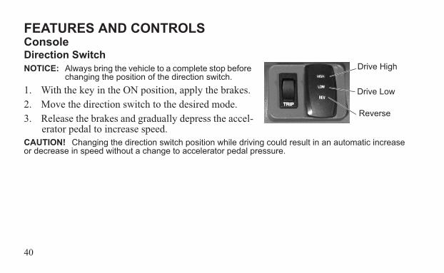
FEATURES AND CONTROLSConsoleDirection SwitchNOTICE: Always bring the vehicle to a complete stop before
changing the position of the direction switch. 1. With the key in the ON position, apply the brakes.2. Move the direction switch to the desired mode.3. Release the brakes and gradually depress the accel-
erator pedal to increase speed.CAUTION! Changing the direction switch position while driving could result in an automatic increase or decrease in speed without a change to accelerator pedal pressure.
Drive High
Drive Low
Reverse
41
FEATURES AND CONTROLSConsoleDirection SwitchDrive HighThe HIGH mode allows operation of the vehicle at speeds of 0-25 MPH (0-40 km/h).Drive LowThe LOW mode allows operation of the vehicle at speeds of 0-15 MPH (0-24 km/h). When LOW mode is selected, the rate of acceleration is also limited. ReverseA reverse warning alert will automatically sound when the key is on and reverse mode is selected. Vehicle speed is limited when operating in reverse. See page 90 for safe reverse operation procedures.
42
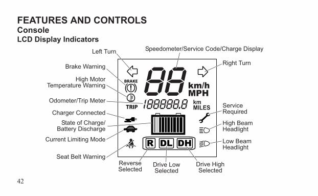
FEATURES AND CONTROLSConsoleLCD Display Indicators
kmMILESTRIP
BRAKE km/hMPH
Left Turn
Brake Warning
High MotorTemperature Warning
Odometer/Trip Meter
Charger ConnectedState of Charge/
Battery Discharge
Current Limiting Mode
Seat Belt WarningReverse Selected
Drive Low Selected
Drive High Selected
Low Beam Headlight
High Beam Headlight
Service Required
Right Turn
Speedometer/Service Code/Charge Display
43
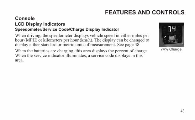
FEATURES AND CONTROLSConsoleLCD Display IndicatorsSpeedometer/Service Code/Charge Display IndicatorWhen driving, the speedometer displays vehicle speed in either miles per hour (MPH) or kilometers per hour (km/h). The display can be changed to display either standard or metric units of measurement. See page 38.When the batteries are charging, this area displays the percent of charge. When the service indicator illuminates, a service code displays in this area.
74% Charge
44
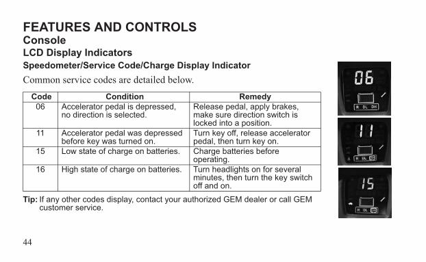
FEATURES AND CONTROLSConsoleLCD Display IndicatorsSpeedometer/Service Code/Charge Display IndicatorCommon service codes are detailed below.
Tip: If any other codes display, contact your authorized GEM dealer or call GEM customer service.
Code Condition Remedy06 Accelerator pedal is depressed,
no direction is selected. Release pedal, apply brakes, make sure direction switch is locked into a position.
11 Accelerator pedal was depressed before key was turned on.
Turn key off, release accelerator pedal, then turn key on.
15 Low state of charge on batteries. Charge batteries before operating.
16 High state of charge on batteries. Turn headlights on for several minutes, then turn the key switch off and on.
45
FEATURES AND CONTROLSConsoleLCD Display Indicators
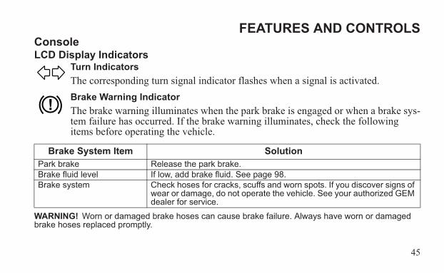
Turn IndicatorsThe corresponding turn signal indicator flashes when a signal is activated.Brake Warning IndicatorThe brake warning illuminates when the park brake is engaged or when a brake sys-tem failure has occurred. If the brake warning illuminates, check the following items before operating the vehicle.
WARNING! Worn or damaged brake hoses can cause brake failure. Always have worn or damaged brake hoses replaced promptly.
Brake System Item SolutionPark brake Release the park brake.Brake fluid level If low, add brake fluid. See page 98.Brake system Check hoses for cracks, scuffs and worn spots. If you discover signs of
wear or damage, do not operate the vehicle. See your authorized GEM dealer for service.
46
FEATURES AND CONTROLSConsoleLCD Display Indicators
High Motor Temperature Warning IndicatorIf the motor temperature warning illuminates, or if service code “41” displays in the speedometer/service code display, the motor or motor controller may be overheat-ing. Continued operation could result in motor damage. Stop the vehicle promptly,
preferably in a cool or shaded location, and wait for the motor to cool down. Do not operate the vehicle until the warning indicator turns off.Tip: Climbing steep grades while hauling heavy loads may overheat the motor or controller and shorten
component life.
47
FEATURES AND CONTROLSConsoleLCD Display IndicatorsOdometer/Trip Meter IndicatorThe odometer indicator logs the total distance the vehicle has been driven since it was manu-factured. The trip meter is useful for logging distances traveled on separate trips. See page 38 for trip meter instructions. The display can be changed to display either standard or metric units of measurement. See page 38.
Charger Connected IndicatorThis indicator illuminates approximately 8-10 seconds after the charger is connected and remains on until the charger is disconnected. If the indicator fails to
illuminate when the charger is connected, the charger may not be charging. If this occurs, make sure the main disconnect switch is in the ON position. See pages 61-65 for more information about charging the batteries.
48
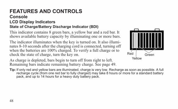
FEATURES AND CONTROLSConsoleLCD Display IndicatorsState of Charge/Battery Discharge Indicator (BDI)This indicator contains 8 green bars, a yellow bar and a red bar. It shows available battery capacity by illuminating one or more bars. The indicator illuminates when the key is turned on. It also illumi-nates 8-10 seconds after the charging cord is connected, turning off when the batteries are 100% charged. To verify a full charge or to check the state of charge, turn the key on.As charge is depleted, bars begin to turn off from right to left. Remaining bars indicate remaining battery charge. See page 49.Tip: If only red and yellow bars are illuminated, charge is very low. Recharge as soon as possible. A full
recharge cycle (from one red bar to fully charged) may take 8 hours or more for a standard battery pack, and up to 14 hours for a heavy duty battery pack.
RedYellow
Green
49
FEATURES AND CONTROLSConsoleLCD Display IndicatorsState of Charge/Battery Discharge Indicator (BDI)
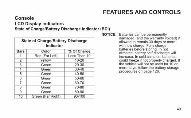
NOTICE: Batteries can be permanently damaged (and the warranty voided) if allowed to remain 30 days or more with low charge. Fully charge batteries before storing. In hot climates, battery self-discharge will increase. In cold climates, batteries could freeze if not properly charged. If the vehicle will not be used for 10 or more days, follow the battery storage procedures on page 126.
State of Charge/Battery Discharge Indicator
Bars Color % Of Charge1 Red (Far Left) Less Than 102 Yellow 10-203 Green 20-304 Green 30-405 Green 40-506 Green 50-607 Green 60-708 Green 70-809 Green 80-9010 Green (Far Right) 90-100
50
FEATURES AND CONTROLSConsoleLCD Display Indicators
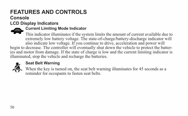
Current Limiting Mode IndicatorThis indicator illuminates if the system limits the amount of current available due to extremely low battery voltage. The state-of-charge/battery-discharge indicator will also indicate low voltage. If you continue to drive, acceleration and power will
begin to decrease. The controller will eventually shut down the vehicle to protect the batter-ies and motor from damage. If the state of charge is low and the current limiting indicator is illuminated, stop the vehicle and recharge the batteries.
Seat Belt WarningWhen the key is turned on, the seat belt warning illuminates for 45 seconds as a reminder for occupants to fasten seat belts.
51
FEATURES AND CONTROLSConsoleLCD Display Indicators
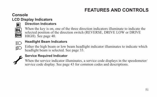
Direction IndicatorsWhen the key is on, one of the three direction indicators illuminate to indicate the selected position of the direction switch (REVERSE, DRIVE LOW or DRIVE HIGH). See page 40.Headlight Beam IndicatorsEither the high beam or low beam headlight indicator illuminates to indicate which headlight beam is selected. See page 33.Service Required IndicatorWhen the service indicator illuminates, a service code displays in the speedometer/service code display. See page 43 for common codes and descriptions.
52
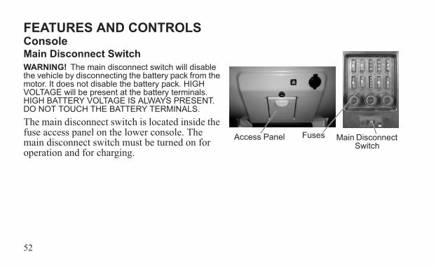
FEATURES AND CONTROLSConsoleMain Disconnect SwitchWARNING! The main disconnect switch will disable the vehicle by disconnecting the battery pack from the motor. It does not disable the battery pack. HIGH VOLTAGE will be present at the battery terminals. HIGH BATTERY VOLTAGE IS ALWAYS PRESENT. DO NOT TOUCH THE BATTERY TERMINALS.The main disconnect switch is located inside the fuse access panel on the lower console. The main disconnect switch must be turned on for operation and for charging.
Main Disconnect Switch
FusesAccess Panel
53
FEATURES AND CONTROLSConsoleMain Disconnect SwitchMove the switch to the left (OFF) to disconnect the battery pack from the motor. After the switch is turned off, some power may remain in the system until all capacitors have dis-charged.NOTICE: Do not turn off the disconnect switch while the vehicle is in motion or undergoing recharge
except in emergency situations.NOTICE: Damage to electrical connections and components will occur if they are unplugged before
the main disconnect switch is turned off. Always turn off the main disconnect switch before servicing or unplugging any electrical components.
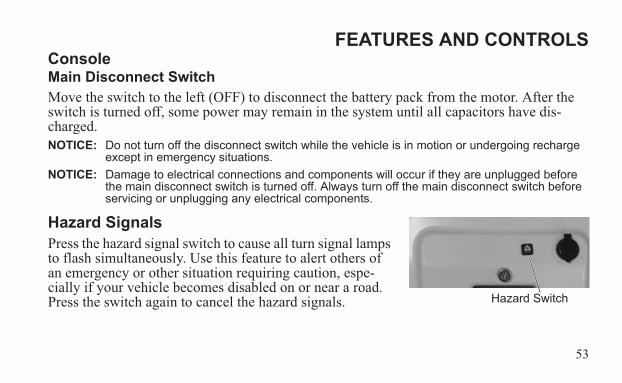
Hazard SignalsPress the hazard signal switch to cause all turn signal lamps to flash simultaneously. Use this feature to alert others of an emergency or other situation requiring caution, espe-cially if your vehicle becomes disabled on or near a road. Press the switch again to cancel the hazard signals. Hazard Switch
54
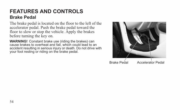
FEATURES AND CONTROLSBrake PedalThe brake pedal is located on the floor to the left of the accelerator pedal. Push the brake pedal toward the floor to slow or stop the vehicle. Apply the brakes before turning the key on.WARNING! Constant brake use (riding the brakes) can cause brakes to overheat and fail, which could lead to an accident resulting in serious injury or death. Do not drive with your foot resting or riding on the brake pedal.
Accelerator PedalBrake Pedal
55
FEATURES AND CONTROLSAccelerator PedalThe accelerator pedal is located on the floor to the right of the brake pedal. To begin moving or to increase vehicle speed, gradually push the accelerator pedal toward the floor. Holding the accelerator pedal down continuously will accelerate the vehicle to the maximum speed. The accelerator pedal will function only if the key is on. To slow the vehicle, release the accelerator pedal. Electric motor braking provides braking when the pedal is released. For additional speed control or to stop the vehicle, apply the brakes.
56
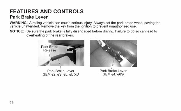
FEATURES AND CONTROLSPark Brake LeverWARNING! A rolling vehicle can cause serious injury. Always set the park brake when leaving the vehicle unattended. Remove the key from the ignition to prevent unauthorized use.NOTICE: Be sure the park brake is fully disengaged before driving. Failure to do so can lead to
overheating of the rear brakes.
Park Brake LeverGEM e4, e6®
Park Brake LeverGEM e2, eS, eL, eL XD
Park Brake Release
57
FEATURES AND CONTROLSPark Brake LeverThe park brake lever is located to the lower right of the driver seat. To help prevent the vehi-cle from rolling, set the park brake when parking the vehicle. When the park brake is set and the park brake indicator is illuminated, the vehicle will not move. Always apply the brakes before setting or releasing the park brake.The park brake is adjustable and should be checked periodically as outlined in the Periodic Maintenance Chart beginning on page 96. See your authorized GEM dealer for service. 1. To set the park brake, apply the brakes. Pull the park brake lever upward as far as possi-
ble.2. To release the park brake, apply the brakes. Press the park brake release inward and
move the lever downward as far as possible.
58
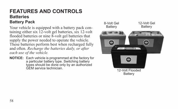
FEATURES AND CONTROLSBatteriesBattery PackYour vehicle is equipped with a battery pack con-taining either six 12-volt gel batteries, six 12-volt flooded batteries or nine 8-volt gel batteries that supply the power needed to operate the vehicle. These batteries perform best when recharged fully and often. Recharge the batteries daily, or after each use of the vehicle.NOTICE: Each vehicle is programmed at the factory for
a particular battery type. Switching battery types should be done only by an authorized GEM service technician.
8-Volt Gel Battery
12-Volt Flooded Battery
12-Volt Gel Battery
59
FEATURES AND CONTROLSBatteriesBattery Performance Tips• New batteries will not perform to their
fullest capacity until they have been dis-charged and recharged 20 to 30 times.
• Batteries should be fully charged before the first use.
• Recharge the batteries daily, or after each use of the vehicle.
• Always maintain a full charge on the bat-teries. For best battery life, avoid dis-charging the batteries more than 80%. See page 48.
• Batteries should be at room temperature when recharging. Do not charge batteries at temperatures of 110°F (43°C) or higher.
• In the first few years of life, the batteries should provide a range of up to 30 miles (48 km) at 72°F (22°C). At 32°F (0°C) range may be reduced to 12-15 miles (19-24 km). Actual range my be affected by road conditions, terrain, weather and driving habits.
60
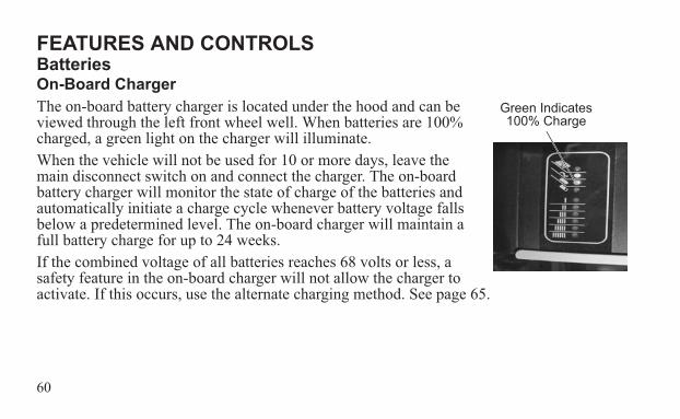
FEATURES AND CONTROLSBatteriesOn-Board ChargerThe on-board battery charger is located under the hood and can be viewed through the left front wheel well. When batteries are 100% charged, a green light on the charger will illuminate.When the vehicle will not be used for 10 or more days, leave the main disconnect switch on and connect the charger. The on-board battery charger will monitor the state of charge of the batteries and automatically initiate a charge cycle whenever battery voltage falls below a predetermined level. The on-board charger will maintain a full battery charge for up to 24 weeks.If the combined voltage of all batteries reaches 68 volts or less, a safety feature in the on-board charger will not allow the charger to activate. If this occurs, use the alternate charging method. See page 65.
Green Indicates 100% Charge
61
FEATURES AND CONTROLSBatteriesBattery ChargingWARNING! Using a non-recommended extension cord could result in fire, heat damage or charger failure, which could result in serious injury or death. Always use the recommended type of cord to charge the batteries. Tip: Do not use a ground fault interrupt (GFI) type cord on a GFCI-protected outlet.WARNING! Charging from a circuit of lesser capacity and/or using a cord from the outlet to the vehicle that is not sufficient in wire gauge could create a fire hazard.WARNING! Failure to provide adequate ventilation while charging batteries can result in an explosion. Hydrogen gas is emitted during charging and will rise and accumulate at the ceiling. Always ensure a minimum of five (5) air changes per hour in the charging area. Never charge the batteries in an area subject to a flame or spark, including areas containing gas or propane water heaters and furnaces. Do not smoke in the charging area.
62
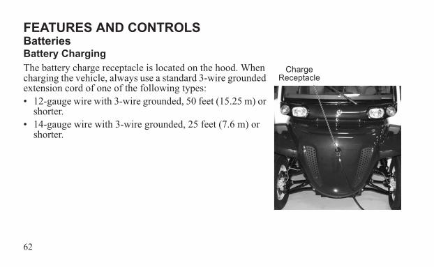
FEATURES AND CONTROLSBatteriesBattery ChargingThe battery charge receptacle is located on the hood. When charging the vehicle, always use a standard 3-wire grounded extension cord of one of the following types:• 12-gauge wire with 3-wire grounded, 50 feet (15.25 m) or
shorter.• 14-gauge wire with 3-wire grounded, 25 feet (7.6 m) or
shorter.
Charge Receptacle
63
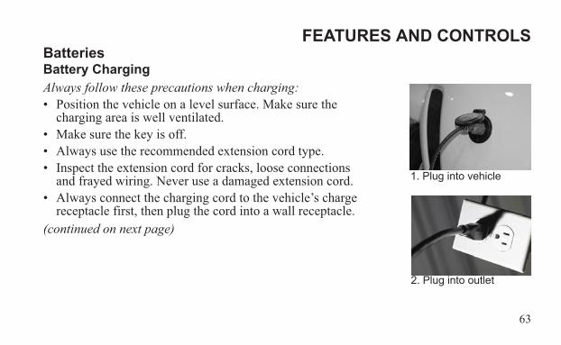
FEATURES AND CONTROLSBatteriesBattery ChargingAlways follow these precautions when charging:• Position the vehicle on a level surface. Make sure the
charging area is well ventilated.• Make sure the key is off.• Always use the recommended extension cord type.• Inspect the extension cord for cracks, loose connections
and frayed wiring. Never use a damaged extension cord.• Always connect the charging cord to the vehicle’s charge
receptacle first, then plug the cord into a wall receptacle.(continued on next page)
1. Plug into vehicle
2. Plug into outlet
64
FEATURES AND CONTROLSBatteriesBattery ChargingTip: Always use a 110-volt AC, 15 amp breaker outlet. A GFI (Ground Fault Interrupt) receptacle is rec-
ommended. See your authorized GEM dealer if you do not have a GFI receptacle at your regular recharge site.
• Make sure the charger uses a dedicated circuit to prevent overloading. If charging multiple vehicles, each vehicle should use a dedicated circuit.
• When disconnecting the charger, always disconnect the extension cord from the wall receptacle first, then disconnect the cord from the vehicle.
65
FEATURES AND CONTROLSBatteriesAlternate Battery Charging MethodIf the combined voltage of all batteries reaches 68 volts or less, a safety feature in the on-board charger will not allow the charger to activate. Use the alternate charging method to add a small charge to each battery separately. The on-board charger will then activate properly to recharge all batteries to a full charge.Use a 12-volt battery charger to charge 12-volt batteries. Charge each battery individually.Use a 24-volt charger to charge 8-volt batteries. Charge in 3 groups, each consisting of 3 sequentially wired batteries.Tip: It is not necessary to remove or disconnect battery post connections during the alternate charging
method.
66
FEATURES AND CONTROLSBatteriesAlternate Battery Charging Method1. Turn the main disconnect switch off. 2. Set the battery charger to the medium amp setting (10 to 30 amps). 3. Charge each battery for 10-20 minutes. 4. Move quickly from battery to battery, as this is only a residual charge and it will dissi-
pate in a short period of time. 5. After charging the last battery, remove the off-board charger leads, turn the main discon-
nect switch on and plug the vehicle in.6. If the on-board charger does not recognize the residual charge and activate, repeat the
alternate charging method.
67
FEATURES AND CONTROLSBatteriesBattery Handling PrecautionsWARNING! Do not work in or near the battery compartment or on any other electrical component of the vehicle while charging the batteries. Always turn off the main disconnect switch before servicing or unplugging any electrical components. See page 52. The main disconnect switch will disable the vehicle by disconnecting the battery pack from the motor. It does not disable the battery pack. HIGH VOLTAGE will be present at the battery terminals. HIGH BATTERY VOLTAGE IS ALWAYS PRESENT. DO NOT TOUCH THE BATTERY TERMINALS.• Always make sure that all electrical accessories are grounded directly to the negative (-)
post on the terminal board. Never use the chassis or body as a ground connection.• Make sure vent caps are installed properly and securely during vehicle operation and bat-
tery charging.• Never connect a 12-volt accessory directly to the batteries. Always connect any powered
accessory to a 12-volt auxiliary outlet or terminal board.(continued on next page)
68
FEATURES AND CONTROLSBatteriesBattery Handling Precautions• Never connect jumper cables to any of the batteries of this vehicle.• Always wear safety glasses or approved eye protection when servicing the vehicle. Wear a
full-face shield and gloves when working with or around batteries and electrical connec-tors.
• Use only insulated tools when working in the battery compartment.• Always keep battery terminals and connections clean and free of corrosion at all times.
See page 122.
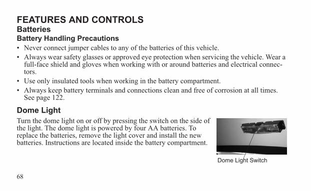
Dome LightTurn the dome light on or off by pressing the switch on the side of the light. The dome light is powered by four AA batteries. To replace the batteries, remove the light cover and install the new batteries. Instructions are located inside the battery compartment.
Dome Light Switch
69
FEATURES AND CONTROLS
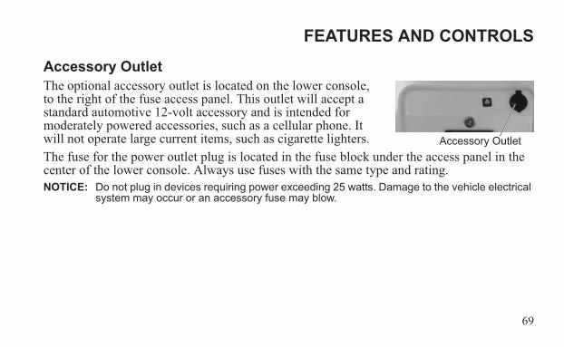
Accessory OutletThe optional accessory outlet is located on the lower console, to the right of the fuse access panel. This outlet will accept a standard automotive 12-volt accessory and is intended for moderately powered accessories, such as a cellular phone. It will not operate large current items, such as cigarette lighters.The fuse for the power outlet plug is located in the fuse block under the access panel in the center of the lower console. Always use fuses with the same type and rating.NOTICE: Do not plug in devices requiring power exceeding 25 watts. Damage to the vehicle electrical
system may occur or an accessory fuse may blow.
Accessory Outlet
70
FEATURES AND CONTROLSBench Seat RemovalPull up on the front of the seat to disengage the front latches. Slide the seat forward and lift it away from the seat base. To reinstall the seat, align the rear plunger to the socket at the rear of the seat base. Slide the seat fully rearward, then push down firmly along the front edge of the seat to secure the latches.
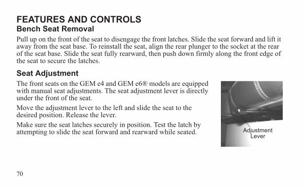
Seat AdjustmentThe front seats on the GEM e4 and GEM e6® models are equipped with manual seat adjustments. The seat adjustment lever is directly under the front of the seat.Move the adjustment lever to the left and slide the seat to the desired position. Release the lever.Make sure the seat latches securely in position. Test the latch by attempting to slide the seat forward and rearward while seated. Adjustment
Lever
71
FEATURES AND CONTROLSSeat Belts
Failure to properly use seat belts and child restraints can result in serious injury or death. Always follow all legal requirements for seat belt and child restraint use in on-road vehicles. • Always make sure the seat belts are secured for operator and all passengers before operating.• Pregnant women should wear the lap part of the belt across the thighs and as snug across the hips
as possible. Keep the belt low so that it does not come across the abdomen.• The operator and all passengers are subject to the same legal requirements for seat belt use as
occupants in other on-road vehicles. Always make sure children are properly restrained. Children ages 12 and under should ride in a rear seat. Infants must always be restrained in a rear seat. Use the type of restraint that is correct for your child. When using child safety seats, always follow the manufacturer’s instructions for proper installation and use in a vehicle containing only a shoulder/lap belt restraint system. Visit www.seatcheck.org or call 1-866-SEATCHECK for more information about child restraints.
WARNING
72
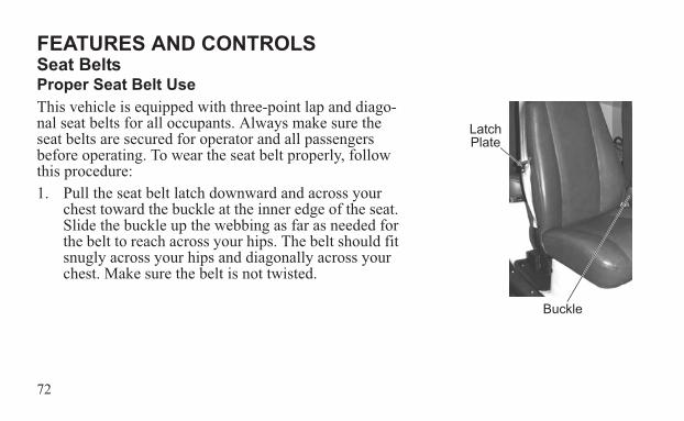
FEATURES AND CONTROLSSeat BeltsProper Seat Belt UseThis vehicle is equipped with three-point lap and diago-nal seat belts for all occupants. Always make sure the seat belts are secured for operator and all passengers before operating. To wear the seat belt properly, follow this procedure:1. Pull the seat belt latch downward and across your
chest toward the buckle at the inner edge of the seat. Slide the buckle up the webbing as far as needed for the belt to reach across your hips. The belt should fit snugly across your hips and diagonally across your chest. Make sure the belt is not twisted.
Buckle
Latch Plate
73
FEATURES AND CONTROLSSeat BeltsProper Seat Belt Use2. Push the latch plate into the buckle until it clicks.3. Release the strap, it will self tighten. 4. To remove slack in the lap belt portion of the belt, pull upward on the shoulder belt. To
loosen the lap belt if it is too tight, tilt the buckle and pull the lap belt slightly longer.5. To release the seat belt, press the square red button in the buckle's center. If necessary,
slide the buckle down the webbing to allow it to retract fully.
74
FEATURES AND CONTROLSSeat BeltsSeat Belt Safety Tips• In a rear seat, you may have trouble tightening the lap/shoulder belt on the child restraint
because the buckle or latch plate is too close to the belt path opening on the restraint. Dis-connect the latch plate from the buckle and twist the short buckle-end belt several times to shorten it. Insert the latch plate into the buckle with the release button facing outward.
• If the belt still cannot be tightened when using a child safety seat, or if pulling and pushing on the restraint loosens the belt, disconnect the latch plate from the buckle, turn the buckle around and insert the latch plate into the buckle again. If you still cannot make the child restraint secure, try a different seating position.
75
FEATURES AND CONTROLSSeat BeltsSeat Belt InspectionInspect all seat belts for proper operation before each use of the vehicle.1. Push the latch plate into the buckle until it clicks. The latch plate must slide smoothly
into the buckle. A click indicates that it's securely latched.2. Push the red release latch in the middle of the buckle to make sure it releases freely. 3. Pull each seat belt completely out and inspect the full length for any damage, including
cuts, wear, fraying or stiffness. If any damage is found, or if the seat belt does not oper-ate properly, have the seat belt system checked and/or replaced by your authorized GEM dealer.
4. To clean dirt or debris from the seat belts, sponge the straps with mild soap and water. Do not use bleach, dye or household detergents.
76
FEATURES AND CONTROLSStereo System (Option)The optional stereo system is mounted in an overhead console and fea-tures speakers, FM radio, CD player and MP3 capabilities. Refer to your stereo system’s user manual for detailed operating instructions.
77
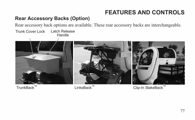
FEATURES AND CONTROLSRear Accessory Backs (Option)Rear accessory back options are available. These rear accessory backs are interchangeable.
Latch Release Handle
Trunk Cover Lock
TrunkBack™ LinksBack™ Clip-In StakeBack™
78
FEATURES AND CONTROLSRear Accessory Backs (Option)WARNING! Never carry a passenger on a rear accessory back. Do not overload an accessory back. Overloading the vehicle can reduce stability and handling and could cause loss of control. Never exceed the GVWR or the GAWR. See page 22.NOTICE: Use only GEM-approved rear accessories. Others may cause damage to the locking system
or vehicle, and will void warranty.1. Remove the contents of the installed rear accessory back.2. Ensure that the safety strap is secured.CAUTION! Before releasing the rear latch, always make sure the safety strap is secure. The rear back can fall suddenly and cause injury or damage to the vehicle if the safety strap is not secured.3. Firmly grasp the installed back to prevent it from tipping or falling.4. Use the ignition key to unlock the latch release handle.Tip: There is a separate key for the TrunkBack™ cover lock.
79
FEATURES AND CONTROLSRear Accessory Backs (Option)5. Rotate the release handle to release the dual latches.6. Remove the safety strap and carefully remove the existing accessory back.7. Install the desired accessory back onto the mounting brackets.8. Secure the safety strap.9. Push the accessory back forward to engage the dual latches. Make sure you hear two
clicks, one for each latch engagement. Test to make sure the latches are secure. If not secure, repeat this step.
CAUTION! Keep the rear latch in a locked position when operating or transporting the vehicle. The rear accessory could fall and cause injury if the safety strap is not used.10. Always lock the release handle with the ignition key after changing accessory backs.
80
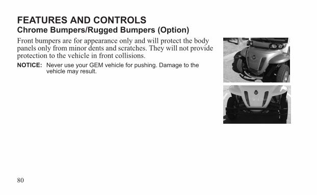
FEATURES AND CONTROLSChrome Bumpers/Rugged Bumpers (Option)Front bumpers are for appearance only and will protect the body panels only from minor dents and scratches. They will not provide protection to the vehicle in front collisions.NOTICE: Never use your GEM vehicle for pushing. Damage to the
vehicle may result.
81
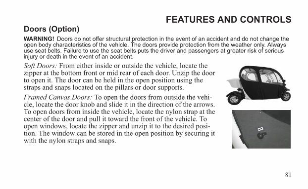
FEATURES AND CONTROLSDoors (Option)WARNING! Doors do not offer structural protection in the event of an accident and do not change the open body characteristics of the vehicle. The doors provide protection from the weather only. Always use seat belts. Failure to use the seat belts puts the driver and passengers at greater risk of serious injury or death in the event of an accident.Soft Doors: From either inside or outside the vehicle, locate the zipper at the bottom front or mid rear of each door. Unzip the door to open it. The door can be held in the open position using the straps and snaps located on the pillars or door supports. Framed Canvas Doors: To open the doors from outside the vehi-cle, locate the door knob and slide it in the direction of the arrows. To open doors from inside the vehicle, locate the nylon strap at the center of the door and pull it toward the front of the vehicle. To open windows, locate the zipper and unzip it to the desired posi-tion. The window can be stored in the open position by securing it with the nylon straps and snaps.
82
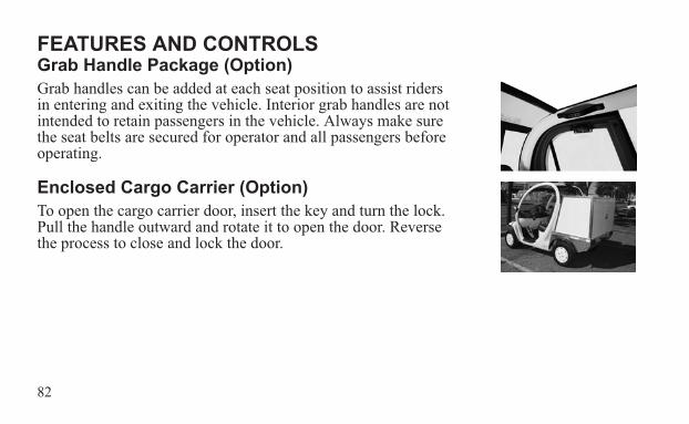
FEATURES AND CONTROLSGrab Handle Package (Option)Grab handles can be added at each seat position to assist riders in entering and exiting the vehicle. Interior grab handles are not intended to retain passengers in the vehicle. Always make sure the seat belts are secured for operator and all passengers before operating.
Enclosed Cargo Carrier (Option)To open the cargo carrier door, insert the key and turn the lock. Pull the handle outward and rotate it to open the door. Reverse the process to close and lock the door.
83
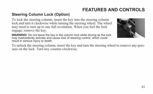
FEATURES AND CONTROLSSteering Column Lock (Option)To lock the steering column, insert the key into the steering column lock and turn it clockwise while turning the steering wheel. The wheel may need to turn up to one full revolution. When you feel the lock engage, remove the key.WARNING! Do not leave the key in the column lock while driving as the lock may inadvertently activate and cause loss of steering control, which could result in serious injury or death.To unlock the steering column, insert the key and turn the steering wheel to remove any pres-sure on the lock. Turn key counter-clockwise.
84
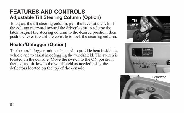
FEATURES AND CONTROLSAdjustable Tilt Steering Column (Option)To adjust the tilt steering column, pull the lever at the left of the column rearward toward the driver’s seat to release the latch. Adjust the steering column to the desired position, then push the lever toward the console to lock the steering column.
Heater/Defogger (Option)The heater/defogger unit can be used to provide heat inside the vehicle and to assist in defogging the windshield. The switch is located on the console. Move the switch to the ON position, then adjust airflow to the windshield as needed using the deflectors located on the top of the console.
Tilt Lever
Heater/Defogger Switch
Deflector
85
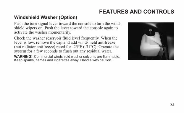
FEATURES AND CONTROLSWindshield Washer (Option)Push the turn signal lever toward the console to turn the wind-shield wipers on. Push the lever toward the console again to activate the washer momentarily.Check the washer reservoir fluid level frequently. When the level is low, remove the cap and add windshield antifreeze (not radiator antifreeze) rated for -25°F (-31°C). Operate the system for a few seconds to flush out any residual water.WARNING! Commercial windshield washer solvents are flammable. Keep sparks, flames and cigarettes away. Handle with caution.
86
OPERATION
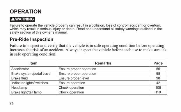
Failure to operate the vehicle properly can result in a collision, loss of control, accident or overturn, which may result in serious injury or death. Read and understand all safety warnings outlined in the safety section of this owner’s manual.
Pre-Ride InspectionFailure to inspect and verify that the vehicle is in safe operating condition before operating increases the risk of an accident. Always inspect the vehicle before each use to make sure it's in safe operating condition.
Item Remarks PageAccelerator Ensure proper operation 55Brake system/pedal travel Ensure proper operation 98Brake fluid Ensure proper level 98Indicator lights/switches Ensure operation 42Headlamp Check operation 109Brake light/tail lamp Check operation 110
WARNING
87
OPERATIONPre-Ride Inspection
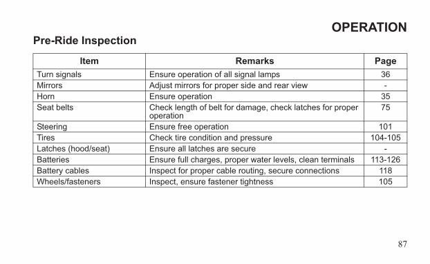
Item Remarks PageTurn signals Ensure operation of all signal lamps 36Mirrors Adjust mirrors for proper side and rear view -Horn Ensure operation 35Seat belts Check length of belt for damage, check latches for proper
operation75
Steering Ensure free operation 101Tires Check tire condition and pressure 104-105Latches (hood/seat) Ensure all latches are secure -Batteries Ensure full charges, proper water levels, clean terminals 113-126Battery cables Inspect for proper cable routing, secure connections 118Wheels/fasteners Inspect, ensure fastener tightness 105
88
OPERATIONDriving Procedure1. Disconnect the charging cable. Make sure the main disconnect switch is on.2. Sit in the driver's seat and fasten the seat belt. Make sure passengers are seated with seat
belts secured.3. Adjust mirrors as needed. 4. Turn the key clockwise to the ON position.5. Apply the brakes.6. Release the park brake.7. Move the direction switch to the desired position. See page 40.8. Check your surroundings and determine your path of travel.9. Keeping both hands on the steering wheel, release the brake pedal and gradually push
the accelerator toward the floor to begin driving.10. Drive slowly. Practice maneuvering and using the accelerator and brakes on level sur-
faces.
89
OPERATIONDriving Procedure11. Before turning, activate a turn signal to alert others of your intentions. See page 36.12. Do not carry a passenger until you have at least two hours of driving experience with this
vehicle. Allow a passenger to ride only in a designated passenger seat with seat belt secured.
13. To stop the vehicle, release the accelerator pedal completely and brake to a complete stop.
NOTICE: Always bring the vehicle to a complete stop before changing the position of the direction switch.
14. Set the park brake.WARNING! A rolling vehicle can cause serious injury or death. Always set the park brake when leaving the vehicle unattended.15. Turn the key off.16. Recharge the batteries daily, or after each use of the vehicle.
90
OPERATIONDriving in ReverseFollow these precautions when operating in reverse:1. Always check for obstacles or people behind the vehicle. Always inspect left and right
fields of vision before backing.2. Avoid backing downhill.3. Back slowly.4. Apply the brakes lightly for stopping.5. Avoid turning at sharp angles.6. Never accelerate suddenly.
91
OPERATIONDriving On Slippery Surfaces
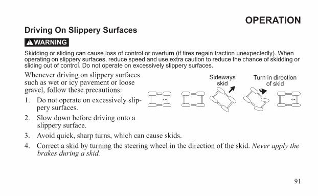
Skidding or sliding can cause loss of control or overturn (if tires regain traction unexpectedly). When operating on slippery surfaces, reduce speed and use extra caution to reduce the chance of skidding or sliding out of control. Do not operate on excessively slippery surfaces.Whenever driving on slippery surfaces such as wet or icy pavement or loose gravel, follow these precautions:1. Do not operate on excessively slip-
pery surfaces.2. Slow down before driving onto a
slippery surface.3. Avoid quick, sharp turns, which can cause skids.4. Correct a skid by turning the steering wheel in the direction of the skid. Never apply the
brakes during a skid.
WARNING
Sideways skid
Turn in direction of skid
92
OPERATIONParking the Vehicle1. Apply the brakes. Stop the vehicle on a level surface.2. When parking inside a garage or other structure, be sure that the structure is well venti-
lated and that the vehicle is not close to any source of flame or sparks, including any appliance with pilot lights.
3. Place the direction switch on either forward position.4. Set the park brake.5. Turn the key off. Remove the key from the ignition to prevent unauthorized use.
93
OPERATIONParking on an InclineAvoid parking on an incline if possible. If it's unavoidable, follow these precautions:• If parking in an open area, block the wheels on the downhill side of the vehicle after turn-
ing the key off.• If parking parallel to a curb, stop the vehicle close to the curb. If the vehicle is facing
downhill, turn the steering wheel toward the curb. The forward part of the front tire should be turned into the curb. If the vehicle is facing uphill, turn the steering wheel away from the curb. The rear part of the front tire should be turned into the curb.
• Set the park brake.
94
OPERATIONTransporting the VehicleNOTICE: Towing your GEM vehicle could result in severe damage to the vehicle. Vehicle failures
resulting from dolly towing will void warranty.When transporting the GEM vehicle on a trailer, always use a trailer with an approved load rating greater than the GEM vehicle’s curb weight plus any installed accessories or cargo. Refer to the specifications section beginning on page 134.Always tie the frame of the GEM vehicle to the transporting unit securely with suitable straps. Always secure the straps to the front sub-frame and the rear axle of the GEM vehicle. Never place tie straps across any plastic body or floor panel components.(continued on next page)
95
OPERATIONTransporting the VehicleTransport the vehicle in a closed trailer if possible. Use the following guidelines when trans-porting the vehicle on an open trailer. 1. Always transport the GEM vehicle facing forward on the trailer.2. Set the park brake.3. Remove the key to prevent loss.4. Secure the seats, hood and any items that could be damaged or dislodged by strong
winds. If equipped with hard doors, put all windows down.5. Never allow passengers on a trailer or in a trailered vehicle.6. Reduce speed and drive with caution.
96
MAINTENANCEPeriodic Maintenance ChartWARNING! Always wear safety glasses or approved eye protection when servicing the vehicle. Wear a full-face shield and gloves when working with or around batteries and electrical connectors. Always use insulated tools when working with or near batteries. Failure to follow these instructions could result in serious injury or death. NOTICE: Damage to electrical connections and components will occur if they are unplugged before
the main disconnect switch is turned off. Always turn off the main disconnect switch before servicing or unplugging any electrical components.
Careful periodic maintenance will help keep your vehicle in the safest, most reliable condi-tion. Inspect, clean, lubricate, adjust and replace parts as necessary. When inspection reveals the need for replacement parts, always use genuine GEM parts available from your autho-rized GEM dealer. Record maintenance and service in the Maintenance Log beginning on page 147.Tip: Service and adjustments are important for proper vehicle operation. If you're not familiar with safe
service and adjustment procedures, have your authorized GEM dealer perform these operations.
97
MAINTENANCEPeriodic Maintenance Chart
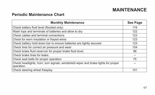
Monthly Maintenance See PageCheck battery fluid level (flooded only) 119Wash tops and terminals of batteries and allow to dry 122Check cables and terminal connections 123Check for worn insulation or frayed wires 123Check battery hold-down bar to ensure batteries are tightly secured 123Check tires for correct air pressure and wear 104Check brake fluid reservoir for proper brake fluid level. 98Check brake lines for leaks. --Check seat belts for proper operation 75Check headlights, horn, turn signals, windshield wiper and brake lights for proper operation.
--
Check steering wheel freeplay 101
98
MAINTENANCEBrakesBrake FluidInspect the brake system routinely. Inspect the brake fluid level before each operation. If the level drops between fluid checks, add brake fluid as needed. See your authorized GEM dealer for service.WARNING! After opening a bottle of brake fluid, always discard any unused portion. Never store or use a partial bottle. Brake fluid is hygroscopic, meaning it rapidly absorbs moisture from the air. The moisture causes the boiling temperature of the brake fluid to drop, which can lead to early brake fade and the possibility of accident or severe injury.Change the brake fluid every two years and any time the fluid becomes contaminated, the fluid level is below the minimum, or if the type and brand of the fluid in the reservoir are unknown. Always use DOT4 brake fluid.
99
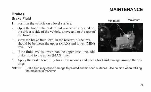
MAINTENANCEBrakesBrake Fluid1. Position the vehicle on a level surface. 2. Open the hood. The brake fluid reservoir is located on
the driver’s side of the vehicle, above and to the rear of the front tire.
3. View the brake fluid level in the reservoir. The level should be between the upper (MAX) and lower (MIN) level lines.
4. If the fluid level is lower than the upper level line, add brake fluid to the upper (MAX) line.
5. Apply the brake forcefully for a few seconds and check for fluid leakage around the fit-tings.
NOTICE: Brake fluid may cause damage to painted and finished surfaces. Use caution when refilling the brake fluid reservoir.
MaximumMinimum
100
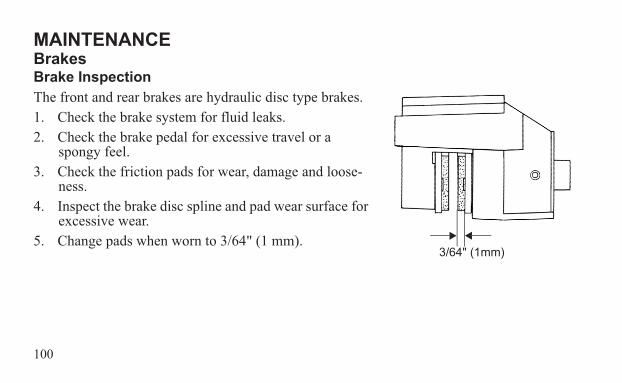
MAINTENANCEBrakesBrake InspectionThe front and rear brakes are hydraulic disc type brakes.1. Check the brake system for fluid leaks.2. Check the brake pedal for excessive travel or a
spongy feel. 3. Check the friction pads for wear, damage and loose-
ness.4. Inspect the brake disc spline and pad wear surface for
excessive wear.5. Change pads when worn to 3/64" (1 mm).
3/64" (1mm)
101
MAINTENANCESteering Wheel InspectionCheck the steering wheel for specified freeplay and smooth operation.1. Position the vehicle on a level surface.2. Lightly turn the steering wheel left and right. There should be 0.8-1.0 inch (20-25 mm)
of freeplay at the outer rim of the steering wheel.3. If there is excessive freeplay or strange noises, or the steering feels rough or “catchy,”
have the steering system inspected by your authorized GEM dealer.
102
MAINTENANCEFuse ReplacementNOTICE: Always turn off the main disconnect switch
before servicing or unplugging any electrical components. See page 52.
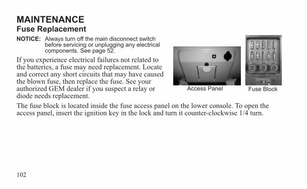
If you experience electrical failures not related to the batteries, a fuse may need replacement. Locate and correct any short circuits that may have caused the blown fuse, then replace the fuse. See your authorized GEM dealer if you suspect a relay or diode needs replacement.The fuse block is located inside the fuse access panel on the lower console. To open the access panel, insert the ignition key in the lock and turn it counter-clockwise 1/4 turn.
Fuse BlockAccess Panel
103
MAINTENANCEFuse Replacement
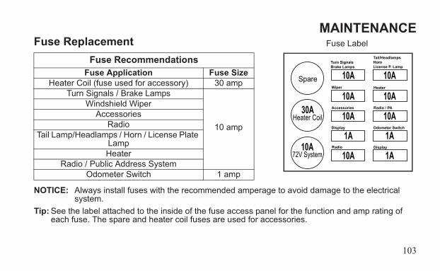
NOTICE: Always install fuses with the recommended amperage to avoid damage to the electrical system.
Tip: See the label attached to the inside of the fuse access panel for the function and amp rating of each fuse. The spare and heater coil fuses are used for accessories.
Fuse RecommendationsFuse Application Fuse Size
Heater Coil (fuse used for accessory) 30 ampTurn Signals / Brake Lamps
10 amp
Windshield WiperAccessories
RadioTail Lamp/Headlamps / Horn / License Plate
LampHeater
Radio / Public Address SystemOdometer Switch 1 amp
Spare
Heater Coil
72V System
30A
10A
10A
10A
10A
10A
1A
10A
10A
10A
1A
1A
Turn SignalsBrake Lamps
Wiper
Accessories
Display
Radio
Tail/HeadlampsHornLicense P. Lamp
Heater
Radio / PA
Odometer Switch
Display
Fuse Label
104
MAINTENANCETires
Operating your vehicle with worn tires, improperly inflated tires, non-standard tires or improperly installed tires will affect vehicle handling and could cause an accident resulting in serious injury or death. Always follow all tire maintenance procedures as outlined in this manual and on the labels on the vehicle. Always use original equipment size and type when replacing tires.
Tire PressureWARNING! Improper tire pressure can cause loss of control resulting in severe injury or death.Proper tire pressure is essential to the safe and comfortable operation of your vehicle. Check tire pressure daily, or before each use of the vehicle. For recommended tire pressures, see the manufacturer’s label on your vehicle or the specifications section beginning on page 134.NOTICE: After inspecting or adjusting the tire pressure, always reinstall the valve stem cap (if
equipped). This will prevent moisture and dirt from entering the valve stem, which could cause damage.
WARNING
105
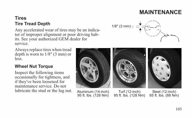
MAINTENANCETiresTire Tread DepthAny accelerated wear of tires may be an indica-tor of improper alignment or poor driving hab-its. See your authorized GEM dealer for service.Always replace tires when tread depth is worn to 1/8" (3 mm) or less.
Wheel Nut TorqueInspect the following items occasionally for tightness, and if they've been loosened for maintenance service. Do not lubricate the stud or the lug nut.
1/8" (3 mm)
Aluminum (14-inch)95 ft. lbs. (128 Nm)
Steel (12-inch)65 ft. lbs. (88 Nm)
Turf (12-inch)95 ft. lbs. (128 Nm)
106
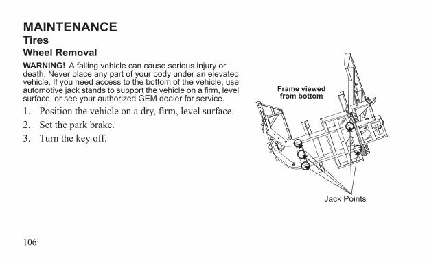
MAINTENANCETiresWheel RemovalWARNING! A falling vehicle can cause serious injury or death. Never place any part of your body under an elevated vehicle. If you need access to the bottom of the vehicle, use automotive jack stands to support the vehicle on a firm, level surface, or see your authorized GEM dealer for service.1. Position the vehicle on a dry, firm, level surface.2. Set the park brake.3. Turn the key off.
Jack Points
Frame viewed from bottom
107
MAINTENANCETiresWheel Removal4. Block both the front and rear of the tire that is located diagonally opposite the jacking
position. For example, if the right front tire is being changed, block the left rear wheel.5. Use a small floor style jack or low profile scissors jack only. Jack the vehicle only from
the side of the vehicle, on the main frame rail, at the point where the tub or floor panel support and the main frame rail are welded. Alternative locations include the rear frame rail and the center of the front crossmember.
NOTICE: Jacking at any location other than the recommended jacking points may cause significant damage to the vehicle frame and body.
6. Remove the wheel nuts.7. Remove the wheel.
108
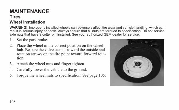
MAINTENANCETiresWheel InstallationWARNING! Improperly installed wheels can adversely affect tire wear and vehicle handling, which can result in serious injury or death. Always ensure that all nuts are torqued to specification. Do not service axle nuts that have a cotter pin installed. See your authorized GEM dealer for service.1. Set the park brake.2. Place the wheel in the correct position on the wheel
hub. Be sure the valve stem is toward the outside and rotation arrows on the tire point toward forward rota-tion.
3. Attach the wheel nuts and finger tighten.4. Carefully lower the vehicle to the ground.5. Torque the wheel nuts to specification. See page 105.
109
MAINTENANCELightsPoor lighting can result in reduced visibility when driving. Clean lights frequently and replace burned out lamps promptly. Always make sure lights are adjusted properly for best visibility. When servicing a halogen lamp, don't touch the lamp with bare fingers. Oil from your skin leaves a residue, causing a hot spot that will shorten the life of the lamp.
Headlight ReplacementIf a headlight fails to work properly, an expired lamp may need replacement. Apply dielectric grease to the socket before installing the new lamp.
Front Turn Signal Light ReplacementIf a front turn signal fails to work properly, the entire assembly must be replaced. See your authorized GEM dealer for service. If your vehicle is equipped with optional high/low beam headlights, an expired front turn signal lamp can be replaced. Apply dielectric grease to the socket before installing the new lamp.
110
MAINTENANCELightsRear Turn Signal Light Replacement1. Remove the rear turn signal lens.2. Remove the expired lamp.3. Apply dielectric grease to the socket before installing the new lamp.4. Test the light for proper operation.
Brake Lights1. Remove the brake light lens.2. Remove the expired lamp.3. Apply dielectric grease to the socket before installing the new lamp.4. Test the light for proper operation.
111
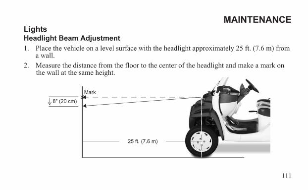
MAINTENANCELightsHeadlight Beam Adjustment1. Place the vehicle on a level surface with the headlight approximately 25 ft. (7.6 m) from
a wall.2. Measure the distance from the floor to the center of the headlight and make a mark on
the wall at the same height.
25 ft. (7.6 m)
8" (20 cm)X
Mark
112
MAINTENANCELightsHeadlight Beam Adjustment3. Apply the brakes. Turn the key on. Turn the headlights to high beam.Tip: Include the weight of a rider on the seat while performing the following step.4. Observe the headlight aim. The most intense part of the headlight beam should be aimed
8" (20 cm) below the mark placed on the wall.5. If a headlight needs adjustment, access the adjustment screw under the hood or through
the wheel well.6. Loosen the screw, adjust the headlight, and tighten the screw.7. Repeat steps 4-6 until the lamp is properly adjusted.
113
MAINTENANCEBatteries
The voltage in the battery pack is sufficient to cause death by electrocution. With the exception of battery inspections and refilling the water in flooded type batteries, never attempt to perform service on the electric drive system, including the battery pack, unless you are properly trained to work on electrical systems. Always see your authorized GEM dealer for battery-related service.
Battery posts, terminals and related components contain lead and lead compounds, chemicals known to cause cancer and reproductive harm. Always wash your hands after touching or handling the batteries.
Charging a damaged battery can result in serious injury. Never attempt to charge a frozen or bulging battery. Discard the battery appropriately and install a new battery.
WARNING
WARNING
WARNING
114
MAINTENANCEBatteries
Improperly connecting or disconnecting battery cables can result in an explosion and cause serious injury or death.
Battery electrolyte is poisonous. It contains sulfuric acid. Serious burns can result from contact with skin, eyes or clothing.Antidote:External: Flush with water.Internal: Drink large quantities of water or milk. Follow with milk of magnesia, beaten egg, or vegetable oil. Call physician immediately.Eyes: Flush with water for 15 minutes and get prompt medical attention.Batteries produce explosive gases. Keep sparks, flame, cigarettes, etc. away. Ventilate when charging or using in an enclosed space. Always shield eyes when working near batteries. KEEP OUT OF REACH OF CHILDREN.
WARNING
WARNING
115
MAINTENANCEBatteriesBattery ConfigurationsNOTICE: Before removing the seat to access the batteries, make sure any wire or metal items
(including seat belt latches) remain clear of the battery compartment to avoid causing a short circuit to the electrical system.
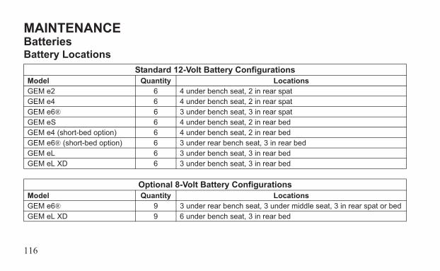
Two battery pack configurations exist for GEM vehicles. The standard configuration consists of six 12-volt batteries. An optional configuration consists of nine 8-volt batteries. See pages 116-117 for battery locations and access instructions.
116
MAINTENANCEBatteriesBattery Locations
Standard 12-Volt Battery ConfigurationsModel Quantity LocationsGEM e2 6 4 under bench seat, 2 in rear spatGEM e4 6 4 under bench seat, 2 in rear spatGEM e6® 6 3 under bench seat, 3 in rear spatGEM eS 6 4 under bench seat, 2 in rear bedGEM e4 (short-bed option) 6 4 under bench seat, 2 in rear bedGEM e6® (short-bed option) 6 3 under rear bench seat, 3 in rear bedGEM eL 6 3 under bench seat, 3 in rear bedGEM eL XD 6 3 under bench seat, 3 in rear bed
Optional 8-Volt Battery ConfigurationsModel Quantity LocationsGEM e6® 9 3 under rear bench seat, 3 under middle seat, 3 in rear spat or bedGEM eL XD 9 6 under bench seat, 3 in rear bed
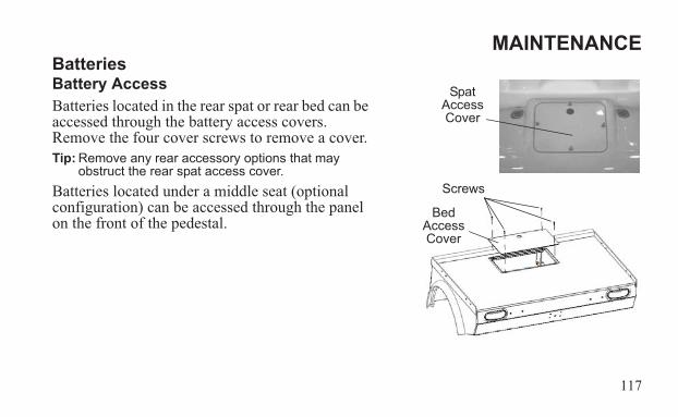
117
MAINTENANCEBatteriesBattery AccessBatteries located in the rear spat or rear bed can be accessed through the battery access covers. Remove the four cover screws to remove a cover.Tip: Remove any rear accessory options that may
obstruct the rear spat access cover.Batteries located under a middle seat (optional configuration) can be accessed through the panel on the front of the pedestal.
Spat Access Cover
Screws
Bed Access Cover
118
MAINTENANCEBatteriesBattery Inspections/MaintenancePerform the following battery inspections and maintenance procedures monthly as outlined in the Periodic Maintenance Chart beginning on page 96. Perform these operations more often for vehicles subjected to heavy use.WARNING! Do not work in or near the battery compartment or on any other electrical component of the vehicle while charging the batteries. Always turn off the main disconnect switch before servicing or unplugging any electrical components. See page 52. The main disconnect switch will disable the vehicle by disconnecting the battery pack from the motor. It does not disable the battery pack. HIGH VOLTAGE will be present at the battery terminals. HIGH BATTERY VOLTAGE IS ALWAYS PRESENT. DO NOT TOUCH THE BATTERY TERMINALS.
119
MAINTENANCEBatteriesBattery Inspections/MaintenanceCheck Battery Fluid (Flooded Batteries)Gel batteries are maintenance-free batteries. They do not have fill wells. On flooded batter-ies, check the fluid level often. Add only distilled water. Tap water contains minerals that are harmful to a battery.NOTICE: Never charge batteries if plates are exposed above the water level.Unless the plates are exposed before charging, distilled water should be added to a battery after charging. If the plates are exposed, add just enough water to cover the plates. Fully charge the batteries, then recheck the fluid level.(continued on next page)
120
MAINTENANCEBatteriesBattery Inspections/MaintenanceCheck Battery Fluid (Flooded Batteries)Maintain the fluid level between the battery plates and the bottom of the fill well. Do not overfill.WARNING! The fluid in an overfilled battery may boil over and cause electrolyte to spill.Inspect the fluid level of each battery.1. Remove one of the fill well caps.Tip: The battery plates should be visible when looking into the fill well. Use a flashlight if necessary.2. View the fluid level.Tip: If the level is below the plates, add just enough distilled water to cover the plates. Fully charge the
batteries, then recheck the fluid level.
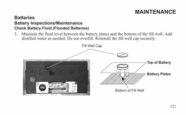
121
MAINTENANCEBatteriesBattery Inspections/MaintenanceCheck Battery Fluid (Flooded Batteries)3. Maintain the fluid level between the battery plates and the bottom of the fill well. Add
distilled water as needed. Do not overfill. Reinstall the fill well cap securely.
Bottom of Fill Well
Fill Well Cap
Top of Battery
Battery Plates

122
MAINTENANCEBatteriesBattery Inspections/MaintenanceClean the BatteriesNOTICE: Do not allow cleaning solution or tap water to enter the batteries. Before cleaning, make
sure all battery fill well caps are installed securely. 1. Remove corrosion with a stiff wire brush.2. Wash the terminals and tops of the batteries with a solution of one tablespoon baking
soda and one cup water. Rinse well with tap water and dry off with clean shop towels.3. Make sure battery terminals are tight. Use an insulated wrench to tighten as needed.4. Allow battery terminals to dry, then coat the terminals with dielectric grease or petro-
leum jelly, or spray them with battery anti-corrosion spray.
123
MAINTENANCEBatteriesBattery Inspections/MaintenanceCheck Battery ConnectionsWARNING! Improper handling of high voltage wiring, batteries or control systems could result in serious injury or death by electric shock. Only qualified technicians should repair or access high voltage wiring, battery packs and associated systems.
Check Battery Cables and WiringCheck the battery compartment for any signs of worn insulation, frayed cables or damaged cable ends. If found, see your authorized GEM dealer for service before operating.WARNING! If battery cable ends are damaged or corroded, they should be replaced or cleaned as necessary. Failure to do so may cause them to overheat during operation, possibly leading to fire, which may result in serious injury or death.
Check Battery Hold-Down BarsBattery hold-down bars should be snug to keep batteries from moving while the vehicle is in motion, but not so tight as to crack or buckle the battery case.
124
MAINTENANCEBatteriesBattery ReplacementWith proper care and maintenance, battery life could be extended up to four years or longer, depending on the amount of use. When battery replacement is necessary, please see your authorized GEM dealer.NOTICE: Always install batteries of the exact type and make originally supplied with the vehicle to
prevent damage to the vehicle’s electrical system.WARNING! Handling batteries and electrical components improperly can result in serious injury or death. Do not attempt to remove batteries or battery cables. It is essential, when replacing the cables on the batteries, that the positive cable is attached to the positive post (+) and the negative cable is attached to the negative post (-). Battery posts are identified on the battery case as positive (+) and negative (-). Always see your authorized GEM dealer for battery-related service.
125
MAINTENANCEBatteriesBattery DisposalLead-acid batteries are recyclable. Return whole scrap batteries to a distributor, manufac-turer or lead smelter for recycling. For neutralized spills, place residue in acid-resistant con-tainers with absorbent material, sand or earth and dispose of in accordance with local, state and federal regulations for acid and lead compounds. Contact local and/or state environmen-tal officials regarding disposal information. You can also contact GEM Customer Service for information. See page 5.
126
MAINTENANCEBatteriesBattery Care During StorageWARNING! Always turn off the main disconnect switch before servicing or unplugging any electrical components. See page 52. The main disconnect switch will disable the vehicle by disconnecting the battery pack from the motor. It does not disable the battery pack. HIGH VOLTAGE will be present at the battery terminals. HIGH BATTERY VOLTAGE IS ALWAYS PRESENT. DO NOT TOUCH THE BATTERY TERMINALS.
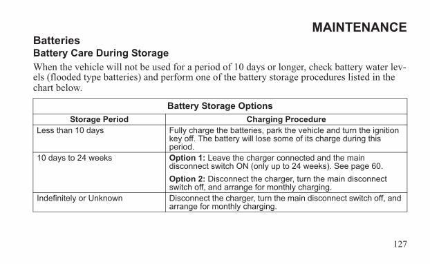
127
MAINTENANCEBatteriesBattery Care During StorageWhen the vehicle will not be used for a period of 10 days or longer, check battery water lev-els (flooded type batteries) and perform one of the battery storage procedures listed in the chart below.
Battery Storage OptionsStorage Period Charging Procedure
Less than 10 days Fully charge the batteries, park the vehicle and turn the ignition key off. The battery will lose some of its charge during this period.
10 days to 24 weeks Option 1: Leave the charger connected and the main disconnect switch ON (only up to 24 weeks). See page 60.Option 2: Disconnect the charger, turn the main disconnect switch off, and arrange for monthly charging.
Indefinitely or Unknown Disconnect the charger, turn the main disconnect switch off, and arrange for monthly charging.

128
MAINTENANCECleaning and StorageCleaning the Windshield and SunroofWe recommend using GEM Windshield Cleaner and Protectant to remove normal dust and dirt. A liquid household glass cleaner can also be used. Do not use abrasive cleaners on the windshield and sunroof, as they will cause scratches. To remove oil, grease or road tar use isopropyl alcohol, then wash the windows with water. Dry gently with a soft cloth or cham-ois.NOTICE: Be very careful when cleaning the acrylic windows (sunroof, side and rear windows) as they
can be scratched or damaged. Do not use a cleaner with an abrasive, a combination cleaner and wax or any solvent that contains ethyl or methyl alcohol. Do not use products containing ammonia, soaps, or abrasives. Never use gasoline or cleaning solvent. These products scratch or destroy the surface of the windows.
129
MAINTENANCECleaning and StorageCleaning SeatsUse GEM Foaming All Surface Cleaner to clean the seats. Rubbing seats with warm water and a clean, damp cloth will also remove dirt. Substances such as tar, asphalt and other soils will stain if not removed quickly. Use a clean cloth and solvent type vinyl cleaner, then wash the area thoroughly with a damp cloth and mild liquid detergent. Rinse with cool water.
Cleaning the InteriorUse mild liquid detergent and warm water to clean the interior. Remove detergent or deposits with a clean, damp cloth.NOTICE: Do not spray the interior of your vehicle. Liquids can damage electrical components and the
circuit board. Handle liquids with care. Do not spray water directly into the upper or lower console.
130
MAINTENANCECleaning and StorageCleaning the ExteriorThe best way to preserve your vehicle’s finish is to wash the vehicle regularly. Use GEM Fiberglass Plastic and Rubber Restorer or mild liquid detergents. Do not use strong soaps or chemical detergents. Rinse promptly. Dry the finish with a soft, clean chamois or towel to avoid surface scratches and water spotting.Tip: To prevent spotting, avoid washing the vehicle in direct sunlight.
Protection From the ElementsProlonged exposure to sunlight may deteriorate the exterior and interior finish. Park the vehi-cle in a garage or similar structure, or cover the vehicle with a GEM vehicle cover.
131
MAINTENANCECleaning and StorageStorage TipsClean the ExteriorMake any necessary repairs and clean the vehicle as recommended.
Inspect and LubricateInspect all cables and lubricate all areas of the vehicle as recommended in the Periodic Main-tenance Chart beginning on page 96.
Check Fluid LevelsInspect the fluid levels. Add or change fluids as recommended. Change brake fluid every two years and any time the fluid looks dark or contaminated.
132
MAINTENANCECleaning and StorageStoring the VehicleAny time the vehicle will be parked for more than 10 days, follow the recommended storage procedures:1. Make any necessary repairs and clean the vehicle. See page 128.2. Clean the batteries. See page 122. 3. Prepare the batteries for storage. See page 126.NOTICE: Batteries can be permanently damaged (and the warranty voided) if allowed to remain 30
days or more with low charge. Fully charge batteries before storing. In hot climates, battery self-discharge will increase. In cold climates, batteries could freeze if not properly charged.
4. Store the vehicle out of the sun in a cool, dry place.5. Be sure the storage area is well ventilated.6. Turn the key off.
133
MAINTENANCECleaning and StorageStoring the Vehicle7. Verify that tire pressure is at specification.8. Block the wheels to prevent rolling.WARNING! Do not cover the vehicle while the charger is connected. Dangerous levels of hydrogen gas could accumulate.9. If the vehicle is not connected to the charger, turn off the main disconnect switch. Cover
the vehicle with a genuine GEM vehicle cover. Do not use plastic or coated materials. They do not allow enough ventilation to prevent condensation, and may promote corro-sion and oxidation.
Removal from Storage1. Inspect all battery connections. Verify that batteries are fully charged.2. Verify that tire pressure is at specification.3. Perform the pre-ride inspection. See page 86.4. Inspect and verify the tightness of the bolts, nuts and other fasteners.
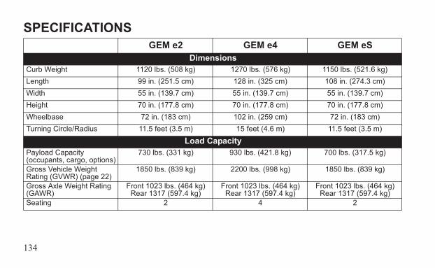
134
SPECIFICATIONSGEM e2 GEM e4 GEM eS
DimensionsCurb Weight 1120 lbs. (508 kg) 1270 lbs. (576 kg) 1150 lbs. (521.6 kg)Length 99 in. (251.5 cm) 128 in. (325 cm) 108 in. (274.3 cm)Width 55 in. (139.7 cm) 55 in. (139.7 cm) 55 in. (139.7 cm)Height 70 in. (177.8 cm) 70 in. (177.8 cm) 70 in. (177.8 cm)Wheelbase 72 in. (183 cm) 102 in. (259 cm) 72 in. (183 cm)Turning Circle/Radius 11.5 feet (3.5 m) 15 feet (4.6 m) 11.5 feet (3.5 m)
Load CapacityPayload Capacity (occupants, cargo, options)
730 lbs. (331 kg) 930 lbs. (421.8 kg) 700 lbs. (317.5 kg)
Gross Vehicle Weight Rating (GVWR) (page 22)
1850 lbs. (839 kg) 2200 lbs. (998 kg) 1850 lbs. (839 kg)
Gross Axle Weight Rating (GAWR)
Front 1023 lbs. (464 kg)Rear 1317 (597.4 kg)
Front 1023 lbs. (464 kg)Rear 1317 (597.4 kg)
Front 1023 lbs. (464 kg)Rear 1317 (597.4 kg)
Seating 2 4 2
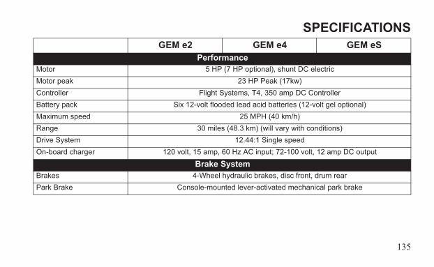
135
SPECIFICATIONSGEM e2 GEM e4 GEM eS
PerformanceMotor 5 HP (7 HP optional), shunt DC electricMotor peak 23 HP Peak (17kw)Controller Flight Systems, T4, 350 amp DC ControllerBattery pack Six 12-volt flooded lead acid batteries (12-volt gel optional)Maximum speed 25 MPH (40 km/h)Range 30 miles (48.3 km) (will vary with conditions)Drive System 12.44:1 Single speedOn-board charger 120 volt, 15 amp, 60 Hz AC input; 72-100 volt, 12 amp DC output
Brake SystemBrakes 4-Wheel hydraulic brakes, disc front, drum rearPark Brake Console-mounted lever-activated mechanical park brake
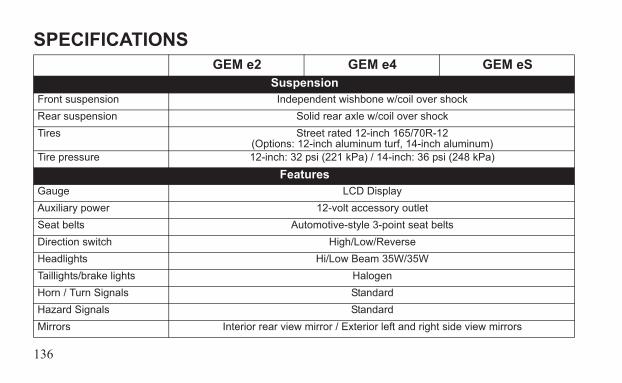
136
SPECIFICATIONSGEM e2 GEM e4 GEM eS
SuspensionFront suspension Independent wishbone w/coil over shockRear suspension Solid rear axle w/coil over shockTires Street rated 12-inch 165/70R-12
(Options: 12-inch aluminum turf, 14-inch aluminum)Tire pressure 12-inch: 32 psi (221 kPa) / 14-inch: 36 psi (248 kPa)
FeaturesGauge LCD DisplayAuxiliary power 12-volt accessory outletSeat belts Automotive-style 3-point seat beltsDirection switch High/Low/ReverseHeadlights Hi/Low Beam 35W/35WTaillights/brake lights HalogenHorn / Turn Signals StandardHazard Signals StandardMirrors Interior rear view mirror / Exterior left and right side view mirrors
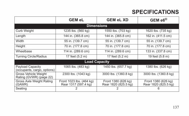
137
SPECIFICATIONSGEM eL GEM eL XD GEM e6®
DimensionsCurb Weight 1235 lbs. (560 kg) 1550 lbs. (703 kg) 1620 lbs. (735 kg)Length 144 in. (365.8 cm) 144 in. (365.8 cm) 162 in. (411.5 cm)Width 55 in. (139.7 cm) 55 in. (139.7 cm) 55 in. (139.7 cm)Height 70 in. (177.8 cm) 70 in. (177.8 cm) 70 in. (177.8 cm)Wheelbase 114 in. (289.6 cm) 114 in. (289.6 cm) 133 in. (337.8 cm)Turning Circle/Radius 17 feet (5.2 m) 17 feet (5.2 m) 19 feet (5.8 m)
Load CapacityPayload Capacity (occupants, cargo, options)
1065 lbs. (483 kg) 1450 lbs. (657.7 kg) 1380 lbs. (626 kg)
Gross Vehicle Weight Rating (GVWR) (page 22)
2300 lbs. (1043 kg) 3000 lbs. (1360.8 kg) 3000 lbs. (1360.8 kg)
Gross Axle Weight Rating (GAWR)
Front 1023 lbs. (464 kg)Rear 1317 (597.4 kg)
Front 1380 (626 kg)Rear 1820 (825.5 kg)
Front 1380 (626 kg)Rear 1820 (825.5 kg)
Seating 2 2 6
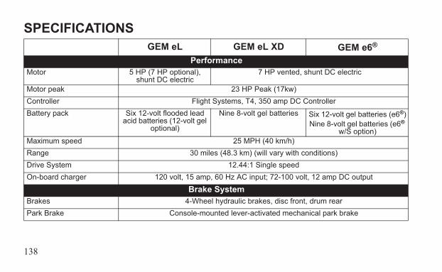
138
SPECIFICATIONSGEM eL GEM eL XD GEM e6®
PerformanceMotor 5 HP (7 HP optional),
shunt DC electric7 HP vented, shunt DC electric
Motor peak 23 HP Peak (17kw)Controller Flight Systems, T4, 350 amp DC ControllerBattery pack Six 12-volt flooded lead
acid batteries (12-volt gel optional)
Nine 8-volt gel batteries Six 12-volt gel batteries (e6®)Nine 8-volt gel batteries (e6®
w/S option)Maximum speed 25 MPH (40 km/h)Range 30 miles (48.3 km) (will vary with conditions)Drive System 12.44:1 Single speedOn-board charger 120 volt, 15 amp, 60 Hz AC input; 72-100 volt, 12 amp DC output
Brake SystemBrakes 4-Wheel hydraulic brakes, disc front, drum rearPark Brake Console-mounted lever-activated mechanical park brake
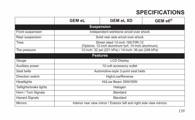
139
SPECIFICATIONSGEM eL GEM eL XD GEM e6®
SuspensionFront suspension Independent wishbone w/coil over shockRear suspension Solid rear axle w/coil over shockTires Street rated 12-inch 165/70R-12
(Options: 12-inch aluminum turf, 14-inch aluminum)Tire pressure 12-inch: 32 psi (221 kPa) / 14-inch: 36 psi (248 kPa)
FeaturesGauge LCD DisplayAuxiliary power 12-volt accessory outletSeat belts Automotive-style 3-point seat beltsDirection switch High/Low/ReverseHeadlights Hi/Low Beam 35W/35WTaillights/brake lights HalogenHorn / Turn Signals StandardHazard Signals StandardMirrors Interior rear view mirror / Exterior left and right side view mirrors
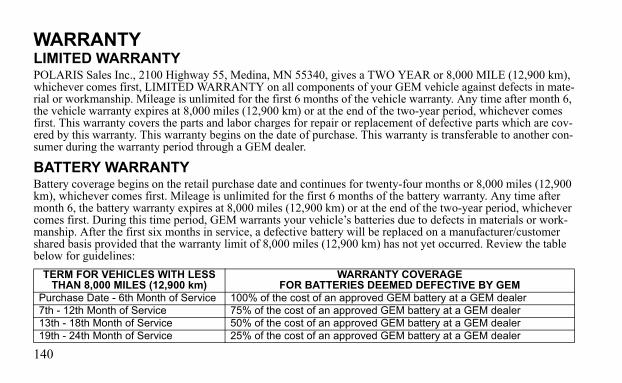
140
WARRANTYLIMITED WARRANTYPOLARIS Sales Inc., 2100 Highway 55, Medina, MN 55340, gives a TWO YEAR or 8,000 MILE (12,900 km), whichever comes first, LIMITED WARRANTY on all components of your GEM vehicle against defects in mate-rial or workmanship. Mileage is unlimited for the first 6 months of the vehicle warranty. Any time after month 6, the vehicle warranty expires at 8,000 miles (12,900 km) or at the end of the two-year period, whichever comes first. This warranty covers the parts and labor charges for repair or replacement of defective parts which are cov-ered by this warranty. This warranty begins on the date of purchase. This warranty is transferable to another con-sumer during the warranty period through a GEM dealer.
BATTERY WARRANTYBattery coverage begins on the retail purchase date and continues for twenty-four months or 8,000 miles (12,900 km), whichever comes first. Mileage is unlimited for the first 6 months of the battery warranty. Any time after month 6, the battery warranty expires at 8,000 miles (12,900 km) or at the end of the two-year period, whichever comes first. During this time period, GEM warrants your vehicle’s batteries due to defects in materials or work-manship. After the first six months in service, a defective battery will be replaced on a manufacturer/customer shared basis provided that the warranty limit of 8,000 miles (12,900 km) has not yet occurred. Review the table below for guidelines:
TERM FOR VEHICLES WITH LESS THAN 8,000 MILES (12,900 km)
WARRANTY COVERAGEFOR BATTERIES DEEMED DEFECTIVE BY GEM
Purchase Date - 6th Month of Service 100% of the cost of an approved GEM battery at a GEM dealer7th - 12th Month of Service 75% of the cost of an approved GEM battery at a GEM dealer13th - 18th Month of Service 50% of the cost of an approved GEM battery at a GEM dealer19th - 24th Month of Service 25% of the cost of an approved GEM battery at a GEM dealer
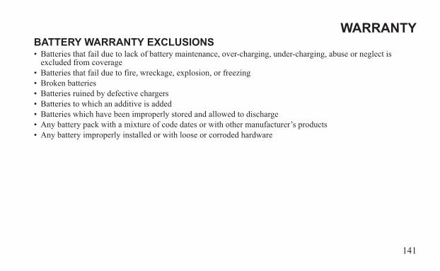
141
WARRANTYBATTERY WARRANTY EXCLUSIONS• Batteries that fail due to lack of battery maintenance, over-charging, under-charging, abuse or neglect is
excluded from coverage• Batteries that fail due to fire, wreckage, explosion, or freezing• Broken batteries• Batteries ruined by defective chargers• Batteries to which an additive is added• Batteries which have been improperly stored and allowed to discharge• Any battery pack with a mixture of code dates or with other manufacturer’s products• Any battery improperly installed or with loose or corroded hardware

142
WARRANTYLIMITATIONS OF WARRANTIES AND REMEDIESThe GEM limited warranty excludes any failures that are not caused by a defect in material or workmanship. This warranty does not cover accidental damage, normal wear and tear, abuse or improper handling. This warranty also does not cover any vehicle that has been altered structurally, modified, neglected, improperly maintained, or used for purposes other than for which it was manufactured, or for any damages which occur during trailer transit or as a result of unauthorized service or the use of unauthorized parts. In addition, this warranty does not cover physical damage to paint or finish, stress cracks, tearing or puncturing of upholstery material, corrosion, or defects in parts, components or the vehicle due to fire, explosions or any other cause beyond GEM control.The exclusive remedy for breach of this warranty shall be, at GEM’s exclusive option, repair or replacement of any defective materials, or components or products. THE REMEDIES SET FORTH IN THIS WARRANTY ARE THE ONLY REMEDIES AVAILABLE TO ANY PERSON FOR BREACH OF THIS WARRANTY. GEM SHALL HAVE NO LIABILITY TO ANY PERSON FOR INCIDENTAL, CONSEQUENTIAL OR SPECIAL DAMAGES OF ANY DESCRIPTION, WHETHER ARISING OUT OF EXPRESS OR IMPLIED WAR-RANTY OR ANY OTHER CONTRACT, NEGLIGENCE, OR OTHER TORT OR OTHERWISE THIS EXCLUSION OF CONSEQUENTIAL, INCIDENTAL, AND SPECIAL DAMAGES IS INDEPENDENT FROM AND SHALL SURVIVE ANY FINDING THAT THE EXCLUSIVE REMEDY FAILED OF ITS ESSENTIAL PURPOSE. Some states do not permit the exclusion or limitation of incidental or consequential damages or implied warranties, so the above limitations or exclusions may not apply to you if inconsistent with controlling state law.
143
WARRANTYREGISTRATIONAt the time of sale, the Warranty Registration Form must be completed by your dealer and submitted to GEM within three days. Upon receipt of this registration, GEM will record the registration for warranty. No verification of registration will be sent to the purchaser as the copy of the Warranty Registration Form will be the warranty entitlement. If you have not signed the original registration and received the customer copy, please contact your dealer immediately. NO WARRANTY COVERAGE WILL BE ALLOWED UNLESS YOUR VEHICLE IS REGISTERED WITH GEM. Initial dealer preparation and set-up of your vehicle is very important in ensuring trouble-free operation. Purchasing a machine in the crate or without proper dealer set-up will void your warranty coverage.
144
WARRANTYHOW TO OBTAIN WARRANTY SERVICEIf your vehicle requires warranty service, you must take it to a GEM Servicing Dealer. When requesting warranty service you must present your copy of the Warranty Registration form to the dealer. THE COST OF TRANS-PORTATION TO AND FROM THE DEALER IS YOUR RESPONSIBILITY. GEM suggests that you use your original selling dealer; however, you may use any GEM Servicing Dealer to perform warranty service. Please work with your dealer to resolve any warranty issues. Should your dealer require any additional assistance they will contact the appropriate person at GEM. This warranty gives you specific legal rights, and you may also have other rights which vary from state to state. If any of the above terms are void because of state or federal law, all other warranty terms will remain in effect.
Exported VehiclesEXCEPT WHERE SPECIFICALLY REQUIRED BY LAW, THERE IS NO WARRANTY OR SERVICE BUL-LETIN COVERAGE ON THIS VEHICLE IF IT IS SOLD OUTSIDE THE COUNTRY OF THE SELLING DEALER'S AUTHORIZED LOCATION.This policy does not apply to vehicles that have received authorization for export from GEM. Dealers may not give authorization for export. You should consult an authorized dealer to determine this vehicle's warranty or ser-vice bulletin coverage if you have any questions. This policy does not apply to vehicles registered to government officials or military personnel on assignment outside the country of the selling dealer's authorized location. This policy does not apply to Safety Recalls.
145
WARRANTYHow to Get ServiceIn the Country where your vehicle was purchased:Warranty or Service Bulletin repairs must be done by an authorized GEM dealer. If you move or are traveling within the country where your vehicle was purchased, Warranty or Service Bulletin repairs may be requested from any authorized GEM dealer. Outside the Country where your vehicle was purchased:If you are traveling temporarily outside the country where your vehicle was purchased, you should take your vehicle to an authorized GEM dealer. You must show the dealer photo identification from the country of the sell-ing dealer's authorized location as proof of residence. Upon residence verification, the servicing dealer will be authorized to perform the warranty repair.If You Move:If you move to another country, be sure to contact GEM Customer Assistance and the customs department of the destination country before you move. Vehicle importation rules vary considerably from country to country. You may be required to present documentation of your move to GEM in order to continue your warranty coverage. You may also be required to obtain documentation from GEM in order to register your vehicle in your new coun-try.
146
WARRANTYHow to Get ServiceIf Purchased From A Private Party:If you purchase a GEM product from a private citizen outside of the country in which the vehicle was originally purchased, all warranty coverage will be denied.
NoticeIf your vehicle is registered outside of the country where it was purchased, and you have not followed the proce-dure set out above, your vehicle will no longer be eligible for warranty or service bulletin coverage of any kind. Vehicles registered to Government officials or military personnel on assignment outside of the country where the vehicle was purchased will continue to be covered by the basic warranty.
GEM Customer ServicePhone: 855-RIDEGEM (855-743-3436)Web: www.gemcar.com
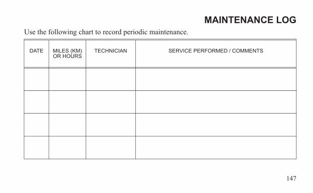
147
MAINTENANCE LOGUse the following chart to record periodic maintenance.
DATE MILES (KM)OR HOURS
TECHNICIAN SERVICE PERFORMED / COMMENTS

148
MAINTENANCE LOG
DATE MILES (KM)OR HOURS
TECHNICIAN SERVICE PERFORMED / COMMENTS
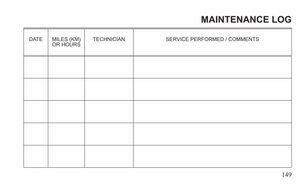
149
MAINTENANCE LOG
DATE MILES (KM)OR HOURS
TECHNICIAN SERVICE PERFORMED / COMMENTS
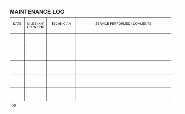
150
MAINTENANCE LOG
DATE MILES (KM)OR HOURS
TECHNICIAN SERVICE PERFORMED / COMMENTS
151
INDEXA
Accelerator Pedal . . . . . . . . . . . . . 55Accessory Backs . . . . . . . . . . . . 77-79Accessory Outlet, 12-Volt . . . . . . 69
BBatteries . . . . . . . . . . 58-68, 113-127
Access . . . . . . . . . . . . . . . . . . 117Battery Pack. . . . . . . . . . . . . . . 58Care During Storage . . . . 126-127Charging . . . . . . . . . . . . . . . 61-64Charging, Alternate Method 65-66Cleaning. . . . . . . . . . . . . . . . . 122Configurations . . . . . . . . . . . . 115Disposal . . . . . . . . . . . . . . . . . 125Fluid. . . . . . . . . . . . . . . . . 119-121Handling Precautions. . . . . . 67-68Inspections. . . . . . . . . . . . 118-123Locations . . . . . . . . . . . . . . . . 116Monthly Maintenance . . . 118-123On-Board Charger . . . . . . . . . . 60Performance Tips. . . . . . . . . . . 59Replacement . . . . . . . . . . . . . 124
BBattery Discharge Indicator . . . 48-49Brake Lever, Park . . . . . . . . . . 56-57Brake Lights . . . . . . . . . . . . . . . . . 110Brake Pedal . . . . . . . . . . . . . . . . . . 54Brakes . . . . . . . . . . . . . . . . . . 98-100
Brake Fluid . . . . . . . . . . . . . 98-99Brake Inspection . . . . . . . . . . . 100
Bumpers, Optional . . . . . . . . . . . . . 80
CCargo Carrier, Enclosed. . . . . . . . . 82Cleaning
Exterior . . . . . . . . . . . . . . . . . . 130Interior . . . . . . . . . . . . . . . . . . 129Seats . . . . . . . . . . . . . . . . . . . . 129Windshield and Sunroof . . . . . 128
Cleaning and Storage . . . . . . 128-133Console. . . . . . . . . . . . . . . . . . . 32-53Customer Service . . . . . . . . . . . 5, 146
DDirection Switch . . . . . . . . . . . . 40-41Dome Light . . . . . . . . . . . . . . . . . . 68Doors . . . . . . . . . . . . . . . . . . . . . . . 81Driving in Reverse . . . . . . . . . . . . 90Driving on Slippery Surfaces . . . . 91Driving Procedure . . . . . . . . . . . 88-89
EElectrical Components . . . . . . . . . 33E-Meter . . . . . . . . . . . . . . . . . . . 38-39Equipment Modifications . . . . . . . 24
FFluid Levels During Storage . . . . 131Fluid, Battery. . . . . . . . . . . . . 119-121Fluid, Brake. . . . . . . . . . . . . . . . 98-99Fuse Recommendations . . . . . . . 103Fuse Replacement . . . . . . . . . 102-103
152
INDEXG
Glove Box . . . . . . . . . . . . . . . . . . . 35Grab Handle Package . . . . . . . . . . . 82Gross Vehicle Weight Rating. . 22-23
HHazard Signals . . . . . . . . . . . . . . . . 53Headlight Beam Adjustment 111-112Headlight Replacement . . . . . . . . 109Headlight Switch . . . . . . . . . . . . . . 33Heater/Defogger . . . . . . . . . . . . . . . 84Horn . . . . . . . . . . . . . . . . . . . . . . . . 35
KKey Switch . . . . . . . . . . . . . . . . . . . 34
LLCD Display Indicators. . . . . . 42-51Lights . . . . . . . . . . . . . . . . . 109-112
Brake Lights . . . . . . . . . . . . . . 110Dome Light . . . . . . . . . . . . . . . 68Front Turn Signal . . . . . . . . . . 109Headlight Adjustment . . 111-112Headlight Replacement . . . . . 109Rear Turn Signal . . . . . . . . . . 110
MMain Disconnect Switch . . . . . 52-53Maintenance Precautions. . . . . . . . 31Maintenance, Periodic . . . . . . . 96-97Manufacturer’s Label . . . . . . . . 9-11Modifications. . . . . . . . . . . . . . . . . 24
OOdometer . . . . . . . . . . . . . . . . . 38-39On-Board Charger . . . . . . . . . . . . . 60Operator Safety . . . . . . . . . . . . 17-31
PPark Brake Lever . . . . . . . . . . . 56-57Parking on an Incline . . . . . . . . . . . 93Parking the Vehicle . . . . . . . . . . . . 92Periodic Maintenance Chart . . . 96-97Pre-Ride Inspection . . . . . . . . . 86-87
RRear Accessory Backs . . . . . . . 77-79Removing Vehicle from Storage . 133Reverse Operaton . . . . . . . . . . . . . . 90
SSafety Labels . . . . . . . . . . . . . . 12-16Safety Symbols . . . . . . . . . . . . . . . . . 7Seat Adjustment . . . . . . . . . . . . . . . 70Seat Belt Inspection . . . . . . . . . . . . 75Seat Belt Safety Tips . . . . . . . . . . . 74Seat Belt, Proper Use . . . . . . . . 72-73Seat Belts . . . . . . . . . . . . . . . . . 71-75
153
INDEXS
Seat Removal, Bench . . . . . . . . . . 70Signal Words. . . . . . . . . . . . . . . . . . 7State of Charge Indicator . . . . . 48-49Steering Column Lock . . . . . . . . . 83Steering Column, Adjustable Tilt . 84Steering Wheel Inspection . . . . . 101Stereo System . . . . . . . . . . . . . . . . 76Storage . . . . . . . . . . . . . . . . . 128-133Storage Tips . . . . . . . . . . . . . . . . 131Storage, Removal . . . . . . . . . . . . 133Storing the Vehicle . . . . . . . . 132-133Switches
Direction Switch . . . . . . . . . 40-41Headlight Switch . . . . . . . . . . . 33Key Switch . . . . . . . . . . . . . . . 34Main Disconnect Switch . . . 52-53
TTires . . . . . . . . . . . . . . . . . . . 104-108
Tire Pressure . . . . . . . . . . . . . . 104Tread Depth . . . . . . . . . . . . . . 105Wheel Installation. . . . . . . . . . 108Wheel Nut Torque . . . . . . . . . 105Wheel Removal . . . . . . . 106-107
Transporting the Vehicle . . . . . 94-95Trip Meter . . . . . . . . . . . . . . . . 38-39Turn Signal. . . . . . . . . . . . . . . . . . . 36Turn Signal Light Replacement
Front . . . . . . . . . . . . . . . . . . . . 109Rear. . . . . . . . . . . . . . . . . . . . . 110
VVehicle Information Label . . . . . 9-11
WWarning Symbols . . . . . . . . . . . . . . 7Washing,Windshield & Sunroof . 128Weight Capacity . . . . . . . . . . . . 22-23Wheel Installation . . . . . . . . . . . . 108Wheel Nut Torque. . . . . . . . . . . . 105Wheel Removal . . . . . . . . . . . 106-107Windshield Washer . . . . . . . . . . . . 85Windshield Wiper . . . . . . . . . . . . . 37
ZZero Speed Detection Feature . . . . 35

For your nearest GEM dealer, call 855-RIDEGEM (855-743-3436)or visit www.gemcar.comPolaris Sales Inc.2100 Hwy. 55Medina, MN 55340
Part No. 9924250 Rev 02Printed in USA