Embed Size (px)
Citation preview
LM2717,LM3370,LP3971,LP5900
Optimizing Power Management Solutions for Advanced Applications Processors
Literature Number: SNVA539
Optimizing Power Management Solutions for Advanced Applications Processors
ANALOG edge SM
by Ken Marasco, System Architect
Power management solutions for today’s portable applicationsprocessors are becoming highly integrated. Total power consumption, standby, and deep-sleep current consumptioneffect battery size, bill-of-material cost, and product acceptance. System designers must consider many variations ofpower supplies when designing portable devices such as smartphones or PDAs. Smart phones are becoming more powerhungry and require highly-integrated power managementsolutions to meet the overall design requirements of maximumbattery life in the smallest PCB area possible. Today’s applica-tions processors require separate power domains for the core,IOs, memory, and peripherals. The LP3971 is a flexible PowerManagement Unit (PMU) designed to meet all of these require-ments utilizing three high-efficiency buck converters and sixLDOs. Applications processors require multiple power-supply voltages, which can be optimized as demanded by the core
power manager and system architecture. The LP3971 meets thewide range of system requirements with I2C-controlled outputvoltages, and factory-configurable power-on sequencing, anddefault output voltages. This design idea will focus on power-ing a microprocessor’s low voltage rail using the LP3971 buckconverter and LDO for a PDA or smart phone application.
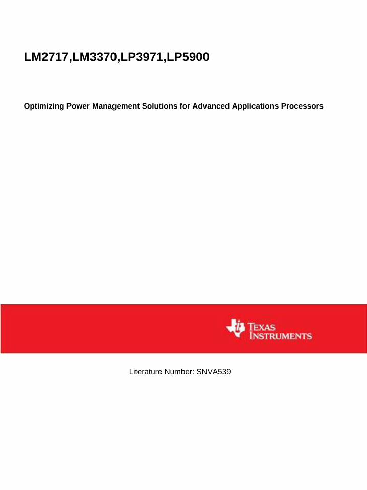
When designing a system, the architect must balance an oceanof requirements such as cost, PCB area, component size, talktime, standby time, battery capacity, and schedule. The microprocessor RAM requires a 1.5V supply with a maximumcurrent of 400 mA. Let’s start with the simplest, lowest costsolution, a Low Dropout (LDO) regulator connected directlyto the Lithium-Ion (Li-Ion) battery as shown in Figure 1. Thebattery voltage will start at 4.2V and decrease to 3.2V, wherethe system enters into deep sleep until the battery is recharged orreplaced. Figure 2 shows a typical Li-Ion battery discharge cycle.
For the configuration shown in Figure 1, the efficiency ofLDO 5 will be:
LDO% Efficiency = [(VOUT * IOUT) / VIN * (IOUT + Iq)] * 100
For this and all other examples in this article, Iq is removedbecause it is very low (40 µA) compared with IOUT (400 mA).
The efficiency equation then becomes:
% Efficiency = [(VOUT) / (VIN)] * 100
For VIN = 4.2V and VOUT = 1.5V, the LDO efficiency is1.5/4.2 = 36%.
Total power (PT) = 4.2 * 0.400 = 1.70W
All power that is not delivered to the output load is dissipatedas heat within the LDO. Dissipated power is estimated as:
Dissipated power (PD) = (VIN - VOUT) * IOUT = (4.2 - 1.5) * 0.400 = 1.1W
will be dissipated as heat.
ideaDESIGNVol. IV, Issue 2
Expert tips, tricks, and techniques for analog designs
NEXT ISSUE: Digital Down Conversion
VCC_PLL
VCC_USB
Digital Supply
Digital SupplyApplications
Processor
VCC_RAM
LDO 1
LDO 2
LDO 3
LDO 4
LDO 5V0 = 1.5V
VBATT
Back-UpBattery
BUCHG_EN
LDO RTC/Batt SW
I2C
Power On
VCC_MEM
BUCK 2
BUCK 1
BUCK 31.8V
VCC_IO
VCC_Core
VCC_RTC
SCL & SDA
VCC_AUX 1
VCC_AUX 2
Figure 1. LD0 5 Connected Directly to Main Battery
AnalogEdge_V4_Issue2 1/16/06 2:28 PM Page 1
Dual Step-Down Converter For Portable Systemswith Complex Power Management RequirementsThe LM3370 is a dual step-down DC-DC converter optimized forpowering ultra-low voltage circuits from a single Li-Ion battery andinput rail ranging from 2.7V to 5.5V. It provides two outputs with600 mA load per channel. The output voltage range varies from 1Vto 3.3V and can be dynamically controlled using the I2C-compatibleinterface. This dynamic voltage scaling function allows processors toachieve maximum performance at the lowest power level. The I2C-compatible interface can also be used to control auto PFM-PWM/PWM mode selection and other performance enhancing features.
The LM3370 features automatic intelligent switching betweenPWM low-noise and PFM low-current mode, offering improvedsystem efficiency. And an internal synchronous rectificationenhances the converter efficiency without the use of further external devices.
Features I2C-compatible interface
– VOUT1 = 1V to 2V in 50 mV steps – VOUT2 = 2.3V to 3.3V in 100 mV steps – Automatic PFM/PWM mode switching and forced PWM
mode for low noise operation – Spread spectrum capability using I2C
600 mA load per channel 2 MHz PWM fixed switching frequency (typ) Internal synchronous rectification for high efficiency Internal soft-start Power-on-reset function for both outputs Operates from a single Li-Ion cell or 3-cell NiMH/NiCd
battery and 3.3V/5.5V fixed rails
The LM3370 is ideal for applications such as baseband processors,application processors (i.e. video and audio), I/O power, and FPGApower and CPLD. The LM3370 is offered in a tiny (4 mm x 5 mm x0.8 mm) LLP-16 package.
www.national.com/pf/LM/LM3370.html
Power Management Unit for AdvancedApplications ProcessorsThe LP3971 is a multi-function, programmable power managementIC, designed especially for advanced applications processors. Thisdevice is optimized for low-power handheld applications andprovides six low-dropout, low-noise linear regulators, three DC-DCmagnetic buck regulators, a backup battery charger, and twoGPOs. A high-speed serial interface is included to program individual regulator output voltages as well as on/off control.
Features 1.6A Output on three high-efficiency buck regulators with
voltage scaling Five LDOs for powering peripherals and I/Os with voltage
scaling, and a sixth LDO dedicated as a RTC LDO I2C-compatible, high-speed serial interface for software
control of regulator functions and settings Backup battery charger
The LP3971 is ideal for applications such as PDA and smartphones, personal media players, digital cameras, point-of-sale/barcode scanners, and for powering applications processorssuch as Intel’s Xscale, and other application processors. TheLP3971 is offered in a tiny (5 mm x 5 mm) LLP-40 package.
www.national.com/pf/LP/LP3971.html
Featured Products
edge.national.com
AnalogEdge_V4_Issue2 1/16/06 2:28 PM Page 2
We have just calculated the maximum continuous power (PT).The RAM will not operate at this level for very long. If we lookat a 10% duty cycle, the average power consumption will be:
PT = 0.10 * 1.7 = 0.17W
The amount of time the RAM operates at IMAX is dependentupon the application, power management firmware, and theoperating system.
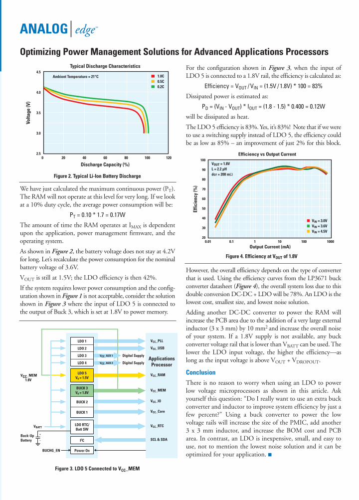
As shown in Figure 2, the battery voltage does not stay at 4.2Vfor long. Let’s recalculate the power consumption for the nominalbattery voltage of 3.6V.
VOUT is still at 1.5V; the LDO efficiency is then 42%.
If the system requires lower power consumption and the config-uration shown in Figure 1 is not acceptable, consider the solutionshown in Figure 3 where the input of LDO 5 is connected tothe output of Buck 3, which is set at 1.8V to power memory.
For the configuration shown in Figure 3, when the input ofLDO 5 is connected to a 1.8V rail, the efficiency is calculated as:
Efficiency = VOUT / VIN = (1.5V / 1.8V) * 100 = 83%
Dissipated power is estimated as:
PD = (VIN - VOUT) * IOUT = (1.8 - 1.5) * 0.400 = 0.12W
will be dissipated as heat.
The LDO 5 efficiency is 83%. Yes, it’s 83%! Note that if we wereto use a switching supply instead of LDO 5, the efficiency couldbe as low as 85% – an improvement of just 2% for this block.
However, the overall efficiency depends on the type of converterthat is used. Using the efficiency curves from the LP3671 buckconverter datasheet (Figure 4), the overall system loss due to thisdouble conversion DC-DC + LDO will be 78%. An LDO is thelowest cost, smallest size, and lowest noise solution.
Adding another DC-DC converter to power the RAM willincrease the PCB area due to the addition of a very large externalinductor (3 x 3 mm) by 10 mm2 and increase the overall noiseof your system. If a 1.8V supply is not available, any buck converter voltage rail that is lower than VBATT can be used. Thelower the LDO input voltage, the higher the efficiency—aslong as the input voltage is above VOUT + VDROPOUT.
Conclusion
There is no reason to worry when using an LDO to powerlow voltage microprocessors as shown in this article. Askyourself this question: “Do I really want to use an extra buckconverter and inductor to improve system efficiency by just afew percent?” Using a buck converter to power the low voltage rails will increase the size of the PMIC, add another3 x 3 mm inductor, and increase the BOM cost and PCBarea. In contrast, an LDO is inexpensive, small, and easy touse, not to mention the lowest noise solution and it can beoptimized for your application.
0 20 40 60 80 100 1202.5
3.0
3.5
4.0
4.5Typical Discharge Characteristics
Volta
ge (V
)
Discharge Capacity (%)
Ambient Temperature = 21°C 1.0C0.5C0.2C
Figure 2. Typical Li-Ion Battery Discharge
ANALOG edge SM
Optimizing Power Management Solutions for Advanced Applications Processors
20
40
60
80
30
50
70
90
100
Effic
ienc
y (%
)
0.01 0.1 1 10 100 1000Output Current (mA)
Efficiency vs Output Current
VOUT = 1.8VL = 2.2 µHdcr = 200 mΩ
VIN = 3.0VVIN = 3.6VVIN = 4.5V
Figure 4. Efficiency at VOUT of 1.8V
VCC_PLL
VCC_USB
ApplicationsProcessor
VCC_RAM
LDO 1
LDO 2
LDO 3
LDO 4
LDO 5V0 = 1.5V
VBATT
VCC_MEM1.8V
Back-UpBattery
BUCHG_EN
LDO RTC/Batt SW
I2C
Power On
VCC_MEM
BUCK 2
BUCK 1
BUCK 3V0 = 1.8V
VCC_IO
VCC_Core
VCC_RTC
SCL & SDA
Digital Supply
Digital Supply
VCC_AUX 1
VCC_AUX 2
Figure 3. LDO 5 Connected to VCC_MEM
AnalogEdge_V4_Issue2 1/16/06 2:28 PM Page 3

Featured Products
570102-030
© National Semiconductor Corporation, 2006. National Semiconductor, , and LLP are registered trademarks and Analog Edge is a service mark of NationalSemiconductor Corporation. All other brand or product names are trademarks or registered trademarks of their respective holders.
Dual Step-Down DC-DC Converter Features>90% Efficiency Over a Wide Load RangeThe LM2717 is composed of two PWM DC-DC buck (step-down)converters. The first converter is used to generate a fixed outputvoltage of 3.3V, and is available in an adjustable version. The second converter is used to generate an adjustable output voltage.Both converters feature low RDSON (0.16W) internal switches formaximum efficiency. Operating frequency can be adjusted anywhere between 300 kHz and 600 kHz, allowing the use of smallexternal components. External soft-start pins for each deviceenable the user to tailor the soft-start times to a specific applica-tion. Each converter may also be shut down independently with itsown shutdown pin.
Features Fixed 3.3V output buck converter with a 2.2A, 0.16W
internal switch Adjustable buck converter with a 3.2A, 0.16W internal switch Operating input voltage range of 4V to 20V Input undervoltage protection 300 kHz to 600 kHz pin-adjustable operating frequency Over-temperature protection
The LM2717 is well suited for a variety of applications where multiplehigh-current, low-voltage power supplies are needed to power systemloads, including disk drives, DSP power supplies, DSL and cablemodems, TFT-LCD displays, set-top boxes, handheld devices, laptopcomputers, and other portable applications. The LM2717 is availablein a low-profile TSSOP-24 package.
www.national.com/pf/LM/LM2717.html
Miniature, Ultra-Low Noise, 100 mA LinearRegulator for Analog and RF Signal-Path ICs The LP5900 is a miniature CMOS linear regulator capable of supply-ing 100 mA output current. Designed to meet the requirements ofRF and analog circuits, the LP5900 provides low noise, high PSRR,low quiescent current, and low line transient response. Using apatent-pending design, the LP5900 offers class-leading devicenoise performance without the use of a bypass capacitor. Thedevice is designed to work with 0.47 µF input and output ceramiccapacitors and is available in multiple output voltages from 1.5Vto 3.3V, including 1.8V, 2.0V, 2.2V, 2.5V, 2.7V, 2.8V, 3.0V, and 3.3V.
Features 6.5 µVrms of noise combined with 85 dB of PSRR ensures
signal integrity 25 µA of quiescent current extends battery life in
portable devices 80 mV Dropout improves system efficiency ±2% Output voltage accuracy over full line/load/temp Thermal-overload and short-circuit protection -40°C to +125°C junction temperature range
The LP5900 is ideal for use in cellular phones, PDA handsets, andwireless LAN devices. This linear regulator is available in LLP-6and micro SMD-4 packaging.
www.national.com/pf/LP/LP5900.html
AnalogEdge_V4_Issue2 1/16/06 2:28 PM Page 4
IMPORTANT NOTICE
Texas Instruments Incorporated and its subsidiaries (TI) reserve the right to make corrections, modifications, enhancements, improvements,and other changes to its products and services at any time and to discontinue any product or service without notice. Customers shouldobtain the latest relevant information before placing orders and should verify that such information is current and complete. All products aresold subject to TI’s terms and conditions of sale supplied at the time of order acknowledgment.
TI warrants performance of its hardware products to the specifications applicable at the time of sale in accordance with TI’s standardwarranty. Testing and other quality control techniques are used to the extent TI deems necessary to support this warranty. Except wheremandated by government requirements, testing of all parameters of each product is not necessarily performed.
TI assumes no liability for applications assistance or customer product design. Customers are responsible for their products andapplications using TI components. To minimize the risks associated with customer products and applications, customers should provideadequate design and operating safeguards.
TI does not warrant or represent that any license, either express or implied, is granted under any TI patent right, copyright, mask work right,or other TI intellectual property right relating to any combination, machine, or process in which TI products or services are used. Informationpublished by TI regarding third-party products or services does not constitute a license from TI to use such products or services or awarranty or endorsement thereof. Use of such information may require a license from a third party under the patents or other intellectualproperty of the third party, or a license from TI under the patents or other intellectual property of TI.
Reproduction of TI information in TI data books or data sheets is permissible only if reproduction is without alteration and is accompaniedby all associated warranties, conditions, limitations, and notices. Reproduction of this information with alteration is an unfair and deceptivebusiness practice. TI is not responsible or liable for such altered documentation. Information of third parties may be subject to additionalrestrictions.
Resale of TI products or services with statements different from or beyond the parameters stated by TI for that product or service voids allexpress and any implied warranties for the associated TI product or service and is an unfair and deceptive business practice. TI is notresponsible or liable for any such statements.
TI products are not authorized for use in safety-critical applications (such as life support) where a failure of the TI product would reasonablybe expected to cause severe personal injury or death, unless officers of the parties have executed an agreement specifically governingsuch use. Buyers represent that they have all necessary expertise in the safety and regulatory ramifications of their applications, andacknowledge and agree that they are solely responsible for all legal, regulatory and safety-related requirements concerning their productsand any use of TI products in such safety-critical applications, notwithstanding any applications-related information or support that may beprovided by TI. Further, Buyers must fully indemnify TI and its representatives against any damages arising out of the use of TI products insuch safety-critical applications.
TI products are neither designed nor intended for use in military/aerospace applications or environments unless the TI products arespecifically designated by TI as military-grade or "enhanced plastic." Only products designated by TI as military-grade meet militaryspecifications. Buyers acknowledge and agree that any such use of TI products which TI has not designated as military-grade is solely atthe Buyer's risk, and that they are solely responsible for compliance with all legal and regulatory requirements in connection with such use.
TI products are neither designed nor intended for use in automotive applications or environments unless the specific TI products aredesignated by TI as compliant with ISO/TS 16949 requirements. Buyers acknowledge and agree that, if they use any non-designatedproducts in automotive applications, TI will not be responsible for any failure to meet such requirements.
Following are URLs where you can obtain information on other Texas Instruments products and application solutions:
Products Applications
Audio www.ti.com/audio Communications and Telecom www.ti.com/communications
Amplifiers amplifier.ti.com Computers and Peripherals www.ti.com/computers
Data Converters dataconverter.ti.com Consumer Electronics www.ti.com/consumer-apps
DLP® Products www.dlp.com Energy and Lighting www.ti.com/energy
DSP dsp.ti.com Industrial www.ti.com/industrial
Clocks and Timers www.ti.com/clocks Medical www.ti.com/medical
Interface interface.ti.com Security www.ti.com/security
Logic logic.ti.com Space, Avionics and Defense www.ti.com/space-avionics-defense
Power Mgmt power.ti.com Transportation and Automotive www.ti.com/automotive
Microcontrollers microcontroller.ti.com Video and Imaging www.ti.com/video
RFID www.ti-rfid.com
OMAP Mobile Processors www.ti.com/omap
Wireless Connectivity www.ti.com/wirelessconnectivity
TI E2E Community Home Page e2e.ti.com
Mailing Address: Texas Instruments, Post Office Box 655303, Dallas, Texas 75265Copyright © 2011, Texas Instruments Incorporated