Embed Size (px)
Citation preview
` 3
Manufacturing of Cut Resistant Gloves
1. Introduction
The world market demand of all categories of protective gloves including cut resistant is
increasing day by day. Total annual worldwide demand of protective gloves is estimated
near about 13.5 billion pairs. Demand of protective gloves split among Europe, North
America, Asia and rest of the world is about 20 to 30% of total consumption.
Accidents involving the use of sharp objects make up a significant percentage of injuries
in the workplace (the exact percentage varies from industry to industry; with shop-floor
workers are most likely to suffer injuries of this nature). More than 80 percent of all hand
injuries are due to cuts. Most of which can be traced to an absence of gloves, that’s why
there is a good demand of protective gloves that not only resist cuts, but are also
comfortable to wear, ensuring compliancy as well as safety.
Glove manufacturers are continually looking for new and ingenious combinations of
materials to achieve the greatest protection possible, whilst still allowing the wearer
enough dexterity to perform the intended activity. Generally, Dyneema and Spectra,
glove can be used for protection against higher levels of risks against cut and puncture
hazards. It has been seen that gloves made from Dyneema/nylon blended yarn can
provide high level of protection against cuts with good wearing comfort. This report
suggests the Dyneema/nylon blended yarns for gloves materials & seamless gloves
knitting machine for gloves manufacturing.
The use of yarns with high cut-resistance properties in knitted gloves, including some
that are woven with stainless steel wire threads, have proved to be of great benefit. The
aim of proposed project is to develop cut resistant & abrasion resistant protective textile
by using composite metallic yarn. To study the cut resistant & abrasion resistant
properties of protective textile 60 micron steel filament has been used as a core and
nylon, polyester and cotton fibers, are used as sheath fibers to cover the steel filament
and was spun into 10s count yarn on DREF machine and tested for their physical
` 4
properties. The knitted gloves and woven fabrics were prepared by using these yarns,
and were tested for their physical, cut & abrasion resistant properties. Techno economic
viability of the developed products has also been worked out.
1.1 Demand & Supply
In 2006, total industrial demand for protective gloves amounted to € 1,972 million. The
market size grew 2.9% annually during the period 2003-2008 and a further growth of the
same level is expected in 2009 and 20011.
The share of developing country imports increased 20% (in absolute terms) to 68% of
the EU imported value of protective gloves in the period 2005-2007 and accounted for
95% of imports from outside the EU in 2007. Developing countries, in particular Asian
countries dominate EU imports of protective gloves. Malaysia and China (each country
21% of total imports) remained by far the most important suppliers of protective gloves,
followed by Thailand (8%), India and Sri Lanka. China dominates EU imports of
protective gloves, made of leather, textiles and plastic.
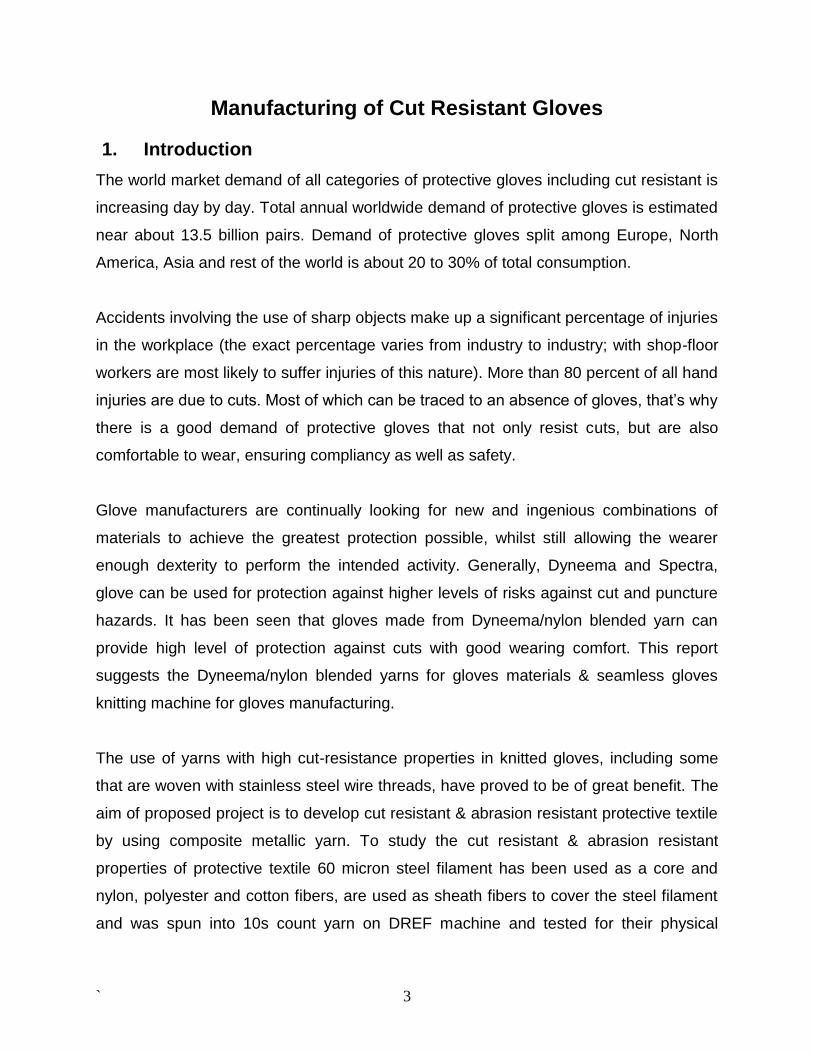
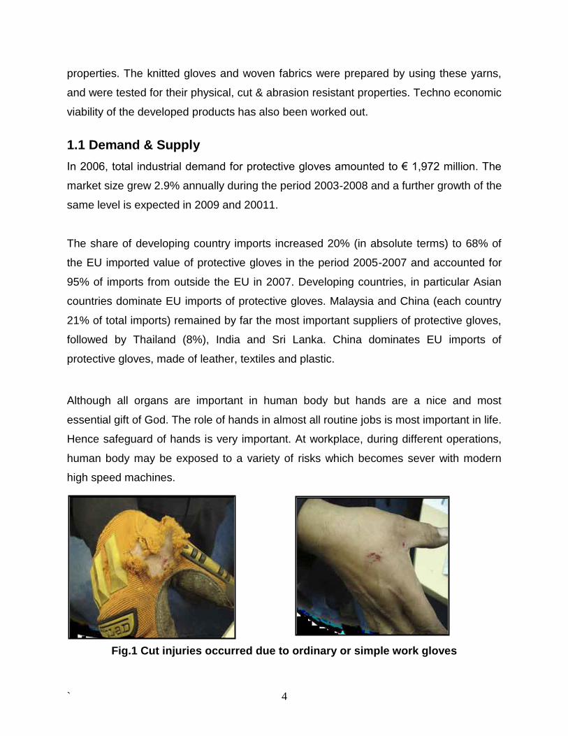
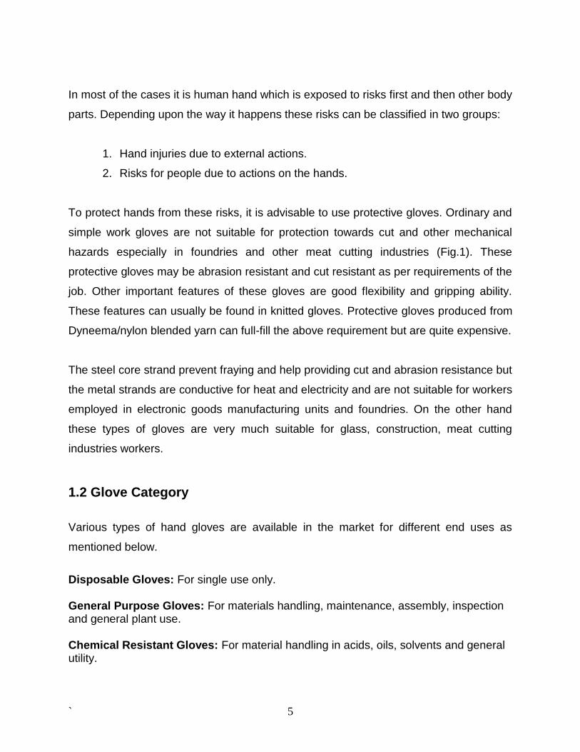
Although all organs are important in human body but hands are a nice and most
essential gift of God. The role of hands in almost all routine jobs is most important in life.
Hence safeguard of hands is very important. At workplace, during different operations,
human body may be exposed to a variety of risks which becomes sever with modern
high speed machines.
Fig.1 Cut injuries occurred due to ordinary or simple work gloves
` 5
In most of the cases it is human hand which is exposed to risks first and then other body
parts. Depending upon the way it happens these risks can be classified in two groups:
1. Hand injuries due to external actions.
2. Risks for people due to actions on the hands.
To protect hands from these risks, it is advisable to use protective gloves. Ordinary and
simple work gloves are not suitable for protection towards cut and other mechanical
hazards especially in foundries and other meat cutting industries (Fig.1). These
protective gloves may be abrasion resistant and cut resistant as per requirements of the
job. Other important features of these gloves are good flexibility and gripping ability.
These features can usually be found in knitted gloves. Protective gloves produced from
Dyneema/nylon blended yarn can full-fill the above requirement but are quite expensive.
The steel core strand prevent fraying and help providing cut and abrasion resistance but
the metal strands are conductive for heat and electricity and are not suitable for workers
employed in electronic goods manufacturing units and foundries. On the other hand
these types of gloves are very much suitable for glass, construction, meat cutting
industries workers.
1.2 Glove Category
Various types of hand gloves are available in the market for different end uses as
mentioned below.
Disposable Gloves: For single use only. General Purpose Gloves: For materials handling, maintenance, assembly, inspection and general plant use. Chemical Resistant Gloves: For material handling in acids, oils, solvents and general utility.
` 6
Heat Resistant Gloves: For material handling in hot objects, molten metal, plastic extrusion and heat treating industries.
Cut Resistant Gloves: For handling sharp‐edged objects, glass or scrap metal and
cutting applications.
1.2.1 Understanding Cut Resistance Cuts, slices and abrasions account for almost 30% of the lost time and productivity.
Most of these (almost 80%) involve hands. Makings sense of cut resistance, however,
continues to an allusive task. Knowing the actual level of cut resistance is further
complicated by the fact that many glove manufacturers make claims about the level of
cut‐resistance without having any third party documentation to back up the claims.
Types of Cuts - Most of the hand injuries occur because of reasons mentioned below:
Slicing – Caused by the sliding of the skin across a very sharp edge. The sliding action
can be a result of the hand or other skin surface sliding across the sharp edge or by the
sharp edge sliding across the stationary hand or other skin surface. Examples of this
type of cut would be a slip of the knife when dicing vegetables.
Abrasions – This type of cut is the result of continuous or repeated “rubbing”. The
surface may or may not be sharp or jagged.
Punctures or impact cuts – These are the result sharp or pointed objects impacting
the skin as in a falling pane of glass or sheet of metal. Needle sticks would also fall into
this category.
1.2.2 Selection of Cut Resistant Glove
Cut‐resistant gloves are designed to protect hands from direct contact with sharp edges
such as glass, metal, ceramics and other materials. Cut‐resistance is a function of a
glove’s material composition and thickness. You can increase your cut protection by
` 7
increasing material weight (i.e. ounces per square yard), using high‐performance
materials such as Spectra®, Kevlar®, etc., or by using composite yarns made with
varying combinations of stainless steel, fiberglass, synthetic yarns and
high‐performance yarns.
Performance characteristics can also be affected by a materials weight and coatings
applied to the outside surface. Lighter weight styles are typically more flexible, resulting
in less hand fatigue, while their heavier counterparts will generally provide the wearer
with more cut and abrasion protection. Coated gloves enhance grip, especially on
slippery surfaces. However, some coated gloves may not be appropriate for food
handling applications. The cut resistance gloves are manufactured using different type
of fibers for various end uses.
• Spectra Fiber ‐ Ultrahigh molecular‐weight polyethylene fiber that offers high
cut‐resistance, even when wet. It’s 10 times stronger than steel per unit weight. Spectra
gloves are cut and abrasion resistant, often lightweight, flexible and used for food
processing, appliance assembly, food service, automotive assembly and the paper
industry.
• Dyneema® ‐ is a super strong polyethylene fiber that offers maximum strength
combined with minimum weight. It is up to 15 times stronger than quality steel and up to
40% stronger than aramid fibers, both on weight for weight basis. Dyneema® floats on
water and is extremely durable and resistant to moisture, UV light and chemicals.
• Kevlar® Aramid Fiber ‐ five times stronger than steel per unit weight. Inherently flame
resistant it begins to char at 800°F (427°C). The thread made of Kevlar fiber is used to
sew seams on temperature‐resistant gloves. Kevlar gloves offer cut‐ and
heat‐resistance. Typically a lightweight flexible material that is used for many
applications relating to automotive assembly, sheet metal handling and glass handling.
• Fiber‐Metal Blends ‐ many durable, abrasion‐resistant gloves are made of a woven
fabric blend of Spectra, Kevlar and stainless steel.
` 8
• Metal Mesh ‐ interlocked stainless steel mesh offers superior cut and puncture
protection due to its strength. Metal Mesh gloves are very cut‐ and abrasion‐resistant
and are used often in meat/poultry applications.
• Super Fabric® ‐ Combinations of the number of layers, thickness, substrates, surface
coatings, etc., lead to fabrics which have varying levels of puncture, cut and abrasion
resistance, grip and flexibility. Tactile surface offers improved grip of wet and oily
surfaces.
• Steel Core gloves are cut‐ and abrasion‐resistant and are often used for meat/poultry
processing, glass handling, metal fabrication, automotive manufacturing as well as
being used in the paper industry.
1.3 Manufacturing Process
1.3.1 Knitting of gloves
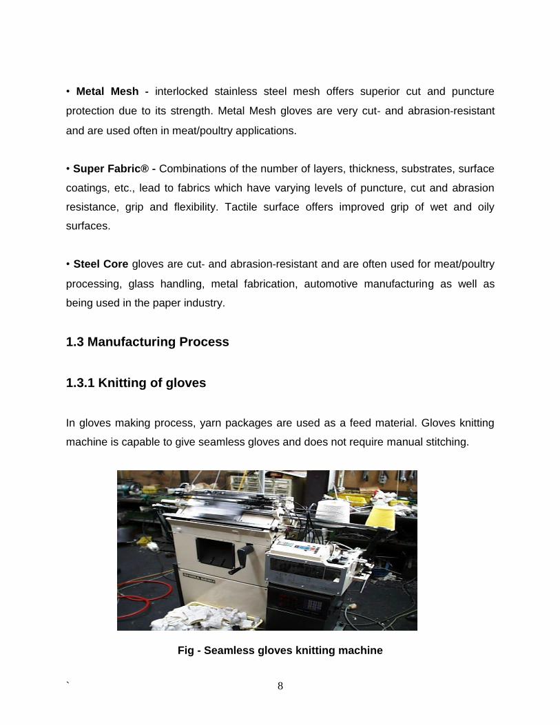
In gloves making process, yarn packages are used as a feed material. Gloves knitting
machine is capable to give seamless gloves and does not require manual stitching.
Fig - Seamless gloves knitting machine
` 9
The five finger gloves, with the fingers placed horizontally, are usually produced on
specialized knitting machines, equipped with special devices, for producing parts as
automatic beginning of the tubular finger, connection between fingers, in order to avoid
holes, insertion of an elastic yarn in border structure, patterning the gloves palm, with
jacquard pattern i.e., narrowing edges of the tubular palm fabric. Knitting routines for
manufacturing knitted glove are explained briefly in forthcoming paragraphs.
The knitting action starts with a piece of fabric which holds the knit during finger
production. Knitting action for different parts of gloves is carried out in the order 1-2-3-4-
5-6-7-8. During its production, the take down is executed by the auxiliary take down,
placed under the needle bed while the main take down is deactivated.
Fingers no 1 to 4 are knitted in a tubular style, knitted one after the other, on the same
number of needles but with different lengths. After the index finger production, the
connection between the fingers must be executed, in order to avoid the holes. The
connection between fingers it is made by cross linking of the loops from each finger
edges. Considering that the finger knitting is done on all needles, there are not any free
needles at the edges in order to receive a transferred loop. After connecting the finger,
palm and thumb finger will be knitted. The connection between thumb finger and palm
by knitting a tubular row with split transfer comes next.
The second part of the palm must be fashioned in both edges, by successive narrowing
of the tubular knitted fabric. The narrowing takes place by transferring inside the knitted
fabric some loops from the two needle beds. In order to get a designed form of the
narrowed fabric, some elements should be considered, i.e., the number of the rows
between the two narrowing actions, the number of needle steps toward the inside of the
fabric at transfer and the number of transferred stitches.
This knitting method permits full automatic knitting of gloves without requiring manual
stitching or drawing-in of the leading end of the yarn.
` 10
Patterning is also possible on the knitted gloves according to the designer’s creativity
and machine specifications.
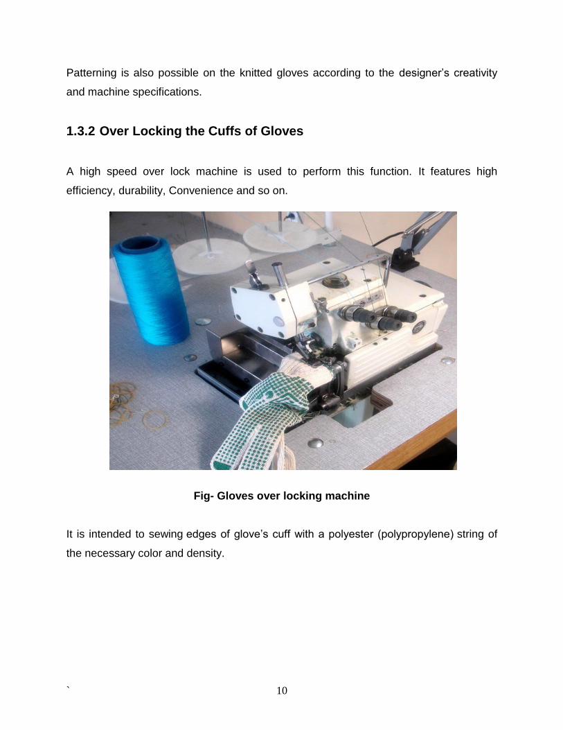
1.3.2 Over Locking the Cuffs of Gloves
A high speed over lock machine is used to perform this function. It features high
efficiency, durability, Convenience and so on.
Fig- Gloves over locking machine
It is intended to sewing edges of glove’s cuff with a polyester (polypropylene) string of
the necessary color and density.
` 11
1.3.3. Packing of Gloves
Packing of gloves is done by the electronic packing machine. This equipment opens
when ready for inputting the gloves, and it is on its level when ready for one dozen
packing. The electronic system controls the whole process. This machine is essential
equipment for every glove producer.
1.4 Performance of gloves
Glove performance and pass/fail criteria are included for the following hazardous
exposures:
• Mechanical protection – cut resistance, puncture resistance, abrasion resistance
• Chemical protection – chemical permeation resistance and chemical degradation
resistance
• Detection of holes
• Heat and flame protection – ignition resistance and burning behavior, heat degradation
resistance, conductive heat resistance
• Dexterity
The new standard also includes a recommended hand protection selection procedure,
and reference information on special considerations such as biological protection,
extreme temperature applications, clean room applications, hazardous materials
response applications, electrical protection and radiation hazards. A section on human
factors describes how fit, function and comfort are incorporated into selection.
At some point in the glove selection process, users may be faced with a decision among
different glove materials. When it comes to glove materials, some users may be
sensitive to the proteins found in latex – an issue that has prompted the glove industry
to find alternatives in materials such as vinyl nitrile and neoprene. Occasionally, users
may experience glove‐associated irritation that has nothing to do with an allergic
reaction. Suggested tips for alleviating such symptoms include:
` 12
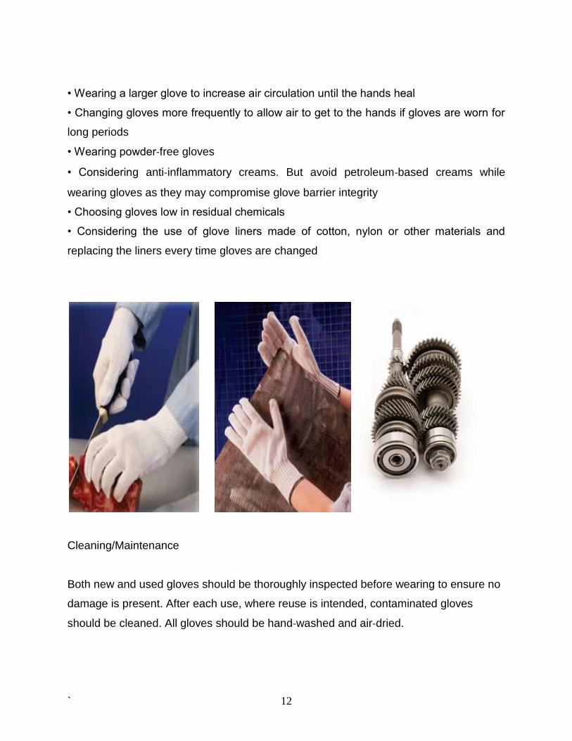
• Wearing a larger glove to increase air circulation until the hands heal
• Changing gloves more frequently to allow air to get to the hands if gloves are worn for
long periods
• Wearing powder‐free gloves
• Considering anti‐inflammatory creams. But avoid petroleum‐based creams while
wearing gloves as they may compromise glove barrier integrity
• Choosing gloves low in residual chemicals
• Considering the use of glove liners made of cotton, nylon or other materials and
replacing the liners every time gloves are changed
Cleaning/Maintenance
Both new and used gloves should be thoroughly inspected before wearing to ensure no
damage is present. After each use, where reuse is intended, contaminated gloves
should be cleaned. All gloves should be hand‐washed and air‐dried.
` 13
1.5 Mechanical properties of stainless steels
The mechanical properties of stainless steels are almost always requirements of the
product specifications used to purchase the product. For flat rolled products the
properties usually specified are tensile strength, yield stress (or proof stress), elongation
and Brinell or Rockwell hardness. Bar, tube, pipe, fittings etc. also usually require at
least tensile strength and yield stress. These properties give a guarantee that the
material in question has been correctly produced, and are also used by engineers to
calculate the working loads or pressures that the product can safely carry in service.
Typical Properties
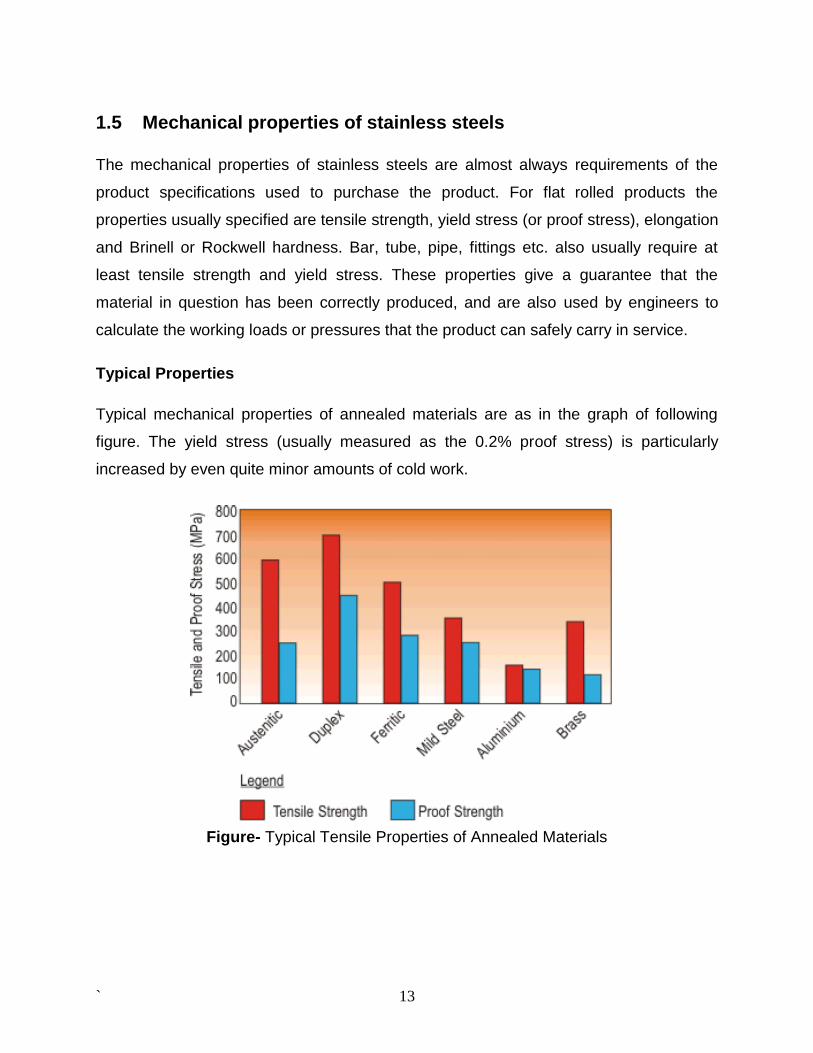
Typical mechanical properties of annealed materials are as in the graph of following
figure. The yield stress (usually measured as the 0.2% proof stress) is particularly
increased by even quite minor amounts of cold work.
Figure- Typical Tensile Properties of Annealed Materials
` 14
Yield Strength
An unusual feature of annealed austenitic stainless steels is that the yield strength is a
very low proportion of the tensile strength, typically only 40-45%. The comparable figure
for mild steel is about 65-70%. As engineering design calculations are frequently made
on yield criterion the low yield strength of austenitic stainless steels may well mean that
their design load cannot be higher than that of mild steel, despite the tensile strength
being substantially higher.
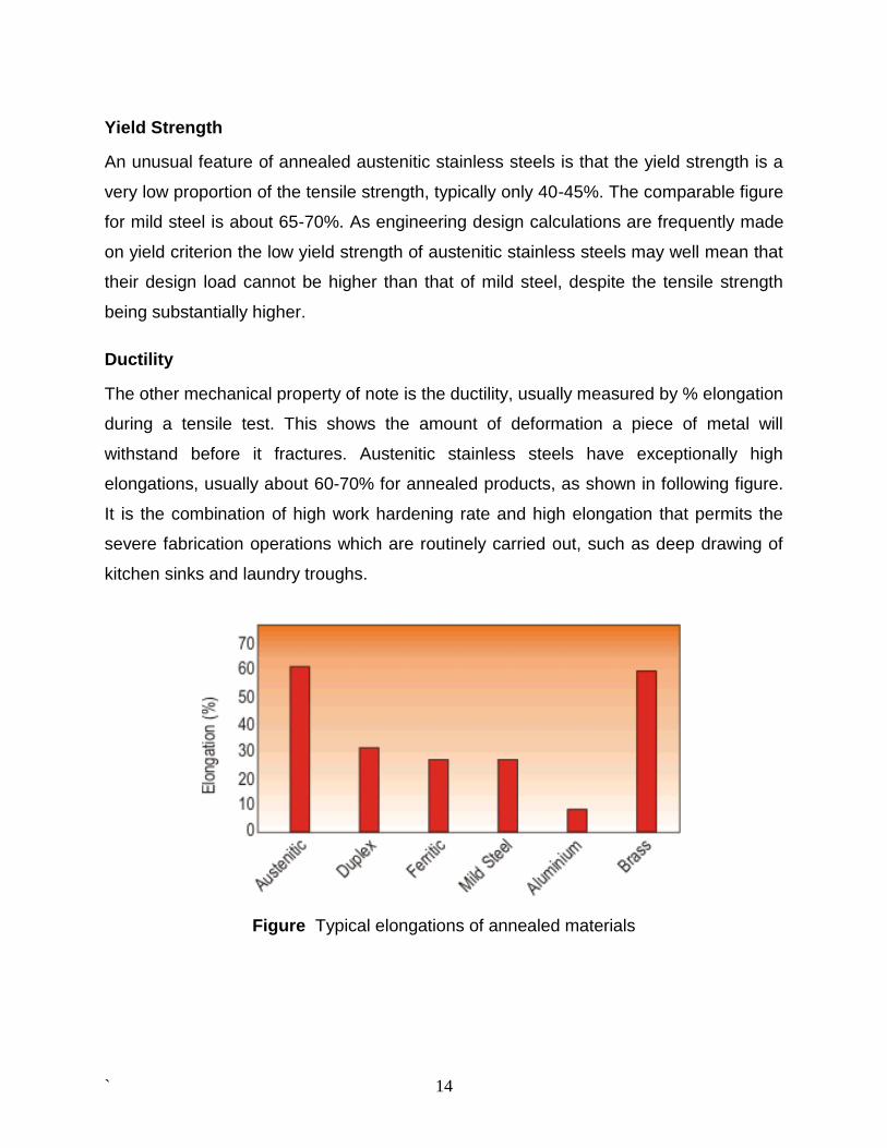
Ductility
The other mechanical property of note is the ductility, usually measured by % elongation
during a tensile test. This shows the amount of deformation a piece of metal will
withstand before it fractures. Austenitic stainless steels have exceptionally high
elongations, usually about 60-70% for annealed products, as shown in following figure.
It is the combination of high work hardening rate and high elongation that permits the
severe fabrication operations which are routinely carried out, such as deep drawing of
kitchen sinks and laundry troughs.
Figure Typical elongations of annealed materials
` 15
Hardness
Hardness (measured by Brinell, Rockwell or Vickers machines) is another value for the
strength of a material. Hardness is usually defined as resistance to penetration, so
these test machines measure the depth to which a very hard indenter is forced into a
material under the action of a known force. Each machine has a different shaped
indenter and a different force application system, so conversion between hardness
scales is not generally very accurate. Although conversion tables have been produced
these conversions are only approximate, and should not be used to determine
conformance to standards.
It is also sometimes convenient to do a hardness test and then convert the result to
tensile strength. Although the conversions for carbon and low alloy steels are fairly
reliable, those for stainless steels are much less so.
Mechanical Properties of Wire
The mechanical properties of the majority of the stainless steel wire products are
generally sufficiently described by the tensile strength. These products require
mechanical properties which are carefully chosen to enable the product to be fabricated
into the finished component and also to withstand the loads which will be applied during
service. Spring wire has the highest tensile strength of the wire generally manufactured;
it must be suitable for coiling into tension or compression springs without breaking
during forming. However, such high tensile strengths would be completely unsuitable for
forming or weaving applications because the wire would break on forming. Weaving
wires are supplied in a variety of tensile strengths carefully chosen so that the finished
woven screen will have adequate strength to withstand the service loads, and yet soft
enough to be crimped and to be formed into the screen satisfactorily. Mechanical
properties of wire for fasteners are another example where a careful balance in
mechanical properties is required. In this type of product the wire must be ductile
enough to form a quite complex head but the wire must be hard enough so that the
threads will not deform when the screw or bolt is assembled into the component. Good
examples are roofing bolts, wood screws and self-tapping screws; to achieve the
mechanical properties required for such components requires careful consideration of
` 16
the composition of the steel so that the work hardening rate will be sufficiently high to
form hard threads on thread rolling and yet not so high as to prevent the head from
being formed.
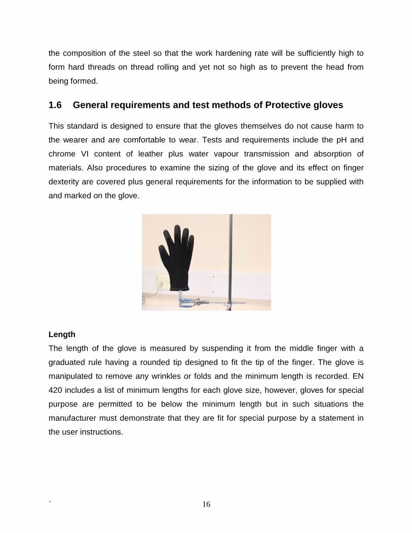
1.6 General requirements and test methods of Protective gloves This standard is designed to ensure that the gloves themselves do not cause harm to
the wearer and are comfortable to wear. Tests and requirements include the pH and
chrome VI content of leather plus water vapour transmission and absorption of
materials. Also procedures to examine the sizing of the glove and its effect on finger
dexterity are covered plus general requirements for the information to be supplied with
and marked on the glove.
Length
The length of the glove is measured by suspending it from the middle finger with a
graduated rule having a rounded tip designed to fit the tip of the finger. The glove is
manipulated to remove any wrinkles or folds and the minimum length is recorded. EN
420 includes a list of minimum lengths for each glove size, however, gloves for special
purpose are permitted to be below the minimum length but in such situations the
manufacturer must demonstrate that they are fit for special purpose by a statement in
the user instructions.
` 17
Sizing / Dexterity
Gloves are fitted on a hand of the size that they are intended to fit and comments are
made regarding comfort and fit. The wearer will then try to pick up pins of varying size to
provide an indication of dexterity. Five pins are defined of diameter from 5 mm to 11mm,
clearly the smaller the diameter that can be picked up the greater the dexterity result.
pH Value
The determination of pH value of both leathers and textiles on a glove is required. This
pH value shall be greater than 3.5 and less than 9.5. The test samples are taken from
the palm of the glove, if other part of the glove contains different material, these
materials shall be tested separately. A prepared test sample is extracted in water by
mechanical shaking; the aqueous extract is then decanted and the pH value determined
by a pH meter. An excessive amount of acid or alkali in a material has been linked to
skin dermatitis and may indicate poor process control.
BS EN 388: 2003 Protective gloves against mechanical risks.
This is the most common European Standard for testing gloves to be used in general
industrial applications. It is also referred to in many of the specialist glove standards, for
activities such as welding and handling of chemicals. EN 388 was first published in
1994 and subsequently revised in 2003. It includes four main physical tests to assess
the resistance of the gloves palm area to mild abrasion, cutting, tearing and puncture.
The performance of the glove is graded in accordance with four or five performance
levels. The end user is then able to select a glove with a performance level profile that
suits a particular work activity. So for example, a glove could be performance level 4 for
abrasion but level 1 for tearing (in European standards the higher the number, the
greater the protection).
Abrasion
Samples are cut from the palm of a glove and rubbed against a 100 grit abrasive paper
using a “Martindale” type abrasion machine. The number of cycles for the samples to
` 18
hole is measured. Four performance levels are defined in EN 388 ranging from level 1 =
holing > 100 cycles to Level 4 = holing > 8000 cycles.
Blade Cut
Samples are taken from the palm of a glove and the number of cycles to cut through the
full thickness of the test sample by a circular rotating blade is recorded. Blade
sharpness will vary and is assessed by using the cut test machine to cut through a
standard reference fabric. The cut resistance of the glove is based on a relative index
that compares the number of cycles to cut through the glove when compared with the
standard fabric. Five performance levels are defined in EN 388 ranging from level 1 =
Cut index > 1.2 to Level 5 = Cut index > 20.
Tear
“Trouser leg” type samples are taken from the palm of a glove and are torn apart using
a standard tensile test machine. Four performance levels are defined in EN 388 ranging
from level 1 = tear strength > 10 N to Level 4 = tear strength > 75 N.
Puncture
Samples are taken from the palm of a glove and the force required to penetrate the
sample with a defined stylus using a tensile test machine is measured. Four
performance levels are defined in EN 388 ranging from level 1 = Puncture force > 20 N
to Level 4 = Puncture force > 150 N.
2. Materials and Methods 2.1 Materials The stainless steel mono filament yarn of 60 micron diameter has been procured from
NIMROD INTERNATIONAL New Delhi, who is the sole supplier of the above filament in
India.
` 19
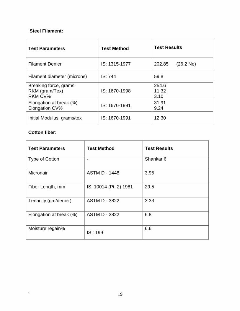
Steel Filament:
Test Parameters Test Method
Test Results
Filament Denier IS: 1315-1977 202.85 (26.2 Ne)
Filament diameter (microns) IS: 744 59.8
Breaking force, grams RKM (gram/Tex) RKM CV%
IS: 1670-1998 254.6 11.32 3.10
Elongation at break (%) Elongation CV%
IS: 1670-1991 31.91 9.24
Initial Modulus, grams/tex IS: 1670-1991 12.30
Cotton fiber:
Test Parameters Test Method Test Results
Type of Cotton - Shankar 6
Micronair ASTM D - 1448 3.95
Fiber Length, mm IS: 10014 (Pt. 2) 1981 29.5
Tenacity (gm/denier) ASTM D - 3822 3.33
Elongation at break (%) ASTM D - 3822 6.8
Moisture regain% IS : 199
6.6
` 20
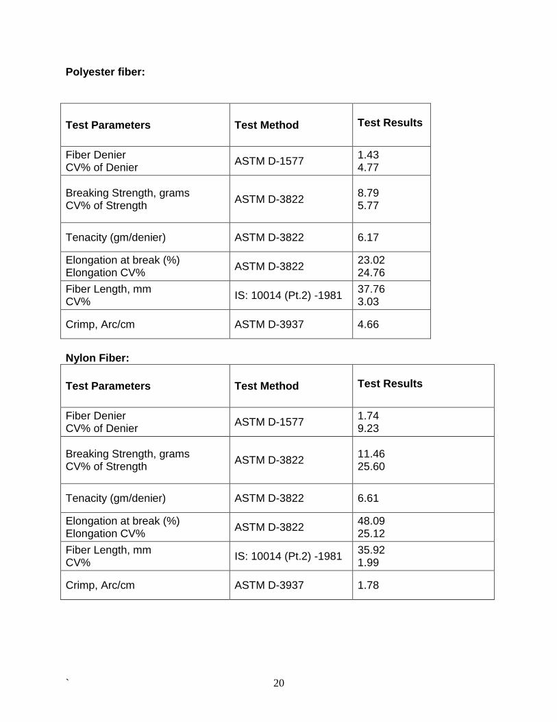
Polyester fiber:
Test Parameters Test Method
Test Results
Fiber Denier CV% of Denier
ASTM D-1577 1.43 4.77
Breaking Strength, grams CV% of Strength
ASTM D-3822 8.79 5.77
Tenacity (gm/denier) ASTM D-3822 6.17
Elongation at break (%) Elongation CV%
ASTM D-3822 23.02 24.76
Fiber Length, mm CV%
IS: 10014 (Pt.2) -1981 37.76 3.03
Crimp, Arc/cm ASTM D-3937 4.66
Nylon Fiber:
Test Parameters Test Method
Test Results
Fiber Denier CV% of Denier
ASTM D-1577 1.74 9.23
Breaking Strength, grams CV% of Strength
ASTM D-3822 11.46 25.60
Tenacity (gm/denier) ASTM D-3822 6.61
Elongation at break (%) Elongation CV%
ASTM D-3822 48.09 25.12
Fiber Length, mm CV%
IS: 10014 (Pt.2) -1981 35.92 1.99
Crimp, Arc/cm ASTM D-3937 1.78

` 21
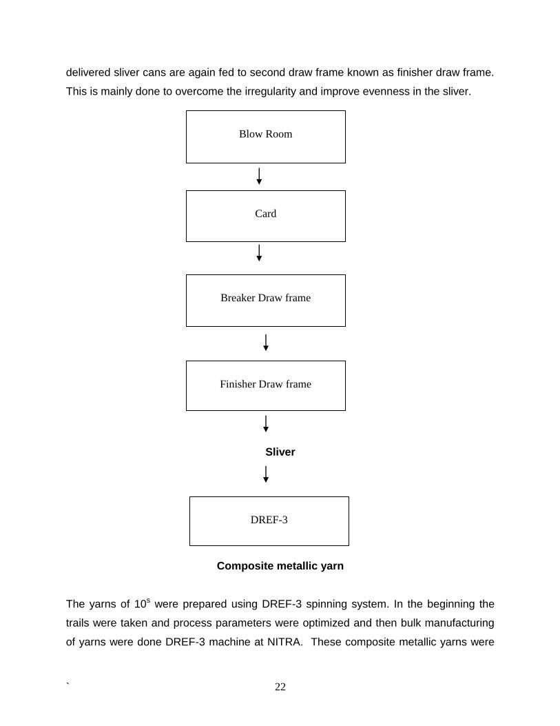
2.2 Methods The preparatory process to develop slivers of nylon, polyester and cotton fibers (to be
used as sheath for making composite metallic yarns at DREF-3 machine) is described
here as under.
Blow Room:- The main purpose of blow-room is opening and cleaning of the material being used. The
material is passed through various machines in order to achieve proper opening and
cleaning. In Blow-room, machines are selected as per the beating points required to
process nylon, polyester and cotton fibers.
Card:- Carding is the heart of the entire spinning process and as such requires utmost care.
‘To card well is to spin well’ is a very widely used term by all those concerned with
spinning technology. There have been remarkable changes in other areas of spinning,
but so far as carding is concerned basic operation of the machine remained almost
unchanged. The different speeds and settings are used to process nylon, polyester and
cotton fibers and are summarized in process parameters
Breaker Draw frame:- Draw frame is the process next to card. The main task of the draw frame is doubling
and drafting. Doubling is done to improve evenness of the sliver.
Drafting is done to make the fibers parallel to each other. To obtain an optimal value for
strength in the yarn characteristics, the fibers must be arranged parallel in the fiber
strand.
Finisher Draw frame:- The first passage in the draw frame is generally followed by a second passage. In the
first passage, many slivers are fed together and at exit only one sliver is formed. The
` 22
delivered sliver cans are again fed to second draw frame known as finisher draw frame.
This is mainly done to overcome the irregularity and improve evenness in the sliver.
Sliver
Composite metallic yarn The yarns of 10s were prepared using DREF-3 spinning system. In the beginning the
trails were taken and process parameters were optimized and then bulk manufacturing
of yarns were done DREF-3 machine at NITRA. These composite metallic yarns were
Blow Room
Card
Breaker Draw frame
Finisher Draw frame
DREF-3
` 23
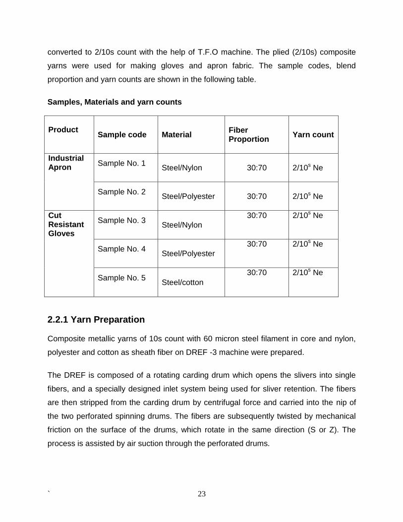
converted to 2/10s count with the help of T.F.O machine. The plied (2/10s) composite
yarns were used for making gloves and apron fabric. The sample codes, blend
proportion and yarn counts are shown in the following table.
Samples, Materials and yarn counts
Product
Sample code Material Fiber Proportion
Yarn count
Industrial Apron
Sample No. 1
Steel/Nylon 30:70 2/10s Ne
Sample No. 2
Steel/Polyester 30:70 2/10s Ne
Cut Resistant Gloves
Sample No. 3
Steel/Nylon
30:70 2/10s Ne
Sample No. 4
Steel/Polyester
30:70 2/10s Ne
Sample No. 5
Steel/cotton
30:70 2/10s Ne
2.2.1 Yarn Preparation
Composite metallic yarns of 10s count with 60 micron steel filament in core and nylon,
polyester and cotton as sheath fiber on DREF -3 machine were prepared.
The DREF is composed of a rotating carding drum which opens the slivers into single
fibers, and a specially designed inlet system being used for sliver retention. The fibers
are then stripped from the carding drum by centrifugal force and carried into the nip of
the two perforated spinning drums. The fibers are subsequently twisted by mechanical
friction on the surface of the drums, which rotate in the same direction (S or Z). The
process is assisted by air suction through the perforated drums.
` 24
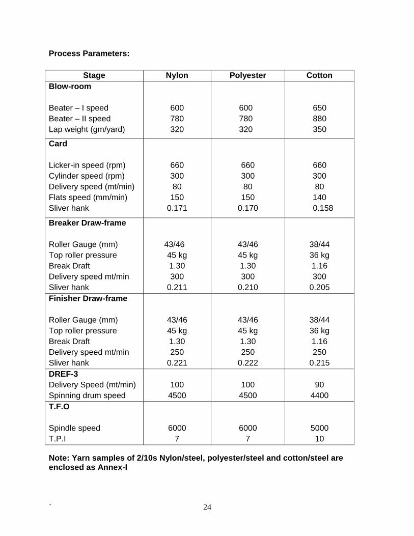
Process Parameters:
Stage Nylon Polyester Cotton
Blow-room
Beater – I speed
Beater – II speed
Lap weight (gm/yard)
600
780
320
600
780
320
650
880
350
Card
Licker-in speed (rpm)
Cylinder speed (rpm)
Delivery speed (mt/min)
Flats speed (mm/min)
Sliver hank
660
300
80
150
0.171
660
300
80
150
0.170
660
300
80
140
0.158
Breaker Draw-frame
Roller Gauge (mm)
Top roller pressure
Break Draft
Delivery speed mt/min
Sliver hank
43/46
45 kg
1.30
300
0.211
43/46
45 kg
1.30
300
0.210
38/44
36 kg
1.16
300
0.205
Finisher Draw-frame
Roller Gauge (mm)
Top roller pressure
Break Draft
Delivery speed mt/min
Sliver hank
43/46
45 kg
1.30
250
0.221
43/46
45 kg
1.30
250
0.222
38/44
36 kg
1.16
250
0.215
DREF-3
Delivery Speed (mt/min)
Spinning drum speed
100
4500
100
4500
90
4400
T.F.O
Spindle speed
T.P.I
6000
7
6000
7
5000
10
Note: Yarn samples of 2/10s Nylon/steel, polyester/steel and cotton/steel are enclosed as Annex-I
` 25
2.2.2 Selection of Glove knitting machine
A good quality glove knitting machine was required for the development of cut resistant
protective textiles using composite metallic yarn.
Trials have been taken on Chinese as well as Japanese glove knitting machines using composite
metallic yarn and found that Japanese machine produced better quality of gloves. The extensive
market survey also reveals that Japanese machines are better in technology & durability, offer
higher productivity & good product quality as compare to Chinese and other brand machines.
The Shima Seiki, Japan developed the world’s first automated glove knitting machine and since
then it has been the forerunner of the glove knitting technology. The Shima Seiki machines are
not only better in quality and consistency of knitting, but also metallurgy wise far superior than
any other brands. That is the reason why the manufacturers who are making gloves with
specialized cut resistant yarn, opt for Shima Sheiki machines only, because while running such
specialized yarn, the yarn does not break, but wearing of the machine parts is more than the
machine running with normal yarn. The 7G & 5G SFG machines are suitable for running
specialized yarns. Therefore Shima Seiki SFG 7G L/M automatic glove knitting machine has
been procured for glove making in this project.
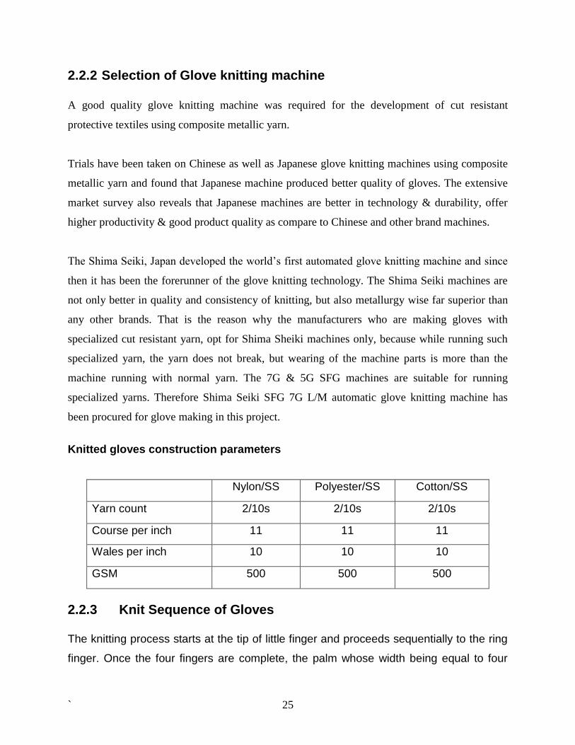
Knitted gloves construction parameters
Nylon/SS Polyester/SS Cotton/SS
Yarn count 2/10s 2/10s 2/10s
Course per inch 11 11 11
Wales per inch 10 10 10
GSM 500 500 500
2.2.3 Knit Sequence of Gloves The knitting process starts at the tip of little finger and proceeds sequentially to the ring
finger. Once the four fingers are complete, the palm whose width being equal to four
` 26
fingers is knit. This portion is called the 4-finger palm. Knitting of the thumb starts at its
tip. Once the thumb is complete, the palm whose width being equal to the five fingers is
knit. This portion is called the 5-finger palm. The rib whose width being same as the 5-
finger palm is knit. Finally, the X knit part is formed. This part is again as wide as the 5-
finger palm.
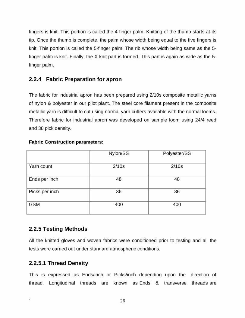
2.2.4 Fabric Preparation for apron
The fabric for industrial apron has been prepared using 2/10s composite metallic yarns
of nylon & polyester in our pilot plant. The steel core filament present in the composite
metallic yarn is difficult to cut using normal yarn cutters available with the normal looms.
Therefore fabric for industrial apron was developed on sample loom using 24/4 reed
and 38 pick density.
Fabric Construction parameters:
Nylon/SS Polyester/SS
Yarn count 2/10s 2/10s
Ends per inch 48 48
Picks per inch 36 36
GSM 400 400
2.2.5 Testing Methods
All the knitted gloves and woven fabrics were conditioned prior to testing and all the
tests were carried out under standard atmospheric conditions.
2.2.5.1 Thread Density
This is expressed as Ends/inch or Picks/inch depending upon the direction of
thread. Longitudinal threads are known as Ends & transverse threads are
` 27
known as Picks. These are counted with the help of magnification glass with
ruler known as Pick Counter.
2.2.5.2 Count of Threads
Count of threads in a fabric can be determined by taking out 25-50 threads
from a piece of 50cm x 50cm. These threads are weighted accurately on
electronic balance and their length is determined after correcting the crimp and
then the count is calculated. Thread density and count of threads affect the
construction of the fabric & all other properties.
2.2.5.3 Weight of Fabric (GSM)
Weight of fabric is determined by weighing a fabric of any area say 25cm x 25cm
& is generally expressed in terms of GSM (gram per square meter). Now a
day’s round cutters are also available to cut fabric of known area say 100 sq.
cm.
2.2.5.4 Tensile Strength
Tensile strength is an important parameter as it is crucial for the life of the
fabric. The breaking strength of a fabric refers to its resistance to tensile force
and used for quality control as well as performance test. The tensile strength of
a fabric should always be several times greater than the maximum stress
likely to be encountered in use, because during the life cycle of most textile
articles, strength of the fabric diminishes by the rubbing and chemical action.
Tensile strength of fabric is determined on the Tensile strength tester.
Normally 4-5 strips in warp and weft wise direction are taken from the sample in
such a way that most of the threads are covered. Then these strips are tested &
results are expressed as average value in kg or Newton.
` 28
Cut strip method: The strip of fabric is cut exactly 2.0 inch wide. The test length should
be 8 inch between the jaws so enough extra length must be allowed for gripping in the
jaws. The specimen will be mounted centrally, securely gripped along the full width to
prevent slipping and the jaws aligned and parallel so that the load is applied uniformly
across the full specimen width. This method is used only for coated or heavy sized
fabrics where reveling of threads is very difficult.
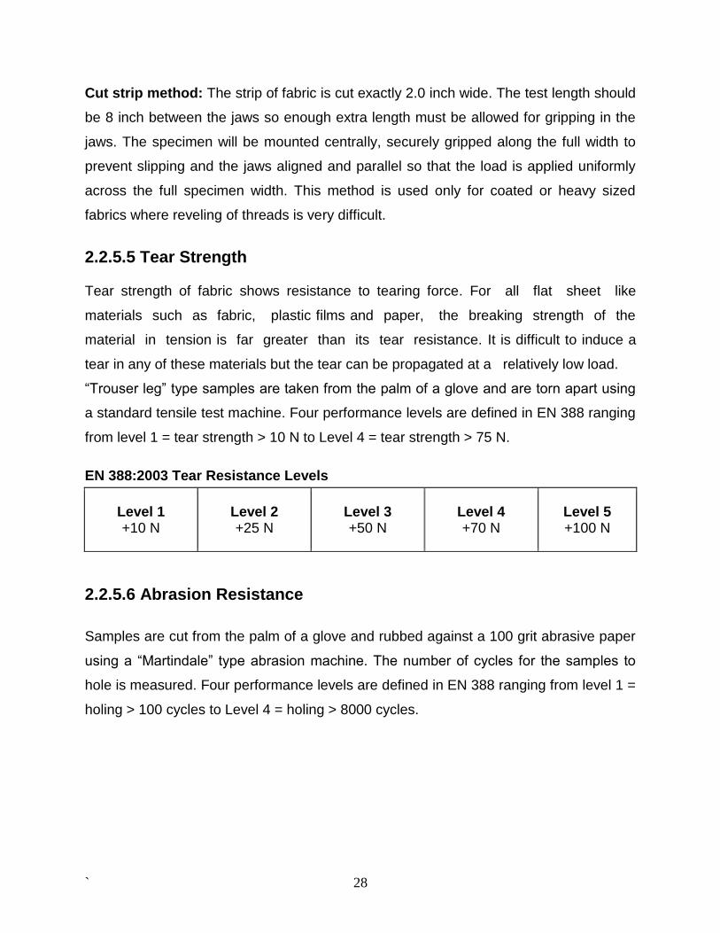
2.2.5.5 Tear Strength
Tear strength of fabric shows resistance to tearing force. For all flat sheet like
materials such as fabric, plastic films and paper, the breaking strength of the
material in tension is far greater than its tear resistance. It is difficult to induce a
tear in any of these materials but the tear can be propagated at a relatively low load.
“Trouser leg” type samples are taken from the palm of a glove and are torn apart using
a standard tensile test machine. Four performance levels are defined in EN 388 ranging
from level 1 = tear strength > 10 N to Level 4 = tear strength > 75 N.
EN 388:2003 Tear Resistance Levels
Level 1 +10 N
Level 2 +25 N
Level 3 +50 N
Level 4 +70 N
Level 5 +100 N
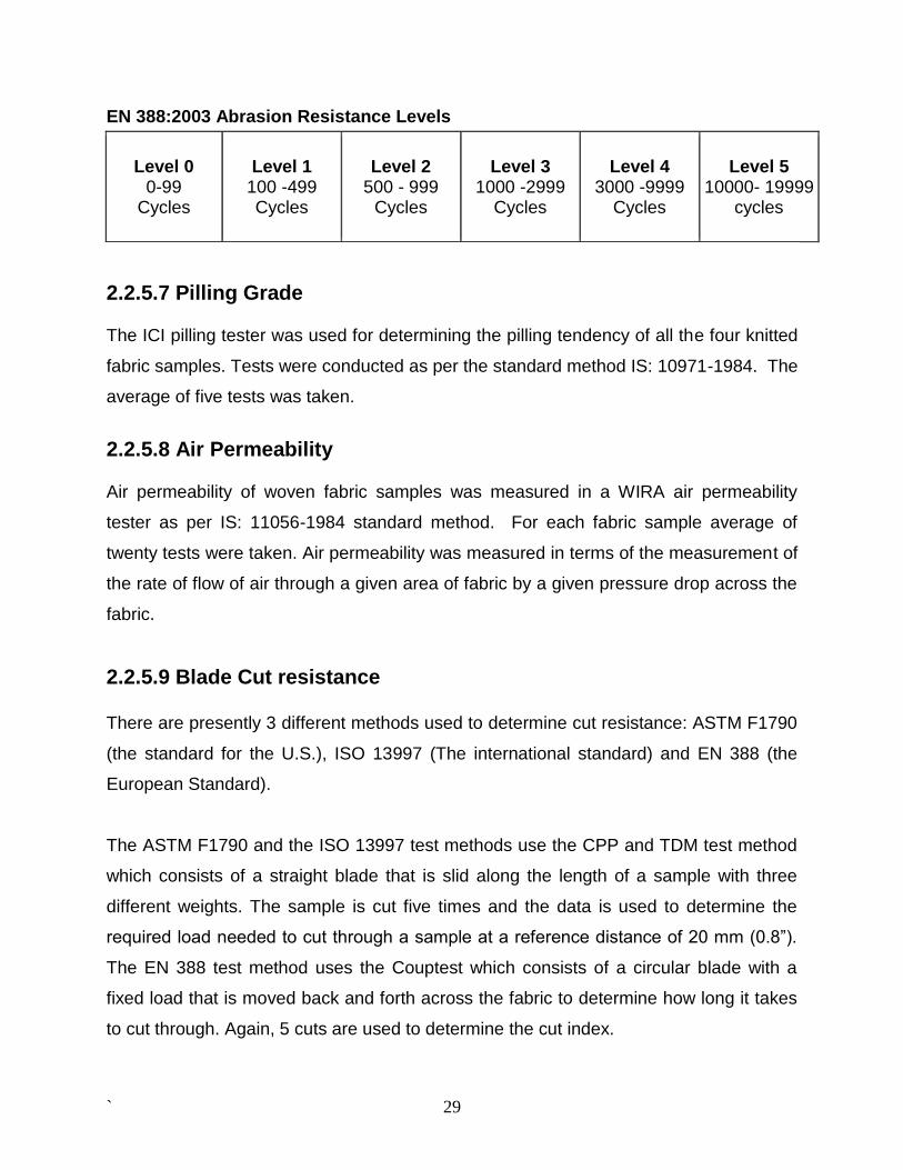
2.2.5.6 Abrasion Resistance
Samples are cut from the palm of a glove and rubbed against a 100 grit abrasive paper
using a “Martindale” type abrasion machine. The number of cycles for the samples to
hole is measured. Four performance levels are defined in EN 388 ranging from level 1 =
holing > 100 cycles to Level 4 = holing > 8000 cycles.
` 29
EN 388:2003 Abrasion Resistance Levels
Level 0 0-99
Cycles
Level 1 100 -499 Cycles
Level 2 500 - 999
Cycles
Level 3 1000 -2999
Cycles
Level 4 3000 -9999
Cycles
Level 5
10000- 19999 cycles
2.2.5.7 Pilling Grade
The ICI pilling tester was used for determining the pilling tendency of all the four knitted
fabric samples. Tests were conducted as per the standard method IS: 10971-1984. The
average of five tests was taken.
2.2.5.8 Air Permeability
Air permeability of woven fabric samples was measured in a WIRA air permeability
tester as per IS: 11056-1984 standard method. For each fabric sample average of
twenty tests were taken. Air permeability was measured in terms of the measurement of
the rate of flow of air through a given area of fabric by a given pressure drop across the
fabric.
2.2.5.9 Blade Cut resistance There are presently 3 different methods used to determine cut resistance: ASTM F1790
(the standard for the U.S.), ISO 13997 (The international standard) and EN 388 (the
European Standard).
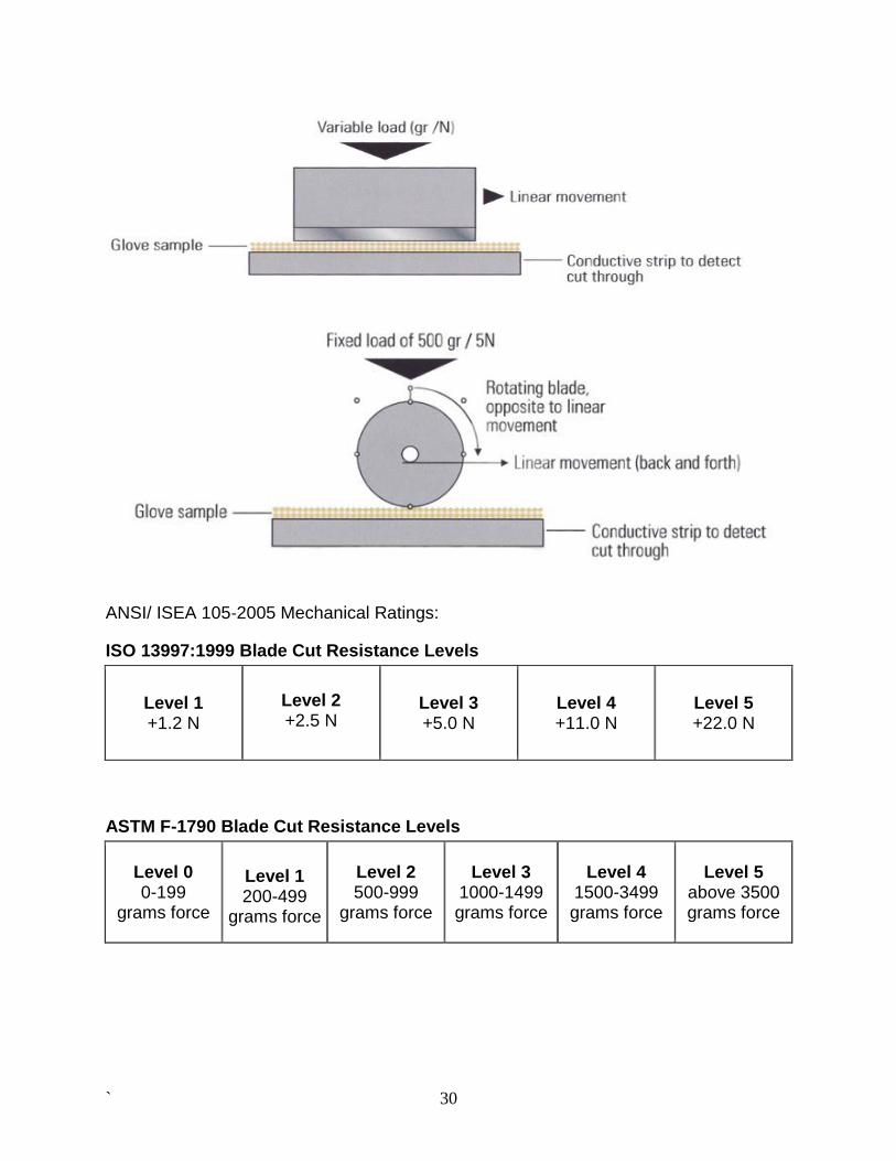
The ASTM F1790 and the ISO 13997 test methods use the CPP and TDM test method
which consists of a straight blade that is slid along the length of a sample with three
different weights. The sample is cut five times and the data is used to determine the
required load needed to cut through a sample at a reference distance of 20 mm (0.8”).
The EN 388 test method uses the Couptest which consists of a circular blade with a
fixed load that is moved back and forth across the fabric to determine how long it takes
to cut through. Again, 5 cuts are used to determine the cut index.
` 30
ANSI/ ISEA 105‐2005 Mechanical Ratings:
ISO 13997:1999 Blade Cut Resistance Levels
Level 1 +1.2 N
Level 2 +2.5 N
Level 3 +5.0 N
Level 4 +11.0 N
Level 5 +22.0 N
ASTM F-1790 Blade Cut Resistance Levels
Level 0 0-199
grams force
Level 1 200-499
grams force
Level 2 500-999
grams force
Level 3 1000-1499 grams force
Level 4 1500-3499 grams force
Level 5 above 3500 grams force
` 31
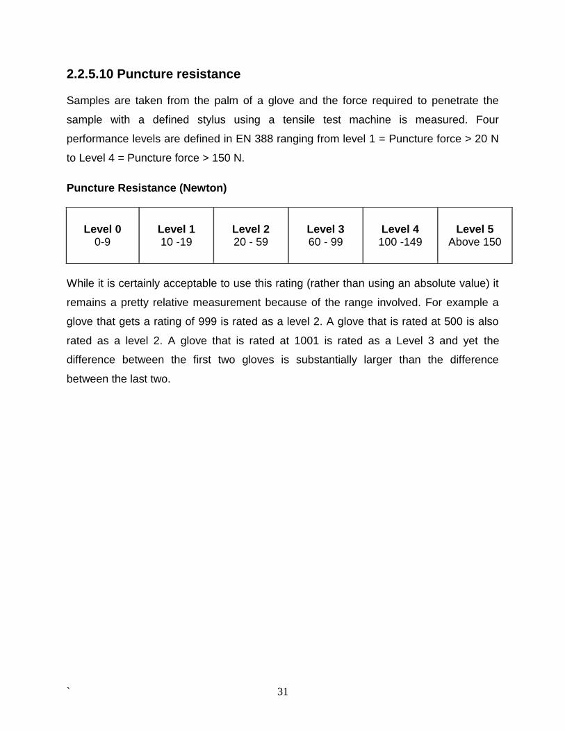
2.2.5.10 Puncture resistance
Samples are taken from the palm of a glove and the force required to penetrate the
sample with a defined stylus using a tensile test machine is measured. Four
performance levels are defined in EN 388 ranging from level 1 = Puncture force > 20 N
to Level 4 = Puncture force > 150 N.
Puncture Resistance (Newton)
Level 0
0-9
Level 1 10 -19
Level 2 20 - 59
Level 3 60 - 99
Level 4
100 -149
Level 5 Above 150
While it is certainly acceptable to use this rating (rather than using an absolute value) it
remains a pretty relative measurement because of the range involved. For example a
glove that gets a rating of 999 is rated as a level 2. A glove that is rated at 500 is also
rated as a level 2. A glove that is rated at 1001 is rated as a Level 3 and yet the
difference between the first two gloves is substantially larger than the difference
between the last two.