Embed Size (px)
Citation preview

M280 Reference Guide Revision D August 2013 2800513-1B

M280 Reference Guide
8-21-2013, Rev D. Page 1
1. Introduction …………………………………………………..... 2 2. Product Specifications ………………………….…………… 3 3. Unpacking M280 …………………………………….………… 4 4. Getting Started ………………………………..………………. 4 5. Using M280 ………………………………………..…………… 9
Copyright © 2013 E-Seek Incorporated. All Rights Reserved. E-Seek reserves the right to make changes to any product to improve reliability, function or design. E-Seek does not assume any product liability arising out of, or in connection with, the application or use of the product, circuit or application described herein. No license is granted, either expressly or by implication, estoppel, or otherwise under any patent right or patent, covering or relating to any combination, system, apparatus, machine, material method, or process in which E-Seek products might be used. An implied license only exists for equipment, circuits and subsystems contained in E-Seek products. E-Seek and the E-Seek logo are registered trademarks of E-Seek Incorporated. Other product names mentioned in this Reference Guide may be trademarks or registered trademarks of their respective companies and are hereby acknowledged. For latest driver and manual you can visit: http://www.e-seek.com/product_m280.asp Website: www.e-seek.com Patented Product
Sales & Marketing 245 Fischer Ave #D5 Costa Mesa, CA 92626 Tel: (714) 545-3316 Fax: (714) 545-3595
R & D Center 9471 Ridgehaven Ct. #E San Diego, CA 92123 Tel: (858) 495-1900 Fax: (858) 495-1901
M280 Reference Guide
8-21-2013, Rev D. Page 2
1. Introduction The E-Seek M280 allows for the reading and capture of all electronic data while concurrently providing the ability to scan and capture a complete image of both sides of an ID Card or License. The M280 reads all data from both the 2 Dimensional Barcode (PDF 417) and the Magnetic Stripe utilized on ID cards and Drivers’ Licenses. In addition, the ID card or license can be positioned on the scratch proof glass lens of the M280, and with the simple press of a button a full high resolution image (JPEG) of the ID is captured and attached to the data stream. With the ability to quickly and easily marry the Electronic data to the Image, the Model 280 provides a capability that is being required by an increasing number of applications.
Ideal For:
M280 Major Components
Figure 1-1. Front View
• Police Patrols • Vote systems • Border control • Law Enforcement • Kiosks
• Visitor/Lobby management • Access control • Passenger check-in • Department of Motor Vehicles • Club/VIP/Royalty card
• Age Verification • ID Authentication • Casino/Gaming • Check Cashing • Credit card/POS terminal • Automatic Data Entry
LED’s Indicator Imager Window
Image capture Button
2D & Linear Barcode Reader
Magnetic Stripe Reader

M280 Reference Guide
8-21-2013, Rev D. Page 3
Figure 1-2. Back & Side View
2. Product Specifications
Imager CMOS Image Sensor (272 DPI)
Barcode Reader 2D: PDF417, Linear: CODE 39 & CODE 128
Magnetic Reader 3 Track Magnetic Reader(ANSI, ISO, CDL, AAMVA)
Card size ISO Standard Size 2.125" x 3.375"
Key Image Capture button
Weight 0.884 lb (401 grams)
Dimensions 7.11" Length x 4.53" Width x 2.80" Height
Operation Environment Operating Temperature: 32 to 114 F (0°C to 45°C) Operating Humidity: 10% to 90% (non-condensing)
Connectivity USB 2.0 High speed (Type B)
Power Supply USB Power
USB Port
M280 Reference Guide
8-21-2013, Rev D. Page 4
Recommended System Requirements
• More than Intel Core 2, or AMD Phenom™ CPU • More than 2 GB memory • USB2.0 High speed • Windows XP with Service Pack 2 or later, Windows Vista, or Windows 7 (32-bit or 64-bit)
3. Unpacking M280 The M280 package includes:
• M280 Device • USB Cable
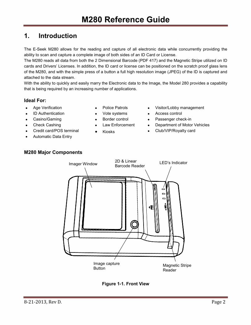
The M280 is provided with a USB interface cable. This cable allows the M280 to interface with standard USB port on your computer.
Figure 3-1. USB Cable
4. Getting Started
Install M280 on the PC Connect the M280 to the system using USB Cable
NOTE: M280 will automatically install on Windows 7 and Vista.
USB-B USB-A
M280 Reference Guide
8-21-2013, Rev D. Page 5
If your system is different than above, please do the following:
4.1 Download Device Driver from the following link: http://www.e-seek.com/product_m280.asp
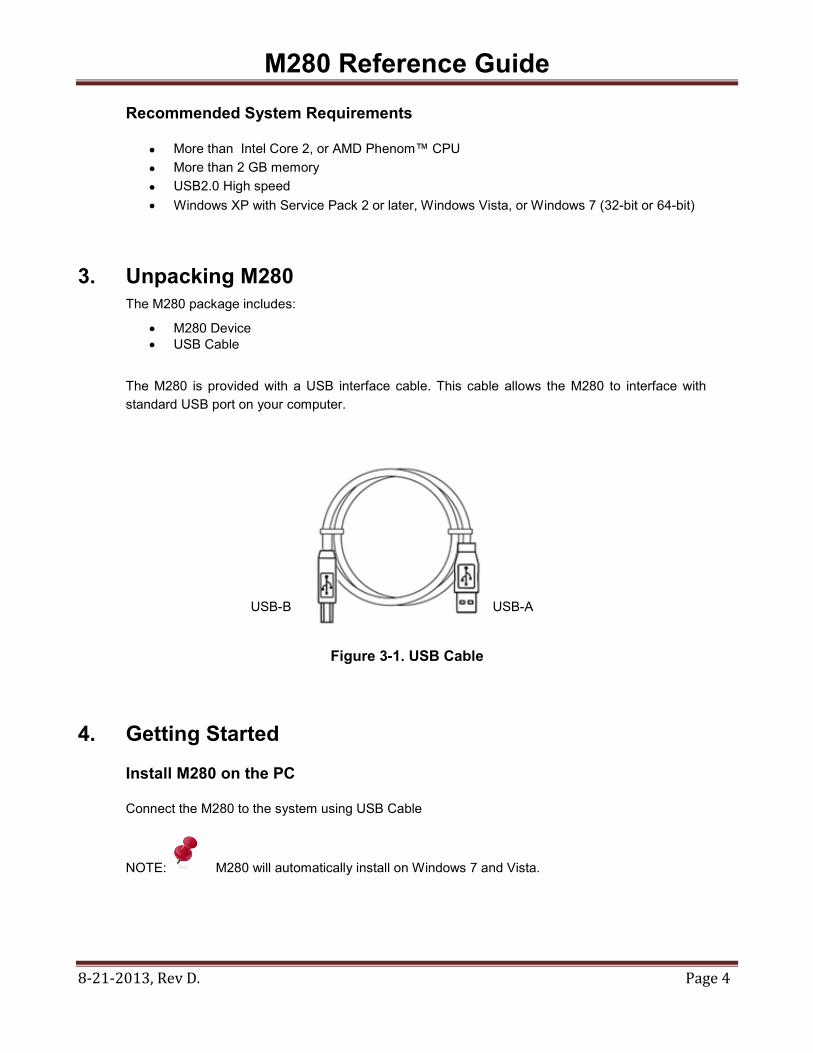
Save the zip file into your system and open it. You will see 3 different folders.
• W2K -> Windows 2000 - x86 : 32bit
• Wxp -> Window Xp
- x64 : 64bit - x86 : 32bit
• Wlh -> Vista , Window 7 and Windows 8
- x64 : 64bit - x86 : 32bit
Figure 4-1. Zip Files
NOTE: Remember where you saved the Zip file. You will need to
select it to install the driver.
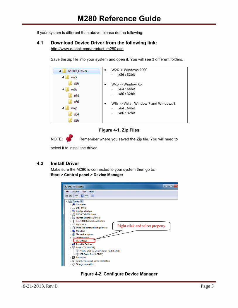
4.2 Install Driver Make sure the M280 is connected to your system then go to:
Start > Control panel > Device Manager
Figure 4-2. Configure Device Manager
Right click and select property

M280 Reference Guide
8-21-2013, Rev D. Page 6
Select Update Driver
Figure 4-3. Update Driver
Select “Browse My Computer for Driver Software”
Figure 4-4. Driver Software

M280 Reference Guide
8-21-2013, Rev D. Page 7
Select appropriate Device Driver from zip file downloaded from website.
Figure 4-5. Select Device Driver
Successfully updated M280 driver.
Figure 4-6. Driver Updated

M280 Reference Guide
8-21-2013, Rev D. Page 8
4.3 Check for Proper Installation
Go to: Start > Control panel > Device Manager. Select and open Universal Serial Bus Control, right click on M280 USB Driver and select properties. You will see “This device is working properly“.
Figure 4-7. Device Working Properly
Note: The Windows Vista and 7 are supported automatic driver installation.
M280 Reference Guide
8-21-2013, Rev D. Page 9
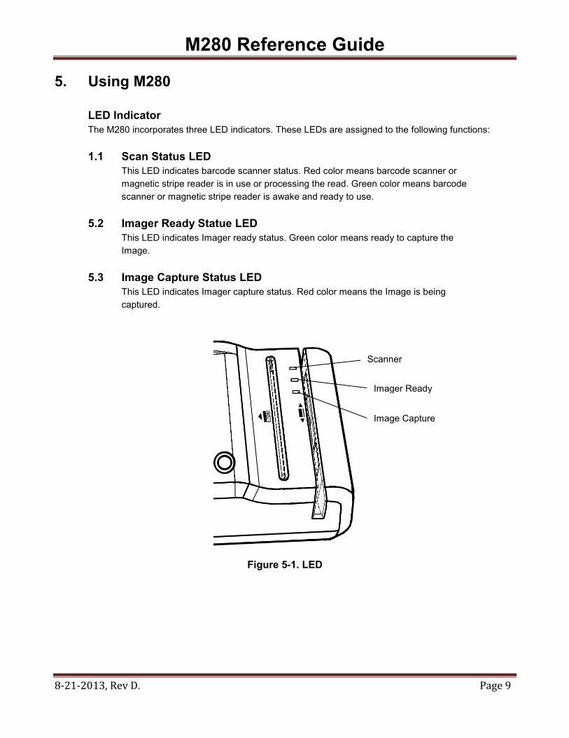
5. Using M280 LED Indicator
The M280 incorporates three LED indicators. These LEDs are assigned to the following functions:
1.1 Scan Status LED This LED indicates barcode scanner status. Red color means barcode scanner or magnetic stripe reader is in use or processing the read. Green color means barcode scanner or magnetic stripe reader is awake and ready to use.
5.2 Imager Ready Statue LED
This LED indicates Imager ready status. Green color means ready to capture the Image.
5.3 Image Capture Status LED
This LED indicates Imager capture status. Red color means the Image is being captured.
Figure 5-1. LED
Scanner
Imager Ready
Image Capture