Embed Size (px)
Citation preview
Journal of Clinical Neuroscience 18 (2011) 741–749
Contents lists available at ScienceDirect
Journal of Clinical Neuroscience
journal homepage: www.elsevier .com/ locate/ jocn
Review
Technique, challenges and indications for percutaneous pedicle screw fixation
Ralph J. Mobbs a,⇑, Praveenan Sivabalan b, Jane Li b
a Department of Neurosurgery, Prince of Wales Private Hospital, Suite 3, Level 7, Sydney Spine Clinic, Randwick, New South Wales 2031, Australiab Clinical School, Faculty of Medicine, University of New South Wales, Sydney, New South Wales, Australia
a r t i c l e i n f o
Article history:Received 2 July 2010Accepted 22 September 2010
Keywords:Minimally invasive surgeryMISPercutaneous pedicle fixationSpinal fusion
0967-5868/$ - see front matter Crown Copyright � 2doi:10.1016/j.jocn.2010.09.019
⇑ Corresponding author. Tel.: +61 2 9650 4766.E-mail address: [email protected] (R.J. Mo
a b s t r a c t
Minimally invasive techniques in spinal surgery are increasing in popularity due to numerous potentialadvantages, including reduced length of stay, blood loss and requirements for post-operative analgesia aswell as earlier return to work. This review discusses guidelines for safe implantation of percutaneouspedicle screws using an image intensifier technique. As indications for percutaneous pedicle screw tech-niques expand, the nuances of the minimally invasive surgery technique will also expand. It is paramountthat experienced surgeons share their collective knowledge to assist surgeons at their early attempts ofthese complex, and potentially dangerous, procedures. Technical challenges of percutaneous pediclescrew fixation techniques are also discussed including: small pedicle cannulation, percutaneous rodinsertion for multilevel constructs, incision selection for multilevel constructs, changing direction withpercutaneous pedicle screw placement, L5/S1 screw head proximity and sclerotic pedicles with difficultJamshidi placement. We discuss potential indications for minimally invasive fusion techniques for com-plex spinal surgery and support these with descriptions of illustrative patients.
Crown Copyright � 2010 Published by Elsevier Ltd. All rights reserved.
1. Introduction
Pedicle screw instrumentation enables a rigid construct to pro-mote stability and fusion for numerous spinal pathologies includ-ing: trauma, tumours, deformity and degenerative disease. Thesafety of traditional open techniques for pedicle screw placementhas been well documented; however, due to the advantages ofminimally invasive surgery (MIS), demand for percutaneous pedi-cle screw insertion will increase. Improvements in minimally inva-sive instrumentation have also broadened the scope of spinaldisorders that surgeons can operate on.1,2
Percutaneous pedicle screw insertion can be an intimidatingprospect for surgeons who have been trained in open techniquesonly. The initial change has a steep learning curve; however, thereare several basic principles that can assist the surgeon in safeplacement of the Jamshidi needle into a thoracic or lumbar pedicle.
2. Open versus minimally invasive surgery
Conventional open spine surgery has several reported limita-tions including extensive blood loss, post-operative muscle painand infection risk. The paraspinal muscle dissection involved inopen spine surgery (Fig. 1) can cause muscular denervation, in-creased intramuscular pressure, ischaemia, necrosis and revascu-
010 Published by Elsevier Ltd. All r
bbs).
larisation injury resulting in muscle atrophy and scarring, oftenassociated with prolonged post-operative pain and disability.Spinal fixation utilising muscle-dilating approaches (Figs. 1 and2) to minimise surgical incision length, surgical cavity size andthe amount of iatrogenic soft-tissue injury associated with surgicalspinal exposure, without compromising outcomes, is thus a desir-able advancement.3–12
No published articles of high-quality show that MIS is superiorto open spinal surgery; however, there is a trend towards MIS ofthe spine due to lower complication rates and approach-relatedmorbidity, with minimal soft tissue trauma, reduced intra-opera-tive blood loss/risk of transfusion, improved cosmesis, decreasedpost-operative pain and narcotic usage, shorter hospital stays withfaster return to work and thus reduced overall health carecosts.1,4,6–9,13,14 Despite this, some reports believe that minimalexposure is associated with incomplete treatment of pathology,13
due to significantly decreased visualisation with MIS.10 Anotherpotential limitation includes the use of imaging-guided pediclescrew placement. Imaging increases operating times and patient/surgeon exposure to ionising radiation. Non-radiological naviga-tion methods thus need to be explored to further improve MIS.3,10
The senior author (RJ Mobbs) has inserted more than 700 percu-taneous pedicle screws (Fig. 2) with two significantly misplacedscrews (0.29%), and one screw placement resulting in a permanentnerve root injury with a pedicle fracture (0.14%). Both complica-tions were within the initial 10 patients, representing a steeplearning curve with this technique.
ights reserved.
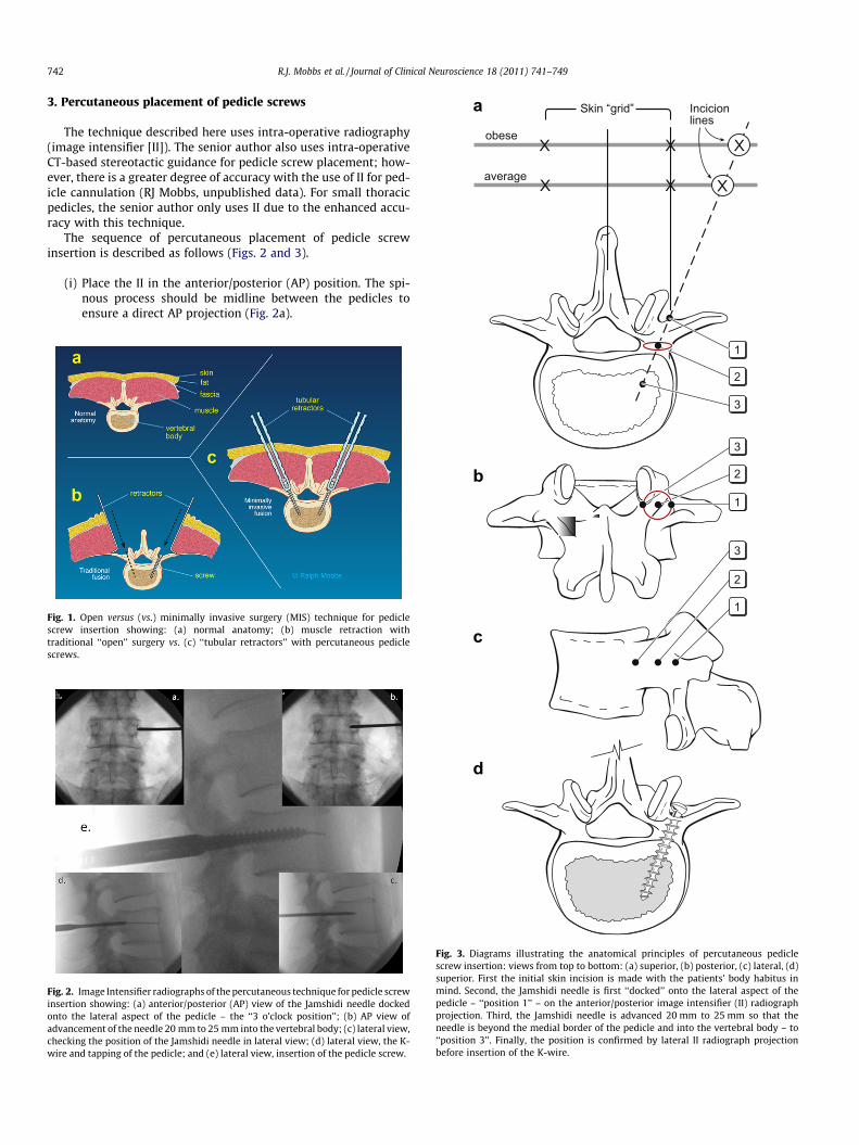
average
obese
Skin “grid” Incicionlines
a
742 R.J. Mobbs et al. / Journal of Clinical Neuroscience 18 (2011) 741–749
3. Percutaneous placement of pedicle screws
The technique described here uses intra-operative radiography(image intensifier [II]). The senior author also uses intra-operativeCT-based stereotactic guidance for pedicle screw placement; how-ever, there is a greater degree of accuracy with the use of II for ped-icle cannulation (RJ Mobbs, unpublished data). For small thoracicpedicles, the senior author only uses II due to the enhanced accu-racy with this technique.
The sequence of percutaneous placement of pedicle screwinsertion is described as follows (Figs. 2 and 3).
(i) Place the II in the anterior/posterior (AP) position. The spi-nous process should be midline between the pedicles toensure a direct AP projection (Fig. 2a).
Fig. 1. Open versus (vs.) minimally invasive surgery (MIS) technique for pediclescrew insertion showing: (a) normal anatomy; (b) muscle retraction withtraditional ‘‘open’’ surgery vs. (c) ‘‘tubular retractors’’ with percutaneous pediclescrews.
Fig. 2. Image Intensifier radiographs of the percutaneous technique for pedicle screwinsertion showing: (a) anterior/posterior (AP) view of the Jamshidi needle dockedonto the lateral aspect of the pedicle – the ‘‘3 o’clock position’’; (b) AP view ofadvancement of the needle 20 mm to 25 mm into the vertebral body; (c) lateral view,checking the position of the Jamshidi needle in lateral view; (d) lateral view, the K-wire and tapping of the pedicle; and (e) lateral view, insertion of the pedicle screw.
1
1
2
2
3
3
1
2
3
b
c
d
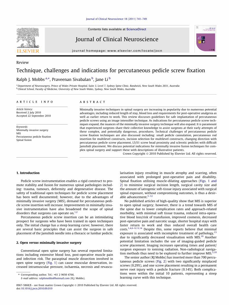
Fig. 3. Diagrams illustrating the anatomical principles of percutaneous pediclescrew insertion: views from top to bottom: (a) superior, (b) posterior, (c) lateral, (d)superior. First the initial skin incision is made with the patients’ body habitus inmind. Second, the Jamshidi needle is first ‘‘docked’’ onto the lateral aspect of thepedicle – ‘‘position 1’’ – on the anterior/posterior image intensifier (II) radiographprojection. Third, the Jamshidi needle is advanced 20 mm to 25 mm so that theneedle is beyond the medial border of the pedicle and into the vertebral body – to‘‘position 3’’. Finally, the position is confirmed by lateral II radiograph projectionbefore insertion of the K-wire.
R.J. Mobbs et al. / Journal of Clinical Neuroscience 18 (2011) 741–749 743
(ii) Mark the position of the lateral aspect of the pedicle on theskin. Depending upon the depth of the tissue between skinand pedicle, the skin incision should be made laterally(Fig. 3) so that the Jamshidi needle can be angled appropri-ately when inserting it into the pedicle.
(iii) Place the Jamshidi needle through the skin incision and‘‘dock’’ onto the lateral aspect of the pedicle (Fig. 2a). Thisis called the ‘‘3 o-clock’’ position.
(iv) Advance the Jamshidi needle 20 mm to 25 mm into the ped-icle, making sure the needle remains lateral to the medialpedicle wall (Figs. 2b and 3).
(v) Position the II in the lateral plane. The Jamshidi needleshould now be in the vertebral body, and therefore ‘‘safe’’with no risk of medial pedicle breach (Fig. 2c).
(vi) Place a K-wire down the Jamshidi needle and place a pedicletap down the trajectory of the K-wire (Fig. 2d).
(vii) Place the final pedicle screw with the screw placed down theK-wire (Fig. 2e), making sure not to advance the K-wirebeyond the anterior aspect of the vertebral body.
4. Challenges unique to MIS/percutaneous pedicle screwinsertion
There are many technical challenges unique to the percutane-ous pedicle screw insertion technique. After the surgeon is com-fortable with MIS techniques for single-level degenerativepathologies, the temptation is to attempt more difficult multi-levelconstructs such as those required in patients with tumour andtrauma pathologies.
The senior author has identified common challenges describedin the following sections.
4.1. Changing direction of screw placement following initial pediclecannulation
Following initial placement of the Jamshidi needle into the ver-tebral body, the lateral projection may demonstrate a poor trajec-tory that the surgeon may wish to correct. Using the pedicle tapplaced down the K-wire, the surgeon can ‘‘redirect’’ the tap alonga more appropriate trajectory, using an undersized tap (Fig. 4). This
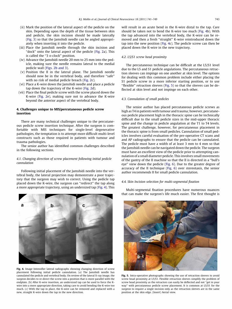
Fig. 4. Image Intensifier lateral radiographs showing changing direction of screwplacement following initial pedicle cannulation. (a) The Jamshidi needle hascannulated the pedicle and vertebral body. On review of the lateral X-ray image, thesurgeon decides to re-direct the screw into a position that is more parallel with theendplate. (b) After K-wire insertion, an undersized tap can be used to force the K-wire into a more appropriate direction, taking care to avoid bending the K-wire toomuch. (c) With the tap in place, the K-wire can be removed and replaced with anew, straight K-wire down the tap in the new direction.
will result in an acute bend in the K-wire distal to the tap. Careshould be taken not to bend the K-wire too much (Fig. 4b). Withthe tap advanced into the vertebral body, the K-wire can be re-moved and then a fresh ‘‘straight’’ K-wire reintroduced down thetap into the new position (Fig. 4c). The pedicle screw can then beplaced down the K-wire in the new trajectory.
4.2. L5/S1 screw head proximity
The percutaneous technique can be difficult at the L5/S1 leveldue to the L5 and S1 pedicle angulations. The percutaneous retrac-tion sleeves can impinge on one another at skin level. The optionsfor dealing with this common problem include either placing theS1 pedicle screw in a more inferior starting position, or to use‘‘flexible’’ retraction sleeves (Fig. 5) so that the sleeves can be de-flected at skin level and not impinge on each other.
4.3. Cannulation of small pedicles
The senior author has placed percutaneous pedicle screws ashigh as T4 in patients with tumour and trauma; however, percutane-ous pedicle placement high in the thoracic spine can be technicallydifficult due to the small pedicle sizes in the mid-upper thoracicspine and the change in pedicle angulation at the T1 to T4 levels.The greatest challenge, however, for percutaneous placement inthe thoracic spine is from small pedicles. Cannulation of small ped-icles involves careful evaluation of the pre-operative CT scans andand AP radiographs to ensure that the pedicle can be cannulated.The pedicle must have a width of at least 3 mm to 4 mm so thatthe Jamshidi needle can be navigated down the pedicle. The surgeonmust have an excellent view of the pedicle prior to attempting can-nulation of a small diameter pedicle. This involves small movementsof the gantry of the II machine so that the II is directed in a ‘‘bull’seye’’ view down the pedicle (Fig. 6). Due to the greater degree ofaccuracy of the II technique (Fig. 6) over stereotaxis, the seniorauthor recommends II for small pedicle cannulation.
4.4. Skin Incision selection for multi-segmental fixation
Multi-segmental fixation procedures have numerous nuancesthat can make the surgeon’s life much easier. The first thought is
Fig. 5. Intra-operative photographs showing the use of retraction sleeves to avoidscrew head proximity at L5/S1. Flexible retraction sleeves simplify the problem ofscrew head proximity as the retractors can easily be deflected and not ‘‘get in yourway’’ with percutaneous pedicle screw placement. It is common at L5/S1 for thesurgeon to require a single incision only as the retraction sleeves are in the sameposition at the skin edge. (Insert) Aerial view.

Fig. 6. Anterior/posterior image intensifier (II) radiographs showing percutaneouscannulation of small pedicles. Angulating the II machine so that the surgeon islooking down the pedicle – the ‘‘bulls eye’’ view (arrows) – assists in placement indifficult pedicles. (Insert) The II technique results in highly accurate pedicle screwinsertion – a 5.5 mm screw into a 6 mm pedicle.
Fig. 7. Intra-operative photograph of skin incision for multi-level constructs. Theblack line is showing all four incisions along a straight trajectory – making theinsertion of the rod technically much easier. The white line shows the incisions in astaggered fashion – the rod insertion here will be more difficult.
Fig. 8. Intra-operative photographs showing insertion of rod in a patient requiringmulti-level surgery. (a) Rod insertion can be performed with a semicirculartechnique (arrows), making sure that the rod is under the fascial layer with (b, c)advancing the rod. Always start the insertion at the pedicle screw head that is mostsuperficial/closest to the skin. (d) Aerial view.
Fig. 9. Axial CT scans showing sclerotic pedicles that may result in the necessity forscrew placement using an open technique. (a) The arrow points towards a Jamshidineedle tract created when the Jamshidi needle ‘‘hit’’ a sclerotic bar of bone betweenthe pedicle and vertebral body – safe cannulation of the pedicle/vertebral bodycould not be achieved and a high-speed drill was used to cannulate the pedicle. (b)This pedicle (arrows) was sclerotic – Jamshidi placement required an open screwpositioning.
744 R.J. Mobbs et al. / Journal of Clinical Neuroscience 18 (2011) 741–749
incision selection, as incisions that ‘‘line-up’’ in a straight line(Fig. 7) represent a far easier prospect for rod insertion. The quali-fication here is for patients who have a scoliosis, or trauma, wherethe pedicles may not line up in a straight line. For a single-level fix-ation, the rod insertion is not difficult and is usually not a problem.For multi-level fixation, a staggered line of incision points can re-sult in a difficult rod insertion.
4.5. Insertion of a rod for multi-segmental fixation
Rod insertion for multi-segmental fixation involves the surgeonhaving a brief mental checklist prior to insertion. Removing the rodafter an initial placement can be difficult and time consuming if thesurgeon has to change the length or curvature of the rod prior to are-insertion. The checklist includes:
(i) How long should the rod be? The length between the retrac-tion sleeves should provide a guide to rod length.
(ii) Does the rod require bending before insertion? As a generalrule, the surgeon should try to leave the pedicle screw headsat an equivalent height throughout the construct to aid withease of rod insertion. The exception here is with traumawhere a reduction manoeuvre may be required.
(iii) Initially from which end should the rod be inserted? The rodshould be inserted from the end of the construct where thepedicle screw head is closest to the skin, enabling ease ofinsertion and navigation along the pedicle screw heads(Fig. 8).
(iv) Do I need an additional incision to insert the rod? This isusually not necessary as the rod can be inserted over manylevels via the cranial incision which is usually the mostsuperficial of the pedicle screw insertions.
4.6. Sclerotic pedicle – difficult Jamshidi placement in hard pedicles
Pedicles that are sclerotic or osteopetrotic (‘‘ivory bone’’) can bedifficult in terms of Jamshidi placement. Advancing a Jamshidi intothese pedicles can be frustrating – rarely the percutaneous
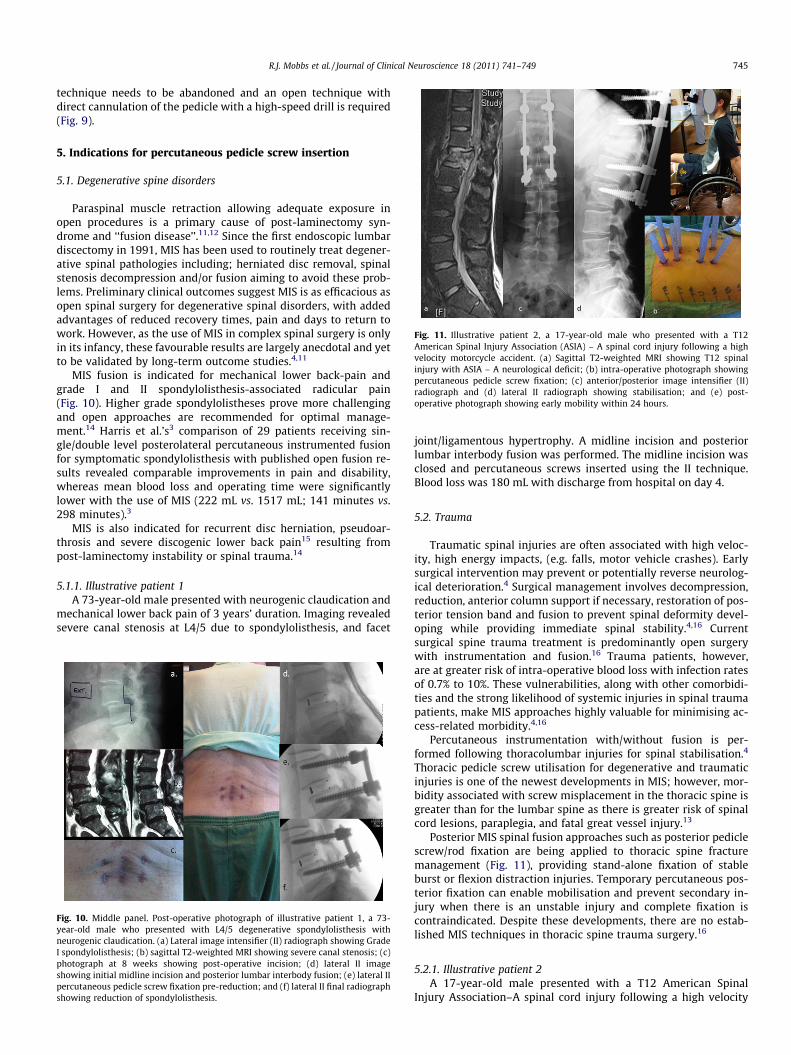
Fig. 11. Illustrative patient 2, a 17-year-old male who presented with a T12American Spinal Injury Association (ASIA) – A spinal cord injury following a highvelocity motorcycle accident. (a) Sagittal T2-weighted MRI showing T12 spinalinjury with ASIA – A neurological deficit; (b) intra-operative photograph showingpercutaneous pedicle screw fixation; (c) anterior/posterior image intensifier (II)radiograph and (d) lateral II radiograph showing stabilisation; and (e) post-operative photograph showing early mobility within 24 hours.
R.J. Mobbs et al. / Journal of Clinical Neuroscience 18 (2011) 741–749 745
technique needs to be abandoned and an open technique withdirect cannulation of the pedicle with a high-speed drill is required(Fig. 9).
5. Indications for percutaneous pedicle screw insertion
5.1. Degenerative spine disorders
Paraspinal muscle retraction allowing adequate exposure inopen procedures is a primary cause of post-laminectomy syn-drome and ‘‘fusion disease’’.11,12 Since the first endoscopic lumbardiscectomy in 1991, MIS has been used to routinely treat degener-ative spinal pathologies including; herniated disc removal, spinalstenosis decompression and/or fusion aiming to avoid these prob-lems. Preliminary clinical outcomes suggest MIS is as efficacious asopen spinal surgery for degenerative spinal disorders, with addedadvantages of reduced recovery times, pain and days to return towork. However, as the use of MIS in complex spinal surgery is onlyin its infancy, these favourable results are largely anecdotal and yetto be validated by long-term outcome studies.4,11
MIS fusion is indicated for mechanical lower back-pain andgrade I and II spondylolisthesis-associated radicular pain(Fig. 10). Higher grade spondylolistheses prove more challengingand open approaches are recommended for optimal manage-ment.14 Harris et al.’s3 comparison of 29 patients receiving sin-gle/double level posterolateral percutaneous instrumented fusionfor symptomatic spondylolisthesis with published open fusion re-sults revealed comparable improvements in pain and disability,whereas mean blood loss and operating time were significantlylower with the use of MIS (222 mL vs. 1517 mL; 141 minutes vs.298 minutes).3
MIS is also indicated for recurrent disc herniation, pseudoar-throsis and severe discogenic lower back pain15 resulting frompost-laminectomy instability or spinal trauma.14
5.1.1. Illustrative patient 1A 73-year-old male presented with neurogenic claudication and
mechanical lower back pain of 3 years’ duration. Imaging revealedsevere canal stenosis at L4/5 due to spondylolisthesis, and facet
Fig. 10. Middle panel. Post-operative photograph of illustrative patient 1, a 73-year-old male who presented with L4/5 degenerative spondylolisthesis withneurogenic claudication. (a) Lateral image intensifier (II) radiograph showing GradeI spondylolisthesis; (b) sagittal T2-weighted MRI showing severe canal stenosis; (c)photograph at 8 weeks showing post-operative incision; (d) lateral II imageshowing initial midline incision and posterior lumbar interbody fusion; (e) lateral IIpercutaneous pedicle screw fixation pre-reduction; and (f) lateral II final radiographshowing reduction of spondylolisthesis.
joint/ligamentous hypertrophy. A midline incision and posteriorlumbar interbody fusion was performed. The midline incision wasclosed and percutaneous screws inserted using the II technique.Blood loss was 180 mL with discharge from hospital on day 4.
5.2. Trauma
Traumatic spinal injuries are often associated with high veloc-ity, high energy impacts, (e.g. falls, motor vehicle crashes). Earlysurgical intervention may prevent or potentially reverse neurolog-ical deterioration.4 Surgical management involves decompression,reduction, anterior column support if necessary, restoration of pos-terior tension band and fusion to prevent spinal deformity devel-oping while providing immediate spinal stability.4,16 Currentsurgical spine trauma treatment is predominantly open surgerywith instrumentation and fusion.16 Trauma patients, however,are at greater risk of intra-operative blood loss with infection ratesof 0.7% to 10%. These vulnerabilities, along with other comorbidi-ties and the strong likelihood of systemic injuries in spinal traumapatients, make MIS approaches highly valuable for minimising ac-cess-related morbidity.4,16
Percutaneous instrumentation with/without fusion is per-formed following thoracolumbar injuries for spinal stabilisation.4
Thoracic pedicle screw utilisation for degenerative and traumaticinjuries is one of the newest developments in MIS; however, mor-bidity associated with screw misplacement in the thoracic spine isgreater than for the lumbar spine as there is greater risk of spinalcord lesions, paraplegia, and fatal great vessel injury.13
Posterior MIS spinal fusion approaches such as posterior pediclescrew/rod fixation are being applied to thoracic spine fracturemanagement (Fig. 11), providing stand-alone fixation of stableburst or flexion distraction injuries. Temporary percutaneous pos-terior fixation can enable mobilisation and prevent secondary in-jury when there is an unstable injury and complete fixation iscontraindicated. Despite these developments, there are no estab-lished MIS techniques in thoracic spine trauma surgery.16
5.2.1. Illustrative patient 2A 17-year-old male presented with a T12 American Spinal
Injury Association–A spinal cord injury following a high velocity
746 R.J. Mobbs et al. / Journal of Clinical Neuroscience 18 (2011) 741–749
motorcycle accident. Stabilisation surgery was performed the dayof presentation with mobilisation and wheelchair rehabilitationwithin 24 hours (Fig. 11). Surgical time was 2 hours, 5 minuteswith 80 mL of blood loss. The patient requested pedicle screw re-moval 12 months following surgery due to discomfort of the ped-icle screw tulips against his wheelchair.
5.3. Spinal neoplasia
Up to 70% of cancer patients show evidence of metastatic dis-ease at death, with 40% having spinal involvement.6 Improvementsin systemic cancer management and imaging is expected to in-crease the incidence of spinal metastases detection.4 Metastaticspine disease arises most commonly in the thoracic spine (thoracic70%; lumbar 20%; cervical 10%) with 10% to 20% suffering symp-tomatic cord compression causing neurological dysfunction anddebilitating pain requiring treatment.4,6
Studies on metastatic spinal disease show better functional out-comes following surgical decompression/stabilisation prior to radi-ation than radiation alone (84% vs. 57%). Surgery prolongs survival,maintains continence and reduces corticosteroids and analgesicuse.6 Oncology patients often suffer multiple comorbidities, so ef-forts to reduce surgical morbidity are essential.16 Although treat-ment is often palliative, it is crucial in improving quality of life(QOL) by improving pain and ambulatory function.4 Thus, theadvantages of MIS, including smaller incisions limiting woundcomplications, are crucial for maintaining/improving the QOL ofcancer patients with a mean survival of only 8 to 12 months.4,6
Another recently introduced stabilisation technique for spinalneoplasia utilises percutaneous instrumentation with cementreconstruction and/or placement of intervertebral structural grafts.The combination of increasingly available MIS management op-tions (Fig. 12), and chemo/radiotherapy will likely improve spinalcancer treatment.4
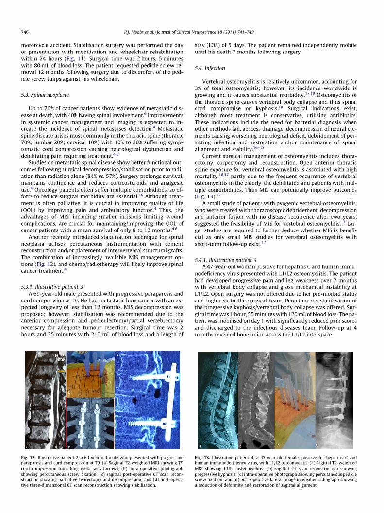
5.3.1. Illustrative patient 3A 69-year-old male presented with progressive paraparesis and
cord compression at T9. He had metastatic lung cancer with an ex-pected longevity of less than 12 months. MIS decompression wasproposed; however, stabilisation was recommended due to theanterior compression and pediculectomy/partial vertebrectomynecessary for adequate tumour resection. Surgical time was 2hours and 35 minutes with 210 mL of blood loss and a length of
Fig. 12. Illustrative patient 2, a 69-year-old male who presented with progressiveparaparesis and cord compression at T9. (a) Sagittal T2-weighted MRI showing T9cord compression from lung metastasis (arrow); (b) intra-operative photographshowing percutaneous screw fixation; (c) sagittal post-operative CT scan recon-struction showing partial vertebrectomy and decompression; and (d) post-opera-tive three-dimensional CT scan reconstruction showing stabilisation.
stay (LOS) of 5 days. The patient remained independently mobileuntil his death 7 months following surgery.
5.4. Infection
Vertebral osteomyelitis is relatively uncommon, accounting for3% of total osteomyelitis; however, its incidence worldwide isgrowing and it causes substantial morbidity.17,18 Osteomyelitis ofthe thoracic spine causes vertebral body collapse and thus spinalcord compromise or kyphosis.16 Surgical indications exist,although most treatment is conservative, utilising antibiotics.These indications include the need for bacterial diagnosis whenother methods fail, abscess drainage, decompression of neural ele-ments causing worsening neurological deficit, debridement of per-sisting infection and restoration and/or maintenance of spinalalignment and stability.16–18
Current surgical management of osteomyelitis includes thora-cotomy, corpectomy and reconstruction. Open anterior thoracicspine exposure for vertebral osteomyelitis is associated with highmortality,16,17 partly due to the frequent occurrence of vertebralosteomyelitis in the elderly, the debilitated and patients with mul-tiple comorbidities. Thus MIS can potentially improve outcomes(Fig. 13).17
A small study of patients with pyogenic vertebral osteomyelitis,who were treated with thoracoscopic debridement, decompressionand anterior fusion with no disease recurrence after two years,suggested the feasibility of MIS for vertebral osteomyelitis.17 Lar-ger studies are required to further deduce whether MIS is benefi-cial as only small MIS studies for vertebral osteomyelitis withshort-term follow-up exist.17
5.4.1. Illustrative patient 4A 47-year-old woman positive for hepatitis C and human immu-
nodeficiency virus presented with L1/L2 osteomyelitis. The patienthad developed progressive pain and leg weakness over 2 monthswith vertebral body collapse and gross mechanical instability atL1/L2. Open surgery was not offered due to her pre-morbid statusand high-risk to the surgical team. Percutaneous stabilisation ofthe progressive kyphosis/vertebral body collapse was offered. Sur-gical time was 1 hour, 55 minutes with 120 mL of blood loss. The pa-tient was mobilised on day 1 with significantly reduced pain scoresand discharged to the infectious diseases team. Follow-up at 4months revealed bone union across the L1/L2 interspace.
Fig. 13. Illustrative patient 4, a 47-year-old female, positive for hepatitis C andhuman immunodeficiency virus, with L1/L2 osteomyelitis. (a) Sagittal T2-weightedMRI showing L1/L2 osteomyelitis; (b) sagittal CT scan reconstruction showingprogressive kyphosis; (c) intra-operative photograph showing percutaneous pediclescrew fixation; and (d) post-operative lateral image intensifier radiograph showinga reduction of deformity and restoration of sagittal alignment.

Fig. 15. Illustrative patient 6, a 48-year-old male who presented with ongoing backpain and evidence of a non-union following a L5/S1 stand-alone posterior lumbarinterbody fusion (PLIF). (a) Lateral image intensifier (II) intra-operative radiographshowing pedicle screw fixation and posterolateral graft. (b, c) Intra-operativephotographs showing completion of procedure prior to removal of tubular dilators.(d) Post-operative photograph at 10 weeks showing previous midline incision andbilateral revision fixation using minimally invasive surgery.
R.J. Mobbs et al. / Journal of Clinical Neuroscience 18 (2011) 741–749 747
5.5. Obesity
All spinal operations prove more difficult in patients with obes-ity,9 and they have increased complication risks including surgicalsite infection following fusion. However, MIS posterior lumbar fu-sion is especially useful for these patients.13,19 Open posterior lum-bar fusions require longer incisions to access the deeper spine inobese patients.9,19 Tubular retraction systems used in MIS, how-ever, enable the use of similarly sized incisions for all patients.Shorter incisions minimise surgical cavity size, reduce soft-tissuetrauma, and produce an instrument-only surgical field, reducingcomplications experienced by obese patients, including woundinfections.9,19 Excessive body weight also requires longer operatingtimes for open posterior lumbar spine fusion, but no significant dif-ference in operative times for MIS techniques, as the greater skin tospine distance does not require additional dissection time whenusing minimally invasive tubular retractor systems.19 These advan-tages indicate the use of MIS in obese patients (Fig. 14).
5.5.1. Illustrative patient 5A 59-year-old male presented with mechanical back pain, uni-
lateral L5 radiculopathy due to lateral recess stenosis and an ele-vated body mass index. MIS–transforaminal lumbar interbodyfusion (TLIF) was recommended to avoid a lengthy incision andprolonged hospital stay. Surgical time was 4 hours and 50 minuteswith 240 mL of blood loss. LOS was 3 days. Frameless stereotaxiswas used to assist with percutaneous pedicle screw placement.
5.6. Revision surgery
Revision surgery is often more technically challenging becauseof local scarring and greater complication rates such as nerve rootinjury and incidental durotomy. Along with altered anatomy, ab-sent bony landmarks and limited surgical exposure, it is no sur-prise that surgeons avoid MIS approaches for revision surgery.8,9
Lumbar interbody fusions are indicated for revision surgery ofrecurrent disc herniation and post-laminectomy instability. Selz-nick et al.’s study8 of 43 patients who underwent minimally inva-sive posterior lumbar interbody fusion (PLIF) or TLIF, compared the
Fig. 14. Illustrative patient 5, 59-year-old, 135 kg male, who presented withmechanical back pain, unilateral L5 radiculopathy due to lateral recess stenosis andan elevated body mass index who underwent a transforaminal lumbar interbodyfusion (TLIF). (a) Left – anterior/posterior (AP) image intensifier (II) radiograph, andright – lateral II radiograph showing L4/5 TLIF plus pedicle screw fixation; (b) 6-month post-operative photograph of the patient standing; (c) close-up of 4 cmbilateral incision, plus bone graft harvest, scars.
outcomes following primary surgery to revision surgery at a prioroperative level. The primary surgery group consisted of 26 patientsundergoing operations for degenerative spondylolisthesis andspondylolysis, degenerative scoliosis. The revision surgery groupconsisted of 17 patients with the primary indications for the sur-gery being post-laminectomy instability and multiple recurrentdisc herniations. They concluded that minimally invasive lumbarinterbody fusion is a possible option for revision surgery, withoutsignificantly higher rates of blood loss, transfusion, infection orneurological complications compared to primary surgery. How-ever, minimally invasive revision lumbar interbody fusions hadsignificantly higher complication rates, with the risk of inadvertentdurotomy and cerebrospinal fluid (CSF) leak approximately sixtimes higher than in the primary surgery cohort. All CSF leaks werefixed intra-operatively without developing into a pseudomeningo-cele or requiring further surgery.8
It is recommended that surgeons gain substantial experiencewith MIS techniques of primary patients, before attempting mini-mally invasive revision interbody fusion of the lumbar spine.8,9
Surgeons attempting minimally invasive revision surgery(Fig. 15) should also be ready to convert to wider exposures if nec-essary, for safe exposure of the relevant spinal region.9
5.6.1. Illustrative patient 6A 48-year-old male presented with ongoing back pain and evi-
dence of a non-union following a L5/S1 stand-alone PLIF. Revisionfusion with percutaneous pedicle screws and on-lay bone graftover the L5/S1 facet joints was recommended. Operating timewas 1 hour, 40 minutes with 100 mL of blood loss. LOS was 3 days.Significant immediate reduction in mechanical back pain wasexperienced, with return to work within 6 weeks.
5.7. MIS grafting
Autografts involve transferring bone within the same individ-ual.20 Throughout the 1990s, as spinal fusion rates rose, bone graft

Fig. 16. Illustrative patient 7, a 72-year-old female who presented with neurogenicclaudication and L4/5 grade 1 spondylolisthesis. (a) Intra-operative photographshowing the minimally invasive surgery grafting technique for a posterolateralgraft. (b, c, d) Lateral intra-operative image intensifier radiographs showing (b) drillpreparation of facet joints; (c) insertion of graft packing tube; and (d) position ofposterolateral graft. (e) Axial post-operative CT scan with graft overlay on facetjoint.
Fig. 17. Illustrative patient 8, a 54-year-old male who presented with mechanicallow back pain secondary to L4/5 facet joint arthrosis with a mobile spondylolis-thesis, resistant to multiple conservative therapies. Pedicle screw based motionsparing techniques showing: (a) lateral image intensifier (II) radiograph showinginstability on flexion (left) and extension (right) views at L4/5. (b) Radioisotopebone scan uptake at L4/5 facet joints. (c) Final intra-operative lateral II view ofDynamic Stabilization Systems (DSS™, Paradigm Spine, Wurmlingen, Germany)implant system. (d) Intra-operative photograph showing tubular dilators.
748 R.J. Mobbs et al. / Journal of Clinical Neuroscience 18 (2011) 741–749
harvests were most commonly used for spinal arthrodesis.21,22
With fusion, the gaps between host bone and graft fill via new boneformation and with more bone deposition and remodelling on theosteoconductive matrix, segmental stiffness increases. Thus, spinalbone grafting is a race between fusion healing and failure of inter-nal fixation to immobilise spinal elements.20
An adequate blood supply is necessary to encourage healing.Excessive muscle stripping and devascularisation limits oxygen,nutrient, neovascularisation and cellular migration to the fusionmass. Significant muscle necrosis may also provide environmentssuitable for bacterial growth, which compete for nutrients andinterfere with the inflammatory processes necessary for the devel-oping fusion mass, thus causing graft failure.20 MIS, which aims tominimise blood loss, muscle stripping and necrosis thus promotessuccessful fusion (Fig. 16). With the limited number of studiesavailable, however, it is suggested that evidence based medicineguide the use of bone grafts and bone morphogenic protein in min-imally invasive spinal fusion.13
5.7.1. Illustrative patient 7A 72-year-old woman presented with neurogenic claudication
and L4/5 grade 1 spondylolisthesis. Decompression and postero-lateral onlay fusion was recommended. Interbody fusion was notrecommended due to poor bone mineral density. Following a mid-line MIS decompression, percutaneous pedicle screws were in-serted and postero-lateral bone graft onlay was performed viathe retraction tubes for the pedicle screw system.
5.8. Emerging technology
Despite the benefits of MIS fusion in well-selected patients,there are limitations which include: accelerated adjacent leveldegeneration, symptomatic pseudoarthrosis and graft site morbid-ity.22,23 Motion sparing techniques now offer improved stabilityand intersegmental motion compared to current fusion opera-tions,24,25 following procedures for degenerative disc disease,spinal stenosis and spondylolisthesis.22,23,25 This allows surgeonsto avoid the aforementioned limitations, while treating patientsat earlier stages of degeneration than traditional fusion. Further-more, motion-sparing techniques like pedicle screw-based systems
can be inserted via minimally invasive paraspinal techniques, thusavoiding significant muscle and ligament damage.23
Although similar to rigid pedicle screw systems, posterior dy-namic stabilisation (PDS), including pedicle screw-based stabilisa-tion (Fig. 17), aims to relieve pain, other compressive neurologicalsymptoms, and restore stabilisation by re-establishing the naturalanatomic position and enabling restricted segmental motion.22,23
In contrast to fusion systems that aim to withstand loading untilfusion occurs, pedicle screws in dynamic stabilisation systemsneed to withstand cyclical loading indefinitely, which makes thescrews prone to loosening.22
As the PDS technology has only recently emerged, the availableliterature is sparse with most studies having only 2 years of follow-up at most.24,25 Furthermore, it may take 5 years to 10 years beforethe beneficial effects of PDS, like adjacent segment degeneration,can be detected when compared with rigid forms of spinal fusion.Thus, multiple, similarly designed trials need to be undertaken be-fore any conclusions about the benefits of PDS over current fusiontechniques can be drawn.25
5.8.1. Illustrative patient 8A 54-year-old male presented with mechanical low back pain
secondary to L4/5 facet joint arthrosis with a mobile spondylolis-thesis, resistant to many years of multiple conservative therapies.A posterior, motion-sparing dynamic stabilising implant was of-fered as an alternative to fusion. The operating time was 2 hours,25 minutes with 110 mL of blood loss. Follow-up at 3 months re-vealed no instability on flexion/extension radiographs with moder-ate reduction in low back pain scores.
6. Discussion
Since 2000, the techniques of minimally invasive spinal fusionhave improved substantially. With increasing experience, indica-tions for minimally invasive spinal fusion have expanded.4,10 Cur-rently, indications are similar to those for open surgery andstrongly rely on the surgeon’s experience with the procedure.14
Most MIS spinal techniques have steep learning curves, requiringdifferent cognitive, psychomotor and technical skills.6,9,13 It is
R.J. Mobbs et al. / Journal of Clinical Neuroscience 18 (2011) 741–749 749
recommended that surgeons have adequate experience with openprocedures before attempting minimally invasive methods14 andthat they begin with simple MIS procedures. Depending on theprocedure, the patient and the surgeon’s experience, MIS may takemore time to perform than open surgery.9
As indications for percutaneous pedicle screw techniques ex-pand, the nuances of the MIS technique will also expand. It is par-amount that experienced surgeons share their collectiveknowledge to assist surgeons at their early attempts of these com-plex, and potentially very dangerous procedures.
MIS aims to minimise surgery-associated risk and morbidity,including irreversible muscle injury from muscle stripping andretraction, which are associated with poor clinical results, whileachieving the same results as conventional approaches.6,8,10,16 De-spite encouraging clinical results, MIS techniques are in their in-fancy with the results being preliminary at best. Prospectiveoutcome studies with long-term follow-up comparing new mini-mally invasive spinal fusion to conventional open fusions are re-quired to ultimately determine the safety, effectiveness andclinical benefit of minimally invasive spinal fixation.4,5,17
7. Conclusion
Spinal fusion is the gold standard in maintaining the stability ofunstable spinal segments for multiple potential pathologies. As thetechniques and instruments in MIS spinal surgery have evolved,the indications for minimally invasive spinal fusion have expandedto include: degeneration, trauma, deformity, infection and neopla-sia. With technological advancements, it is expected that MIS fu-sion techniques will become a prominent part of spinal surgeryand that indications for minimally invasive spinal fusion will ex-pand. This review adds to the literature to inform prospective sur-geons of the nuances of the percutaneous technique for pediclescrew insertion.
References
1. Kanter AS, Mummaneni PV. Minimally invasive spine surgery. Neurosurg Focus2008;25:E1.
2. Mayer HM. A new microsurgical technique for minimally invasive anteriorlumbar interbody fusion. Spine 1997;22:691–700.
3. Harris EB, Massey P, Lawrence J, et al. Percutaneous techniques for minimallyinvasive posterior lumbar fusion. Neurosurg Focus 2008;25:E12.
4. Hsieh PC, Koski TR, Sciubba DM, et al. Maximizing the potential of minimallyinvasive spine surgery in complex spinal disorders. Neurosurg Focus 2008;25:E19.
5. Lipson SJ. Spinal-fusion surgery – advances and concerns. N Engl J Med2004;350:643–4.
6. Kan P, Schmidt MH. Minimally invasive thoracoscopic approach for anteriordecompression and stabilization of metastatic spine disease. Neurosurg Focus2008;25:E8.
7. Assaker R. Minimal access spinal technologies: state-of-the-art, indications, andtechniques. Joint Bone Spine 2004;71:459–69.
8. Selznick LA, Shamji MF, Isaacs RE. Minimally invasive interbody fusion forrevision lumbar surgery: technical feasibility and safety. J Spinal Disord Tech2009;22:207–13.
9. Kerr SM, Tannoury C, White AP, et al. The role of minimally invasive surgery inthe lumbar spine. Oper Tech Orthop 2007;17:183–9.
10. Beisse R. Endoscopic surgery on the thoracolumbar junction of the spine. EurSpine J 2006;15:687–704.
11. Foley KT, Holly LT, Schwender JD. Minimally invasive lumbar fusion. Spine2003;28:S26–35.
12. Foley KT, Gupta SK. Percutaneous pedicle screw fixation of the lumbar spine:preliminary clinical results. J Neurosurg 2002;97(Suppl. 1):7–12.
13. Oppenheimer JH, DeCastro I, McDonnell DE. Minimally invasive spinetechnology and minimally invasive spine surgery: a historical review.Neurosurg Focus 2009;27:E9.
14. Holly LT, Schwender JD, Rouben DP, et al. Minimally invasive transforaminallumbar interbody fusion: indications, technique, and complications. NeurosurgFocus 2006;20:E6.
15. Regan JJ, Yuan H, McAfee PC. Laparoscopic fusion of the lumbar spine:minimally invasive spine surgery. A prospective multicenter study evaluatingopen and laparoscopic lumbar fusion. Spine 1999;24:402–11.
16. Smith JS, Ogden AT, Fessler RG. Minimally invasive posterior thoracic fusion.Neurosurg Focus 2008;25:E9.
17. Swanson AN, Pappou IP, Cammisa FP, et al. Chronic infections of the spine:surgical indications and treatments. Clin Orthop Relat Res 2006;444:100–6.
18. Cowan JA, Thompson BG. Neurosurgery. The McGraw-Hill Companies; 2010.Chapter 36.
19. Rosen DS, Ferguson SD, Ogden AT, et al. Obesity and self-reported outcomeafter minimally invasive lumbar spinal fusion surgery. Neurosurgery2008;63:956–60.
20. Vaccaro AR, Chiba K, Heller JG, et al. Bone grafting alternatives in spinalsurgery. Spine J 2002;2:206–15.
21. Sandhu HS, Grewal HS, Parvataneni H. Bone grafting for spinal fusion. OrthopClin North Am 1999;30:685–98.
22. Meyers K, Tauber M, Sudin Y, et al. Use of instrumented pedicle screws toevaluate load sharing in posterior dynamic stabilization systems. Spine J2008;8:926–32.
23. Bertagnoli R, Fantini GA, Brau SA, et al. Spinal motion preservation technologies:surgical approach and procedure. Chapter 22. In: Nucleus arthroplasty. VolumeIV: Emerging technologies. Minneapolis, MN, USA: Raymedica; 2007. p. 7–14.Available from: http://www.thesona.com/V4_V5-Final.pdf.
24. Heary RF. Dynamic stabilization. Neurosurg Focus 2010;28:E1.25. Bono CM, Kadaba M, Vaccaro AR. Posterior pedicle fixation-based dynamic
stabilization devices for the treatment of degenerative diseases of the lumbarspine. J Spinal Disord Tech 2009;22:376–83.