Embed Size (px)
Citation preview
May 2009
NASA/TM-2009-215751 NESC-RP-08-75/06-069-I
Guidelines on Lithium-ion Battery Use in Space Applications Barbara McKissock, Patricia Loyselle, and Elisa Vogel Glenn Research Center, Cleveland, Ohio
https://ntrs.nasa.gov/search.jsp?R=20090023862 2018-05-11T08:34:19+00:00Z
NASA STI Program . . . in Profile
Since its founding, NASA has been dedicated to the advancement of aeronautics and space science. The NASA scientific and technical information (STI) program plays a key part in helping NASA maintain this important role.
The NASA STI program operates under the auspices of the Agency Chief Information Officer. It collects, organizes, provides for archiving, and disseminates NASA’s STI. The NASA STI program provides access to the NASA Aeronautics and Space Database and its public interface, the NASA Technical Report Server, thus providing one of the largest collections of aeronautical and space science STI in the world. Results are published in both non-NASA channels and by NASA in the NASA STI Report Series, which includes the following report types:
• TECHNICAL PUBLICATION. Reports of
completed research or a major significant phase of research that present the results of NASA programs and include extensive data or theoretical analysis. Includes compilations of significant scientific and technical data and information deemed to be of continuing reference value. NASA counterpart of peer-reviewed formal professional papers, but having less stringent limitations on manuscript length and extent of graphic presentations.
• TECHNICAL MEMORANDUM. Scientific
and technical findings that are preliminary or of specialized interest, e.g., quick release reports, working papers, and bibliographies that contain minimal annotation. Does not contain extensive analysis.
• CONTRACTOR REPORT. Scientific and
technical findings by NASA-sponsored contractors and grantees.
• CONFERENCE PUBLICATION. Collected
papers from scientific and technical conferences, symposia, seminars, or other meetings sponsored or co-sponsored by NASA.
• SPECIAL PUBLICATION. Scientific,
technical, or historical information from NASA programs, projects, and missions, often concerned with subjects having substantial public interest.
• TECHNICAL TRANSLATION. English-
language translations of foreign scientific and technical material pertinent to NASA’s mission.
Specialized services also include creating custom thesauri, building customized databases, and organizing and publishing research results. For more information about the NASA STI program, see the following: • Access the NASA STI program home page at
http://www.sti.nasa.gov • E-mail your question via the Internet to
[email protected] • Fax your question to the NASA STI Help Desk
at 443-757-5803 • Phone the NASA STI Help Desk at
443-757-5802 • Write to:
NASA STI Help Desk NASA Center for AeroSpace Information 7115 Standard Drive Hanover, MD 21076-1320
National Aeronautics and Space Administration Langley Research Center Hampton, Virginia 23681-2199
May 2009
NASA/TM-2009-215751 NESC-RP-08-75/06-069-I
Guidelines on Lithium-ion Battery Use in Space Applications Barbara McKissock, Patricia Loyselle, and Elisa Vogel Glenn Research Center, Cleveland, Ohio
Available from:
NASA Center for AeroSpace Information 7115 Standard Drive
Hanover, MD 21076-1320 443-757-5802
The use of trademarks or names of manufacturers in the report is for accurate reporting and does not constitute an official endorsement, either expressed or implied, of such products or manufacturers by the National Aeronautics and Space Administration.
NASA Engineering and Safety CenterTechnical Report
Document #:
RP-08-75
Version:
1.0
Title:
NASA Aerospace Flight Battery Program Page #:
1 of 49
NESC Request No.:06-069-I
Guidelines on Lithium-ion Battery Use in Space Applications
NASA Engineering Safety Center Battery Working Group
Prepared by
Barbara McKissock, Patricia Loyselle, and Elisa Vogel NASA Glenn Research Center
MARCH 2008
NASA Engineering and Safety Center Technical Report
Document #:
RP-08-75 Version:
1.0
Title:
NASA Aerospace Flight Battery Program Page #:
2 of 49
NESC Request No.: 06-069-I
TABLE OF CONTENTS 1. Introduction.............................................................................................................................................3 2. Basic Chemical Information ..................................................................................................................3 3. Factors affecting battery performance .................................................................................................6 4. Battery Design ....................................................................................................................................... 10 5. Hazards and Controls........................................................................................................................... 11 6. Battery Requirements........................................................................................................................... 14 7. Cell/battery handling and procedures.................................................................................................24 8. Testing....................................................................................................................................................27 9. References..............................................................................................................................................45 Appendix A: Definitions ...........................................................................................................................46
NASA Engineering and Safety Center Technical Report
Document #:
RP-08-75 Version:
1.0
Title:
NASA Aerospace Flight Battery Program Page #:
3 of 49
NESC Request No.: 06-069-I
1. Introduction Purpose This guideline discusses a standard approach for defining, determining, and addressing safety, handling, and qualification standards for lithium-ion (Li-Ion) batteries to help the implementation of the technology in aerospace applications. Information from a variety of other sources relating to Li-ion batteries and their aerospace uses has been collected and included in this document. The sources used are listed in the reference section at the end of this document. The Li-Ion chemistry is highly energetic due to its inherent high specific energy and its flammable electrolyte. Due to the extreme importance of appropriate design, test, and hazard control of Li-ion batteries, it is recommended that all Government and industry users and vendors of this technology for space applications, especially involving humans, use this document for appropriate guidance prior to implementing the technology. Additional work is continuing to determine controls and testing needed for the safe use of Li-ion batteries. In addition, continuing changes in cell chemistry that affect the safe use and handling of Li-ion technology are occurring that will need to be addressed. The guidelines should be revisited and revised in one year to incorporate any newly developed recommendations. Applications Li-ion batteries are rechargeable (secondary) batteries. Secondary batteries are used as energy-storage devices, generally connected to and charged by a prime energy source, delivering their energy to the load on demand. Secondary batteries are also used in applications where they provide power remotely from a separate power source that they return to periodically for recharge. Aerospace applications include power for satellites, astronaut suits (extravehicular activities), planetary and lunar rovers, and surface systems during night-time or peak power operations. Payloads, launch vehicles, and portable devices, such as computers and camcorders, may also use secondary batteries in place of primary batteries for cost savings, to handle power levels beyond the capability of conventional primary batteries, or because of activation, rate capability, or life issues. Li-Ion batteries were more commonly used in portable electronic equipment in the 1990s and towards the late 90s they began acceptance for powering launch and satellite systems.
2. Basic Chemical Information There are a wide number of chemistries used in Li-Ion batteries. Li-Ion batteries avoid the reactivity, safety, and abuse sensitivity issues involved with the use of lithium metal cathodes by using a suitable alloy that allows intercalation of lithium ions; no metallic lithium is present in the cell, with normal operation. Li-Ion batteries with liquid electrolyte are rechargeable batteries and have a cathode of various classes of materials that include layered LiMO2 (M = Co,
NASA Engineering and Safety Center Technical Report
Document #:
RP-08-75 Version:
1.0
Title:
NASA Aerospace Flight Battery Program Page #:
4 of 49
NESC Request No.: 06-069-I
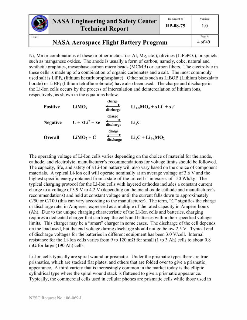
Ni, Mn or combinations of these or other metals, i.e. Al, Mg, etc.), olivines (LiFePO4), or spinels such as manganese oxides. The anode is usually a form of carbon, namely, coke, natural and synthetic graphites, mesophase carbon micro beads (MCMB) or carbon fibers. The electrolyte in these cells is made up of a combination of organic carbonates and a salt. The most commonly used salt is LiPF6 (lithium hexafluorophosphate). Other salts such as LiBOB (Lithium bisoxalato borate) or LiBF4 (lithium tetrafluoroborate) have also been used. The charge and discharge in the Li-Ion cells occurs by the process of intercalation and deintercalation of lithium ions, respectively, as shown in the equations below.
Positive LiMO2 charge
discharge
charge
discharge Li1-xMO2 + xLi+ + xe-
Negative C + xLi+ + xe- charge
discharge
charge
discharge LixC
Overall LiMO2 + C charge
discharge
charge
discharge LixC + Li1-xMO2 The operating voltage of Li-Ion cells varies depending on the choice of material for the anode, cathode, and electrolyte; manufacturer’s recommendations for voltage limits should be followed. The capacity, life, and safety of a Li-Ion battery will also vary based on the choice of component materials. A typical Li-Ion cell will operate nominally at an average voltage of 3.6 V and the highest specific energy obtained from a state-of-the-art cell is in excess of 150 Wh/kg. The typical charging protocol for the Li-Ion cells with layered cathodes includes a constant current charge to a voltage of 3.9 V to 4.2 V (depending on the metal oxide cathode and manufacturer’s recommendations) and held at constant voltage until the current falls down to approximately C/50 or C/100 (this can vary according to the manufacturer). The term, “C” signifies the charge or discharge rate, in Amperes, expressed as a multiple of the rated capacity in Ampere-hours (Ah). Due to the unique charging characteristic of the Li-Ion cells and batteries, charging requires a dedicated charger that can keep the cells and batteries within their specified voltage limits. This charger may be a “smart” charger in some cases. The discharge of the cell depends on the load used, but the end voltage during discharge should not go below 2.5 V. Typical end of discharge voltages for the batteries in different equipment has been 3.0 V/cell. Internal resistance for the Li-Ion cells varies from 9 to 120 mΩ for small (1 to 3 Ah) cells to about 0.8 mΩ for large (190 Ah) cells. Li-Ion cells typically are spiral wound or prismatic. Under the prismatic types there are true prismatics, which are stacked flat plates, and others that are folded over to give a prismatic appearance. A third variety that is increasingly common in the market today is the elliptic cylindrical type where the spiral wound stack is flattened to give a prismatic appearance. Typically, the commercial cells used in cellular phones are prismatic cells while those used in
NASA Engineering and Safety Center Technical Report
Document #:
RP-08-75 Version:
1.0
Title:
NASA Aerospace Flight Battery Program Page #:
5 of 49
NESC Request No.: 06-069-I
camcorders, cameras, and PCs are cylindrical cells. Li-Ion cells have 100% energy efficiency through most of their cycle life (input energy is equal to output energy). Most commercial cylindrical cells are case negative, although some that have aluminum cases are case positive. Most of the prismatic cells above 5Ah capacity are case neutral. The state-of-charge (SOC) and temperature at which the cells are stored or cycled greatly affects the irreversible capacity loss in the cells. For example, one commercial cell in a period of storage for one year, exhibited less than 2 % loss at 0 % SOC and 0 ºC, whereas it was about 13 % loss at 100 % SOC and 40 ºC. The temperature and the depth of discharge to which the cells are cycled also affect the deliverable capacity of the cells with cycle life. Li-Ion polymer batteries are rechargeable batteries that have polymer blends in the cathode or anode or separator or in all three. In the polymer cells, flat, bonded electrodes are used to enable the fabrication of thin cells. The cells are made in flexible shapes and sizes and packaged in aluminized plastic pouches. The electrochemical nature of these cells is very similar to the liquid li-ion cells discussed previously. These cells have a LiMO
2 cathode (M = Co, Ni, Mn or
combinations of these). The commonly used cathodes in li-ion polymer cells are LiMn2O
4 spinel
compounds. The anode can be any form of carbon, namely, natural and synthetic graphites, mesophase carbon micro beads (MCMB) or carbon fibers (li-ion polymer cells). The anode can also be lithium metal (lithium polymer cells). The electrolyte in these cells is made up of a combination of organic carbonates and a salt in a polymer matrix. The most commonly used salt is LiPF
6 (lithium hexafluorophosphate). The polymers commonly used are based on
polyacrylonitriles (PANs), PVDF based polymers (PVDF-HFP, PVDF-CTFE), polyvinyl chloride (PVC), etc. In some cases, an ancillary plasticizer such as dibutyl phthalate is incorporated into the resin, which facilitates the densification of the electrodes under low temperature and pressure. The plasticizer is later vaporized or removed by a suitable solvent extraction process. The nominal voltage of the Li-Ion polymer cells with the cobaltate cathode is about 3.6 V and the energy density obtained can range from 145 to 190 Wh/kg. The Li-Ion polymer cells with the manganese spinel cathode have a nominal voltage of about 3.8 V and have energy densities in the range of 130 to 144 Wh/kg. The typical charging protocol for the lithium/Li-Ion polymer cells includes a constant current charge to a voltage of 4.1 V or 4.2 V (depending on the metal oxide cathode and manufacturer’s recommendations) and held at constant voltage until the current falls to approximately C/100 (this can vary according to the manufacturer). Similarly to the li-ion cells with liquid electrolyte, charging of li-ion polymer cells requires a dedicated charger due to their unique charging characteristics. This charger can be a “smart” charger in some cases. The discharge of the cell depends on the load used but the end voltage during discharge should not go below 2.5 V. Typical end-of-discharge voltages for the batteries in different equipment have been 3.0 V/cell. Internal resistance for the li-ion polymer cells varies from 20 to 60 mΩ for small (0.5 to 15 Ah) cells and is expected to drop with increased capacity cells.
NASA Engineering and Safety Center Technical Report
Document #:
RP-08-75Version:
1.0
Title:
NASA Aerospace Flight Battery Program Page #:
6 of 49
NESC Request No.: 06-069-I
Advances in cathode and anode materials have led to the development of new Li-Ion cell chemistries. Such changes also cause a change in voltage. The Olivine cathode is one such with its LiFePO4 cathode. The operating voltage of the LiFePO4 type li-ion cell is 3.3 V. Changing anode materials from graphite to titanate-based materials as in the Altairnano cells is another example where the operating voltage drops to 2.65 V. Li-Ion polymer cells are typically flat and thin. The cells are packaged in vapor-impermeable, flexible, multilayer polymer-aluminum bags. The polymer cells are typically made up of a positive electrode plate and a negative electrode plate bonded to two opposite sides of an ionically conductive separator. The plates can be stacked as individual plates, Z-folded, or folded in other ways depending on the mechanical properties of the individual component layers. A large capacity cell would thus have several plates stacked on each other to give the capacity required. Another common method of cell stacking is the “bicell” configuration where the central plate (typically a negative electrode) is shared by two positive plates on either side. There is a layer of separator between the center negative plate and the two positive plates on either side. Several bicells can be stacked to give a larger capacity cell. Polymer cells typically perform well at low rates of charge and discharge. However, cells can be made for specific medium and high rate applications. Because of the higher resistance caused by the polymer materials used in the electrodes and separator, currently, a small quantity of liquid electrolyte is used to improve ionic conductivity. The state-of-charge (SOC) and temperature at which the cells are stored or cycled greatly affects the irreversible capacity loss in the cells. These are similar to the liquid li-ion cells.
3. Factors affecting battery performance The performance required from the battery for a specific application should be determined and the relative importance of the different factors should be prioritized prior to selection of the cell to be used, since they interact with each other. For example, operational factors such as temperature and charge/discharge rate affect other factors such as capacity, voltage, and life. Typically, testing is required to confirm battery performance at the specific conditions of the application. General interactions of these factors are discussed here; information on the performance of specific cells at defined conditions can be requested from manufacturers. CapacityCapacity is adversely affected by high storage temperatures, high state-of-charge during storage, higher discharge rates, low temperature during charging, the stand time between charge and discharge, and operation at temperatures either lower or higher than the cell optimum temperature.
NASA Engineering and Safety Center Technical Report
Document #:
RP-08-75Version:
1.0
Title:
NASA Aerospace Flight Battery Program Page #:
7 of 49
NESC Request No.: 06-069-I
When a cell is discharged, its voltage while under load is lower than both the theoretical voltage, which is based on its chemical composition, and the open-circuit voltage, where there is no load on the cell. The voltage of the cell decreases during the discharge, and the shape of the discharge voltage curve is affected by temperature, discharge rate, cycle life, service life, and the electrochemical reactions occurring within the cell. The voltage typically is lower and decreases faster with increased discharge rates and longer cycle life. The open-circuit voltage varies with the state-of-charge of the cell. Discharge Current Rate Decreased capacity, voltage, and life and increased IR losses and heating are seen with higher discharge current rates, along with a more rapid decrease in voltage during the discharge. A cell that has been discharged at a higher current rate to a specific cutoff voltage still has additional capacity available above that cutoff voltage if the discharge is continued at a lower current rate. While the theoretical voltage and capacity can be approached with extremely low current rates, very long discharge periods can cause chemical deterioration that would reduce the capacity. Discharge rates are commonly specified as multiples of the C rate, which is the current that will discharge the battery to the cutoff voltage in one hour. Charge Current Rate Less capacity is restored and increased heating occurs when higher charge current rates are used. The magnitudes of the capacity decrease and heating increase are temperature dependent. When a cell is charged at a higher current rate to the end-of-charge voltage, more capacity can be added below the cutoff voltage if the charge is continued at a lower rate. Charge rates are also commonly specified as multiples of the C rate. Continuous or Intermittent Discharge When a battery is allowed to rest after a discharge, certain chemical and physical changes take place that can result in voltage recovery. Thus, the voltage of a battery that has dropped during a high-rate discharge will rise after a rest period. This improvement due to the rest period is generally greater after discharge at higher currents and also is dependent on the end-of-discharge voltage, temperature, and the length of the rest period. Constant Current, Constant Load, or Constant Power Discharge A battery may be discharged using constant current, constant resistance, or constant power loads, or variable loads depending on the requirement of the application. The discharge current varies for each type of discharge. The time that the battery will deliver the required capacity is inversely proportional to the average current. In the constant-resistance discharge mode, the discharge current decreases as the battery voltage drops and the power decreases as the square of the battery voltage. Under this mode of discharge, to assure that the required power is available at the end-of-discharge voltage, the current and power during the earlier part of the discharge start higher than the minimum required. The battery discharges at a high current, draining its
Voltage
NASA Engineering and Safety Center Technical Report
Document #:
RP-08-75 Version:
1.0
Title:
NASA Aerospace Flight Battery Program Page #:
8 of 49
NESC Request No.: 06-069-I
ampere-hour capacity rapidly and excessively, which will result in a shorter discharge time. In the constant-current mode, the current is set so that that the power output at the end-of-discharge voltage is equal to the minimum level required. Thus, both current and power throughout the discharge are lower than for the constant-resistance mode. The average current drain on the battery is lower and the discharge time is longer. In the constant-power mode, the current is lowest at the beginning of the discharge and increases as the battery voltage drops in order to maintain a constant-power output at the level required by the equipment. The average current is lowest under this mode of discharge, and hence, the longest discharge time is obtained. Temperature The temperature at which the battery is charged and discharged has a pronounced effect on its capacity and voltage characteristics. This is due to the reduction in chemical activity and the increase in battery internal resistance at lower temperatures. Lowering of the discharge temperature will result in a reduction of capacity, as well as an increase in the slope of the discharge curve. The optimum temperature is dependent on the specific battery chemistry and design and can be tailored somewhat. For most Li-ion batteries the optimum temperature is between 20 and 40°C, although electrolytes have been developed by JPL for their rover missions that allow good performance at lower temperatures. At higher temperatures, chemical deterioration may be rapid enough during the discharge to cause a loss of capacity, the extent again being dependent on the battery system and temperature. As the discharge rate is increased, the cell voltage decreases; the rate of voltage decrease is usually more rapid at lower temperatures. Similarly, the cell’s capacity falls off most rapidly with increasing discharge load and decreasing temperature. Discharging at high rates could cause anomalous effects as the battery may heat up to temperatures far above ambient, and thus show the same effects of operating at higher temperatures. Some chemistries exhibit voltage delay when discharging at high rates and low temperatures, where the voltage starts low and slowly increases over the first several minutes of discharge. Voltage delay becomes more pronounced as temperatures decrease and rates increase. Service Life The most accurate method of determining service life is to run an actual life test of the battery at the operational conditions and run the battery until it can no longer provide the required energy, which is defined as the end of life. There are also various mathematical calculations that can be used to approximate the performance of a given cell or battery under a particular discharge condition and/or to estimate the weight or size of a cell required to meet a given service requirement. Voltage Regulation The voltage regulation required by the equipment restricts the capacity obtainable from a battery. Allowing the lowest possible end-of-discharge voltage and the widest voltage range leads to the highest available capacity. Discharging multi-cell series-connected batteries must be controlled
NASA Engineering and Safety Center Technical Report
Document #:
RP-08-75Version:
1.0
Title:
NASA Aerospace Flight Battery Program Page #:
9 of 49
NESC Request No.: 06-069-I
to prevent safety problems that might arise from mismatched or unbalanced cells. When operated in a series string, the voltage must be controlled to prevent the lowest voltage cell from being driven into voltage reversal possibly resulting in cell venting or rupture. A voltage regulator can be used to convert the varying output voltage of the battery into a constant output voltage consistent with the equipment requirements. This allows the full capacity of the battery to be used; the only tradeoff is that the voltage regulator has losses. Another consideration is the response of the cell or battery voltage when the discharge current is being changed during the discharge. A battery with lower internal resistance will have a smaller drop in voltage and better response to changes in load current than one with higher internal resistance. Charging Voltage The specific voltage and the voltage profile on charge depend on such factors as battery chemistry, charge rate, temperature, life and electrochemical changes that may have occurred in the cell due to aging. Charge control is required for li-ion batteries to prevent overcharge, which can cause venting or rupture. The manufacturers’ recommendations for maximum voltage should be followed and care should be taken to ensure that the recommendations are applied at the cell level. Storage Conditions and Calendar Life Batteries are a perishable product and deteriorate as a result of the chemical action that occurs during storage that results in self-discharge. The type of cell design, chemistry, temperature, state-of-charge, and length of storage period are factors that affect the shelf life or charge retention of the battery. The type of discharge following the storage period will also influence the shelf life of the battery. Usually the percentage charge retention following storage (comparing performance after and before storage) will be lower for more stringent discharge conditions. Since self-discharge proceeds at a lower rate at reduced temperatures, refrigerated or low-temperature storage extends the shelf life and is recommended for some battery systems. Refrigerated batteries should be warmed to the optimum operational temperature suggested by the manufacturer before discharge to obtain maximum capacity and to avoid condensation. Li-ion batteries should be stored at lower states-of-charge to avoid chemical changes in the battery which cause decreased battery performance. Follow the manufacturer’s guidelines for optimum storage conditions. The self-discharge characteristics of a cell that has been or is being discharged can be different from those of a cell that has been stored without having been discharged. Knowledge of the battery’s storage and discharge history is needed to predict the battery’s performance under these conditions. This information is usually available from the battery manufacturer or storage facility. Cycle Life The number of charge/discharge cycles that have been performed by the battery affects both the voltage and capacity of the battery. As a battery is cycled, lower voltages and less capacity are available on discharge. These impacts are greater at more severe discharge conditions.
NASA Engineering and Safety Center Technical Report
Document #:
RP-08-75 Version:
1.0
Title:
NASA Aerospace Flight Battery Program Page #:
10 of 49
NESC Request No.: 06-069-I
Vibration and Shock Vibration and shock can cause internal shorts that can lead to venting of the electrolyte, possible fire, and thermal runaway. It can also lead to fracture of the cell case, which can lead to electrolyte leakage. The ability of the battery design to withstand the anticipated vibration and shock conditions should be evaluated by testing prior to use. Other Environments Other environments encountered by the battery during its life could impact its eventual performance. These could include humidity, fog, fungus, fine sand, explosive atmospheres, and radiation. The impacts of the various environments experienced by the battery over its life should be evaluated on a case-by-case basis.
4. Battery Design The design of a multi-cell battery should ensure electrical continuity, mechanical stability, and adequate thermal management. The battery must provide both the capacity and current required within the voltage limits of the application. The performance of the cells in a multi-cell battery will usually be different than the performance of the individual cells. The cells cannot be manufactured identically and each will encounter a somewhat different environment in the battery pack. The design of the multi-cell battery (such as packaging techniques, container material, insulation, and potting compounds) will influence the performance as it affects the environment and temperature of the individual cells. Obviously these battery materials add to the size and weight and the specific energy or energy densities of the batteries will be lower than that of the component cells. A Failure Modes and Effects Analysis (FMEA) should be done for all battery designs. All cell safety devices (such as vent disks, current interrupt devices, positive temperature coefficient devices, fuses, and switches, relays, and diodes) incorporated into the battery design must have their failure modes and reliabilities included in the overall battery failure and reliability analysis, since they increase the number of failure scenarios. Whenever a choice exists between different risk-levels associated with chemistry, capacity, complexity, charging and application, the option that presents the minimum risk while meeting the performance requirements of the mission should be selected. For example, battery selection for in-cabin applications must not be justified only on a cost and schedule basis of commonality with similar or identical EVA or payload application batteries. For aerospace applications, the hazard severity of the battery is evaluated as part of the battery design evaluation and approval. Battery electrical design should minimize the risk of leakage currents from the cell terminals to the battery case and electrostatic discharge and should meet all EMI and compatibility requirements for the application. Battery charge control is required for li-ion batteries to avoid the hazards associated with overcharge and should be developed along with battery design. With
NASA Engineering and Safety Center Technical Report
Document #:
RP-08-75 Version:
1.0
Title:
NASA Aerospace Flight Battery Program Page #:
11 of 49
NESC Request No.: 06-069-I
rechargeable li-ion batteries, cycling could cause the cells in a multi-cell battery pack to become unbalanced and their voltage, capacity, or other characteristics could become significantly different. This could result in poor performance or safety problems. The amount of acceptable cell state-of-charge divergence depends on the battery application. Applications with large capacity margins may be able to charge and discharge to the weakest cell limits without requiring cell-level control. For applications with long cycle life requirements or little capacity margin, it is more likely that cell-level monitoring and end-of-charge or discharge control will be required for reliable battery performance and safety. Batteries and battery containers must be designed to survive all environmental conditions of a mission or application. This includes launch/abort/landing loads, transportation, and handling environments. Mounting or sealing of cells in a battery case should not interfere with cells vents or rupture disks. Battery designs that retain the heat dissipated by the cells can improve performance at low temperatures. On the other hand, excessive buildup of heat can be injurious to the battery’s performance, life, and safety. The battery thermal design needs to maintain an optimal temperature range for all the cells in the battery within the expected environmental conditions. Vendors of cells used in aerospace battery designs should have a formal quality control plan in place prior to cell production.
5. Hazards and Controls The main abuse conditions that cause hazards conditions in li-ion cells are the result of overcharge, external and internal short circuits, overdischarge, high temperatures, and structural issues. Studies have shown that overcharge conditions can lead to the deposition of lithium metal that can create internal shorts in the cell and breakdown of electrolyte that can lead to increased internal pressure. The electrolyte in the Li-Ion cells contains flammable organic solvents and under high voltage conditions, they decompose leading to the formation of gases (carbon monoxide, carbon dioxide, and other gaseous decomposition products). This can cause over-pressure conditions inside the cell leading to smoke and flame if the gases are not vented benignly. Another major hazard that exists with certain transition metal oxide cathodes is the evolution of oxygen under overvoltage conditions. This occurs due to the instability of the transition metal oxide structure at high voltages that causes the release of oxygen. The presence of oxygen and the flammable gases at high voltages cause excessive gas pressure inside the cells that can result in venting with flames. Li-Ion cells must not be charged to a voltage greater than that recommended by the vendor. Li-Ion batteries require a dedicated charger or a universal
NASA Engineering and Safety Center Technical Report
Document #:
RP-08-75 Version:
1.0
Title:
NASA Aerospace Flight Battery Program Page #:
12 of 49
NESC Request No.: 06-069-I
“smart” charger that recognizes the battery chemistry. The charging scenario and charging equipment should be evaluated as part of the battery design evaluation and approval process. Final testing should treat the battery and charger as a unit or system. Many Li-Ion cells have built-in current interruption devices (CIDs) that help protect the cell from overcharge. Short circuits are a direct connection between the positive and negative terminals of a cell and/or battery. They can be generated by a failure external to a cell or by a failure internal to a cell. External short circuits can be caused by faulty connections between the positive and negative terminals of a cell and/or battery, conductive electrolyte leakage paths within a battery, broken and/or loose connections within a battery, or structural failures, loads experienced by the battery, or failures in the hardware powered by the battery. External shorts of Li-Ion cells can result in very high current spikes that cause high pressures inside the cell resulting in venting and explosions. External shorts are prevented by a variety of methods. Many li-ion cells have built-in current interruption devices (CIDs) that trip due to internal pressure at currents well below the battery's short circuit current capability, which prevent further discharge through the external short and safe the battery if short circuits occur. If this capability is not built into the cell, it needs to be addressed at the battery level. Interrupters may be fuses, circuit breakers, thermal switches or other effective devices. Some cells also have positive temperature coefficient (PTC) devices that are used to limit the high current spikes experienced by a cell/ battery under an external short condition. However, when used in series strings or parallel/series designs, they may not give the same protection as seen in independent cells. Both PTCs and CIDs may fail when exposed to high voltages due to other failures. The use of bypass diodes is recommended to prevent these failures. The maximum number of cells in series without a bypass diode depends on the cell being used and is determined by testing. To prevent shorts between leaked electrolyte and the battery case, all inner surfaces of metal battery cases should either have an anodized finish or be coated with a non-electrically conductive, electrolyte-resistant paint. Cell terminals need to be protected from contact with other conductive surfaces. The surfaces of battery terminals on the outside of the battery case also need protection from accidental bridging. Battery terminals which pass through metal battery cases should be insulated from the case by an insulating collar or other effective means. The surfaces of battery terminals that extend inside the battery case need to be insulated with potting materials to prevent unintentional contact with other conductors inside the case and also to prevent bridging by electrolyte leaks. Wires inside the battery case should be insulated, restrained from contact with cell terminals, protected against chafing and physically constrained from movement due to vibration or bumping. Internal shorts are caused by metallic burrs, misalignment, separator failure, or other means of direct contact between the positive and negative materials inside a battery cell. Testing the ability of the battery box and connections to handle a 500 V difference without current leakage is recommended to detect latent shorts in the battery circuitry. Li-Ion cells under simulated internal short conditions can exhibit venting, fire, smoke, and go into thermal runaway. Slight deformations of the cells under hydraulic jaw pressures of 20 to 50
NASA Engineering and Safety Center Technical Report
Document #:
RP-08-75 Version:
1.0
Title:
NASA Aerospace Flight Battery Program Page #:
13 of 49
NESC Request No.: 06-069-I
psi per minute, causing soft shorts, have resulted in electrolyte leakage and smaller rises in temperature (max. temp. 45°C recorded). Fast and heavy crushing (hydraulic jaw pressures of greater than 200 psi per minute) of the cells has resulted in venting and smoke. Internal shorts must be prevented with quality-controlled assembly procedures, wherever possible; however, the incorporation of external cell and battery-level short circuit protection devices can stop the propagation of other hazards should a rare internal short occur. Batteries for manned applications are screened for tolerance to internal shorts using the vibration screening method discussed below in section 8. From a battery perspective, high temperature occurs when the operating temperature of a battery or cell exceeds the upper temperature limit of the manufacturer's performance specifications. Li-Ion cells subjected to very high temperature conditions (about 130-190°C depending on chemistry) can vent, smoke, and exhibit thermal runaway accompanied by fire and/or an expulsion of can contents through the vent holes in the cell. An additional high temperature concern for batteries and cells is the maximum safe touch temperature if they will be handled by crew. Internal causes of high temperature leading to thermal runaway can be controlled by controlling shorts; by the incorporation of PTCs, which interrupt the current before a hazardous temperature is reached; by inclusion of a shutdown separator, which causes a meltdown of the middle layer of a three-layer separator at high temperatures and interrupts the electrochemical reactions in the cell; and by operating the cell within the load limits established by the manufacturer. Heat sinks, heat shunts, and active cooling loops can also be used to remove excess heat from internal or external sources. Thermal analysis or testing of the battery in expected surroundings should be performed to verify battery temperatures throughout anticipated operational conditions. Overdischarge conditions lead to the electrodeposition of copper on the cathode causing the formation of a short circuit condition when the cell is subsequently charged. In most cases, overdischarge is benign and results in a dead cell. Voltage dispersion between cells in a string can occur over the operational life of the battery. In a string configuration, the presence of a weak cell can cause an imbalance in voltage and also lead to an overdischarged cell. During subsequent string charging with no cell-level voltage or mid-string monitoring or control, the unbalanced cells could result in overcharging of some cells especially if the weak cell has a soft short due to its overdischarged state. Structural hazards can result from mechanical, chemical, and thermal stresses that reduce the integrity or functional capability of cell and battery cases. These can lead to breakage of cases, seals, mounting provisions, and internal components, which can lead to internal shorts and unconstrained movement of the battery. Battery designs are tested for vibration and shock appropriate for the expected environment. Materials used in battery designs should not degrade if exposed as expected to each other. Effects of possible thermal expansion should be accounted for.
NASA Engineering and Safety Center Technical Report
Document #:
RP-08-75 Version:
1.0
Title:
NASA Aerospace Flight Battery Program Page #:
14 of 49
NESC Request No.: 06-069-I
The main abuse conditions that cause hazardous conditions in li/li-ion polymer cells are the result of overcharge, internal and external shorts and high temperatures. These are very similar to that for the liquid li-ion cells discussed above. However, the polymer li-ion cells have an additional problem with electrolyte leakage under abusive conditions. Electrolyte leakage can lead to short circuits, corrosion, and chemical exposure. The main control for electrolyte leakage is to control abuse conditions as listed above.
6. Battery Requirements CREWED SPACECRAFT This section is geared toward the designers of batteries to be used in crew equipment or crewed vehicle systems and payloads. All batteries are designed or battery designs chosen to control applicable hazards and these designs must be reviewed prior to certification for flight. Specific design and verification requirements for a battery are dependent upon the battery chemistry, capacity, complexity, charging and application. There are basic requirements of all battery designs and applications that should be followed. These mandatory requirements are listed in this section. Battery Requirements Summary The following is a summary of battery requirements for crewed missions according to NASA Johnson Space Center. Refer to the Payload Safety Review Panel (PSRP) website at http://wwwsrqa.jsc.nasa.gov/pce/default.htm for the latest requirements. Specific design and verification requirements for a battery are dependent upon the battery chemistry, capacity, complexity, charging and application. There are basic requirements of all battery designs and applications that must be followed. Battery Design Evaluation and Approval Every battery, its verification-screening program, its on-orbit usage plans, and its post-flight processing are evaluated and approved by the battery engineers of the applicable Power Systems Office or by the Payload Safety Review Panel prior to certification for flight of that battery as early as possible during the design phase of a battery or battery-powered application. Past experience has shown that if a battery evaluation does not occur until the design is nearly complete (or completed); changes in the design have often been required. Approval of a battery design for a particular hardware will not be construed as a general certification. Approval of battery usage needs to be obtained for each hardware configuration. The process for obtaining battery design evaluation and approval from JSC is detailed in EA-CWI-033. Ideally, the battery design and its screening program will be completed and approved at the completion of the critical design review or equivalent phase of a project. The following items should be addressed:
• the battery hazard controls are adequately addressed per JSC-20793 guidelines
NASA Engineering and Safety Center Technical Report
Document #:
RP-08-75 Version:
1.0
Title:
NASA Aerospace Flight Battery Program Page #:
15 of 49
NESC Request No.: 06-069-I
• the cell screening or battery-pack screening plan is adequate per JSC-20793 guidelines
• the plans for on-orbit usage and provisions for on-orbit disposal or return of unused cells or battery packs are adequate
• the post-flight processing plan for battery removal and disposal is adequate Payload Battery Approval Payload battery approval is only one part of the overall payload safety approval process. Payload providers for the ISS should follow the "Payload Safety Review and Data Submittal Requirements," NSTS/ISS 13830, to submit a payload for review. A Flight Payload Standardized Hazard Control Report, JSC Form 1230, will be submitted to document all hazards for the payload, including the battery-related hazards. Unique hazard reports may be required if the batteries chosen do not meet the requirements stated on the JSC Form 1230 summarized below. Further guidelines for payloads are found in the "Safety Policy and Requirements for Payloads Using the Space Transportation System," NSTS 1700.7, and “Safety Policy and Requirements for Payloads Using the International Space Station,” NSTA 1700.7 Addendum. All payload batteries that utilize series and parallel combinations need a unique hazard report and all payload cells need to pass specified acceptance-screening tests. Overview of the Payload Safety Review Process The Payload Organization (PO) will ultimately be responsible for providing the proper test data and manufacturers information/certification which supports the choice of a particular battery chemistry according to current versions of NSTS/ISS 1700.7, NSTS/ISS 1700.7 ISS Addendum, and NSTS/ISS 13830. Prior to battery selection, the PO should contact the Payload Safety Review Panel and request information on prior flights of candidate battery chemistries used in payloads with similar energy storage requirements. If the batteries being considered have a prior safety history, less testing may be required, or the limits of required testing may be adjusted according to known weaknesses. The PSRP determines the type and quantity of data to be supplied. The PSRP will also recommend suitable batteries if requested by the PO. The PO may also request that a JSC battery engineer conduct the various screening tests required to ascertain battery safety status. This is subject to the availability of the JSC battery engineer, appropriate testing facilities, and project funding. The PO may also request a safety Technical Interchange Meeting (TIM) prior to a formal Phase 0/1 Safety Review, to discuss the payload energy storage requirements, and which battery chemistries are being considered. The PO should be prepared to discuss their battery test program, qualification philosophy, proposed packaging of the batteries, and series/parallel configuration if more than one battery string is being considered. The PSRP may assign a JSC battery engineer, a JSC payload safety engineer, or battery specialist to consult with the PO. The PSRP reserves the right to request additional data or testing depending on the battery selection. The battery safety approval process for all payloads is dictated by the PSRP or its duly designated representative. This process should be entered into as early in the payload design process as possible (once energy requirements have been determined), so that the PSRP and the PO can agree upon a process specific to the potential battery chemistry and the specific
NASA Engineering and Safety Center Technical Report
Document #:
RP-08-75 Version:
1.0
Title:
NASA Aerospace Flight Battery Program Page #:
16 of 49
NESC Request No.: 06-069-I
power needs of the payload. An acceptable battery design includes controls for potential battery hazards. Battery design considerations must be given to the structural integrity of the cell and battery housings, the possibility of gas generation, pressure, and/or electrolyte leakage, the prevention of short circuits and circulating currents, the possibility for high battery temperatures, over-discharging; and assurance of proper charging techniques. The designer should refer to the details given in this document regarding each hazard, its sources, and its controls. The battery evaluation will assess the battery hazard controls. Depending on the battery chemistry, capacity, complexity, charging and application, certain hazard controls discussed previously may be imposed upon the specific battery as unique design requirements. Fault Tolerance The fault tolerance of the battery will be evaluated as part of the battery design evaluation and approval. For the purposes of fault tolerance discussions, NPR 8705.2 defines “catastrophic hazard” as a hazard that can result in the potential for: a disabling or fatal personnel injury or loss of the space vehicle and ground facilities or loss of vehicle. Permissible non-catastrophic failure modes for various batteries have been identified and can be properly controlled by the battery design. To summarize, NPR 8705.2 requires that all batteries will be two-fault tolerant to catastrophic failure. The two-fault tolerance requirement, where a battery survives any two credible failure modes without inducing any catastrophic hazards and any single failure without inducing critical hazards, is also a sound engineering approach to crewed space flight battery applications. Historically, this requirement is derived from NSTS 1700.7 and its corresponding ISS Addendum. These documents reinforce the two-fault tolerance requirement as a sound engineering approach to manned space flight battery applications. Within this requirement, permissible failure levels for batteries have been established and must be incorporated in the battery design requirements. The hazard reduction precedence will be evaluated as part of the battery design evaluation, approval and Battery Office certification. Batteries and their systems must be inherently safe through the selection of appropriate design features or the use of appropriate safety devices, as fail operational/fail safe combinations to eliminate the hazard potential. Since lithium-based cells/batteries have a high specific energy and hazard potential, they are required to be at least two-fault tolerant to any catastrophic failure unless a more stringent requirement is dictated by the previous sections. Most lithium based cell electrolytes present corrosive, toxic, or flammability hazards. With appropriate lot-verification testing, tolerance of lithium cells to certain types of abuse may count as a hazard control, dependant on cell design, capacity, complexity, charging and application. A cell failure is counted as one of the failures. Critical Equipment Critical equipment includes equipment whose functional failure can result in loss of the vehicle, harm to personnel, or inability to achieve primary mission operational objectives. The permissible failure levels are defined in terms of one and two successive failure modes.
NASA Engineering and Safety Center Technical Report
Document #:
RP-08-75 Version:
1.0
Title:
NASA Aerospace Flight Battery Program Page #:
17 of 49
NESC Request No.: 06-069-I
A. A critical equipment battery must survive any single credible failure mode without causing damage to equipment.
B. A critical equipment battery must survive any single credible failure mode without requiring contingency procedures.
C. A critical equipment battery must survive any single credible failure mode without requiring emergency procedures.
D. A critical equipment battery must survive a subsequent second failure without causing personnel injury.
E. A critical equipment battery must survive a subsequent second failure without causing loss of vehicle.
F. A critical equipment battery must survive a subsequent second failure without causing loss of ground facilities. GFE/ CFE/Payload/Crew Equipment Batteries (Non-Critical) Most non-critical equipment include calculators, cameras, multimeters, tape recorders, and others are already certified for flight and are listed for waivers to detailed testing. These are of the button cell type in most cases. Although there are virtually no requirements specific to batteries, the permissible failure level is classified as a "soft" failure. That is, any failure is permissible, so long as no credible failure can propagate outside the equipment or to a piece of critical equipment. Analysis of this non-propagation should be documented and appended to the appropriate safety data package. Hazard Controls A battery design includes controls for potential battery hazards. Battery design considerations must be given to the structural integrity of the cell and battery housings; the possibility of gas generation, pressure, and/or electrolyte leakage; the prevention of short circuits and circulating currents; the possibility for high battery temperatures; over-discharging; and assurance of proper charging techniques. The battery evaluation will assess the battery hazard controls. Li-Ion batteries must be charged with a dedicated charger or a universal “smart” charger that recognizes the battery chemistry. The charger should be evaluated under normal operating conditions to understand its characteristics and verify its safety. The batteries must undergo engineering evaluation to discern the characteristics of the system. The battery must be two-failure tolerant and hence should have at least two levels of safety for any given hazardous condition. The batteries should have protection against overcharge and overdischarge conditions and protection against over-current (fuse) and/or over-temperature (thermal fuse). Commercial cylindrical 18650 cells have three levels of protection. These are the PTC (Positive Temperature Coefficient), CID (Current Interrupt Device), and the shutdown separator. The PTC is activated in the case of external short/over-current and over-temperature conditions. The CID is activated when the cells build up excessive pressure that usually occurs when the cells are overcharged to
NASA Engineering and Safety Center Technical Report
Document #:
RP-08-75Version:
1.0
Title:
NASA Aerospace Flight Battery Program Page #:
18 of 49
NESC Request No.: 06-069-I
voltages close to or above 5V. The shutdown separator is activated when the cells reach a certain temperature that causes a meltdown of the middle polyethylene-layer of the three-layer separator. This usually occurs at about 130ºC. The cells also have a vent that is rated to vent above 150 psi but this is not a level of protection as the cells go into a thermal runaway condition with venting. Large cells consist of the shut-down separator, vents, and a fusible link to the electrode as levels of protection. The shut-down separator is activated when the cells reach temperatures of close to 130ºC. The fusible link melts at specific currents, which then inhibits any hazardous occurrences during an external short condition. The vent typically operates above 150 psi and the vent can sometimes be a level of protection to a catastrophic hazard but the cells typically do not perform after venting. For Li-Ion batteries of the COTS type with up to 10 V and up to 60 Wh, data should be provided to show one-fault tolerance. The second level of control should be obtained from existing test data or manufacturer’s data. Batteries and charger should be acquired from the same lot and the battery safety circuitry and charger circuitry information should be provided. All flight batteries undergo acceptance testing that includes visual inspection and testing for open circuit voltage, closed circuit voltage, vibration to flight requirement levels or higher (see section on short circuit hazards) and vacuum leak check with functional charge/discharge cycles performed before and after each test. Engineering and qualification of Li-Ion batteries and cells, lot certification, acceptance testing and screening of flight batteries is performed on all batteries that are not already approved, and the EP-WI-015 can be used as the guiding document. Lot testing should be performed on at least 3% cells of every new lot of cells and batteries procured for the same application. The Li-Ion batteries should undergo performance and abuse tests on the battery and cell level to establish an engineering evaluation database. The performance tests must include physical characterization (dimensions and weight), electrochemical characterization (OCV, CCV, capacity checks), rate capability (capacities at different charge/discharge rates and different temperatures), and vacuum leak checks. The abuse tests must consist of overcharge, overdischarge, external short, internal short/crush, heat-to-vent, vibration, drop, and vent and burst pressure determination. The main features that need to be understood about the battery are the fuse rating, the operational characteristics (voltage) of the overcharge and overdischarge protection switches and the nature of the protective circuitry. On the cell-level, the levels of safety incorporated into the cell, if any, need to be understood and characterized (for example, PTCs, CIDs, shut-down separator, etc.). The qualification of the battery should include testing the batteries to environmental and vibration levels that are higher than the mission requirements. (See the discussion on Short Circuit Hazards). The flight acceptance testing involves verification of battery performance by charge/discharge cycling, vacuum leak checks and vibration. The number of flight missions that the batteries will be used for, along with the location of the battery in the Orbiter should determine the period and level of vibration. The vibration spectrum used to screen the batteries from the occurrence of internal shorts should be higher than what is obtained from the
NASA Engineering and Safety Center Technical Report
Document #:
RP-08-75Version:
1.0
Title:
NASA Aerospace Flight Battery Program Page #:
19 of 49
NESC Request No.: 06-069-I
Crew Touch temperature requirements Hardware which will be touched by crewmembers must have surface temperatures not exceeding 45 °C for continuous contact, should have warning labels for surface temperatures between 45 and 50 °C and should have protective measures above 50 °C. If a battery or cell will be touched by a crewmember, the battery must incorporate additional protection to prevent the battery and/or cell temperature from exceeding this 45°C limit. If the battery or cell will not be directly touched but is located near a surface that will be touched, temperature controls must be incorporated to prevent excessive battery or cell heat from transferring to the touchable surface. Flight Cell and Battery Pack Qualification, Lot and Flight Acceptance Testing Qualification, lot and flight acceptance tests are used to verify the effectiveness of redundant hazard controls for catastrophic failures. The overall flight cell and battery pack testing requirements follow. A. The hardware provider performs qualification testing as defined per the approved qualification and acceptance test plan for the hardware project. B. The hardware provider performs acceptance tests on loose cells and/or battery packs before the cells and packs are installed in the battery-powered flight hardware. C. The hardware provider performs lot testing as defined per the approved lot test plan for any new lot of batteries purchased for the hardware project. D. The applicable NASA Power Systems Office approves all proposed acceptance and qualification test procedures. E. Test plans include analysis and/or verification of battery safety circuitry. Detailed requirements for acceptance testing and qualification testing are given in the following subsections. Details of the overall battery process are provided in EA-CWI-033. Flight Cell and Pack Verification Acceptance Testing Acceptance tests are performed on loose cells and battery packs before the cells and packs are installed in the battery-powered flight hardware. The proposed acceptance-test procedure is approved by the PSRP as part of the battery evaluation. Acceptance testing for Li-ion and Li-polymer cells and batteries include visual inspection, vacuum/leak check, dimensions and weight measurement, open circuit voltage and closed circuit voltage checks, cycle testing, vibration, and thermal cycling. The cell and battery pack acceptance test plan will be evaluated as part of the battery design evaluation and approval. Offgassing/out-gassing tests may be required for materials compatibility. Any cell displaying any evidence of electrolyte leakage fails these screening tests. Data from the cell and battery pack screening should be recorded and included as part of the hardware data package. Users should verify that all cells and batteries intended for flight use are within the designated shelf life based on the cell manufacture date as specified in the Limited Life Items database which is located at http://wwwsrqa.jsc.nasa.gov/gfe/CDS/qryCDS.asp. Button cells of 300 mAh capacity or less that have a solder joint to a circuit board or component are exempt from cell acceptance test requirements; however, UL test data are needed for the specific coin cell and a visual check for
calculation of mission requirements. Thermal analysis should be done for the expected load/charge profile.
NASA Engineering and Safety Center Technical Report
Document #:
RP-08-75 Version:
1.0
Title:
NASA Aerospace Flight Battery Program Page #:
20 of 49
NESC Request No.: 06-069-I
leakage and a functional test of the hardware s required. Acceptance tests are also be carried out on all battery circuit components used in the assembly of a multicell battery. This includes diodes, smart chips, resistors, thermistors, polyswitches, thermostats, mechanical and solid-state switches, and fuses. Fuses need to be checked for continuity. After completion of the cell and battery pack acceptance testing, the flight cells or batteries are installed in the hardware and the equipment tested and prepared for flight per the hardware provider’s requirements. Alternatively, the user may decide to store cells/batteries separately from the hardware to avoid inadvertent or parasitic power depletion. The hardware should be maintained at ambient or chilled storage conditions from the time of bag and tag until flight as specified by the battery manufacturer/hardware provider. Flight Cell and Battery Pack Qualification Testing The qualification testing is conducted at the cell level and battery-level (i.e. on the stand-alone battery) as well as at the integrated, top-level assembly (i.e. with the cells or battery pack installed in the top-level assembly). Determination of the qualification and certification test plan is achieved via inputs from the battery evaluation process, the intended application, and the program (i.e. Shuttle or Station) requirements. Typical testing includes functional checkout (operational, cycle), environmental (i.e. vibration, thermal, thermal vacuum), electromagnetic compatibility, power quality, or others as deemed appropriate for the specific hardware and application. The vibration spectrum varies depending on the cell chemistry and tolerance of the cell to internal shorts. The information for vibration testing is provided the section on short circuit hazards below. The safety tests that are required to prove two-fault tolerance to catastrophic hazard are performed as part of a qualification test program and repeated for each newly purchased lot of the same battery. The flight cell and battery packs that form the flight lot can go into the flight acceptance testing after the qualification test has been successfully completed. Planetary Protection and Cleanliness For planetary and lunar missions, general cleanliness and contamination control requirements need to be addressed during the manufacturing and assembly of flight batteries. In addition, as a part of planetary or lunar spacecraft, the battery is subject to NASA Planetary Protection requirements, and special precautions will be taken during final assembly to limit the numbers of trapped microbes in the assembly. UNMANNED SPACECRAFT Acceptance and Qualification Testing Acceptance testing will include cell and battery capacity tests at several temperatures and C-rates, battery charge retention tests, battery impedance, and battery isolation tests. For qualification, the batteries and cells must meet the voltage requirements at the current during testing without variation in operating levels and deliver the required currents and capacities above the minimum voltage after having been subjected to the following environments: random
NASA Engineering and Safety Center Technical Report
Document #:
RP-08-75Version:
1.0
Title:
NASA Aerospace Flight Battery Program Page #:
21 of 49
NESC Request No.: 06-069-I
vibration, shock, thermal vacuum, thermal cycle, mission profile, launch pressure decay. Planetary Protection and Cleanliness General Cleanliness and Contamination Control requirements need to be addressed during the manufacturing and assembly of flight batteries. In addition, as a part of planetary spacecraft, the battery is subject to NASA Planetary Protection requirements, and special precautions will be taken during final assembly to limit the numbers of trapped microbes in the assembly. An inspection of the battery is performed to show that it is free from all visible contamination such as fingerprints, particles, corrosion products, metal chips, scale, oil, grease, preservatives, adhesives, and any foreign material. Visual inspection is performed without magnification and with vision not worse than 20/30 and under a white light having an intensity 100 foot candles minimum at a distance of 6 to 18 inches. Wipe tests, water break tests, ultraviolet inspection, special lights and mirrors are considered aids to visual inspection. During final assembly, the battery components are thoroughly cleaned with iso-propl alcohol (IPA). Battery components and cleaning materials will only be handled with gloves. Gloves will be wiped with IPA frequently while being worn. Cell to cell and cell to case junctions are sealed with JPL approved material (Kapton tape, etc.) The battery exterior will be thoroughly cleaned with IPA immediately prior to packaging for shipment. The packaging material in contact with the battery is sterile or thoroughly cleaned with IPA prior to use.
Safety The contractor submits a Project Safety plan in addition to a Safety and Health plan. The contractor may submit existing safety plans tailored to conform to specific project requirements, if available. The contractor will need to assure the safety of personnel and hardware throughout all phases of battery development, fabrication, assembly, testing, handling and storage. All precautionary measures to prevent the inadvertent venting of an individual cell or assembled combination of cells need to be identified and implemented. Potentially hazardous conditions as well as hazardous procedures should be identified in a manner easily observed by personnel. The following additional considerations need to be addressed in the contractor’s safety plan:
Electrical Safety • Individual cells should be capable of surviving a short circuit current with a vent
opening to release products. • Current and temperature monitoring should be utilized to preclude the inadvertent
venting of cells. • Flight Battery cases should be designed to an ultimate safety factor of 3:1 with
respect to the worst case pressure buildup for normal operations. Voltage Limits
• No cell should be allowed to discharge below the minimum voltage limits recommended by the manufacturer during discharge or charge above the maximum voltage limits recommended by the manufacturer during charge.
NASA Engineering and Safety Center Technical Report
Document #:
RP-08-75 Version:
1.0
Title:
NASA Aerospace Flight Battery Program Page #:
22 of 49
NESC Request No.: 06-069-I
General Safety Requirements: The contractor should include the following in their safety plan or as part of a procedure
• Type of Personal Protective equipment (PPE) that will be utilized during the assembly, handling and testing of the batteries.
• How the cells and batteries will be thermally monitored and thermally controlled during storage and shipping.
• Humidity measurement and control during assembly and storage. • ESD monitoring and protective measure that will be employed. • Type of fire suppression system utilized in those areas where batteries will be
assembled and stored Shipping and Transportation: Shipping of Lithium cells and batteries are addressed in DOT 49 CFR 173.185, which addresses specific requirements regarding items containing Lithium. RANGE SAFETY REQUIREMENTS FOR FLIGHT TERMINATION SYSTEM BATTERIES This section refers specifically to requirements for flight termination system batteries in launch vehicles. NASA has launch facilities in California and Florida. NASA launch programs must conform to the requirements set forth by Air Force range safety and NASA range safety. The overall range safety document that describes the agency’s range safety policy is NPR 8715.5 “Range Safety Program”.
• Requirements for batteries used in a flight termination system are specified in Section 3.3.1 “Flight Termination System (FTS)” of NPR 8715.5.
Heritage Flight Vehicles (e.g. Shuttle, Atlas, and Delta) Battery range safety requirements relating to flight termination systems are covered in AFSPC91-710 Range Safety User Requirements Manual, Volume 4-Airborne Flight Safety System Design, Test, and Documentation Requirements, July 1, 2004. However, this document fails to address lithium battery end-items. Guidance relating to lithium-battery design requirements is addressed in EWR 127-1 “Range Safety Requirements. Battery design requirements are specified in Section 3.14.3.3 “Flight Hardware Batteries” of EWR 127-1.
• Requirements for battery end item data are specified in Section 3.14.5.1 “EGSE and Flight Hardware Battery Design Data” of EWR 127-1.
• Requirements for battery test are specified in Section 3.14.4 “Test Requirements for Lithium Batteries” of EWR 127-1.
Specific guidance related to Li-ion systems is addressed in Attachment 1 to the Department of the Air Force 30th Space Wing Memorandum Dated May 2005. “Joint 45 SW/SE and 30 SW/SE
NASA Engineering and Safety Center Technical Report
Document #:
RP-08-75 Version:
1.0
Title:
NASA Aerospace Flight Battery Program Page #:
23 of 49
NESC Request No.: 06-069-I
Interim Policy regarding EWR 127-1 Requirements for System Safety for Flight and Aerospace Ground Equipment Lithium-Ion Batteries.” New Flight Vehicles (e.g. Ares) Battery requirements are specified in Section 3.16 “Batteries” of RCC 319-07 “Flight Termination Systems Commonality Standard”. Batteries test and analysis requirements are specified in Sections 4.1 through 4.15 and Section 4.26 of RCC 319-07. Battery prelaunch test and launch requirements are specified in Section 5.1 “FTS Component, Subsystem, and System Prelaunch Test and Launch Requirements” of RCC 319-07. Batteries preflight processing and testing are specified in Section 5.2.3 “Batteries” of RCC 319-07. Batteries prelaunch system level tests are specified in Section 5.3.4 “Non-Secure FTR System, Automatic Destruct and Fail-Safe”; Section 5.3.5 “Secure High-Alphabet Command Terminate System”; and Section 5.3.6 “Autonomous FTS End-to-End Testing” of RCC 319-07. Range Safety requests for special battery testing are specified in Section 5.5 “Special Tests” of RCC 319-07. Post flight analyses of batteries are specified in Section 5.6 “Post Mission Data Analysis” of RCC 319-07. Batteries Flight Termination System Analysis requirements are specified in Section 7.1 “General”; Section 7.2 “System Reliability”; Section 7.3 “Single Point Failure”; Section 7.4 “Fractricide”; Section 7.5 “Bent Pin”; Section 7.7 “Sneak Circuit”; Section 7.9 “Battery Capacity”; Section 7.10 “Component Maximum Predicted Environment”; Section 7.11 “Failure Analysis”; Section 7.12 “Qualification By Similarity Analysis”; Section 7.14 “RF Radiation Analysis”; Section 7.17 “Automatic Destruct System Timing Analysis”; and Section 7.19 “In-Flight FTS Analysis” of RCC 319-07. Documentation requirements are specified in Chapter 8 “Documentation” of RCC 319-07. In addition to the general requirements of RCC 319-07, which apply to all flight termination system batteries, Li-Ion batteries have additional requirements as outlined in the memo Department of the Air Force 30th Space Wing Memorandum Dated 4 May 2005, which outlines
NASA Engineering and Safety Center Technical Report
Document #:
RP-08-75 Version:
1.0
Title:
NASA Aerospace Flight Battery Program Page #:
24 of 49
NESC Request No.: 06-069-I
additional requirements for charging/discharging, high pressure protection, voltage potential, materials, first operational use, storage, and transportation.
7. Cell/battery handling and procedures Handling The following are requirements for safe handling of lithium batteries: Use of secondary lithium batteries and test procedures must be approved by the Safety Office before doing any work with lithium batteries. Assembly procedures must include, where appropriate, mandatory inspection points and step-by-step assembly instructions or drawings. Keep lithium cells under strict charge and discharge control at all times. Never put them on conductive surfaces made of metal, unless they have the appropriate conduction protection Assemble, process, and handle lithium cells and battery packs with caution:
• Protect batteries during assembly from shorting against foreign objects using plastic bags or the original carton.
• Use spot welding, not soldering, to attach leads directly to a cell. Only qualified and certified personnel may do spot welding on lithium batteries.
• Return lithium cells and batteries to a controlled storage area in plastic or original containers when the assembly or fabrication process is interrupted or stopped for any reason other than normal shift changes.
• Make sure each lithium cell and battery has a warning label indicating that lithium is present.
Store lithium cells indoors at room temperature or lower in a dedicated, dry, well-ventilated location. Never short-circuit lithium cells or discharge them at currents higher than the manufacturer’s maximum rating. Never overheat or burn lithium cells or expose them to temperatures higher than tests and certification allow. Never over (force) discharge lithium cells. Never open, puncture, or otherwise mutilate a lithium cell. Emergency Procedures Exposure to Electrolyte If electrolyte gets in the eyes, flush thoroughly and continuously with water only for a minimum of 15 minutes while rolling the eyes and lifting the eyelids. Don’t put any neutralizing solution in the eyes. Get medical attention immediately; Effective flushing of the eyes may require additional assistance. Call 911. Skin Exposure to Electrolyte If electrolyte gets on the skin or clothing, flush the affected area with copious amounts of water, and get medical attention immediately. Call 911. Cells Leaking, Venting, or Increasing in Temperature
NASA Engineering and Safety Center Technical Report
Document #:
RP-08-75 Version:
1.0
Title:
NASA Aerospace Flight Battery Program Page #:
25 of 49
NESC Request No.: 06-069-I
If it has been determined that there was abnormal use or that cells are leaking, venting, or increasing in temperature:
• Clear the area of personnel and have qualified and properly equipped personnel remove the batteries to a safe area.
• If possible, disconnect the cell(s) electrically from associated equipment after the cells have stabilized.
• Contact the Safety Office/first responders. Cells Rupturing If a rupture occurs, evacuate the area and call 911. Response personnel must use air breathing equipment (such as air packs or air face masks and separate K-bottle of breathing air), rubber gloves, and chemical apron. Lithium/Cell Fires If a small fire occurs (special considerations for lithium cells):
• Call 911. • Use a graphite powder or a Lith-X (Class D) extinguisher to extinguish burning
lithium. • Don’t use water, sand, carbon tetrachloride, carbon dioxide, halon, or soda acid
extinguishers in lithium and most cell fires. • For most battery fires, evacuate the area and use these extinguishers only on nearby
materials to prevent the fire from spreading. On-orbit usage in crewed vehicles The hardware provider of the battery-powered application will assess the on-orbit usage and disposal of cells and battery packs. The applicable NASA Power Systems Office must review and approve all on-orbit charging parameters, charger circuit schematics and charger usage for rechargeable battery systems. Procedures for on-orbit battery handling, storage, replacement and disposal should be well documented. Details regarding the on-orbit usage considerations are provided in EA-CWI-033. For payloads, the hardware provider should establish on-orbit processes and operational constraints for hardware inspection and checkout that is required prior to usage of the equipment on-orbit. Hardware should be stowed on-orbit in ambient stowage conditions in the “off” condition (i.e., no drain on the batteries). If the cells or battery pack are designed for on-orbit replacement when cells are depleted, the crew is to be trained to remove, visually inspect, tape, and bag the depleted cells and packs and place them in dry trash. Fresh cells or battery packs should be inspected prior to installation into the hardware. If any leakage, discoloration, or anomaly is noticed on the cells or pack, the crew should tape, bag, tag, and place the discrepant cells in non-generic trash. If there is no leakage, rechargeable cells or packs should be processed for charging. When on-orbit operations are completed, the crew should verify the hardware has been turned off and return the unit to its on-orbit storage location. For on-orbit recharging, charging parameters and charger usage is reviewed with the Payload Safety Review Panel. The on-orbit usage of the cells and battery packs in the battery-powered application will be evaluated as part of the battery design evaluation and safety approval process.
NASA Engineering and Safety Center Technical Report
Document #:
RP-08-75 Version:
1.0
Title:
NASA Aerospace Flight Battery Program Page #:
26 of 49
NESC Request No.: 06-069-I
Post-Flight Battery Cell and Pack Removal on Crewed Spacecraft A post-flight performance evaluation of the hardware must be conducted when hardware is returned post-flight. After battery-powered hardware has been flown, the cells and battery packs are removed from the equipment. It is recommended that a post-flight ground-based performance evaluation of the hardware be conducted prior to removing the cells and battery packs. Coin cells that provide memory storage for hardware should not be removed unless performance degradation has been noted or unless signs of damage or corrosion are noted. All other cells and battery packs need to be removed from the equipment. Primary cells and battery packs will be removed, visually inspected, taped, and bagged. The removed cells and packs will be discarded or downgraded to Class III for training or other uses. Secondary cells and battery packs will be removed, visually inspected, taped, and bagged. If reflight is planned, the removed secondary cells and packs will be processed for recharging and restored to flight readiness. Once the cells and battery packs have been removed from the hardware, the batteries and hardware from which they were removed should be appropriately tagged with identification and disposal information. The text on the tag will state that the cells (or battery pack) are not to be installed before post-flight testing. The usage of this tag does not require a discrepancy report. After post-flight ground testing has been completed, an additional tag (or updated tag) should be attached indicating that the batteries have been checked and are suitable or unsuitable for reuse. The battery compartment and contacts will be inspected for any evidence of leakage or corrosion. The hardware will need to be stored (minus the cells and battery pack) in storage conditions as specified by the hardware provider. Fresh cells or battery packs will be installed (if required by the PSRP) the next time the hardware is processed for flight. The post-flight processing plan will be evaluated as part of the battery design evaluation and approval process. Storage Approved battery storage locations are need for storage of the batteries (when not installed in GSE or flight hardware). Transportation The Department of Transportation has requirements that pertain to any transportation of lithium-ion batteries. When batteries are not incorporated into flight hardware, the following restrictions apply: (1) Transported on publicly-accessed roadways, they shall not exceed 50% of rated charge. (2) When lithium content exceeds 8.0 grams per battery, transportation packaging of individual
batteries shall have caution labels in accordance with CFR 173.185. Disposal Procedures Disposal of all batteries and related materials is handled through the appropriate Safety Office.
NASA Engineering and Safety Center Technical Report
Document #:
RP-08-75 Version:
1.0
Title:
NASA Aerospace Flight Battery Program Page #:
27 of 49
NESC Request No.: 06-069-I
8. Testing Once a battery is chosen for a payload/application, it needs to be tested. This section provides an outline/template for preparing a comprehensive test plan. A summary checklist of things to consider when developing a test plan is also provided. Purpose of a Test Plan A comprehensive test plan for any project lists the necessary tests and test programs, from component development through final flight acceptance. It provides test sequence logic and test descriptions from material, part, and component to subsystem and experiment level testing. These tests are needed to
• Demonstrate the integrity of components or subsystems. • Qualify parts not previously space qualified. • Verify and ensure compliance with experiment performance requirements and prove
flight acceptability. • Show compliance with the appropriate project’s environmental and safety
requirements such as NSTS/ISS 1700.7 and Addendum. • Ensure adequacy of support equipment for testing and servicing the experiment. • Characterize all experimental parameters required in data processing and analyses. • Provide sufficient experiment familiarization to the Payload Safety Organization that
commitment to flight can be recommended. Testing is a major cost and schedule driver, which is why it is important to spend the time initially to prepare a good test plan before testing begins. Test planning between prime contractors, subcontractors, and the government should start at program initiation to ensure a successful test program. Test Plan Outline The following is an outline of sections necessary for a comprehensive test plan for battery systems/subsystems. A good test plan can be easily altered to produce a good test report of the findings and conclusions when testing/analysis is complete. Introduction/Purpose: Provide general information, a brief description of the tests and supporting equipment, and the reason(s) for the tests. Applicable Documents: Provide a list of all documents and standards that apply. Hardware/Apparatus Description and Diagram: The hardware should be described and illustrated in detail and include the following:
• facility physical description • functional description • instrumentation description • electrical schematics • data flow diagram • test article description
NASA Engineering and Safety Center Technical Report
Document #:
RP-08-75 Version:
1.0
Title:
NASA Aerospace Flight Battery Program Page #:
28 of 49
NESC Request No.: 06-069-I
Software Tools: Describe the software tools used, including any code specifically developed, and standard software packages used. Test Procedures, Reports, and Logbooks: Provide a list of procedures, reports, and logbooks. Logbooks are used to trace each step and location in the test, especially when a cell or battery is relocated. Test Requirements: Describe the requirements and criteria for the test. For example, include any environmental or clean room requirements. For complicated tests, it is recommended that a verification matrix be prepared to preclude duplication of the verification process. Test Readiness: Verify the test readiness of the component for testing. The following need to be identified and described:
• resources/capabilities • test preparation • control of inspection, measurement, and test equipment • test conductor qualification/certification • security restrictions (if any) • safety precautions/personnel restrictions • test article disposal/marking
Prototype Testing (if applicable): Describe how the component will be tested at the multi-cell level for prototype testing. Integration/System/Subsystem Testing (if applicable): Describe how the component will be integrated into a system and the testing specifically related to integration. Qualification and Acceptance Testing: Describe in detail the intended application and the program (e.g., space shuttle or space station) requirements. Typical testing may include functional checkout (operational, cycle), environmental (i.e., vibration, thermal, thermal vacuum), electromagnetic compatibility, power quality, or others as deemed appropriate for the specific hardware and application. The qualification of the battery involves testing the batteries to environmental and vibration levels that are at least two times higher than the mission requirements. The flight acceptance testing involves verification of battery performance by charge/discharge cycling, vacuum leak checks and vibration. The number of flight missions that the batteries will be used for, along with the location of the battery will determine the period and level of vibration. The vibration spectrum used to screen the batteries from the occurrence of internal shorts will be slightly higher than what is obtained from the calculation of mission requirements. In some cases, the qualification and certification testing will be conducted at a battery-level (i.e., on the stand-alone battery), as well as at an integrated level with the top-level assembly (i.e., with the cells or battery pack installed in the top-level assembly). For other cases, the qualification and certification testing will be conducted only at the top-level assembly. Flight System Performance/Characterization Testing: Describe in detail the performance and characterization testing that is being performed. This includes physical characterization
NASA Engineering and Safety Center Technical Report
Document #:
RP-08-75 Version:
1.0
Title:
NASA Aerospace Flight Battery Program Page #:
29 of 49
NESC Request No.: 06-069-I
(dimensions and weight), electrochemical characterization (OCV, CCV, capacity checks), rate capability (capacities at different charge/discharge rates and different temperatures), and vacuum leak checks. Abuse tests consist of overcharge, overdischarge, external short, internal short/crush, heat-to-vent, vibration, drop, and vent and burst pressure determination. The main features that need to be understood about the battery are the fuse rating, the operational characteristics (voltage) of the overcharge and overdischarge protection switches and the nature of the protective circuitry. On the cell-level, the levels of safety incorporated into the cell need to be understood and characterized, for example, the Positive Temperature Coefficients (PTCs), Current Interrupt Devices (CIDs), the shutdown separator, etc. Flight System Engineering Verification/Acceptance Testing: Describe the acceptance tests performed on loose cells and battery packs before the cells and packs are installed in the battery powered flight hardware. Test Procedures: Provide detailed descriptions of the processes and procedures of how the testing will be run and the exact sequence of any tests. Accept/reject criteria must be included for all measurements taken, as well as the tolerances for these criteria. The procedures section must be written so that it is understandable by a qualified test operator or technician who is not familiar with the project. Safety precautions are integrated into the appropriate sequence in the procedure to identify any special hazards and their controls. A typical outline for this section is:
• Test Objective - overall objective for the test • Support Hardware - other system components needed for performing the test(s) (must
be calibrated, if applicable) • Test Hardware - nomenclature, part number, serial number, and description of
hardware being tested • Support Instrumentation - meters, scopes, etc. (all calibrated, with certifications) • Procedure Instrument Calibration: Describe any instrument calibration requirements,
for example, the amp/hour watt/hour integrator and power supplies. Data and Analyses and Test Results/Conclusions: Record and describe any anomalies and /or any test stoppages. Identify trends and provide any calculations/equations used to derive results and conclusions. Pre-Launch Checkout Tests: Describe any pre-launch checkout tests that need to be performed, such as power-on, basic functions, calibrations, etc. Test Plan Checklist The following is a summary checklist of things to consider in development of the test plan: Principal risk areas/measures of effectiveness Characteristics of the test plan:
• Identifies all developmental tests at system and subsystem levels. • Identifies prime, subcontractor, supplier, and government tests. • Identifies qualification by similarity of subsystems and assemblies.
NASA Engineering and Safety Center Technical Report
Document #:
RP-08-75 Version:
1.0
Title:
NASA Aerospace Flight Battery Program Page #:
30 of 49
NESC Request No.: 06-069-I
Define how testing is optimized: • Define test requirements verification matrix to preclude duplication of the verification
process. • Review design analysis results to determine where verification testing is needed. • Ensure that testing is done at the appropriate component level. • Acceptance testing is not done unless enough parts are available for a complete
configuration. Ensure that test schedules allow time for redesign and retest. Provide contingency resources for unforeseen test problems. Use proven testing techniques, especially when accelerated testing is planned. Ensure that design changes are verified during reliability development testing. TESTS The following sections list typical testing requirements. Qualification Testing should demonstrate that the design, manufacturing process, and acceptance program produce battery hardware that meets specific requirements with adequate margin and validate the planned acceptance program including test techniques, procedures, equipment, instrumentation, and software. Each type of battery, module, or cell design that is to be acceptance tested will also have a corresponding qualification test. A qualification test specimen should be exposed to all applicable environmental tests in the order of the qualification test plan. Test Hardware is produced from the same drawings, materials, process, and level of personnel competency as used for flight hardware. Ideally, the test article would be selected from a group of production items. Environmental tests stress the hardware beyond the maximum conditions it will see. Should not exceed design safety margins or cause unrealistic modes of failure. The qualification test conditions should include those of all possible missions. Tests performed should include Inspection, Specification Performance, Leakage, Shock, Vibration or Acoustic, Acceleration, Thermal Cycle, Thermal Vacuum, Climatic, Proof Pressure, Electromagnetic Compatibility, Life, Burst Pressure, Static Load, and Safety and should follow MIL-STD 1540E. Life qualification tests should confirm battery and battery module life expectancy. Confirmation of battery life expectancy is based upon battery life testing or a combination of analyses and confirmation of the life expectancy of battery materials and components, such as module, cell, electrical bypass devices, heaters, strain gauges, temperature sensors, or thermal switches. Confirmation of battery module life expectancy is based upon module life testing or a
NASA Engineering and Safety Center Technical Report
Document #:
RP-08-75 Version:
1.0
Title:
NASA Aerospace Flight Battery Program Page #:
31 of 49
NESC Request No.: 06-069-I
combination of analyses and confirmation of life expectancy of module materials and components, such as cell, electrical bypass devices, heaters, strain gauges, temperature sensors, or thermal switches. Confirmation of life expectancy of battery components is based on life testing. Life testing of battery, module, or cell for service life expectancy confirmation is under a set of conditions that envelop the conditions preceding launch, mission battery loads, charge control methods, and conditions and temperatures. Test equipment and fixtures should maintain flight-like thermal and mechanical configuration such as simulating flight-like temperature variations and external compression. Test duration should include margin to demonstrate the required battery reliability and confidence level from the number of test samples. For spacecraft applications, a battery, module, or cell life test used to confirm life expectancy can be a real-time life test where the real-time data is from on-orbit or real-time ground tests where the time, current, and temperature profiles of discharge and charge exactly match those of the mission. The data should envelope flight-level cell matching criteria and incorporate flight-like charge control methods. Data from real-time tests should include electrical performance data and data from destructive physical analysis of tested cells. Alternatively, for spacecraft applications, a battery, module, or cell life test used to confirm service life expectancy can be a set of time-accelerated tests that envelopes the mission loads, charge control methods, and conditions and temperatures. The acceleration factor can have different values for storage, cycling or at different operational modes. The acceleration factor is confirmed by real-time life test data where the time, current, and temperature profiles of discharge and charge exactly match those of the mission. Real-time data includes on-orbit data or data from real-time ground tests that envelope flight-level cell matching criteria and incorporate flight-like charge control methods. Data from real-time and accelerated tests should include electrical performance data and data from destructive physical analysis of tested cells. The acceleration factor is based on a sound analysis of data and should not be greater than two. Real-time and accelerated life test durations include margin to demonstrate the required reliability and confidence level from the number of test samples and failure rate characteristics. Selection of a new cell design without real-time data demonstrating mission life increases risk to the spacecraft program. The following are ways to minimize program risk: Pursuit of a dual-path approach with a more established design or technology Battery sizing with the new technology will need to be designed with a greater EOL energy margin. A rationale for determining this factor should be provided and final approval will be made by the procurement authority. Results from destructive physical analysis of the cells on real-time life tests is used to evaluate degradation modes prior to launch. Time-accelerated test data can facilitate risk assessment as a method to define possible failure mechanisms and trends. Results from destructive physical analysis should be provided. The decision to include a new technology or design for a mission before there is sufficient data to conclusively verify mission life may be made, with the exception that ground testing will continue until mission life margin is demonstrated.

NASA Engineering and Safety Center Technical Report
Document #:
RP-08-75 Version:
1.0
Title:
NASA Aerospace Flight Battery Program Page #:
32 of 49
NESC Request No.: 06-069-I
The real-time life test sample size needs to provide a minimum of 90% confidence level at 88% reliability (or 20 cells) without failure. Other sample sizes can be used. If the sample size, N, is not 20, the actual test duration without failure should be multiplied by a factor K for mission life expectancy. The reliability and confidence level will need to remain at 90%/88% for a test with N samples without failure for duration KT. If the failure probability function is not known, the use of a Weibull function is suggested to establish test durations. The beta shape parameter should be estimated from failure data of the most comparable cells and operational type conditions. As more data are accumulated, a failure probability function can be refined. Storage, and cycle test history should be available for each individual life test sample down to the cell level. Cell level (module level and battery level, as applicable) acceptance test data will be defined at minimum individual cell capacity to minimum useable voltages, charge retention, and impedance at defined conditions. Beginning of test mission capacity and voltage profile measurements will be defined that define total available capacity at mission operating conditions to minimum useable voltage at the cell level, module level, and battery level, as applicable. End of test mission performance measurements will be compared with “Cell level…” and “Beginning of test…” at the cell level, module level, and battery level, as applicable. Periodic energy measurements can be performed during the life test to facilitate performance trending. If energy measurements are performed, capability for on-orbit reconditioning need to be available, unless life test data and statistical analysis is provided, conclusively demonstrating that mission life and reliability requirements can be met without it. The life test cells are built to an approved set of manufacturing control documents, which defines the qualified cell design. The procuring authority has the right to review manufacturing control documents to confirm that the flight lot cell design is identical to that of the life test cell. Safety testing validates battery-level safety against all known failure modes. Battery-level safety is validated by test to the following conditions, at minimum: overcharge, overdischarge, over temperature, over pressurization, internal cell short, and external cell short. If a battery-level safety analysis is performed, cell, module, or battery-level development testing should be provided that simulates battery mechanical and thermal design, and evaluates the potential of one cell failure propagating to another cell or piece part within the battery. For NASA Glenn Research Center Payloads: Qualification Tests These tests are typically performed only on flight qualification units and require quality assurance personnel certification/witness signoff and formal configuration control:
• Physical and electrochemical characteristics: Dimensions, weight, OCV, CCV, capacity checks
• Environmental test:
NASA Engineering and Safety Center Technical Report
Document #:
RP-08-75 Version:
1.0
Title:
NASA Aerospace Flight Battery Program Page #:
33 of 49
NESC Request No.: 06-069-I
o Charge and discharge at temperatures that are 20°F above and below actual temperatures seen during operation. For example, batteries used for IVA (intra-vehicular activity) (in-cabin) will be tested at 50 and 90°F. Storage locations of the battery during flight are an important factor.
o Vacuum exposure: Six hours at 0.1 psi. Requires specific rates of depress and repress; weight and functional checks to be performed.
o Vibration: Fully charged battery packs are vibrated using the qualification spectrum for 15 minutes in each of the x, y, and z axes.
Frequency Level 20-80 Hz +3 dB/octave 80-350 Hz XXX g2/Hz (dependent on chemistry and stowage) 350-2000 Hz -3 dB/octave
• OCV checks in between each axis of vibration and functional check after the vibration to determine when/if cell/battery failures occurred during or after completion of this test.
Flight Acceptance Tests Batteries are required to undergo physical and electrochemical characterization with pass/fail criteria. Quality assurance signoff and formal configuration management is also required for flight acceptance tests.
• Vacuum leak check as described earlier with pass/fail criteria for post functional checkout and weight change.
• Vibration test: Fully charged battery packs vibrated in each of the x, y, and z axes using flight acceptance test spectrum. For Li-ion, only voltage monitoring is performed. OCV is checked between each change in axis of vibration.
Frequency Level 20-80 Hz +3 dB/octave 80-350 Hz X g2/Hz – (depends on chemistry and location stowage) 350-2000 Hz -3 dB/octave Functional checks are performed after the vibration. For JPL planetary applications: Acceptance tests Capacity at 20°C The battery will be charged to battery end-of-charge voltage at C/5 or until 1st cell reaches maximum cell voltage then tapered until the current reaches the C/50 rate. Discharge at C/5 to battery end-of-discharge voltage. Capacity at –20oC
NASA Engineering and Safety Center Technical Report
Document #:
RP-08-75 Version:
1.0
Title:
NASA Aerospace Flight Battery Program Page #:
34 of 49
NESC Request No.: 06-069-I
The battery will be charged to end-of-charge voltage at C/10 or until 1st cell reaches maximum cell voltage then tapered until the current reaches the C/50 rate. Discharge at C/5 to end-of-discharge voltage. Capacity at 0oC The battery will be charged to end-of-charge voltage at C/5 or until 1st cell maximum cell voltage then tapered until the current reaches the C/50 rate. Discharge at C/5 to end-of-discharge voltage. Capacity at 30°C The battery will be charged to end-of-charge voltage at C/5 or until 1st cell reaches maximum cell voltage then tapered until the current reaches the C/50 rate. Discharge at C/5 to end-of-discharge voltage. Battery Charge Retention at 20°C (pre and post environ. Testing). All batteries have the following requirements and conditions as defined at a test temperature of 20°C: Charge at C/10 to end-of-charge voltage or maximum cell voltage/ 1st Cell; open circuit stand for 72 hrs; Discharge at C/5 to end-of-discharge voltage; Requirement: No more than 35-mV/ cell loss in from 2nd to 72nd hour on open circuit. Battery Impedance The Impedance of each battery will be determined at 100 and 50%, state of charge at –20, 0, and 20oC using a pulse technique, then calculating the ΔV/ΔI values. The impedance of all batteries needs to be less than 100 Milliohms at 20oC. Battery Isolation The cell cases are electrically insulated from each other, heat sinks, and from the battery housing. The DC resistance between cells and all support hardware, heat sinks, battery base plate, etc. is greater than 10 mega ohms when tested at a voltage of 50 Vdc. Isolation resistance between the battery wiring and the battery housing is greater than 100 K ohms when measured with a Simpson Meter or equivalent. Qualification Tests Random Vibration The battery should be designed to withstand the vibration levels shown in the following table. The qualification battery is tested at acceptance levels for 1 minute per axis followed by qualification levels at 2 minutes per axis. The remaining flight and spare units are then tested at flight acceptance levels of 1 minute per axis. The vibration test levels is applied to the battery at the mounting points in each of the three mutually orthogonal axes. Random vibration levels (derived from acoustic and launch vehicle transient vibration spectra) are defined at the rover-mounted equipment interface given in the following table and again graphically in the figure below. The battery is powered-on during vibration testing, if required to operate during launch. However, for improved anomaly perception, powered on vibration is strongly encouraged for all units regardless of operational requirements during launch.
NASA Engineering and Safety Center Technical Report
Document #:
RP-08-75 Version:
1.0
Title:
NASA Aerospace Flight Battery Program Page #:
35 of 49
NESC Request No.: 06-069-I
Random Vibration at Rover/Equipment Interface
Frequency (Hz) Acceptance level (g2/Hz) Qual. Level (g2/Hz)
20-80 + 6db per octave + 6 db per octave 80 – 450 0.04 0.08 450-2000 -6 Db per octave - 6 Db/ octave Overall 5.5 grms 7.8 grms
Shock (Pyro-shock) The Li-Ion rechargeable battery on the Rover, considered in Zone 2, should be designed to operate after being subjected to two (2) pyro-shocks in each of three orthogonal axes at the levels shown below in the following table.
Pyro-shock levels
Frequency (Hz) Qual, Peak SRS Response
( Q=10) 100 20 g
100-1600 + 10 dB per Octave 1600-10,000 2000 g
Structural Loads Landing Loads The batteries are designed to withstand a quasi-static limit landing load of 40g. Test margin of landing load is 1.2.
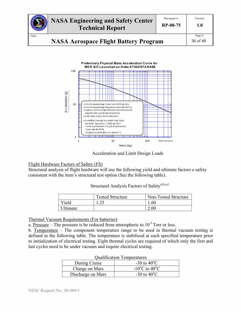
NASA Engineering and Safety Center Technical Report
Document #:
RP-08-75 Version:
1.0
Title:
NASA Aerospace Flight Battery Program Page #:
36 of 49
NESC Request No.: 06-069-I
1
10
100
1 10 100
Preliminary Physical Mass Acceleration Curve forMER S/C Launched on D elta-II 7925/STA R48B
Mass (kg)
PENG 06-Aug-00
o Use for appendage mass up to 500 kg onlyo Use for appendage frequency less than 80 H zo Apply in wors t single dir ec tion (not necessari ly al igned with coor dinate dir ec tions)o Add static 2.2g in thrus t direc tion
o In addition, des ign to a s tatic load case (no MAC ; based on ~1,000 kg S/C): - Ax ial acceleration 7.5 g (Compress ion) - Spin r ate 80 RPM - Angular acceleration 11 r ad/sec^2
Acceleration and Limit Design Loads
Flight Hardware Factors of Safety (FS) Structural analysis of flight hardware will use the following yield and ultimate factors o safety consistent with the item’s structural test option (See the following table).
Structural Analysis Factors of Safetya,b,c,d
Tested Structure Non-Tested Structure Yield 1.25 1.60 Ultimate 2.00
Thermal Vacuum Requirements (For batteries) a. Pressure – The pressure is be reduced from atmospheric to 10-5 Torr or less. b. Temperature – The component temperature range to be used in thermal vacuum testing is defined in the following table. The temperature is stabilized at each specified temperature prior to initialization of electrical testing. Eight thermal cycles are required of which only the first and last cycles need to be under vacuum and require electrical testing.
Qualification Temperatures
During Cruise -30 to 40oC Charge on Mars -10oC to 40oC
Discharge on Mars -30 to 40oC
NASA Engineering and Safety Center Technical Report
Document #:
RP-08-75 Version:
1.0
Title:
NASA Aerospace Flight Battery Program Page #:
37 of 49
NESC Request No.: 06-069-I
Thermal Cycle Requirements Each battery in the battery unit will be tested and monitored. The temperature range to be used in thermal cycle testing is –20 and +40°C. The temperature is stabilized at each specified temperature prior to initialization of electrical testing. Eight thermal cycles are performed on the Qualification battery. On the final cycle the capacity tests shown in the following table are repeated. The capacities need to meet the BOL battery capacity requirements as described in the requirements except for the required capacity at 40oC, which would be the same as 20oC.
Thermal Vacuum Test Conditions Description 20°C
Charge at 0.8 A to 32.8V(a) then taper to 0.32A. Discharge at 0.8 A to cutoff voltage of 24V or first cell to 3.0V. Recharge to 32.8V(a) then taper to 0.32A.
0°C
Discharge at 0.8 A to cutoff voltage of 24V or first cell to 3.0V Charge at 0.8 A to 32.8V(a) then taper to 0.32A
-20°C
Discharge at 0.8 A to cutoff voltage of 24V or first cell to 3.0V Charge at 0.8A to 32.8V(a) then taper to 0.32A
-30°C Discharge at 0.8 A to cutoff voltage of 24V or first cell to 3.0V
+40C Charge at 0.8A to 32.8V(a) then taper to 0.32A Discharge at 0.8 A to cutoff voltage of 24V or first cell to 3.0V Charge at 0.8A to 32.8V(a) then taper to 0.32A
20oC Discharge at 0.8 A to cutoff voltage of 24V or first cell to 3.0V Charge at 0.8 A to 32.8V(a) then taper to 0.32A .Repeat discharge at 4A and 8A. Charge at 0.8 A to 32.8V(a) then taper to 0.32A
Thermal Cycle Repeat Thermal cycle 8 times without electrical testing
8th Cycle Repeat all electrical measurements as performed for Thermal/Vac on Cycle 1
Note: Charge switches to taper at 32.8 V or when first cell reaches 4.15V Profile Test Testing will be performed to the specific mission profile. Launch Pressure Decay The battery should be designed for payload fairing venting as shown in the following figure at a pressure decay rate of 33 Torr/sec and shown by analysis.
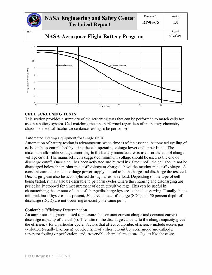
NASA Engineering and Safety Center Technical Report
Document #:
RP-08-75 Version:
1.0
Title:
NASA Aerospace Flight Battery Program Page #:
38 of 49
NESC Request No.: 06-069-I
Maximum PressureMinimum Pressure
Time (sec)
Com
part
men
t Pre
ssur
e (P
SI)
0 10 20 30 40 50 60 700
2
8
4
6
10
12
14
16
CELL SCREENING TESTS This section provides a summary of the screening tests that can be performed to match cells for use in a battery system. Cell matching must be performed regardless of the battery chemistry chosen or the qualification/acceptance testing to be performed. Automated Testing Equipment for Single Cells Automation of battery testing is advantageous when time is of the essence. Automated cycling of cells can be accomplished by using the cell operating voltage lower and upper limits. The maximum allowable voltage according to the battery manufacturer is used for the end of charge voltage cutoff. The manufacturer’s suggested minimum voltage should be used as the end of discharge cutoff. Once a cell has been activated and burned in (if required), the cell should not be discharged below the minimum cutoff voltage or charged above the maximum cutoff voltage. A constant current, constant voltage power supply is used to both charge and discharge the test cell. Discharging can also be accomplished through a resistive load. Depending on the type of cell being tested, it may also be desirable to perform cycles where the charging and discharging are periodically stopped for a measurement of open circuit voltage. This can be useful in characterizing the amount of state-of-charge/discharge hysteresis that is occurring. Usually this is minimal, but if hysteresis is present, 50 percent state-of-charge (SOC) and 50 percent depth-of-discharge (DOD) are not occurring at exactly the same point. Coulombic Efficiency Determination An amp-hour integrator is used to measure the constant current charge and constant current discharge capacity of the cell(s). The ratio of the discharge capacity to the charge capacity gives the efficiency for a particular cycle. Factors that affect coulombic efficiency include excess gas evolution (usually hydrogen), development of a short circuit between anode and cathode, separator fouling or perforation, and irreversible chemical reactions. Cycles like these are
NASA Engineering and Safety Center Technical Report
Document #:
RP-08-75 Version:
1.0
Title:
NASA Aerospace Flight Battery Program Page #:
39 of 49
NESC Request No.: 06-069-I
required to be able to determine state-of-charge and depth-of-discharge. If a large number of cycles are performed, such as in a life test, a determination of useful life can be made. Polarization Testing The electrochemical activity of a cell should be determined periodically by measuring its voltage-current relationship. These tests are performed by applying the required current (5 or 6 different current settings within the capabilities of the cell used should be chosen) in charge mode for about 20 seconds and then in discharge mode for about 20 seconds. (Note: Exceeding the rated current carrying capability of a given cell can lead to permanent damage even for short term exposures such as this. Choose test current density values carefully). In this way, the cell state-of-charge should remain approximately the same at the end of the test as it was at the beginning of the test. This test should be done at 25, 50, and 75 percent SOC. The degree of linearity of the plotted data (voltage as a function of current density) indicates whether the electrode is exhibiting kinetic or concentration polarization effects. Kinetic effects and poor mass transport properties are evidenced by non-linearities at low and high current densities. The internal resistance of the cell can be calculated by determining the slope of the discharge curves at each of the states-of-charge. Cell resistance can also be measured with an impedance bridge at 1000 Hz. This measurement generally is in good agreement with the resistance calculated from the slope of the voltage-current relationship. Open Circuit Decay Test This simple test involves stopping during charge and/or discharge cycles at specific intervals (usually based on SOC), and observing the rate of decay for a fixed time interval. Usually 25, 50, and 75 percent SOC are chosen for convenience. Cells with steeper decay rates should be eliminated from consideration. Tailoring Screening Tests Screening tests can be tailored to individual cell types. A series of combination cycles can be run which would allow the engineer to graphically observe deviations in cell behavior. For example, 1.5 Ampere hour Lithium ion cells can be cycled in the following way for screening purposes. By analyzing the plotted data, performance differences can be easily seen. Begin with a C rate charge at anything from C/1 to C/10 to a maximum of 4.2V. Then switch the cell to open circuit (or wait state) for a short period of time (usually for several minutes; the same wait time should be used for all cells of the same type). At the end of the wait state, observe and note the voltage decay, and then do the following special discharge: Discharge at C/1 for 1 minute, then without hesitation, switch to a C/10 discharge down to 2.4 volts. All graphical data should be plotted using the same scale values. The resulting voltage vs. time curve should be an upward sloping charge curve with the expected peaks, followed by a self discharge dip or notch, attached to a steep downward curve that abruptly turns upward caused by the reduction in the discharge rate. The difference between the C/1 discharge and the upturn resulting from the abrupt decrease in discharge rate allows the internal resistance of the cell to be determined. Finally, after the initial rise, the discharge curve decreases back down into a more
NASA Engineering and Safety Center Technical Report
Document #:
RP-08-75 Version:
1.0
Title:
NASA Aerospace Flight Battery Program Page #:
40 of 49
NESC Request No.: 06-069-I
typical slope. Continue to test the cells in question for about 50 cycles. After about 50 of these special cycles, analyze the data to pick out cells that can be assembled into a string of cells. THERMAL TESTS Cells and batteries should be tested in an environment that is as close to the intended application as possible. Thermal environment in particular is a factor that significantly affects how a battery will perform. Most cells function more efficiently at warmer temperatures rather than cold. Depending on the cell type, batteries may require active thermal management (circulating coolant), passive thermal management (insulation or heat sink), or a special location (waste heat conducted from nearby electronics). Frequently, more cells are required in a battery that will be operating in a low temperature environment. Consult the manufacturer of the cells to determine known behavior at low and high temperatures. If the manufacturer has not performed testing at the temperature of interest, thermal screening tests will be needed for the temperature range in question. COTS MULTI-CELL BATTERY TEST PROGRAM NASA Johnson Space Center (JSC) has a stringent test program for testing new Commercial-Off-the-Shelf (COTS) batteries (string of COTS cells). There are three major parts of the test program: (1) engineering/certification test; (2) qualification test of batteries; and (3) flight acceptance test. The engineering certification test requires testing individual cells and the battery for performance and abuse. The qualification test includes environmental testing. JSC can perform this test program for projects if requested. In addition, JSC may already have gathered considerable test data for the type of battery/cells being considered by the project. A request for this type of historical data may allow a project to dispense with some of the testing outlined below. Engineering/Certification Tests Engineering/certifications tests are performed primarily to eliminate those batteries with workmanship problems, and to gain familiarity with the behavior of the battery as an assembly of a string of individual cells. Battery Level Performance Testing The following are key battery level performance tests:
• Open Circuit Voltage (OCV) measurement of “as obtained” batteries • Constant Capacity Voltage (CCV) - load equivalent to 1.5 C current for 100 ms pulse • Functional performance of battery by performing in-situ testing or by mission
simulation; some cells perform differently in a battery system than as individual cells • Thermal environment – performance of batteries at 20°F above and below flight
operational environment • Vacuum leak check – to check for leakage and tolerance for up to six hours of
exposure to vacuum environment

NASA Engineering and Safety Center Technical Report
Document #:
RP-08-75 Version:
1.0
Title:
NASA Aerospace Flight Battery Program Page #:
41 of 49
NESC Request No.: 06-069-I
• Leak check on 100% of flight batteries - qualification/certification test is performed on engineering and qualification hardware.
• Vibration – batteries and cells are vibrated to determine vibration tolerance to
launch and descent. Test vibration is very much dependant on launch and landing environments, number of missions, and cell chemistry.
• Used as a screening method for workmanship standards.
• Used as a screening method for internal shorts in some lithium primary and all Li-
Ion cells/batteries.
• Typical vibration spectrum for qualification is at least five times higher than that for flight acceptance and at longer than flight durations. Acceptance vibration is performed on 100% of flight batteries to screen for internal shorts and/or workmanship defects.
Abuse Tests The following are key battery level abuse tests for battery screening and matching:
• Overcharge o Typical failures: charger failure; protective circuit board failure o Cell level: 3C rate fast charge, over-voltage (to 5.0 V for Li-ion); overcharge to
12.0 V for 50 minutes (UL test) o Battery level: verify protective feature for overcharge/over-voltage
• Overdischarge test o Typical failures: low-voltage cutoff (in equipment) failure; protective circuit
board failure o Cell level: fast discharge at 3 C rate; discharge into reversal o Battery level: Characterize low voltage cutoff switch setting; verify logic in
circuitry to determine if individual cell voltage or total battery voltage opens the safety MOSFET switch
• External short circuit test o Typical failures: inadvertent shorting across terminals; hard-blow/thermal fuse
failure; protective “smart” circuit board failure; multi-switch failure o Cell and battery level: external hard short is deliberately imposed on the battery
under carefully controlled conditions • Internal short circuit test (crush)
o Presence of impurities (metal burrs, particles, dust) that can be dislodged due to vibration (manufacturing defect) are common causes of short circuits
o Simulated internal short using a crush method. • High temperature and heat-to-vent
NASA Engineering and Safety Center Technical Report
Document #:
RP-08-75 Version:
1.0
Title:
NASA Aerospace Flight Battery Program Page #:
42 of 49
NESC Request No.: 06-069-I
o Temperature tolerance on cells and determination of thermal runaway temperatures
o Requires cells be well instrumented with thermal measuring devices • Drop/Shock test
o Simulates problems encountered during ground handling and transportation – inadvertent drops
• Vent and burst pressure test o Vent/burst pressure ratio ≥ 2.5
• Destructive Physical Analysis (DPA) with electrolyte analysis o For toxicology assessment and report (independent materials usage and
toxicological memos required) VIBRATION TESTING AND TOLERANCE TO INTERNAL SHORTS Since the absence of internal shorts cannot be proven with confidence, a screening method has been developed at NASA-JSC-EP5 for the removal of cells/batteries with this type of defects. The cells/batteries are tested to prove tolerance (no venting, fire or explosion) to internal shorts using simulated methods. If such tolerance is not observed, batteries and cells are screened with a level of vibration that is higher than workmanship levels (see above paragraphs on testing batteries that are intolerant to internal shorts). The vibration spectrum may also be determined by the hardware provider in conjunction with the Power Systems Office battery evaluator. Qualification Vibration Testing (QVT) for Batteries Tolerant to Internal Shorts The purpose of the qualification vibration test for those batteries that are tolerant to internal shorts is to demonstrate the ability of the component to withstand the stresses and accumulated fatigue damage resulting from the maximum random vibration environment. The test duration in each of the three orthogonal axes is equivalent to either the total acceptance vibration test time the battery will experience or five minutes, whichever is greater. The test levels and spectrum are shown in the following figure and table. Test condition tolerances are applied to the nominal values defined in the following figure and table. A maximum allowable tolerance of +/-1.5 dB is applied to the Power Spectral Density values. Any aspect of the test not specifically defined in this document will conducted in accordance with the applicable requirement.
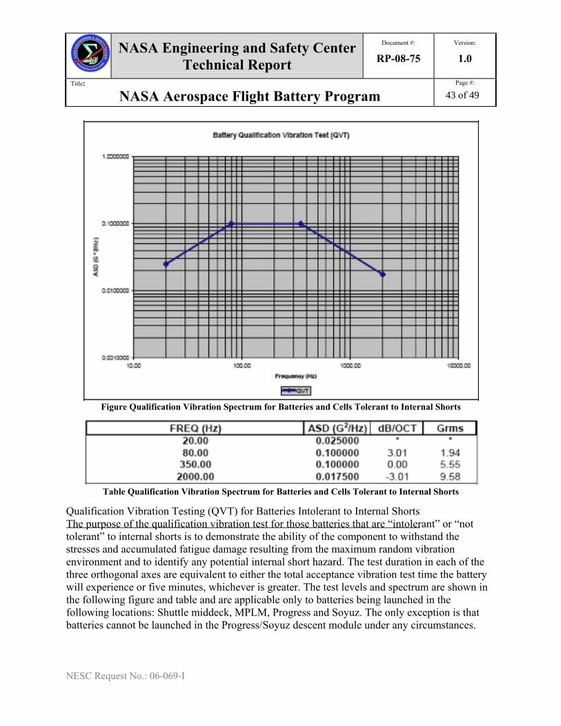
NASA Engineering and Safety Center Technical Report
Document #:
RP-08-75Version:
1.0
Title:
NASA Aerospace Flight Battery Program Page #:
43 of 49
NESC Request No.: 06-069-I
Figure Qualification Vibration Spectrum for Batteries and Cells Tolerant to Internal Shorts
Table Qualification Vibration Spectrum for Batteries and Cells Tolerant to Internal Shorts
Qualification Vibration Testing (QVT) for Batteries Intolerant to Internal Shorts The purpose of the qualification vibration test for those batteries that are “intolerant” or “not tolerant” to internal shorts is to demonstrate the ability of the component to withstand the stresses and accumulated fatigue damage resulting from the maximum random vibration environment and to identify any potential internal short hazard. The test duration in each of the three orthogonal axes are equivalent to either the total acceptance vibration test time the battery will experience or five minutes, whichever is greater. The test levels and spectrum are shown in the following figure and table and are applicable only to batteries being launched in the following locations: Shuttle middeck, MPLM, Progress and Soyuz. The only exception is that batteries cannot be launched in the Progress/Soyuz descent module under any circumstances.
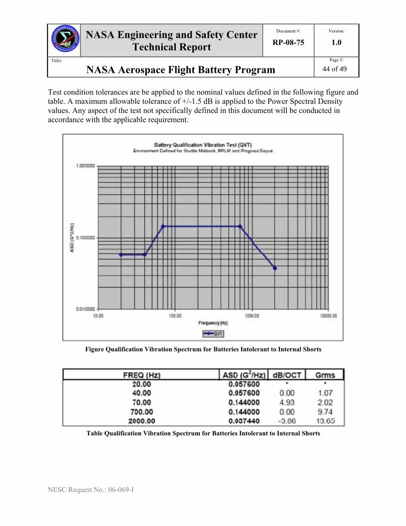
NASA Engineering and Safety Center Technical Report
Document #:
RP-08-75Version:
1.0
Title:
NASA Aerospace Flight Battery Program Page #:
44 of 49
NESC Request No.: 06-069-I
Test condition tolerances are be applied to the nominal values defined in the following figure and table. A maximum allowable tolerance of +/-1.5 dB is applied to the Power Spectral Density values. Any aspect of the test not specifically defined in this document will be conducted in accordance with the applicable requirement.
Figure Qualification Vibration Spectrum for Batteries Intolerant to Internal Shorts
Table Qualification Vibration Spectrum for Batteries Intolerant to Internal Shorts
NASA Engineering and Safety Center Technical Report
Document #:
RP-08-75 Version:
1.0
Title:
NASA Aerospace Flight Battery Program Page #:
45 of 49
NESC Request No.: 06-069-I
9. References 1. Crewed Space Vehicle Battery Safety Requirements, Judith Jeevarajan, Eric Darcy, & William Hoffman, NASA Johnson Space Center, Engineering Directorate, Energy Systems Division, Revision B, JSC-20793 Rev. B, April, 2006 2. Battery Safety and Design Manual for Payloads, Jerri S. Ling, NASA Glenn Research Center, Risk Management Office Document, GLM-QE-8715.1 - Rev. Basic, January 16, 2007 3. Acquisition Standard for Lithium-Ion Based Launch Vehicle Batteries, Margot L. Wasz, Aerospace Corporation, Aerospace Report No. TOR-2007(8583)-2, 15 January 2008 4. Lithium-Ion Battery Standards for Spacecraft Applications, V. J. Ang, Aerospace Corporation, Aerospace Report No. TOR-2007(8583)-1, 30 June 2007 5. Battery Processing, Judith Jeevarajan, Eric Darcy, & Patricia Petete, NASA Johnson Space Center, Engineering Directorate, EA-CWI-033, January 2005 6. List of Acceptance and Reliability Tests on Li-ion Batteries, R. V. Bugga, Jet Propulsion Laboratory, internal memo, 2007 7. Memo on Joint 45 SW/SE and 30 SW/SE Interim Policy Regarding EWR 127-1 Requirements for System Safety for Flight and Aerospace Ground Equipment Lithium-Ion Batteries, Robert D. Gibson, Lt. Col. & David H. Nuckles, Jr., Col., Department of the Air Force, 30th Space Wing (AFSPC), 04 May 2005 8. Flight Termination Systems Commonality Standard, Range Safety Group, Range Commanders Council, U.S. Army White Sands Missile Range, Document 319-07, August 2007 9. Lithium Ion Battery Acceptance/Safety Test Report Procurement Specification, MISSE5/PCSat2 Project, J. Christopher Garner, Naval Research Laboratory, Naval Center for Space Technology, NCST-TR-MI001, 29 April 2004 10. Space Engineering, Electrical and Electronic Standard, European Cooperation for Space Standardization, ECSS-E-20A, 4 October 1999 11. Qualification and Acceptance Environmental Test Requirements, NASA International Space Station Program, SSP 41172, Revision U, 28 March 2003
NASA Engineering and Safety Center Technical Report
Document #:
RP-08-75 Version:
1.0
Title:
NASA Aerospace Flight Battery Program Page #:
46 of 49
NESC Request No.: 06-069-I
12. Specification for Lot Testing and Flight Screening of Canon BP 927 and BP 930 Lithium-Ion Batteries, NASA Johnson Space Center, Engineering Directorate, EP-WI-015, Rev. B 13. Space Engineering, Space Product Assurance, European Cooperation for Space Standardization, ECSS-Q-40B, 17 May 2002 14. Qualification and Acceptance Environmental Test Requirements, International Space Station Program, Everett Auzenne, NASA Johnson Space Center, SSP 41172, Rev. U, 28 March 2003 15. NASA Procedural Requirements 8715.5 “Range Safety Program”, NASA Office of Safety and Mission Assurance, July 8, 2005 16. Eastern and Western Range Safety, Range Safety Office, Patrick AFB, EWR 127-1, Rev. 1, 31 December 1999 17. Range Safety User Requirements Manual, Volume 4-Launch Vehicles Payloads and Ground Support Systems Requirements, Air Force Space Command, AFSPC91-710, July 1, 2004
Appendix A: Definitions Battery A Battery is an assembly of battery cells or modules electrically connected (usually in series) to provide the desired voltage and current capability. Generally, the cells are physically integrated into either a single assembly (or battery) or into several separate assemblies (or modules). A battery may also include one or more attachments, such as electrical bypass devices, charge control electronics, heaters, temperature sensors, thermal switches, and thermal control elements. Calendar Life The calendar life of a cell or battery is the maximum allowed period of use of the cell or battery as defined from the date of manufacture of the oldest cell in the battery. Capacity Battery Capacity is measured in units of Ampere-hours (for Ah capacity) or Watt-hours (for Wh capacity). Battery capacity is equal to the integral of the discharge current, where Id is a positive value. The limits of integration are from start of discharge to either the minimum power subsystem battery voltage limit, or when the first cell reaches the lower cell voltage limit, or when a defined time duration is reached. This is a point-in-time capacity value that is measured at a defined charge voltage-current profile, discharge load profile, and temperature profile. Battery capacity (Ah) = ∫Iddt Battery capacity (WH) = ∫IdVddt
NASA Engineering and Safety Center Technical Report
Document #:
RP-08-75 Version:
1.0
Title:
NASA Aerospace Flight Battery Program Page #:
47 of 49
NESC Request No.: 06-069-I
Cell (or Battery Cell) A cell is a single-unit device within one cell case that transforms chemical energy into electrical energy at characteristic voltages when discharged. Battery cells can be connected (usually in series) to form a battery. Battery cells can be connected in series or parallel to form a module; in such cases, the modules are connected (usually in series) to form a battery. Cell Activation The addition of electrolyte to a battery cell constitutes cell activation and starts the clock on cell, module, and battery service life. It is used to define the start of battery shelf life. Li-ion cells are activated at the manufacturing facility during cell production. Following activation, Li-Ion cells typically undergo several charge/discharge cycles to condition the surface of the electrodes and stabilize capacity. Cell Design A cell design is built to one set of manufacturing control documents that define material composition, dimensions, quantity, process, and process controls for each component in the cell. A change in cell design is considered a different cell design that requires a separate qualification. A change in cell design includes, but is not limited to, the following: - Positive electrode composition, raw material (including binder), loading density, foil, dimension, or process change - Negative electrode composition, raw material (including binder), loading density, foil, dimension, or process change - Electrolyte composition - Separator composition or dimension - Cell stack dimension or composition - Cell case size - Change in cell or raw material manufacturing location - Terminal seal Cell Lot A cell lot is a continuous, uninterrupted production run of cells, which consists of a anode, cathode, electrolyte material, and separator, from the same raw material sublots with no change in processes or drawings. Li-Ion cells produced in a single lot should be procured, stored, delivered, and tested together to maintain single lot definition. Charge/Discharge Current C/n (or C-rate) The constant charge or discharge current for a battery is defined as C/n, or C-rate. C is the cell-level rated (or nameplate) capacity in Ampere-hours (per vendor’s criteria), and n is any value for elapsed time measure in hours. For example, a discharge current of C/2 for a 20 A-h rated cell is a discharge current of 10 A.
NASA Engineering and Safety Center Technical Report
Document #:
RP-08-75 Version:
1.0
Title:
NASA Aerospace Flight Battery Program Page #:
48 of 49
NESC Request No.: 06-069-I
Cold Storage Cold storage, for batteries that are not in use, is long-term storage where the temperature and humidity environments are controlled, and temperature is below ambient temperature. Cycle Life The number of discharge/charge cycles performed by the battery. Depth of Discharge (DOD) The ratio of the number of Ampere-hours removed from a battery for a defined charge voltage-current profile, discharge load profile, and temperature profile to the battery rated (or nameplate) capacity E(Ah), times 100. For a Li-Ion battery, the DOD must be specified at a state-of-charge operation or a voltage that relates to state-of-charge operation. Battery Depth-of-Dishcharge (%) = [E(Ah) removed/ E(Ah) rated]*100 Note: For batteries that are subcharged, i.e., not recharged to full energy, DOD is the percentage of energy expended in a discharge from the subcharged point. For example, a battery that is subcharged to 70% SOC and then cycled down to 40% SOC is considered to have cycled over 30% of its energy, and the DOD is 30%. Energy Launch, transfer orbit, and on-orbit battery energy and energy reserve requirements are flowed down from the Electrical Power Subsystem specification for the entire mission life. Battery energy is equal to the integral of the product of discharge current and voltage, where Id, a positive value, is the discharge current, and Vd, a positive value, is the discharge voltage. The limits of integration are from start of discharge to either the minimum power subsystem battery voltage limit, or when the first cell reaches the lower cell voltage limit, or when a defined time duration is reached. This is a point-in-time energy value that is measured at a defined charge voltage-current profile, discharge load profile, and temperature profile. Battery discharge can be accomplished with constant current discharge; however, constant power discharge is the preferred method if it more closely simulates spacecraft power. This is also sometimes called Watt-hour capacity. Battery Energy (Wh) =∫ IdVddt Energy Reserve Total amount of usable energy in Watt-hours remaining in a battery, which has been discharged to the maximum allowed DOD under normal operating conditions to either the minimum power subsystem battery voltage limit, or when the first cell reaches the lower cell voltage limit.
NASA Engineering and Safety Center Technical Report
Document #:
RP-08-75 Version:
1.0
Title:
NASA Aerospace Flight Battery Program Page #:
49 of 49
NESC Request No.: 06-069-I
Note: Energy reserve provides enough energy to ensure positive energy balance during the maximum sun-outage time when a loss of attitude control occurs coincident with the end of the longest eclipse. Energy reserve may also be used for other rare, deep discharges such as relocation with electric propulsion, or those that may occur in transfer orbit. Maximum Expected Operating Pressure The maximum pressure that pressurized hardware is expected to experience during its service life, in association with its applicable operating environments. Module (or Battery Module) A battery module is an assembly of series- or parallel-connected battery cells that are connected (usually in series) to form a battery. Procurement Authority The agency responsible for the procurement of the spacecraft. Rated or Nameplate Capacity The rated or nameplate battery capacity is measured in units of Ampere-hours or Watt-hours. The rated battery capacity is provided by the battery or cell vendor and is typically less than the actual capacity. Manufacturers usually provide excess capacity over the rated value to compensate for variability within the manufacturing lot and capacity losses expected over the life of the battery. Service Life The service life of a battery, battery module, or battery cell starts at cell activation and continues through all subsequent fabrication, acceptance testing, handling, storage, transportation, testing preceding launch, launch, and mission operation. Shelf Life Limit Shelf life limit for a battery, module, or cell is the maximum allowed time from cell activation to launch. This includes any time in cold storage. State of Charge The ratio of the number of Ah or Wh present in a battery for a defined charge voltage-current profile, discharge load profile, and temperature profile to the rated energy E(Ah or Wh) of the battery, times 100. Battery State-of-Charge (%) = [E(Ah or Wh) present/E(Ah or Wh) rated]*100
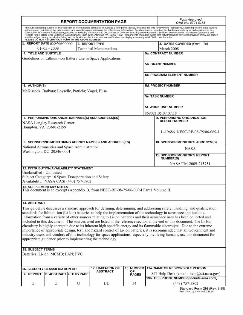
REPORT DOCUMENTATION PAGE Form ApprovedOMB No. 0704-0188
2. REPORT TYPE Technical Memorandum
4. TITLE AND SUBTITLEGuidelines on Lithium-ion Battery Use in Space Applications
5a. CONTRACT NUMBER
6. AUTHOR(S)
McKissock, Barbara; Loyselle, Patricia; Vogel, Elisa
7. PERFORMING ORGANIZATION NAME(S) AND ADDRESS(ES)NASA Langley Research CenterHampton, VA 23681-2199
9. SPONSORING/MONITORING AGENCY NAME(S) AND ADDRESS(ES)National Aeronautics and Space AdministrationWashington, DC 20546-0001
8. PERFORMING ORGANIZATION REPORT NUMBER
L-19686 NESC-RP-08-75/06-069-I
10. SPONSOR/MONITOR'S ACRONYM(S)
NASA
13. SUPPLEMENTARY NOTESThis document is an excerpt (Appendix B) from NESC-RP-08-75/06-069-I Part 1 Volume II.
12. DISTRIBUTION/AVAILABILITY STATEMENTUnclassified - UnlimitedSubject Category: 16 Space Trsnsportation and SafetyAvailability: NASA CASI (443) 757-5802
19a. NAME OF RESPONSIBLE PERSON
STI Help Desk (email: [email protected])
14. ABSTRACT
This guideline discusses a standard approach for defining, determining, and addressing safety, handling, and qualification standards for lithium-ion (Li-Ion) batteries to help the implementation of the technology in aerospace applications. Information from a variety of other sources relating to Li-ion batteries and their aerospace uses has been collected and included in this document. The sources used are listed in the reference section at the end of this document. The Li-Ion chemistry is highly energetic due to its inherent high specific energy and its flammable electrolyte. Due to the extreme importance of appropriate design, test, and hazard control of Li-ion batteries, it is recommended that all Government and industry users and vendors of this technology for space applications, especially involving humans, use this document for appropriate guidance prior to implementing the technology.
15. SUBJECT TERMSBatteries; Li-ion; MCMB; PAN; PVC
18. NUMBER OF PAGES
5419b. TELEPHONE NUMBER (Include area code)
(443) 757-5802
a. REPORT
U
c. THIS PAGE
U
b. ABSTRACT
U
17. LIMITATION OF ABSTRACT
UU
Prescribed by ANSI Std. Z39.18Standard Form 298 (Rev. 8-98)
3. DATES COVERED (From - To)March 2008
5b. GRANT NUMBER
5c. PROGRAM ELEMENT NUMBER
5d. PROJECT NUMBER
5e. TASK NUMBER
5f. WORK UNIT NUMBER
869021.05.07.07.18
11. SPONSOR/MONITOR'S REPORT NUMBER(S)
NASA/TM-2009-215751
16. SECURITY CLASSIFICATION OF:
The public reporting burden for this collection of information is estimated to average 1 hour per response, including the time for reviewing instructions, searching existing data sources, gathering and maintaining the data needed, and completing and reviewing the collection of information. Send comments regarding this burden estimate or any other aspect of this collection of information, including suggestions for reducing this burden, to Department of Defense, Washington Headquarters Services, Directorate for Information Operations and Reports (0704-0188), 1215 Jefferson Davis Highway, Suite 1204, Arlington, VA 22202-4302. Respondents should be aware that notwithstanding any other provision of law, no person shall be subject to any penalty for failing to comply with a collection of information if it does not display a currently valid OMB control number.PLEASE DO NOT RETURN YOUR FORM TO THE ABOVE ADDRESS.
1. REPORT DATE (DD-MM-YYYY)05 - 200901-